TAP1500 1.5 GHz, 10X Active Probe Instruction Manual
65
TAP1500 1.5 GHz, 10X Active Probe Instruction Manual www.tektronix.com 071-1809-00
Transcript of TAP1500 1.5 GHz, 10X Active Probe Instruction Manual

TAP15001.5 GHz, 10X Active ProbeInstruction Manual
www.tektronix.com071-1809-00

Copyright © Tektronix. All rights reserved. Licensed software products are owned by Tektronix or its subsidiaries or suppliers, and are protected bynational copyright laws and international treaty provisions.
Tektronix products are covered by U.S. and foreign patents, issued and pending. Information in this publication supersedes that in all previouslypublished material. Specifications and price change privileges reserved.
TEKTRONIX and TEK are registered trademarks of Tektronix, Inc.
Contacting TektronixTektronix, Inc.14200 SW Karl Braun DriveP.O. Box 500Beaverton, OR 97077USA
For product information, sales, service, and technical support:In North America, call 1-800-833-9200.Worldwide, visit www.tektronix.com to find contacts in your area.

Warranty 2Tektronix warrants that this product will be free from defects in materials and workmanship for a period of one (1) year from the date of shipment. Ifany such product proves defective during this warranty period, Tektronix, at its option, either will repair the defective product without charge for partsand labor, or will provide a replacement in exchange for the defective product. Parts, modules and replacement products used by Tektronix forwarranty work may be new or reconditioned to like new performance. All replaced parts, modules and products become the property of Tektronix.
In order to obtain service under this warranty, Customer must notify Tektronix of the defect before the expiration of the warranty period and makesuitable arrangements for the performance of service. Customer shall be responsible for packaging and shipping the defective product to the servicecenter designated by Tektronix, with shipping charges prepaid. Tektronix shall pay for the return of the product to Customer if the shipment is to alocation within the country in which the Tektronix service center is located. Customer shall be responsible for paying all shipping charges, duties,taxes, and any other charges for products returned to any other locations.
This warranty shall not apply to any defect, failure or damage caused by improper use or improper or inadequate maintenance and care. Tektronixshall not be obligated to furnish service under this warranty a) to repair damage resulting from attempts by personnel other than Tektronixrepresentatives to install, repair or service the product; b) to repair damage resulting from improper use or connection to incompatible equipment; c) torepair any damage or malfunction caused by the use of non-Tektronix supplies; or d) to service a product that has been modified or integrated withother products when the effect of such modification or integration increases the time or difficulty of servicing the product.
THIS WARRANTY IS GIVEN BY TEKTRONIX WITH RESPECT TO THE PRODUCT IN LIEU OF ANY OTHER WARRANTIES, EXPRESS ORIMPLIED. TEKTRONIX AND ITS VENDORS DISCLAIM ANY IMPLIED WARRANTIES OF MERCHANTABILITY OR FITNESS FOR A PARTICULARPURPOSE. TEKTRONIX’ RESPONSIBILITY TO REPAIR OR REPLACE DEFECTIVE PRODUCTS IS THE SOLE AND EXCLUSIVE REMEDYPROVIDED TO THE CUSTOMER FOR BREACH OF THIS WARRANTY. TEKTRONIX AND ITS VENDORS WILL NOT BE LIABLE FOR ANYINDIRECT, SPECIAL, INCIDENTAL, OR CONSEQUENTIAL DAMAGES IRRESPECTIVE OF WHETHER TEKTRONIX OR THE VENDOR HASADVANCE NOTICE OF THE POSSIBILITY OF SUCH DAMAGES.


Table of Contents
Table of ContentsGeneral Safety Summary . . . . . . . . . . . . . . . . . . . . . . . . . . . . . . . . . . . . . . . . . . . . . . . . . . . . . . . . . . . . . . . . . . . . . . . . . . . . . . . . . . . . . . . . . . . . . . . . . . . . . . . . . . . . . . . . . . iii
Service Safety Summary . . . . . . . . . . . . . . . . . . . . . . . . . . . . . . . . . . . . . . . . . . . . . . . . . . . . . . . . . . . . . . . . . . . . . . . . . . . . . . . . . . . . . . . . . . . . . . . . . . . . . . . . . . . . . . . . . . . . v
Environmental Considerations . . . . . . . . . . . . . . . . . . . . . . . . . . . . . . . . . . . . . . . . . . . . . . . . . . . . . . . . . . . . . . . . . . . . . . . . . . . . . . . . . . . . . . . . . . . . . . . . . . . . . . . . . . . . . vi
Preface. . . . . . . . . . . . . . . . . . . . . . . . . . . . . . . . . . . . . . . . . . . . . . . . . . . . . . . . . . . . . . . . . . . . . . . . . . . . . . . . . . . . . . . . . . . . . . . . . . . . . . . . . . . . . . . . . . . . . . . . . . . . . . . . . . . . . viiiDocumentation . . . . . . . . . . . . . . . . . . . . . . . . . . . . . . . . . . . . . . . . . . . . . . . . . . . . . . . . . . . . . . . . . . . . . . . . . . . . . . . . . . . . . . . . . . . . . . . . . . . . . . . . . . . . . . . . . . . . . . . viiiConventions Used in This Manual. . . . . . . . . . . . . . . . . . . . . . . . . . . . . . . . . . . . . . . . . . . . . . . . . . . . . . . . . . . . . . . . . . . . . . . . . . . . . . . . . . . . . . . . . . . . . . . . . . . viiiReturning the Probe for Servicing . . . . . . . . . . . . . . . . . . . . . . . . . . . . . . . . . . . . . . . . . . . . . . . . . . . . . . . . . . . . . . . . . . . . . . . . . . . . . . . . . . . . . . . . . . . . . . . . . . . . ix
Key Features . . . . . . . . . . . . . . . . . . . . . . . . . . . . . . . . . . . . . . . . . . . . . . . . . . . . . . . . . . . . . . . . . . . . . . . . . . . . . . . . . . . . . . . . . . . . . . . . . . . . . . . . . . . . . . . . . . . . . . . . . . . . . . . 1
Installation . . . . . . . . . . . . . . . . . . . . . . . . . . . . . . . . . . . . . . . . . . . . . . . . . . . . . . . . . . . . . . . . . . . . . . . . . . . . . . . . . . . . . . . . . . . . . . . . . . . . . . . . . . . . . . . . . . . . . . . . . . . . . . . . . . 2Connecting to the Host Instrument . . . . . . . . . . . . . . . . . . . . . . . . . . . . . . . . . . . . . . . . . . . . . . . . . . . . . . . . . . . . . . . . . . . . . . . . . . . . . . . . . . . . . . . . . . . . . . . . . . . 2Probe Controls and Indicators . . . . . . . . . . . . . . . . . . . . . . . . . . . . . . . . . . . . . . . . . . . . . . . . . . . . . . . . . . . . . . . . . . . . . . . . . . . . . . . . . . . . . . . . . . . . . . . . . . . . . . . . 3
Functional Check . . . . . . . . . . . . . . . . . . . . . . . . . . . . . . . . . . . . . . . . . . . . . . . . . . . . . . . . . . . . . . . . . . . . . . . . . . . . . . . . . . . . . . . . . . . . . . . . . . . . . . . . . . . . . . . . . . . . . . . . . . . 6Required Equipment . . . . . . . . . . . . . . . . . . . . . . . . . . . . . . . . . . . . . . . . . . . . . . . . . . . . . . . . . . . . . . . . . . . . . . . . . . . . . . . . . . . . . . . . . . . . . . . . . . . . . . . . . . . . . . . . . . 6
Basic Operation. . . . . . . . . . . . . . . . . . . . . . . . . . . . . . . . . . . . . . . . . . . . . . . . . . . . . . . . . . . . . . . . . . . . . . . . . . . . . . . . . . . . . . . . . . . . . . . . . . . . . . . . . . . . . . . . . . . . . . . . . . . . . 9Probe Head Assembly . . . . . . . . . . . . . . . . . . . . . . . . . . . . . . . . . . . . . . . . . . . . . . . . . . . . . . . . . . . . . . . . . . . . . . . . . . . . . . . . . . . . . . . . . . . . . . . . . . . . . . . . . . . . . . . . 9Probe Input. . . . . . . . . . . . . . . . . . . . . . . . . . . . . . . . . . . . . . . . . . . . . . . . . . . . . . . . . . . . . . . . . . . . . . . . . . . . . . . . . . . . . . . . . . . . . . . . . . . . . . . . . . . . . . . . . . . . . . . . . . . 10Probe Offset. . . . . . . . . . . . . . . . . . . . . . . . . . . . . . . . . . . . . . . . . . . . . . . . . . . . . . . . . . . . . . . . . . . . . . . . . . . . . . . . . . . . . . . . . . . . . . . . . . . . . . . . . . . . . . . . . . . . . . . . . . 11
Accessories and Options . . . . . . . . . . . . . . . . . . . . . . . . . . . . . . . . . . . . . . . . . . . . . . . . . . . . . . . . . . . . . . . . . . . . . . . . . . . . . . . . . . . . . . . . . . . . . . . . . . . . . . . . . . . . . . . . . . 13Using Standard Accessories . . . . . . . . . . . . . . . . . . . . . . . . . . . . . . . . . . . . . . . . . . . . . . . . . . . . . . . . . . . . . . . . . . . . . . . . . . . . . . . . . . . . . . . . . . . . . . . . . . . . . . . . 13
TAP1500 1.5 GHz, 10X Active Probe Instruction Manual i

Table of Contents
Optional Accessories . . . . . . . . . . . . . . . . . . . . . . . . . . . . . . . . . . . . . . . . . . . . . . . . . . . . . . . . . . . . . . . . . . . . . . . . . . . . . . . . . . . . . . . . . . . . . . . . . . . . . . . . . . . . . . . . 22Options . . . . . . . . . . . . . . . . . . . . . . . . . . . . . . . . . . . . . . . . . . . . . . . . . . . . . . . . . . . . . . . . . . . . . . . . . . . . . . . . . . . . . . . . . . . . . . . . . . . . . . . . . . . . . . . . . . . . . . . . . . . . . . . 24
Probing Principles . . . . . . . . . . . . . . . . . . . . . . . . . . . . . . . . . . . . . . . . . . . . . . . . . . . . . . . . . . . . . . . . . . . . . . . . . . . . . . . . . . . . . . . . . . . . . . . . . . . . . . . . . . . . . . . . . . . . . . . . . 25Ground Lead Length . . . . . . . . . . . . . . . . . . . . . . . . . . . . . . . . . . . . . . . . . . . . . . . . . . . . . . . . . . . . . . . . . . . . . . . . . . . . . . . . . . . . . . . . . . . . . . . . . . . . . . . . . . . . . . . . . 25Ground Lead Inductance . . . . . . . . . . . . . . . . . . . . . . . . . . . . . . . . . . . . . . . . . . . . . . . . . . . . . . . . . . . . . . . . . . . . . . . . . . . . . . . . . . . . . . . . . . . . . . . . . . . . . . . . . . . . 26Low-inductance Grounding . . . . . . . . . . . . . . . . . . . . . . . . . . . . . . . . . . . . . . . . . . . . . . . . . . . . . . . . . . . . . . . . . . . . . . . . . . . . . . . . . . . . . . . . . . . . . . . . . . . . . . . . . . 27SureFoot™ Grounding. . . . . . . . . . . . . . . . . . . . . . . . . . . . . . . . . . . . . . . . . . . . . . . . . . . . . . . . . . . . . . . . . . . . . . . . . . . . . . . . . . . . . . . . . . . . . . . . . . . . . . . . . . . . . . . 28Probe Tip Test Points . . . . . . . . . . . . . . . . . . . . . . . . . . . . . . . . . . . . . . . . . . . . . . . . . . . . . . . . . . . . . . . . . . . . . . . . . . . . . . . . . . . . . . . . . . . . . . . . . . . . . . . . . . . . . . . . 29Probe Tip Stabilization . . . . . . . . . . . . . . . . . . . . . . . . . . . . . . . . . . . . . . . . . . . . . . . . . . . . . . . . . . . . . . . . . . . . . . . . . . . . . . . . . . . . . . . . . . . . . . . . . . . . . . . . . . . . . . . 30
Specifications . . . . . . . . . . . . . . . . . . . . . . . . . . . . . . . . . . . . . . . . . . . . . . . . . . . . . . . . . . . . . . . . . . . . . . . . . . . . . . . . . . . . . . . . . . . . . . . . . . . . . . . . . . . . . . . . . . . . . . . . . . . . . . 31Warranted Characteristics . . . . . . . . . . . . . . . . . . . . . . . . . . . . . . . . . . . . . . . . . . . . . . . . . . . . . . . . . . . . . . . . . . . . . . . . . . . . . . . . . . . . . . . . . . . . . . . . . . . . . . . . . . . 32Typical Characteristics . . . . . . . . . . . . . . . . . . . . . . . . . . . . . . . . . . . . . . . . . . . . . . . . . . . . . . . . . . . . . . . . . . . . . . . . . . . . . . . . . . . . . . . . . . . . . . . . . . . . . . . . . . . . . . . 33Nominal Characteristics . . . . . . . . . . . . . . . . . . . . . . . . . . . . . . . . . . . . . . . . . . . . . . . . . . . . . . . . . . . . . . . . . . . . . . . . . . . . . . . . . . . . . . . . . . . . . . . . . . . . . . . . . . . . . 40
Performance Verification . . . . . . . . . . . . . . . . . . . . . . . . . . . . . . . . . . . . . . . . . . . . . . . . . . . . . . . . . . . . . . . . . . . . . . . . . . . . . . . . . . . . . . . . . . . . . . . . . . . . . . . . . . . . . . . . . . 41Equipment Required . . . . . . . . . . . . . . . . . . . . . . . . . . . . . . . . . . . . . . . . . . . . . . . . . . . . . . . . . . . . . . . . . . . . . . . . . . . . . . . . . . . . . . . . . . . . . . . . . . . . . . . . . . . . . . . . . 41Equipment Setup. . . . . . . . . . . . . . . . . . . . . . . . . . . . . . . . . . . . . . . . . . . . . . . . . . . . . . . . . . . . . . . . . . . . . . . . . . . . . . . . . . . . . . . . . . . . . . . . . . . . . . . . . . . . . . . . . . . . . 43DC Gain Accuracy . . . . . . . . . . . . . . . . . . . . . . . . . . . . . . . . . . . . . . . . . . . . . . . . . . . . . . . . . . . . . . . . . . . . . . . . . . . . . . . . . . . . . . . . . . . . . . . . . . . . . . . . . . . . . . . . . . . 44Test Record . . . . . . . . . . . . . . . . . . . . . . . . . . . . . . . . . . . . . . . . . . . . . . . . . . . . . . . . . . . . . . . . . . . . . . . . . . . . . . . . . . . . . . . . . . . . . . . . . . . . . . . . . . . . . . . . . . . . . . . . . . 47
Maintenance . . . . . . . . . . . . . . . . . . . . . . . . . . . . . . . . . . . . . . . . . . . . . . . . . . . . . . . . . . . . . . . . . . . . . . . . . . . . . . . . . . . . . . . . . . . . . . . . . . . . . . . . . . . . . . . . . . . . . . . . . . . . . . . 48Error Condition . . . . . . . . . . . . . . . . . . . . . . . . . . . . . . . . . . . . . . . . . . . . . . . . . . . . . . . . . . . . . . . . . . . . . . . . . . . . . . . . . . . . . . . . . . . . . . . . . . . . . . . . . . . . . . . . . . . . . . . 48Replacement Parts . . . . . . . . . . . . . . . . . . . . . . . . . . . . . . . . . . . . . . . . . . . . . . . . . . . . . . . . . . . . . . . . . . . . . . . . . . . . . . . . . . . . . . . . . . . . . . . . . . . . . . . . . . . . . . . . . . 48
Index
ii TAP1500 1.5 GHz, 10X Active Probe Instruction Manual

General Safety Summary
General Safety SummaryReview the following safety precautions to avoid injury and prevent damage to this product or any products connected to it.
To avoid potential hazards, use this product only as specified.
Only qualified personnel should perform service procedures.
To Avoid Fire or Personal InjuryConnect and Disconnect Properly. Connect the probe output to the measurement instrument before connecting the probe to thecircuit under test. Connect the probe reference lead to the circuit under test before connecting the probe input. Disconnect the probeinput and the probe reference lead from the circuit under test before disconnecting the probe from the measurement instrument.
Observe All Terminal Ratings. To avoid fire or shock hazard, observe all ratings and markings on the product. Consult theproduct manual for further ratings information before making connections to the product.
Do not apply a potential to any terminal, including the common terminal, that exceeds the maximum rating of that terminal.
Do Not Operate Without Covers. Do not operate this product with covers or panels removed.
Do Not Operate With Suspected Failures. If you suspect that there is damage to this product, have it inspected by qualifiedservice personnel.
Avoid Exposed Circuitry. Do not touch exposed connections and components when power is present.
Do Not Operate in Wet/Damp Conditions.
Do Not Operate in an Explosive Atmosphere.
Keep Product Surfaces Clean and Dry.
TAP1500 1.5 GHz, 10X Active Probe Instruction Manual iii

General Safety Summary
Terms in this ManualThese terms may appear in this manual:
WARNING. Warning statements identify conditions or practices that could result in injury or loss of life.
CAUTION. Caution statements identify conditions or practices that could result in damage to this product or other property.
Symbols and Terms on the ProductThese terms may appear on the product:
DANGER indicates an injury hazard immediately accessible as you read the marking.
WARNING indicates an injury hazard not immediately accessible as you read the marking.
CAUTION indicates a hazard to property including the product.
The following symbols may appear on the product:
iv TAP1500 1.5 GHz, 10X Active Probe Instruction Manual

Service Safety Summary
Service Safety SummaryOnly qualified personnel should perform service procedures. Read this Service Safety Summary and the General Safety Summarybefore performing any service procedures.
Do Not Service Alone. Do not perform internal service or adjustments of this product unless another person capable ofrendering first aid and resuscitation is present.
Disconnect Power. To avoid electric shock, switch off the instrument power, then disconnect the power cord from the mainspower.
Use Care When Servicing With Power On. Dangerous voltages or currents may exist in this product. Disconnect power,remove battery (if applicable), and disconnect test leads before removing protective panels, soldering, or replacing components.
To avoid electric shock, do not touch exposed connections.
TAP1500 1.5 GHz, 10X Active Probe Instruction Manual v

Environmental Considerations
Environmental ConsiderationsThis section provides information about the environmental impact of the product.
Product End-of-Life HandlingObserve the following guidelines when recycling an instrument or component:
Equipment Recycling. Production of this equipment required the extraction and use of natural resources. The equipment maycontain substances that could be harmful to the environment or human health if improperly handled at the product’s end of life. Inorder to avoid release of such substances into the environment and to reduce the use of natural resources, we encourage you torecycle this product in an appropriate system that will ensure that most of the materials are reused or recycled appropriately.
The symbol shown below indicates that this product complies with the European Union’s requirements according to Directive2002/96/EC on waste electrical and electronic equipment (WEEE). For information about recycling options, check theSupport/Service section of the Tektronix Web site (www.tektronix.com).
vi TAP1500 1.5 GHz, 10X Active Probe Instruction Manual

Environmental Considerations
Restriction of Hazardous SubstancesThis product has been classified as Monitoring and Control equipment, and is outside the scope of the 2002/95/EC RoHS Directive.This product is known to contain lead, cadmium, mercury, and hexavalent chromium.
TAP1500 1.5 GHz, 10X Active Probe Instruction Manual vii

Preface
PrefaceThis manual describes the installation and operation of the TAP1500 active probe. Basic probe operations and concepts arepresented in this manual. You can also access the Tektronix Web site for this document and other related information.
Documentation
To read about Use these documents 1
TAP1500 Probe: First Time Operation, Functional Check,Operating Basics, Specifications, Performance Verification
Read this Instruction Manual.
In-depth oscilloscope operation, user interface help, GPIBcommands
Access the online help from the Help menu on the hostinstrument.
1 To access the documentation that is installed on your instrument, click Start in the taskbar and select Programs > TekApplications.
Conventions Used in This ManualThe following icon is used throughout this manual to indicate a step sequence.
viii TAP1500 1.5 GHz, 10X Active Probe Instruction Manual

Preface
Returning the Probe for ServicingIf your probe requires servicing, you must return the probe to Tektronix. If the original packaging is unfit for use or not available, usethe following packaging guidelines:
Preparation for Shipment1. Use a corrugated cardboard shipping
carton having inside dimensions atleast one inch greater than the probedimensions. The box should have a cartontest strength of at least 200 pounds.
2. Put the probe into an antistatic bag or wrapit to protect it from dampness.
3. Place the probe into the box and stabilize itwith light packing material.
4. Seal the carton with shipping tape.
5. Refer to Contacting Tektronix at thebeginning of this manual for the shippingaddress.
TAP1500 1.5 GHz, 10X Active Probe Instruction Manual ix

Preface
x TAP1500 1.5 GHz, 10X Active Probe Instruction Manual

Key Features
Key FeaturesThe TAP1500 active probe enables you to make accurate measurements with minimal circuit loading from DC to 1.5 GHz, usingoscilloscopes featuring the new Tektronix TekVPI oscilloscope interface. Key features include:
DC to >1.5 GHz Bandwidth
Risetime <267 ps
±8 Volts Dynamic Range with ±10 voltoffset capability
1 M Ω Input Resistance
<1 pF Input Capacitance
10X Attenuation
TekVPI Interface
Small, low-mass probe head for probingdense circuitry
TAP1500 1.5 GHz, 10X Active Probe Instruction Manual 1

Installation
InstallationConnecting to the Host Instrument
1. Slide the probe into the TekVPI receptacle.The probe snaps when fully engaged.When the probe is connected, the hostinstrument reads information from theprobe and identifies the device.
2. To disconnect, press the latch releasebutton and pull away from the instrument.
2 TAP1500 1.5 GHz, 10X Active Probe Instruction Manual

Installation
Probe Controls and IndicatorsStatus LEDWhen the probe is powered on, the multicolorStatus LED:
Glows green after successfullycompleting the power-on self testroutine. The probe is in normaloperating mode.
Glows red if an error condition exists.(See page 48, Error Condition.)
Quick TipIf the LED does not light, and other probes areconnected to the host instrument, the availableprobe power may be limited. Try disconnectinganother probe from the instrument to reducethe load.
TAP1500 1.5 GHz, 10X Active Probe Instruction Manual 3

Installation
Menu Button1. Press the probe Menu button to display the
Probe Setup screen on the oscilloscope.
2. Use the buttons on the instrument to setthe probe parameters.
3. Press the probe Menu button again toclose the Probe Setup screen.
4 TAP1500 1.5 GHz, 10X Active Probe Instruction Manual

Installation
AutoZeroWe recommend that you run the probeAutoZero routine:
After the 20 minute warm-up period
When the operating temperature of theprobe changes by ±5 °C
1. Press the probe Menu button to display theProbe Setup screen on the oscilloscope.
2. Short the probe tip to ground.
3. Press the AutoZero button on theinstrument to execute the AutoZero routine.
4. Press the Menu button again to close theProbe Setup screen.
TAP1500 1.5 GHz, 10X Active Probe Instruction Manual 5

Functional Check
Functional CheckUse the following procedure to check that your probe is functioning properly. If you want to verify that your probe meets thewarranted specifications, refer to the Performance Verification procedures. (See page 41, Performance Verification.)
Required EquipmentDescription and quantity Performance requirement Recommended example 1
Oscilloscope TekVPI Interface Tektronix DPO4000 SeriesY-Lead adapter 0.025 inch square pins for probe tip
connections196-3463-XX 2
SMT KlipChip adapters (2) 0.025 inch square pins-to-mini clips 206-0364-XX 2
1 Nine-digit part numbers (xxx-xxxx-xx) are Tektronix part numbers.2 Standard probe accessory.
6 TAP1500 1.5 GHz, 10X Active Probe Instruction Manual

Functional Check
Signal1. Connect the probe to any channel of the
oscilloscope and set the oscilloscope todisplay that channel.
2. Use the Y-lead Adapter and two SMTKlipChips to connect the probe tip tothe PROBE COMP terminals on theoscilloscope.
3. Press AUTOSET (or adjust theoscilloscope) to display the calibrationwaveform. A stable waveform indicatesthat your probe is functioning correctly.If desired, check the probe offset functionon the following page.
TAP1500 1.5 GHz, 10X Active Probe Instruction Manual 7

Functional Check
Offset4. Disconnect the KlipChip from the PROBE
COMP SIGNAL terminal and connect theKlipChip to the ground terminal.
5. Set the probe offset to 0.0 V. Theoscilloscope trace goes to the groundreference. If it does not, run the Autozeroroutine to null out the offset error.
6. Set the oscilloscope volts/division to 5 V.
7. Adjust the probe offset. The displayedwaveform should vary betweenapproximately +10 V and -10 V. (A+10 V offset displays a -10 V level on yourinstrument.)
If the probe does not pass these functionalchecks, go to the Troubleshooting section ofthis manual.
8 TAP1500 1.5 GHz, 10X Active Probe Instruction Manual

Basic Operation
Basic OperationFollow these operating guidelines to get optimum performance from your probe.
Probe Head AssemblyThe probe head is designed for ease of useand high performance. Its small size makes iteasy to handle in tight areas.
1. The probe tip socket is sized to easily pressonto 0.025 inch pins for direct access.
2. The ground socket provides a short groundpath for high-fidelity ground connections.
3. The stabilization notch permits you to useadjacent pins to reduce stresses on theprobe and pins.
TAP1500 1.5 GHz, 10X Active Probe Instruction Manual 9

Basic Operation
Probe InputThe probe is electrically protected against static voltage. However, applying voltages above its design limits may damage theprobe tip amplifier. (See Figure 1.)
Input Linear Dynamic RangeThe probe head amplifier used by the probe has a limited linear operating range. To keep the input linearity error less than 4% youmust limit the signal input voltage to ±8 V (including any DC offset).
Figure 1: Dynamic and Offset Limitations
10 TAP1500 1.5 GHz, 10X Active Probe Instruction Manual

Basic Operation
Probe OffsetThe probe offset is adjustable to permit operation within the linear range of the probe, and to increase the sensitivity of the probeat higher DC measurement voltages. Using the offset to cancel DC signal components enables optimal probe performance.(See Figure 1 on page 10.)
NOTE. See your oscilloscope manual for specific instructions on its operation and offset control.
To set the probe offset, follow these steps:
1. Use the vertical position control to set azero reference level on the oscilloscopedisplay.
2. Set the oscilloscope coupling to DC andscale to 5 V/div . This sets the oscilloscopeto display the full offset dynamic range ofthe probe.
TAP1500 1.5 GHz, 10X Active Probe Instruction Manual 11

Basic Operation
3. Attach the probe to the circuit.
4. Adjust the probe offset to bring the trace tothe oscilloscope zero reference.
5. Change the volts/division setting to thedesired range, adjusting the offset to keepthe trace on the zero reference level.
NOTE. The probe has a ±10 V offset range. The linear operating range is ±8 V. If cursors are used on the oscilloscope, the zeroreference will be at the probe offset voltage. (See Figure 1 on page 10.)
12 TAP1500 1.5 GHz, 10X Active Probe Instruction Manual

Accessories and Options
Accessories and OptionsThis section lists the standard accessories and provides information on how to use the accessories. Specifications are providedwhere appropriate so that you can choose the accessory that best fits your needs. In some cases, reorder kit quantities differ fromthe actual number of accessories included with the probe.
Using Standard AccessoriesColor Band Kit (Five Colored Pairs)1. Attach one band to the probe cable and
another one of the same color near theprobe compensation box.
2. Connect the probe to the channel thatmatches the color of the band.
Reorder Tektronix part number: 016-1315-XX
TAP1500 1.5 GHz, 10X Active Probe Instruction Manual 13

Accessories and Options
Push-in Probe TipUse the push-in probe tip for general purposeprobing by hand. You can also use the push-inprobe tip with the other socketed leads andadapters.
1. Push the tip into the socket until it is seated.Either end of the tip may be used.Do not force the tip. Also, be careful not toinjure yourself on the sharp point.To remove the tip, gently grab the tip withsmall pliers and pull the tip out.
Reorder Tektronix part number 131-5638-XX,qty. 10
14 TAP1500 1.5 GHz, 10X Active Probe Instruction Manual

Accessories and Options
Right-Angle AdapterUse the right-angle adapter for low-profileprobing of 0.025 inch diameter square pins.The right-angle adapter allows the probe tolie flat against a circuit board, enabling you toprobe in vertical circuits such as computer orcommunications backplanes, or in tight areassuch as between circuit cards.The right-angle adapter can be used directlywith the probe head, or attached to the Y-leadadapter or ground leads.Attach the right-angle adapter the same way asthe push-in probe tip.Reorder Tektronix part number: 214-4227-XX,qty. 1
TAP1500 1.5 GHz, 10X Active Probe Instruction Manual 15

Accessories and Options
Y-Lead AdapterUse the Y-lead adapter to extend the reachof the probe and ground. The Y-lead adapteraccepts any of the probe tips or adapters, andcan be pushed directly onto 0.025 inch pins.When selecting the grounding connection,maintain as short a ground path as possible.(See page 25, Ground Lead Length.)Reorder Tektronix part number: 196-3463-10,qty. 2
16 TAP1500 1.5 GHz, 10X Active Probe Instruction Manual

Accessories and Options
Ground LeadsUse the three- and six-inch ground leadsfor general, lower-frequency probing. Thesocketed end of the leads may be connectedto any of the probe tips and adapters, or fittedonto 0.025 inch pins.When selecting the grounding connection,maintain as short a ground path as possible.(See page 25, Probing Principles.)
1. Press and rotate the lead pin connectorinto the ground socket on the probe head.Remove the lead by pulling the pin out byhand.
Three-inch ground leads, reorder Tektronix partnumber: 196-3437-10, qty. 2Six-inch ground leads, reorder Tektronix partnumber: 196-3436-10, qty. 2
TAP1500 1.5 GHz, 10X Active Probe Instruction Manual 17

Accessories and Options
Low Inductance Ground LeadUse the low-inductance ground lead tosubstantially reduce ground lead inductance.Because the ground lead simply touches theground reference, you can easily move theprobe to different points on the device undertest.To attach, press the ground lead into the probehead ground socket.Reorder Tektronix part number: 196-3438-10,qty. 2
18 TAP1500 1.5 GHz, 10X Active Probe Instruction Manual

Accessories and Options
Signal-Ground AdapterThe signal-ground adapter is ideal for use withsignal/ground pairs on 0.100 inch header pins.Attach the signal-ground adapter by gentlypressing it into the ground socket on the probehead.Use the stabilization notch whenever possibleto avoid slipping the probe off your test point.Reorder Tektronix part number: 131-5777-XX,qty. 1
TAP1500 1.5 GHz, 10X Active Probe Instruction Manual 19

Accessories and Options
SMT KlipChipUse the SMT KlipChip test clips to accessfragile, dense circuitry. KlipChip test clips canbe connected to the Y-lead or three- or six-inchground leads. Simply press the lead socketinto the KlipChip handle.The KlipChip body freely turns, allowing betterprobe orientation. To reduce stress and providea lower profile on components being tested, theflexible sleeve of the KlipChip bends up to a35 degree angle.Reorder Tektronix part number:
206-0364-XX, qty. 1
SMG50, qty. 20
20 TAP1500 1.5 GHz, 10X Active Probe Instruction Manual

Accessories and Options
Pouch, Nylon Carrying Case withInsertsUse the carrying case to hold the probe, theaccessories, and the instruction manual.
1. Place the probe, accessories, and manualin the carrying case.
2. Close the carrying case to transport theaccessories to another location or forstorage.
Reorder Tektronix part number: 016-1952-XX
Instruction ManualThe instruction manual provides instructionsfor operating and maintaining the TAP1500active probe. Store the instruction manual inthe probe case for easy reference.Reorder Tektronix part number:
071-1809-XX (English)
071-1810-XX (Japanese)
071-1811-XX (Simplified Chinese)
TAP1500 1.5 GHz, 10X Active Probe Instruction Manual 21

Accessories and Options
Optional AccessoriesThis section lists the optional accessories that you can purchase to help you with your probing tasks.
SureFoot™ Probe TipsThe SureFoot tips are an integral probe tipand miniature guide that enables fault-freeprobing of fine-pitch SMD packages. Attachthe SureFoot adapters the same way as thepush-in probe tips.SureFoot tips are available in three sizes:
The yellow, 0.050 inch SureFoot tip iscompatible with 50 mil JEDEC packages suchas SOIC, PLCC, CLCC, etc.Reorder Tektronix part number SF501, qty. 12
The blue, 0.025 inch SureFoot tip is compatiblewith 0.65 mm JEDEC and EIAJ packages.Reorder Tektronix part number SF502, qty. 12
22 TAP1500 1.5 GHz, 10X Active Probe Instruction Manual

Accessories and Options
The red, 0.5 mm SureFoot tip is compatiblewith EIAJ packages.Reorder Tektronix part number SF503, qty. 12
IC Micro-GrabberUse the IC Micro-Grabber to probe the leadson integrated circuits that are surface-mounted.Tektronix part number: 013-0309-XX, qty. 2
Antistatic Wrist StrapWhen using the probe, always work at anantistatic work station and wear the antistaticwrist strap.Reorder Tektronix part number: 006-3415-XX
TAP1500 1.5 GHz, 10X Active Probe Instruction Manual 23

Accessories and Options
OptionsService Options
Option CA1. Provides coverage for a single Calibration Event
Option C3. Calibration Service 3 years
Option C5. Calibration Service 5 years
Option D1. Calibration Data Report
Option D3. Calibration Data Report, 3 years (with Option C3)
Option D5. Calibration Data Report, 5 years (with Option C5)
Option R3. Repair Service 3 years
Option R5. Repair Service 5 years
Manual OptionsOption L0. English language Instruction Manual
Option L5. Japanese language Instruction Manual
Option L7. Simplified Chinese language Instruction Manual
24 TAP1500 1.5 GHz, 10X Active Probe Instruction Manual

Probing Principles
Probing PrinciplesFollow these helpful hints to make probing easier and noise free.
Ground Lead Length
When you are probing a circuit, you shouldalways use as short a ground lead as possiblebetween the probe head and circuit ground.(See the illustration for the effects of lead lengthon waveform distortion.)The series inductance added by the probe tipand ground lead can result in a resonant circuit;this circuit may cause parasitic "ringing" withinthe bandwidth of your oscilloscope.
TAP1500 1.5 GHz, 10X Active Probe Instruction Manual 25

Probing Principles
Ground Lead InductanceWhen you touch your probe tip to a circuit element, you are introducing a new resistance, capacitance, and inductance intothe circuit. (Refer to the illustration.)
You can determine if ground lead effects maybe a problem in your application if you knowthe self-inductance (L) and capacitance (C)of your probe and ground lead. Calculate theapproximate resonant frequency (f0) at whichthis parasitic circuit will resonate with thefollowing formula:The preceding equation shows that reducingthe ground lead inductance will raise theresonant frequency. If your measurementsare affected by ringing, your goal is to lowerthe inductance of your ground path until theresulting resonant frequency is well above thefrequency of your measurements.The low-inductance ground contacts describedin Accessories can help you reduce theeffects of ground lead inductance on yourmeasurements.
26 TAP1500 1.5 GHz, 10X Active Probe Instruction Manual

Probing Principles
Low-inductance GroundingUse a ground plane on the package to makeprobing the package easier, and to avoidadding unnecessary ground lead length anddistortion:
1. Attach a small piece of copper clad on topof the package.
2. Connect the copper clad to the packageground connection.
3. Use the low-inductance ground lead tokeep the ground lead length as short aspossible.
Quick TipThis method is very useful when making manymeasurements on the same package.
TAP1500 1.5 GHz, 10X Active Probe Instruction Manual 27

Probing Principles
SureFoot™ GroundingIf you cannot use the low-inductance groundingmethod recommended, the probe may begrounded to the package under test using aSureFoot adapter.
1. Connect a short ground lead to the probe.
2. Attach a SureFoot adapter at the end ofthe ground lead.
3. Connect the SureFoot adapter directly tothe package ground.
This method is preferred over using an adjacentcircuit ground because it is the shortest groundpath possible.
28 TAP1500 1.5 GHz, 10X Active Probe Instruction Manual

Probing Principles
Probe Tip Test PointsThe push-in probe tip or a 0.025 square pincan be soldered into a circuit to be used as atemporary test point:
1. Solder the tip onto a lead or pin with alow-power soldering iron.
2. Press the probe head onto the tip to makea measurement.
3. Pull the probe head off when you are done.
Quick TipThe probe tip may be removed and reused bydesoldering it from the circuit, and soldering itinto another circuit in the future.
NOTE. Do not use pieces of solid-core copper wire as test points. If the wire breaks off in the probe tip socket, it may be impossibleto remove the wire, and it will prevent insertion of other accessory tips.
TAP1500 1.5 GHz, 10X Active Probe Instruction Manual 29

Probing Principles
Probe Tip StabilizationThe probe head has a stabilizing notch for usewith 0.100 inch-spaced header pins:
1. Press the probe onto the header pin.
2. Insert the stabilizing notch of the probeonto an adjacent pin. This preventsunnecessary force from being applieddirectly to the probe tip or pins.
The signal-ground adapter can rest on thestabilized pin without a risk of its moving outof place.
30 TAP1500 1.5 GHz, 10X Active Probe Instruction Manual

Specifications
SpecificationsThe specifications are valid under the following conditions:
The probe has been calibrated at an ambient temperature of 23 °C ±5 °C.
The probe is connected to a host instrument with an input impedance of 50 Ω.
The probe and oscilloscope must have a warm-up period of at least 20 minutes and be in an environment that does notexceed the limits described. (See Table 1.)
The Signal Path Compensation (SPC) has been run on the oscilloscope prior to testing the probe specifications.
Specifications for the TAP1500 active probe fall into three categories: warranted, typical, and nominal characteristics.
TAP1500 1.5 GHz, 10X Active Probe Instruction Manual 31

Specifications
Warranted CharacteristicsWarranted characteristics describe guaranteed performance within tolerance limits or certain type-tested requirements. Warrantedcharacteristics that have checks in the Performance Verification section are marked with the symbol.
Table 1: Warranted electrical characteristics
Characteristic DescriptionDC attenuation accuracy 10:1 ±2%
Temperature Operating: 0 to +50 °C (+32 to +122 °F), Nonoperating: -40 to +71 °C (-40 to +160 °F)Humidity Operating: 5-95% RH, tested up to +30 °C (+86 °F) 5-85% RH, tested at +30 °C to
+50 °C (+86 to +122 °F)Nonoperating: 5-95% RH, tested up to +30 °C (+86 °F) 5-85% RH, tested at +30 °C to+75 °C (+86 to +167 °F)
Altitude Operating: Up to 4400 meters (15000 feet), Nonoperating: Up to 12192 meters (51,594feet)
32 TAP1500 1.5 GHz, 10X Active Probe Instruction Manual

Specifications
Typical CharacteristicsTypical characteristics describe typical but not guaranteed performance.
Table 2: Typical electrical characteristics
Characteristic DescriptionBandwidth DC to ≥1.5 GHz (probe only)Rise time ≤267 ps (probe only)Input resistance 1 MΩInput capacitance ≤1.0 pFInput signal range -8.0 V to +8.0 VInput offset range -10.0 V to +10.0 VMaximum non destructive inputvoltage
±15 V(DC + peak AC)
Linearity ±4% or less of dynamic rangeOutput Zero ±10 mV or less displayed on screenDC offset drift 1 mV/° C or less displayed on screenSignal delay 5.3 ns ± 0.2 ns
TAP1500 1.5 GHz, 10X Active Probe Instruction Manual 33

Specifications
Figure 2: Typical Bandwidth
34 TAP1500 1.5 GHz, 10X Active Probe Instruction Manual

Specifications
Figure 3: Typical Non-Destructive Peak Voltage Derating versus Frequency
TAP1500 1.5 GHz, 10X Active Probe Instruction Manual 35

Specifications
Figure 4: Typical Linearity Error versus VIN
36 TAP1500 1.5 GHz, 10X Active Probe Instruction Manual

Specifications
Figure 5: Typical Input Impedance versus Frequency
TAP1500 1.5 GHz, 10X Active Probe Instruction Manual 37

Specifications
Figure 6: Typical Phase versus Frequency
38 TAP1500 1.5 GHz, 10X Active Probe Instruction Manual

Specifications
Table 3: Typical mechanical characteristics
Characteristic DescriptionDimensions, compensation box 107 mm × 41 mm × 26 mm (4.2 in × 1.6 in × 1.0 in)Dimensions, probe head 19.43 mm × 3.30 mm × 7.6 mm (0.765 in × 0.130 in × 0.300 in)Dimensions, cable length 1.3 m (51 in) (from the probe head to the compensation box)Unit weight 1.55 kg (3.44 lbs) (probe, accessories and packaging)
TAP1500 1.5 GHz, 10X Active Probe Instruction Manual 39

Specifications
Nominal CharacteristicsNominal characteristics describe guaranteed traits, but the traits do not have tolerance limits.
Table 4: Nominal electrical characteristics
Characteristic DescriptionInput coupling DCTermination Terminate output into 50 ΩCompatibility Oscilloscopes equipped with the TekVPI interface
40 TAP1500 1.5 GHz, 10X Active Probe Instruction Manual
Performance Verification
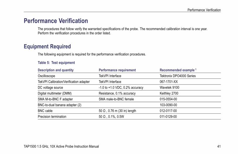
Performance VerificationThe procedures that follow verify the warranted specifications of the probe. The recommended calibration interval is one year.Perform the verification procedures in the order listed.
Equipment RequiredThe following equipment is required for the performance verification procedures.
Table 5: Test equipment
Description and quantity Performance requirement Recommended example 1
Oscilloscope TekVPI Interface Tektronix DPO4000 SeriesTekVPI Calibration/Verification adapter TekVPI Interface 067-1701-XXDC voltage source -1.0 to +1.0 VDC, 0.2% accuracy Wavetek 9100Digital multimeter (DMM) Resistance, 0.1% accuracy Keithley 2700SMA M-to-BNC F adapter SMA male-to-BNC female 015-0554-00BNC-to-dual banana adapter (2) 103-0090-00BNC cable 50 Ω , 0.76 m (30 in) length 012-0117-00Precision termination 50 Ω , 0.1%, 0.5W 011-0129-00
TAP1500 1.5 GHz, 10X Active Probe Instruction Manual 41

Performance Verification
Table 5: Test equipment (cont.)
Description and quantity Performance requirement Recommended example 1
Y-Lead adapter 0.25-in square pins for probe tipconnections
196-3463-xx 2
SMT KlipChip adapters (2) 0.25-in square pins-to-mini clips 206-0364-xx 2
1 Nine-digit part numbers (xxx-xxxx-xx) are Tektronix part numbers.2 Standard accessories included with the probe.
42 TAP1500 1.5 GHz, 10X Active Probe Instruction Manual

Performance Verification
Equipment SetupUse the following procedure to set up and warm up the equipment to test the probe.
1. Turn on the oscilloscope.
2. Connect the TekVPI Calibration/Verificationadapter to the oscilloscope.
3. Connect the probe to the TekVPICalibration/Verification adapter and verifythat the Status LED on the probe turnsgreen.
4. Turn on the remaining test equipment.
5. Allow 20 minutes for the equipment towarm up.
6. Photocopy the test record and use it torecord the test results. (See page 47, TestRecord.)
TAP1500 1.5 GHz, 10X Active Probe Instruction Manual 43

Performance Verification
DC Gain AccuracyThis test checks the DC gain accuracy of the probe.
1. Connect the BNC-to-dual banana adapterto the DMM input.
2. Connect the SMA M-to-BNC F adapterto the SMA output of the TekVPICalibration/Verification adapter.
3. Connect the precision termination to theBNC end of the SMA M-to-BNC F adapter.
4. Connect the BNC cable between theprecision termination and the BNC-to-dualbanana adapter attached to the DMM.
44 TAP1500 1.5 GHz, 10X Active Probe Instruction Manual

Performance Verification
5. Connect the second BNC-to-dual bananaadapter to the output of the DC voltagesource.
6. Connect the Y-lead adapter and KlipChipadapters to the probe input.
7. Attach the KlipChip adapters to theBNC-to-dual banana adapter connectedto the DC voltage source. Make sure thepolarity is correct-ground to outer shieldand probe input to center conductor.
TAP1500 1.5 GHz, 10X Active Probe Instruction Manual 45

Performance Verification
8. Set oscilloscope probe offset to 0.0 V.
9. Set the DMM to DCV.
10. Set the DC voltage source to +1.00 VDCand enable the output.
11. Record the DMM measurement in the testrecord.
12. Set the DC voltage source to -1.00 VDC.
13. Record the DMM measurement in the testrecord.
NOTE. An unacceptable error value mayresult if a precision 50 Ω termination is notused for the recommended termination, or ifthe oscilloscope probe offset is not set to zero.
46 TAP1500 1.5 GHz, 10X Active Probe Instruction Manual

Performance Verification
Test RecordProbe Model/Serial Number:Temperature:Date of Calibration:
Certificate Number:RH %:Technician:
Performancetest
Source voltage Minimum Measured Calculated Maximum
+1.00 VDC +98 mV NA +102 mVDC GainAccuracy -1.00 VDC -102 mV NA -98 mV
TAP1500 1.5 GHz, 10X Active Probe Instruction Manual 47

Maintenance
MaintenanceThis section contains maintenance information for your probe.
Error ConditionThe TAP1500 active probe is designed to work with all TekVPI-interface oscilloscopes and adapters. However, there may be somecases where all of the probe features may not work properly.
If the Status LED glows red during or after probe power on, an internal probe diagnostic fault exists. Disconnect and reconnect theprobe to restart the power-on diagnostic sequence. If the Status LED continues to glow red, the probe is defective, and mustbe returned to Tektronix for repair.
Replacement PartsThere are no user replaceable parts within the probe. Refer to Accessories for a list of replaceable accessories for your probe.
48 TAP1500 1.5 GHz, 10X Active Probe Instruction Manual

Maintenance
CleaningProtect the probe from adverse weather conditions. The probe is not waterproof.
CAUTION. To prevent damage to the probe, do not expose it to sprays, liquids, or solvents. Avoid getting moisture insidethe probe during exterior cleaning.
Do not use chemical cleaning agents; they may damage the probe. Avoid using chemicals that contain benzine, benzene,toluene, xylene, acetone, or similar solvents.
Clean the exterior surfaces of the probe with a dry, lint-free cloth or a soft-bristle brush. If dirt remains, use a soft cloth or swabdampened with a 75% isopropyl alcohol solution. A swab is useful for cleaning narrow spaces on the probe, use only enoughsolution to dampen the swab or cloth. Do not use abrasive compounds on any part of the probe.
TAP1500 1.5 GHz, 10X Active Probe Instruction Manual 49

Maintenance
50 TAP1500 1.5 GHz, 10X Active Probe Instruction Manual

Index
IndexAAccessories
optional, 22standard, 13
Autozero, 5
CCleaning the probe, 49Connecting the probe, 2
DDC gain accuracy
performance check, 44Documentation, viii
EError condition, 48
FFeatures, 1Functional check, 6
GGround lead
inductance, 26selecting length, 25
IIndicators, 3
LLED
Status, 3
MMaintenance, 48Menu Button, 4
OOffset, 11Options, 24
PPerformance verification, 41
equipment required, 41equipment setup, 43
Probe controls and indicators, 3Probe head, 9
RRelated documentation, viiiReplacement parts, 48
SSafety Summary, iiiSpecifications, 31
nominal, 40typical, 33warranted, 32
Status LED, 3, 48
TTekVPI, 2Test record, 47
TAP1500 1.5 GHz, 10X Active Probe Instruction Manual 51