Tank Tread Tutorial - iRoboticsirobotics.illinois.edu/w/images/5/52/TANKTREAD_GUIDE.pdf · This...
30
Tank Tread Tutorial Irobotics µTAN(CLAN)
Transcript of Tank Tread Tutorial - iRoboticsirobotics.illinois.edu/w/images/5/52/TANKTREAD_GUIDE.pdf · This...

Tank Tread Tutorial
Irobotics µTAN(CLAN)

1
Steps 1. Preface .................................................................................................................................................. 3
2. Prepare the Link .................................................................................................................................... 4
A. Open the link ..................................................................................................................................... 4
B. Create two axis through the link ....................................................................................................... 4
C. Create plane: through two lines (Work Plane 1) .............................................................................. 4
D. Create 2D Sketch on the Work Plane 1 ............................................................................................. 5
E. Create Work Point at the sketch point, rename the point to ‘Center’ ............................................. 7
F. Turn off the visibility of everything except the model ...................................................................... 8
G. Save and close the link ...................................................................................................................... 8
3. Create the Assembly File and Save ....................................................................................................... 8
4. Place the sprockets ............................................................................................................................... 8
5. Create Path File ..................................................................................................................................... 9
A. Click Create ....................................................................................................................................... 9
B. Name the component and choose the template .............................................................................. 9
C. Choose ‘Reference’ for the BOM structure ...................................................................................... 9
D. Click Ok ............................................................................................................................................ 10
E. Click anywhere on the screen to place and create part ................................................................. 10
F. Save (Ctrl+s) .................................................................................................................................... 10
6. Import Dimension from Link ............................................................................................................... 10
A. Go to Parameters ............................................................................................................................ 10
B. Click ‘Link’ ........................................................................................................................................ 10
C. Change file of type to inventor files, and open the link part file .................................................... 10
D. Click and derive the dimension ‘LinkLength’, click Done ................................................................ 11
7. Draw the Path ..................................................................................................................................... 12
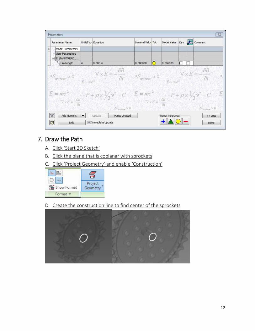
A. Click ‘Start 2D Sketch’ ..................................................................................................................... 12
B. Click the plane that is coplanar with sprockets .............................................................................. 12
C. Click ‘Project Geometry’ and enable ‘Construction’ ....................................................................... 12
D. Create the construction line to find center of the sprockets ......................................................... 12
E. Create the construction point to find the center of the sprocket teeth ........................................ 13
F. Disable the construction ................................................................................................................. 14
G. Draw the Path ................................................................................................................................. 14
H. Create reference dimension of the path ........................................................................................ 15

2
I. Finish the sketch ............................................................................................................................. 15
J. Open Parameters ............................................................................................................................ 15
K. Add Numeric User Parameters for ‘Circumference’ ....................................................................... 16
L. Click Done ....................................................................................................................................... 16
8. Create Point Pattern ........................................................................................................................... 16
A. Add point on the path ..................................................................................................................... 16
B. Pattern the work point .................................................................................................................... 16
C. Return to the top assembly ............................................................................................................ 21
9. Constrain the Path .............................................................................................................................. 21
10. Place the Link .................................................................................................................................. 22
A. Click place, select the chain/tread link, and place on the screen ................................................... 22
B. Expand the model tree for Path and Link ....................................................................................... 22
C. Using Constrain, mate the ‘Center’ from the Link to ‘Work Point’ on the Path ............................. 23
D. Turn the visibility of the sketch of path .......................................................................................... 23
E. Create tangent constraint between Work Plane of the link and the arc path ............................... 23
F. Turn off the visibility of the path sketch ......................................................................................... 24
G. Constrain (flush) the vertical plane of the link with the plane of the path .................................... 24
H. Change the model tree from ‘Assembly View’ to ‘Modeling View’ ................................................ 25
I. Create Link Pattern around the path .............................................................................................. 25
11. Capability and limitation of this method ........................................................................................ 27
A. Capability ........................................................................................................................................ 27
B. Limitation ........................................................................................................................................ 28
12. Tip.................................................................................................................................................... 29

3
1. Preface This guide is written for intermediate user of Autodesk Inventor, but the steps should be easy to
follow if you know the basics of the inventor. For the tutorial, VEX tank tread and sprockets were used,
but the method can be used for any other chain or tread application. The ultimate objective of this guide
is to show you and teach some advanced way of patterning components or features, and using adaptive
drawing/part to create modifiable tread assembly. If you have any problem, question, or suggestion, feel
free to contact me.

4
2. Prepare the Link
A. Open the link
(VEX-LINK-BASE for example)
B. Create two axis through the link
C. Create plane: through two lines (Work Plane 1)

5
D. Create 2D Sketch on the Work Plane 1
i. Click ‘Start 2D Sketch’
ii. Click Work Plane 1 on the Model Tree
iii. Click ‘Project Geometry’ and ‘Construction’
iv. Click two axis and two surface on the top
v. Right-click & hold the mouse, click Ok. (or esc)
vi. Create a point and two dimensions
vii. Create reference dimension

6
viii. Set the point in the middle (Click the reference dimension and divide it by 2)
ix. Go to ‘Parameters’ (Manage – Parameters)

7
x. Rename the distance between the axis (reference parameter d3, for example) to
‘LinkLength’
xi. Click ‘Export Parameter’
xii. Click Done
xiii. Double click the reference dimension and check the name
xiv. Finish Sketch
E. Create Work Point at the sketch point, rename the point to ‘Center’

8
F. Turn off the visibility of everything except the model
G. Save and close the link
3. Create the Assembly File and Save
4. Place the sprockets It is arbitrary: it depend on the design of the tread.
i. Align all the sprocket in the same plane. (If necessary, make the work plane on the
sprocket part file)
ii. Ground one of the sprocket

9
5. Create Path File
A. Click Create
B. Name the component and choose the template
(Choose .ipt, standard inventor part extension, for the template)
C. Choose ‘Reference’ for the BOM structure
Note: This part file will be used as a reference to make the tread, therefore it
should not be included in the BOM list.

10
D. Click Ok
E. Click anywhere on the screen to place and create part
F. Save
6. Import Dimension from Link
A. Go to Parameters
B. Click ‘Link’
C. Change file of type to inventor files, and open the link file
(VEX-LINK-BASE for example)

11
D. Click and derive the dimension ‘LinkLength’, click Done
12
7. Draw the Path
A. Click ‘Start 2D Sketch’ B. Click the plane that is coplanar with sprockets
C. Click ‘Project Geometry’ and enable ‘Construction’
D. Create the construction line to find center of the sprockets

13
E. Create the construction point to find the center of the sprocket teeth
Notice: Adaptive is enabled for the Path file.

14
F. Disable the construction
G. Draw the Path
(Make sure to have tangent constrain between arc (or circle) and lines.)

15
H. Create reference dimension of the path
Note: While dimensioning, you can change the type of dimension (ex. aligned, arc length) by right-click.
I. Finish the sketch
J. Open Parameters

16
K. Add Numeric User Parameters for ‘Circumference’
L. Click Done
8. Create Point Pattern
A. Add point on the path
B. Pattern the work point
i. Click Rectangular Pattern

17
ii. Click Work Point on the model tree for Features
iii. Select Direction 1 (Click and click the path sketch)
Notice the green arrow for the direction. You can flip the direction with
iv. Change ‘Spacing’ to ‘Curve Length’

18
v. Type ‘Circumference/LinkLength’ for spacing
vi. Open detail settings

19
vii. Change the starting point of the direction 1 to the work point
(Click and click Work Point on the Model Tree)
viii. Change Compute to ‘Adjust’, and change Orientation to ‘Direction1’
ix. Click Ok

20
x. Open the Parameters
xi. Change the tolerance of d10(number of link) to less
xii. Click Done

21
C. Return to the top assembly
9. Constrain the Path i. Click the plane with the points, and turn on the visibility.
ii. Find the parallel plane on the grounded sprocket, and turn on the visibility
iii. Constrain using Flush

22
iv. Turn off the visibility
10. Place the Link
A. Click place, select the chain/tread link, and place on the screen
B. Expand the model tree for Path and Link

23
C. Using Constrain, mate the ‘Center’ from the Link to ‘Work Point’ on the Path
D. Turn the visibility of the sketch of path
E. Create tangent constraint between Work Plane of the link and the arc path

24
-
-
F. Turn off the visibility of the path sketch
G. Constrain (flush) the vertical plane of the link with the plane of the path

25
-
-
If this constraint gives an error, it means sprocket, path, or link are not aligned.
H. Change the model tree from ‘Assembly View’ to ‘Modeling View’
I. Create Link Pattern around the path
i. Click Pattern

26
ii. Click the link for the Component
iii. Click the rectangular pattern in the Path for ‘Feature Pattern Select’
Note: If you don’t see the patter, make sure you change the model tree to ‘Modeling View.’ (step 10.H)
iv. Click Ok
27
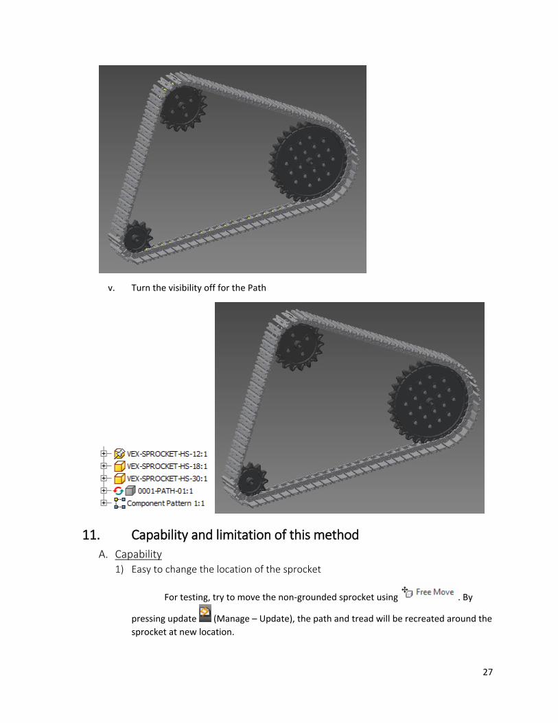
v. Turn the visibility off for the Path
11. Capability and limitation of this method
A. Capability
1) Easy to change the location of the sprocket
For testing, try to move the non-grounded sprocket using . By
pressing update (Manage – Update), the path and tread will be recreated around the
sprocket at new location.

28
This is because of the Path is ‘adaptive,’ and the pattern is completely depend
on the path file. The adaptive drawing is referencing the location of the sprocket, which
is why moving the sprocket will regenerate the path drawing.
This feature is useful when the length/shape of the tread is not yet defined, but
still want to construct a CAD file that can be adapted to any design.
2) Reduced amount of computation
In the Autodesk Inventor, the main reason of slowing down the computer is
because of constrain. Every single constrain is calculated in the matrix to find the
location and orientation of each part. In this case, or any other chain/tread example, if
each link of chain or tread takes 3 constrain to be fixed at some location, the amount of
computation increases exponentially. This method only constrain one link to the point,
and all other parts are copied by the pattern, which reduces the amount of calculation
significantly.
3) Presentation
Visually, it creates almost perfect linkage around the path. The limitation usually
comes when the curvature of arc is too large.
4) No limit on the number of sprocket
B. Limitation
1) No Constrain
Since all the chains are held without constrain, any mechanical and static/stress
analysis are impossible to do in the software. Also, technically parts are not held
together.
2) No Animation
Practically, there is no easy way of making tread moving animation in the
inventor in this way. It is possible to make a fake animation, or make it seems to be

29
moving around the path, which is not included in this guide, but it is impossible to make
the tread to actually move around the path. (If you really want to make one, try to move
the starting point around the path)
12. Some Tip 1) Don’t include any other component in the tread assembly, and only keep
sprockets, path, and link on the assembly.
a. Include shaft, motor, support, or any other parts in the parent assembly
file, and use this tread assembly as a sub-assembly from the parent
assembly.
2) Turn the additivity of the path off when it is not in use: it takes more computation
to calculate adaptive part or features.