Math Cookies-Group 4 Done By: Alastair Loh Toh Yong Han Tang Wei Khong Tnay Chong Kiang.
Upload
phungxuyenCategory
view
214download
1
AUTOMOTIVE ENGINE CFD - PAST, PRESENT &
THE FUTURE
ERC - 2017 SymposiumJune 14 th & 15 th, 2017
Tang-Wei KuoGeneral Motors Global Research and Development

ABSTRACT
Role of computational tools in propulsion system
development has increased dramatically over the past
several decades and continues to evolve. At General
Motors, use of advanced predictive tools is at the core
of its corporate Road to Lab to Math strategy. This
talk provides an overview of the state of automotive
engine CFD from an OEM perspective with supporting
examples. Finally, the desired roadmap for improved
accuracy and increased use of these tools is presented.

OUTLINE
• How far has engine CFD evolved over the years?
• Examples of GM’s application of Engine CFD
Institutionalize standard work procedures
Improve predictive capability
• Desired future roadmap

INITIAL WAVE OF ENGINE CFD (PRIOR TO 1990)
Sample Sources of CFD Codes & Validation Data:
• Fluid Dynamics Group T-3 at the Los Alamos
National Laboratory (USA)
• Prof. D. B. Spalding at Imperial College (London)
• Prof. F. V. Bracco at Princeton University (USA)
• CRF at the Sandia National Lab (USA)
CFD Codes:
• CONCHAS, CONCHAS-Spray, KIVA
(LANL)
• PHOENICS (CHAM Ltd.)
• FIDAP (Fluid Dynamics International)
• Fluent (Creare Inc.)
• Star-CD (CD-ADAPCO)
National Labs
• Base Architecture
• Code Integration
• Validation Data
Universities
• Training of New User Base
• Birth of commercial CFD companies
Common
Sharing
Source - The Three Waves of Commercial CFD - Mentor Graphics

CFD CAPABILITIES DURING THE INITIAL WAVE
• Limited Computer Hardware –limited model sizes and
resolution
• Structured Finite Volume Methods – difficult to handle
complex geometry and optimize for HPC
• Numerical Methods not available to handle moving
boundaries like valves
• Emphasis is on physical models development and application
Industry remained speculative on usage of CFD toolset

SECOND WAVE OF ENGINE CFD (1990-2000)
National Labs
• Base Architecture
• Code Integration
• Validation Data
Industry
• Research & Development
• Critical Feedback
• Proprietary Sub-models & Best Practices
Universities
• Sub-model Development
• Code Proliferation
• Training of New User Base
Common
Platform
Commercial
CFD
Vendors
Working relationship
1. Centered around a common code
platform
2. Each entity had particular strengths
3. Strong user community and open
communication
Driven By …..
1. Growth in Computer Hardware –
realistic model sizes became
possible
2. Advance in Numerical Methods –
handled complex geometry with
moving interfaces and optimized for
HPC
3. Reliable and Robust Physical
Models became Commercially
Available
4. Growth of Commercial Codes - User
support, code maintenance & usage
(GUI)

THIRD WAVE OF ENGINE CFD (SINCE 2000)
Industry
Universities
National Labs
COTS1
COTS2
OpenSrc1
UDF1
COTS3
UDF2
COTS4
UDF3
OpenSrc2
COTS5
Current Landscape
1. Institutions centered
around a growing
‘web’ of commercial
(COTS) and open
source options
2. Implementing UDFs
into commercial
codes with limited/no
validation
3. Growth of open
source codes in
industry hampered
by liability and user
support UDF4

OUTLINE
• How far has engine CFD evolved over the years?
• Examples of GM’s application of Engine CFD
Institutionalize standard work procedures
Improve predictive capability
• Desired future roadmap
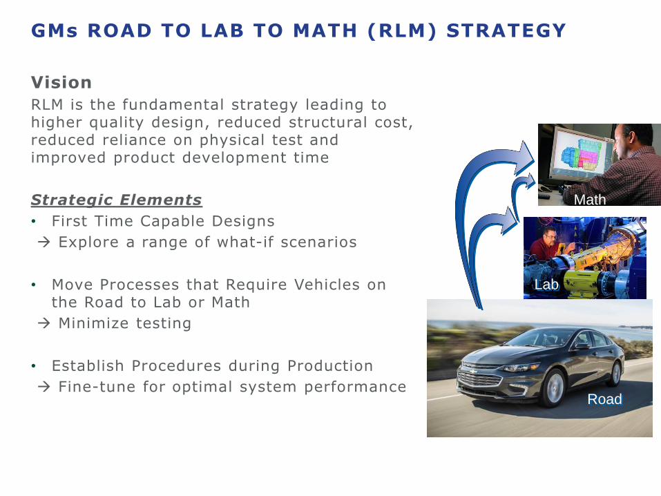
GMs ROAD TO LAB TO MATH (RLM) STRATEGY
Vision
RLM is the fundamental strategy leading to higher quality design, reduced structural cost, reduced reliance on physical test and improved product development time
Strategic Elements
• First Time Capable Designs
Explore a range of what-if scenarios
• Move Processes that Require Vehicles on the Road to Lab or Math
Minimize testing
• Establish Procedures during Production
Fine-tune for optimal system performance
Lab
Math
Road

SPRAY PATTERN OPTIMIZATION
Spray Pattern Definition:Target at 30 mm down stream
Automatically generated by optimizer
Goal:
• Find optimum injector for a
given combustion system to
achieve– Better few economy
– Lower emission
Baseline Optimized

EXPERIMENTAL CONFIRMATION
Measured Particulate Count
during FTP Test
Measured Combustion efficiency
at 2000 RPM 6 bar
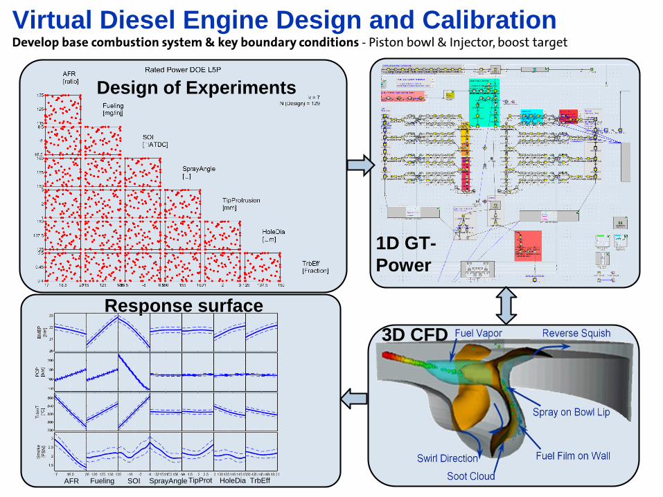
Virtual Diesel Engine Design and Calibration Develop base combustion system & key boundary conditions - Piston bowl & Injector, boost target
1D GT-
Power
3D CFD
Response surface
AFR Fueling SOI SprayAngleTipProt HoleDia
Design of Experiments
TrbEff

Virtual Diesel Engine Design and Calibration Develop base combustion system & key boundary conditions - Piston bowl & Injector, boost target
Source - The first of a new generation of diesel engines from General Motors – the efficient and powerful 1.6
liter Euro6 Midsize Diesel Engine, 34th Vienna Motor Symposium, 2013
Overall Integration of Activity
Nodes employed by genetic Algorithm Evolution of Merit Function

OUTLINE
• How far has engine CFD evolved over the years?
• Examples of GM’s application of Engine CFD
Institutionalize standard work procedures
Improve predictive capability
• Desired future roadmap

CFD MODELS STILL REQUIRE FURTHER IMPROVEMENT
1. Large range in spatial scales drives need for accurate sub-models
PFIDiesel, SIDI drops
Human hair10000
Engine
BoreMesh
Size
2. Must account for millions of spray droplets15 mg gasoline:
# of Drops Radius A/V
1: 1.68mm 2
11,300,000: 7.5mm 400
3. Extremely challenging in-cylinder environment (for both models and measurements)
Turbulent Flow Ignition, Combustion & EmissionsDense Spray Effects
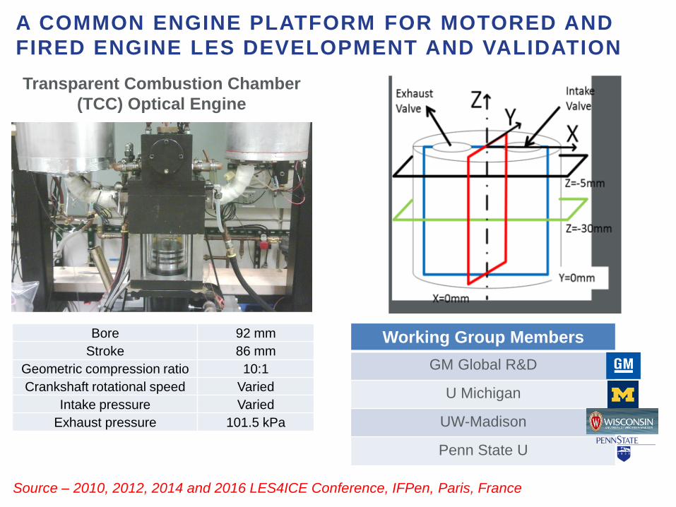
A COMMON ENGINE PLATFORM FOR MOTORED AND
FIRED ENGINE LES DEVELOPMENT AND VALIDATION
Bore 92 mm
Stroke 86 mm
Geometric compression ratio 10:1
Crankshaft rotational speed Varied
Intake pressure Varied
Exhaust pressure 101.5 kPa
Transparent Combustion Chamber
(TCC) Optical Engine
Working Group Members
GM Global R&D
U Michigan
UW-Madison
Penn State U
Source – 2010, 2012, 2014 and 2016 LES4ICE Conference, IFPen, Paris, France

TCC engine is simulated by an increasing number
of research groups
Data access managed by GM R&D and UM
Multiplying effect: research output for GM &
visibility
A COMMON ENGINE PLATFORM FOR MOTORED AND
FIRED ENGINE LES DEVELOPMENT AND VALIDATION
Maps.google.com
GM sponsored
Not GM sponsored

IN-CYLINDER FLOWS USING LARGE EDDY SIMULATION (LES ) -
PROPOSED STRATEGY FOR FASTER LES RESULTS
• Source - “Parallel Methodology to Capture Cyclic Variability in Motored Engines,” International Journal of
Engine Research, Vol. 18, No. 4, April, 2017.
Each parallel simulation starts from the
top dead center of compression. At this
crank angle, both valves are closed
and the turbulence is almost
homogenous.
The mapped initial condition is
obtained from the velocity field at the
end of cycle 2.
The initial conditions for each of the
parallel simulations is obtained by
adding synthetic turbulent flow fields to
the mapped initial condition
The length scales and velocity scales
of this synthetic field is determined
based on the PIV dataset at TDC

PARALLEL VS CONSECUTIVE LES
Parallel LES Consecutive LES
19
MEAN
RMS

NEAR-TIP INTERNAL-TO-EXTERNAL NOZZLE FLOW COUPLING
6.6
mm
1.0
mm
Velocity profileNear Field Imaging
Internal Flow simulations
Spray Plumes
Phase 1
OLCF DD
Project
Phase 2
ALCC
Project
6-hole Injector
External Spray Simulations
3mm
TOTAL CELL COUNT: 7,564,828
0.375 mm
70
mm
Injector flow coupling
CONVERGE™ External Spray Simulations
Customized UDF to read-in nozzle internal
flow velocity profile from HRMFoam
simulations
Fixed mesh embedding to resolve the
propagation of the spray
Semi-empirical injection routine
Droplets injected post primary
atomization
Collision & Coalescence model turned
OFF
HRMFoam
104 mm
Source – ALCC CMB-107

EXTERNAL SPRAY SIMULATION RESULTS
Spray collapse driven by increase in plume-to-plume
interaction
Pa=40kPa Tfuel=85C
Pa=40kPa Tfuel=25COn-axis View
0.5 msSource - DOE Annual Merit Review (ACE017)

STEADY STATE CALIBRATION FOR DIESEL ENGINES USING
GENERAL PURPOSE GPU ENABLED CFD TOOLS
GT-Power
CFD
Virtual Engine Model 1-D GT-Power model to predict multi-cylinder
engine performance
3-D CFD to predict heat release and emissions• Reliable prediction of in-cylinder spray, mixture
formation and combustion
Engine testing & Calibration
using Statistical Methods Methodology and constraints similar
to real engine hardware
Virtual Map for Vehicle SimulationSource – ALCC CMB-119
Controlling Parameters
Engin
e P
erf
orm
ance

STEADY STATE CALIBRATION FOR DIESEL ENGINES USING
GENERAL PURPOSE GPU ENABLED CFD TOOLS
• CFD model predictions trend similarly to experimental validation measurements− Excellent in combustion metrics
− Reasonably good for NOx and Soot
− CO and unburn HC predictions are much worse− Highly detailed kinetic mechanism (>1,000 species) + multi-component surrogate to improve
prediction accuracy (investigation in progress)
Excellent
Good
Poor
OUTLINE
• How far has engine CFD evolved over the years?
• Examples of current applications
• Desired future roadmap

WHAT DOES THE FUTURE HOLD?
Fundamental Numerics
• Higher order robust schemes
• Exascale computing
• Fast meshing
• ALE parallelization
• Mesh independence
• Assessment of GPUs
Advanced Sub-models
Product
Development
• Flows (LES, Cyclic variability)
• Sprays (Nozzle flows, atomization, etc.)
• Chemistry (emission, TCI, kinetics, etc.)
Pre
-Co
mp
etitiv
eP
rop
rieta
ry
• Workflows
• In-house validation
• User Interface
Software vendor
implementation or UDF
• Publication
• Source Code
Source - The Role of VTO on Development of Advanced CFD Codes in support of DOE Advanced Combustion
Engine Efficiency Goals, DOE VTO Workshop, August 18, 2014

Desired Roadmap
1-2 day
turnaround
(future roadmap)
• Multi-cycle LES, cyclic variability
• Resolution of dense spray region
• Large kinetic mechanisms
• Fast flow & chemistry solvers
• Mesh independence
• Optimization
Desired pathway for enhanced solver
scalability to enable high-fidelity simulations
with acceptable turnaround time
ENHANCED SCALABILITY TOWARDS PREDICTIVE
SIMULATIONSS
ub
-mo
de
l d
eve
lop
me
nt
1cpu ~10’s cpus ~100’s cpus LCF
• Single Cycle RANS
• Empirical spray and
combustion
• Reduced chemistry
• Extensive trial and error
Restricted to large number of
simultaneous simulations on
LCF Platforms
Present status

Rules of Engagement
Pre-competitive
National Labs Universities
Software Vendors
Industrial R&D
Product Teams(Engine Design)
Industry R&D groups will use the tools to generate design guidelines and calculation metrics for design
optimization by Product Teams
Limited interactions• User training• User defined functions• Software support incl.
—GUI—Debugging—Post processing—Application support
Limited interactions between Universities and software vendors preferred• Help implement
physical submodels
Source - Leveraging National Laboratory Computing Resources to Improve IC Engine Simulation, ANL VERIFI
Workshop, June 22-23, 2016