TANDEM SYSTEM PLUMBING KIT - edc.poolsupplyworld.com · tandem system plumbing kit page 3 read and...
8
® TANDEM SYSTEM PLUMBING KIT INSTALLATION, OPERATION & SERVICE MANUAL ® PENTAIR POOL PRODUCTS CORPORATE OFFICE Sanford, NC (919) 566-8000 PENTAIR POOL PRODUCTS Moorpark, CA (805) 523-2400 P/N 152992 REV. A
Transcript of TANDEM SYSTEM PLUMBING KIT - edc.poolsupplyworld.com · tandem system plumbing kit page 3 read and...

® TANDEM SYSTEM PLUMBING KITINSTALLATION, OPERATION & SERVICE MANUAL
®
PENTAIR POOL PRODUCTSCORPORATE OFFICE
Sanford, NC(919) 566-8000
PENTAIR POOL PRODUCTSMoorpark, CA
(805) 523-2400 P/N 152992 REV. A
®
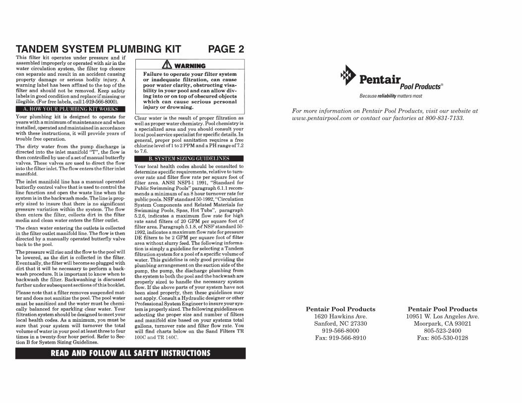
For more information on Pentair Pool Products, visit our website atwww.pentairpool.com or contact our factories at 800-831-7133.
Pentair Pool Products1620 Hawkins Ave.Sanford, NC 27330
919-566-8000Fax: 919-566-8910
Pentair Pool Products10951 W. Los Angeles Ave.
Moorpark, CA 93021805-523-2400
Fax: 805-530-0128
TANDEM SYSTEM PLUMBING KIT PAGE 2
READ AND FOLLOW ALL SAFETY INSTRUCTIONS

TANDEM SYSTEM PLUMBING KIT PAGE 3
READ AND FOLLOW ALL SAFETY INSTRUCTIONS
2 TR100 Cor
2 TR100 C3
3 TR100 Cor
3 TR100 C3
4 TR100 Cor
4 TR100 C3
5 TR100 Cor
5 TR100 C3
2 TR140 Cor
2 TR140 C3
3 TR140 Cor
3 TR140 C3
4 TR140 Cor
4 TR140 C3
5 TR140 Cor
5 TR140 C3
6 TR140 Cor
6 TR140 C3
TANDEM TRITON II TR 100 C & TR 100 C3 FILTER INSTALLATION
TANDEM TRITON II TR 140 C & TR 140 C3 FILTER INSTALLATIONNOTES

TANDEM SYSTEM PLUMBING KIT PAGE 4
READ AND FOLLOW ALL SAFETY INSTRUCTIONS
NUMBER OFFILTERS KIT # QTY. KIT # QTY. KIT # QTY.
C C-3” C C-3” C C-3”
2 FILTERS 14-6400 14-7400 1 14-6402 14-7402 1
14-6402 14-7402 1 14-6404 14-7404 13 FILTERS
14-6406 14-7406 1 14-6408 14-7408 1
14-6402 14-7402 1 14-6404 14-7404 14 FILTERS
14-6406 14-7406 2 14-6408 14-7408 2
14-6404 14-7404 15 FILTERS
14-6408 14-7408 3
14-6404 14-7404 16 FILTERS
14-6408 14-7408 4
3” 4” 6”
MANIFOLD SIZE SCH 40
NUMBER OFFILTERS KIT # QTY. KIT # QTY. KIT # QTY.
C C-3” C C-3” C C-3”
2 FILTERS 14-6401 14-7401 1 14-6403 14-7403 1
14-6403 14-7403 1 14-6405 14-7405 13 FILTERS
14-6407 14-7407 1 14-6409 14-7409 1
14-6403 14-7403 1 14-6405 14-7405 14 FILTERS
14-6407 14-7407 2 14-6409 14-7409 2
14-6405 14-7405 15 FILTERS
14-6409 14-7409 3
14-6405 14-7405 16 FILTERS
14-6409 14-7409 4
3” 4” 6”
MANIFOLD SIZE SCH 80
NOTES
READ AND FOLLOW ALL SAFETY INSTRUCTIONSREAD AND FOLLOW ALL SAFETY INSTRUCTIONS
ADDENDUM TANDEM PLUMBING KIT PAGE 51. Check carton for any evidence of damage due
to rough handling in Shipment. If carton orany filter kit components are damaged, notifyfreight carrier immediately.
2. Refer to Filter Manual for details on filterinstallation.
3. The Tandem filter kits have been designed toprovide the maximum flexibility for instal-lation. The installer will supply all the pipingto connect the complete system.
4. It is recommended that the filters be positi-oned in their final location and arranged toallow sufficient service access for each filter.Equal filter spacing is recommended since itsimplifies the installation. Refer to filter tanklabel for minimum filter clearance between fil-ters.
5. Once filters are in position, place about 5 gal-lons of water in the tanks. This will help sta-bilize the filter.
6. It is best to cut all piping and dry assemble thecomplete system prior to making any finalglue joints. This helps to insure that no mis-takes are made in the final system.
You should assemble the tank “T” fittingassemblies first. These are the assemblies thatform the “T” connections that join directly tothe inlet and outlet of the filters – two assem-blies per tank. Follow the instructions for theassemblies that correspond to the size filteryou are installing, either 2-inch or 3-inch.
2–inch Filter Unit “T” Assembly
You will need the following parts from yourinstallation kit.
1. Socket Reducer Tee(either 3x2, 4x2 or 6x2)
2. 2” Spigot x Socket 45° Street Elbow3. 2” Spigot Female Adapter,
Spigot x Female Pipe Thread4. 2” Valve Adapter (P/N 271092)
Use a plastic pipe sealant on the 2” valveadapter male thread and thread into the 2”spigot female adapter making sure to havethe 3-1/2” plastic nut in place over theadapter before doing so. If individual shut offvalves are desired, they can be placed in thislocation. Dry fit the female adapter/valveadapter assembly into the socket end of the 2”spigot x socket 45° elbow. Dry fit spigot end ofthis assembly into the reduced tee port of thereducer tee. These glue joints, which connectsthe “T” to the 45° to the valve adapter, arevery important. Pre-assemble the joints dryand insure that the “T” is aligned. Mark tim-ing marks on the female adapter, the 45°elbow and the “T” to insure proper rea-lign-ment when making the final glue joint. Makethe final glue joint only after you are confi-dent that your alignment is proper.
3–inch Filter Unit “T” AssemblyYou will need the following parts from yourinstallation kit.
1. Socket Tee or Reducer Tee(either 3 tee, 4x3 or 6x3 reducer tee)
2. 3” Spigot x Socket 45° Street Elbow3. 3” Flange, VS, Spigot
Dry fit the spigot end of the 3” Spigot x Socket45° Street Elbow into the tee port of the stan-dard or reducer tee. Dry fit this assemblyonto the spigot nipple of the 3” spigot flange.These glue joints, which connects the “T” tothe 45° to the flange, are very important. Pre-assemble the joints dry and insure that the“T” is aligned. Mark timing marks on theflange, the 45° elbow and the “T” to insureproper rea-lignment when making the finalglue joint. Make the final glue joint only afteryou are confident that your alignment isproper.
Build up all of these “ T” fitting assemblies.There should be two “T” assemblies for eachfilter in your system. Let these assembliesdry completely before continuing.
7. For the 2-inch filter units connect one “T”assembly constructed above to each of the fil-ter bulkhead fittings with the 3-1/2” plasticnut. For the 3-inch filter units connect the “T”
READ AND FOLLOW ALL SAFETY INSTRUCTIONS
TANDEM SYSTEM PLUMBING KIT PAGE 12
17
22
19
23
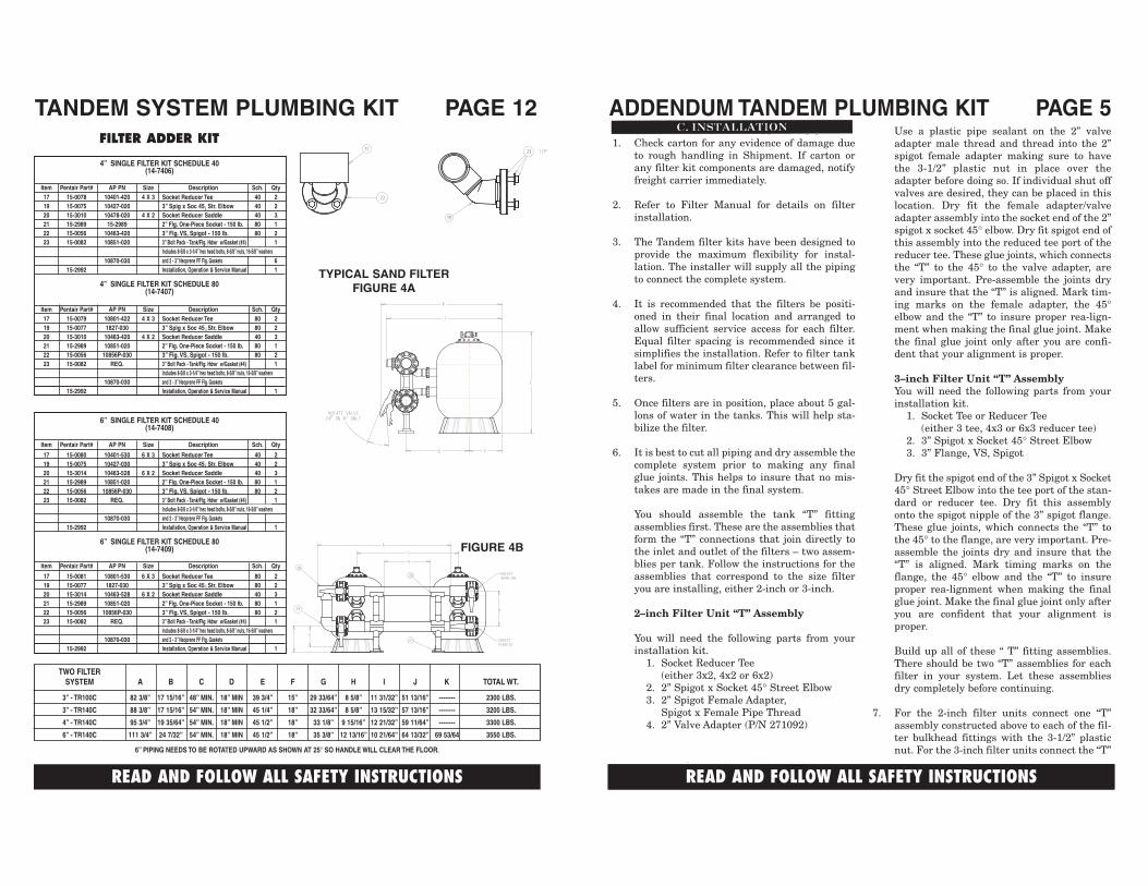
TWO FILTERSYSTEM A B C D E F G H I J K TOTAL WT.
3” - TR100C 82 3/8” 17 15/16” 48” MIN. 18” MIN 39 3/4” 15” 29 33/64” 8 5/8” 11 31/32” 51 13/16” -------- 2300 LBS.
3” - TR140C 88 3/8” 17 15/16” 54” MIN. 18” MIN 45 1/4” 18” 32 33/64” 8 5/8” 13 15/32” 57 13/16” -------- 3200 LBS.
4” - TR140C 95 3/4” 19 35/64” 54” MIN. 18” MIN 45 1/2” 18” 33 1/8” 9 15/16” 12 21/32” 59 11/64” -------- 3300 LBS.
6” - TR140C 111 3/4” 24 7/32” 54” MIN. 18” MIN 45 1/2” 18” 35 3/8” 12 13/16” 10 21/64” 64 13/32” 69 53/64 3550 LBS.
6” PIPING NEEDS TO BE ROTATED UPWARD AS SHOWN AT 25° SO HANDLE WILL CLEAR THE FLOOR.
TYPICAL SAND FILTERFIGURE 4A
18
24
20
21
FIGURE 4B
FILTER ADDER KIT
!!
6” SINGLE FILTER KIT SCHEDULE 40(14-7408)
Item Pentair Part# AP PN Size Description Sch. Qty
17 15-0080 10401-530 6 X 3 Socket Reducer Tee 40 219 15-0075 10427-030 3” Spig x Soc 45 Str. Elbow 40 220 15-3014 10463-528 6 X 2 Socket Reducer Saddle 40 321 15-2989 10851-020 2” Flg. One-Piece Socket - 150 lb. 80 122 15-0056 10856P-030 3” Flg. VS, Spigot - 150 lb. 80 223 15-0082 REQ. 3” Bolt Pack - Tank/Flg. Hdwr w/Gasket (#4) 1
Includes 8-5/8 x 3-1/4” hex head bolts, 8-5/8” nuts, 16-5/8” washers10870-030 and 2 - 3” Neoprene FF Flg. Gaskets
15-2992 Installation, Operation & Service Manual 1
6” SINGLE FILTER KIT SCHEDULE 80(14-7409)
Item Pentair Part# AP PN Size Description Sch. Qty
17 15-0081 10801-530 6 X 3 Socket Reducer Tee 80 219 15-0077 1827-030 3” Spig x Soc 45 Str. Elbow 80 220 15-3014 10463-528 6 X 2 Socket Reducer Saddle 40 321 15-2989 10851-020 2” Flg. One-Piece Socket - 150 lb. 80 122 15-0056 10856P-030 3” Flg. VS, Spigot - 150 lb. 80 223 15-0082 REQ. 3” Bolt Pack - Tank/Flg. Hdwr w/Gasket (#4) 1
Includes 8-5/8 x 3-1/4” hex head bolts, 8-5/8” nuts, 16-5/8” washers10870-030 and 2 - 3” Neoprene FF Flg. Gaskets
15-2992 Installation, Operation & Service Manual 1
!!
4” SINGLE FILTER KIT SCHEDULE 40(14-7406)
Item Pentair Part# AP PN Size Description Sch. Qty17 15-0078 10401-420 4 X 3 Socket Reducer Tee 40 219 15-0075 10427-020 3” Spig x Soc 45 Str. Elbow 40 220 15-3010 10478-020 4 X 2 Socket Reducer Saddle 40 321 15-2989 15-2989 2” Flg. One-Piece Socket - 150 lb. 80 122 15-0056 10463-420 3” Flg. VS, Spigot - 150 lb. 80 223 15-0082 10851-020 3” Bolt Pack - Tank/Flg. Hdwr w/Gasket (#4) 1
Includes 8-5/8 x 3-1/4” hex head bolts, 8-5/8” nuts, 16-5/8” washers10870-030 and 2 - 3” Neoprene FF Flg. Gaskets 6
15-2992 Installation, Operation & Service Manual 1
4” SINGLE FILTER KIT SCHEDULE 80(14-7407)
Item Pentair Part# AP PN Size Description Sch. Qty17 15-0079 10801-422 4 X 3 Socket Reducer Tee 80 219 15-0077 1827-030 3” Spig x Soc 45 Str. Elbow 80 220 15-3010 10463-420 4 X 2 Socket Reducer Saddle 40 321 15-2989 10851-020 2” Flg. One-Piece Socket - 150 lb. 80 122 15-0056 10856P-030 3” Flg. VS, Spigot - 150 lb. 80 223 15-0082 REQ. 3” Bolt Pack - Tank/Flg. Hdwr w/Gasket (#4) 1
Includes 8-5/8 x 3-1/4” hex head bolts, 8-5/8” nuts, 16-5/8” washers10870-030 and 2 - 3” Neoprene FF Flg. Gaskets
15-2992 Installation, Operation & Service Manual 1
1414
13
1516
TANDEM SYSTEM PLUMBING KIT PAGE 11E. PARTS LIST FOR TR 100C3 & 140C3 FILTERS
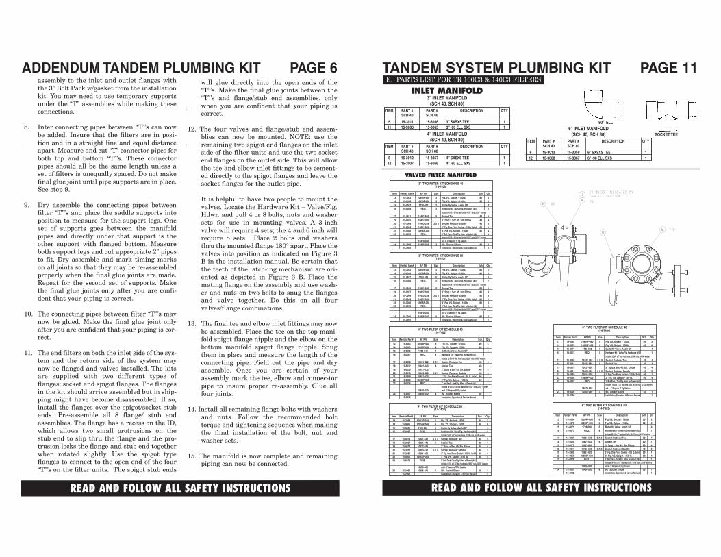
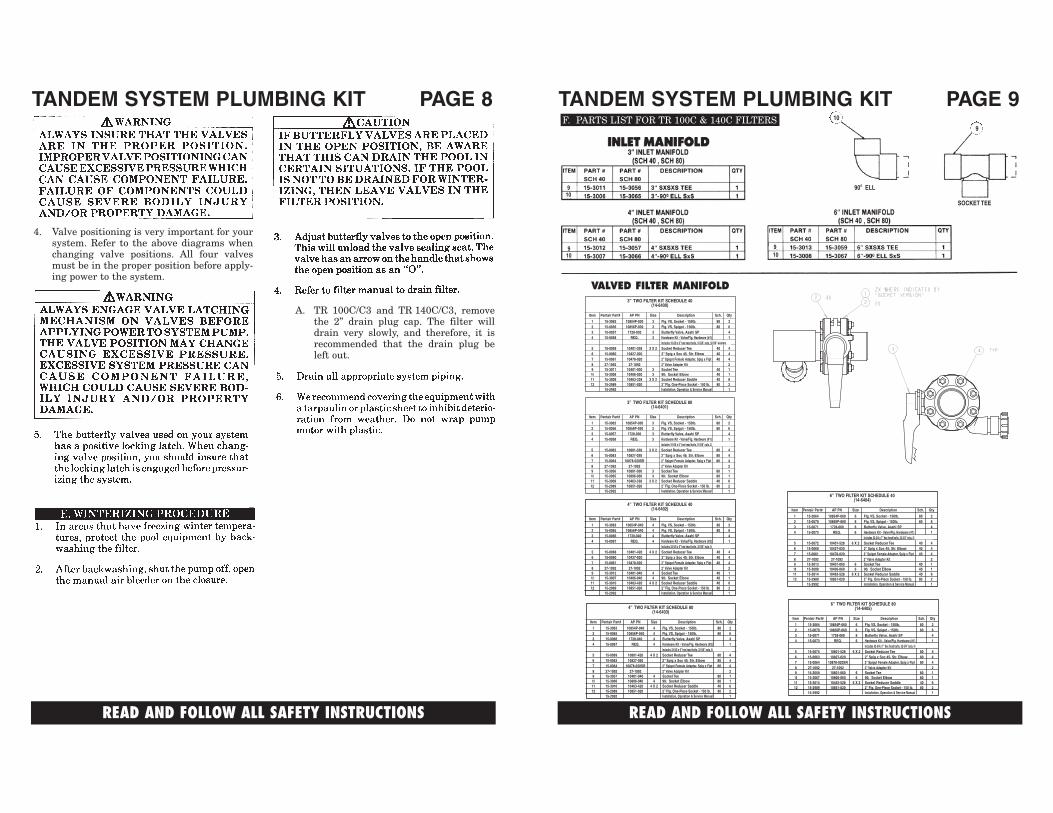
INLET MANIFOLD3” INLET MANIFOLD
(SCH 40, SCH 80)ITEM PART # PART # DESCRIPTION QTY
SCH 40 SCH 80
5 15-3011 15-3056 3” SXSXS TEE 111 15-3006 15-3065 3” -90 ELL SXS 1
4” INLET MANIFOLD(SCH 40, SCH 80)
ITEM PART # PART # DESCRIPTION QTYSCH 40 SCH 80
5 15-3012 15-3057 4” SXSXS TEE 112 15-3007 15-3066 4” -90 ELL SXS 1
6” INLET MANIFOLD(SCH 40, SCH 80)
ITEM PART # PART # DESCRIPTION QTYSCH 40 SCH 80
6 15-3013 15-3059 6” SXSXS TEE 112 15-3008 15-3067 6” -90 ELL SXS 1
READ AND FOLLOW ALL SAFETY INSTRUCTIONS
ADDENDUM TANDEM PLUMBING KIT PAGE 6will glue directly into the open ends of the“T”’s. Make the final glue joints between the“T”’s and flange/stub end assemblies, onlywhen you are confident that your piping iscorrect.
12. The four valves and flange/stub end assem-blies can now be mounted. NOTE: use theremaining two spigot end flanges on the inletside of the filter units and use the two socketend flanges on the outlet side. This will allowthe tee and elbow inlet fittings to be cement-ed directly to the spigot flanges and leave thesocket flanges for the outlet pipe.
It is helpful to have two people to mount thevalves. Locate the Hardware Kit – Valve/Flg.Hdwr. and pull 4 or 8 bolts, nuts and washersets for use in mounting valves. A 3-inchvalve will require 4 sets; the 4 and 6 inch willrequire 8 sets. Place 2 bolts and washersthru the mounted flange 180° apart. Place thevalves into position as indicated on Figure 3B in the installation manual. Be certain thatthe teeth of the latch-ing mechanism are ori-ented as depicted in Figure 3 B. Place themating flange on the assembly and use wash-er and nuts on two bolts to snug the flangesand valve together. Do this on all fourvalves/flange combinations.
13. The final tee and elbow inlet fittings may nowbe assembled. Place the tee on the top mani-fold spigot flange nipple and the elbow on thebottom manifold spigot flange nipple. Snugthem in place and measure the length of theconnecting pipe. Field cut the pipe and dryassemble. Once you are certain of yourassembly, mark the tee, elbow and connec-torpipe to insure proper re-assembly. Glue allfour joints.
14. Install all remaining flange bolts with washersand nuts. Follow the recommended bolttorque and tightening sequence when makingthe final installation of the bolt, nut andwasher sets.
15. The manifold is now complete and remainingpiping can now be connected.
assembly to the inlet and outlet flanges withthe 3” Bolt Pack w/gasket from the installationkit. You may need to use temporary supportsunder the “T” assemblies while making theseconnections.
8. Inter connecting pipes between “T”’s can nowbe added. Insure that the filters are in posi-tion and in a straight line and equal distanceapart. Measure and cut “T” connector pipes forboth top and bottom “T”’s. These connectorpipes should all be the same length unless aset of filters is unequally spaced. Do not makefinal glue joint until pipe supports are in place.See step 9.
9. Dry assemble the connecting pipes betweenfilter “T”’s and place the saddle supports intoposition to measure for the support legs. Oneset of supports goes between the manifoldpipes and directly under that support is theother support with flanged bottom. Measureboth support legs and cut appropriate 2” pipesto fit. Dry assemble and mark timing markson all joints so that they may be re-assembledproperly when the final glue joints are made.Repeat for the second set of supports. Makethe final glue joints only after you are confi-dent that your piping is correct.
10. The connecting pipes between filter “T”’s maynow be glued. Make the final glue joint onlyafter you are confident that your piping is cor-rect.
11. The end filters on both the inlet side of the sys-tem and the return side of the system maynow be flanged and valves installed. The kitsare supplied with two different types offlanges: socket and spigot flanges. The flangesin the kit should arrive assembled but in ship-ping might have become disassembled. If so,install the flanges over the spigot/socket stubends. Pre-assemble all 8 flange/ stub endassemblies. The flange has a recess on the ID,which allows two small protrusions on thestub end to slip thru the flange and the pro-trusion locks the flange and stub end togetherwhen rotated slightly. Use the spigot typeflanges to connect to the open end of the four“T”’s on the filter units. The spigot stub ends
!
!
6” TWO FILTER KIT SCHEDULE 40(14-7404)
Item Pentair Part# AP PN Size Description Sch. Qty
13 15-3064 10854P-060 6 Flg. VS, Socket - 150lb. 80 214 15-0070 10856P-060 6 Flg. VS, Spigot - 150lb. 80 615 15-0071 1728-060 6 Butterfly Valve, Asahi SP 416 15-0073 REQ. 6 Hardware Kit - Valve/Flg. Hardware (#2) 1
Includes 32-3/4” x 7” hex head bolts, 32-3/4” nuts, 64-3/4” washers17 15-0080 10401-530 6 X 3 Socket Reducer Tee 40 418 15-3013 10401-060 6 Socket Tee 40 119 15-0075 10427-030 3” Spig x Soc 45 Str. Elbow 40 420 15-3014 10463-528 6 X 2 Socket Reducer Saddle 40 321 15-2989 10851-020 2” Flg. One-Piece Socket - 150 lb. Solid 80 122 15-0056 10856P-030 3” Flg. VS, Spigot - 150 lb. 80 423 15-0076 REQ. 3” Bolt Pack - Tank/Flg. Hdwr w/Gasket (#4) 1
Includes 16-5/8 x 3-1/4” hex head bolts, 16-5/8” nuts, 32-5/8” washers10870-030 and 4 - 3” Neoprene FF Flg. Gaskets
24 15-3008 10406-060 6 90 Socket Elbow 40 115-2992 Installation, Operation & Service Manual 1
!
!
6” TWO FILTER KIT SCHEDULE 80(14-7405)
Item Pentair Part# AP PN Size Description Sch. Qty
13 15-3064 10854P-060 6 Flg. VS, Socket - 150lb. 80 214 15-0070 10856P-060 6 Flg. VS, Spigot - 150lb. 80 615 15-0071 1728-060 6 Butterfly Valve, Asahi SP 416 15-0073 REQ. 6 Hardware Kit - Valve/Flg. Hardware (#2) 1
Includes 32-3/4” x 7” hex head bolts, 32-3/4” nuts, 64-3/4” washers17 15-0081 10801-530 6 X 3 Socket Reducer Tee 80 418 15-3059 10801-060 6 Socket Tee 80 119 15-0077 10827-030 3” Spig x Soc 45 Str. Elbow 80 420 15-3014 10463-528 6 X 2 Socket Reducer Saddle 40 321 15-2989 10851-020 2” Flg. One-Piece Socket - 150 lb. Solid 80 122 15-0056 10856P-030 3” Flg. VS, Spigot - 150 lb. 80 423 15-0076 REQ. 3” Bolt Pack - Tank/Flg. Hdwr w/Gasket (#4) 1
Includes 16-5/8 x 3-1/4” hex head bolts, 16-5/8” nuts, 32-5/8” washers10870-030 and 4 - 3” Neoprene FF Flg. Gaskets
24 15-3067 10406-060 6 90 Socket Elbow 80 115-2992 Installation, Operation & Service Manual 1
!
!
4” TWO FILTER KIT SCHEDULE 80(14-7403)
Item Pentair Part# AP PN Size Description Sch. Qty
13 15-3063 10854P-040 4 Flg. VS, Socket - 150lb. 80 214 15-0065 10856P-040 4 Flg. VS, Spigot - 150lb. 80 615 15-0066 1728-040 4 Butterfly Valve, Asahi SP 416 15-0067 REQ. 4 Hardware Kit - Valve/Flg. Hardware (#2) 1
Includes 32-5/8 x 6” hex head bolts, 32-5/8” nuts, 64-5/8” washers17 15-0079 10801-422 4 X 3 Socket Reducer Tee 80 418 15-3057 10801-040 4 Socket Tee 80 119 15-0077 10827-030 3” Spig x Soc 45 Str. Elbow 80 420 15-3010 10463-420 4 X 2 Socket Reducer Saddle 40 321 15-2989 10851-020 2” Flg. One-Piece Socket - 150 lb. Solid 80 122 15-0056 10856P-030 3” Flg. VS, Spigot - 150 lb. 80 423 15-0076 REQ. 3” Bolt Pack - Tank/Flg. Hdwr w/Gasket (#4) 1
Includes 16-5/8 x 3-1/4” hex head bolts, 16-5/8” nuts, 32-5/8” washers10870-030 and 4 - 3” Neoprene FF Flg. Gaskets
24 15-3066 10806-040 4 90 Socket Elbow 80 115-2992 Installation, Operation & Service Manual 1
!
!
3” TWO FILTER KIT SCHEDULE 80(14-7401)
Item Pentair Part# AP PN Size Description Sch. Qty
13 15-3062 10854P-030 3 Flg. VS, Socket - 150lb. 80 214 15-0056 10856P-030 3 Flg. VS, Spigot - 150lb. 80 615 15-0057 1728-030 3 Butterfly Valve, Asahi SP 416 15-0058 REQ. 3 Hardware Kit - Valve/Flg. Hardware (#1) 1
Includes 16-5/8 x 6” hex head bolts, 16-5/8” nuts, 32-5/8” washers17 15-3056 10801-030 3 Socket Tee 80 519 15-0077 10827-030 3” Spig x Soc 45 Str. Elbow 80 420 15-3009 10463-338 3 X 2 Socket Reducer Saddle 40 321 15-2989 10851-020 2” Flg. One-Piece Socket - 150lb Solid 80 122 15-0056 10856P-030 3” Flg. VS. Spigot - 150lb 80 423 15-0076 REQ. 3” Bolt Pack - Tank/Flg. Hdwr w/Gasket (#4) 1
Includes 16-5/8 x 6” hex head bolts, 16-5/8” nuts, 32-5/8” washers10870-030 and 4 - 3” Neoprene FF Flg. Gaskets
24 15-3065 10806-030 3 90 Socket Elbow 80 115-2992 Installation, Operation & Service Manual 1
!
!
VALVED FILTER MANIFOLD3” TWO FILTER KIT SCHEDULE 40
(14-7400)
Item Pentair Part# AP PN Size Description Sch. Qty
13 15-3062 10854P-030 3 Flg. VS, Socket - 150lb. 80 214 15-0056 10856P-030 3 Flg. VS, Spigot - 150lb. 80 615 15-0057 1728-030 3 Butterfly Valve, Asahi SP 416 15-0058 REQ. 3 Hardware Kit - Valve/Flg. Hardware (#1) 1
Includes 16-5/8 x 6” hex head bolts, 16-5/8” nuts, 32-5/8” washers17 15-3011 10401-030 3 Socket Tee 40 519 15-0075 10427-030 3” Spig x Soc 45 Str. Elbow 40 420 15-3009 10463-338 3 X 2 Socket Reducer Saddle 40 321 15-2989 10851-020 2” Flg. One-Piece Socket - 150lb Solid 80 122 15-0056 10856P-030 3” Flg. VS. Spigot - 150lb 80 423 15-0076 REQ. 3” Bolt Pack - Tank/Flg. Hdwr w/Gasket (#4) 1
Includes 16-5/8 x 6” hex head bolts, 16-5/8” nuts, 32-5/8” washers10470-030 and 4 - 3” Neoprene FF Flg. Gaskets
24 15-3006 10406-030 3 90 Socket Elbow 80 115-2992 Installation, Operation & Service Manual 1
!
!
4” TWO FILTER KIT SCHEDULE 40(14-7402)
Item Pentair Part# AP PN Size Description Sch. Qty
13 15-3063 10854P-040 4 Flg. VS, Socket - 150lb. 80 214 15-0065 10856P-040 4 Flg. VS, Spigot - 150lb. 80 615 15-0066 1728-040 4 Butterfly Valve, Asahi SP 416 15-0067 REQ. 4 Hardware Kit - Valve/Flg. Hardware (#2) 1
Includes 32-5/8 x 6” hex head bolts, 32-5/8” nuts, 64-5/8” washers17 15-0078 10401-422 4 X 3 Socket Reducer Tee 40 418 15-3012 10401-040 4 Socket Tee 40 119 15-0075 10427-030 3” Spig x Soc 45 Str. Elbow 40 420 15-3010 10463-420 4 X 2 Socket Reducer Saddle 40 321 15-2989 10851-020 2” Flg. One-Piece Socket - 150 lb. Solid 80 122 15-0056 10856P-030 3” Flg. VS, Spigot - 150 lb. 80 423 15-0076 REQ. 3” Bolt Pack - Tank/Flg. Hdwr w/Gasket (#4) 1
Includes 16-5/8 x 3-1/4” hex head bolts, 16-5/8” nuts, 32-5/8” washers10870-030 and 4 - 3” Neoprene FF Flg. Gaskets
24 15-3007 10406-040 4 90 Socket Elbow 40 115-2992 Installation, Operation & Service Manual 1
READ AND FOLLOW ALL SAFETY INSTRUCTIONS
90 ELLo
SOCKET TEE

READ AND FOLLOW ALL SAFETY INSTRUCTIONS
TANDEM SYSTEM PLUMBING KIT PAGE 7
READ AND FOLLOW ALL SAFETY INSTRUCTIONS
TANDEM SYSTEM PLUMBING KIT PAGE 104” SINGLE FILTER KIT SCHEDULE 40
(14-6406)Item Pentair Part# AP PN Size Description Sch. Qty
5 15-0068 10401-420 4 X 2 Socket Reducer Tee 40 26 15-0060 10427-020 2” Spig x Soc 45 Str. Elbow 40 27 15-0061 10478-020 2” Spigot Female Adapter, Spig x Fipt 40 28 27-1092 27-1092 2” Valve Adapter Kit 1
11 15-3010 10463-420 4 X 2 Socket Reducer Saddle 40 312 15-2989 10851-020 2” Flg. One-Piece Socket - 150 lb. 80 1
15-2992 Installation, Operation & Service Manual 1
4” SINGLE FILTER KIT SCHEDULE 80(14-6407)
Item Pentair Part# AP PN Size Description Sch. Qty
5 15-0069 10801-420 4 X 2 Socket Reducer Tee 80 26 15-0063 1827-020 2” Spig x Soc 45 Str. Elbow 80 27 15-0064 10878-020SR 2” Spigot Female Adapter, Spig x Fipt 80 28 27-1092 27-1092 2” Valve Adapter Kit 1
11 15-3010 10463-420 4 X 2 Socket Reducer Saddle 40 312 15-2989 10851-020 2” Flg. One-Piece Socket - 150 lb. 80 1
15-2992 Installation, Operation & Service Manual 1
!!
6” SINGLE FILTER KIT SCHEDULE 40(14-6408)
Item Pentair Part# AP PN Size Description Sch. Qty5 15-0072 10401-528 6 X 2 Socket Reducer Tee 40 26 15-0060 10427-020 2” Spig x Soc 45 Str. Elbow 40 27 15-0061 10478-020 2” Spigot Female Adapter, Spig x Fipt 40 28 27-1092 27-1092 2” Valve Adapter Kit 111 15-3014 10463-528 6 X 2 Socket Reducer Saddle 40 312 15-2989 10851-020 2” Flg. One-Piece Socket - 150 lb. 80 1
15-2992 Installation, Operation & Service Manual 1
6” SINGLE FILTER KIT SCHEDULE 80(14-6409)
Item Pentair Part# AP PN Size Description Sch. Qty
5 15-0074 10801-528 6 X 2 Socket Reducer Tee 80 26 15-0063 1827-020 2” Spig x Soc 45 Str. Elbow 80 27 15-0064 10878-020SR 2” Spigot Female Adapter, Spig x Fipt 80 28 27-1092 27-1092 2” Valve Adapter Kit 111 15-3014 10463-528 6 X 2 Socket Reducer Saddle 40 312 15-2989 10851-020 2” Flg. One-Piece Socket - 150 lb. 80 1
15-2992 Installation, Operation & Service Manual 1
!!
FILTER ADDER KIT
READ AND FOLLOW ALL SAFETY INSTRUCTIONS
TANDEM SYSTEM PLUMBING KIT PAGE 9
READ AND FOLLOW ALL SAFETY INSTRUCTIONS
TANDEM SYSTEM PLUMBING KIT PAGE 8
A. TR 100C/C3 and TR 140C/C3, removethe 2” drain plug cap. The filter willdrain very slowly, and therefore, it isrecommended that the drain plug beleft out.
4. Valve positioning is very important for yoursystem. Refer to the above diagrams whenchanging valve positions. All four valvesmust be in the proper position before apply-ing power to the system.
F. PARTS LIST FOR TR 100C & 140C FILTERS
!
!
3” TWO FILTER KIT SCHEDULE 40(14-6400)
Item Pentair Part# AP PN Size Description Sch. Qty
1 15-3062 10854P-030 3 Flg. VS, Socket - 150lb. 80 22 15-0056 10856P-030 3 Flg. VS, Spigot - 150lb. 80 63 15-0057 1728-030 3 Butterfly Valve, Asahi SP 44 15-0058 REQ. 3 Hardware Kit - Valve/Flg. Hardware (#1) 1
Includes 16-5/8 x 6” hex head bolts, 16-5/8” nuts, 32-5/8” washers5 15-0059 10401-338 3 X 2 Socket Reducer Tee 40 46 15-0060 10427-020 2” Spig x Soc 45 Str. Elbow 40 47 15-0061 10478-020 2” Spigot Female Adapter, Spig x Fipt 40 48 27-1092 27-1092 2” Valve Adapter Kit 29 15-3011 10401-030 3 Socket Tee 40 110 15-3006 10406-030 3 90 Socket Elbow 40 111 15-3009 10463-338 3 X 2 Socket Reducer Saddle 40 612 15-2989 10851-020 2” Flg. One-Piece Socket - 150 lb. 80 2
15-2992 Installation, Operation & Service Manual 1
3” TWO FILTER KIT SCHEDULE 80(14-6401)
Item Pentair Part# AP PN Size Description Sch. Qty
1 15-3062 10854P-030 3 Flg. VS, Socket - 150lb. 80 22 15-0056 10856P-030 3 Flg. VS, Spigot - 150lb. 80 63 15-0057 1728-030 3 Butterfly Valve, Asahi SP 44 15-0058 REQ. 3 Hardware Kit - Valve/Flg. Hardware (#1) 1
Includes 16-5/8 x 6” hex head bolts, 16-5/8” nuts, 32-5/8” washers5 15-0062 10801-338 3 X 2 Socket Reducer Tee 80 46 15-0063 10827-020 2” Spig x Soc 45 Str. Elbow 80 47 15-0064 10878-020SR 2” Spigot Female Adapter, Spig x Fipt 80 48 27-1092 27-1092 2” Valve Adapter Kit 29 15-3056 10801-030 3 Socket Tee 80 110 15-3065 10806-030 3 90 Socket Elbow 80 111 15-3009 10463-338 3 X 2 Socket Reducer Saddle 40 612 15-2989 10851-020 2” Flg. One-Piece Socket - 150 lb. 80 2
15-2992 Installation, Operation & Service Manual 1
!
!
VALVED FILTER MANIFOLD
4” TWO FILTER KIT SCHEDULE 40(14-6402)
Item Pentair Part# AP PN Size Description Sch. Qty
1 15-3063 10854P-040 4 Flg. VS, Socket - 150lb. 80 22 15-0065 10856P-040 4 Flg. VS, Spigot - 150lb. 80 63 15-0066 1728-040 4 Butterfly Valve, Asahi SP 44 15-0067 REQ. 4 Hardware Kit - Valve/Flg. Hardware (#2) 1
Includes 32-5/8 x 6” hex head bolts, 32-5/8” nuts, 64-5/8” washers5 15-0068 10401-420 4 X 2 Socket Reducer Tee 40 46 15-0060 10427-020 2” Spig x Soc 45 Str. Elbow 40 47 15-0061 10478-020 2” Spigot Female Adapter, Spig x Fipt 40 48 27-1092 27-1092 2” Valve Adapter Kit 29 15-3012 10401-040 4 Socket Tee 40 110 15-3007 10406-040 4 90 Socket Elbow 40 111 15-3010 10463-420 4 X 2 Socket Reducer Saddle 40 612 15-2989 10851-020 2” Flg. One-Piece Socket - 150 lb. 80 2
15-2992 Installation, Operation & Service Manual 1
!
!
4” TWO FILTER KIT SCHEDULE 80(14-6403)
Item Pentair Part# AP PN Size Description Sch. Qty
1 15-3063 10854P-040 4 Flg. VS, Socket - 150lb. 80 22 15-0065 10856P-040 4 Flg. VS, Spigot - 150lb. 80 63 15-0066 1728-040 4 Butterfly Valve, Asahi SP 44 15-0067 REQ. 4 Hardware Kit - Valve/Flg. Hardware (#2) 1
Includes 32-5/8 x 6” hex head bolts, 32-5/8” nuts, 64-5/8” washers5 15-0069 10801-420 4 X 2 Socket Reducer Tee 80 46 15-0063 10827-020 2” Spig x Soc 45 Str. Elbow 80 47 15-0064 10878-020SR 2” Spigot Female Adapter, Spig x Fipt 80 48 27-1092 27-1092 2” Valve Adapter Kit 29 15-3057 10401-040 4 Socket Tee 80 110 15-3066 10806-040 4 90 Socket Elbow 80 111 15-3010 10463-420 4 X 2 Socket Reducer Saddle 40 612 15-2989 10851-020 2” Flg. One-Piece Socket - 150 lb. 80 2
15-2992 Installation, Operation & Service Manual 1
!
!
6” TWO FILTER KIT SCHEDULE 40(14-6404)
Item Pentair Part# AP PN Size Description Sch. Qty
1 15-3064 10854P-060 6 Flg. VS, Socket - 150lb. 80 22 15-0070 10856P-060 6 Flg. VS, Spigot - 150lb. 80 63 15-0071 1728-060 6 Butterfly Valve, Asahi SP 44 15-0073 REQ. 6 Hardware Kit - Valve/Flg. Hardware (#1) 1
Includes 32-3/4 x 7” hex head bolts, 32-3/4” nuts, 64-3/4” washers5 15-0072 10401-528 6 X 2 Socket Reducer Tee 40 46 15-0060 10427-020 2” Spig x Soc 45 Str. Elbow 40 47 15-0061 10478-020 2” Spigot Female Adapter, Spig x Fipt 40 48 27-1092 27-1092 2” Valve Adapter Kit 29 15-3013 10401-060 6 Socket Tee 40 110 15-3008 10406-060 6 90 Socket Elbow 40 111 15-3014 10463-528 6 X 2 Socket Reducer Saddle 40 612 15-2989 10851-020 2” Flg. One-Piece Socket - 150 lb. 80 2
15-2992 Installation, Operation & Service Manual 1
!
!
6” TWO FILTER KIT SCHEDULE 80(14-6405)
Item Pentair Part# AP PN Size Description Sch. Qty
1 15-3064 10854P-060 6 Flg. VS, Socket - 150lb. 80 22 15-0070 10856P-060 6 Flg. VS, Spigot - 150lb. 80 63 15-0071 1728-060 6 Butterfly Valve, Asahi SP 44 15-0073 REQ. 6 Hardware Kit - Valve/Flg. Hardware (#1) 1
Includes 32-3/4 x 7” hex head bolts, 32-3/4” nuts, 64-3/4” washers5 15-0074 10801-528 6 X 2 Socket Reducer Tee 80 46 15-0063 10827-020 2” Spig x Soc 45 Str. Elbow 80 47 15-0064 10878-020SR 2” Spigot Female Adapter, Spig x Fipt 80 48 27-1092 27-1092 2” Valve Adapter Kit 29 15-3059 10801-060 6 Socket Tee 80 110 15-3067 10806-060 6 90 Socket Elbow 80 111 15-3014 10463-528 6 X 2 Socket Reducer Saddle 40 612 15-2989 10851-020 2” Flg. One-Piece Socket - 150 lb. 80 2
15-2992 Installation, Operation & Service Manual 1
!
!
910
910
910
90 ELLo
10
9
SOCKET TEE