
Tailor-made concrete structures – Case studies from ... · Tailor-made concrete structures –...
8
Tailor Made Concrete Structures – Walraven & Stoelhorst (eds) © 2008Taylor & Francis Group, London, ISBN 978-0-415-47535-8 Tailor-made concrete structures – Case studies from projects worldwide C.K. Edvardsen COWI A.S., Kongens Lyngby, Denmark ABSTRACT: There is a rapidly growing international demand for long-term well-performing concrete struc- tures without premature need for maintenance and repairs. Major structures like bridges and tunnels are expected to have a long service life in the order of 100, 120 or even more years. Past decades have shown that the classical procedures for durability of reinforced concrete structures have often failed to provide reliable long-term per- formance in aggressive environments. Within Europe this awareness has led to the development of new service life design approaches to provide necessary and valuable tools to satisfy present day design needs. These new service life design tools have been implemented in fib bulletin 34 Model Code for Service Life Design and will be part of the new fib bulletin 34 Model Code for Service Life. The paper presents one of today’s most modern durability design methodologies exemplified by some case studies. 1 INTRODUCTION During the past years clients have asked for bridges, tunnels and other infractures to be designed to satisfy a specified service life, typically 100 and 120 years, and in particular cases even 200 years. This substantially surpasses the assumed design life of most traditionally used codes and standards. Currently, the durability is generally “ensured” sim- ply by adopting deem-to-satisfy rules as given in the codes and standards such as AASHTO LRDF, BS, or Eurocode. Experience shows that these rules based on a combination of experience, research and intuition have a lot of drawbacks and often they result in inadequate durability design. In short, present codes and standards are often inadequate and not quantifiable. The operational way of designing for durability is to define durability as a service life requirement. In this way, the non-factual and rather subjective concept of “durability” is transformed into a factual requirement for the “number of years” during which the structure must perform satisfactorily without unforeseen high costs for maintenance. In this way, the time factor is introduced as a design parameter. In Europe this awareness has led with to the devel- opment of more rational service life design approaches to satisfy the above design needs. These approaches mainly developed within the European research project ‘DuraCrete’ (Probabilistic Performance based Durability Design of Concrete Structures), 1998 /1/ have recently been implemented in the fib Bulletin No. 34 Model Code for Service Life Design, 2006 /2/. 2 SERVICE LIFE DESIGN APPROACHES 2.1 Traditional approaches for designing bridges for service life The traditional approaches for service life used in var- ious codes and standards such as AASHTO LRFD Specifications, Eurocodes, or British Standards are in an indirect form, specifying the use of certain details such as cover thickness, crack width, con- crete compressive strength, etc. In short, they are not quantifiable. The approach is also called the ‘Deemed- to-satisfy’ approach. Eurocodes and British standards normally assume 50 years for service life, whereas AASHTO LRFD is based on 75 years of service life. The specified details in these codes are mainly based on experience, field observations and limited research data. The approach taken by the current codes does not allow predicting the expected service life of bridges. This philosophy makes the life-cycle cost analysis impossible and hinders the decision-making process. This traditional approach for durability design has other serious limitations. For instance, a method of testing the initial quality of the concrete in relation to the design life has not been stated. In addition, the codes/standards often do not differentiate suffi- ciently with regard to the actual exposure. For example, considering the concrete pier shown in Figure 1, each concrete pier shown could be divided in three exposure zones. The first zone remains submerged at all times. Another zone, which is located above the submerged zone, is subjected to dry and wet cycles as water eleva- tions change with possible chloride accumulations due 89
Transcript of Tailor-made concrete structures – Case studies from ... · Tailor-made concrete structures –...
Tailor Made Concrete Structures – Walraven & Stoelhorst (eds)© 2008 Taylor & Francis Group, London, ISBN 978-0-415-47535-8
Tailor-made concrete structures – Case studies from projects worldwide
C.K. EdvardsenCOWI A.S., Kongens Lyngby, Denmark
ABSTRACT: There is a rapidly growing international demand for long-term well-performing concrete struc-tures without premature need for maintenance and repairs. Major structures like bridges and tunnels are expectedto have a long service life in the order of 100, 120 or even more years. Past decades have shown that the classicalprocedures for durability of reinforced concrete structures have often failed to provide reliable long-term per-formance in aggressive environments. Within Europe this awareness has led to the development of new servicelife design approaches to provide necessary and valuable tools to satisfy present day design needs. These newservice life design tools have been implemented in fib bulletin 34 Model Code for Service Life Design and willbe part of the new fib bulletin 34 Model Code for Service Life. The paper presents one of today’s most moderndurability design methodologies exemplified by some case studies.
1 INTRODUCTION
During the past years clients have asked for bridges,tunnels and other infractures to be designed to satisfy aspecified service life, typically 100 and 120 years, andin particular cases even 200 years. This substantiallysurpasses the assumed design life of most traditionallyused codes and standards.
Currently, the durability is generally “ensured” sim-ply by adopting deem-to-satisfy rules as given inthe codes and standards such as AASHTO LRDF,BS, or Eurocode. Experience shows that these rulesbased on a combination of experience, research andintuition have a lot of drawbacks and often theyresult in inadequate durability design. In short, presentcodes and standards are often inadequate and notquantifiable.
The operational way of designing for durability is todefine durability as a service life requirement. In thisway, the non-factual and rather subjective concept of“durability” is transformed into a factual requirementfor the “number of years” during which the structuremust perform satisfactorily without unforeseen highcosts for maintenance. In this way, the time factor isintroduced as a design parameter.
In Europe this awareness has led with to the devel-opment of more rational service life design approachesto satisfy the above design needs. These approachesmainly developed within the European researchproject ‘DuraCrete’ (Probabilistic Performance basedDurability Design of Concrete Structures), 1998 /1/have recently been implemented in the fib BulletinNo. 34 Model Code for Service Life Design, 2006 /2/.
2 SERVICE LIFE DESIGN APPROACHES
2.1 Traditional approaches for designing bridgesfor service life
The traditional approaches for service life used in var-ious codes and standards such as AASHTO LRFDSpecifications, Eurocodes, or British Standards arein an indirect form, specifying the use of certaindetails such as cover thickness, crack width, con-crete compressive strength, etc. In short, they are notquantifiable.The approach is also called the ‘Deemed-to-satisfy’ approach. Eurocodes and British standardsnormally assume 50 years for service life, whereasAASHTO LRFD is based on 75 years of service life.The specified details in these codes are mainly basedon experience, field observations and limited researchdata. The approach taken by the current codes does notallow predicting the expected service life of bridges.This philosophy makes the life-cycle cost analysisimpossible and hinders the decision-making process.
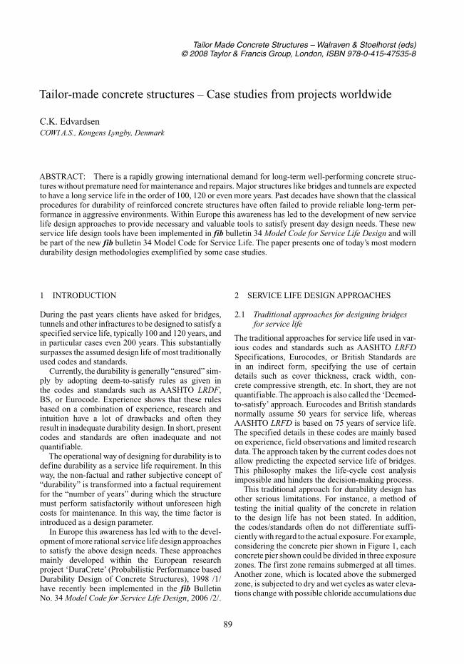
This traditional approach for durability design hasother serious limitations. For instance, a method oftesting the initial quality of the concrete in relationto the design life has not been stated. In addition,the codes/standards often do not differentiate suffi-ciently with regard to the actual exposure. For example,considering the concrete pier shown in Figure 1, eachconcrete pier shown could be divided in three exposurezones. The first zone remains submerged at all times.Another zone, which is located above the submergedzone, is subjected to dry and wet cycles as water eleva-tions change with possible chloride accumulations due
89
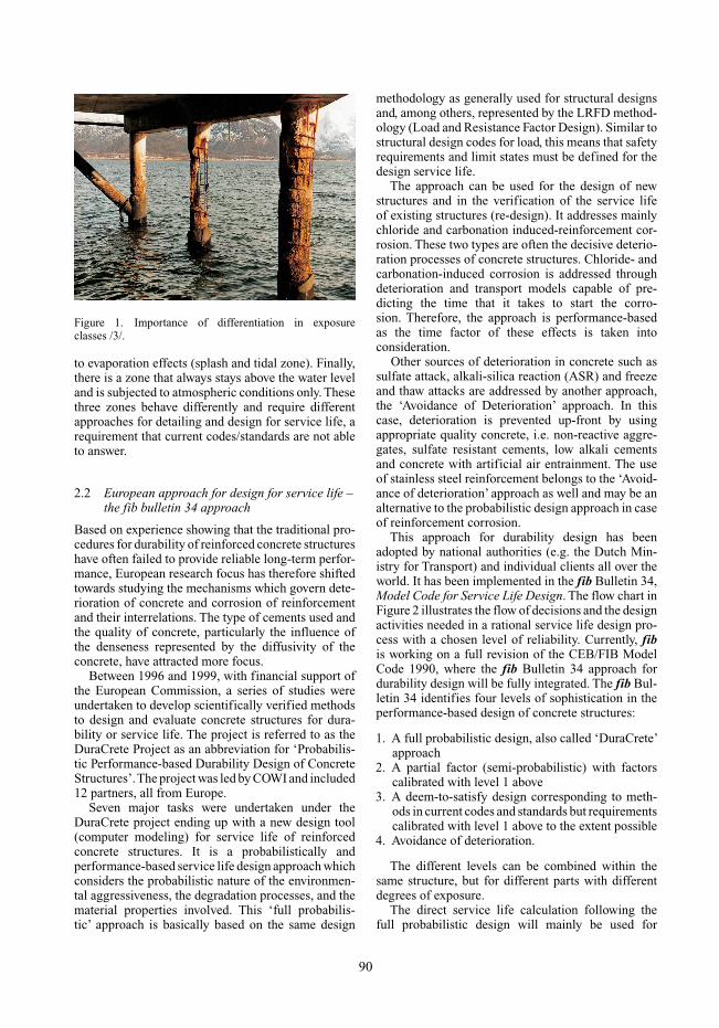
Figure 1. Importance of differentiation in exposureclasses /3/.
to evaporation effects (splash and tidal zone). Finally,there is a zone that always stays above the water leveland is subjected to atmospheric conditions only. Thesethree zones behave differently and require differentapproaches for detailing and design for service life, arequirement that current codes/standards are not ableto answer.
2.2 European approach for design for service life –the fib bulletin 34 approach
Based on experience showing that the traditional pro-cedures for durability of reinforced concrete structureshave often failed to provide reliable long-term perfor-mance, European research focus has therefore shiftedtowards studying the mechanisms which govern dete-rioration of concrete and corrosion of reinforcementand their interrelations. The type of cements used andthe quality of concrete, particularly the influence ofthe denseness represented by the diffusivity of theconcrete, have attracted more focus.
Between 1996 and 1999, with financial support ofthe European Commission, a series of studies wereundertaken to develop scientifically verified methodsto design and evaluate concrete structures for dura-bility or service life. The project is referred to as theDuraCrete Project as an abbreviation for ‘Probabilis-tic Performance-based Durability Design of ConcreteStructures’.The project was led by COWI and included12 partners, all from Europe.
Seven major tasks were undertaken under theDuraCrete project ending up with a new design tool(computer modeling) for service life of reinforcedconcrete structures. It is a probabilistically andperformance-based service life design approach whichconsiders the probabilistic nature of the environmen-tal aggressiveness, the degradation processes, and thematerial properties involved. This ‘full probabilis-tic’ approach is basically based on the same design
methodology as generally used for structural designsand, among others, represented by the LRFD method-ology (Load and Resistance Factor Design). Similar tostructural design codes for load, this means that safetyrequirements and limit states must be defined for thedesign service life.
The approach can be used for the design of newstructures and in the verification of the service lifeof existing structures (re-design). It addresses mainlychloride and carbonation induced-reinforcement cor-rosion. These two types are often the decisive deterio-ration processes of concrete structures. Chloride- andcarbonation-induced corrosion is addressed throughdeterioration and transport models capable of pre-dicting the time that it takes to start the corro-sion. Therefore, the approach is performance-basedas the time factor of these effects is taken intoconsideration.
Other sources of deterioration in concrete such assulfate attack, alkali-silica reaction (ASR) and freezeand thaw attacks are addressed by another approach,the ‘Avoidance of Deterioration’ approach. In thiscase, deterioration is prevented up-front by usingappropriate quality concrete, i.e. non-reactive aggre-gates, sulfate resistant cements, low alkali cementsand concrete with artificial air entrainment. The useof stainless steel reinforcement belongs to the ‘Avoid-ance of deterioration’ approach as well and may be analternative to the probabilistic design approach in caseof reinforcement corrosion.
This approach for durability design has beenadopted by national authorities (e.g. the Dutch Min-istry for Transport) and individual clients all over theworld. It has been implemented in the fib Bulletin 34,Model Code for Service Life Design. The flow chart inFigure 2 illustrates the flow of decisions and the designactivities needed in a rational service life design pro-cess with a chosen level of reliability. Currently, fibis working on a full revision of the CEB/FIB ModelCode 1990, where the fib Bulletin 34 approach fordurability design will be fully integrated. The fib Bul-letin 34 identifies four levels of sophistication in theperformance-based design of concrete structures:
1. A full probabilistic design, also called ‘DuraCrete’approach
2. A partial factor (semi-probabilistic) with factorscalibrated with level 1 above
3. A deem-to-satisfy design corresponding to meth-ods in current codes and standards but requirementscalibrated with level 1 above to the extent possible
4. Avoidance of deterioration.
The different levels can be combined within thesame structure, but for different parts with differentdegrees of exposure.
The direct service life calculation following thefull probabilistic design will mainly be used for
90
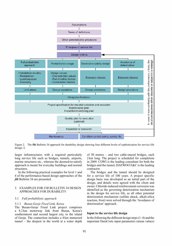
Figure 2. The fib Bulletin 34 approach for durability design showing four different levels of sophistication for service lifedesign /2.
larger infrastructures with a required particularlylong service life such as bridges, tunnels, airports,marine structures etc., whereas the deemed-to-satisfyapproach is meant for everyday buildings and normalstructures.
In the following practical examples for level 1 and4 of the performance-based design approaches of thefib Bulletin 34 are presented.
3 EXAMPLES FOR FIB BULLETIN 34 DESIGNAPPROACHES FOR DURABILITY
3.1 Full probabilistic approach
3.1.1 Busan-Geoje Fixed Link, KoreaThe Busan-Geoje Fixed Link project comprisesa 8.2 km motorway link from Busan, Korea’ssouthernmost and second largest city, to the islandof Geoje. The connection includes a 4 km immersedtunnel – the deepest in the world at a water depth
of 50 metres – and two cable-stayed bridges, each2 km long. The project is scheduled for completionin 2009. COWI is the leading consultant for both thebridges and the tunnel; DAEWOO E&C is the leadingcontractor.
The bridges and the tunnel should be designedfor a service life of 100 years. A project specificdesign basis was developed as an initial part of thedesign, and details were agreed with the client andowner. Chloride-induced reinforcement corrosion wasidentified as the governing deterioration mechanismin the design for service life, as all other potentialdeterioration mechanism (sulfate attack, alkali-silicareaction, frost) were solved through the ‘Avoidance ofdeterioration’ approach.
Input to the service life design
In the following the different design steps (1–4) and theimportant DuraCrete input parameters (mean values)
91
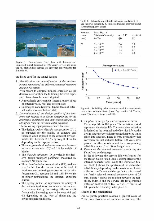
Figure 3. Busan-Geoje Fixed link with bridges andimmersed tunnel designed for 100 years’ service life usingthe full probabilistic service life approach following the fibBulletin 34.
are listed used for the tunnel design:
1. Identification and quantification of the environ-mental exposure of the different structural membersand their location.With regard to chloride-induced corrosion as thedecisive deterioration the following different expo-sure classes have been investigated:• Atmospheric environment (internal tunnel faces
of external walls, roof and bottom slab)• Submerged zone (external tunnel faces of exter-
nal walls, roof and bottom slab).2. Determination of the design quality of the con-
crete with respect to its design penetrability for theaggressive substances and their concentrations, asidentified from the environmental exposure.The following input parameters are decisive:• The design surface chloride concentration (Cl−s )
as expected for the quality of concrete andforeseen when exposed to the different environ-ments: Cl−s between 2–4 % by weight of binderdepending on the exposure class.
• The background chloride concentration foreseenin the concrete mix: Cl−0 = 0.1% by weight ofbinder.
• The chloride diffusivity (D−Cl) typically the deci-
sive design transport parameter measured bystandard NT Build 492.
• The critical chloride concentration (Cl−cr) is deci-sive for the chloride concentration at the level ofreinforcement, as it triggers corrosion on the rein-forcement: Cl−cr between 0.6 and 1.8% by weightof binder representing the different exposureclasses.
• The ageing factor (α) represents the ability ofthe concrete to develop an increased denseness.It is represented by decreasing diffusion coef-ficient with increasing age: α between 0.4 and0.6 depending on the type of binder and theenvironmental conditions.
Table 1. Interrelation chloride diffusion coefficient DCl−age factor α- reliability β. Immersed tunnel, internal tunnelfaces (atmospheric zone).
Nominal Max. DCl− atcover 28 days of maturity α = 0.40 α = 0.50(mm) (m2/s) (β) (β)
75 3 × 10⁻¹² 2.4 3.14 × 10⁻¹² 1.9 2.75 × 10⁻¹² 1.5 2.36 × 10⁻¹² 1.3 2.1
Atmospheric zone
0
1
2
3
4
5
0 20 40 60 80 100
Time [years]
Rel
iab
ility
ind
e
Dcl� = 6.0�10�12 m2/s
Figure 4. Reliability index versus service life – atmosphericzone – internal tunnel faces (max. DCl− = 6.0 × 10⁻¹² m2/s,cover: 75 mm, age factor α = 0.40).
3. Adoption of design life and acceptance criteria.The design life is 100 years. The initiation periodrepresents the design life. Thus corrosion initiationis defined as the nominal end of service life. At thedesign stage the corrosion propagation period is nottaken into account. There is 90% probability thatcorrosion has not initiated before 100 years havepassed. In other words, adopt the correspondingreliability index (β = 1.3) as design basis.
4. Determine the nominal concrete cover using theDuraCrete methodology.In the following the service life verification forthe Busan-Geoje Fixed Link is exemplified for theinternal concrete faces inside the immersed tun-nel. Table 1 shows the spectrum of the obtainablereliabilities β depending on the maximum chloridediffusion coefficient and the age factor α in case ofthe finally selected nominal concrete cover of 75mm. Figure 4 shows the relation between the reli-ability index β and the service life for a chloridediffusion coefficient of DCl− = 6 × 10⁻¹² m2/s. At100 years the reliability index β = 1.3.
Results of the calculations
Due to purely practical reasons a general cover of75 mm was chosen on all surfaces in this case. The
92
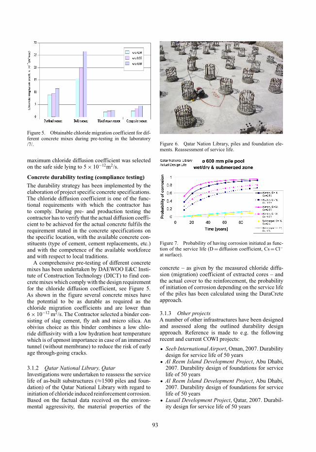
Figure 5. Obtainable chloride migration coefficient for dif-ferent concrete mixes during pre-testing in the laboratory/7/.
maximum chloride diffusion coefficient was selectedon the safe side lying to 5 × 10⁻¹²m2/s.
Concrete durability testing (compliance testing)
The durability strategy has been implemented by theelaboration of project specific concrete specifications.The chloride diffusion coefficient is one of the func-tional requirements with which the contractor hasto comply. During pre- and production testing thecontractor has to verify that the actual diffusion coeffi-cient to be achieved for the actual concrete fulfils therequirement stated in the concrete specifications onthe specific location, with the available concrete con-stituents (type of cement, cement replacements, etc.)and with the competence of the available workforceand with respect to local traditions.
A comprehensive pre-testing of different concretemixes has been undertaken by DAEWOO E&C Insti-tute of Construction Technology (DICT) to find con-crete mixes which comply with the design requirementfor the chloride diffusion coefficient, see Figure 5.As shown in the figure several concrete mixes havethe potential to be as durable as required as thechloride migration coefficients and are lower than6 × 10−12 m2/s. The Contractor selected a binder con-sisting of slag cement, fly ash and micro silica. Anobivius choice as this binder combines a low chlo-ride diffusivity with a low hydration heat temperaturewhich is of upmost importance in case of an immersedtunnel (without membrane) to reduce the risk of earlyage through-going cracks.
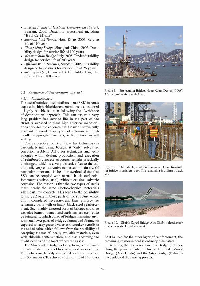
3.1.2 Qatar National Library, QatarInvestigations were undertaken to reassess the servicelife of as-built substructures (≈1500 piles and foun-dation) of the Qatar National Library with regard toinitiation of chloride induced reinforcement corrosion.Based on the factual data received on the environ-mental aggressivity, the material properties of the
Figure 6. Qatar Nation Library, piles and foundation ele-ments. Reassessment of service life.
Figure 7. Probability of having corrosion initiated as func-tion of the service life (D = diffusion coefficient, Cs = Cl−at surface).
concrete – as given by the measured chloride diffu-sion (migration) coefficient of extracted cores – andthe actual cover to the reinforcement, the probabilityof initiation of corrosion depending on the service lifeof the piles has been calculated using the DuraCreteapproach.
3.1.3 Other projectsA number of other infrastructures have been designedand assessed along the outlined durability designapproach. Reference is made to e.g. the followingrecent and current COWI projects:
• Seeb International Airport, Oman, 2007. Durabilitydesign for service life of 50 years
• Al Reem Island Development Project, Abu Dhabi,2007. Durability design of foundations for servicelife of 50 years
• Al Reem Island Development Project, Abu Dhabi,2007. Durability design of foundations for servicelife of 50 years
• Lusail Development Project, Qatar, 2007. Durabil-ity design for service life of 50 years
93
• Bahrain Financial Harbour Development Project,Bahrain, 2006. Durability assessment including“Birth Certificate”
• Shannon Link Tunnel, Hong Kong, 2005. Servicelife of 100 years
• Chong Ming Bridge, Shanghai, China, 2005. Dura-bility design for service life of 100 years
• Messina Strait Bridge, Italy, 2005. Tender durabilitydesign for service life of 200 years
• Offshore Wind Turbines, Sweden, 2005. Durabilitydesign of foundations for service life of 25 years
• SuTong Bridge, China, 2003. Durability design forservice life of 100 years
3.2 Avoidance of deterioration approach
3.2.1 Stainless steelThe use of stainless steel reinforcement (SSR) in zonesexposed to high chloride concentrations is considereda highly reliable solution following the ‘Avoidanceof deterioration’ approach. This can ensure a verylong problem-free service life in the part of thestructure exposed to these high chloride concentra-tions provided the concrete itself is made sufficientlyresistant to avoid other types of deterioration suchas alkali-aggregate reactions, sulfate attack, or saltscaling.
From a practical point of view this technology isparticularly interesting because it “only” solves thecorrosion problem. All other techniques and tech-nologies within design, production, and executionof reinforced concrete structures remain practicallyunchanged, which is a very attractive fact to the tra-ditionally very conservative construction industry. Ofparticular importance is the often overlooked fact thatSSR can be coupled with normal black steel rein-forcement (carbon steel) without causing galvaniccorrosion. The reason is that the two types of steelsreach nearly the same electro-chemical potentialswhen cast into concrete. This leads to the possibilityto use SSR only in those parts of the structure wherethis is considered necessary, and then reinforce theremaining parts with ordinary black steel reinforce-ment. Such highly exposed parts of bridges could bee.g. edge beams, parapets and crash barriers exposed tode-icing salts, splash zones of bridges in marine envi-ronment, lower parts of bridge columns and abutmentsexposed to salty groundwater etc. Another benefit isthe added value which follows from the possibility ofaccepting the use of locally available materials, evenwith chloride contamination, and also accepting thequalifications of the local workforce as it is.
The Stonecutter Bridge in Hong Kong is one exam-ple where stainless steel has been used successfully.The pylons are heavily reinforced with a multi-layerof ø 50 mm bars. To achieve a service life of 100 years
Figure 8. Stonecuttter Bridge, Hong Kong. Design: COWIA/S in joint venture with Arup.
Figure 9. The outer layer of reinforcement of the Stonecutt-ter Bridge is stainless steel. The remaining is ordinary blacksteel.
Figure 10. Sheikh Zayed Bridge, Abu Dhabi, selective useof stainless steel reinforcement.
SSR is used for the outer layer of reinforcement, theremaining reinforcement is ordinary black steel.
Similarly, the Shenzhen Corridor Bridge (betweenHong Kong and mainland China), the Sheikh ZayedBridge (Abu Dhabi) and the Sitra Bridge (Bahrain)have adopted the same approach.
94
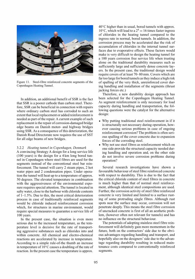
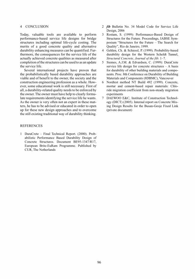
Figure 11. Steel-fibre reinforced concrete segments of theCopenhagen Heating Tunnel.
In addition, an additional benefit of SSR is the factthat SSR is a poorer cathode than carbon steel. There-fore, SSR can be beneficial in connection with repairswhere ordinary carbon steel has corroded to such anextent that local replacement or added reinforcement isneeded as part of the repair. A current example of suchreplacement is the repair of corrosion-damaged bridgeedge beams on Danish motor- and highway bridgesusing SSR. As a consequence of this deterioration, theDanish Road Directorate now requires the use of SSTfor all edge beams of new bridges.
3.2.2 Heating tunnel in Copenhagen, DenmarkA convincing Strategy A design for a long service life(100 years) is the design for a 4 km long bored tun-nel in Copenhagen where steel fibres are used for thesegments instead of the conventional steel bar rein-forcement. The tunnel will carry 2 steam pipes, 2 hotwater pipes and 2 condensation pipes. Under opera-tion the tunnel will heat up to a temperature of approx.50 degrees. The elevated temperature in combinationwith the aggressiveness of the environmental expo-sure requires special attention. The tunnel is located insalty water, close to the harbour with chloride contentsof 1–1.5%. Due to this, the most critical deteriorationprocess in case of traditionally reinforced segmentswould be chloride induced reinforcement corrosionwhich, for structures in marine environment, wouldrequire special measures to guarantee a service life of100 years.
In the present case, the situation is even moreserious due to the increased temperature, as the tem-perature level is decisive for the rate of transport-ing aggressive substances such as chlorides into andwithin concrete. All chemical and electro-chemicalreactions are accelerated by increase in temperature.According to a simple rule-of-the thumb an increasein temperature of 10◦C causes a doubling of the rate ofreaction. In the present case the temperature is approx.
40◦C higher than in usual, bored tunnels with approx.10◦C, which will lead to a 24 = 16 times faster ingressof chlorides in the heating tunnel compared to theingress rate in normal, bored tunnels. In addition, thecorrosion process may be accelerated due the risk ofaccumulation of chlorides in the internal tunnel sur-faces due to evaporative effects. These factors wouldmake is very difficult to design the heating tunnel fora 100 years corrosion free service life when trustingalone on the traditional durability measures such assufficiently large and sufficiently dense concrete lay-ers. In the present case, the traditional design wouldrequire covers of at least 70–80 mm. Covers which arefar too large for bored tunnels as they induce a high riskof spalling of the very thick, unreinforced cover dur-ing handling and installation of the segments (thrustjacking forces etc.)
Therefore, a new durability design approach hasbeen selected for the Copenhagen Heating Tunnel.As segment reinforcement is only necessary for loadcapacity during handling and transportation, the fol-lowing questions were the catalyst for the alternativedesign:
• Why putting traditional steel reinforcement in if itis structurally not necessary during operation, how-ever causing serious problems in case of ongoingreinforcement corrosion? The problem is often seri-ous spalling of the cover concrete due to expansionforces of the corroding steel.
• Why not use steel fibres as reinforcement which onone side provide the structural capacity needed dur-ing handling and operation and, on the other sidedo not involve severe corrosion problems duringoperation?
Several research investigations have shown afavourable behaviour of steel fibre reinforced concretewith respect to durability. This is due to the fact thatthe critical chloride content of steel fibres in concreteis much higher than that of normal steel reinforce-ment, although identical steel compositions are used.Further, the corrosion activity of steel fibre reinforcedconcrete is very limited and limited to a surface rust-ing of some protruding single fibres. Although rustspots near the surface may occur, corrosion will notpenetrate deeply. This means the steel fibre corrosionof uncracked concrete is first of all an aesthetic prob-lem, (however often not relevant for tunnels) and hasno influence on the structural behaviour.
The potentials of adopting stainless steel fibre rein-forcement will definitely gain more momentum in thefuture, both on the contractors’ side due to the obvi-ous advantages regarding handling and transport, andhopefully also on the designers’ side due to the advan-tage regarding durability resulting in reduced main-tenance costs compared to conventionally reinforcedsegments.
95
4 CONCLUSION
Today, valuable tools are available to performperformance-based service life designs for bridgestructures including optimal life-cycle costing. Themerits of a good concrete quality and alternativedurability enhancing measures can be quantified. Fur-thermore, the consequences for the service life of theactually achieved concrete qualities as measured aftercompletion of the structures can be used to as an updatethe service life.
Several international projects have proven thatthe probabilistically based durability approaches areviable and of benefit to the owner, the society and theconstruction engineering profession as a whole. How-ever, some educational work is still necessary. First ofall, a durability-related quality needs to be enforced bythe owner. The owner must have help to clearly formu-late requirements identifying the service life he wants.As the owner is very often not an expert in these mat-ters, he has to be advised or educated in order to openup for these new design approaches and to overcomethe still existing traditional way of durability thinking.
REFERENCES
1 DuraCrete – Final Technical Report. (2000). Prob-abilistic Performance Based Durability Design ofConcrete Structures. Document BE95-1347/R17,European Brite-EuRam Programme. Published byCUR, The Netherlands
2 fib Bulletin No. 34 Model Code for Service LifeDesign, 2006
3 Rostam, S. (1999): Performance-Based Design ofStructures for the Future. Proceedings, IABSE Sym-posium “Structures for the Future – The Search forQuality”, Rio de Janeiro, 1999.
4 Gehlen, Ch. & Schiessl, P. (1999). Probability-baseddurability design for the Western Scheldt Tunnel,Structural Concrete, Journal of the fib: 1–7.
5 Siemes, A.J.M. & Edvardsen, C. (1999): DuraCreteservice life design for concrete structures – A basisfor durability of other building materials and compo-nents. Proc. 8th Conference on Durability of BuildingMaterials and Components (8DBMC), Vancouver
6 Nordtest method NT Build 492 (1999). Concrete,mortar and cement-based repair materials: Chlo-ride migration coefficient from non-steady migrationexperiments
7 DAEWOO E&C, Institute of Construction Technol-ogy (DICT) (2005). Internal report on Concrete Mix-ing Design Results for the Busan-Geoje Fixed Link(private document)
96