Tailgate, (wagon)
14
55-30 Tailgate, (wagon) Assembly overview Repair Manual, Body Collision Repair,Repair Group 00; Body gaps/shut lines; Body rear Repair Manual, Body Interior, Repair Group 70; Removing and installing tailgate trim 1 - Tailgate/tailgate Adjusting Page 55 - 15 Gaps/shut lines To remove, it is only necessary to remove hexagon nut - 10 - 2 - Trim - Remove tailgate trim. 3 - Clip 4 - Adjustment buffer Adjusting Page 55 - 15 Same as saloon 5 - Ball pin 21 Nm
Transcript of Tailgate, (wagon)
55-30
Tailgate, (wagon) Assembly overview
Repair Manual, Body Collision Repair,Repair Group 00; Body gaps/shut lines; Body rear
Repair Manual, Body Interior, Repair Group 70; Removing and installing tailgate trim
1 - Tailgate/tailgate
Adjusting Page 55-15
Gaps/shut lines
To remove, it is only necessary to remove hexagon nut - 10 -
2 - Trim
- Remove tailgate trim.
3 - Clip
4 - Adjustment buffer
Adjusting Page 55-15
Same as saloon
5 - Ball pin
21 Nm
55-31
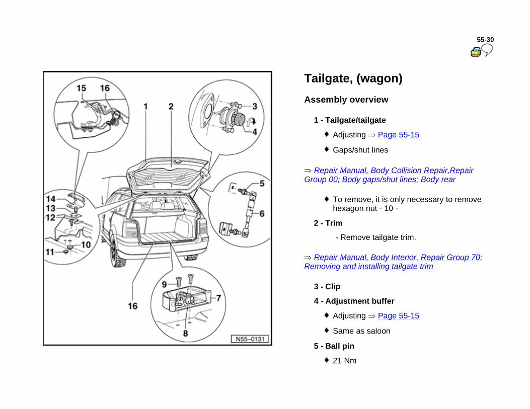
Repair Manual, Body Collision Repair,Repair Group 00; Body gaps/shut lines; Body rear
6 - Gas-filled strut
Removing and installing Page 55-13
Releasing gas Page 55-14
7 - Lock plate cover
8 - Lock plate
Adjusting - within oversized holes
Gaps/shut lines
9 - Bolt
23 Nm
10 - Hexagon nut
22 Nm
Tailgate can be removed by unscrewing this hexagon nut

55-32
11 - Hexagon nut
10 Nm
12 - Adapter plate
With the adapter plate the tailgate adjustment is discontinued
13 - Seal
14 - Hinge
15 - 12 point head bolt
10 Nm
16 - Seal

55-33
Tailgate lock, removing and installing up to 10.00
1 - Lock cylinder carrier
The lock cylinder can only be removed in conjunction with the carrier.
Removing and installing Page 55-27 .
2 - Hexagon nut
7 Nm
3 - Handle trim
Removing
- Remove lock cylinder carrier Page 55-27 .
- Separate connector for number plate light.
- Unscrew hexagon nuts - 2 - and take outer hand grip off tailgate.
4 - Handle
5 - Push-button

55-34
Repair Manual, Body Interior, Repair Group 70; Removing and installing tailgate trim
6 - Pop rivet nut
Pull in with pop rivet nut tool V.A.G 1765 B
7 - Base for registration plate
Only press on the hatched area
The replacement part has two foils. The first foil covers the adhesive surface, the second must be pulled off after assembling.
8 - Operating rod
9 - Lock
Removing
- Remove tailgate trim.
- Disconnect connector on lock.
- Unclip operating rod - 8 -, remove bolt - 10 - and take lock off tailgate.
55-35
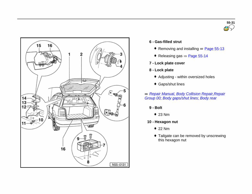
10 - Bolt
23 Nm
11 - Central locking actuator
Removing
- Remove lock cylinder carrier Page 55-27 .
- Unbolt actuator and allow to hang.
12 - Tailgate release motor (V139)
Only USA
13 - Hexagon nut
7 Nm
14 - Relay lever

55-36
Lock cylinder carrier, removing and installing up to 10.00
Removing
- Remove tailgate trim
Repair Manual, Body Interior, Repair Group 70; Removing and installing tailgate trim
- Separate connectors -arrows-.
- Unclip operating rod -2- for tailgate lock.
- Unscrew hexagon nuts -1-.
55-37
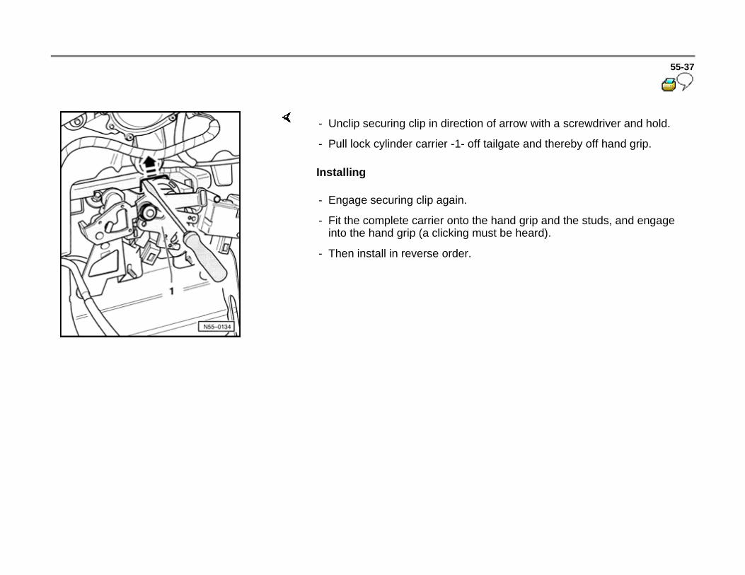
Installing
- Unclip securing clip in direction of arrow with a screwdriver and hold.
- Pull lock cylinder carrier -1- off tailgate and thereby off hand grip.
- Engage securing clip again.
- Fit the complete carrier onto the hand grip and the studs, and engage into the hand grip (a clicking must be heard).
- Then install in reverse order.

55-38
Tailgate lock and lock cylinder carrier, removing and installing from 10.00
Removing
Installing
1 - Carrier lock cylinder
- Disconnect harness connectors for
license plate light, power lock adjusting motor and lock cylinder switch.
- Unclip bowden cable -4- at lock. Then remove hex nut -8-.
- Carrier lock cylinder can now be removed from tailgate.
Installation is the reverse order of removal.
2 - Motor to unlock -V139-
55-39
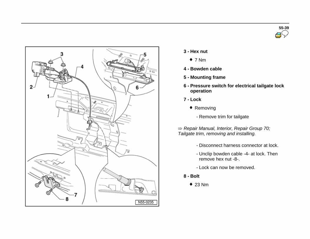
Repair Manual, Interior, Repair Group 70; Tailgate trim, removing and installing.
3 - Hex nut
7 Nm
4 - Bowden cable
5 - Mounting frame
6 - Pressure switch for electrical tailgate lock operation
7 - Lock
Removing
- Remove trim for tailgate
- Disconnect harness connector at lock.
- Unclip bowden cable -4- at lock. Then remove hex nut -8-.
- Lock can now be removed.
8 - Bolt
23 Nm
55-40
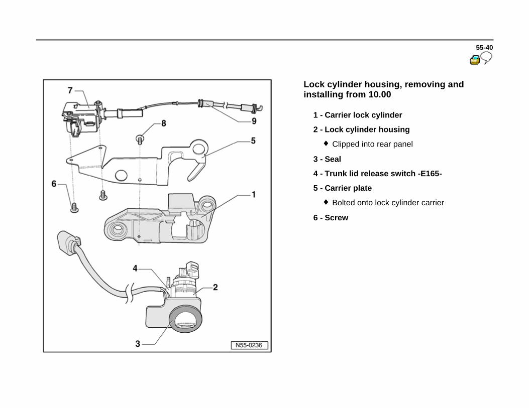
Lock cylinder housing, removing and installing from 10.00
1 - Carrier lock cylinder
2 - Lock cylinder housing
Clipped into rear panel
3 - Seal
4 - Trunk lid release switch -E165-
5 - Carrier plate
Bolted onto lock cylinder carrier
6 - Screw

55-41
7 - Motor to unlock rear lid -V139-
Removing
- Removing lock cylinder carrier -1- Page 55-24 .
- Unbolt motor and unhook.
8 - Screw
9 - Bowden cable
55-42
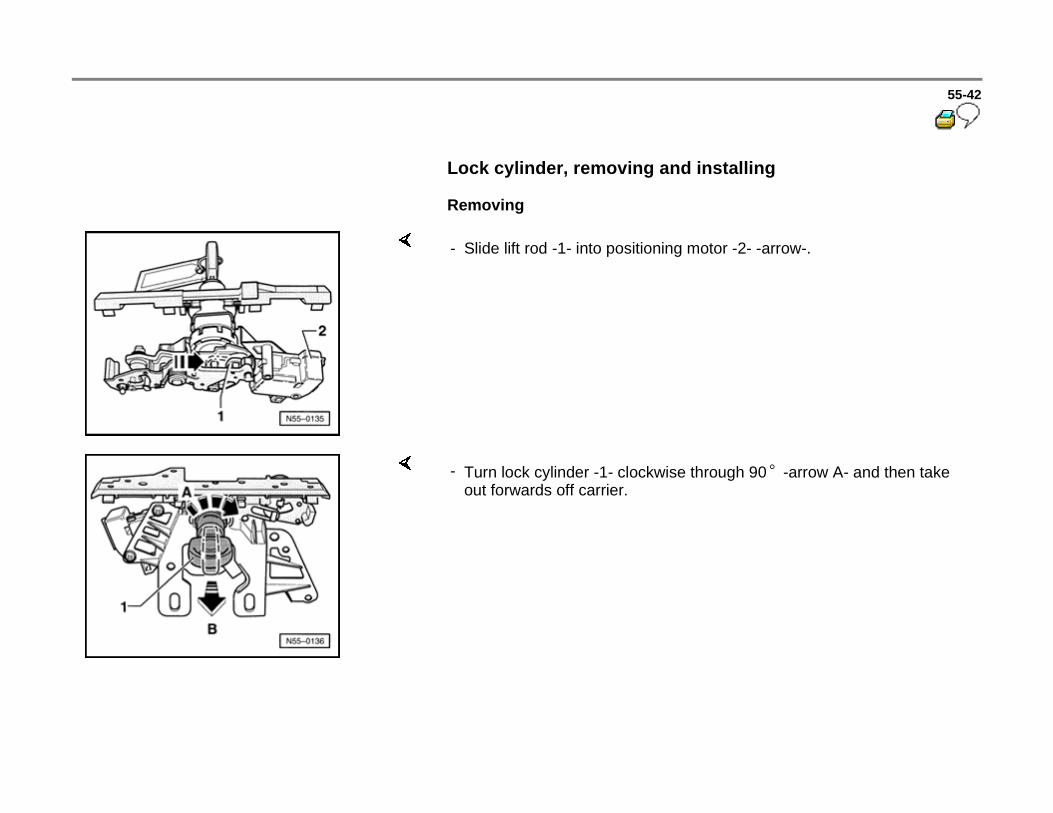
Lock cylinder, removing and installing
Removing
- Slide lift rod -1- into positioning motor -2- -arrow-.
- Turn lock cylinder -1- clockwise through 90 -arrow A- and then take out forwards off carrier.

55-43
Installing
- Insert lock cylinder in carrier -1- -arrow A-, turn anti-clockwise through 90 -arrow B-.
- Lift rod -1- must be pulled out of positioning motor -2- in this position. Simultaneously the lock cylinder is engaged in the carrier with an audible check.