
TAIG TOOLS - DesktopLathes · PDF fileCongratulations on your purchase of the Micro Lathe II....
17
Congratulations on your purchase of the Micro Lathe II. It should provide years of service with little maintenance. Y'our lathe is covered by a 2 year labor and material unconditional fact9ry warranty- HAPPY MACHININGI! CAPACITY L 1017 Swing bed 4 1/2" (Max. turning dia. 4 1/2") Swing over cross fide 2 3/S" dia. Overall length of bed 15 1/2" Overall length of lathe 16 1/2" . Tool bit size std. 1/4" Distance between centers 9 3/4" (tailstock optional) Carriage traver 9" Crosslide travel 1 3/4" MICRO LATHE NOTES SPINDLE Sealed precision ball 1.5748 0.0.,6692 1.0. Spindle nose 3/4" .. 16 (3/4" SAE) Spindle hole .343 Spindle 1.0. taper 15 degrees (30 degrees included) Max. collet dia. 9/32" Pulley size 5/8" bore TAIG TOOLS 12419 E. NIGHTINGALE LANE CHANDLER, AZ 85286-2218 PHONE: 480-895-6978 FAX: 480-8900.9648
Transcript of TAIG TOOLS - DesktopLathes · PDF fileCongratulations on your purchase of the Micro Lathe II....

Congratulations on your purchaseof the Micro Lathe II. It shouldprovide years of service with littlemaintenance. Y'our lathe is coveredby a 2 year labor and materialunconditional fact9ry warranty-
HAPPY MACHININGI!
CAPACITY L 1017
Swing ov~r bed 4 1/2" (Max. turning dia. 4 1/2")Swing over crossfide 2 3/S" dia.Overall length of bed 15 1/2"Overall length of lathe 16 1/2" .Tool bit size std. 1/4"Distance between centers 9 3/4" (tailstock optional)Carriage traver 9"Crosslide travel 1 3/4"
MICRO LATHE NOTES
SPINDLE
Sealed precision ball 1.5748 0.0.,6692 1.0.Spindle nose 3/4"..16 (3/4" SAE)Spindle hole .343Spindle 1.0. taper 15 degrees (30 degrees included)Max. collet dia. 9/32"Pulley size 5/8" bore
TAIG TOOLS12419 E. NIGHTINGALE LANECHANDLER, AZ 85286-2218
PHONE: 480-895-6978FAX: 480-8900.9648

Your Lathe
tCarriage"Handwheel
GibLock Carriage
~ assemblyGib
Adjust~
HeadstockSpindle
~;.
Headstock Tool Post / ......~f ...........--.......!i-----.......assembly ;t
Crosslide ICarriage
Depth Stop Crosslide Dial
~~i~::'~~?:F~:Y~;:~lt~~~~::,;?;-:!;~::""::",I------.. -.~ ;.' '."~-.":: .~::.~): ~_., ' .:: / 1--....
Rotation
CAUTION:
- Always use SAFETY GLASSES to protect eyes from chips.- Tighten chucks securely to avoid unscrewing during operation.- DO NOT slow lathe with hand on pulley.- Operate chucks in excess of middle speed with care.- DO NOT have the belt tight as this causes the spindle to
stop quickly and may cause the chuck to unscrew.
CAUTIONII
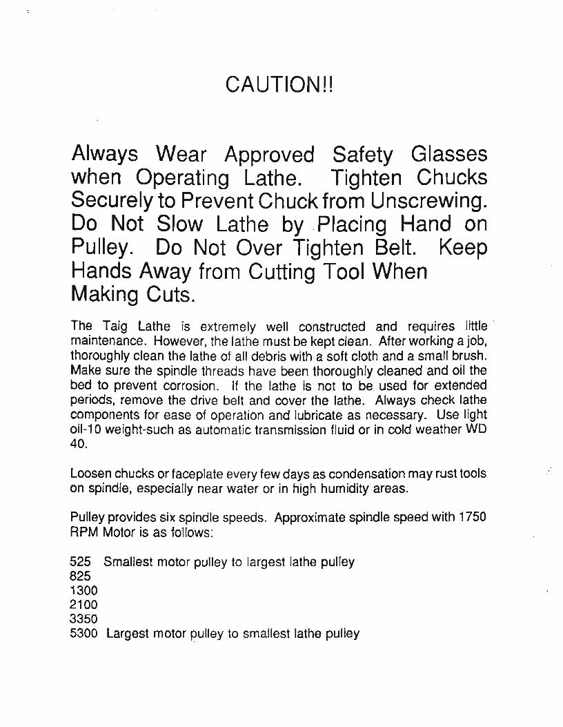
Always Wear Approved Safety Glasseswhen Operating Lathe. Tighten ChucksSecurely to Prevent Chuck from Unscrewing.Do Not Slow Lathe by. Placing Hand onPulley. Do Not Over Tighten Belt. KeepHands Away from Cutting Tool WhenMaking Cuts.
The Taig Lathe is extremely well constructed and requires little'maintenance. However, the lathe must be kept clean. After working a job,thoroughly clean the lathe of all debris with a soft cloth and a small brush.Make sure the spindle threads have been thoroughly cleaned and oil thebed to prevent corrosion. If the lathe is not to be used for extendedperiods, remove the drive belt and cover the lathe. Always check lathecomponents for ease of operation and lubricate as necessary. Use lightoil-10 weight-such as automatic transmission fluid or in cold weather WD40.
Loosen chucks or faceplate every few days as condensation may rust toolson spindle, especially near water or in high humidity areas.
Pulley provides six spindle speeds. Approximate spindle speed with 1750RPM Motor is as follows:
525 Smallest motor pulley to largest lathe pulley8251300210033505300 largest motor pulley to smallest lathe pulley

The motor should sit on an anglewith the weight of the motor onthe belt. The motor bracket shouldbe loose on the board to allowthe motor to be raised in orderto change speeds. Make sure thebelt contacts properly.
\A!j:\sll t R 1~r.1~:=hd~=~
rMG8N1'ING-BOARb'~'~: ,-,,,-., ,',::': ,-,.: .. , ,',:: \-1~ " ~ " > '-;1 ;:;; .-. ') . " )... , ,)... , J
gears are off-center to shaftpart #100·13
RACK
Rotate the eccentricto engage the gear onthe rack. Install"E" clip on the gearto hold it in place.
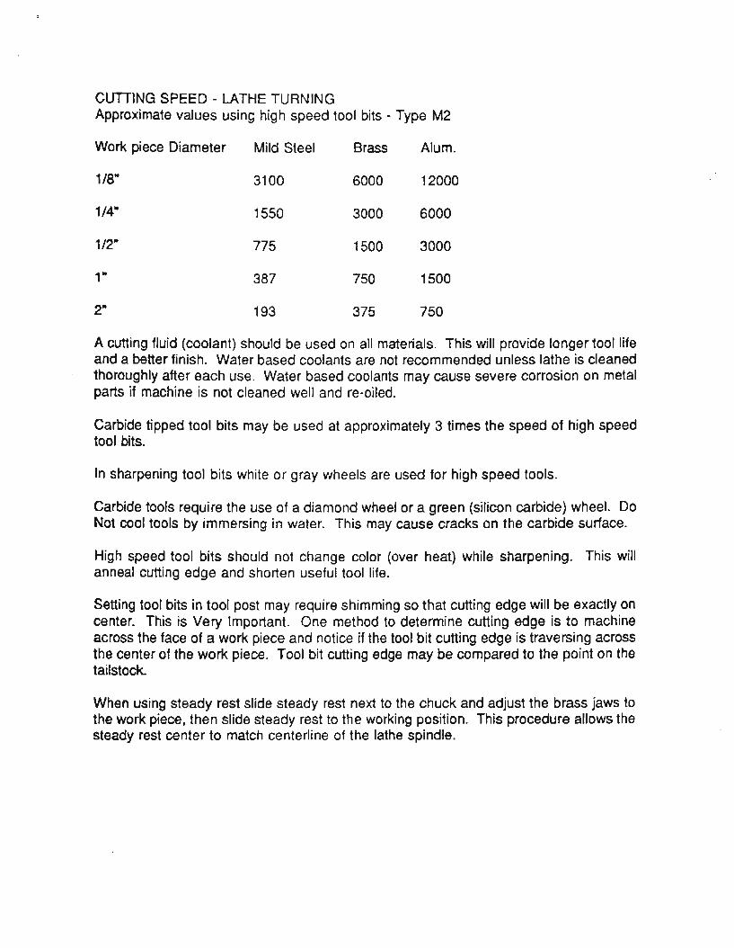
CUTIING SPEED - LATHE TURNINGApproximate values using high speed tool bits - Type M2
Work piece Diameter Mild Steel Brass Alum.
1/8" 3100 6000 12000
1/4" 1550 3000 6000
1/2" 775 1500 3000
1" 387 750 1500
2" 193 375 750
A cutting fluid (coolant) should be used on all materials. This will provide longer tool lifeand a better finish. Water based coolants are not recommended unless lathe is cleanedthoroughly after each use. Water based coolants may cause severe corrosion on metalparts if machine is not cleaned well and re-oiled.
Carbide tipped tool bits may be used at approximately 3 times the speed of high speedtool bits.
In sharpening tool bits white or gray wheels are used for high speed tools.
Carbide tools require the use of a diamond wheel or a green (silicon carbide) wheel. DoNot cool tools by immersing in water. This may cause cracks on the carbide surface.
High speed tool bits should not change color (over heat) while sharpening. This willanneal cutting edge and shorten useful tool life.
Setting tool bits in tool post may require shimming so that cutting edge will be exactly oncenter. This is Very Important. One method to determine cutting edge is to machineacross the face of a work piece and notice if the tool bit cutting edge is traversing acrossthe center of the work piece. Tool bit cutting edge may be compared to the point on thetailstock.
When using steady rest slide steady rest next to the chuck and adjust the brass jaws tothe work piece, then slide steady rest to the working position. This procedure allows thesteady rest center to match centerline of the lathe spindle.

MicroLathe
Headsock
PART #1026 DEPTH STOP
JTIIf «1J~l.6-1 ---.-..ft....ulICJilrnB
LatheChuck
DelJlll SlopIIlstal Ied ill
SpiJldle
• Used to provide stop for workpiece held in chuck
• Parts held in chuck Inay be I11achined to saine length
• Jaws are independently adjustedin pairs. Four-jaw chucks are by fartile ITIOst vesatile of all Cllucks
• Parts Inay be machined to run verytrue. This will require more time tocenter than a three-jaw. Setting aworkpiece off-center creates crankshaft and cam shapes
AdjustIn paIrs
PART #1030 FOUR-JAW CHUCK• Hardened steel with stepsReversible range 1/8 - 3 1/4 ins.

Your options for workpiece mounting hardware are as fonows:
Part 1030: 4 Jaw Oluck
Part 1050: 3 Jaw Chuck -----....

PART #1035·. FACE PLATES
Stop
• Faceplates are used to run shaftsbetween centers and to fixture spe-cial jobs
• Holes can be drilled and tapped i1needed in faceplate
Faceplate
\Vorkpiece
SpecialStops
Use of Clarnps
Faceplate
AngleBracket
PART #1036 1 X 1 IN. SQUAREANGLE BRACKETS (2 PIECES)

·.,.
...
'Part 1035: Faceplate'Part 1036: Anv).e Bl'ackets----r

·PART #1040PARTffl042
COLLETCLOSER
Collet is used fOl· sInaI J
dialnetel· sllaft \vork alldholding cutters for nlilJing.Sizes are 1/8, 5/32, 3/16, 7/32,1/4 &.9/32 iIlclles -- 5/16 illCll
is a stub c.ollet of 3"/8 illclles ill
depth.
• Advantages of collets are they are fast and accurate and spindlenlay be run at InaxinlUll1 speed on altllninUITI and brass.
• Collets will accept material that is .001 over collet size to .004under collet size. Bar stock is nonnaJly within this tolerance.
Blanl{ Collet #1043
Center Mark
• Used to modifystaIldal·d screws
• Ivtay be used to l1lake special sizes
Drill and tap so screwwill protrude
Macllille llead to suit

~,arbornut---
Part 1052: Full Circle Jaw
Part 1040: ColletPart 1042: Collet Coser NutPart 1026: Depth StopPart 1043: Blank Collet collet (slotted, drilled and threaded)
depth stop (drilled and threaded)blank collet (solid-not ~hined)
collet closer nut
.~~~/

PART #1050 THREE-JAW CHUCI( ·
To achieve best accuracysoft jaws lTIllSt be trued onspindle chuck will be used
011
• Part #1050 is 3 1/4 inches indialnetel·
• All steel scroll chuck withalulninun top jaws (commonlycalled soft jaws)• Three jaw chucks are used tohold round and hex material.• The self centering abilityenables all three jaws to move attIle same ti me.
Belt
~~-
Rotate ring to Inove jaws
Close jaws on washer
Washer
o
Set depth Stoprod to prevent tool bit frOll1 washer
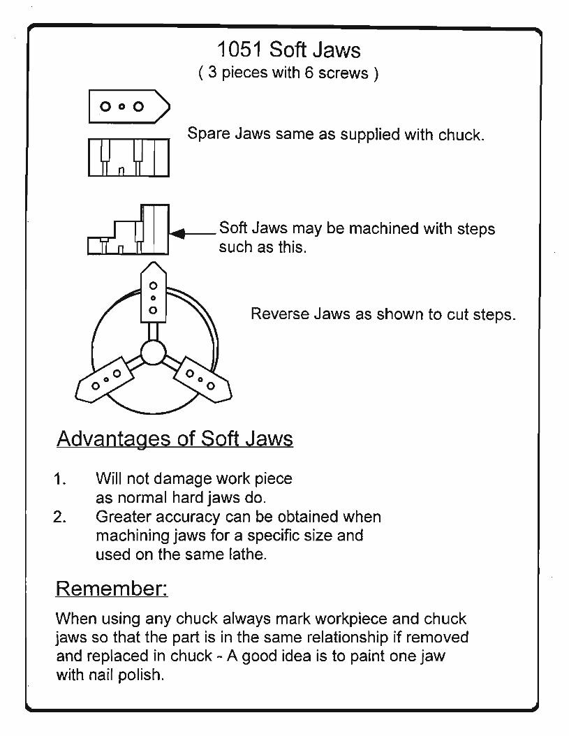
1051 Soft Jaws( 3 pieces with 6 screws)
1000)
Spare Jaws same as supplied with chuck.
~_Soft Jaws may be machined with stepssuch as this.
Reverse Jaws as shown to cut steps.
Advantages of Soft Jaws
10 Will not damage work pieceas normal hard jaws do.
2. Greater accuracy can be obtained whenmachining jaws for a specific size andused on the same lathe.
Remember:When using any chuck always mark workpiece and chuckjaws so that the part is in the same relationship if removedand replaced in chuck - A good idea is to paint one jawwith nail polish.

PART #1052 FULL CIRCLE J~W. "
\ @'1
Sho\vn \vith steps
• To bore jaws, place 1/4 inchdiameter pin in center
• Jaws may be cut with steps tohold thin disks or clock gears
• Thin wall tubes that regular threejaws would damage may be held bymachining jaws to exact size oftube so that almost 100% contacton tube will be achieved

Part 1200: Top Slide (Compound)
A compound is used for angles and short tapers on the work piece. Thepositive length may be achieved by having the compound 90 degrees tothe crosslide and by using the dial on the compound to control the lengthof the cut.
The compound will attach to either "tee" slot of the crosslide and will rotateand be clamped at any angle. The tool bit is clamped directly on the tableof the compound.

PART #1152. DIE HOLDER
• Threads Inay be put on a part \vith a button-die. This is a roundpiece of tooled steel with thread-cutting grooves. The dialnetersof small button-dies are 13/16 and 1.00 inches. In this size,
threads may be cut from 0-80 to 1/2 inch.Die The purpose of a die holder is to align
alld allow the button-die to cut a tl·ue anduntapered thread.. When scre\ving thebutton die on workpiece, always have a
45 degree chalnfer (edge brake) on end of shaft to be threaded.
Die I-Iolder
..---SlideButton-Die
WORKPlECE I··{ELD ONCENTER BY t-IEA DS Toe 1\CHUCK OR COLLET

Part 1220: Milling i\ttachment Approximate cutting speed usinghigh speed end mills in RPM.
Alum. Brass Steel3/16 dia. 2100 1300 5251/8.dia. 3350 2100 8251/16 dia. 5300 5300 2100longer tool life and betterfinishes may. be obtained usinga cutting fluid. For steel apipe thread cutting oil worksvery wen. For alum. or brasskerosene or diesel fuel may beused.
The·l220 Milling Attachment provides vertical travel of approx. 1 3/4 inches. The crosslide dial provides travelin·.001 increments direct reading.The cutters (end mills) are held in the spindle with the collets to provide maximum ridgidty. Miniature end millsc~me with 3/16 dia. bodies and various size cutting diameters. The end mills will cut all materials steel, alum. t
brass and plastics.
o 0
ooCarbide tipped router bitswith 1/4 inch diameter bodymay be used ·for cutting alum.•brass, plastics and wood. Theyare not recommended for steel.Carbide tools should run at least4 times faster than high speedend mills of comparable size.