Tactical High Frequency Communications in the … in its scope is investigation of possible future...
54
("DEPARTMENT OF DEFENCT DEFENCE SCIENCE & TECHNOLOGY ORGANISATION DSTO Tactical High Frequency Communications in the Land Arena - The Current State of the Art A.B. Reynolds and W.D. Blair DSTO-CR-0214 DISTRIBUTION STATEMENT A Approved for Public Release •. Distribution Unlimited 20020108 116
Transcript of Tactical High Frequency Communications in the … in its scope is investigation of possible future...

("DEPARTMENT OF DEFENCT
DEFENCE SCIENCE & TECHNOLOGY ORGANISATION DSTO
Tactical High Frequency Communications in the Land Arena - The Current State of the Art
A.B. Reynolds and W.D. Blair
DSTO-CR-0214
DISTRIBUTION STATEMENT A Approved for Public Release •.
Distribution Unlimited
20020108 116

r
Tactical High Frequency Communications in the Land Arena -
The Current State of the Art
A.B. Reynolds and W.D. Blair
Communications Division Electronics and Surveillance Research Laboratory
DSTO-CR-0214
ABSTRACT
This report seeks to inform the reader as to the "state of the art" of tactical HF data communications. HF Communications provide a large utility in the military arena where ad hoc communications are required with minimal assets and planning.
A review of the relevant HF standards is performed, with a discussion on the technical aspects and impacts. A product review is also performed, which informs the reader as to the devices currently available on the market. Finally some recommendations are made as to the standards to use and as to what is happening within the HF market.
RELEASE LIMITATION
Approved for public release
^DEPARTMENT OF DEFENCE
■EFENCE SCIENCE 1 TECINILIGY OtCMIMTION DSTO

Published by
DSTO Electronics and Surveillance Research Laboratory PO Box 1500 Edinburgh South Australia 5111 Australia
Telephone: (08) 8259 5555 Fax: (08)8259 6567 © Commonwealth of Australia 2001 AR-012-034 September 2001
APPROVED FOR PUBLIC RELEASE

Tactical High Frequency Communications in the Land Arena -
The Current State of the Art
Executive Summary
The Battle Space Communications - Land/Air project (JP2072) is currently being progressed to advance land communications. Included in its scope is investigation of possible future battlefield communication systems, with a view to providing a coherent and evolvable architecture that the current communications system can grow into. This report aims to inform the reader as to the current "state of the art" in the field of tactical High Frequency (HF) data communications. HF remains an important part of the battlefield communications system of the future and it is intended that this report assist in shaping its inclusion into JP2072 developments.
HF communications provide a large utility in the military arena where ad hoc communications are required with minimal assets and planning. The main benefit of HF is the long range of communications using only organic assets. Problems with HF range from a harsh electromagnetic environment causing interference to the poor data services due to the high error rate and low throughput.
This paper will provide the reader with a simple perspective on the difficulties of HF communications, with a view to providing information about the various concepts and devices used in HF communications. It will cover in detail the devices used to send data on HF channels (the modems) and the devices used to initiate links between two radios (the link controllers).
Firstly a primer on HF communications is provided, and then a review of the relevant HF modem and link controller standards. The technologies involved in these standards and commercial systems are discussed with their performance and limitations covered. A snapshot of currently available HF modem and link controller products is then presented in an effort to show what manufacturers are currently producing. The paper is rounded off by a discussion on what direction the industry seems to be taking, and recommendations on which standards show promise.

Authors
A.B. Reynolds Communications Division
Alfred Reynolds is a Research Engineer in Network Architecture Group of the Defence Science and Technology Organisation's (DSTO) Communications Division hairing joined DSTO after completing a Systems Engineering Degree at the Australian National University. He is involved in research into tactical communication systems.
W.D. Blair Communications Division
Bill Blair is a Senior Research Scientist in Network Architecture Group of the Defence Science and Technology Organisation's (DSTO) Communications Division having joined DSTO from the Australian Army. He is involved in research into networking techniques to control Quality of Service (especially Asynchronous Transfer Mode - ATM) for military strategic and tactical communications.

Contents
1. INTRODUCTION 1
2. HIGH FREQUENCY RADIO COMMUNICATIONS PRIMER 1
3. STANDARDS 2 3.1 Physical Layer 2
3.1.1 MIL-STD-188-110 3 3.1.2 STANAG 4285 and 4539 3 3.1.3 FED-STD-1052 3 3.1.4 MIL-STD-188-141B 3
32 Data Link Layer 3 3.3 Higher Layers 4 3.4 Standards Lookup Sheet 5
4. TECHNOLOGIES 6 4.1 Waveforms 6
4.1.1 MIL-STD-110A 6 4.1.2 MIL-STD-110B 7 4.1.3 MIL-STD-188-141B Appendix C 8 4.1.4 STANAG 4285 9 4.1.5 Other 9 4.1.5.1 PACTOR 9 4.1.5.2 CLOVER 10 4.1.5.3 Coachwhip 11 4.1.6 Amateur Radio Waveforms 12
4.2 Waveform performance comparison 12 4.3 Link Control 14
4.3.1 ALE and MIL-STD-188-141 15 4.3.1.1.1 2G 15 4.3.1.1.2 Alternate Quick Call (AQC) ALE 15 4.3.1.1.3 3G 15 4.3.2 ALIS 17
5. EXISTING PRODUCTS 17
6. HF NETWORKS 18
7. FUTURE DEVELOPMENTS 20 7.1 Forthcoming Standards 20 72 Technology Direction 20 7.3 Market Players 21
8. RECOMMENDATIONS 21 8.1 Standards 21 82 Devices 21
9. REFERENCES 22

APPENDIX A: HF PRIMER 24 A.l. The HF Channel 24 A.l.l Propagation 24 • Sky Wave 24 • Surface Wave 25 • Direct Wave 25 A.1.2 Effects 25 • Multipath 25 • Noise 26 • Fading 26 • Doppler Shift 26 A.2. Modulation 26 A.2.1 AM 26 A.2.2 SSB 27 A.2.3 FSK 27 A.2.4 PSK 27 A.2.5 QAM 27 A.3. Spread Spectrum Transmission Methods 28 A.3.1 Frequency Hopping 28 A.3.2 DSSS 28 A.4. Bit rate versus Symbol rate 28 A.5. ARQ 29 A.6. Coding 29 A.6.1 Error Detection and Correction 29 A.6.2 Interleaving 29 A.7. OSI model 30
APPENDIX B: 3G ALE DETAILS 32 B.l. Waveforms 32 B.2. Calling Channel Management 33 B.3. Scanning 33 B.4. Addressing 34 B.5. Synchronous Dwell Structure 34 B.6. Synchronous Calling 35 B.7. 3GPDUs 37 B.8. Data Link Layer 38
APPENDIX C: HF COMMUNICATIONS DEVICES 40

DSTO-CR-0214
1. Introduction
This paper seeks to capture the current state of High Frequency (HF) modems and link controllers. HF has the ability to communicate across large distances without the use of repeaters or satellites because of its various modes of propagation. This ability has a large utility in the military arena where ad hoc communications are required with rninimal assets and planning.
While HF has some unique abilities it also suffers from unpredictable performance (due to a multitude of environmental factors such as the state of the ionosphere). Careful engineering to overcome this unpredictability has been required, with tradeoffs being made when designing systems. Tradeoffs such as error rates versus raw throughput, frequency for best instantaneous throughput versus frequency for best transmission reliability, and the minimum signal levels required for operation versus data rates. This report will attempt to inform on the tradeoffs of various standards and real world devices.
First a review of the relevant HF modem and link controller standards is performed. The technologies involved in these standards and commercial systems are discussed with their performance and limitations covered. A snapshot of currently available HF modem and link controller products is then presented in an effort to show what manufacturers are currently producing. The paper is rounded off by a discussion on what direction the industry seems to be taking, and recommendations on which standards show promise.
This report does not include a discussion on the various electronic warfare aspects of HF communications (issues such as encryption, low probability of intercept, etc). It also does not contain a discussion on Frequency management. Frequency planning and management is vital to maintaining any radio frequency communications but this topic is beyond the scope of the paper. Note that the various standards and systems discussed in the paper will include requirements and functionality for frequency management.
2. High Frequency Radio Communications Primer
HF communications propagate via three main methods: direct wave, sky wave and ground wave. Sky wave communications can reach around the world. The HF channel is hostile to communications, with effects such as noise, fading and multipath effects interfering with the signal. Various modulation schemes such as Frequency Shift Keying, Phase Shift Keying and Quadrature Amplitude Modulation are used to communicate in these noisy channels. On top of the modulation and channel itself sit various other concepts such as Direct Sequence Spread Spectrum, Automatic Repeat reQuest and Forward Error Correction that are layered together in a form similar to the

DSTO-CR-0214
Open Systems Interconnect model. A primer on these concepts can be found in Appendix A.
3. Standards
The most basic standard in HF communications is the allocation of electromagnetic (radio) spectrum. These allocations are controlled by international treaties and are complex, but the simple result derived from the treaties is that in the HF region of the spectrum, assignment of frequencies to a particular link occurs in only approximately 3 kHz wide bands. Modems and link controllers usually try and conform to this requirement (to ease introduction of the devices) so the small size of the frequency band limits what speeds and error rates can be achieved.
Both the US Military and NATO have enabled interoperability of HF radios and modems by creating standards for manufacturers to follow. Each standard can be characterised as loosely defining a particular layer of the OSI model. The lower layers of standards will now be discussed in detail, with a brief mention of higher-layer standards.
There are 3 major standards bodies for tactical HF communications. These are: the US Military with the MIL-STD series, NATO with its STANAG (standardisation) documents and the US Federal Government with the FED-STD series.
The MIL-STD standards referenced by this paper are numbered in such a way that the latest version of the document fully defines the previous documents in the series. For example, MIL-STD-188-141B also contains the full definition of MTL-STD-188-141A. When a MIL-STD is referenced in this paper the latest version of that document is used as it contains the information of all previous versions.
It should be noted that the STANAG documents referred to in this paper were not available for review, so assertions about them are based upon articles and papers produced by the wider HF community. Acquisition of the relevant STANAG documents could not be done within the timeframe available for this report.
3.1 Physical Layer
The physical layer represents the lowest level of the OSI model. It is this layer that conveys the binary "bits" over a HF channel. Standards for this layer define the way individual bits are represented in the waveforms being sent over HF channels.
There are four sets of standards currently available for the physical layer. These are MIL-STD-188-HOB [1] and MIL-STD-188-141B [2] from the US Military, STANAGs 4285 [5] and 4539 [6] from NATO, and FED-STD-1052 [9] from the US Federal Government. The standards fully define the modulation schemes that may be used,

DSTO-CR-0214
and the channel coding methods that can be employed. They can also define a method known as "auto-baud" that lets a HF modem automatically determine the bit rate and interleaver settings of the incoming waveform.
3.1.1 MIL-STD-188-110
This standard defines 7 classes of modems in its main body: 75,150,300,600,1200,2400 and 4800bps data rates. The latest revision, HOB, contains Appendix C which details HF data modem waveforms for data rates above 2400bps. It defines a 3200,4800, 6400, 8000 and 9600bps coded waveform and an uncoded waveform of 12800bps.
3.1.2 STANAG 4285 and 4539
These STANAGs are similar in principle to MIL-STD-188-llOB, but differ in some details. Most notably they lack the "auto-baud" feature and are also incompatible with the 110A waveforms.
3.1.3 FED-STD-1052
This standard defines a physical MIL-STD-188-llOA serial (single tone) modem interface with a few differences in the data link protocols.
3.1.4 MIL-STD-188-141B
Appendix B of this standard defines waveforms for use in 3rd Generation Automatic Link Establishment (ALE). The data format and robustness in these waveforms is designed to suit the particular purpose that the waveform serves in the ALE protocol. The two waveforms of interest for user data transfer are BW2 and BW3 that operate at 4800bps and 540bps respectively. MIL-STD-188-141B waveforms have been specially designed as burst waveforms (for packet based networks) rather than continuous channels. For these burst waveforms to be useful in a military context, packet rather than stream based encryptors must be used.
3.2 Data Link Layer
For HF communications the data link layer performs more tasks than the standard OSI model describes. The OSI model dictates that the data link layer essentially converts bits from the physical interface into frames and then performs error detection so only valid bits are passed up to the next layer. In HF communications standards targeted at this layer also provide services such as station identification and link creation.
This layer currently has 3 major standards that define its behaviour. These are MIL- STD-188-141B [2], STANAG 4538 [7] and FED-STD-1045A [3].
MIL-STD-188-141B is a large document that consists of:

DSTO-CR-0214
Mandatory radio specifications Appendix A - Second-Generation (2G) HF ALE Appendix B - Linking Protection Appendix C - Third-Generation (3G) HF ALE Appendix D - HF Radio Networking Appendix E - Application Protocols for HF Radio Networks Appendix F - Anti-Jam and Anti-Interference Techniques Appendix G - HF Data Link Protocol
STANAG 4538 contains a definition of 3G ALE, 3G ARQ and modem interfaces. It also defines two connection modes, Robust Link Set Up (RLSU) and Fast Link Set Up (FLSU). MIL-STD-188-141B Appendix C contains RLSU only. FLSU is oriented toward quicker linking, RLSU toward larger networks.
FED-STD-1045A defines a 2G ALE system that is very similar to the system defined in Appendix A of MIL-STD-188-141B.
3.3 Higher Layers
While this paper does not focus on details above the data link layer some standards should be mentioned here because of their impact on lower layers. These standards are targeted at overcoming particular deficiencies or using attributes of the HF channel.
MIL-STD-188-141B (change notice 1) Appendix E defines a version of email specially adapted to HF communications. Commands to and from the server are aggregated into blocks to overcome the high latency introduced by HF transmission methods. This greatly improves the efficiency of email when carried over HF.
MIL-STD-187-721 [18] specifies the various aspects to creating a HF Network Controller using ALE as the linking mechanism. This specification is aimed at automating the interworking functions of a HF network.
STANAG 5066 [20] defines a standard interface to a transport mechanism for HF communications. It aims to provide a standard and open HF radio transport mechanism for HF communications. A diagram of the functional blocks for the STANAG can be seen in Figure 1.

DSTO-CR-0214
LAN based COTS Applications /SMTP can be ^(e-mail) employed
Responsible for Managing the HF Node and modem ^~ (inc. ALE).
Implements -^ the Data Rate Adaption Mechanism.
o § &
WS
ALM
Subnet Interface Sublayer "*
Channel Access Sublayer -*
Data Transfer Sublayer -*
Control Modem
Application Independence Allows Clients to bind to SAPs.
SIS Queues messages for destinations according to message priorities.
Responsible for initiating and Breaking Links. ALE can be used.
Segments data into smaller packets (D_PDUs) for on-air transmission. ARQ mechanism.
STANAG 4285, 4529 or MIL-STD-188-110A modem or any other modem
Figure 1 - STANAG 5066s functional components (from [20])
STANAG 5066 contains many features, of particular interest are the use of existing standard data modems and the Automatic Link Maintenance (ALM) device. ALM offers intra-call management of HF channels, while ALE offers inter-call management.
There are also other standards such as P_Mul [21] that can make use of the broadcast nature of HF networks to optimise its implementation of reliable multicasting of data.
3.4 Standards Lookup Sheet
Table 1- Standards decoder
Layer Relevant standards Physical MIL-STD-188-llOB, STANAG 4585, STANAG 4539, FED-STD-1052, MIL-
STD-188-141B Data Link MIL-STD-188-141B, STANAG 4538, FED-STD-1045A Higher MIL-STD-188-141B, STANAG 5066
Table 1 provides a quick reference to the applicable standards for various layers of the OSI stack. The interesting thing to note from this table is the presence of MTL-STD-188- 141B at all the layers. This standard provides a complete HF data modem solution that

DSTO-CR-0214
uses similar waveforms for all facets of communications thereby reducing costs and increasing the level of interoperability. 141B is not a cure-all however as its data link layer is designed for burst transmissions so it will not work efficiently for certain uses (such as voice channels or for stream based encryption).
4. Technologies
This section covers the technologies used in standards and in particular devices. It provides an overview as to how each technology operates, with a discussion on particular issues where needed. Please note that security and encryption is not covered in this paper due to the specialised nature of this arena.
4.1 Waveforms
There are many HF modems on the market currently with dozens of different waveforms being implemented. Most HF modems targeted at the military support three standard waveforms, the MIL-STD-188-110A series, the MIL-STD-188-110B for faster speeds and the STANAG 4285 waveforms. The remaining waveforms are predominantly designed for non-military customers. The various waveforms will now be discussed, with common performance criteria being used for later comparison.
4.1.1 MIL-STD-110A
This family of waveforms dates from 1991 and is essentially the baseline for all other military standards. The main waveforms used from this standard are a set of serial tone, 8-ary Phase Shift Keying modulated waveforms designed for data rates up to 4800bps. Each data frame contains a "known" portion (a constant pattern defined in the modem standard) that is used to adapt the modem's parameters to the channel, and an "unknown" portion containing the data payload. The data payload is Forward Error Corrected (FEC) to produce error protection on the data stream. Lower data rates generally have higher levels of FEC. The details of each waveform rate can be seen in Table 2.

DSTO-CR-0214
Table 2 - MIL-STD-UOA waveform characteristics, (from table XIX in [1])
User Coding Channel No. of No. of Data Rate Rate unknown known Rate (FEC) symbols symbols
PP00;iuf 1 (none) 4800 32 16 2400 lj Vi 4800 32 16 1200 1% 2400 20 20
-600 4 Vi 1200 20 20 300 iv* 1200 20 20
:i50 ■i Vs 1200 20 20 r75''•"" : i vi 150 ALL 0
The 110A standard also has the concept of "auto-baud" for its waveforms. This feature embeds information in the waveform about its data rate and interleaver depth. Modems can then automatically detect the characteristics of the incoming waveform rather than having to be preset with the waveform type being used. This makes it possible to be agile with the waveform in use, making it easier to respond to changing environmental and operational conditions. The Signal to Noise Ratio (SNR) requirements of these waveforms can be seen in the graph at the end of this section.
110A also defines two parallel tone modems (a 16 tone version in Appendix A and a 39 tone version in appendix B) that offer data rates up to 2400bps. The parallel tone modems operate within the same 3kHz bandwidth of serial tone modems but they can achieve high data rates without having to perform equalisation on the channel, which results in a significant drop in processing power needed for the modem. Current high speed/low power DSP technology essentially removes this advantage however. The Advanced Narrowband Digital Voice Terminal (ANDVT) specification uses a 39-tone modem for its voice data transfer at 2400bps.
4.1.2 MIL-STD-110B
MIL-STD-110B contains the 110A standard and adds higher speed data waveforms in Appendix C. These waveforms use various modulation methods to achieve their speeds. Table 3 details the exact waveform for each speed.

Table 3- Modulation types used to obtain data rates in MIL-STD-UOB Appendix C (from [1])
Data Rate Modulation Coding Rate (bps) (FEC)
\\^$ffitifc& i 64QAM (none) .9600 j 64QAM 3/4
; 8000 1 32QAM VA
6400 1 16QAM V* 4800 1 8PSK %
3200 } QPSK %
The standard uses FEC and interleave« to achieve its error performance. The data is conveyed in a frame structure that contains a similar known/unknown data sequences as seen in MIL-STD-188-110A.
■ III II 11 ••• 1II 1 II'"
■cm Initial Synchronization Preamble - 287 symbols
Data Block - 256 symbols
Mini-probe - 31 symbols of a repeated 16 symbol Frank-Heimiller polyphase code
Regularly Re-inserted Preamble -103 symbols
i i
D
an Figure 2 - Frame structure for all MIL-STD-188-UOB Appendix C waveforms (from [1])
The data block in the structure depicted in Figure 2 contains the interleaved FEC data. The repeated known blocks allow the modem to characterise the current channel conditions and the repeated preamble allows the modem to acquire the data signal after the initial connection stage.
4.1.3 MIL-STD-188-141B Appendix C
This standard defines 4 waveforms for use in ALE and the data link protocol. The waveforms and the protocol data units (PDU) they transport are defined in Table 4.

DSTO-CR-0214
Table 4 - MIL-STD-188-UlB Appendix C Burst Waveform characteristics (from [2])
payload Effective code rate
26 bits 1/96
48 bits 1/144
n*1881 variable: bits 1/lto
1/4 8n+25 bits variable:
1/12 to 1/24
2 bits 1 / 1920
Waveform used for
BWO 3G-ALE Protocol Data Units
BW1 Traffic Management PDUs; High-rate Data Link (HDL) protocol acknowledgement PDUs
BW2 HDL traffic data PDUs
BW3 Low-rate Data Link (LDL) protocol traffic data PDUs
BW4 LDL acknowledgement PDUs
These waveforms are defined for the various kinds of signalling required in the standard, so as to meet the distinctive requirements as to payload, duration, time synchronization, acquisition and demodulation performance in the presence of noise, fading and multipath. This standard has tailored a range of waveforms for each use so that each waveform best matches what is required of it. Note that these waveforms are used for burst (which equates to packet) types of communication rather than synchronous (or circuit) connections. This has an impact on the type of encryption that can be used on the connection, and also on how various services could be supported. All of the burst waveforms use the basic 8-ary PSK serial tone modulation of an 1800 Hz carrier at 2400 symbols per second that is also used in the MIL-STD-188- 110 serial tone modem waveform.
The BW2 waveform has been designed to produce a burst data rate of 4800bps and the BW3 a rate of 540bps [14].
4.1.4 STANAG4285
It was not possible to obtain this document within the timeframe of this study. Secondary sources (such as [8]) suggest that 4285 is very similar in performance to MTL-STD-188-llOA with the exception that it lacks the "auto-baud" features of the waveforms, therefore making automatic operation of a 4285 network difficult.
4.1.5 Other
4.1.5.2 PACTOR
The Pactor modem is produced by Special Communications Systems from Germany. This family of modems is aimed at amateur radio users. The most recent waveform

DSTO-CR-0214
produced by this company is PACTOR-II and it is basically a two-tone DPSK system with raised cosine pulse shaping, which reduces the required bandwidth to less than 500 Hz. The maximum absolute transfer rate is 800 bps. The protocol also uses FEC and "memory" ARQ. Memory ARQ involves doing soft decisions on multiple packet contents, thereby increasing the chance of retrieving data from errored packets.
The published performance of the PACTOR protocols can be seen in Figure 3. Points were sampled from this graph and put in the waveform comparison at the end of this chapter.
3
700
600
500
400
300
200
100
0
r i \E CTOR-II] I
r> /
|"PÄCTC H-l j
^•*~ ' y^^ /
-30 40 -20 -10 0 10 20 30 SNR [dB] at BW-4000 Hz
Figure 3- SNR versus Data Rate for PACTOR on an AWGN clwnnel (from [10])
The above diagram uses a noise bandwidth of 4kHz rather than the standard 3kHz so the results but this difference only moves the curves slightly to the left so the graph still provides a useful value for comparison.
4.2.5.2 CLOVER
The CLOVER waveforms are produced by HAL Communications Corporation based in the USA. CLOVER-2000, the most recent waveform, has the ability to adapt its data rate (and modulation method) dynamically based on channel conditions. The CLOVER-2000 protocol uses the following waveforms:
BPSM (Binary Phase Shift Modulation), QPSM (Quadrature PSM) 8PSM (8-level PSM), 8P2A (8PSM + 2-level Amplitude Shift Modulation) 16P4A (16 PSM plus 4 ASM).
Each waveform is suited to a particular environment. The 16P4A waveform has a data rate of 1600bps but requires a relatively clean channel, while BPSM operates at 280bps but can operate with very weak or badly distorted signals.
10

DSTO-CR-0214
The performance of the CLOVER-2000 waveforms can be seen in Figure 4. As with the PACTOR-II protocol, points have been sampled from this graph for the waveform comparison section.
850
200
ISO
100
I so
■
; FAS1 WAS^
NO WMLM *S,
* 3BU9T "*•-,. r I
I F U
Ji
4 <f
•10-5 0 5 10 IS 20 25 30 38 40 SW (dB, 3000 Hz Noise BW)
CLOVER-2000 Data Throughput
Figure 4 - SNR versus Data rate for CLOVER-2000 (from [11])
4.1.5.3 Coachwhip
Boeing US and SiCom are producing this technology that is aimed at providing broadband communications over HF frequencies. It uses Direct Sequence Spread Spectrum (DSSS) to encode the data into a 6MHz band that is then transmitted over HF frequencies [23]. It is claimed that the DSSS technology doesn't interfere with existing users of the HF band.
Coachwhip offers up to 937.5kbps over a HF channel. This amount of bandwidth is more than enough to transmit live video images. The interesting technology in this device is not the DSSS capability itself (CDMA mobile phones use the same scheme for example), it is the research and development that has gone into being able to send DSSS signals over the HF region of the spectrum. The strong multipath and fading effects would have very detrimental effects to standard DSSS waveforms. Coachwhip implements extensive signal processing in dedicated ASICS to remove these channel effects.
While Coachwhip offers large bandwidth for a single link, it has some downfalls. The major issue would be other HF users. International and government bodies that
11

DSTO-CR-0214
regulate the spectrum currently allocate (approximately) 3kHz bands to users. DSSS works by all users sharing the same (wide) band and using different "codes" to provide multiple access. Getting the regulatory organizations to approve the use of a DSSS system may be difficult as there is no way to guarantee non-interference with existing narrowband users.
4.1.6 Amateur Radio Waveforms
There are many more waveforms being used for HF data communications. The waveforms detailed here are being developed in the amateur arena and they do not have the depth of specification offered by the other waveforms in this paper. Table 5 gives a list of Internet references for various waveforms.
Table 5 - References for other waveforms
Waveform PSK31/MT63/MTHELI/Q15X25
MT63/MTHELL Digital Voice over HF
Reference http://det.bi.ehu.es/~jtpjatae/ham.html
http://wwwcip.informatik.uni- er langen, de/ user/ hsreiser/ hamradio/ http://www.qsl.net/dl6iak/index.html
http://www.tapr.org
http://www.qsl.net/zllbpu/ http://www.chbrain.dircon.co.uk/
4.2 Waveform performance comparison
Figure 5 shows the performance of the various waveforms, discussed in the earlier sections, when an Additive White Gaussian Noise (AWGN) channel is used. An AWGN channel does not reflect a real HF channel very well (fading and multipath are very important issues for HF communications) but it provides a base line analysis for devices that do not have documentation of their performance in more realistic channels.
12

DSTO-CR-0214
MIL-STD-188-110 SNR Requirements for AWGN Channels to achieve BER of 10E-5
14000
a 6000
4000
♦ 12800-110B
4 9600-110B
8000-11 OB
4 8400-110B
♦ 4800-110B ♦4800-110A
♦3200-110B
+ 2400 -110A 2000" CLOVER-2000 '
> 200 - PACTOR-II
+ 1680-CLOVER-"5000 ♦ 1280-CLOVER-2000 |
+ 110-PACTOR-, ♦600-PACTOR-l. |
0 5 10 15 20 25 30
SNR (dB)
Figure 5 - Waveform performance on an AWGN channel
The graph shows the data rate (in bits per second) that can be expected under given Signal-to-Noise Ratio (SNR) conditions. A lower SNR value is better because it means the modem can still operate with a smaller amount of received signal.
The MIL-STD-188-110 family of waveforms support "auto-baud" so they can adapt the data rate of the communications to the SNR available on the particular channel. This negotiation only happens on the initial radio link however and it is not re-negotiated during data transfer, so the link could be lost on channels that operate on large time scales (hours for example) due to the dynamic nature of the HF channel. Other protocols (such as STANAG 5066) have mechanisms to solve this problem.
Figure 6 shows the performance points for the modems with a more realistic channel model, however they still underestimate the severity of a typical Australian HF channel [22].
13

DSTO-CR-0214
MIL-STD-188-110 SNR Requirements for Fading Channels to achieve BER of 10E-5
6000
laj-i'ACTOR-i
HOB High Speed Family
V^ ♦ i' 9600-1108 /
2ms, 1 Hz B000-110B ,
110A Family 4 6400-110B ,"
♦ 4800-1.186'
W „--.TSWHTtlB"" ▼ 4
+ 240.0- 1*10A + 2400-110A, 5ms
^. 60(U U9A- ^ *y - - ",^ ^300-110A
* 1_?Q0-1TOS"
4 300 -PACTOR-II
0 75-110A 5 15 20
SNR (dB)
Figure 6 - Waveform performance on a fading channel
Figure 6 shows the performance of the waveforms under a fading channel (in particularly a CCIR1 "poor" channel as defined in MIL-STD-188-141). The dotted vertical line denotes the two different fading path parameter sets in use. Note that the left portion of the graph has a different doppler shift and time delay parameter. Also note the 2400bps waveform on the far right bottom of the graph. This waveform is designed to work in channels with strong multipath effects as it specifies a time delay of 5 msec as compare to only 2 msec for the rest of the waveforms in this region.
The waveforms from MIL-STD-188-141B Appendix C are not shown on the above graph because the exact performance points of the waveforms are not specified.
4.3 Link Control
Link control is the functionality that creates links between radios. It does not maintain these links however, that task is left to link maintenance devices. In the past link control was performed by human operators but this has changed with the introduction of standards that can automate the linking of radios.
1CCIR stands for the International Radio Consultative Committee, now known as the International Telecommunication Union Radiocommunication Sector (ITU-R); however, the acronym CCIR is still used on some older standards.
14

DSTO-CR-0214
4.3.1 ALE and MIL-STD-188-141
ALE was designed to automate the process of connecting HF radios. Before ALE was developed experienced operators were required to create and maintain HF radio links, mainly because of the complexity involved in understanding and counteracting channel conditions.
ALE provides the ability to have automatic link establishment between radios. It does not dictate the protocol or waveforms to use once that connection has been established. With the introduction of MIL-STD-188-141B some data link layer protocols have been defined that can carry user data (HDL and LDL) but these are merely provided to reduce the number of waveforms that a HF modem must produce rather than providing a true data carrying capability.
4.3.1.1.1 2G
2G ALE is defined in Appendix A of the MIL-STD-188-141 document. It uses an 8-ary FSK modulation scheme with FEC for sending data. The "signalling" channel operates in an asynchronous manner.
2G ALE has been widely adopted by HF modem and radio manufactures (under the guise of MIL-STD-188-141A or FED-STD-1045). While it is a vast improvement over the manual method it has some serious shortcomings, especially for large-scale HF or packet data networks where the data channel is also utilised for signalling2. As 2G ALE is a well defined mature technology it will not be further discussed here, more information can be found in these references: [2], [12] and [13].
4.3.1.1.2 Alternate Quick Call (AQC) ALE
AQC ALE is an extension to 2G ALE which is detailed in MIL-STD-188-141B Appendix A. It halves the time it takes to initiate a link between two stations while still retaining backwards compatibility with existing 2G ALE implementations. It does this by removing some lesser used features of 2G ALE and by altering the way the address field is used (addresses are reduced to 6 characters rather than the 15 in 2G ALE).
4.3.1.1.3 3G
3G ALE builds upon lessons learnt in the creation of 2G ALE. Parts of the system have been fine tuned while others totally re-engineered. The major parts of 3G ALE are:
2 The High Frequency Modernisation (HFMOD) Project uses 2G ALE only for call setup. Data is sent over a separate working frequency assigned during call set up, thereby eliminating the common channel signaling problem that would otherwise limit the size of the network and tolerable loading levels.
15
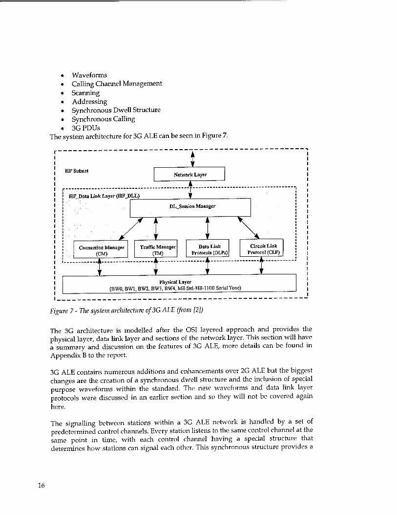
• Waveforms • Calling Channel Management • Scanning • Addressing • Synchronous Dwell Structure • Synchronous Calling • 3G PDUs
The system architecture for 3G ALE can be seen in Figure 7.
UV Subnet 1
Network Layer
HFJOata Link Layer (HF_1>LL) I DL_Session Manager
Z3 Connection Manager
(CM)
I Traffic Manager
(TM)
1 I
Data Link Protocols (DLPs)
1 Circuit Link
1'rotocol (CLP)
1 Physical Layer
(BWO, BW1, BW2, BW3, BW4, Mil-Std-188-110B Serial Tone)
Figure 7 - Tlie system architecture of3G ALE (from [2])
The 3G architecture is modelled after the OSI layered approach and provides the physical layer, data link layer and sections of the network layer. This section will have a summary and discussion on the features of 3G ALE, more details can be found in Appendix B to the report.
3G ALE contains numerous additions and enhancements over 2G ALE but the biggest changes are the creation of a synchronous dwell structure and the inclusion of special purpose waveforms within the standard. The new waveforms and data link layer protocols were discussed in an earlier section and so they will not be covered again here.
The signalling between stations within a 3G ALE network is handled by a set of predetermined control channels. Every station listens to the same control channel at the same point in time, with each control channel having a special structure that determines how stations can signal each other. This synchronous structure provides a
16

DSTO-CR-0214
great improvement in channel efficiency and speed of connection over the 2G ALE asynchronous methods.
While 3G ALE offers significant benefits over the existing 2G ALE implementation is has yet to be fielded in any commercial device. 3G ALE is not backwards compatible with 2G ALE so for a 3G ALE network to be deployed every transmitter on that network must be able to use 3G ALE. As software radios become more commonplace this issue should be lessened as changing to new protocols would only require a quick software upgrade rather than having to re-engineer the whole fleet of radios.
4.3.2 ALIS
ALIS [16] is an ALE-like protocol implemented on Rohde-Schwarz radios. It uses similar modulation techniques to MIL-STD-188-110B that can be seen in Table 6.
Table 6- Possible data rates for Rohde & Schwarz signal format
Modulation Info Redundancy Code rate FEC [% | Net data rate method bits bits [ bit/ si 8PSK WMm^M 0 No FEC 0 5400 8PSK 120 24 5/6 17 4500 8PSK ^'/■'v'-v:96 48 2/3 33 3600 8PSK ..:;'.V---'72 72 1/2 50 2700 4PSK .■•■■>P .-.36 36 1/2 50 1800 2PSK : 18 18 1/2 50 900
The creation of MIL-STD-188-llOB Appendix C removed the utility of this proprietary protocol for data transfer however as it has standardised higher speed waveforms (9600bps) that all devices can utilise.
5. Existing Products
A spreadsheet of tactical HF devices that were available on the market at the time of writing (June 2001) is provided in Appendix C. The HF devices are grouped according to manufacturer and each entry has standard fields for easy comparison of devices.
It is interesting to note the general characteristics of the devices currently on the market. 2G ALE was the most common ALE implementation, with no devices currently offering 3G ALE. Data capability is most commonly provided by MIL-STD- 188-110A with MIL-STD-188-llOB Appendix C being the most prevalent waveform used for communications above 2400bps. Very few of the devices reviewed used proprietary protocols, and where they did these proprietary protocols did not seem to offer any advantages over the newer MIL-STD standards.
17

DSTO-CR-0214
6. HF Networks
The standards discussed so far in this paper are aimed at creating a link between two HF stations. With the advent of ALE and the Internet, automatic and seamless networking for HF networks can become a reality.
MIL-STD-187-172C [18] defines an architecture for the implementation of a HF Network Controller (HFNC). It consists of an ALE controller and a MIL-STD modem coupled with a router function.
MIL-STD-187-721C defines four standard levels of HFNC functional capability: • A Level 1 HFNC has no routing capability and can only communicate with stations
within direct broadcast range.
• A Level 2 HFNC contains a simple routing and store and forward function, but it does not consider link qualities in routing decisions.
• A Level 3 HFNC adds link quality analysis and path quality exchanges to improve the routing decisions of the network.
• A Level 4 HFNC adds an Internet layer, and can therefore act as a gateway between HF and other sub-networks.
Each level defined is useful for certain parts of a HF network. For example, in Figure 8 only the gateway machines need to be level 4 devices. The other devices could be level 2 or 3, with the net controller distributing global routing tables to the network.
18

DSTO-CR-0214
ALT NET CCNTRni.. STAft-Ngr
C ~c> c
(J
Figure 8-An example HF network (from [19])
This diagram also poses another interesting question about HF networks. Should the stations be linked in a star topology (as in the diagram above) or should the network be meshed, with each radio communicating with as many stations as possible.
ALE has automated the process of creating links between stations, so the topology used does not have to rely on humans constructing it beforehand. This means it could dynamically adapt to the physical constraints placed upon it (user demand, ionospheric conditions, etc). The positioning of gateways is also central to the two topologies. A star network will centrally place the gateways, with each station being one or two hops away from the gateway. In an ad hoc meshed network arbitrary stations can be gateways (based on physical location to hardline links perhaps). Some form of protocol could be used to automatically detect gateways and route through them based on a distributed algorithm. Topologies like this are already being proposed for the wireless LAN world but the HF arena has special characteristics that should also be catered for (distance of transmissions, low rate/high latency transmissions, high errors).
Another area of investigation for HF networking is that of network management. Eric Johnson [19] suggests an adaptation of SNMP to HF networks. The adaptation reduces the bandwidth required to exchange information and optimises the message exchanges for the HF environment.
19

DSTO-CR-0214
The HF Modernisation (HFMOD) Project currently being run by the Australian Department of Defence (known as project number JP2043) is using a "hub-spoke" or "virtual hub" architecture for its network topology. Mobile nodes call into one of a group of fixed nodes that then route their call towards the final destination. The calling protocol used on the network is the MIL-STD-188-141A standard, with all mobile base stations monitoring a subset of the various fixed access points for signal levels and reliability. The proposed access method for a mobile node would route the call to the fixed node with the best LQA (Link Quality Analysis) score (LQA is a heuristic based upon signal level and reliability). One interesting aspect of the HFMOD network is that the design constrains mobile nodes from talking directly to one another; they must converse through a fixed node. This allows the fixed nodes to optimise access to the network as a whole but it does force hubbed topology on the network. The interoperability between HFMOD and standard tactical HF radios should be investigated, as HFMOD terminals require a specific set of protocols to operate.
7. Future Developments
7.1 Forthcoming Standards
The current state of the art standard for 3 kHz modems is MIL-STD-188-110B Appendix C. There was no evidence of further modem standards development.
3G ALE is still being actively developed and optimised, with MIL-STD-188-141B Change Notice 1 being the most recent document. Further development is occurring in this area, mainly with respect to testing the system. Adoption of 3G ALE by military users has yet to occur, mainly because of a lack of products in the market supporting it and the lack of compatibility with existing 2G ALE radios.
No company is publicly admitting to creating a DSSS HF radio. Boeing's developments in this area still seem to be in their infancy with no commercial product development being mentioned.
7.2 Technology Direction
The general trend seems to be for modems to try and work within the existing spectrum allocations allowed for by ITU rules. Development of serial modems that work faster or in harsher conditions is increasing. Making HF radios and HF radio networks easier to use is a big push, with developments such as 3G ALE a big leap forward.
20

DSTO-CR-0214
7.3 Market Players
Standards in the HF industry seem to be developed by a company realizing an idea, and then championing it until it is merged into a standard. Both Rockwell-Collins and Harris seem very active in driving standards development forward.
Eric Johnson ([email protected]) from the "Science Applications International Corporation" and "New Mexico State University" is also a major figure in the development and coordination of standards.
Another useful source of information about HF standards developments is the HF Industry Association (http://www.hfindustry.com/'). They meet on a regular basis and discuss the direction of the industry. Eric Johnson, Rockwell-Collins and Harris participate in this group.
8. Recommendations
8.1 Standards
Currently the standards of choice for the best performance and feature set are MIL- STD-188-141B Change Notice 1 for ALE and MIL-STD-188-llOB for data transfer. NATO is currently revising its STANAG documents relating to HF communications to align them with the relevant MIL-STD documents to maximize interoperability.
MTL-STD-188-141B (3G ALE) offers efficient, scaleable and robust Automatic Link Establishment of HF radio networks. This means less training for radio operators and the data link layer protocols also open possibilities for easy, short duration data transfers. However, the HF Modernisation Project (JP2043) has adopted MIL-STD-188- 141A as its standard (2G ALE). It may be useful for tactical radios to interoperate with JP2043 considering the long range that tactical HF radios can reasonably achieve. Legacy issues with any other existing 2G systems would also have to be understood before 3G ALE is considered.
MIL-STD-188-110B offers robust data waveforms up to a data rate of 4800bps. With Appendix C these data rates extend to 19200bps. Given the small amount of bandwidth that is available in the HF spectrum HOB offers the best use for sustained data transfers. MTL-STD-188-llOA compatibility will be required if interoperability is required with JP2043 devices.
8.2 Devices
Both Harris and Rockwell-Collins are actively developing and extending their HF devices, more so than any other companies. The AN/PRC-150(C) from Harris is currently the most feature rich tactical HF radio. Harris has indicated that they plan to
21

DSTO-CR-0214
deploy STANAG 4538 with FLSU for the AN/PRC-150(Q in the third quarter of 2001. As software defined radios are more fully realised it is expected that they will start to dominate due to the ease of upgrade.
Another device of interest is the Coachwhip for Boeing. It is currently the only device than can offer more than 19200bps over HF links. This is because it uses DSSS, which even though it can offer these higher bandwidths it can also create more problems. So while larger bandwidths may be made available the widespread use of this system in the tactical environment may not be a suitable solution.
9. References
[1] MIL-STD-188-110B, Interoperability and Performance Standards for Data Modems, U.S. Army Information Systems Engineering Command, 27 April 2000.
[2] MIL-STD-188-141B Change Notice 1, Interoperability and Performance Standards for Medium and High Frequency Radio Equipment, U.S. Army Information Systems Engineering Command, 2001.
[3] FED-STD-1045A, Telecommunications: HF Radio Automatic Link Establishment,
1993.
[4] STANAG 5066, NATO Standardization Agreement: Profile for High Frequency (HF) Radio Data Communications, 1999.
[5] STANAG 4285, NATO Standardization Agreement: Characteristics of 1200/2400/3600 bps Single Tone Modulators/Demodulators for HF Radio Links, 1990.STANAG 4539, NATO Standardization Agreement: Technical Standards for an HF Non-Hopping Waveform, Currently being ratified.
[7] STANG 4538, NATO Standardization Agreement: Technical Standards for an Automatic Radio Control System (ARCS) for HF Communication Links, Currently being ratified.
[8] Steven L. Karty, November 2000, Email Over High Frequency (HF) Radio: Filling the Communications Gap During Unexpected Telephone Outages, Office of the Manage National Communications System Technical Notes, Volume 7, Number 6.
[9] FED-STD-1052, Telecommunications: HF Radio Modems, 1996.
[10] PACTOR-II Homepage, http://wvvvv.scs-ptc.com/avvgn.html, June 2001.
[11] CLOVER-2000 Homepage, http:/ / vvwvv.hcilcomm.com/clover2000.htm, June 2001.
22

DSTO-CR-0214
[12] Datron World Communications, A Discussion of Automatic link Establishment (ALE), http://www.dtwc.com/Products/pdfs/ale.pdf, June 2001.
[13] Harris Communications, 1996, Radio Communications in the Digital Age: Volume One: HF Technology, Harris Communications, USA.
[14] Eric E. Johnson, 1998, Third-Generation HF Automation in MIL-STD-188-141.
[15] NTIA, 1998, High Frequency Radio Automatic Link Establishment (ALE) Application Handbook, http://www.its.bldrdoc.gov/pub/oa-rpt/hf-ale/handbook/.
[16] HF-Waveforms, http://www.rohde- schwarz.com/www/dev center.nsf/html/113321, June 2001.
[17] Don Herskovitz, May 2001, A Sampling of Tactical Transceivers, Journal of Electronic Defence, Volume 23, Number 6.
[18] MIL-STD-187-721C, Planning and Guidance Standard for Automated Control Applique for HF Radio, November 1994.
[19] Eric E. Johnson, 1995, HF Radio in the International Information Infrastructure, HF '95: Nordic Shortwave Radio Conference proceedings.
[20] Paul Marland, STANAG 5066 - THE WORLD'S FIRST IMPLEMENTATION, Marconi Communications, HF 98 Proceedings.
[21] US Military Communications-Electronics Board, P_MUL - A Protocol for Reliable Multicast Messaging in Bandwidth Constrined and Delayed Acknowledgement (EMCON) Environments, ACP142 Version 1, August 9,2001.
[22] Preiss M., "The Measurement and Analysis of Several HF Links Using the DSTO Replay Simulator", 4th UK/Australian International Symposium on DSP for Communication Systems, pp 70-77, Perth, 23-26 September.
[23] Sicom Incorporated, COACHWHIP HF/VHFAIHF Spread Spectrum High Rate Digital Data/Video Transceiver, 1999.
23

DSTO-CR-0214
Appendix A: HF Primer
This appendix will give the reader some background information on various HF concepts used within this paper. Its purpose is to provide information about some specific concepts and effects observed in HF communications. Skipping this appendix is suggested if the reader already has knowledge of HF communication fundamentals.
A.l. The HF Channel
HF stands for High Frequency. The term HF refers to electromagnetic (EM) radiation in the 3 to 30 MHz frequency range, though many military HF radios operate over a wider range of frequencies. Frequencies within this range propagate via three main methods, sky wave, direct wave and ground wave.
A.1.1 Propagation
• Sky Wave
Sky wave propagation refers to "reflecting" the EM radiation off the ionosphere (strictly speaking it is bent via a refraction process). By reflecting the radiation off the ionosphere the distance the radiation can travel is greatly increased as can be seen in the diagram below.
Frequency > Critical
Ionosphere
Figure 9 - Sky wave radio propagation
This greater range comes at a cost however. The ionosphere is a very dynamic region that is dependent on the Sun and its cycles. Propagation via the ionosphere is also
24

DSTO-CR-0214
frequency and incident angle dependent, with {frequencies, angle} pairs above a critical value (such as TV broadcasts) passing straight through.
• Surface Wave
Surface wave (also known as ground wave) propagation is another method by which radio waves can propagate. The waves travel along the surface of the earth, with the distance travelled being related to the conductivity and permittivity of the terrain between the two antennas.
• Direct Wave
In this mode of propagation there is a direct line-of-sight between the two antennas. Direct wave propagation is limited by the curvature of the earth, so to increase transmission distances the antennas must be raised in height.
A.1.2 Effects
• Multipath
Multipath propagation occurs when a single wave takes multiple paths to the receiving antenna. The effect can be seen in the diagram below.
Multipath Reception
Figure 10 - Multipath example
In this example the receiving station receives three versions of the same waveform that the transmitter sent. The multiple waves interfere with each other causing losses and gains in the received signal. This effect occurs in 3 dimensions (four if time is included) and it can be extremely complicated to predict.
25

DSTO-CR-0214
• Noise
Noise is an undesired disturbance within the frequency band being used. Noise can be considered as a source injecting a random signal into a system. Man-made or natural systems can generate it. A particular type of noise generally considered by communication systems is Additive White Gaussian Noise (AWGN). AWGN has the characteristics of uniform and continuous noise levels across all frequencies within a frequency band. The energy introduced by this noise is also constant across the frequency band. In the HF spectrum the noise present is not of AWGN nature however modem manufacturers use it as a basis for comparing devices.
• Fading
Fading is the loss of signal power due to atmospheric or man-made effects, with the main constituent of fading being multipath effects. The ionosphere is the cause of most atmospheric effects. This is due to the varying transmission characteristics in each layer caused by changing electron densities. The amount of fading across a single 3 kHz band can be quite pronounced so any transmissions must take this effect into account.
• Doppler Shift
Doppler shift is the change in frequency of a wave due to the relative movement of either the transmitter, receiver or transmission media. It causes the absolute frequency of a received signal to drift away from the transmitted frequency. For HF communications the movement of the ionosphere can cause significant frequency shifts.
A.2. Modulation
Modulation is the process of encoding an information signal onto a carrier signal to produce an output signal that conforms to certain requirements such as the centre frequency and bandwidth. There are various modulation schemes, each of which seeks to counter certain channel effects to achieve a desired performance level. A few schemes commonly used for HF channels will now be discussed.
A.2.1 AM
Amplitude Modulation (AM) is one of the simplest forms of modulation. A signal waveform modulates the amplitude of a constant tone. The envelope of the resulting waveform contains the modulated signal, as can be seen in the diagram below.
26

DSTO-CR-0214
Constant tone
Signal
Modulated Waveform
Figure 11- AM Modulation
A.2.2 SSB
Single SideBand Amplitude Modulation (SSB-AM) is an extension of simple AM modulation, and it is commonly referred to as SSB. SSB operates by modulating the signal onto a "complex envelope" tone, which essentially shifts the baseband signal up to the carrier frequency. SSB produces a modulated waveform that uses half the bandwidth as compared to AM techniques.
SSB is a very popular method for the transmission of voice over radio links.
A.2.3 FSK
Frequency Shift Keying (FSK) is the modulation scheme where the information signal shifts the output frequency between a number of predetermined values within the assigned frequency band. An example is the FSK scheme used by 2G ALE. It consists of 8 separate tones, with each tone representing a particular 3-bit value.
A.2.4 PSK
Phase Shift Keying (PSK) is similar to FSK. Instead of having different frequencies it uses different phases of a single tone. Phase is the relative position in time of a waveform within a cycle of possible values.
A.2.5 QAM
Quadrature Amplitude Modulation (QAM) is a modulation scheme where both the phase and amplitude of the signal define the value being transmitted. The diagram below shows a simple 16-symbol QAM constellation. Each symbol transmitted corresponds to one point within this diagram. The distance from the origin determines the amplitude and the rotation from the positive "I" axis determines the phase.
27

DSTO-CR-0214
X X - X X
X X - X X
H—H4— I X x -- X X
X X-- X X
Figure 12-a 16 symbol QAM constellation
A.3. Spread Spectrum Transmission Methods
A.3.1 Frequency Hopping
Frequency hopping radios jump through a series of radio channels in a known, albeit potentially complex, pattern. Both the transmitter and the receiver must follow the same pattern so the channels being scanned coincide. This hopping provides many benefits such as:
• Low probability of intercept (LPI) due to the limited time the radio spends on one channel.
• Resistance to narrow band interference due to the large number of different frequencies used.
• Multiple access enabled by different nets using different hopping sequences within the same channel group.
A.3.2 DSSS
Direct Sequence Spread Spectrum (DSSS) is a modulation scheme whereby a low rate signal is modulated with a high rate pseudorandom sequence. This produces a high bandwidth signal, but the pseudorandom sequence causes only small amounts of interference (noise) for a conventionally modulated signal.
A.4. Bit rate versus Symbol rate
The example for 8-ary FSK draws out the concept of bits versus symbols on a channel. Each symbol transmitted by the modem corresponds to a 3-bit value, so the bit rate of the modem would be 3 times the symbol rate.
28

DSTO-CR-0214
A.5. ARQ
Automatic Repeat reQuest (ARQ) is a family of protocols that allow repeating a transmission when requested by the receiving station. It can be thought of as the mechanism by which packets get sent reliably by the network. HF's unique characteristics mean that the ARQ protocols used by HF modems must be tailored to efficiently handle the channel. In particular the low data rate and high error rate mean small packets and smart error recovery must be performed.
A.6. Coding
A.6.1 Error Detection and Correction
Data transmission devices depend on the ability to detect errors so that they can provide reliable delivery of data. This is usually accomplished by using a hashing algorithm to produce a fingerprint of the data in the packet. If the data is corrupted in transmission then hopefully the corrupted data will no longer hash to the value stored in the hash field. This hashing relies on probabilities not certainties to detect errors.
The number of errors detectable by a hashing code (or any code for that matter) is dependent on its length. For every bit in the error detection field a 1-bit error in the data packet can be detected. So high error channels require lots of error detection bits to detect errors.
Detection only handles half the problem however. Once the error is detected the correct data must then be obtained however. A simple method (used on the Internet) is to simply re-send that corrupt packet (ie ARQ). This has two problems for the HF environment however. The low data rate means re-sending data wastes a valuable resource that is already in demand. It is also resending that data across the same high error channel so there is a high likelihood of an error occurring in the resent packet, thereby causing the same problem yet again.
A process known as Forward Error Correction (FEC) solves this problem. FEC corrects errors in packets using extra redundant (FEC) information. The number of errors that can be corrected by FEC is equal to about half the number of FEC bits sent. For example, sending 2 bits of FEC per byte means that 1 error in that byte can be corrected. The 2400bps 110A waveform for example uses Vz rate FEC. For every 1 data bit a FEC bit is also added, meaning that Vz of the packet's data contents can be possibly corrected. The amount of FEC and the timeouts of the ARQ protocol can be balanced off against each other to maximise the amount of useful throughput of the channel.
A.6.2 Interleaving
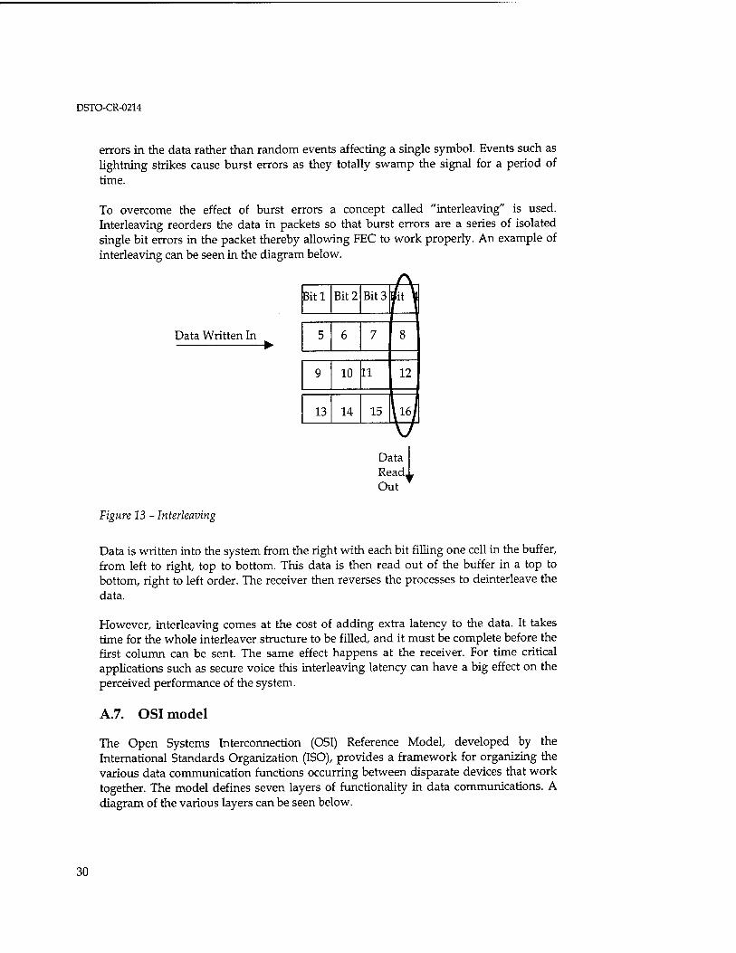
FEC coding and error detection in general are based around correcting random errors in data, however HF channels often produce burst errors. Burst errors are runs of
29
DSTO-CR-0214
errors in the data rather than random events affecting a single symbol. Events such as lightning strikes cause burst errors as they totally swamp the signal for a period of time.
To overcome the effect of burst errors a concept called "interleaving" is used. Interleaving reorders the data in packets so that burst errors are a series of isolated single bit errors in the packet thereby allowing FEC to work properly. An example of interleaving can be seen in the diagram below.
Data Written In
A Bitl Bit 2 Bit 3 A
5 6 7 8
9 10 11 12
13 14 15 U Data Read, Out
Figure 13 - Interleaving
Data is written into the system from the right with each bit filling one cell in the buffer, from left to right, top to bottom. This data is then read out of the buffer in a top to bottom, right to left order. The receiver then reverses the processes to deinterleave the data.
However, interleaving comes at the cost of adding extra latency to the data. It takes time for the whole interleaver structure to be filled, and it must be complete before the first column can be sent. The same effect happens at the receiver. For time critical applications such as secure voice this interleaving latency can have a big effect on the perceived performance of the system.
A.7. OSI model
The Open Systems Interconnection (OSI) Reference Model, developed by the International Standards Organization (ISO), provides a framework for organizing the various data communication functions occurring between disparate devices that work together. The model defines seven layers of functionality in data communications. A diagram of the various layers can be seen below.
30

DSTO-CR-0214
OS! Model ^ —--I
Application
Praentation
Seaion
Ttansport
Netvradc
Data Link
Physical
Figure 14 - The OSI model
This paper covers details from the physical and data link layers, with brief excursions to higher layers were needed.
31

DSTO-CR-0214
Appendix B: 3G ALE Details
This appendix contains a detailed summary of the 3G ALE specification.
B.l. Waveforms
The 3G ALE standard contains a definition for 4 waveform types that are detailed in the table below.
Table 7 - 3G ALE waveform types (from [2])
Wave used tor form
burst duration p.iylo.id preamble
BWO 3G-ALE 613.33 ms 26 bits 160.00 ms rate = 1/2, 4x13 block 16-ary 1/ yb
PDUs 1472 symbols
PSK 384 PSK symbols
k = 7 convolutio nal (no flush bits)
orthogonal Walsh function
BW1 Traffic 1.30667 48 bits 240.00 ms rate = 1/3, 16x9 block 16-ary 1/144 Managern seconds 576 PSK k = 9 orthogonal ent PDUs; 3136 PSK symbols convolutio Walsh HDL symbols nal (no function acknowled flush bits) gement PDUs
BW2 HDL 640 + (n *400) n*1881 26.67 ms rate = 1/4, none 32 unknown/ variable: traffic data ms bits 64 PSK k = 8 16 known 1/1 to PDUs 1536 + (n*960) symbols convolutio 1/4
PSK (for nal (7 symbols, equalizer flush bits) n = 3, 6,' 12, or training) 24
BW3 LDL traffic 373.33 + 8n+25 266.67 ms rate = 1/2, Convolutional 16-ary variable:
data PDUs (n*13.33) ms bits 640 PSK k = 7 block orthogonal 1 / 12 to 32n + 896 PSK symbols convolutio Walsh 1/24 symbols, n = nal (7 function 32*m, flush bits) m = 1,2,. .., 16
BW4 LDL acknow- ledgement PDUs
640.00 ms 1536 symbols
PSK 2 bits none none none 4-ary
orthogonal Walsh function
1 / 1920
It is interesting to see the effect of having such a robust waveform for the connection setup PDU (the BWO waveform). As can be seen in the plot below the probability of connection under bad conditions is improved by about 7dB over the 8-ary FSK methods used in 2G ALE.
32

DSTO-CR-0214
-♦-8W0AWGN
-■-ßWüPoor
-A-8W0GüüLI
-«-MIL-ALEAWGN
-•-MlL-ALEPoor
-H—MIL-ALE Cocci
■113 ■1Ü 1.ü
SNR(dB)
Figure 15 - Probability of linking for various ALE waveforms (from [15])
B.2. Calling Channel Management
Assignments of calling and traffic channels to 3G devices may either have static lists of frequencies assigned to them or they can have lists automatically provided by external systems. These external systems could be devices such as ionospheric sounding networks. These external lists must be identical across the whole network for 3G ALE to operate correctly.
MIL-STD-188-141B also defines an Automatic link maintenance mode that enables radios to renegotiate the traffic channel being used once the link has been created.
B.3. Scanning
3G ALE can use a synchronous mode of scanning radio frequencies where every station on the network changes its calling frequency at the same point in time (to the accuracy of the timing on the network, which the 3G standard dictates shall not exceed 50ms). This provides a common signalling channel that all radios on that network can use to initiate connections. There is no requirement that all stations listen to the same calling channel at the same time however. Spreading radios across different scanning patterns enables multiple nets to share the same frequencies but at different times (a form of time division multiplexing). The scan rate of the calling channels is directly related to the size of the synchronous dwell structure (described below). For MIL-STD- 188-141B Change Notice 1 the dwell time is 5.4 s.
33

Synchronisation of the stations can be performed by two methods, external synchronisation (through devices such as GPS or the NTP protocol) or through over- the-air synchronisation. MIL-STD-188-141B recommends that external synchronisation be used.
The network can be partitioned into smaller networks by giving each sub-network a different scanning list. This essentially distributes the sub-networks in frequency and time, which can greatly reduce the chance of collision on a calling channel. This is especially important under conditions of high traffic load. The set of radios that monitor the same channel list are called a dwell group.
B.4. Addressing
3G PDUs contain an 11-bit address that is divided into a 6 bit member field and a 5 bit
group field.
6 bits 5 bits
Member# Group#
Figure 16-PDU address structure (from [2])
The member field is used to identify specific stations, with a range of addresses (llllxx) reserved for temporary use from external stations calling into the network. The group field defines the dwell group that the station belongs to. Up to 32 dwell groups of up to 60 members each are supported (1920 stations per net).
B.5. Synchronous Dwell Structure
The duration of the Synchronous dwell structure is 5.4s (900ms per slot). The dwell structure can be seen below.
SlotO Slotl Slot 2 Slot 3 Slot 4 Slot 5
\ \ \ '
i m l
\ \ \
Used only for calls \ \
Used only for a traffic t
monitoring hanncl Uscdf< ir calls and rest
Us<
wnscs on
d for re d notifi
sponscs cations
Figure 17- Synchronous Dwell Structure
34

DSTO-CR-0214
During slot 0 radios to tune to the calling channel frequency and radios that wish to transmit can tune to the transmission frequency. The rest of the slot 0 is used by the radio to listen for traffic. Scanning radios are listening to adjacent traffic channels for traffic and stations that wish to transmit confirm that the frequency they have chosen is free.
Slots 1 thru 4 are then used to place calls by stations. Slot 5 is reserved for LEJHandshake, LE_Notification, and LE_Broadcast PDUs. This reservation is performed to increase the systems performance, the original MIL-STD-188-141B specification defined only 5 slots (0-4).
B.6. Synchronous Calling
The Synchronous calling protocol seeks to determine a suitable channel so that two stations can transmit information on a separate traffic frequency. The calling channel is similar to the signalling channel in a GSM system. It offers a shared signalling Carrier Sense Multiple Access (CSMA) channel for the network to negotiate connections between stations. 3G-ALE calls indicate the type of traffic to be carried (from various broad classes), and the first traffic channel(s) that will support this grade of service will be used. Note that the default system does not spend time seeking the best channels for traffic.
When a point-to-point call commences a calling station will randomly (using a non- uniform set of probabilities which bias towards higher priority calls) pick a calling slot within the next dwell time. In slot 0 of that dwell time the calling radio will listen to nearby traffic channels and choose one that is free. If the chosen slot is not slotl then the radio will listen to other slots that may pre-empt it. If it detects another handshake in earlier slots it will defer its call until that transaction is complete. Otherwise it sends a probe PDU in the chosen slot with the address of the receiving station and listens for the response in the next slot. Note that slot 5 is only for responding to handshakes, it cannot be used to start a call.
When the receiving channel hears the probe PDU (which identifies the station by the address field) it responds in the next timeslot in the dwell structure. The receiving station sends a handshake PDU back to the calling station that can indicate a good traffic channel to use. If the calling station then responds with a good traffic channel also the radios move to the selected traffic channels and start communications. If the channels selected are unsuitable the calling station can respond with a "continue handshake" handshake PDU. This PDU causes the handshaking session to continue in the next calling timeslot, repeating the above process. This will continue until either a suitable channel is found or once a maximum number of tries are reached.
A graphical representation of the process can be found below. Note that this diagram shows a dwell structure of only 4 slots, not the 5 defined in the latest standard.
35

DSTO-CR-0214
NOTE: This drawing is nol to scale
Calk» h
Cillod Ix
Legend
Sorvlco Hoquoat: ■Sund .PUT "mo: CFJ"
Routwo Pronty
Control Frequencies
Control Control Control Control Freq Freq Freq Freq 12 3 4
Traffic Frequencies
Traffic Freq
1
Traffic Traffic Freq Freq
2 3
Traffic Freq
4
Gallon LE Call rou
la uta lrom*to2to3tjS
Called: LE Hanmiiako POU
Link Id 3n "CommoiKoonTF3"
Caller. LE Call rou
from ab 2 to Not Link Roloaso
Caller: LE HandUiako PDU
Link id fti Itoloa&o IFy
Figure 18 - Synchronous point-to-point connection setup example (from [2])
36

DSTO-CR-0214
B.7. 3G PDUs
Seven (7) PDUs are defined for use in 3G ALE. The two of most interest are the probe and handshake PDU.
if.caipou
PDU
LE.fWikaim
m
LE.nmoOHMil
PDU
BnumslPDU
LEJlrcgaraa
Le..!JC3TniNK)
Cat PDU
6 1 6 6 4
. ClÜDdUoiKKB*
rail ilia) Cdl*» Cakrtalar« ijtmCnapt CRC
8 1 / A
ii o u*a Cornnond Anju»ii(«9.,ai« CRC
6 J B ii 4
< » I Mill Cikr Stilus Goto Uosbcr ti takräraup* CRC
i i i «j A
i) i mo firaQmlty äqn Otfesl (SC
i : a 4 i 8
o : '.oi 1) ilTOfGlttU« 3mll SHU CRC
i i i / it
» ' ua CMtskmn CaST'd» Carnal cat
i i 11 1«
ii i '• 11 II c ilbd Stilnn Affllnu cat
Figure 19 - 3G ALE PDUs (from [2]).
The probe PDU (LE_Call) contains the station being called, the call type, the address of the calling station and its dwell group. The call type field defines the class of traffic to be used for the call. This is used by the radios to select an appropriate channel for the requirements of the call.
The handshake PDU (LE_Handshake) is sent after a probe PDU. The possible responses carried by the packet are:
37

DSTO-CR-0214
Table 8 - Command field for handshake PDUs (from [2])
5 6 7
Command Continue Handshake
Commence Traffic Setup
Voice Traffic
Link Release
Sync Check
(reserved) (reserved) Abort Handshake
Description Argument
Channel
Channel
The handshake will continue for at least Reason another two-way handshake (on the next assigned called station dwell frequency when operating in synchronous mode). This is the final command sent on a calling channel. The argument is the channel number on which the responding station will (or should) listen for traffic setup. Following this command, all stations proceed to that traffic channel. This command directs called station(s) to tune to a traffic channel and commence voice traffic. The argument is the channel number. Following this command, the calling station will be first to speak. (Uni- and multicast only) This command informs all listening stations that the specified traffic channel is no longer in use by the sending station. This command directs the called station to measure and report synchronization offset back to the calling station. Used in synchronization management protocol (C.5.2.7).
Channel
Quality or Slot
This command immediately terminates the handshake and needs no response. It is analogous to the TWAS preamble in 2G ALE.
Reason
B.8. Data Link Layer
There are two data link layer protocols defined in MIL-STD-188-141B: High rate Data Link protocol (HDL) and Low rate Data Link protocol (LDL). Both data link protocols use memory combining and do not require data rate adaptation. Data transfers occur once a radio connection has already been created by earlier stages of ALE.
38
DSTO-CR-0214
HDL is used for large message transfer on a good channel. It provides point-to-point communications with acknowledgement of datagrams and selective retransmission of corrupt datagrams (ARQ). For every data PDU sent the receiving station sends an ACK packet.
LDL provides low rate reliable, acknowledged transmission of data PDUs. The LDL protocol is designed to perform well under adverse channel conditions.
39

DSTO-CR-0214
Appendix C: HF communications devices
Manufacturer Product Name Frequency Range ALE STD Power Output Modem
Datron
Usage
■■pmio Manpack
Datasheet location Other MIL-STD-188/110A (50 to 4800bps), STANAG 4285,
1.6 to 30 MHz 2G 20/100/400 W STANAG 4529
http://iuZLW.dtzuc.com/Products/pdfs/rt7110.pdf
PRC1099A 1.6 to 30 MHz 2G 20/100/400 W
Manpack http://zozoio.dtzoc.cotn/Prodiicts/pdfs/prcl099a.pdf
Harris RF-5710A- MD001
HOB Appendix C (9600 and 12800bps), 110A (50 to 4800bps), STANAG 4285, STANAG 4529, STANAG 5065
Strategic http://ioioio.rfcomm.lwrris.cojn/defense-comm/data/rf-571Qa.pdf
RF-5710A- MD002
Strategic
110A (50 to 4800bps), STANAG 4285, STANAG 4529,
http://mni\rtcomm.lwrris.com/rfefensc-comm/data/rf-57Wa-mdQl)2j^
AN/PRC-138 1.6 to 60 MHz
ViaRF- 5161-01 add-on 1/5/20 W
110A (75 to 2400bps), 110A Appendix B (2400bps)
Manpack http://icim\rtamiiii.harris.LVM/(1efense-coiinii/tnctical/miprc-l38.pdf
AN/PRC-138B/C 1.6 to 60 MHz
110A (75 to 4800bps), STANAG
2G 1/5/20 W 4285
Manpack htlp://n,icu\ifcoinin.lniiiis.(\vii/deti'n$e-coiuiii/ltictictil/aiiprc-l 38bc.pdf
RF-5022T/T(E) 1.6 to 30 MHz
Via RF- 5122ALE(20/125/400/ E) add-on 1000 W Via RF-5285MD(E)
Vehicle lUtp://jon,zr.rtcoiiniLlnims.covi/ih'fenst'-coiiiiu/tticticnl/rt'-5022iii'.pdf'
40

DSTO-CR-0214
mF-5122ALE(E) llApplique for ljAN/PRC-138, " ;RF-5800H or RF- J7210 Harris Iradios
2G
http://ivwio.rfcomm.harris.com/defense-comm/tactical/rf-5122ale-e.pdf
WF-5285MDE § Applique for jAN/PRC-138, RF-5800HorRF-
;7210 Harris radios
110A (75 to 4800bps), STANAG 4285,110A Appendix B (75 to 2400bps)
http://www.rfcomm.harris.com/defense-comm/tactical/rf-5285mde.pdf
RF-5800H-MP 1.6 to 60 MHz 2G 1/5/20 W
HOB Appendix C (9600bps), 110A Appendix B (2400bps), 110A (2400bps), STANAG 4285, STANAG 4415
Manpack http://www.rfcomm.harris.com/defense-comm/tactical/rf-5800h-mp.pdf
mF-6010
Vehicle http://www.rfcomm.liarris.com/defense- comm/tactical/rf-60l0.pdf
HOB Appendix C (9600bps) a Tactical Network Access Hub, provides IP across HF/VHF networks
AN/PRC-150(C) 1.6 to 60 MHz 2G 1/5/20 W
Manpack
HOB Appendix C (9600bps), 110A Appendix B (2400bps), 110A (2400bps), STANAG 4285, STANAG 4415 same as RF-5800h except that it comes with type 1 encryption, STANAG 4538 FLSUin3Q,2001
41

DSTO-CR-0214
• .. ...-..-.. . ; — 110A(4800bps),
; : , , STANAG4285, Rohde & .;■' 2G or STANAG 4481, Schwarz RS-150T 1.5 to 30 MHz ALIS 150W proprietary 5400bps
'r'";;":;,;';y^-'';;^yehicle http://ivww.rohde-ichwarz.cow/www/dez' center.n?f/litml/113212framc
^■■'^'s'ii^MiaOOOH 1.5 to 108 MHz ? 10/50 W ? ■,- ■•;■:,'■...';.;:■:' http://www.rohde-
■ ■•■'.•;':.■■■ Vehicle schwarz.com/www/download files.nsf/ftle/M5tr mil.pdf/$fde/M3tr mil.pdf 2G or HOA (4800bps),
'XK2100 1.5 to 30 MHz ALIS 150 W proprietary 5400bps httirJ/wunv.rohde-
;.; V; Vehicle xhwarz.com/www/doivnlond files.mf/file/XklOOO 24 web.pdfMlc/XklOOO 24 wcb.pdf
Wave Science
Rockwell- Collins
WS-1000
Palmtop
2G
httv://wiviv.ivavescience.com/wsl000-2.asri
HOA (4800bps), HOB (9600bps) PCMCIA form factor HOA (4800bps), HOB Appendix C (9600bps), HOB Appendix F (19200bps), ISB mode (19200bps), STANAG 4285 Q9600
Vehicle http://iimmKcollins.wckivcllxom/ecat/^/O9600.htnil?smcnu=Wl
ALE
Vehicle
2G Compatible with the following Rockwell-Collins radios: HF-9000,
httvV/uww.collms.rockzoell.com/eoit/GS/ALE.html 718U/ARC-174, ?smemi=10l ARC-190 and HF-80
AN/VRC-100
Vehicle
MDM-2501
PC
2 to 30 MHz
2G plus 141B Appendi x A quick HOA (4800bps), call 10/50/100 W STANAG 4285
http://www.collinf.rocturl!.coin/ecat/'^/AN VRC-10n.html?*mcmt = 101
http://www.collinf.rockwell.coin/ecat/GS/MP\l- 2501.html?<menu = 101
HOA (4800bps), STANAG 4285, HOA Appendix A+B+C, TADIL-B 2 slot PC-AT style interface
42

DSTO-CR-0214
Grintek *;,;', TR2400
Manpack
1.6 to 30 MHz
2G, "quick ALE" option to 100 W
110A (4800bps), STANAG 4285
http://ioiuw.sadid.co.za/SADID]_6/files/c pap.es/pl06.html
Motorola- ^MICOM-2E
'"' -:,•', Vehicle
1.6 to 30 MHz 2G to 125 W
http://www.motorola.com/LMPS/RNSG/mobiles/micom/micom_2e/tech.htm
Thales Communica tions TRC-3400
-S;;§!^J^t©i Vehicle/ Manpack
Panther H Vehicle/ Manpack
■Syncal 2000 ■ ■PRM4790
Vehicle
1.6 to 30 MHz
Skymaste r (details: http://iuw w.comsys. thomson- csf.com/ou r act/radioto 125 W, to M act/sky 20W Manpack STANAG 4285, mas.htm) version 5400bps FSK
http://www.comsys.thomson-csf.com/our act/radio/hf act/3400.htm
5/25/50 (Manpack), 5/25/100/400
? (Vehicle) ? http://www. thales- defence.co.uk/business/commsMs/comms/tactical/vanther h/default.htm
1.5 to 30 MHz
2G 20/100 W ViaMA4798 1.6 to 30 MHz h ttp://wiow. thales- defence.co.uk/business/commsys/coinms/tactical/syncal 2000/'default.htm
MA4798 2G 3600bps \ittp://www. tliales-
Vehicle defence.co.uk/bitsiness/commsys/comms/tacticalMincal 20Q0/ma4798/default.litm
43

DISTRIBUTION LIST
Tactical High Frequency Communications in the Land Arena • The Current State of the Art
A.B. Reynolds and W.D. Blair
AUSTRALIA
DEFENCE ORGANISATION
Task Sponsor DGC4
S&T Program Chief Defence Scientist ] FAS Science Policy J- shared copy AS Science Corporate Management 1 Director General Science Policy Development / Counsellor Defence Science, London (Doc Data Sheet) Counsellor Defence Science, Washington (Doc Data Sheet) Scientific Adviser to MRDC Thailand (Doc Data Sheet) Scientific Adviser Joint Navy Scientific Adviser (Doc Data Sheet and distribution list only) Scientific Adviser - Army Air Force Scientific Adviser Director Trials
Aeronautical and Maritime Research Laboratory Director
Electronics and Surveillance Research Laboratory Director (Doc Data Sheet and distribution list only)
Chief of Communications Division Research Leader, MIN Branch Head Network Architectures Group Head Network Management Group Head Wireless Systems Group W.D. Blair A.B. Reynolds J.T. Ball W. Zhang M. Scholz Chief of Land Operations Division Research Leader, LS Branch F. Bowden Research Leader, JS Branch
DSTO Library Library Fishermens Bend (Doc Data sheet only)
Library Maribyrnong (Doc Data sheet only) Library Salisbury Australian Archives Library, MOD, Pyrmont (Doc Data sheet only) *US Defence Technical Information Center, 2 copies *UK Defence Research Information Centre, 2 copies *Canada Defence Scientific Information Service, 1 copy *NZ Defence Information Centre, 1 copy National Library of Australia, 1 copy
Capability Systems Staff Director General Maritime Development (Doc Data Sheet only Director General Land Development Director General Aerospace Development (Doc Data Sheet only)
Knowledge Staff Director General Command, Control, Communications and Computers (DGC4)
(Doc Data Sheet only)
Army Stuart Schnaars, ABCA Standardisation Officer, Tobruk Barracks, Puckapunyal,
3662 (4 copies) SO (Science), DJFHQ(L), MILPO Enoggera, Queensland 4051 Army Communications Training Centre
Headquarters Development Wing
Intelligence Program DGSTA Defence Intelligence Organisation Manager, Information Centre, Defence Intelligence Organisation
Acquisitions Program SPO(Director) Battlespace Communications Systems PDJP2072 DHFMP PDBCSS Land Engineering Agency (2 Copies: Library and G. Lampard)
Corporate Support Program (libraries} OIC TRS, Defence Regional Library, Canberra (Doc Data Sheet)
UNIVERSITIES AND COLLEGES
Australian Defence Force Academy Library Head of Aerospace and Mechanical Engineering
Senior Librarian, Hargrave Library, Monash University (Doc Data Sheet) Librarian, Flinders University
OTHER ORGANISATIONS

NASA (Canberra) AGPS State Library of South Australia
OUTSIDE AUSTRALIA
ABSTRACTING AND INFORMATION ORGANISATIONS INSPEC: Acquisitions Section Institution of Electrical Engineers Library, Chemical Abstracts Reference Service Engineering Societies Library, US Materials Information, Cambridge Scientific Abstracts, US Documents Librarian, The Center for Research Libraries, US
INFORMATION EXCHANGE AGREEMENT PARTNERS Acquisitions Unit, Science Reference and Information Service, UK Library - Exchange Desk, National Institute of Standards and Technology, US
SPARES (5 copies)
Total number of copies: 64
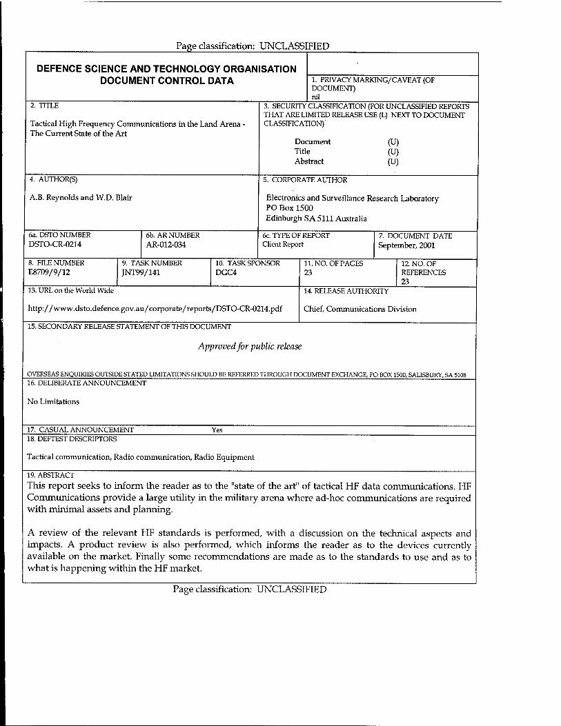
Page classification: UNCLASSIFIED
DEFENCE SCIENCE AND TECHNOLOGY ORGANISATION DOCUMENT CONTROL DATA 1. PRIVACY MARKING/CAVEAT (OF
DOCUMENT) nil
2. TITLE
Tactical High Frequency Communications in the Land Arena - The Current State of the Art
3. SECURITY CLASSIFICATION (FOR UNCLASSIFIED REPORTS THAT ARE LIMITED RELEASE USE (L) NEXT TO DOCUMENT CLASSIFICATION)
Document Title Abstract
(U) (U) (U)
4. AUTHOR(S)
A.B. Reynolds and W.D. Blair
5. CORPORATE AUTHOR
Electronics and Surveillance Research Laboratory PO Box 1500
Edinburgh SA 5111 Australia
6a. DSTO NUMBER DSTO-CR-0214
6b. AR NUMBER AR-012-034
6c. TYPE OF REPORT Client Report
7. DOCUMENT DATE September, 2001
8. FILE NUMBER E8709/9/12
9. TASK NUMBER JNT99/141
10. TASK SPONSOR DGC4
11. NO. OF PAGES 23
12. NO. OF REFERENCES 23
13. URL on the World Wide
http://www.dsto.defence.gov.au/corporate/reports/DSTO-CR-0214.pdf
14. RELEASE AUTHORITY
Chief, Communications Division
15. SECONDARY RELEASE STATEMENT OF THIS DOCUMENT
Approved for public release
OVERSEAS ENQUIRIES OUTSIDE STATED LIMITATIONS SHOULD BE REFERRED THROUGH DOCUMENT EXCHANGE, PO BOX 1500, SALISBURY, SA 5108 16. DELIBERATE ANNOUNCEMENT
No Limitations
17. CASUAL ANNOUNCEMENT Yes 18. DEFTEST DESCRIPTORS
Tactical communication, Radio communication, Radio Equipment
19. ABSTRACT
This report seeks to inform the reader as to the "state of the art" of tactical HF data communications. HF Communications provide a large utility in the military arena where ad-hoc communications are required with minirnal assets and planning.
A review of the relevant HF standards is performed, with a discussion on the technical aspects and impacts. A product review is also performed, which informs the reader as to the devices currently available on the market. Finally some recommendations are made as to the standards to use and as to what is happening within the HF market.
Page classification: UNCLASSIFIED