Tactical Decision Aids and Situational Awareness Educational Notes/RTO-EN... · Societa’ Italiana...
96
RTO-EN-019 AC/323(SCI-113)TP/41 NORTH ATLANTIC TREATY ORGANISATION RESEARCH AND TECHNOLOGY ORGANISATION BP 25, 7 RUE ANCELLE, F-92201 NEUILLY-SUR-SEINE CEDEX, FRANCE RTO LECTURE SERIES 227 Tactical Decision Aids and Situational Awareness (Les aides ` a la prise de d´ ecisions tactiques et la connaissance de la situation des forces) The material in this publication was assembled to support a Lecture Series under the sponsorship of the Systems Concepts and Integration Panel (SCI) and the Consultant and Exchange Programme of RTA presented on 1-2 November 2001 in Amsterdam, The Netherlands, 8-9 November 2001, Sofia, Bulgaria, 12-13 November 2001 in Madrid, Spain and 19-20 November 2001, Maryland, United States. Published January 2002 Distribution and Availability on Back Cover RTO-EN-019
-
Upload
hoangkhuong -
Category
Documents
-
view
219 -
download
0
Transcript of Tactical Decision Aids and Situational Awareness Educational Notes/RTO-EN... · Societa’ Italiana...

RTO-EN-019AC/323(SCI-113)TP/41
NORTH ATLANTIC TREATY ORGANISATION
RESEARCH AND TECHNOLOGY ORGANISATION
BP 25, 7 RUE ANCELLE, F-92201 NEUILLY-SUR-SEINE CEDEX, FRANCE
RTO LECTURE SERIES 227
Tactical Decision Aids and SituationalAwareness(Les aides a la prise de decisions tactiques et la connaissancede la situation des forces)
The material in this publication was assembled to support a Lecture Series under the sponsorshipof the Systems Concepts and Integration Panel (SCI) and the Consultant and ExchangeProgramme of RTA presented on 1-2 November 2001 in Amsterdam, The Netherlands,8-9 November 2001, Sofia, Bulgaria, 12-13 November 2001 in Madrid, Spain and19-20 November 2001, Maryland, United States.
Published January 2002
Distribution and Availability on Back Cover
RT
O-E
N-0
19

This page has been deliberately left blank
Page intentionnellement blanche

RTO-EN-019AC/323(SCI-113)TP/41
NORTH ATLANTIC TREATY ORGANISATION
RESEARCH AND TECHNOLOGY ORGANISATION
BP 25, 7 RUE ANCELLE, F-92201 NEUILLY-SUR-SEINE CEDEX, FRANCE
RTO LECTURE SERIES 227
Tactical Decision Aids and SituationalAwareness(Les aides a la prise de decisions tactiques et la connaissance de la situationdes forces)
The material in this publication was assembled to support a Lecture Series under thesponsorship of the Systems Concepts and Integration Panel (SCI) and the Consultant andExchange Programme of RTA presented on 1-2 November 2001 in Amsterdam, The Netherlands,8-9 November 2001, Sofia, Bulgaria, 12-13 November 2001 in Madrid, Spain and19-20 November 2001, Maryland, United States.

The Research and TechnologyOrganisation (RTO) of NATO
RTO is the single focus in NATO for Defence Research and Technology activities. Its mission is to conduct and promotecooperative research and information exchange. The objective is to support the development and effective use of nationaldefence research and technology and to meet the military needs of the Alliance, to maintain a technological lead, and toprovide advice to NATO and national decision makers. The RTO performs its mission with the support of an extensivenetwork of national experts. It also ensures effective coordination with other NATO bodies involved in R&T activities.
RTO reports both to the Military Committee of NATO and to the Conference of National Armament Directors. It comprises aResearch and Technology Board (RTB) as the highest level of national representation and the Research and TechnologyAgency (RTA), a dedicated staff with its headquarters in Neuilly, near Paris, France. In order to facilitate contacts with themilitary users and other NATO activities, a small part of the RTA staff is located in NATO Headquarters in Brussels. TheBrussels staff also coordinates RTO’s cooperation with nations in Middle and Eastern Europe, to which RTO attachesparticular importance especially as working together in the field of research is one of the more promising areas of initialcooperation.
The total spectrum of R&T activities is covered by the following 7 bodies:
• AVT Applied Vehicle Technology Panel
• HFM Human Factors and Medicine Panel
• IST Information Systems Technology Panel
• NMSG NATO Modelling and Simulation Group
• SAS Studies, Analysis and Simulation Panel
• SCI Systems Concepts and Integration Panel
• SET Sensors and Electronics Technology Panel
These bodies are made up of national representatives as well as generally recognised ‘world class’ scientists. They alsoprovide a communication link to military users and other NATO bodies. RTO’s scientific and technological work is carriedout by Technical Teams, created for specific activities and with a specific duration. Such Technical Teams can organiseworkshops, symposia, field trials, lecture series and training courses. An important function of these Technical Teams is toensure the continuity of the expert networks.
RTO builds upon earlier cooperation in defence research and technology as set-up under the Advisory Group for AerospaceResearch and Development (AGARD) and the Defence Research Group (DRG). AGARD and the DRG share common rootsin that they were both established at the initiative of Dr Theodore von Karman, a leading aerospace scientist, who early onrecognised the importance of scientific support for the Allied Armed Forces. RTO is capitalising on these common roots inorder to provide the Alliance and the NATO nations with a strong scientific and technological basis that will guarantee asolid base for the future.
The content of this publication has been reproduceddirectly from material supplied by RTO or the authors.
Published January 2002
Copyright RTO/NATO 2002All Rights Reserved
ISBN 92-837-1080-0
Printed by St. Joseph Ottawa/Hull(A St. Joseph Corporation Company)
45 Sacre-Cœur Blvd., Hull (Quebec), Canada J8X 1C6
ii

Tactical Decision Aids and Situational Awareness(RTO EN-019 / SCI-113)
Executive Summary
This Report documents the results of NATO Research and Technology Organization (RTO) SCI-113Lecture Series number LS 227, entitled “Tactical Decision Aids and Situational Awareness”.
This Lecture Series has been sponsored by the Systems Concepts and Integration (SCI) Panel andthe material contained in this publication was presented on 1-2 November, 2001 in Amsterdam,The Netherlands, on 8-9 November, 2001 in Sofia, Bulgaria, on 12-13 November, 2001 in Madrid,Spain and on 19-20 November, 2001 at the Patuxent River Naval Air Station, Maryland, USA.
The primary purpose of this Lecture Series was to focus the LS audience on the current scientific andtechnical knowledge within the domain of Decision Aids Systems in relation to certain ongoingdevelopment programs.
The authors of the Lecture Series covered in particular the major problems to be addressed in therequirements definition, the state-of-the-art, the emerging technologies, the achievements, the expectedbenefits to the end-users, the lessons learned and the future trends.
Due to the fact that in the complex and fast-paced Battlespace of the future, humans will rely more andmore on Information Technology to deliver knowledge and to assist them in using that knowledge, thedecisions will be reached by a mix of human and machine reasoning.
The aim of the Decision Aids Systems is to achieve the decide and act capability.
The key enabling technologies to provide such a capability, as described in the Lecture Series, can befound in the area of the Information Technology and in the automation process of the man-machineintegration, together with the accurate modelling of the human cognitive processes.
Special emphasis was given during the Lecture Series to the description of programs covering:
• Interaction of human perception and judgement with automated information processing andpresentation
• Mission Management and Crew Assistance for Military Aircraft
• Pilot oriented workload evaluation and redistribution
• Interacting Multiple Model Approach in Dynamic Situation
The material in this publication was assembled to support a Lecture Series under the sponsorship of theSystems Concepts and Integration (SCI) Panel and the Consultant and Exchange Programme of RTOpresented on 1-2 November 2001 in Amsterdam, The Netherlands, on 8-9 November 2001 in Sofia,Bulgaria, on 12-13 November 2001 in Madrid, Spain and on 19-20 November 2001 in Maryland, USA.
iii
Les aides a la prise de decisions tactiques etla connaissance de la situation des forces
(RTO EN-019 / SCI-113)
Synthese
Ce rapport presente les resultats du Cycle de conferences LS 227 sur “Les aides a la prise de decisionstactiques et la connaissance de la situation des forces” organise par la Commission sur les concepts etl’integration de systemes (SCI-113) de l’Organisation pour la recherche et la technologie de l’OTAN(RTO).
Dans le cadre de cette activite, les textes contenus dans cette publication ont ete presentes du 1 au 2novembre 2001 a Amsterdam, Pays-Bas, du 8 au 9 novembre 2001 a Sofia, Bulgarie, du 12 au 13novembre 2001 a Madrid en Espagne et du 19 au 20 novembre 2001 a la base aeronavale de PatuxentRiver, Maryland aux Etats-Unis.
Ce cycle de conferences a eu pour objectif principal de presenter l’etat actuel des connaissancesscientifiques et techniques dans le domaine des systemes d’aides a la prise de decisions, tel que refletepar un certain nombre de programmes de developpement actuels.
Les conferenciers ont notamment developpe les principaux problemes a aborder dans le cadre de ladefinition des specifications, l’etat actuel des connaissances, les technologies naissantes, lesrealisations, les benefices escomptes pour l’utilisateur final, les enseignements tires et les tendancesfutures.
Etant donne que les acteurs du champ de bataille complexe et dynamique du futur feront appel de plusen plus a des technologies de l’information pour transmettre les connaissances et pour etre aide dansleur exploitation, les decisions seront prises par le biais d’un processus decisionnel homme-machine.
Le but des systemes d’aide a la prise de decisions est de parvenir a une capacite du type “decider etagir”.
Comme il est expose dans le cycle de conferences, les technologies cles permettant de fournir une tellecapacite se trouvent dans le domaine des technologies de l’information, dans le processusd’automatisation de l’integration homme-machine ainsi que dans la modelisation precise des processuscognitifs humains.
Une attention particuliere a ete portee a la description de programmes couvrant :
• L’interaction entre le jugement et la perception de l’homme et la presentation et le traitement del’information automatisee.
• La gestion de la mission et l’aide aux equipages des aeronefs militaires.
• L’evaluation et la redistribution de la charge de travail des pilotes.
• L’approche du modele interactif multiple en situation dynamique.
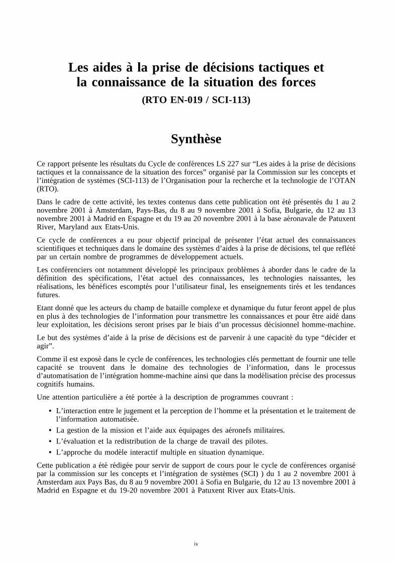
Cette publication a ete redigee pour servir de support de cours pour le cycle de conferences organisepar la commission sur les concepts et l’integration de systemes (SCI) ) du 1 au 2 novembre 2001 aAmsterdam aux Pays Bas, du 8 au 9 novembre 2001 a Sofia en Bulgarie, du 12 au 13 novembre 2001 aMadrid en Espagne et du 19-20 novembre 2001 a Patuxent River aux Etats-Unis.
iv

Contents
Page
Executive Summary iii
Synthese iv
List of Authors/Speakers vi
Reference
Introduction – Technical Overview and State of the Art 1by L. Crovella
Tactical Decision Making: The Interaction of Human Perception and Judgment with 2Automated Information Processing and Presentation – Situational Awareness andUnderstanding
by H.S. Marsh, P.W. Quinn, G.J. Toth and D.A. Jakubek
Tactical Decision Making: The Interaction of Human Perception and Judgment with 3Automated Information Processing and Presentation – Decision Support
by H.S. Marsh, P.W. Quinn, G.J. Toth and D.A. Jakubek
Mission Management and Crew Assistance for Military Aircraft – Cognitive Concepts and 4Prototype Evaluation
by A. Schulte
On-Board Decision Support through the Integration of Advanced Information Processing 5and Human Factors Techniques: The POWER Project
by H.H. Hesselink, G.D.R. Zon, F. Tempelman, J.W. Beetstra, A.M. Vollebregt andD.P. Hannessen
Future Trends and Developments 6by L. Crovella
v

List of Authors/SpeakersLecture Series Director: Dr. Ing. Luigi CROVELLA
Societa’ Italiana Avionica S.p.A.Strada Antica di Collegno 25310146 TorinoITALY
AUTHORS/LECTURERS
Dr.-Ing. Axel SCHULTE Mr. H.H. HESSELINKESG Elektroniksystem und Logistik Gmb H National Aerospace Laboratory, NLRDept. EF-E Anthony Fokkerweg 2P.O. Box 800569 1059 CM AmsterdamD-81605 Munich THE NETHERLANDSGERMANY
Dr. Howard S. MARSHOffice of Naval ResearchONR 311, BCT1 Room 607800 N. Quincy StreetArlington, VA 22217-5660UNITED STATES
CO-AUTHORS
Mr. Jelle W. BEETSTRA Mr. Daan P. HANNESSENNational Aerospace Laboratory National Aerospace LaboratoryAnthony Fokkerweg 2 Anthony Fokkerweg 21059 CM Amsterdam 1059 CM AmsterdamTHE NETHERLANDS THE NETHERLANDS
Mr. Frank TEMPELMAN Mr. Arjen M. VOLLEBREGTNational Aerospace Laboratory National Aerospace LaboratoryAnthony Fokkerweg 2 Anthony Fokkerweg 21059 CM Amsterdam 1059 CM AmsterdamTHE NETHERLANDS THE NETHERLANDS
Mr. G.D. Rolf ZON LCDR David A. JAKUBEKNational Aerospace Laboratory Office of Naval ResearchAnthony Fokkerweg 2 800 N. Quincy Street1059 CM Amsterdam Arlington, VA 22217-5660THE NETHERLANDS UNITED STATES
Mr. Paul W. QUINN Mr. Gary J. TOTHOffice of Naval Research Office of Naval Research800 N. Quincy Street 800 N. Quincy StreetArlington, VA 22217-5660 Arlington, VA 22217-5660UNITED STATES UNITED STATES
vi

1-1
Introduction – Technical Overview and State of the Art
Dr. Ing. Luigi CrovellaSocieta’ Italiana Avionica- SIA- S.p.A.
Strada antica di Collegno 25310146 Torino, [email protected]
Objective
Today the use of Decision Aids Systems for Commander and Operators in the Battlefield area isplaying an important role due to the new frequent situation of joint coalition and asymmeticwarfare in which Defense Forces are involved.On these occasions, the capability of own Forces to follow the evolution of the Tactical Situationin real time is extremely important.Since Combat Survival and Mission Accomplishment depend upon Operators performance in theprocess of decision-making, and the Operators performance depends upon the degree ofawareness, Situation Awareness can be seen as a result of a continuous assessment of situationparameters by the Operators.This Mission critical chain of sub-segment functions is greatly influenced by the nature of thetechnical systems the Operator is having to deal with.
The purpose of the present Lecture Series is to provide to the audience:• Definition of the problem• Overview of the state-of-the-art• Description of some research and development programs• Exposure to the end-users of the potential benefits of the decision aids employment• Future trends
What is Decision?
Decision, following the Webster’s Dictionary, means “the act or process of deciding”, andto decide means “to arrive at a solution that ends uncertainty”, as well as “to make a choice”.This definition is correct for our purpose.
What is a Decision Aid?
In today's information-intensive Battlefield, Operators need decision aids to free them frominformation overload.
Decision aiding technologies fuse data from onboard sensors and outside sources to:• Create a composite picture of the battlefield• Recognize potential threats• Impart key information to friend forces.• Instantaneously update mission plans.
Paper presented at the RTO SCI Lecture Series on “Tactical Decision Aids and Situational Awareness”, held in Amsterdam,The Netherlands, 1-2 November 2001; Sofia, Bulgaria, 8-9 November 2001; Madrid, Spain, 12-13 November 2001;
Maryland, United States, 19-20 November 2001, and published in RTO-EN-019.

1-2
Key Elements of Decision-Aiding Software are typically:• Data fusion - combines track information from a variety of sources into a single best
picture of the Battlefield• Situation assessment – continually monitors this dynamic picture for impacts to the plan• Mission planners – recommend updates to the plan• Execution aids - help the crew in executing the mission.
What is Tactical Decision Making?
In line with the above definition, tactical decision-making is the main task and responsibility ofthe tactical decision-maker, who is active at any level of the tactical decision-making process.Unfortunely, the decision has to be based upon tactical military information and operationalenvironment which are, by definition, always uncertain to varying degrees.Therefore effective tactical decision-making refers primarely to the ability to use logical andsound judgement to make decisions on available information.The available information is developing from the elementary external data collected by sensorsystems to the situational awareness through a judgement process.What above need to be supported by appropriate decision aids in order to improve operatorperformance.The automation of the process has to be coherent with the above.
What is Situational Awareness?
Situational awareness is generally defined as the degree of accuracy by which the Operator’sperception of the external environment reflects the reality.To our purpose, situational awareness is instead to be defined as “the ability to reliably,accurately and continuously collect information on the situation, enemy or friendly, when andwhere required”.In simple words, in the military environment “it is the mechanism which pinpoints targets andthreats to represent the Battlespace situation”.It is always to be reminded that, in line with the basic definition, awareness is a matter of degreeand not an absolute.
Situation Awareness
Situation awareness is the major element of the information superiority which is needed for theBattlespace dominance by the Systems of Systems, in accordance with the updated Defenserequirements.
Information Superiority
Information superiority is the result of the capability to gather, process, integrate, disseminateand display situation awareness information, together with a corresponding increase in theability to use that information.This ability is the knowledge of the Battlespace, which is necessary to make decisions and takeactions allowing to dominate the Battlespace.A very careful attention has to be put in obtaining the knowledge, so that it is coherent with thecognitive processes.

1-3
Only if this is reached, the decision-making is optimized and the man-machine loop is closedaccording to the requirements.
Automation aspects
Automation is a fundamental issue to achieve an improved operational effectiveness of thedecision-making process.This is due to the large amounts of data to be handled in dynamic and heavy scenario, whichcould overwelm Operators capabilities.The fundamental problem encountered during the implementation of an effective automation ishow support is provided by decision aid on elements of the decision-making.The dualism is to use the decision aid as a prosthesis adding additional capabilities to theOperators or simply as a tool available to the Operators; the differences are related to the role ofthe aid in the decision process.The prosthetic approach is targeted to replace the Operators when the situation causes anexcessive workload that cannot be managed by the human capabilities and to provide the neededdecision outcomes.The tool approach is targeted to assist the Operators active role in accordance with the decision-making process requirements.These approaches are not mutually exclusive but complementary, depending on situation context,the specific nature of the decision aid element and the Operators role.The correct choice is let to the designers capability and experience.
Lecture Series Overview
The present Lecture Series concentrates on the discussion of examples of applications covering inparticular:
• Interaction of human perception and judgement with automated information processingand presentation
• Mission Management and Crew assistance• Approach to cognitive and cooperative Operators assistance in the field of Tactical Flight
Mission Management• On-board decision support techniques• Pilot oriented workload evaluation and redistribution• Multiple hypotheses multiple model approach techniques
The goal is that the detailed presentations together with the discussions of achievements,problems and lessons learned from the Programs shall help Decision Aids Systems potentialdesigners and users in defining and evaluating operational requirements and affordable solutions.
An extensive use of the modern design and development processes and techniques based on theSystems Engineering, Systems Analysis, Functional Analysis, Simulation and Rapid Prototypinghave to be considered for the success of the Programs.

This page has been deliberately left blank
Page intentionnellement blanche

2-1
Tactical Decision Making:The Interaction of Human Perception and Judgment with Automated
Information Processing and Presentation
I. Situational Awareness and Understanding
Dr. Howard S. Marsh, Mr. Paul W. Quinn,Mr. Gary J. Toth, LCDR David A. Jakubek
Office of Naval Research800 N. Quincy Street
Arlington, VA 22217-5660, USA
Tactical decisions are made under conditions best described as “the fog and friction of war”. They tend to bejudgmental rather than analytical and are based on the decision maker’s perception of the situation and of hisor her options for meeting objectives defined by the commander. The perception and the resulting decisionsare very sensitive to the quality and completeness of the knowledge that the decision maker obtains throughinteractions with the decision support systems.
Modern information technology provides enormous potential for expanded situational awareness using avariety of information management, display, and human-system interaction tools that can help the decisionmakers penetrate the “fog of war” and deal with the “friction of war”. On the other hand, the increased use ofautomation also tends to remove the decision makers from direct observation of the situation and requires themto rely on information that is derived or inferred by processes that are embedded within a complex system ofsystems. This can impede the judgmental decision process due to lack of confidence in the information or dueto a desire to obtain more information before committing to a course of action. The relationship between thehuman judgmental processes and the automated decision support systems is particularly important for tacticalcombat direction and execution, where the pressure to decide and act is intense and where the results ofdecisions are often lethal.
This lecture explores the process in which the decision maker achieves an awareness and understanding of thesituation based on observations and on his or her model* of the world and of the current operational context.
*A model of the world is simply a set of rules and relationships that describe how entities and events occur and movethrough time and space. For example, our world model tells us that entities that move through the air are either birds oraircraft and that automobiles do not move through the air. A model of the context is a similar set of rules andrelationships that describe how the elements of the world model are related to the current operational situation. Forexample, if our context is open ocean operations, our context model tells us that entities moving along the surface of theearth are most likely ships and not trains or automobiles. Similarly, if the context is peace, then our context model tells usthat incoming aircraft are not likely to be attacking us.
Paper presented at the RTO SCI Lecture Series on “Tactical Decision Aids and Situational Awareness”, held in Amsterdam,The Netherlands, 1-2 November 2001; Sofia, Bulgaria, 8-9 November 2001; Madrid, Spain, 12-13 November 2001;
Maryland, United States, 19-20 November 2001, and published in RTO-EN-019.

2-2
A Traditional Model for Decision Making
Decis ionExperience
Context
Unders tandingKnowledge
Information
Real World
Perception
Data
Figure 1. A Traditional Model for Decision Making
This is the first part of a two-part lecture dealing with situational awareness and tactical decision aids and therole of information technology in supporting the operational processes.
Figure 1 above shows a traditional model for moving from observed data to a perception of the situation andthen to a decision on how to respond. This first lecture examines the cognitive process that leads to perceptionand understanding of the situation and the way that technology is used to support that process. The secondlecture examines the further processes for reaching a decision to act upon that understanding of the situation.
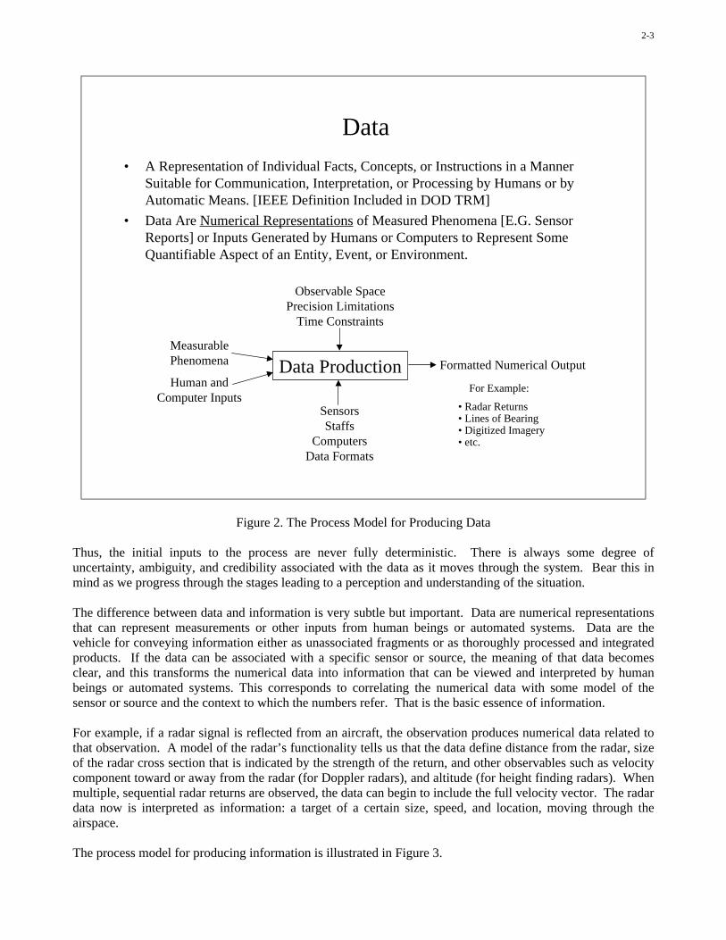
The first step in the process that leads to a decision is observation of the real world through all availablemeasurements, human inputs, and encyclopedic information stored in computers and in documents. Thesebasic fragments of information are then expressed as digital representations called data so that they can bemoved and managed easily. This is shown in Figure 2.
A very important factor is introduced at the time when we make a measurement and express it as data. Themeasurement itself is an observation of some phenomenon or multiple phenomena associated with a specificevent or entity. The event or entity is fully deterministic, it is a specific and precise element in the overall stateof the environment. However, the act of observing phenomena associated with that entity or event producesdata that contains some element of statistical uncertainty. Even a human observation of an event or entity is aprobabilistic determination of the state of the environment. The probability, or confidence level, of theobservation may be very high, but we still need to recognize that the resulting data do not represent “groundtruth”.
2-3
Data
• A Representation of Individual Facts, Concepts, or Instructions in a MannerSuitable for Communication, Interpretation, or Processing by Humans or byAutomatic Means. [IEEE Definition Included in DOD TRM]
• Data Are Numerical Representations of Measured Phenomena [E.G. SensorReports] or Inputs Generated by Humans or Computers to Represent SomeQuantifiable Aspect of an Entity, Event, or Environment.
Data ProductionMeasurablePhenomena
Human andComputer Inputs
SensorsStaffs
ComputersData Formats
Observable SpacePrecision Limitations
Time Constraints
Formatted Numerical Output
For Example:
• Radar Returns• Lines of Bearing• Digitized Imagery• etc.
Figure 2. The Process Model for Producing Data
Thus, the initial inputs to the process are never fully deterministic. There is always some degree ofuncertainty, ambiguity, and credibility associated with the data as it moves through the system. Bear this inmind as we progress through the stages leading to a perception and understanding of the situation.
The difference between data and information is very subtle but important. Data are numerical representationsthat can represent measurements or other inputs from human beings or automated systems. Data are thevehicle for conveying information either as unassociated fragments or as thoroughly processed and integratedproducts. If the data can be associated with a specific sensor or source, the meaning of that data becomesclear, and this transforms the numerical data into information that can be viewed and interpreted by humanbeings or automated systems. This corresponds to correlating the numerical data with some model of thesensor or source and the context to which the numbers refer. That is the basic essence of information.
For example, if a radar signal is reflected from an aircraft, the observation produces numerical data related tothat observation. A model of the radar’s functionality tells us that the data define distance from the radar, sizeof the radar cross section that is indicated by the strength of the return, and other observables such as velocitycomponent toward or away from the radar (for Doppler radars), and altitude (for height finding radars). Whenmultiple, sequential radar returns are observed, the data can begin to include the full velocity vector. The radardata now is interpreted as information: a target of a certain size, speed, and location, moving through theairspace.
The process model for producing information is illustrated in Figure 3.

2-4
Information• The Refinement of Data Through Known Conventions and Context for
Purposes of Imparting Knowledge. [DOD TRM]• Information Is Produced When Data Is Expressed Within a Context That Gives
It Meaning in Terms of the Nature of the Observed or Inferred Entity, Event,or Environmental Feature, Including Criteria Associated With the ProducingSystem Such As Precision and Confidence Level.
– Contextual or Semantic Interpretation– Combination of Individual Data Associated With a Common Entity, Event, or
Environmental State (e.g. multiple lines of bearing or multiple radar hits)
InformationProduction
Numerical Data
Physical World ModelCurrent Context Model
Multimedia Representations
Ambiguities and UnknownsLimits on PrecisionTime Constraints
Multimedia Information For Example:
• Vehicle PLI• Aircraft PLI• Ship PLI• RF Emissions• etc.
Figure 3. The Process Model for Producing Information
The next step in the process from observing to understanding is to convert the information to knowledge of thesituation. This is the process that generates a perception of the situation.
Knowledge is produced when information is correlated with a model of the world and the current context.Consider the example of the radar return. If the information indicates an entity at an altitude of 10,000 feetand a speed of 500 nautical miles per hour, the “world model” tells us that it is most likely a fixed wingaircraft, and most likely a turbojet powered aircraft.
As more information is correlated with this radar return, we may know even more about it. For example, IFFreturns may indicate that it is a friendly military aircraft, or other types of information may indicate that it is ahostile military aircraft. Each of these additional pieces of information can be correlated with one another,according to the current operational context.
Knowledge often builds from multiple possible interpretations, called multiple hypotheses. As we gather moreinformation, we decide which of these interpretations to believe, and this produces our perception of thesituation. We also recognize where additional information is needed, and this produces a directed search foradditional information.
This process is illustrated in Figure 4.

2-5
Building Knowledge from Information:Perception of the Situation
World Model
Information Based onObservations
Correlation
Multiple Alternatives(Hypotheses) Regarding
the Current Situation
Interpretationof the Observed
Information
Tailoring of Model
Directed Search for Information
Knowledgeand
Assumptions
Current ContextRelevant Model
Perception
Observations
Figure 4. Building Knowledge and a Perception of the Situation
The production of knowledge from information is just one more step in correlating observations with ourmodels of the world and the operational context. The principal factor introduced at this point in the process isthe need to infer knowledge based on an interpretation of information and patterns of information within theframework of the models of the world and the context. This is where the human cognitive processes becomeimportant and where the partnership between the machines and the humans begins to become complex.
Inference and interpretation are based to a great extent on the credibility assigned to information. This isespecially true when we have multiple hypotheses to consider and when the information and the world modeland context model do not align perfectly with one another. Sometimes we can identify a key piece ofinformation that will clearly differentiate among the hypotheses, but more often we can only develop ourperception with an imperfect degree of confidence.
Any imprecision, ambiguity, or uncertainty in the source data will carry through the process and lead tocorresponding imperfections in our knowledge and our perception of the situation. This theme, dealing withuncertainties and ambiguities, is one that lies at the heart of the decision support automation that we strive toperfect. Figure 5 shows a process model for producing knowledge.

2-6
Knowledge• Knowledge Is the Interpretation of Information Concerning Entities, Events,
and Environmental States That Results in a Specific Conclusion About thePhysical World Based on the Available Information and Current Context.
• Knowledge Is the “As Is” Perception of the Current Situation Based on aContextual Interpretation and Integration of Available Information.
• Knowledge Can Be Derived From Recognition of Patterns of InformationWithin the Current Semantic and Contextual Frames of Reference
– Correlation of Observables: E.G. HULTEC– Correlation of Observed Entities: E.G. Aggregation of Units to Organizations– Interpretation Based on Physical Constraints: E.G. Inference of Entity Type
Production ofKnowledge
MultimediaInformation
Current Context• Order of Battle• Technical Intel.• IPB• etc.
Information GapsAmbiguities
Time Constraints
Context ModelsRecognizable PatternsTime-distance ModelsTrafficability Models
etc.
Perception of the Situation
For Example:
• HULTEC• Force Deployments• etc.
Figure 5. The Process Model for Producing Knowledge
We now introduce the notion of a “perception map” as shown in the diagram in Figure 6. We draw inferencesfrom this base of knowledge, assumptions, and recognized uncertainties using judgment and experience.Human beings are very adept at correlating current patterns of information with past experience, especiallywhen information is displayed as visual patterns that can be compared with previous experiences.
The perception map is a useful tool in understanding why we reach certain conclusions, why we are sometimessurprised by outcomes that are different from what we expected, and how we cope with uncertainties. Ingeneral, we strive to move from the “known unknown” sector to the “known” sector, to decrease the degree ofuncertainty.
We make assumptions when we cannot resolve “known unknowns” that are essential to the perception. Inthose cases, we rely on judgment, experience, and intuition to define the assumption. The danger here is thatwe may forget that we based our perception on a critical assumption rather than a “known” set of information.We may also forget that a “known” set of information was actually based on imperfect data, as noted earlier.Consequently, even those things that we “know” are known only to some degree of confidence.

2-7
The Perception Map
KNOWN ASSUMED
KNOWNUNKNOWNS
UNKNOWNUNKNOWNS
SURPRISES
JUDGMENTEXPERIENCE
INTUITION
Figure 6. A Simple “Perception Map”
The “perception map” shows some essential features of the perception that leads to our understanding of thesituation. The main factor is the inherently statistical nature of all the underlying information. We can knowthe situation only as well as we can make observations and interpret them. If observations are in error, we willhave error in perceiving the situation. If models of the world or the operational context are in error, we willinfer incorrect knowledge from the information. The previous example of inferring that an approachingaircraft is not attacking was based on an operational context of peace. A disastrous error in perception occurswhen we think we are at peace but the adversary has actually made a transition to war and is launching asurprise attack.
While the “assumptions”, the “known unknowns”, and the imperfect “knowns” are certainly problems to bemanaged, the real villains in the perception map are the “unknown unknowns”. Ideally, our information andour models of the world and context are good enough for us to identify all the critical “unknowns” and movethem from the “unknown unknown” sector to the “known unknown” sector. Automated information systemscan be powerful tools to help us do this, since they can track vast amounts of information and continuallycorrelate and update relationships of information with world models and context models.
As noted in Figure 7, the mere fact that we know something does not mean that we understand what thatknowledge means. We may know too little about a situation to make sense of it; we may be confronted with“facts” that appear to contradict one another and that tend to confuse us; or we may know too much and bedistracted by interesting knowledge at the expense of focusing on the really important knowledge.

2-8
Understanding Is the Basis for the Decision
“I Don’t Understand Everything I Know.”
• This Statement Provides the Best Insight Into the Difference BetweenKnowledge and Understanding
• Information Systems Need to Help the Decision-Maker Understand theSituation, Not Just Know It
– Situation Awareness Is Not the Objective
– Situation Understanding Is Our Goal
• If I Know Too Much, It May Impede My Understanding of the CriticalInformation -- Information Overload, “Glare of War”
• If I Know Too Little, My Predisposition to Assume Things MayDistort My Perception of Reality
– Experts Have Greater Predisposition to Assume Than Novices
– The Judgment and Wisdom That Comes With Expertise Also BringsIntellectual “Baggage”
Figure 7. The Difference Between Knowledge and Understanding
Another factor in reaching an understanding of a situation is the tendency of human beings to approachunderstanding from a predisposition to assume something about the situation even before any information ispresented. Prejudgment is a fact that we need to recognize. When we have little information and littleknowledge of the situation, most of our perception lies in the “assumed” and “known unknown” sectors. Our“knowledge” or awareness of the situation is driven by the assumptions and the recognition of gaps inknowledge. This can tend to cause our prejudgment to dominate.
The process for moving from knowledge to understanding relies very heavily on the judgment and experienceof the human being and on his or her ability to correlate past experiences, training, and education with thecurrent context.
Constraints on understanding the situation include gaps in knowledge, preconceived notions of what thesituation should be, and time pressures. The fog and friction of war are clearly at play at this point.
Since judgment is a major factor in understanding the situation, the inputs to the process certainly includecredibility factors related to the information that has been presented. Here we probably find a “feedback loop”back to the process that converted information to knowledge. If we think that we know something but cannotunderstand it, we will try to “rethink” the process from observed information to interpretation in terms ofknowledge or perception of the situation. This is the typical question: “What’s wrong with this picture?”
Figure 8 illustrates a process model for developing understanding from knowledge of the situation.

2-9
Understanding• Understanding Is the Interpretation of Knowledge in Terms of Meaning
Within the Current Operational Context.– Recognition of the Meaning of Recognized Patterns in the Perceived Situation– Interpretation of the “As Is” Knowledge in Terms of the Dynamics of the Situation– Identification of Uncertainties, Ambiguities, and Needs for More Information– Identification of Requirements to Respond to the Situation
• Understanding Applies Judgment to Interpret Knowledge in Terms of PastExperience, Training, and Other Factors That Allow Patterns to Be AssociatedWith Both the Static and Dynamic Aspects of the Observed Situation.
Building anUnderstanding
Perception• Recognized Patterns• Evolving Patterns
Intelligence
Expectations
Credibility Factors JudgmentExperience
Context
PreconceptionsKnowledge Limitations
Time Constraints
Understanding of the Situation
For Example:
• Imminent Attack• Enemy Center of Mass• etc.
Figure 8. The Process Model for Building Understanding
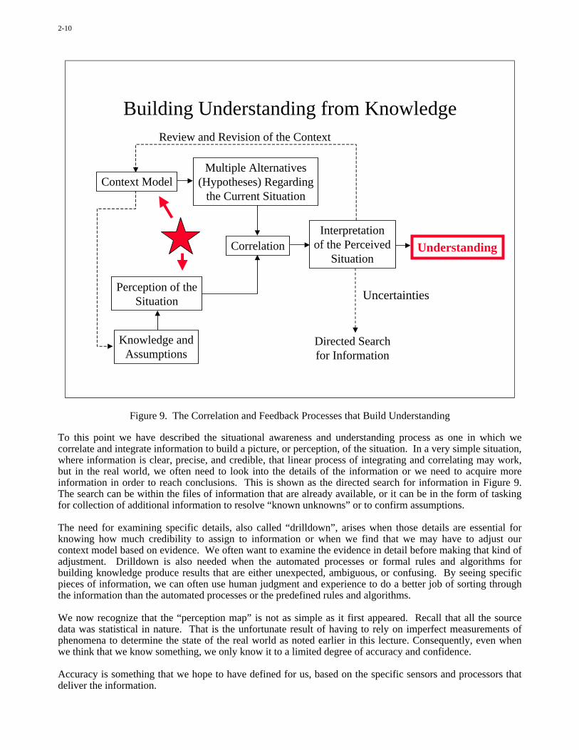
Understanding is achieved through a correlation of the perception with the likely alternatives (multiplehypotheses) of what that perception means in terms of the current operational context. That correlation is thenreviewed in terms of the context to produce an understanding of what it means. Note that the context modelplays an important role in moving from information to knowledge (perception) and then to understanding. Wecontinually “fine tune” our view of the information by matching our judgments, conclusions, and assumptionswith the context model. That model itself grows and becomes more precise and specific as we use the processto update the model. As we know more about the situation, we adjust the context model, and we use thatadjusted model to make further progress toward understanding. This is illustrated in Figure 9.
We also can fool ourselves by making errors in assuming or adjusting a context model based upon conclusionsthat were reached by using the context model itself. If we believe strongly enough that a certain situationexists, we may find evidence to reinforce that belief even when it is false. In engineering parlance, if we buildan amplifier with enough gain and with fine enough tuning, we will see the signal we seek even if it is notthere; we will have produced an oscillator instead of an amplifier. A basic tenet in deception tactics is to showsomething that is false but that is expected, thereby reinforcing a predisposition to reach wrong conclusionsabout the situation.
2-10
Building Understanding from KnowledgeReview and Revision of the Context
Correlation
Multiple Alternatives(Hypotheses) Regarding
the Current Situation
Directed Searchfor Information
Understanding
Perception of theSituation
Knowledge andAssumptions
Context Model
Uncertainties
Interpretationof the Perceived
Situation
Figure 9. The Correlation and Feedback Processes that Build Understanding
To this point we have described the situational awareness and understanding process as one in which wecorrelate and integrate information to build a picture, or perception, of the situation. In a very simple situation,where information is clear, precise, and credible, that linear process of integrating and correlating may work,but in the real world, we often need to look into the details of the information or we need to acquire moreinformation in order to reach conclusions. This is shown as the directed search for information in Figure 9.The search can be within the files of information that are already available, or it can be in the form of taskingfor collection of additional information to resolve “known unknowns” or to confirm assumptions.
The need for examining specific details, also called “drilldown”, arises when those details are essential forknowing how much credibility to assign to information or when we find that we may have to adjust ourcontext model based on evidence. We often want to examine the evidence in detail before making that kind ofadjustment. Drilldown is also needed when the automated processes or formal rules and algorithms forbuilding knowledge produce results that are either unexpected, ambiguous, or confusing. By seeing specificpieces of information, we can often use human judgment and experience to do a better job of sorting throughthe information than the automated processes or the predefined rules and algorithms.
We now recognize that the “perception map” is not as simple as it first appeared. Recall that all the sourcedata was statistical in nature. That is the unfortunate result of having to rely on imperfect measurements ofphenomena to determine the state of the real world as noted earlier in this lecture. Consequently, even whenwe think that we know something, we only know it to a limited degree of accuracy and confidence.
Accuracy is something that we hope to have defined for us, based on the specific sensors and processors thatdeliver the information.

2-11
Perception is Based Upon IncompleteInformation of Variable Quality and Credibility
KNOWN ASSUMED
KNOWNUNKNOWNS
UNKNOWNUNKNOWNSLow
Medium
High
CO
NFI
DEN
CE
CONFIDENCE
IMPO
RTANCE
Low
Medium
High Low
Medium
High
Figure 10. The “Perception Map” With Additional Details Related to Confidence and Importance
Confidence and importance are often difficult to determine and may be influenced by many factors, includingthe “strength” of the observed phenomenon, the experience of human beings who may have interpreted theobservations, alternative hypotheses associated with the observations, known unknowns, and so forth.
The diagram in Figure 10 is not intended to be a precise description of how confidence and importance affectthe interaction among known, assumed, and unknown aspects of the perception. It is only a notional diagramto help display how those factors affect our overall knowledge and understanding of the situation.
Understanding of a situation is, in many respects, like putting together the pieces of a puzzle. When we haveall the pieces, when the fully assembled picture is one that is simple, and when each piece has parts of thatpicture that define where it fits, we can construct the full picture. However, when some pieces are missing orwhen we find pieces from other puzzles that look similar to one another (alternate hypotheses), we havedifficulty constructing the picture. This is the challenge in understanding a complex situation with numerousalternative interpretations and with information that is statistical in nature and that has many missing pieces.
When confronted with such a challenge, we need to search for the information that is most critical to makingthe judgment and eliminating the unlikely alternative interpretations. This is called “value of information”.We look for the missing pieces that will have the greatest influence on our determination rather than for lessinfluential ones. We also look among the ambiguous pieces of information for the ones that make the greatestdifference in our conclusions. This process of “diagnosing” the situation is identical to the process that aphysician uses to diagnose a disease. This is illustrated in Figure 11.

2-12
Mathematical Rigor for Dealing WithRelationships Among Uncertain Information
Observation ACondition α
Condition β
Condition γ
Condition δ
Observation B Observation C
Observation D Observation E
[A,α]
[B,C]
[β,D,C,E]
[β,D]
Condition ε
Observation F
[C,D]
Condition φ
[E,F,γ,ε]
Figure 11. A Bayesian Network Formalism for Understanding a Set of Observations
As previously noted, the “diagnosis” of the situation rests on key elements of information and on relationshipsamong them. Those relationships can be expressed as a network of nodes and links that show way thatobserved information can be traced to specific inferences about conditions or states of the observed system thatcan be made from the observations.
In this example, condition φ at the lower right hand corner of the network is distinguished from conditionδ only by observation F. All other observations are consistent with both of them, even though the likelihoodof the two “hypotheses” (i.e. condition φ or condition δ) may be different based on those observations.Furthermore, if condition δ does exist, then we can infer that conditions α,β, and γ also exist, since condition δdepends on observations that imply those other conditions too.
The question of likelihood is important in making the diagnosis. Bayesian nets allow the appearance of anobservation or condition to be expressed in terms other than 100% or 0%. We can then produce a diagnosisthat gives probability estimates for each conclusion based on the probabilities assigned to the sourceinformation. In the example of the radar return from an aircraft, the probabilities might be expressed as: (fixedwing 100%), (friendly 80%, hostile 5%, unknown 15%), (attacking 2%, not attacking 90%, unknown 8%).
The diagnostic net in Figure 11 showed that observation F was the most important piece of information todistinguish between conditions δ and φ. Therefore, if we need to make that distinction, we need to try toobserve F.
2-13
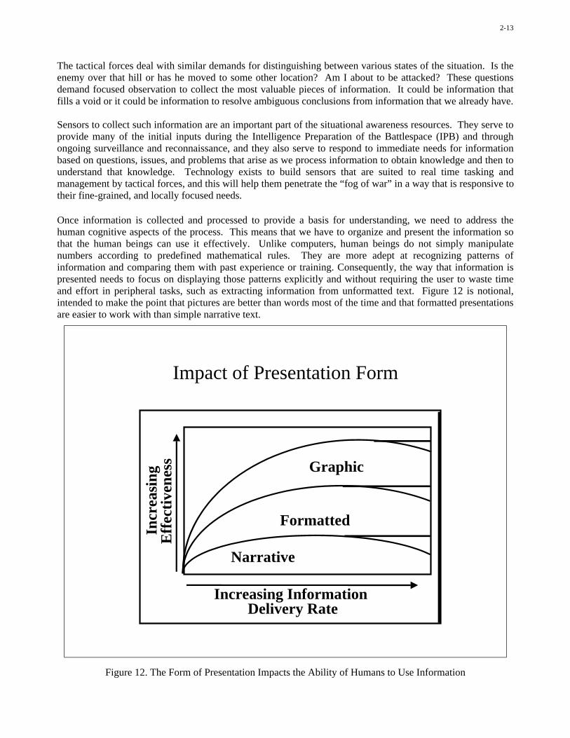
The tactical forces deal with similar demands for distinguishing between various states of the situation. Is theenemy over that hill or has he moved to some other location? Am I about to be attacked? These questionsdemand focused observation to collect the most valuable pieces of information. It could be information thatfills a void or it could be information to resolve ambiguous conclusions from information that we already have.
Sensors to collect such information are an important part of the situational awareness resources. They serve toprovide many of the initial inputs during the Intelligence Preparation of the Battlespace (IPB) and throughongoing surveillance and reconnaissance, and they also serve to respond to immediate needs for informationbased on questions, issues, and problems that arise as we process information to obtain knowledge and then tounderstand that knowledge. Technology exists to build sensors that are suited to real time tasking andmanagement by tactical forces, and this will help them penetrate the “fog of war” in a way that is responsive totheir fine-grained, and locally focused needs.
Once information is collected and processed to provide a basis for understanding, we need to address thehuman cognitive aspects of the process. This means that we have to organize and present the information sothat the human beings can use it effectively. Unlike computers, human beings do not simply manipulatenumbers according to predefined mathematical rules. They are more adept at recognizing patterns ofinformation and comparing them with past experience or training. Consequently, the way that information ispresented needs to focus on displaying those patterns explicitly and without requiring the user to waste timeand effort in peripheral tasks, such as extracting information from unformatted text. Figure 12 is notional,intended to make the point that pictures are better than words most of the time and that formatted presentationsare easier to work with than simple narrative text.
Impact of Presentation Form
Incr
easi
ng
Eff
ecti
vene
ss
Increasing Information Delivery Rate
Narrative
Formatted
Graphic
Figure 12. The Form of Presentation Impacts the Ability of Humans to Use Information
2-14
Modern command and control systems are built with these facts in mind. Most information is presented assome form of graphic display: a map, a bar chart, and so forth. This provides the overarching view andpattern; it establishes context and a framework for interpreting information; and it guides the users to areaswhere they may want to “drill down” to see more information. The next level, as they drill down, is often abrief, formatted display of amplifying data. Then, if they need more, they often can retrieve textualinformation or source data. The principle is first to present the overview, often general and qualitative, and tolet the users determine how much they need in terms of actual numerical data or textual references.
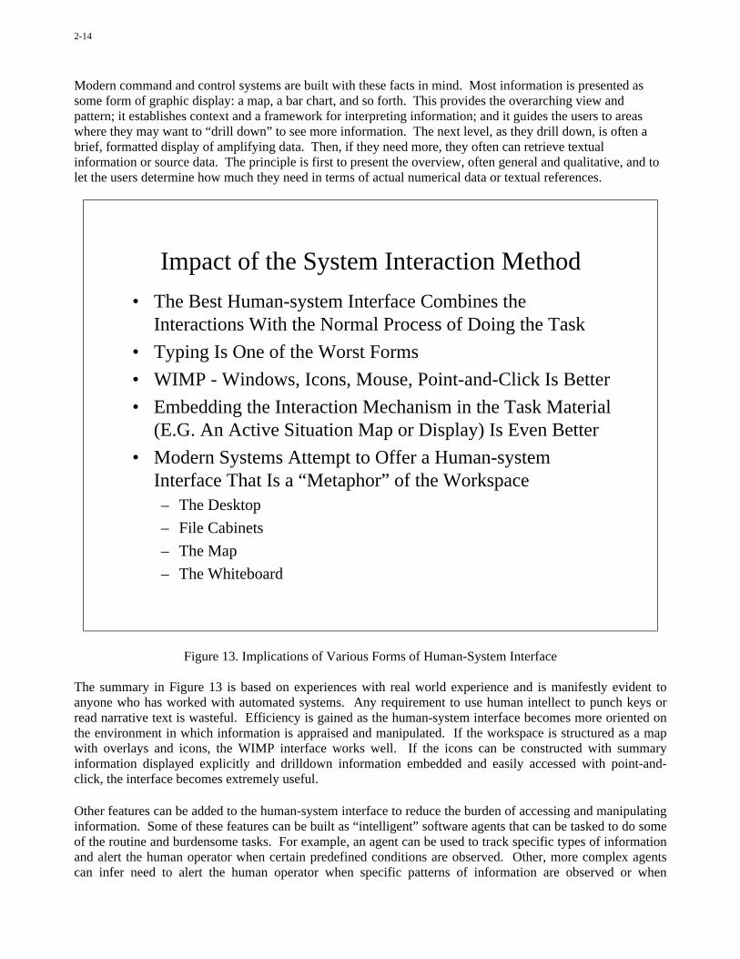
Impact of the System Interaction Method
• The Best Human-system Interface Combines theInteractions With the Normal Process of Doing the Task
• Typing Is One of the Worst Forms
• WIMP - Windows, Icons, Mouse, Point-and-Click Is Better
• Embedding the Interaction Mechanism in the Task Material(E.G. An Active Situation Map or Display) Is Even Better
• Modern Systems Attempt to Offer a Human-systemInterface That Is a “Metaphor” of the Workspace– The Desktop
– File Cabinets
– The Map
– The Whiteboard
Figure 13. Implications of Various Forms of Human-System Interface
The summary in Figure 13 is based on experiences with real world experience and is manifestly evident toanyone who has worked with automated systems. Any requirement to use human intellect to punch keys orread narrative text is wasteful. Efficiency is gained as the human-system interface becomes more oriented onthe environment in which information is appraised and manipulated. If the workspace is structured as a mapwith overlays and icons, the WIMP interface works well. If the icons can be constructed with summaryinformation displayed explicitly and drilldown information embedded and easily accessed with point-and-click, the interface becomes extremely useful.
Other features can be added to the human-system interface to reduce the burden of accessing and manipulatinginformation. Some of these features can be built as “intelligent” software agents that can be tasked to do someof the routine and burdensome tasks. For example, an agent can be used to track specific types of informationand alert the human operator when certain predefined conditions are observed. Other, more complex agentscan infer need to alert the human operator when specific patterns of information are observed or when
2-15
ambiguities and contradictions are observed. Speech interface is also a feature of some new systems, currentlyin the commercial world but making their way into military command and control systems. We can expectsignificant advances that begin to provide actual human-computer dialog and multi-agent cooperative tasking.
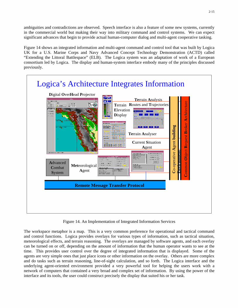
Figure 14 shows an integrated information and multi-agent command and control tool that was built by LogicaUK for a U.S. Marine Corps and Navy Advanced Concept Technology Demonstration (ACTD) called“Extending the Littoral Battlespace” (ELB). The Logica system was an adaptation of work of a Europeanconsortium led by Logica. The display and human-system interface embody many of the principles discussedpreviously.
Logica’s Architecture Integrates Information
Terrain Analysis Routes and Trajectories
Co-
oper
ativ
e A
gent
bui
ldin
gE
nvir
onm
ent
Remote Message Transfer Protocol
Terrain Elevation Display
Current Situation Agent
Terrain Analyser
Meteorological Agent
Com
mon
Obj
ect R
eque
st B
roke
r A
rchi
tect
ure
Digital OverHead Projector
AdvancedCombatSystem
Figure 14. An Implementation of Integrated Information Services
The workspace metaphor is a map. This is a very common preference for operational and tactical commandand control functions. Logica provides overlays for various types of information, such as tactical situation,meteorological effects, and terrain reasoning. The overlays are managed by software agents, and each overlaycan be turned on or off, depending on the amount of information that the human operator wants to see at thetime. This provides user control over the degree of integrated information that is displayed. Some of theagents are very simple ones that just place icons or other information on the overlay. Others are more complexand do tasks such as terrain reasoning, line-of-sight calculation, and so forth. The Logica interface and theunderlying agent-oriented environment provided a very powerful tool for helping the users work with anetwork of computers that contained a very broad and complex set of information. By using the power of theinterface and its tools, the user could construct precisely the display that suited his or her task.

2-16
TDBM Drill-Down
Figure 15. A Representative Display of Tactical Situation Data
The Office of Naval Research is managing a program called Dominant Battlespace Command (DBC). It isbeing executed by Concurrent Technologies Corporation, with the objective to build visualizationenvironments that interface with currently available command and control information systems to improve acommander’s ability to comprehend the battlespace situation and make decisions quickly and effectively.
This DBC display shown in Figure 15 is connected to the track data base management (TDBM) software in theGlobal Command and Control System (GCCS). The interface allows the users to see both the overall tacticalsituation and selected details (drilldown) of specific information for each entity in the track data base. Thistype of drilldown capability is a standard feature in GCCS and many other command and control systems thatare currently in use. It is an important way to present the overall pattern without saturating the user with toomuch detail, and still allow the user to obtain those details when needed.
The map display is really a “rich meta data” display rather than a display of actual data. It is like a merger ofthe “index” and “annotated outline” of the content in the data base. It provides an overall sense of the situationand the relationships among entities and events that have been observed. When we need the actual data, itprovides pointers to the selected information.
Users of the track display may want to see specific entities and not others. This is especially important whenthe display is cluttered with objects that are not of immediate interest. Filters provide a capability to select thetypes of entities that are shown and the ones that are maintained in the background. This is another importantcapability provided by systems such as GCCS.
2-17
When we use filters to declutter a display, we need to be careful to assure that the hidden entities are called toour attention if necessary. Otherwise, we can reach conclusions about the overall situation and take actionsthat may be in conflict with the actual state of the battlespace. This can cause unintentional “blue on blue” or“blue on white” engagements or dangerous conflicts of fires and maneuver. This is where software agents canbe established to monitor the hidden entities and alert the users when certain criteria are met.
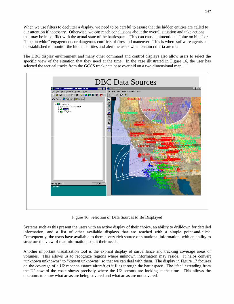
The DBC display environment and many other command and control displays also allow users to select thespecific view of the situation that they need at the time. In the case illustrated in Figure 16, the user hasselected the tactical tracks from the GCCS track data base overlaid on a two dimensional map.
DBC Data Sources
Figure 16. Selection of Data Sources to Be Displayed
Systems such as this present the users with an active display of their choice, an ability to drilldown for detailedinformation, and a list of other available displays that are reached with a simple point-and-click.Consequently, the users have available to them a very rich source of situational information, with an ability tostructure the view of that information to suit their needs.
Another important visualization tool is the explicit display of surveillance and tracking coverage areas orvolumes. This allows us to recognize regions where unknown information may reside. It helps convert“unknown unknowns” to “known unknowns” so that we can deal with them. The display in Figure 17 focuseson the coverage of a U2 reconnaissance aircraft as it flies through the battlespace. The “fan” extending fromthe U2 toward the coast shows precisely where the U2 sensors are looking at the time. This allows theoperators to know what areas are being covered and what areas are not covered.

2-18
U2
Figure 17. Visualization of the Sensor Coverage of a U2 Surveillance Aircraft
The information in this display can also be presented as a three dimensional perspective display if that suits theusers. Other options for the presentation include a true 3-D display or an immersive reality environment. TheDBC program is experimenting with all of these types of user interfaces to determine how each one couldcontribute to situation awareness and understanding for different types of tasks and operational situations.
We conclude the first part of the two-part lecture with the summary in Figure 18.
Situational awareness must always contend with “fog of war”. As we are able to observe, process, anddisseminate more information about the battlespace, some of the fog will be removed, but we can never seetrue “ground truth”. Uncertainties and ambiguities will always remain and must be tracked and managed. Infact, as we bring more sensors to bear and connect more users with one another, the potential for ambiguitiesand contradictions increases. We see this in some of the current tactical data link systems where the number ofunresolved duplications of track and target data increases as we add more sensors. Consequently, we havegreater need for automated tools and models to resolve ambiguities and contradictions.
The second problem area that we need to address is what can be called the “glare of war”. This is theoverabundance of information that is delivered to the users and that can obscure the information that theyactually need. The fact that information will now come in many different forms and at different ratescompounds the problem of presenting an integrated, coherent, and relatively simple picture to the humanbeings so that they can recognize the important patterns and not be distracted by irrelevant information. Weneed to make sure that additional information helps their performance.

2-19
Information-Leveraged Warfare Presents NewChallenges as Well as Opportunities
• The “Fog of War”: A Continuing Challenge– Uncertainty: Let’s Not Fool Ourselves - We Are Not Omniscient!– Ambiguity: More Information May Increase Ambiguity– Assumptions: Forever Necessary to Fill Critical Information Gaps– Unknown Unknowns
• The “Glare of War”: The New Challenge– Massive Inputs of Information– Mix of Relevant and Marginally Useful Information– Heterogeneous Forms of Information and Presentation– Hiding of Important Information Within the “Clutter”
Too Much Information Can Be As Bad As Too Little.The Key Is In The Management And Presentation.
Figure 18. Summary: Challenges and Opportunities in Information-Leveraged Warfare

This page has been deliberately left blank
Page intentionnellement blanche

3-1
Tactical Decision Making:The Interaction of Human Perception and Judgment with Automated
Information Processing and Presentation
II. Decision Support
Dr. Howard S. Marsh, Mr. Paul W. Quinn,Mr. Gary J. Toth, LCDR David A. Jakubek
Office of Naval Research800 N. Quincy Street
Arlington, VA 22217-5660, USA
Modern information technology can improve situational awareness and understanding far beyond thetraditional “fog of war”, but these improvements are useful only if the operators can apply that awareness andunderstanding to reach decisions better and faster than before. The goal is to achieve “decision superiority”not just information superiority.
In the complex and fast-paced battlespace of the future, humans will rely more and more on informationtechnology to deliver knowledge and to assist them in using that knowledge. As the range, speed, lethality,and cost of weapons increase, the human cognitive processes will have to be augmented by rapid, automatedappraisal of the situation and the available courses of action. The decisions will have to be reached by a mixof human and machine reasoning, including a theater-wide perspective as well as a local perspective. Thispresents new challenges for the system developers and the operational concept developers, and thosechallenges are being addressed in a number of development and experimentation programs.
This discussion extends the prior consideration of situational awareness and understanding to address the useof that awareness and understanding to determine the decision.
Paper presented at the RTO SCI Lecture Series on “Tactical Decision Aids and Situational Awareness”, held in Amsterdam,The Netherlands, 1-2 November 2001; Sofia, Bulgaria, 8-9 November 2001; Madrid, Spain, 12-13 November 2001;
Maryland, United States, 19-20 November 2001, and published in RTO-EN-019.

3-2
Three Types of Decision Drivers
• Procedure– Decisions That Are Made According to a Schedule
– Examples: the Daily Briefing to the Boss, the ATO, Ordering Lunch
• Need– Event-driven
– A Decision Must Be Made to Respond to the Event
– Examples: Destroy Incoming Missile, Steer Car Around Pothole
• Opportunity– Event-driven
– If a Decision Can Be Made Quickly Enough, Some UnanticipatedGain May Result
– Example: Enemy CP Sighted, One-day Price Reduction
Figure 1. Reasons for Making Decisions
We make decisions for one of three reasons as indicated in Figure 1.
An important goal of modern knowledge superiority or decision superiority is to allow us to move fromprocedural decision making toward opportunistic decision making. This allows us to dominate the battlespaceand to take the initiative away from our adversary. We still need to be able to respond to events beyond ourcontrol, but we strive to minimize this type of reactive posture and move as much as possible toward aproactive posture.
Procedural decision making, on the other hand, is largely decoupled from the real time battle and is not wellsuited to a dynamic battlespace.
How can we take advantage of improved situational awareness and understanding to achieve effectivecapability for both proactive and reactive decision making and to move away from the rigid process-drivendecisions? That question is the focus of this part of the two-part lecture.
As a first step, let us look at the role that information plays in the decision process. We take it on faith thatmore information is good, and less is bad, but that may not really be true. If additional information causes acluttered or confused view of the situation, then we are better off without it. We need the “right” information,not just all available information. This is indicated in Figure 2. The main point to bear in mind is that theinformation is presented to the user for only one purpose: to assist in understanding the situation andresponding to it. Modern command and control information systems are focused on that objective and includea blend of technology and human factors that support the cognitive process leading to decisions.
3-3
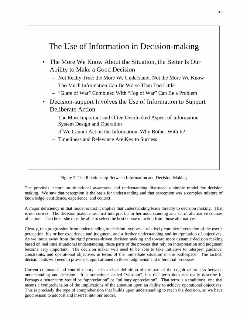
The Use of Information in Decision-making
• The More We Know About the Situation, the Better Is OurAbility to Make a Good Decision– Not Really True: the More We Understand, Not the More We Know
– Too Much Information Can Be Worse Than Too Little
– “Glare of War” Combined With “Fog of War” Can Be a Problem
• Decision-support Involves the Use of Information to SupportDeliberate Action– The Most Important and Often Overlooked Aspect of Information
System Design and Operation
– If We Cannot Act on the Information, Why Bother With It?
– Timeliness and Relevance Are Key to Success
Figure 2. The Relationship Between Information and Decision-Making
The previous lecture on situational awareness and understanding discussed a simple model for decisionmaking. We saw that perception is the basis for understanding and that perception was a complex mixture ofknowledge, confidence, experience, and context.
A major deficiency in that model is that it implies that understanding leads directly to decision making. Thatis not correct. The decision maker must first interpret his or her understanding as a set of alternative coursesof action. Then he or she must be able to select the best course of action from those alternatives.
Clearly, this progression from understanding to decision involves a relatively complex interaction of the user’sperception, his or her experience and judgment, and a further understanding and interpretation of objectives.As we move away from the rigid process-driven decision making and toward more dynamic decision makingbased on real time situational understanding, those parts of the process that rely on interpretation and judgmentbecome very important. The decision maker will need to be able to take initiative to interpret guidance,constraints, and operational objectives in terms of the immediate situation in the battlespace. The tacticaldecision aids will need to provide support attuned to those judgmental and inferential processes.
Current command and control theory lacks a clear definition of the part of the cognitive process betweenunderstanding and decision. It is sometimes called “wisdom”, but that term does not really describe it.Perhaps a better term would be “appreciation” or “military appreciation”. That term is a traditional one thatmeans a comprehension of the implications of the situation upon an ability to achieve operational objectives.This is precisely the type of comprehension that builds upon understanding to reach the decision, so we havegood reason to adopt it and insert it into our model.
3-4
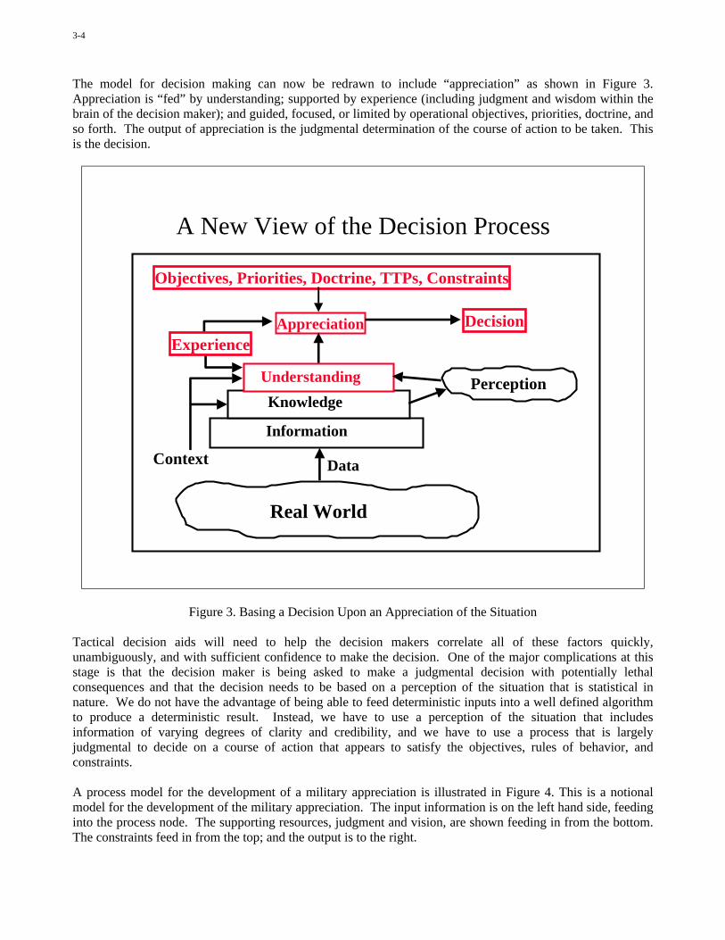
The model for decision making can now be redrawn to include “appreciation” as shown in Figure 3.Appreciation is “fed” by understanding; supported by experience (including judgment and wisdom within thebrain of the decision maker); and guided, focused, or limited by operational objectives, priorities, doctrine, andso forth. The output of appreciation is the judgmental determination of the course of action to be taken. Thisis the decision.
A New View of the Decision Process
Decision
Context
Understanding
Knowledge
Information
Real World
Perception
Appreciation
Objectives, Priorities, Doctrine, TTPs, Constraints
Data
Experience
Figure 3. Basing a Decision Upon an Appreciation of the Situation
Tactical decision aids will need to help the decision makers correlate all of these factors quickly,unambiguously, and with sufficient confidence to make the decision. One of the major complications at thisstage is that the decision maker is being asked to make a judgmental decision with potentially lethalconsequences and that the decision needs to be based on a perception of the situation that is statistical innature. We do not have the advantage of being able to feed deterministic inputs into a well defined algorithmto produce a deterministic result. Instead, we have to use a perception of the situation that includesinformation of varying degrees of clarity and credibility, and we have to use a process that is largelyjudgmental to decide on a course of action that appears to satisfy the objectives, rules of behavior, andconstraints.
A process model for the development of a military appreciation is illustrated in Figure 4. This is a notionalmodel for the development of the military appreciation. The input information is on the left hand side, feedinginto the process node. The supporting resources, judgment and vision, are shown feeding in from the bottom.The constraints feed in from the top; and the output is to the right.

3-5
Appreciation• Appreciation Is the Recognition of What the Situation Means in Terms of the
Response Needed to Achieve Objectives.• The Military Appreciation Is the Translation of Situation Understanding to
Decision Criteria That Include Full Consideration of Commander’s Intent,Doctrine, Rules of Engagement, Physical and Environmental Factors, Tactics,Techniques, and Procedures, Sustainment Capabilities, Enemy Capabilitiesand Intents, and All Other Factors That Influence the Course of Action.
• The Military Appreciation Relies on Judgment and “Wisdom” Based on theFull Set of Education and Experience of the Decision Makers.
Developing the Military Appreciation
Understanding ofThe Situation
Objectives andCommander’s Intent
Doctrine, ROE,TTPs, Etc.
Environmentaland Physical Factors
Decision
JudgmentWisdom
PrioritiesSustainment Factors
Time ConstraintsEtc.
For Example:
•Move•Strike•etc.Intelligence on Enemy
Capabilities and Intents
Figure 4. A Process Model for Developing the Military Appreciation
The current state of the art in information technology can do quite a bit to help decision makers appreciate thesituation, but true “artificial intelligence” remains in the realm of science fiction. Computers are very good atadding, subtracting, and comparing numbers, and they can execute processes with mathematical precision, butthey do not think. If the decision making is of a form conducive to algorithmic computation, such asdevelopment of a fire control solution, computers are far better than people. If the decision making requiresjudgmental inferences and tradeoff in a complex situation, the human beings probably outperform thecomputers. Such is the case with most tactical decision support systems. The human being is the decisionmaker, and the computer is the support tool. Sometimes it can actually recommend a course of action anddevelop an initial draft of the plan, and at other times it simply does the bookkeeping and arithmetic.
Collaboration among human beings is often required when the appreciation requires different sets ofexperiences and skills. For example, an air strike on a ground target may require judgment on weaponseffects, threats, weather, and so forth. In those cases, collaboration among experienced people is needed. Thiscan be either in a single physical location or distributed across a network. Modern technology gives us theability to construct such distributed virtual staffs and to have opportunity to use expertise from the finest mindsavailable rather than just the collocated staff.

3-6
Modern Information Technology Can SupportDistributed Virtual Staffs
Figure 5. A Collaborative Map Display With Overlays Managed by Multiple Users
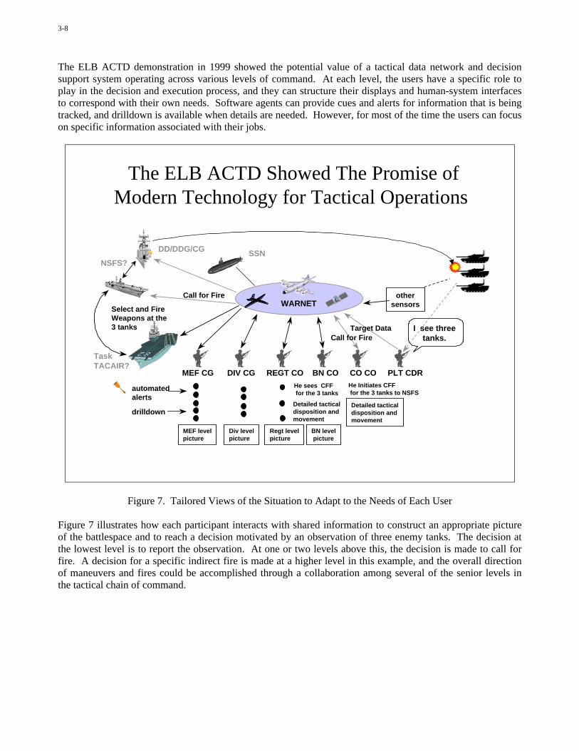
Figure 5 illustrates a form of distributed collaboration that was used during the “Extending the LittoralBattlespace” Advanced Concept Technology Demonstration (ELB ACTD) in 1999. The application was acommercial product called CU-SeeMe. It allowed users at various locations to draw on a shared overlaysuperimposed on a map of the battlespace. The application was hosted in standard desktop and laptop PCs,connected with one another through the ELB Wide Area Relay Network (WARNET). In this way, the users atdifferent locations could work together in real time to develop the maneuver plan. This is called “synchronouscollaboration” because all the users are collaborating with one another at the same time.
Another form of distributed collaboration is called “asynchronous collaboration”. In this case, each usercontributes to the product independently, either by placing products on a shared electronic table or bulletinboard, or by e-mail or some other means of information transfer. When we use e-mail to coordinate drafts of apaper or briefing, this is asynchronous collaboration.
Distributed collaboration during the ELB ACTD demonstration in 1999 included tactical warfighters in avariety of environments, not just people at consoles in command posts or on ships. Figure 6 shows a few ofthe environments during that demonstration. The command center was onboard the USS Coronado, at sea offthe coast of San Diego, California. The furthest reach for the airborne relay network (the WARNET) extendedto hand held computers and mobile equipment in HMMWVs in Yuma, Arizona. Synchronous collaborationusing CU-SeeMe, video and voice over Internet Protocol, and a commercial “chat room” application wassupported and allowed distributed tactical decision making based on a shared view of the situation.

3-7
The Distributed Collaboration Can ExtendDown to the Tactical Level
Figure 6. Locations of Warfighters During the Distributed Collaboration in the ELB ACTD Demonstration
This type of capability will become more important in the future, as we encounter situations in whichcommander’s intent, priorities, and rules of engagement will have to be interpreted and adapted to the situationin near real time. A full appreciation of the situation will demand an ability to consult with others in the chainof command or in adjacent commands so that all aspects of the alternative courses of action can be considered.Tactical decision aids will need to include capability for this type of distributed collaboration and consultation.They will have to be truly “network centric”.
We also need to remember that knowledge and understanding of the situation required an ability to presentinformation in a way that aligned it with the current operational context and integrated it to form recognizablepatterns and relationships. The same is true for appreciation. We need to present the information in a mannerthat allows the user to view objectives, alternative courses of action, and potential enemy actions within theframework of the current situation.
The tactical decision support system needs to help users who are likely to be under considerable stress at thetime. A human-system interface or a display that demands too much attention or that is intolerant of input-output errors will not be useful. A presentation that requires the user to integrate and correlate in his or hermind will be less useful than one which presents a clear and comprehensive picture of the important aspects ofthe situation and the implications of alternative actions.
The presentation should also allow the users to concentrate on the job at hand without having to keep track ofuncertainties that are being managed. Automated assistance (software agents) can reside in the background totrack those types of things and to cue or alert the user when necessary.
3-8
The ELB ACTD demonstration in 1999 showed the potential value of a tactical data network and decisionsupport system operating across various levels of command. At each level, the users have a specific role toplay in the decision and execution process, and they can structure their displays and human-system interfacesto correspond with their own needs. Software agents can provide cues and alerts for information that is beingtracked, and drilldown is available when details are needed. However, for most of the time the users can focuson specific information associated with their jobs.
The ELB ACTD Showed The Promise ofModern Technology for Tactical Operations
MEF CG DIV CG REGT CO BN CO CO CO PLT CDR
Call for Fire
He Initiates CFF for the 3 tanks to NSFS
Detailed tacticaldisposition andmovement
He sees CFF for the 3 tanks
Detailed tacticaldisposition andmovement
BN level picture
Regt levelpicture
Div levelpicture
MEF levelpicture
automatedalerts
othersensors
drilldown
Target Data
Select and FireWeapons at the3 tanks
Call for Fire
I see threetanks.
WARNET
DD/DDG/CG
NSFS?
TaskTACAIR?
SSN
Figure 7. Tailored Views of the Situation to Adapt to the Needs of Each User
Figure 7 illustrates how each participant interacts with shared information to construct an appropriate pictureof the battlespace and to reach a decision motivated by an observation of three enemy tanks. The decision atthe lowest level is to report the observation. At one or two levels above this, the decision is made to call forfire. A decision for a specific indirect fire is made at a higher level in this example, and the overall directionof maneuvers and fires could be accomplished through a collaboration among several of the senior levels inthe tactical chain of command.

3-9
Integrating the View of Situation, Objectivesand Constraints Helps to Support the Decision
Logica’s DOHP Overlay on a US Marine Corps C2PC Situation Displayto Show NoGo Lines and Excluded Areas
Figure 8. Integration of Other Decision Factors With Observed Situation Information
An appreciation of the situation and of the alternative courses of action is supported by displays that show howthe constraints map onto the battlespace. Those constraints can be trafficability affected by the weather orterrain, or they could be due to rules of engagement or some other factors.
Figure 8 is a screen-capture from the Logica UK system discussed in the first lecture. It shows how an overlayof maneuver constraints can be superimposed on the map used to plan movements. The overlay itself can be apredefined template or it can include some elements that are calculated, such as weather-related trafficabilityor inter-visibility demands for covert movement. The Logica system provided software agents to constructand manage these overlays and provided the users with appreciation of where they could move.
The tactical decision aid can also advise users of potential courses of action for both themselves and enemyforces. The overlay shown in Figure 9 was provided in the Logica system to show where units of various sizescould maneuver. The software agent that Logica used was based on a standard algorithm for maneuveringrobots in spaces with obstructions. Logica adapted this algorithm to provide reasoning for militaryorganizations moving through the hilly terrain at Camp Pendleton, California. We see the go, no-go areas ofthe prior overlay, and we see the allowable maneuver corridors added to the overlay.
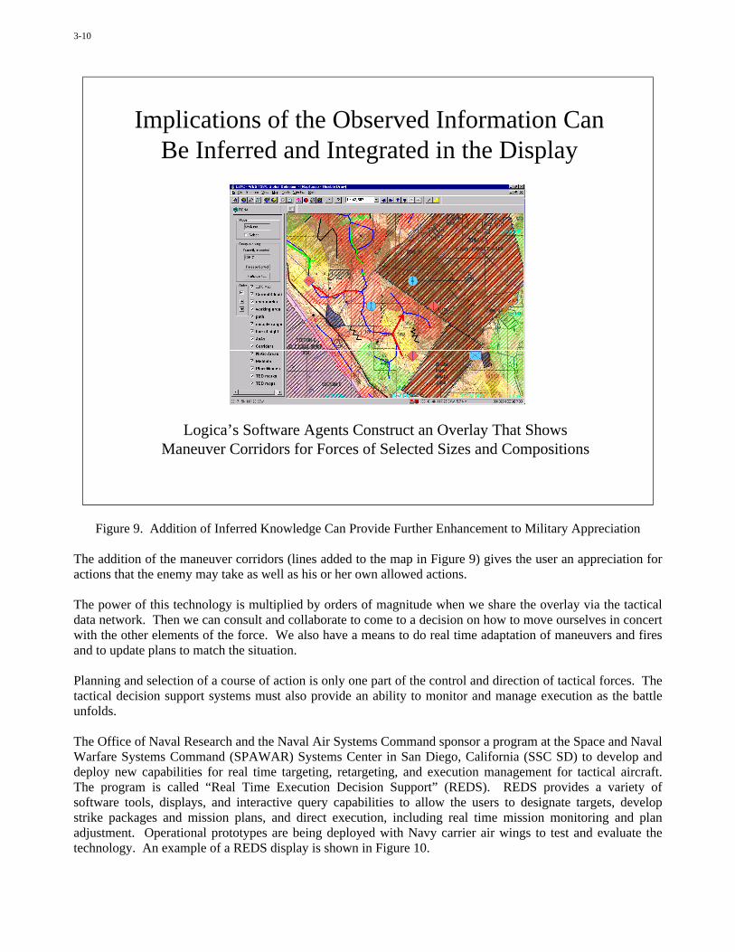
3-10
Implications of the Observed Information CanBe Inferred and Integrated in the Display
Logica’s Software Agents Construct an Overlay That ShowsManeuver Corridors for Forces of Selected Sizes and Compositions
Figure 9. Addition of Inferred Knowledge Can Provide Further Enhancement to Military Appreciation
The addition of the maneuver corridors (lines added to the map in Figure 9) gives the user an appreciation foractions that the enemy may take as well as his or her own allowed actions.
The power of this technology is multiplied by orders of magnitude when we share the overlay via the tacticaldata network. Then we can consult and collaborate to come to a decision on how to move ourselves in concertwith the other elements of the force. We also have a means to do real time adaptation of maneuvers and firesand to update plans to match the situation.
Planning and selection of a course of action is only one part of the control and direction of tactical forces. Thetactical decision support systems must also provide an ability to monitor and manage execution as the battleunfolds.
The Office of Naval Research and the Naval Air Systems Command sponsor a program at the Space and NavalWarfare Systems Command (SPAWAR) Systems Center in San Diego, California (SSC SD) to develop anddeploy new capabilities for real time targeting, retargeting, and execution management for tactical aircraft.The program is called “Real Time Execution Decision Support” (REDS). REDS provides a variety ofsoftware tools, displays, and interactive query capabilities to allow the users to designate targets, developstrike packages and mission plans, and direct execution, including real time mission monitoring and planadjustment. Operational prototypes are being deployed with Navy carrier air wings to test and evaluate thetechnology. An example of a REDS display is shown in Figure 10.

3-11
REDS Tactical Decision Aid
Figure 10. Decision Support for Real Time Planning, Replanning, and Monitoring of Execution
The REDS tactical decision aid provides a view of the battlespace that shows both friendly and threatcapabilities related to the tactical air missions. These include radar coverage, missile envelopes, targets, andother features that the users need to plan missions and reach conclusions on best alternatives for engaging timecritical targets in high threat environments. With such a tool, the mission planners can designate ingress andegress routes to avoid threats and can determine requirements for defense suppression, electronic warfare, andother support to the mission.
A need for tactical decision support does not end when the mission is planned, assigned, and launched. Abilityto monitor progress and to adapt to unplanned contingencies is also needed.
The technique used in REDS is shown in Figure 11. It provides a display of the plan in terms of the desiredsequence of actions and the specific times at which they occur. Those are the horizontal bars in the display.Each bar represents activities that are supposed to occur at specific times. The vertical line in the display is anindication of current time. It moves across the chart from left to right as time progresses. As it passes throughthe horizontal bars, they are assigned colors, from red to green, depending on whether the planned status atthat time has actually been achieved.
This type of display is a very user-friendly, intuitive way for the tactical decision makers to view the entire setof missions and to identify where they are on-track or in trouble. This gives a very clear and quickcomprehension, or appreciation, of the evolving situation with respect to the specific user’s functional areas ofresponsibility.
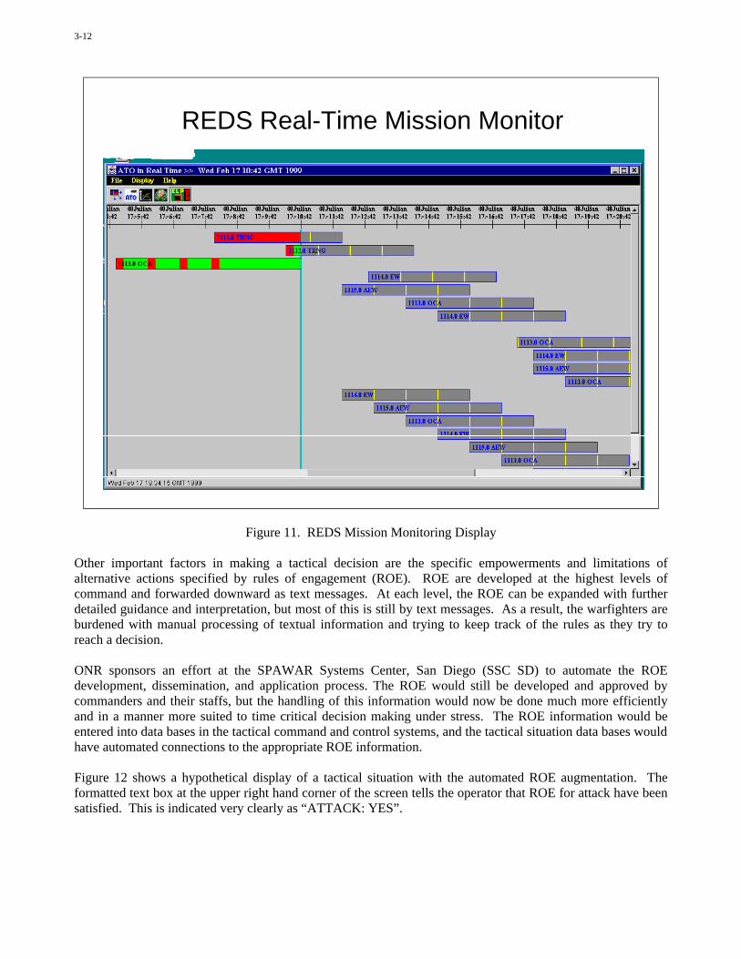
3-12
REDS Real-Time Mission Monitor
Figure 11. REDS Mission Monitoring Display
Other important factors in making a tactical decision are the specific empowerments and limitations ofalternative actions specified by rules of engagement (ROE). ROE are developed at the highest levels ofcommand and forwarded downward as text messages. At each level, the ROE can be expanded with furtherdetailed guidance and interpretation, but most of this is still by text messages. As a result, the warfighters areburdened with manual processing of textual information and trying to keep track of the rules as they try toreach a decision.
ONR sponsors an effort at the SPAWAR Systems Center, San Diego (SSC SD) to automate the ROEdevelopment, dissemination, and application process. The ROE would still be developed and approved bycommanders and their staffs, but the handling of this information would now be done much more efficientlyand in a manner more suited to time critical decision making under stress. The ROE information would beentered into data bases in the tactical command and control systems, and the tactical situation data bases wouldhave automated connections to the appropriate ROE information.
Figure 12 shows a hypothetical display of a tactical situation with the automated ROE augmentation. Theformatted text box at the upper right hand corner of the screen tells the operator that ROE for attack have beensatisfied. This is indicated very clearly as “ATTACK: YES”.
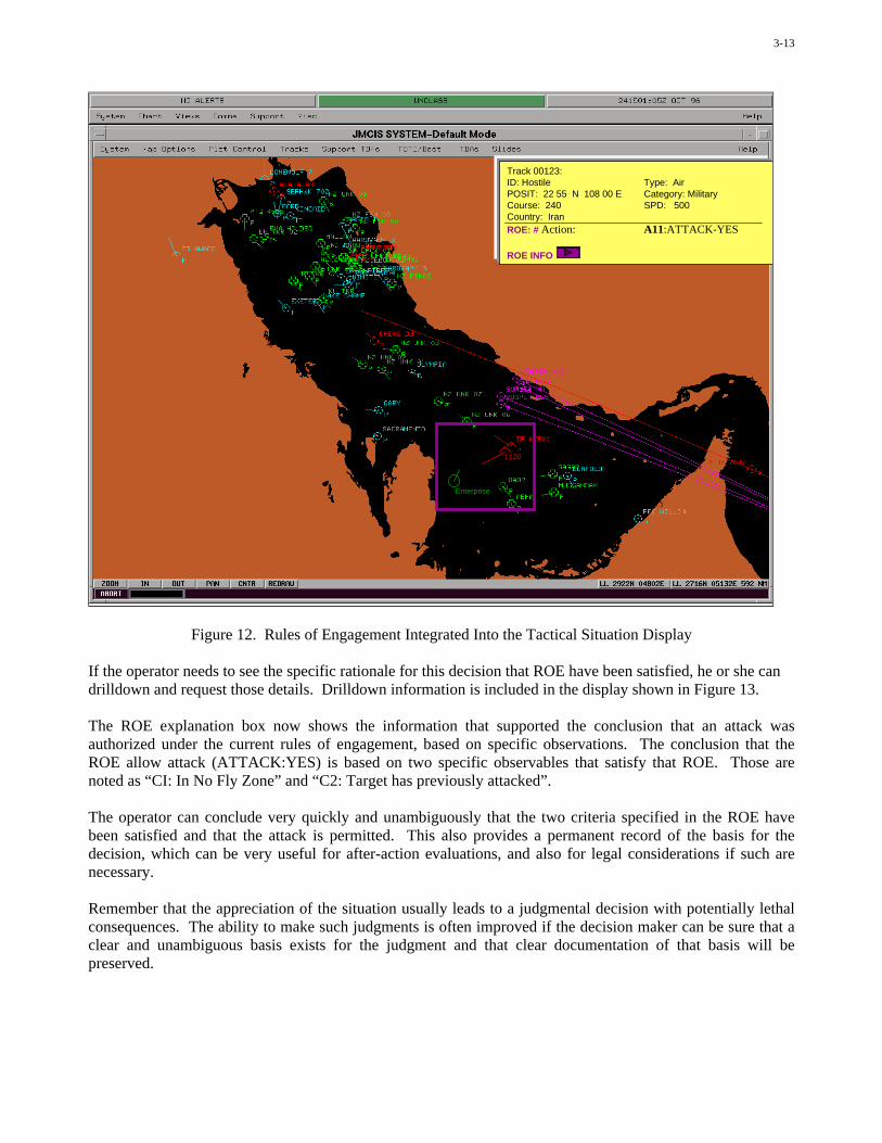
3-13
Enterprise
1120
Track 00123:ID: Hostile Type: AirPOSIT: 22 55 N 108 00 E Category: MilitaryCourse: 240 SPD: 500Country: IranROE: # Action: A11:ATTACK-YES
ROE INFO
Figure 12. Rules of Engagement Integrated Into the Tactical Situation Display
If the operator needs to see the specific rationale for this decision that ROE have been satisfied, he or she candrilldown and request those details. Drilldown information is included in the display shown in Figure 13.
The ROE explanation box now shows the information that supported the conclusion that an attack wasauthorized under the current rules of engagement, based on specific observations. The conclusion that theROE allow attack (ATTACK:YES) is based on two specific observables that satisfy that ROE. Those arenoted as “CI: In No Fly Zone” and “C2: Target has previously attacked”.
The operator can conclude very quickly and unambiguously that the two criteria specified in the ROE havebeen satisfied and that the attack is permitted. This also provides a permanent record of the basis for thedecision, which can be very useful for after-action evaluations, and also for legal considerations if such arenecessary.
Remember that the appreciation of the situation usually leads to a judgmental decision with potentially lethalconsequences. The ability to make such judgments is often improved if the decision maker can be sure that aclear and unambiguous basis exists for the judgment and that clear documentation of that basis will bepreserved.

3-14
Track 00123:ID: UNK Type: AirPOSIT: 22 55 N 108 00 E Category: MilitaryCourse: 240 SPD: 500Country: IranROE AmplifierA11:ATTACK-YES C1: In No Fly Zone
C2: Target has previously attacked
ROE ReferenceROE message generator
Enterprise
1120
Figure 13. ROE Display With Additional Drilldown Details
Advanced information technologies such as those discussed here will cause major changes in command andcontrol systems and processes. One of these changes is a shift from fully manual processes to a reliance onautomation to support the human beings, and even toward fully automated processes.
Automation is most important for tactical combat systems and weapon control systems, where complexity andtime demands make it difficult for human beings to be directly in the control loop. Even the act of flying anaircraft is sometimes beyond the capability of human beings. Modern tactical fighter and attack aircraft areoften highly unstable platforms. This allows them to have very fast response, but it also makes them verydifficult to fly by direct interaction of the pilot with flight control mechanisms. Consequently, a computer fliesthe aircraft, and the pilot exercises control of the computer, to provide specific objectives for it to meet. Thisis an example of a human-supervised automated process.
Tactical combat direction and command and control offer more opportunity for human beings to act within thedecision loop. Here the demands of time compression and complexity are still large, but the human beings areable to cope with them as long as the automated systems provide them with timely and “user friendly” support.Systems such as the Logica tactical decision aid, REDS, and automated ROE are examples of important effortsto provide such support to users who are embedded in the tactical decision processes.
Figure 14 shows the wide variety of human-computer relationships that occur in command and control systemsand processes.

3-15
The Relationship Between Humans andMachines Is Changing
• Manual Process– People Do the Work Using Pencil, Paper, Telephone, etc.
• Computer-Aided Manual Process– Humans Use the Technology to Do the Bookkeeping and the
Mathematics and to Move the Information Among Themselves
• Automated Process– Computers Run the Show
• Human-Supervised Automated Process– Computers Run the Show, but Humans Can Monitor and Intervene
Directly in the Process
• Human-in-the-Loop Process– The Human Is Inserted As a “Functional Module” Within the
Automated Process
• “Mixed Initiative” Process– The Human and the Computer Do Interconnected Tasks
Figure 14. The Wide Spectrum of Human-Computer Relationships in Command and Control
Architecture, commonality, and interoperability are additional factors that need to be taken into account whenbuilding a command and control system. At the tactical level of command and control, we are oftenchallenged by competing demands. On the one hand, we want to make use of common systems to the greatestextent possible to reduce burdens of training, operation, and maintenance. It also allows us to reduce total costof ownership by using commercial-off-the-shelf (COTS) equipment rather than expensive, purpose-builtmilitary hardware and software. When requirements are not oriented on near real time control, generalpurpose systems are often appropriate.
Unfortunately, tactical systems can impose very stressing requirements for near real time response andsoftware trustworthiness that often demand purpose-built technology. We do not rely on a COTS personalcomputer and general purpose software to generate fire control solutions within a second or less; and we donot want that COTS computer and software guiding the weapon in flight. For these functions, we generallyembed purpose-built computing in the combat systems and weapon systems.
Tactical decision aids are at the unfortunate “seam” between technology based on general purpose andpurpose-built computing. We will often find hybrid systems, where part of the process is based on COTS andpart is purpose-built for the military task. This could change as the performance and trustworthiness of COTSimproves, but we will have to live with the current situation until that time.
Figure 15 summarizes considerations of commonality versus purpose-built “stovepipe” systems.

3-16
An Important Architectural Issue:“Stovepipes” Versus Commonality
• A Trade-Off Between Objectives That Are OftenCompeting– Tailored, Optimized Performance (e.g. For Weapons Control)
• Real-Time• Strongly Focused on a Specific Function
– General Purpose, Common Systems and Applications• Economy of Scale for Procurement and O&M Support• Assured Interoperability
• One Size Does Not Necessarily Fit All– Administrative Functions– Strategic Command– Operational and Tactical Command– Tactical Control/Combat Direction– Combat Systems and Weapons Systems
Figure 15. Considerations in Building for Commonality or Purpose-Built Functionality
No discussion of situational awareness and tactical decision aids would be complete without some reference tointeroperability. This is especially true for coalition operations, where differences arise not only with thetechnologies but also with operational concepts, procedures, and language.
The first three “bullets” in Figure 16 are the interoperability areas that we are used to seeing. Once we achievethis level of interoperability, we can exchange data and process information. Our systems will work togetherat least to that extent.
The next two “bullets” address the parts of the process that enable knowledge, understanding, andappreciation. If we do not recognize semantic differences, we may misinterpret information and thereforemake an error perception. If our responses to information are not common, we may make decisions thatconflict with other decisions in the coalition force.
These last two “bullets” are the real challenge in coalition warfare. We know how to achieve interoperabilityup to the application level, and we even have some capabilities up to the semantic level, but we lack thefundamental tools to achieve the higher levels. This is a major focus area for current science and technologyprograms.

3-17
A Word About Interoperability What Does It Really Mean?
• Technical Interoperability– The Hardware and Software Can Operate Together
• Transaction Interoperability– Information Can Be Exchanged and Processed– Protocols Are Consistent Across the Systems
• Application Interoperability– The Applications Can Exchange Information
• Semantic Interoperability– Language and Meaning Are Commonly Understood
• Response Interoperability– The Expected Responses to Information Are Understood by All– e.g. We’ve Heard the Joke About: “Secure the Building”
Figure 16. Interoperability
In summary, the movement toward “information-leveraged” warfare, whereby the warfighters achieve greatereffectiveness through better use of information, has both positive and negative aspects.
We saw in the first lecture that the “fog of war” may be penetrated to some degree, but it will still exist. Wealso saw that the technology that helped penetrate the “fog” presented us with potential overload, the “glare ofwar”.
In this second lecture we saw that a major challenge in modern warfare is to be able to respond very quickly tocomplex situations and to reach a military appreciation and a decision based on our appreciation of thesituation. This caused us to be concerned with making judgments based on imprecise information, where lackof credibility and confidence can be impediments to decision making. We saw that some form of“partnership” between the human beings and the technology will be required as we move more and moretoward the real time tactical functions or toward the massive data base environments of the higher leveloperational and strategic commands.
These challenges provide a rich context for current research and development for situational awareness andunderstanding and tactical decision aids.

This page has been deliberately left blank
Page intentionnellement blanche

complexity of automation
effe
ctiv
enes
s/s
afet
y
cognitiveautomation
conventionalautomation
toda
y's
situ
atio
n
Figure 1: Expected benefit of conventionaland cognitive automation
Mission Management and Crew Assistance for Military Aircraft– Cognitive Concepts and Prototype Evaluation –
Dr. Axel Schulte
ESG – Elektroniksystem- und Logistik-GmbHAdvanced Avioncs Systems
P.O. Box 80 05 69. 81605 Munich. GermanyE-mail: [email protected]
1 SUMMARYThis paper describes an approach to cognitive and co-operative operator assistance in the field of tactical flightmission management. A framework for a generic functional concept is derived from general considerations ofhuman performance and cognitive engineering. A system built according to these human-centred designprinciples will be able to keep up with the change of situation parameters, in order to provide situationaladapted operator assistance. Such a Cognitive Assistant System (e.g. Onken & Walsdorf, 2000) represents anapproach to ensure the highest degree possible of situation awareness of the flight deck crew as well as asatisfactory workload level.
This generic approach to mission management and crew assistance for military aircraft has been realised indifferent application domains such as military transport and air-to-ground attack. Even applications in thedomain of unmanned aerial vehicles (UAV) (Stütz et al., 2001) are in reach. This paper mainly covers twostate-of-the-art research and development activities: the Crew Assistant Military Aircraft (e.g. Schulte & Stütz,1998; Frey et al., 1999; Stütz & Schulte, 2000) is a functional prototype for the air transport application andthe Tactical Mission Management System (e.g. Schulte et al., 1999; Schulte et al., 2001/a&b) as anexperimental solution for air-to-ground attack aircraft. The paper gives details on the prototype developmentand the experimental evaluation.
2 INTRODUCTIONPerforming military combat missions in an uncertain dynamic tactical environment, presents a potentiallyintolerable workload for the crew. Therefore, several research and development activities are conducted inorder to automate flight crews’ tasks. Figure 1 illustrates the expected benefit of an increase of complexity ofconventional automation as opposed to a so-called cognitive automation approach (e.g. Onken & Walsdorf,2000; Putzer & Onken, 2001). Investigations of modern aircraft cockpits show that a further increase in use ofconventional automation will not necessary result in increased productivity. Automation itself became acomplex element within the already complex environment of the cockpit. In some cases conventionalautomation has even become the key-factor for decreasedsafety (e.g. due to ‘mode confusion’). (e.g. Wiener &Nagel, 1988) The reason for this seems to be found in theunpredictability of the machine’s behaviour due toinconsistencies between the machine function and thepilot’s mental model of it.
Consequently, Billings (1991 & 1997) stated his wellknown principles of human-centred automation i.e.:
• The pilot bears the responsibility for safety of flight.• Pilots must remain in command of their flights.
And as corollaries:• The pilot must be actively involved.• The pilot must be adequately informed.• The operator must be able to monitor the automation
assisting them.
4-1
Paper presented at the RTO SCI Lecture Series on “Tactical Decision Aids and Situational Awareness”, held in Amsterdam,The Netherlands, 1-2 November 2001; Sofia, Bulgaria, 8-9 November 2001; Madrid, Spain, 12-13 November 2001;
Maryland, United States, 19-20 November 2001, and published in RTO-EN-019.

• The automated systems must be therefore predictable.• The automated systems must also monitor the human operator.• Every intelligent system element must know the intent of other intelligent system elements.
These principles imply the co-operative approach, establishing the automation as a team player within theflight-deck crew. But, how can this practically be accomplished? Onken (1994) formulates his basicrequirements concerning human-machine interactions in combat aircraft as follows (cited from Onken &Walsdorf, 2000):
(1) It must be ensured the representation of the full picture of the flight situation, including that the attentionof the cockpit crew is guided towards the objectively most urgent task or sub-task as demanded in thatsituation.
(2) A situation with overcharge of the cockpit crew might come up even when situation awareness has beenachieved by the pilot crew. In this case the assistant system has to transfer the situation into a normal onewhich can be handled by the crew in a normal manner.
The basic requirement (1) addresses the system performance needed to most effectively ensure the pilots’situation awareness. The basic requirement (2) is formulated to avoid pilots’ overcharge, in particular as toplanning, decision-making, and plan execution tasks.
The actual automation functions required to provide intelligible interaction and efficient use of such acognitive assistant system are derived from a concept taking into consideration the process of humaninformation processing, the cognitive process (as described in the following chapter). The approach aims atthe provision of crew assistant functions which focus upon the interpretation and diagnosis of the situation andthe monitoring and if necessary the retrieval of the integrity of superior goals such as safety, combat survivaland mission accomplishment (Schulte & Stütz, 2000). In order to realise this approach, a way had to be foundhow to deal with human goal knowledge in machine systems. Today’s cockpit avionics completely neglectthis kind of information. Of course, the treatment of goals is implicit (e.g. GCAS is designed to avoid groundcollision per definition). But, goals, goal violations and the possible interference of different goal domains(e.g. combat survival vs. mission accomplishment) are not yet processed explicitly. In most cases conventionalautomation is used in more or less separated systems. Coupling of application domains (e.g. ground collisionand threat exposure) has to be performed by the human operator on his own. Cognitive systems promise theexploitation of synergetic resources within the co-operation of machine system and human operator. (SeeFigure 2.)
Strengths ofHuman-Being
Pattern Recognition
Problem Reduction
Ability to Learn
Ability of Abstraction
Problem Generalization
Creativity
Instinct
Long-Term Monitoring
Complex Planningand Decision-Making
Retrieval ofDetailed Information
Broadband Reception
Parallel Processing
Stress Resistance
Objectivity
Cooperation
Deliberative
Negotiative
CognitiveMan-MachineCooperation
Communication
Figure 2: Synergetic resources to be exploited through man-machine co-operation
The next chapter deals with the refinement of such a cognitive automation concept on the basis of theconsideration of the human knowledge processing scheme. A generic functional framework will be derived.The following chapter provides the results of two research and development programmes being based uponthese concepts.
4-2
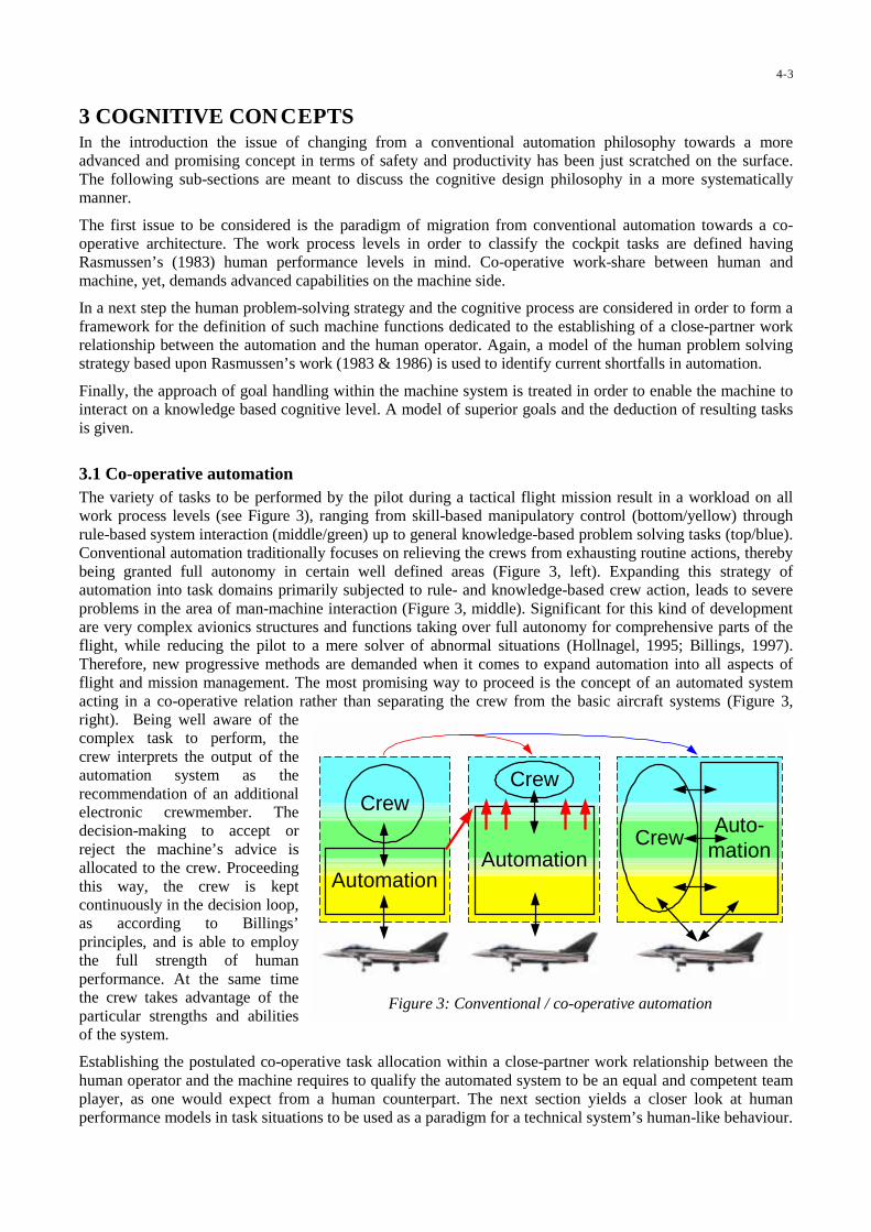
3 COGNITIVE CON CEPTSIn the introduction the issue of changing from a conventional automation philosophy towards a moreadvanced and promising concept in terms of safety and productivity has been just scratched on the surface.The following sub-sections are meant to discuss the cognitive design philosophy in a more systematicallymanner.
The first issue to be considered is the paradigm of migration from conventional automation towards a co-operative architecture. The work process levels in order to classify the cockpit tasks are defined havingRasmussen’s (1983) human performance levels in mind. Co-operative work-share between human andmachine, yet, demands advanced capabilities on the machine side.
In a next step the human problem-solving strategy and the cognitive process are considered in order to form aframework for the definition of such machine functions dedicated to the establishing of a close-partner workrelationship between the automation and the human operator. Again, a model of the human problem solvingstrategy based upon Rasmussen’s work (1983 & 1986) is used to identify current shortfalls in automation.
Finally, the approach of goal handling within the machine system is treated in order to enable the machine tointeract on a knowledge based cognitive level. A model of superior goals and the deduction of resulting tasksis given.
3.1 Co-operative automationThe variety of tasks to be performed by the pilot during a tactical flight mission result in a workload on allwork process levels (see Figure 3), ranging from skill-based manipulatory control (bottom/yellow) throughrule-based system interaction (middle/green) up to general knowledge-based problem solving tasks (top/blue).Conventional automation traditionally focuses on relieving the crews from exhausting routine actions, therebybeing granted full autonomy in certain well defined areas (Figure 3, left). Expanding this strategy ofautomation into task domains primarily subjected to rule- and knowledge-based crew action, leads to severeproblems in the area of man-machine interaction (Figure 3, middle). Significant for this kind of developmentare very complex avionics structures and functions taking over full autonomy for comprehensive parts of theflight, while reducing the pilot to a mere solver of abnormal situations (Hollnagel, 1995; Billings, 1997).Therefore, new progressive methods are demanded when it comes to expand automation into all aspects offlight and mission management. The most promising way to proceed is the concept of an automated systemacting in a co-operative relation rather than separating the crew from the basic aircraft systems (Figure 3,right). Being well aware of thecomplex task to perform, thecrew interprets the output of theautomation system as therecommendation of an additionalelectronic crewmember. Thedecision-making to accept orreject the machine’s advice isallocated to the crew. Proceedingthis way, the crew is keptcontinuously in the decision loop,as according to Billings’principles, and is able to employthe full strength of humanperformance. At the same timethe crew takes advantage of theparticular strengths and abilitiesof the system.
Establishing the postulated co-operative task allocation within a close-partner work relationship between thehuman operator and the machine requires to qualify the automated system to be an equal and competent teamplayer, as one would expect from a human counterpart. The next section yields a closer look at humanperformance models in task situations to be used as a paradigm for a technical system’s human-like behaviour.
Crew
AutomationAutomation
Crew
Auto-mation
Crew
Figure 3: Conventional / co-operative automation
4-3

3.2 Human problem-solving strategy and the cognitive processConsidering the automated functions within today’s cockpit avionics and flight guidance systems against thebackground of Rasmussen’s model of the human knowledge processing scheme (see Figure 4) shortcomingsin conventional automation design can be easily identified (Onken & Walsdorf, 2000). It covers only about thehalf of what has been considered the spectrum of human cognitive functions. This situation calls for action inthe fields of a profound situation recognition and identification as well as the goal-driven decision-making.This scope of duties is in compliance with Onken’s basic requirements as cited above. Cognitive automationwill cover the whole process of building an internal comprehensive representation of the relevant parts of theexternal world (i.e. the picture of the situation), a type of activity which has been mostly left up to the humanoperator, so far. The so-gained situation picture will be the basis for the crucial goal-driven decision-makingprocess (Putzer & Onken, 2001).
Cognitive Automation
Conventional Automation
Identification
Recognition
Feature-Formation
Decisionof Task
Association ofState / Task
Planning
Stored Rulesfor Tasks
Sensori-Motor-Patterns
Sensory Input Signals Actions
(Signs)
Goals
Skill Based(Signals)
Rule Based(Signs)
Knowledge Based(Symbols)
Signs
Symbols
Figure 4: Scope of cognitive and conventional automation within the Rasmussen scheme (1983)
Besides an effective means of communication, a prerequisite to establish this partnership relation betweenman and machine is the implementation of transparent functional behaviour within the automation system. Inorder to make the machine output easy to comprehend and evaluate, and to establish a close-partner workrelationship, both crew and machine have to reason from the same principles. Thus, the analogue problem-solving strategies and mechanisms have to be implemented in the automated system in a similar way to thatwhich can be found in the human counterpart. This concept is the core element of cognitive automation.
Figure 5 yields a modified view on the elementary steps of human problem solving behaviour, which tries toreflect the aspects of condensation of information on higher processing levels and the closed-loop systemproperties of the human being feeding back to his environment. This behaviour model can be easilytransferred into a design of machine functions (Schulte & Stütz, 2000).
On the lowest level a state-oriented acquisition of environmental signals is conducted and direct manipulatoryoutput is generated. Problems demanding a certain amount of data abstraction and knowledge transfertypically cannot be solved on this level. Therefore, further data interpretation is necessary, taking into accountsuperior context knowledge. A task-related aggregation and fusion of information can be derived as a result.On the structure-oriented level the data so-gained is further processed using additional rule and knowledgebases in order to reach a more profound problem diagnosis and a spectrum of possible solutions. Again, backon the context-level, a decision on how to proceed is found by the use of planning and forward-simulationresults. Then, the derived solution is passed to the state-level for execution, thus ensuring successful problemsolving under consideration of all relevant circumstances and all available information.
Simple automation implementations within clearly-cut task domains such as auto-pilot or flight directorsystems usually can be seen as immediate instantiations of the processing steps on the state-level, which aredirectly connected through functional relations. Autonomous planning functions are state-of-the-art in today’s
4-4

Structureoriented
layer
Stateoriented layer
Diagnosis Resolution
Interpretation Planning
Situation gathering Execution of Action
Feedback
more
specific
= well auto-mated today
advancedFunctions
Contextoriented layer
mor
eab
stra
ct
Figure 5: Human cognitive problem solving behaviour
Flight Management Systems. Assistingthe crew also on the higher levels oftheir problem solving tasks, someabstract and therefore more versatiletask knowledge has to be madeavailable to the machine.
The cyclic character of the knowledge-based information processing proce-dure within the human being as well asimplemented in a machine system hasbeen brought to the point by theresearch group around Onken (e.g.Walsdorf et al., 1999; Onken &Walsdorf, 2000 and many otherpublications). Derived from therecognition-act cycle they construct acomprehensive model of the cognitiveprocess or cognitive loop (see Figure6). The cognitive loop comprises sixcognitive sub-processes which will berun through continuously. Thecognitive sub-processes are referred toas:
(1) data acquisition from the external world,(2) situation interpretation,(3) goal activation (i.e. situation diagnosis),(4) planning and decision making,(5) scheduling of the tasks to be performed and(6) control and execution of the derived actions.
Figure 6: Overview of cognitive process as a model for required machine functions (Putzer & Onken, 2001)
4-5

Besides the sub-processes a main building block of the cognitive loop is the knowledge-trunk. It comprises
• static background (a priori) knowledge relevant for the application domain, and• dynamic situation (a posteriori) knowledge generated as an output of the cognitive sub-processes (i.e.
mental model / cognitive yield).
The combination of both as well as the relations amongst the diverse knowledge objects constitute the basisfor the knowledge-based situation interpretation, diagnosis, decision-making and scheduling processes. Onkenand Walsdorf (2000) suggest a formal treatment of the situation knowledge. Putzer & Onken (2001) describethe cognitive sub-processes (= Transformators) and their strict object-oriented implementation in more detail.
3.3 Goal and task modelAs the structure of functions stated above makes obvious, a machine-immanent representation and processingof goals and tasks is compelling, thus establishing a common ground of understanding between the avionicssystem and the crew. Reasoning from first principles, the machine system is capable of inferring the samesolutions a human pilot is most likely to reach in this situation. This goal model considers the principal kindsof pilot motivation such as flight safety, combat survival and mission accomplishment (see Figure 7) (Schulteet al., 1999; Schulte & Stütz, 2000).
Goals
Mission Order
specific Goals
SituationAnalysis
Flight Safety Mission AccomplishmentCombat Survival
G1 G2 G3 ... ... ... ... ... ... ... ... ... ... ... ... ... ... Gn
T1 T2 T3 ... ... ... ... ... ... ... ... ... ... ... ... ... ... Tn
C1 C2 C3 ... ... ... ... ... ... ... ... ... ... ... ... ... ... Cn
abstract goalclasses
application specificsub-goals
specified sub-goals
current tasks
task deviationgoal violationConflict
Specificationof sub-goals
avoid
Terrain
AGL > 250ft
GNDProx
avoid
SAMs
opt. LL-Route
Threat on Plan
meet TOT
IAS
420kts
Timing
flyRoute
HDG270°
CRSDev
AGL 180ft new SAM IAS 420kts HDG 285°
Conflict Detection byTask Assessment inSituational Context
ll
ll
llll
ll ll ll
ll
ll
Figure 7: Model of goals and tasks for conflict detection
The primary aim of the introduction of the goal/task model is the detection and prioritisation of conflicts in themission progress. A conflict is defined as the violation of a goal. Starting from the abstract goal classes,application-specific sub-goals are derived (e.g. meet a given time-over-target, TOT). The parameterisation ofthe sub-goals is performed using the mission order and the current situation. This might include theapplication of scheduled values or tolerances and even the de-activation of single sub-goals according to thecurrent flight phase (e.g. goal ‘meet TOT’ is no longer relevant in the flight phase Ergress). For conflictdetection the specified sub-goals (i.e. current tasks) are compared with the actual situational parameters. In thecase of an intolerable deviation a conflict is detected and can be passed on for further processing.
This approach heavily relies on its capability to analyse all situational elements and their influence on thegiven goal structure. Several sub-functions using expert knowledge are necessary to perform the neededinterpretation of flight progress, environmental, tactical and aircraft data. Only when this overall situational
4-6

picture is available to the machine system it is possible to determine and prioritise goal violations reliable bythe centralised goal conflict analysis.
3.4 Determination of curren t pilot tasksDefining the relevant goal structure for finding conflicts and appropriate conflict solutions is greatlyinfluenced by the aircraft’s current state in flight progress. Therefore, the capability of autonomous flightphase recognition is vital to the system. This includes the determination of the pilot’s tasks.
InstantaneousPoF Determination
Phase of Flight, PoFLevel 1
GndOps TermOps TacOpsEnrouteOps
Phase of Flight, PoFLevel 2
Pilot Task Determination
lateral profile timing fuel wpnSys
Ingress
Attack Egress
Tia
Tae
Tie
In
Out
Tai
heuristicalclassification
alternativephase transition
networks (= STN)
rule-basedinference
concurrent taskdomains
PoF Level
PoF Level 2
ll
ll
Figure 8: Phase of flight and pilot tasks determination
Figure 8 shows the architecture of the continuous phase of flight (PoF) and pilot tasks determination. Thecross in Figure 7 marks about the place where this sub-system has to be inserted into the goal – task model.The starting-point of the algorithm is an instantaneous top-level phase of flight determination based upon aheuristical classification approach. The PoF Level 1 triggers the activation of one of the phase transitionnetworks, each of which represented by a State Transition Network (STN). The inset in Figure 8 gives an ideaof such a network. The output of the active network is the refinement of the flight phase. The PoF Level 2controls the rule-based inference mechanisms in concurrent task domains for the pilot’s expected tasksdetermination. Thereby, the required sub-goal specifications can be derived in order to determine the currenttasks for monitoring by the system.
4 PROTOTYPE EVA LUATIONAfter having formulated the cognitive system approach in the field of crew assistance and tactical missionmanagement, this chapter deals with the description of two different experimental systems: The CrewAssistant Military Aircraft (CAMA) and the Tactical Mission Management System (TMM). Both prototypeswere developed according to the described design principles of cognitive automation.
4.1 Crew Assistant for Military Transport AircraftThe Crew Assistant Military Aircraft (CAMA) provides an example of how to assist military cockpit crewsduring transport missions. CAMA is a knowledge-based cognitive assistant system under development inclose co-operation between the partners ESG, the University of the German Armed Forces, the German
4-7

Aerospace Research Establishment (DLR), and EADS Military Aircraft since 1993. CAMA is the latestdevelopment within the Cockpit ASsistant SYstems family derived from CASSY (e.g. Prévôt, et al., 1995).
4.1.1 Prototype implementationThis sub-section will give a brief insight into the functional modules of CAMA. Figure 9 shows the functionalstructure of CAMA. It basically follows the generic structure of the cognitive sub-processes as stated before.
In order to ensure situation awareness for the machine system, all information produced by the modules isassembled in a Central Situation Representation (CSR) and this way provides a complete dynamic database ofthe current situation. This can be seen as an analogue to the pilot’s own mental representation of the actualsituation. Static databases contain information such as navigational, terrain and feature data. The CSR formsthe body of the cognitive process as shown in Figure 6.
Dynamic external data such as aircraft sensory data, air traffic control and C² instructions as well asenvironmental information are gathered via an external communication interface. This part represents thecognitive sub-process (1) of data acquisition from the external world.
Various modules provide crucial information on health status of aircraft systems (SI), environmental aspects(EI), and the flight progress. The Tactical Situation Interpreter (TSI) calculates the local threat distributionalong the mission plan. In this way CAMA is able to perform conflict detection with respect to local changesin the tactical situation. The modules Pilot Behaviour Interpreter (PBI) as well as Pilot Intent and ErrorRecognition (PIER) serve mainly for the monitoring of pilot behaviour, which is described in more detail in(Stütz & Onken, 2001). These modules establish the cognitive sub-process (2) of situation interpretationwithin the cognitive loop.
On the basis of situation knowledge, possible conflicts ahead can be identified (e.g. threats, weather) by theFlight Situation and Threat Interpreter (FTI). Here the impact on the current flight is assessed, conflicts aredetected, and resolution activities are initiated. The module FTI is the implementation of the cognitive sub-process (3) of goal activation.
Figure 9: Functional Structure of the Crew Assistant Military Aircraft
4-8

The Misson Planner (MP) generates a complete 3D/4D mission plan either on demand by the crew orautonomously, where the crew does not have the resources to interact. The mission plan consists of both IFR-and low-level flight segments. The module MP can be seen as the representation of the cognitive sub-process(4) of planning and decision making.
The interface between CAMA and the crew is controlled by the module Dialogue Manager (DM). Speechoutput is being used for focusing the pilot’s attention on the important aspects. More complex information istransmitted using graphical displays. Information input is realised utilising speech recognition to a large extent(Flemisch & Onken, 1998). The DM-related functions cover comprehensive parts of the cognitive sub-processes (1) data acquisition from the cockpit crew as part of the machine-external world and (6) control andexecution of the derived actions with respect to the pilots.
After successful module integration, CAMA was tested thoroughly in two flight simulator campaigns in1997/98 (Schulte & Stütz, 1998). The results of these investigations led to further consolidation of theimplemented functions.
4.1.2 Experimental designIn spring and fall 2000 CAMA was integrated in the experimental cockpit of ATTAS, the AdvancedTechnology Testing Aircraft System of the DLR, based on a VFW 614 aircraft, in order to be evaluated inflight trials. The following paragraphs give an overview over the experimental design prepared for the twoflight test campaigns. (See also Stütz & Schulte, 2000 for the results of the first campaign.)
Apparatus, scenario and tasksThe experimental cockpit of ATTAS enables the investigation of advanced avionics functions under real flightconditions, thereby providing full access to the on board fly-by-wire system and navigational means. Standardinterfaces to the aircraft are given through a side-stick, a flight control unit (FCU), a radio management unit(RMU) as well as levers for gear, flaps and spoilers.
Three CRTs were used to depict CAMA’s primary flight displays, the navigation display and a thirdsupplemental display, each equipped with touch screens. In order to enable low level flying from theexperimental cockpit, which is located in the passengers bay of the aircraft. A LCD-projector provided anoutside view taken from a video camera in the aircraft’s cockpit, enhanced by a 3D head-up display overlay.
Furthermore, appropriate installations were made to enable verbal communication between CAMA and thepilot. Speech output was derived using a DEC DecTalk System, for speech recognition a SUN SSI system wasintegrated. The CAMA main modules were hosted by two SGI workstations interfaced via ethernet to the coreavionics system of ATTAS. (See Figure 10 for an overview of the hardware set-up.) In order to be compliantwith the experiments previously conducted in the simulator trial a similar mission was prepared and agreedwith ATC.
SGI Octane
SUN Sparc
SGI Onyx
DecTalk
INS/DGPSNAVAFCS
ExperimentalPilot
SafetyPilots
ExperimentalCockpit
Beamer
Loudspeaker
Microphone
HUDScreen
Core avionics
CAMAhardware
Figure 10 Integration of CAMA hardware into ATTAS
4-9

Takeoff was from Landsberg air base near Munich. An IFR-transit flight via ATC routes led the aircraft to thegaming area located over the Black Forest area in Germanys south-west, which provides sufficientlystructured terrain for realistic tactical terrain masking. Here low-flying had to be performed until the targetpoint was reached and a simulated drop procedure was carried out. The altitude flown during the low-levelsegment was at a minimum of 1,000 ft above ground due to safety considerations. After leaving the battlezone, IFR-flight was again performed back to the home base. The duration of the flight was about 1.5 hours.
During the mission the pilot had to handle typical piloting tasks. Changes in air tasking and airspace co-ordination order repeatedly called for re-planning. In addition other scenario elements like adverse weatherconditions and surface-to-air missile sites were simulated.
SubjectsDuring the two CAMA flight trial campaigns a total of five German Air Force transport pilots from the AirTransport Wing, Landsberg were envolved as subjects. They were rated combat ready on C-160 Transall andhad logged 850 and 4200 hours as pilot in command. The second campaign was supported by two test pilotsfrom the Technical and Airworthiness Centre for Aircraft, Manching. During the campaigns eleven missionswere conducted. Only one mission was corrupted by serious hardware problems, so that this mission could notbe considered for evaluation.
4.1.3 Evaluation resultsThe evaluation was performed mainly to demonstrate the technical feasibility of a complex crew assistantsystem being operated under real-world conditions. In order to assess the pilot’s overall acceptance of theapproach and benefits offered by the cockpit assistant system, a de-briefing session concluded theexperiments, where the pilots were asked to fill out subjective ratings.
The methodological approach to the subjective evaluation of CAMA followed a certain scheme of questions,which has been derived from the considerations mentioned below. Rouse (1991) proposes the followingaspects for the evaluation of man-machine-systems:
• Compatibility: Is the system adapted to the operators capabilities and limitations?• Intelligibility: Does the organisation and the contents of the man-machine-dialogue provide a meaningful
communication?• Effectiveness: To what extent does the system enhance task-performance?
According to Johannsen (1993), meeting these three criteria is a prerequisite to reach a high degree ofacceptance for the man-machine-system. Another important aspect for the evaluation of a crew assistantsystem is the term of situation awareness. Endsley (1988) defines situation awareness as follows:
“Situation awareness is the perception of the elements in the environment ... , thecomprehension of their meaning, and the projection of their status in the near future.”
Therefore, the questionnaires were structured according to the following aspects:
• In order to evaluate the situational awareness aspects, the considered situation space was classified andstructured into classes and sub-classes of relevant situational elements. Again, with regard to these classesthe pilots had to indicate whether they had all the situational element-related information at their disposalwhenever needed.
• The effectiveness and the benefit provided by the functions were evaluated by listing all relevant tasks andsub-tasks throughout the mission. The subjects had to comment on the quality of assistance provided byCAMA with respect to these tasks.
• To evaluate the degree of acceptance, the pilots had to refer to a list of statements characterising thesystem behaviour and handling features.
4-10

All ratings were given on a scale of 1 to 7, where 1 represents the best evaluation and 7 marks the negativeend of the scale. The markers depicted on the following ratings stand for:
Simulator trials 1, 2, 3:
1 2 3 Median values from 10 different pilots after having flown themission for the first (1), the second (2) and the third time (3)
Second flight trial:
F2F1 F3 F4Exact value from four individual ratings (1 - 4) after havingflown live-missions
The following aspects were assessed:
Situation awarenessIn order to evaluate the situational awareness aspects, the situation space considered was classified andstructured into classes and sub-classes of relevant situational elements. The pilots had to give their impressionof the specific awareness qualities. Figure 11 shows some selected results.
"How would you judge your overall awareness concerning ... during flight?"
a) "aircraft attitude" b) "terrain relief"
1 2 3 4 7
123F1
good bad
F2 F3 F42 3 4 7
123F1
good bad
F2 F3 F4
c) "threat along low-level trajectory" d) "being aware of my own faults"
1 2 3 4 7
123F1
good bad
F2 F3 F4
1 2 3 4 7
123F1
always never
F2 F3 F4
Figure 11: Ratings concerning situational awareness
Results 11a-d basically confirm the findings from the simulator trial. The rather critical rating of one pilot inFigure 11a and b indicate some problems with the enhanced vision terrain depiction on the HUD incombination with the unusual out-of-the-window view provided through a video set-up (see above).
Assistance QualityHere the pilots were asked to rate quality aspects of the assistance provided by CAMA while conductingtypical mission tasks.
"How did CAMA assist you in ..."a) "complying with mission constraints
(ACO/ ATO)?"b) "planning the low level routing?"
1 2 3 4 7
1 23F1
good bad
F2 F3F4
1 2 3 4 7
1 23F1
good bad
F2 F3 F4
c) "updating flight plan due to ATCclearances/ orders?"
d) "performing low-level flight guidance& navigation?"
1 2 3 4 7
123good bad
F2F1 F3 F4
1 2 3 4 7
123F1
good bad
F2F3 F4
Figure 12: Ratings concerning assistance quality
4-11
Figure 12 a&b also confirm the results found in the simulator trails. Rating c can be explained by the sharedresponsibility for ATC-communication between experimental and safety pilots. Slight deficits in the ratings ascompared to the simulator trials are certainly induced by a lack in familiarisation with the experimental set-up.
Handling Quality and AcceptanceThe acceptance was determined by subjectively evaluating the behaviour of the assistant system as well as itshandling qualities. For example the appearance of CAMA’s monitoring and advice functionality as well as thegeneral handling had to be rated.
a) "The advisories and warnings given by CAMA were ..."
3 4apropriate
1 2
12 3
7
necessary
usefulsensible
inapropriate
not necessary
uselessnonsense
123
12 3
123
F1
F1
F1
F2
F2
F4F3F2
F3 F4F2
F3F4
F3 F4
F1
b) "The handling of CAMA was"
1 2 3 4 7
123F1
easy difficult
F2F3 F4
Figure 13 Ratings concerning handling quality and acceptance
Deficiencies in the advisory behaviour (Figure 13 a), which resulted in erroneous warnings, could be tracedback to insufficient adaptation of CAMA’s intern user model to ATTAS procedures. Overall handling quality,though, proved to be unchanged compared to the simulator runs (Figure 13 b).
SummaryCAMA and its various assistant functions have previously been evaluated during two experimental campaignsutilizing a flight simulator. In spring and fall 2000 CAMA was tested for the first time in in-flight trials in twoseparate campaigns. The CAMA system was installed on-board the ATTAS experimental aircraft. Specialprovisions, e.g. a video outside view had to be made to enable low-flying from the experimental cockpitlocated in the passengers bay.
Professional military pilots performed a total of eleven transport missions. In the de-briefing sessions thepilots gave generally positive ratings to the system, its contribution to situation awareness, the quality of theassistant functions, and the degree of acceptance of such an electronic crew member. A few less positiveratings had to be accepted in certain areas. These can mainly be attributed to shortcomings in thefamiliarisation of the subjects with the experimental environment as well as the limits of the adaptation ofCAMA’s functionality to the ATTAS aircraft. The promising results gained in the simulator trials couldnevertheless be confirmed.
4.2 Tactical Mission Management for Attack AircraftIn order to prove the cognitive system approach in the field of military fighter aircraft, the Tactical MissionManagement System has been implemented as a functional prototype and integrated in the flight and scenariosimulation environment at ESG. It has undergone an experimental evaluation with operational personnel inspring 2001. The following sections give details on the experimental design and the evaluation results.
4.2.1 Functional architectureIn order to derive a functional breakdown of the TMM the generic processing steps are translated into specificfunctions (see Figure 14 and Figure 5 as a reference). On the state-oriented layer situational parameters suchas aircraft sensor and system signals, data-link information such as tactical elements and mission order, and
4-12

on-board database entries e.g. terrain elevation data are to be considered. These data are analysed in order toidentify context-specific features concerning pilot behaviour, aircraft movement and the external tacticalsituation. The monitoring of the threat accumulation along the planned trajectory is a typical example for acontext-spanning analysis.
ConflictDetection & Resolution
Flight- / Tactical-Situation InterpretationGnd Proximity Warning
Mission Planning,Execution Aids
Sensors, Databases, Data-Link Flight Guidance, Control, SysOp
A/C, tact. Elements,Mission Order, Terrain, ...
Mission Plan, Trajectory,Recommendations, Warnings
Analyses,Flight Phase,
expectet ActionsPlanning
Constraints
Conflicts
Hum
an-Machine-Interface
Crew
advancedFunctions
Figure 14: Functions of machine problem solving for mission management
The determination of the current phase of flight is essential for the model-based prediction of expected crewactions required to cope with the mission constraints. It considers all relevant task domains such as flightguidance along the pre-planned track, systems operation, weapon deployment, as the human operator does. Itcomputes the current tasks and task parameters relevant for the crew in the present situational context (seeFigure 8).
The conflict detection and resolution function builds up a hierarchy of general goals to be followed throughoutthe mission, such as flight safety, combat survival and mission accomplishment (see Figure 7). Utilising theresults of the tactical situation interpretation and the monitoring of the flight situation-dependent tasks, thesystem figures out violations of these goals. After negotiation with the pilot, a proposal how to resolve theconflict will be passed to appropriate machine agents for conflict resolution. Implementing this human-likegoal-task-model ensures machine problem solving strategies which are easy to anticipate for the pilot.
Planning is the most important conflict solving agent activity. The tactical mission management system offersa fully autonomous mission and route planning capability to the crew, including terminal operations planning,transit flight planning, tactical low-level flight trajectory planning and the use of attack procedure templates.Feedback is obtained in two ways; externally, due to manipulatory action of the crew and, thereby, alterationof the situation; and internally by the continuous re-consideration of the planning result in terms of goalintegrity.
Finally, the Tactical Mission Management System provides an appropriate man-machine interface on theflight deck, in order to manage the information flow and the crew interactions. The main components are an
4-13

advanced primary flight display utilising a perspective 3D synthetic vision symbology, a tactical missionmanagement and navigation interface, and speech synthesis.
4.2.2 Experimental designIn order to prove the approach, theTMM has been implemented as afunctional prototype and integratedin the flight and scenariosimulation environment. It hasundergone an experimentalevaluation with operationalpersonnel in spring 2001. Thefollowing sections give details onthe apparatus, scenario and tasksas well as the subjects.
Apparatus, scenario and tasksFor the evaluation of the TacticalMission Management System acomparative study was chosen.Two different simulator set-upswere configured, on the one handrepresenting the basic functions ofa reference combat aircraft cockpit(e.g. Tornado) and on the otherhand demonstrating the TMMfunctions and displays (Figure 15).Following the experimentalprocedures the pilots had toperform a dedicated test mission with each of the cockpit configurations. Figure 16 shows the phases of thetest mission located in the south-west regions of Germany i.e. (1) tactical transit, (2) low-level ingress, (3)attack, (4) low-level egress and (5) tactical transit. During the low-level phase the mission was supported bycomputer-generated units such as SEAD-forces for suppression of enemy air defence and AWACS. Using theTMM-configuration the aircraft was participant of a tactical data-link network providing data on other partici-pants and surveillance information. During the mission the tactical situation (i.e. hostile SAM sites) wassupposed to change several times forcing the pilots to react accordingly (e.g. route adaptation, re-planning,
threat avoidance), thereby workloadbeing imposed on the operator.
SubjectsThe subjects were four German AirForce pilots (partly flight instructors)from the Fighter Bomber Wing 34,Memmingen at an age of 30 to 38 years.Their flight experience ranged from atotal of 900 to 3000 flying hours onTornado and other NATO combataircraft. During a one day familiarisationphase the pilots had the opportunity totrain the handling of the simulator andthe interaction with the TMM before thetest mission had to be performed.
Radar WarnReceiver
Flight Control Unit
Control and Display Unit 3D-Primary FlightDisplay
Tactical NavigationDisplay
Throttle
Air Brakes
not used
Sidestick
Gear Lever
Weapon Control Panel
HUD Control Panel
Figure 15: Cockpit in the TMM configuration
1
2
3
4
5
Figure 16: Scenario of the test mission for system evaluation
4-14

Table 1: Violations of minima during low-level flight
REF < 0 ft AGL < 50 ft AGL < 150 ft AGLPilot 1 1 5 39Pilot 2 0 0 17Pilot 3 1 3 19Pilot 4 1 9 36TMM < 0 ft AGL < 50 ft AGL < 150 ft AGLPilot 1 0 0 2Pilot 2 0 0 5Pilot 3 0 0 5Pilot 4 0 1 23
0
5
10
15
20
25
30
35
40
45
50
Pilot 1 Pilot 2 Pilot 3 Pilot 4
mea
nth
reat
expo
sure
[%]
REF
TMM
Figure 17: Mean threat exposure in comparison
4.2.3 Evaluation resultsThe main scope of the evaluation of the Tactical Mission Management System was to account forimprovements in comparison to the reference system in terms of the following categories of measurements:
• Measurement of pilot performance• Evaluation of system performance of the TMM• Evaluation of pilot’s workload• Measurement of pilot’s situation awareness• Subjective ratings concerning TMM performance
The following paragraphs report on the specific results.
Pilot’s performanceThe investigation of the pilot’s performance has been conducted under the consideration of the three abstractgoals as defined earlier in this paper: flight safety, combat survival and mission accomplishment.
With regard to flight safety, the area of low-level flight guidance has been investigated.During the experiments it could be observedthat pilots frequently took the risk of dangerousground and obstacle proximity in order to avoidmilitary threats. Therefore, it was investigatedhow often certain given above-ground-levelminima were violated while performing low-level flight. Table 1 gives the results of thecomparison between the reference system (REF)and the Tactical Mission Management System(TMM). The assessment of ground collisionsand the frequency of AGL minima violationsmake clear that the TMM caused a significant
risk reduction by a better ground separation. In a deeper investigation of the terrain following performance(Schubert & Schulte, 2001) it is evident that the flown vertical profile becomes significantly smoother (i.e.less vertical acceleration, less variation in altitude) in the TMM configuration. Thereby, the pilot’s comfortlevel could be increased.
An important feature of the TMMis the ability of situation-dependent in-flight re-planning ofthe mission plan for threatreduction. In order to quantify theeffect of this assistance function interms of combat survival the meanthreat exposure has been evaluatedalong the flown trajectories(Figure 17). Obviously, a massivereduction effect on the threatexposure could be noted by use ofthe TMM. It should be emphasisedthat the improvement of threatavoidance with the TMM could beachieved in combination with amuch better ground separation (seeTable 1).
4-15
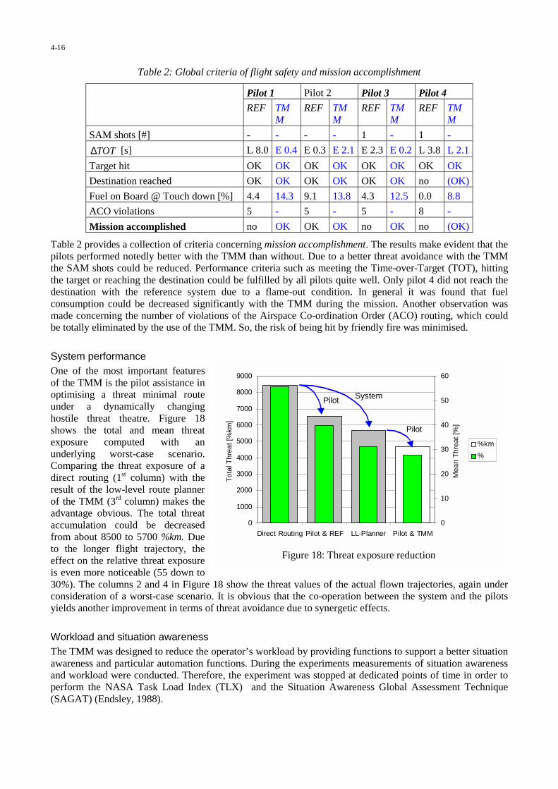
0
1000
2000
3000
4000
5000
6000
7000
8000
9000
Direct Routing Pilot & REF LL-Planner Pilot & TMM
Tot
alT
hrea
t[%
km]
0
10
20
30
40
50
60
Mea
nT
hrea
t[%
]
%km
%
Pilot
Pilot
System
Figure 18: Threat exposure reduction
Table 2: Global criteria of flight safety and mission accomplishment
Pilot 1 Pilot 2 Pilot 3 Pilot 4
REF TMM
REF TMM
REF TMM
REF TMM
SAM shots [#] - - - - 1 - 1 -
TOT∆ [s] L 8.0 E 0.4 E 0.3 E 2.1 E 2.3 E 0.2 L 3.8 L 2.1
Target hit OK OK OK OK OK OK OK OK
Destination reached OK OK OK OK OK OK no (OK)
Fuel on Board @ Touch down [%] 4.4 14.3 9.1 13.8 4.3 12.5 0.0 8.8
ACO violations 5 - 5 - 5 - 8 -
Mission accomplished no OK OK OK no OK no (OK)
Table 2 provides a collection of criteria concerning mission accomplishment. The results make evident that thepilots performed notedly better with the TMM than without. Due to a better threat avoidance with the TMMthe SAM shots could be reduced. Performance criteria such as meeting the Time-over-Target (TOT), hittingthe target or reaching the destination could be fulfilled by all pilots quite well. Only pilot 4 did not reach thedestination with the reference system due to a flame-out condition. In general it was found that fuelconsumption could be decreased significantly with the TMM during the mission. Another observation wasmade concerning the number of violations of the Airspace Co-ordination Order (ACO) routing, which couldbe totally eliminated by the use of the TMM. So, the risk of being hit by friendly fire was minimised.
System performanceOne of the most important featuresof the TMM is the pilot assistance inoptimising a threat minimal routeunder a dynamically changinghostile threat theatre. Figure 18shows the total and mean threatexposure computed with anunderlying worst-case scenario.Comparing the threat exposure of adirect routing (1st column) with theresult of the low-level route plannerof the TMM (3rd column) makes theadvantage obvious. The total threataccumulation could be decreasedfrom about 8500 to 5700 %km. Dueto the longer flight trajectory, theeffect on the relative threat exposureis even more noticeable (55 down to30%). The columns 2 and 4 in Figure 18 show the threat values of the actual flown trajectories, again underconsideration of a worst-case scenario. It is obvious that the co-operation between the system and the pilotsyields another improvement in terms of threat avoidance due to synergetic effects.
Workload and situation awarenessThe TMM was designed to reduce the operator’s workload by providing functions to support a better situationawareness and particular automation functions. During the experiments measurements of situation awarenessand workload were conducted. Therefore, the experiment was stopped at dedicated points of time in order toperform the NASA Task Load Index (TLX) and the Situation Awareness Global Assessment Technique(SAGAT) (Endsley, 1988).
4-16
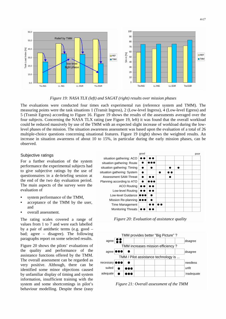
situation gathering: Route
situation gathering: System
situation gathering: Timing
situation gathering: ACO
good poor
Planning according to ATO
Low-level Routing
ACO Routing
Assessment SAM-Threat
Mission Re-planning
Monitoring Threats
Time Management
Low-level Guidance
Figure 20: Evaluation of assistance quality
suited unfit
necessary needless
TMM provides better "Big Picture" ?agree disagree
TMM increases mission efficiency ?agree disagree
TMM / Pilot assistance technology is ...
adequate inadequate
Figure 21: Overall assessment of the TMM
0,0
10,0
20,0
30,0
40,0
50,0
60,0
Tra ING LL ING LL EGR Tra EGR
Tas
kLo
adIn
dex
[%]
REF
TMM
Relief by TMM
low-levelflight phase
0
10
20
30
40
50
60
70
80
90
100
Tra ING LL ING LL EGR Tra EGR
SA
in[%
]
REF
TMM
Figure 19: NASA TLX (left) and SAGAT (right) results over mission phases
The evaluations were conducted four times each experimental run (reference system and TMM). Themeasuring points were the task situations 1 (Transit Ingress), 2 (Low-level Ingress), 4 (Low-level Egress) and5 (Transit Egress) according to Figure 16. Figure 19 shows the results of the assessments averaged over thefour subjects. Concerning the NASA TLX rating (see Figure 19, left) it was found that the overall workloadcould be reduced massively by use of the TMM with an expected slight increase of workload during the low-level phases of the mission. The situation awareness assessment was based upon the evaluation of a total of 26multiple-choice questions concerning situational features. Figure 19 (right) shows the weighted results. Anincrease in situation awareness of about 10 to 15%, in particular during the early mission phases, can beobserved.
Subjective ratingsFor a further evaluation of the systemperformance the experimental subjects hadto give subjective ratings by the use ofquestionnaires in a de-briefing session atthe end of the two day evaluation period.The main aspects of the survey were theevaluation of
• system performance of the TMM,• acceptance of the TMM by the user,
and• overall assessment.
The rating scales covered a range ofvalues from 1 to 7 and were each labelledby a pair of antithetic terms (e.g. good –bad; agree – disagree). The followingparagraphs report on some selected results.
Figure 20 shows the pilots’ evaluations ofthe quality and performance of theassistance functions offered by the TMM.The overall assessment can be regarded asvery positive. Although, there can beidentified some minor objections causedby unfamiliar display of timing and systeminformation, insufficient training with thesystem and some shortcomings in pilot’sbehaviour modelling. Despite these (easy
4-17

to remove) deficits the assessment of the implemented prototype was almost optimal.
Figure 21 shows some selected but representative results of the overall assessment given by the pilots. Thesubjects fully agreed with the hypothesis that the TMM provides a better big picture in terms of globalsituation awareness. TMM is qualified to increase mission efficiency according to the pilots. The operatorsregarded the presented technology of Tactical Mission Management and crew assistance to be absolutelynecessary, suited and adequate.
5 CONCLUSIONSAfter having gathered years of experience in cognitive flight-deck automation and crew assistance, the timehas come to gain the results of exceedingly successful efforts in the field of military transport as well ascombat aircraft. The functional breakdown of the Crew Assistant Military Aircraft (CAMA), representing theair-transport domain, and on the other hand the Tactical Mission Management System, being a cockpitautomation system for combat aircraft, has been derived from a model of human information processing, inorder to approach a co-operative automation principle. Laboratory prototype systems have been evaluatedwith Air Force pilots in simulator and flight trials. Besides the fact that the approach was very wellappreciated by the pilots, objective measures evidence a significant increase in performance in terms of threatavoidance and mission efficiency. These results could be achieved in conjunction with a noticeable reductionof the terrain collision risk and the operator’s workload. Therefore, the system approach is highlyrecommended for application in the advancement and automation of future aircraft as well as other militaryand non-military application domains, where ever operator situation awareness and decision-making is crucial.
6 LITERATUREBillings, Charles E. (1991). Human centered automation: a concept and guidelines. Technical Memorandum
103885. NASA Ames Research Center, Moffett Field, CA.
Billings, Charles E. (1997). Aviation Automation. The Search for a Human-Centered Approach. LawrenceErlbaum Associates: Mahwah, NJ.
Endsley Mica R. (1988). Design and Evaluation for Situation Awareness Enhancement. In Proccedings of theHuman Factots Society, 32nd Annual Meeting. Santa Monica, CA.
Endsley, Mica R. (1988), Situation Awareness Global Assessment Technique (SAGAT). National Aerospaceand Electronics Conference.
Flemisch, Frank & Onken, Reiner (1998). The Cognitive Assistant System and its Contribution to effectiveMan/Machine Interaction. The Application of Information Technology (Computer Science) in MissionSystems. NATO RTA SCI. Monterey, USA.
Frey, Andreas; Lenz, André & Onken, Reiner (1999). Core elements of the Cognitive Assistant SystemCAMA. In: Advanced Mission Management System Integration Technologies for Improved TacticalOperations. NATO System Concepts and Integration Panel Symposium. Florence Italy. 27-29 Sept. 1999.
Hollnagel, Erik (1995). Automation, coping, and control. In: Post HCI’95 Conference Seminar on Human-MachineInterface in Process Control. Hieizan, Japan. July 17-19, 1995.
Johannsen, Gunnar (1993). Mensch-Maschine-Systeme. Springer Verlag.
Onken, Reiner (1994). Basic Requirements Concerning Man-Machine Interactions in Combat Aircraft.Workshop on Human Factors/Future Combat Aircraft. Ottobrunn, Germany. Oct. 1994
Onken, Reiner & Walsdorf, Anton (2000). Assistant Systems for Vehicle Guidance: Cognitive Man-MachineCooperation. In: 4th International Conference on IT for Balanced Automation Systems – BASYS 2000.Berlin, Germany. 27-29 September 2000.
Prévôt, Thomas; Gerlach, Marc; Ruckdeschel, Wilhelm; Wittig, Thomas & Onken, Reiner (1995). Evaluationof intelligent on-board pilot assistance in in-flight field trials. In: 6th IFAC/IFIP/IFORS/IEA Symposium onAnalysis, Design and Evaluation of Man-Machine Systems. Massachusetts Institute of Technology,Cambridge, MA. June 1995.
4-18

Putzer, Henrik & Onken, Reiner (2001). COSA – A Generic Approach towards a Cognitive SystemArchitecture. In: The Cognitive Work Process: Automation and Interaction. 8th European Conference onCognitive Science Applications in Process Control, CSAPC’01. Munich, Ge. 24.-26. September, 2001.
Rasmussen, Jens (1983). Skills, Rules, and Knowledge; Signals, Signs, and Symbols, and other Distinctions inHuman Performance Models. In: IEEE Transactions on Systems, Man, and Cybernetics. SMC-13(3):257-266.
Rasmussen, Jens (1986). Information Processing and Human-Machine Interaction. An Approach to CognitiveEngineering. North-Holland.
Rouse, W.B. (1991). Design for Success: A Human-Centered Approach to Successful Products andSystems.Wiley, New York. 1991
Schubert, A. & Schulte, A. (2001), Automatische Generierung eines pilotengerechten Tiefflugprofils mitempirischer Modellparameteradaption für die Flugführung. Deutscher Luft- und Raumfahrtkongress 2001.Hamburg. 17. bis 20. September 2001.
Schulte, Axel & Onken, Reiner (1995). Empirical modelling of pilot’s visual behaviour at low altitudes. In: 6th
IFAC/IFIP/IFORS/IEA Symposium on Analysis, Design and Evaluation of Man-Machine Systems. pp 169- 174. Massachusetts Institute of Technology, Cambridge, MA. June 1995.
Schulte, Axel & Stütz, Peter (1998). Evaluation of the Crew Assistant Military Aircraft (CAMA) in SimulatorTrials. In: NATO Research and Technology Agency, System Concepts and Integration Panel. Symposiumon Sensor Data Fusion and Integration of Human Element. Ottawa, Canada.
Schulte, Axel; Stütz, Peter & Klöckner, Wolfgang (1999). Cognitive Concepts in Tactical MissionManagement. In: NATO Research and Technology Agency, System Concepts and Integration Panel.Symposium on Advanced Mission Management and System Integration Technologies for ImprovedTactical Operations. Florence, Italy. September 27-29, 1999.
Schulte, Axel & Stütz, Peter (2000). Cognitive Concepts in Mission Management for Air-to-Ground AttackAircraft. In: Third International Conference on Engineering Psychology and Cognitive Ergonomics.Edinburgh, UK. October 25-27, 2000.
Schulte, Axel; Stütz, Peter & Klöckner, Wolfgang (2001/a). Cognitive Flight-Deck Automation for MilitaryAircraft Mission Management. In: 9th International Conference on Human-Computer Interaction. HCIInternational 2001. New Orleans, LA. August 5-10, 2001.
Schulte, Axel; Stütz, Peter & Klöckner, Wolfgang (2001/b). Cognitive Automation for Attack Aircraft:Concept and Prototype Evaluation in Flight Simulator Trials. In: The Cognitive Work Process: Automationand Interaction. 8th European Conference on Cognitive Science Applications in Process Control,CSAPC’01. Munich, Ge. 24.-26. September, 2001.
Stütz, Peter & Schulte, Axel (2000). Evaluation of the Cockpit Assistant Military Aircraft CAMA in flighttrials. In: Third International Conference on Engineering Psychology and Cognitive Ergonomics.Edinburgh, UK. October 25-27, 2000.
Stütz, Peter; Adam, Volkmar & Schönhoff, A. (2001). Missionsmanagement für ein hochfliegendes,unbemanntes Luftfahrzeug im kontrollierten Luftraum: Betriebsverfahren und Avionikkonzept. In:Deutscher Luft- und Raumfahrtkongress 2001, Hamburg. 17. bis 20. September 2001.
Stütz, Peter & Onken, Reiner (2001). Adaptive Pilot Modelling within Cockpit Crew Assistance: Concept,Realisation and Results. In: The Cognitive Work Process: Automation and Interaction. 8th EuropeanConference on Cognitive Science Applications in Process Control, CSAPC’01. Munich, Ge. 24.-26.September, 2001.
Walsdorf, Anton; Putzer, Henrik & Onken, Reiner (1999). The cognitive process and ist application withincockpit assistant systems. In: IEEE / IEEJ / JSAI International Conference on Intelligent TransportationSystems. Tokyo, Japan. 5-8 October 1999.
Wiener, Earl L. & Nagel, D.C. (1988). Human Factors in Aviation. Academic Press. San Diego, CA.
4-19

This page has been deliberately left blank
Page intentionnellement blanche

On-Board Decision Support through the Integration of Advanced InformationProcessing and Human Factors Techniques: The POWER Project
H.H. (Henk) Hesselink ([email protected]), G.D.R. (Rolf) Zon ([email protected]),F. (Frank) Tempelman ([email protected]), J.W. (Jelle) Beetstra ([email protected]),
A.M. (Arjen) Vollebregt ([email protected]), D.P. (Daan) Hannessen ([email protected])
National Aerospace Laboratory, NLR Anthony Fokkerweg 2, 1059 CM Amsterdam
The Netherlands
SummaryAs advanced crew support technologies will be available more and more in future military aircraft, it is necessaryto have a good understanding of the possibilities in this area, taking into account operational demands, technicalpossibilities, human factors, evaluation, and validation aspects. A Crew Assistant (CA) is a decision supportsystem for air crew, designed to improve mission effectiveness and redistribute crew workload in such a way thatthe crew can concentrate on its prime tasks.
The POWER (Pilot Oriented Workload Evaluation and Redistribution) project is a Netherlands NationalTechnology Project. The project is aimed at demonstrating a generic CA environment and individual tacticaldecision support tools to military pilots in a simulated environment, the NSF (National Simulation Facility), a six-degrees of freedom cockpit in a visual dome.
The project is a technology demonstration project to show new CA features. An advanced software architecturehas been set up, based on multi-agent technology, where software "agents" co-operate in sharing information andusing resources on an as-needed basis. Each agent is an autonomous piece of software that is able to anticipatecourses of action and performs its function pro-actively.
Several prototypes of crew assistant agents have been developed and integrated in order to facilitate a CAdemonstrator
A large-scale experiment with operational pilots from the Royal Netherlands Air Force (RNLAF) has been carriedout to demonstrate the effects of CA technology as decision support, to validate tools, and to measure the effectsof on-board decision support in enhancing pilot situational awareness.
This paper describes the demonstration CA environment and provides insight into the different CA components.Part one describes the environment as a generic CA architecture that can be installed on a simple work station aswell as in a full-scale simulation environment. The second part of this paper describes the aforementionedexperiment, where NCMM and the contents of the experiment will be detailed.
5-1
Paper presented at the RTO SCI Lecture Series on “Tactical Decision Aids and Situational Awareness”, held in Amsterdam,The Netherlands, 1-2 November 2001; Sofia, Bulgaria, 8-9 November 2001; Madrid, Spain, 12-13 November 2001;
Maryland, United States, 19-20 November 2001, and published in RTO-EN-019.
PART I: A CREW ASSISTANT ARCHITECTURE
1 IntroductionSoftware and human factors are becoming major part of current and future on-board avionics. Currentdevelopments in software engineering and advanced information processing techniques enable complex crewassistant applications, especially support of the aircraft crew in carrying out primary and secondary tasks is moreand more provided by electronic systems. Application of crew assistants in fighter aircraft is a challenging task,both for the research and development of the software, as for the human factors aspects concerning its optimal useand trust of the pilot in the system.
The POWER (Pilot Oriented Workload Evaluation and Redistribution) project, is a Netherlands NationalTechnology Project. The project is aimed at demonstrating a generic Crew Assistant (CA) environment andindividual tactical decision support tools to pilots in a simulated environment, the NSF (National SimulationFacility), a six-degrees of freedom F-16 cockpit in a visual dome. This demonstrator has been the focus of theproject.
Current progress in advanced information processing, new advances in human factors, and the possibility tovalidate new avionics so that pilots learn to trust the system, form the basis for this paper in order to supportRNLAF in the acquisition and usage of new aircraft. In this paper, a generic simulation environment is discussed,that enables different levels of crew assistant demonstration and experimentation. The environment proposed isbased on multi-agent technology, where a generic Crew Assistant environment can be plugged onto a "simple"scenario generator on a work station or to a full-scale flight simulation facility, like the NSF.
Several prototypes of CA agents have been developed and integrated in order to facilitate the CA demonstrator:• A profile recognition agent takes input from different sensors and recognises profiles in a data fusion
assembled picture. The agent reasons with uncertainty in the observation and uses Bayesian Belief Networksto model the profile and sensor's characteristics.
• A manoeuvre prediction agent assesses an opponent's manoeuvre and predicts the patters that will be flownwhen in air-to-air combat. This tool is based on case-based reasoning technology.
• The NCMM (NLR counter Measure Manager) agent advises counter measures against threats, e.g. SAM-sites. The tool is based on expert system technology.
• An HMI is designed with an NLR built tool, NADDES (NLR Avionics Display Development and EvaluationSystem), for increasing pilot situation awareness.
This paper will provide an overview of the POWER project. It has been set up in two parts, where the first partdescribes the generic CA architecture and part two describes a large scale experiment that has been carried out.Chapter two will introduce crew assistant technology and chapter three will describe the software architecture,which is based on multi-agent technology. Chapter four describes the technical aspects of the simulationenvironment the experiment. Chapter five describes the setting and results of this experiment.
2 Crew Assistant TechnologyFighter pilot's workload is rapidly increasing. Modern military operations take place in a complex environment toaccomplish a spectrum of missions. The most important factor in the increase in workload concerns theoperational environment of current fighter aircraft:• the increase of the complexity of the military environment in general (e.g. combined joint task forces, peace
keeping/peace enforcement).• the increase of the complexity of the types of missions to be flown.• the increase in the number of different (kinds of) threats.
5-2

Another factor is the technological developments of fighter aircraft. The increase in aircraft speed and aircrafttypes and on-board systems causes the aircraft itself to become much more difficult to manage, putting morepressure on the crew. During high-stress situations, the crew can get overloaded with information, while it has toperform a multitude of actions. Figure 1 illustrates the possible information overload and decision makingprocess.
Figure 1. The information requirements of the crew [Yannone, 1985].
A Crew Assistant is an on-board decision support system that supports the crew in performing its mission. It aimsat improving mission effectiveness, flight safety, and/or survivability by providing the crew with concise andrelevant information, depending on the mission phase, thus enabling the crew to concentrate on mission decisionsand make more effective decisions. [Urlings 1995]. Crew Assistants are decision support systems for air crew,designed to improve mission effectiveness and redistribute crew workload in such a way that the crew canconcentrate on its prime tasks. Ideally, a CA assists a pilot, or other crew members, by providing the followingkind of functions:• Acquire the necessary information and merge the input from different sensor and information systems into
one timely and consistent view of the current situation (the status of different on-board systems, the situationoutside, etc.).
• Process the merged information to give advice (weapons selection, route planning, tactics evaluation, fuelmanagement, etc.).
• Perform tasks autonomously when so instructed by the pilot or another crew member (autopilot, targettracking, systems monitoring, etc.).
As advanced crew support technologies will be available more and more in future (military) aircraft, it isnecessary to have a good understanding of the possibilities in this area, taking into account operational demands,technical possibilities, human factors, evaluation, and validation aspects.
5-3
The current state-of-the-art in advanced information processing now makes intelligent pilot assistant through aCA technically feasible, including real-time on-board data acquisition, fusion, and processing. Advancedinformation processing techniques, like expert systems and neural networks, and methods for constraintreasoning, case based reasoning and reasoning with uncertain and incomplete information, can be used in themilitary cockpit. Research in Human Factors technology aspects, will make the techniques available to the humanoperator. For an overview of systems and technologies, see e.g. [Boers 1999], [Van Gerwen 2000-1],[Verhoeven 2000].
In the course of the years, several CA programs have been set up. The Crew Assistant Military Aircraft (CAMA)is a German DoD programme that investigates the use of an intelligent electronic crew member in the militarytransport application [Strohal 1997], [Frey 1999]. Within the programme, flight simulator trials have beenperformed in the simulator of the University of the German Armed Forces. Flight experiments are scheduled in anin-flight simulator. Hands-on experience and feed back from pilots is a factor in the development of systems thatmust be gained. One project that takes a human factors perspective on CAs is the Cognitive Cockpit (COGPIT)project, that has been set up by the UK Ministry of Defence in conjunction with the Defence Evaluation ResearchAgency (DERA). This project seeks to develop a theoretically grounded, human-centred approach for guiding aprincipled development of intelligent pilot aiding concepts for cockpit automation [Taylor 1998], [Taylor 2000]. Itresearches the cognitive engineering aspects of the pilots to couple knowledge-based systems for situationassessment and decision support with conceptsand technologies for adaptive automation and cockpit adaptiveinterfaces. Other CA projects are Pilot's Associate (PA) [Holmes 1991], Rotorcraft Pilot's Associate (RPA)[Collucci 1995], CoPilote Electronique, Cockpit Assistant System (CASSY) [Onken 1997], and the ElectronicCopilot (ECOP) [Stein 1987].
These programs take either a technological or a human centred focus on CAs. We believe that for a goodintegration of CA technology in the cockpit, the relationship between the fields of Advanced InformationProcessing (AIP) and Human Factors (HF) should be exploited further. The POWER project brings together thefields of military operations research, advanced information processing and human factors. It combinestechniques from artificial intelligence and human machine interaction in such a way that pilots are supported withadvanced crew assistants, wherewith the information is provided to them in a sense that a fused picture of theworld emerges. Apart from the technological aspects, the POWER project has strong roots in the analysis ofrequirements and needs from operational fighter pilots. The project will help decision makers in technologyassessments for acquiring new aircraft and equipment and manufacturers in making strategic decisions ontechnological programmes.
In many cases, information will be time dependent, inaccurate and incomplete. The use of uncertain andincomplete information should be further investigated and must be considered in the design of the HumanMachine Interface (HMI). The project therefore, focuses on the following challenges:• Provide a flexible demonstration environment for crew assistant technology, based on operational demands
from fighter pilots.• Provide examples of crew assistant technology, based on new advanced AIP and HF aspects.• Provide insight in new real-time reasoning techniques for reasoning with uncertainty.• Provide a quantitative scientific base that proves the benefit and user acceptance of CA technology.• Perform experiments with the demonstration environment that lays a basis for further work in the field of
introducing CA technology to the RNLAF.
3 The ArchitectureUntil recently, work in on-board automation focussed on the introduction of single self-supporting functions. Theadvantage of this is high reliability in case of single failures, where other independent systems take over. Insteadof relying on the information that one sensor provides, CA decision support functions in essence focus on the
5-4
integration of information and the provision of a complex and fused picture to the pilot. This creates new demandsfor the software and hardware architecture and the human factors aspects.
Decision support functions are concerned with data acquisition, fusion, and processing and use information fromdifferent sources, so that an architecture is needed, where the system does not rely on one information source anddoes not contain any critical processing nodes. We believe that an architecture based on agent technology can andwill play an important role in the near future in avionics. Agent-based architectures have been introduced for on-board decision support systems in e.g. TANDEM [Barrouil 1999], the Cognitive Cockpit [Taylor 2000], and foron board multi-sensor data fusion [Bossé 1999].
The strength of software agents is that they can be made to interact with other software agents or human users.Agents are “small” autonomous black boxes, which handle their own clearly defined tasks. A system of agentsthat co-operates is called a multi-agent system. Agents, if well-designed as separate processing units, enablecommunication between multiple subsystems, without putting a strain on one specific part of the system. Theirloose coupling provides a possibility to introduce new technology throughout the aircraft's lifetime, especially at"end of the line" functions, like weapon systems, where it is relatively easy to validate new technology.
This chapter will give an overview of the proposed multi-agent architecture and will describe the most importantCA components that have been provided with the POWER project.
3.1 A Functional Architecture based on Multi-Agent TechnologyThe proposed architecture has been based on the results of earlier projects, like the EUCLID (European Co-operation for the Long Term in Defence) Research and Technology project 6.5 [Zuidgeest 1995]. This NLR-ledproject on CAs for military aircraft started with extensive user interviews to establish an inventory of operationaluser problems and needs for pilots flying F-16, Tornado and AM-X. The project came up with a generic on-boardCA architecture and indicated a challenge in the application of multi-agent systems and knowledge based systems.
The architecture that has been set up for the POWER project distinguishes four groups of functional agents. Thegroups are (1) data and information input agents, like sensors and the multi-sensor data fusion agent, (2) dataprocessing agents which form the actual crew assistant functions, (3) information output agents mainly to thepilot, and finally, (4) the weapon agents. Apart from these, other agents perform functions for controlling andmonitoring the overall system's status and health. In this paper, we will focus on the functional part of crewassistants, see figure 2.
The four functional groups further subdivided in seven subgroups (see slight colour differences in figure 2),discussed below.
Internal sensor agents are system components that transform the raw input data from the sensor hardware to anunderstandable format for the Multi-Sensor Data Fusion (MSDF) component. In our example, we includedsensors to detect and distinguish SAMs and to detect incoming missiles.• A Radar Warning Receiver (RWR) provides the position of ground threats, including an indication whether
the SAM is in search, track, or guidance.• The Missile Launch Warning (MLW) is a passive infrared plume detector that provides missile information
while its motor is burning.• The Missile Approach Warning is an active short range radar that detects a missile body, usually in a two to
three miles range.
5-5

Figure 2. Functional architecture of on-board agents
External sensor agents are components that obtain their information from sensors or information systems that arephysically located outside the aircraft, for example an AWACS or a Link-16. These sensor agents transform dataand information into an understandable format for the MSDF agent or for the CA agents.
The Multi-Sensor Data Fusion agent combines the sensor information from all internal and external sensors into acombined sensor data picture. This agent may perform complex situation assessment tasks. In the currentimplementation, this is a fusion process that only provides the information to the CA's that is really necessary forthe CAs to perform their task. Different projects have already shown the complexity of a multi-sensor data fusionprocess and have proposed architectures [TA-10], [Bossé 1999]. The latter proposes an agent based architecturefor multi-sensor data fusion, which shows the flexibility of agent systems, where agents can delegate tasks to(sub-)agents.
Crew Assistant agents are the intelligent pilot support functions. The ones mentioned in figure 2 are elaborated inthe POWER project (based on [Zuidgeest 1995]), however, the range of pilot support functions is not limited tothese. CAs can be further classified into functions as information finding in the fused sensor picture (like profilerecognition, see section 3.2), pilot advice (like manoeuvre prediction, see section 3.3, and NLR's Counter MeasureManager, see section 3.4 and chapter 4), pilot monitoring, mission monitoring, etc. Other classifications arepossible, like [Barrouil 1999], [Taylor 2000].
Weapon agents control the weapon delivery. In this example, a number of softkill weapons to countermeasureground threats is displayed. Their intelligence for example consists of providing the correct jamming against arecognized threat or dispensing a complex pattern of chaff and flare.
5-6

The Display agent is responsible for assembling an integrated picture of crew assistant information and forprioritizing information provision to the pilot. If necessary, it can hold information that is considered lessimportant at a certain moment or less time critical, if the pilot is assumed to get overloaded with information.Once the situation is more relaxed, it can decide to provide this information. An even more intelligent displayagent can decide what information should be provided on which cockpit display, or what information should beprovided on which part of the cockpit display and automatically adapt the contents of the available displays if at(a certain part of) one of the displays an information overload is eminent. This technology, however, should beintroduced with care [Verhoeven 2000].
The Human Machine Interface agent is the actual cockpit display that provides the information on the userinterface. It may take inputs from the user.
For a generic CA demonstration environment, we require a crew assistant independently from its operationalenvironment. Obviously, a generic demonstration environment, especially a complex one as a crew assistantrequires a number of general tools, like scenario generation tools and environment databases. The currentlydeveloped environment connects the tools to ITEMS, which provides a topographical scenario and an F-16aircraft model. This enables the possibility to connect the crew assistant to e.g. a fly box, see figure 3, to theNLR's F-16 mock up simulator, and to the NSF, see figure 4.
Figure 3. Flybox and workstation configuration Figure 4. National Simulation Facility
3.2 Reasoning with Uncertainty for Profile RecognitionReasoning with uncertainty will be an important aspect of CA technology. Even the information from a fusedsensor picture will usually contain unclear elements. To investigate possibilities of real-time reasoning withuncertainty, a profile recognition agent was developed.
Any crew assistant will gather information from its environment, process this information, and act upon it.Probabilistic methods for reasoning with uncertainty have gained a lot of interest in the last few decades. Theintroduction of Bayesian Belief Networks [Pearl 1988], [Jensen 1996] made practical application of probabilisticreasoning possible. Most applications have been targeted at decision support in the medical domain where thevariables in the model typically have a few states and no real-time constraints exist. In contrast, the decisionsupport systems for fighter pilots have to deal with many real-valued sensor readings that provide measurementsevery split second and that need to be processed in real-time [Van Gerwen 2000-2].
5-7

Suppose an aircraft has on-board sensors to identify profiles. In this example, different profiles are considered andthe aircraft sensors can measure length, width, and speed of the objects that are sensed. However, sensor accuracydepends on weather conditions, in particular visibility, cloud coverage, and humidity. This scenario is modelledthrough a Bayesian Belief Network as given in figure 5. Each of the profiles modelled, has an a-prior probabilitydistribution.
Length Width Speed
LengthMeasure WidthMeasure
Object
Radar
CloudCoverageVisibility
WeatherType
Humidity
Figure 5. Bayesian Belief Networks for profile recognition
The goal of this research is to look into the possibility of creating an anytime algorithm for a Bayesian BeliefNetwork. Anytime algorithms are algorithms that trade performance for time. As the amount of time is increased,an anytime algorithm improves the quality of the output. One of the features of anytime algorithms is that it canprovide intermediate results at any moment, so that the available processing power and time can be regulated.
Propagating evidence in a Bayesian belief network can be a very time-consuming task (it is NP-hard). Onesolution might be an algorithm that uses state-space abstraction. We examined different AI techniques, likeBreadth First, Breadth First Split, and Highest Belief First. Figure 6 gives the results of the different methods.
In the CA agent, we have shown that state-space abstraction in combination with a strategy such as Highest BeliefFirst has interesting features required for an anytime algorithm. The proposed method outperforms simplermethods like Breadth First and Breadth First Split.
5-8
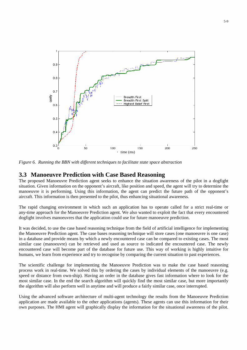
time (ms)
Figure 6. Running the BBN with different techniques to facilitate state space abstraction
3.3 Manoeuvre Prediction with Case Based ReasoningThe proposed Manoeuvre Prediction agent seeks to enhance the situation awareness of the pilot in a dogfightsituation. Given information on the opponent’s aircraft, like position and speed, the agent will try to determine themanoeuvre it is performing. Using this information, the agent can predict the future path of the opponent’saircraft. This information is then presented to the pilot, thus enhancing situational awareness.
The rapid changing environment in which such an application has to operate called for a strict real-time orany-time approach for the Manoeuvre Prediction agent. We also wanted to exploit the fact that every encountereddogfight involves manoeuvres that the application could use for future manoeuvre prediction.
It was decided, to use the case based reasoning technique from the field of artificial intelligence for implementingthe Manoeuvre Prediction agent. The case bases reasoning technique will store cases (one manoeuvre is one case)in a database and provide means by which a newly encountered case can be compared to existing cases. The mostsimilar case (manoeuvre) can be retrieved and used as source to indicated the encountered case. The newlyencountered case will become part of the database for future use. This way of working is highly intuitive forhumans, we learn from experience and try to recognise by comparing the current situation to past experiences.
The scientific challenge for implementing the Manoeuvre Prediction was to make the case based reasoningprocess work in real-time. We solved this by ordering the cases by individual elements of the manoeuvre (e.g.speed or distance from own-ship). Having an order in the database gives fast information where to look for themost similar case. In the end the search algorithm will quickly find the most similar case, but more importantlythe algorithm will also perform well in anytime and will produce a fairly similar case, once interrupted.
Using the advanced software architecture of multi-agent technology the results from the Manoeuvre Predictionapplication are made available to the other applications (agents). These agents can use this information for theirown purposes. The HMI agent will graphically display the information for the situational awareness of the pilot.
5-9
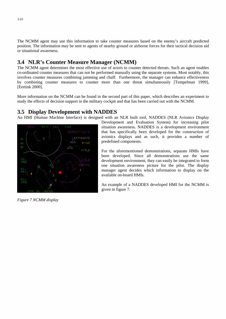
The NCMM agent may use this information to take counter measures based on the enemy’s aircraft predictedposition. The information may be sent to agents of nearby ground or airborne forces for their tactical decision aidor situational awareness.
3.4 NLR’s Counter Measure Manager (NCMM)The NCMM agent determines the most effective use of actors to counter detected threats. Such an agent enablesco-ordinated counter measures that can not be performed manually using the separate systems. Most notably, thisinvolves counter measures combining jamming and chaff. Furthermore, the manager can enhance effectivenessby combining counter measures to counter more than one threat simultaneously [Tempelman 1999],[Eertink 2000].
More information on the NCMM can be found in the second part of this paper, which describes an experiment tostudy the effects of decision support in the military cockpit and that has been carried out with the NCMM.
3.5 Display Development with NADDESAn HMI (Human Machine Interface) is designed with an NLR built tool, NADDES (NLR Avionics Display
Development and Evaluation System) for increasing pilotsituation awareness. NADDES is a development environmentthat has specifically been developed for the construction ofavionics displays and as such, it provides a number ofpredefined components.
For the aforementioned demonstrations, separate HMIs havebeen developed. Since all demonstrations use the samedevelopment environment, they can easily be integrated to formone situation awareness picture for the pilot. The displaymanager agent decides which information to display on theavailable on-board HMIs.
An example of a NADDES developed HMI for the NCMM isgiven in figure 7.
Figure 7 NCMM display
5-10
1
22
2
3
41
SA 3 SA 3
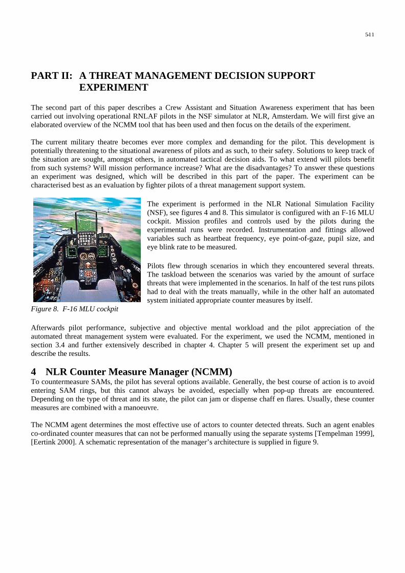
PART II: A THREAT MANAGEMENT DECISION SUPPORTEXPERIMENT
The second part of this paper describes a Crew Assistant and Situation Awareness experiment that has beencarried out involving operational RNLAF pilots in the NSF simulator at NLR, Amsterdam. We will first give anelaborated overview of the NCMM tool that has been used and then focus on the details of the experiment.
The current military theatre becomes ever more complex and demanding for the pilot. This development ispotentially threatening to the situational awareness of pilots and as such, to their safety. Solutions to keep track ofthe situation are sought, amongst others, in automated tactical decision aids. To what extend will pilots benefitfrom such systems? Will mission performance increase? What are the disadvantages? To answer these questionsan experiment was designed, which will be described in this part of the paper. The experiment can becharacterised best as an evaluation by fighter pilots of a threat management support system.
The experiment is performed in the NLR National Simulation Facility(NSF), see figures 4 and 8. This simulator is configured with an F-16 MLUcockpit. Mission profiles and controls used by the pilots during theexperimental runs were recorded. Instrumentation and fittings allowedvariables such as heartbeat frequency, eye point-of-gaze, pupil size, andeye blink rate to be measured.
Pilots flew through scenarios in which they encountered several threats.The taskload between the scenarios was varied by the amount of surfacethreats that were implemented in the scenarios. In half of the test runs pilotshad to deal with the treats manually, while in the other half an automatedsystem initiated appropriate counter measures by itself.
Figure 8. F-16 MLU cockpit
Afterwards pilot performance, subjective and objective mental workload and the pilot appreciation of theautomated threat management system were evaluated. For the experiment, we used the NCMM, mentioned insection 3.4 and further extensively described in chapter 4. Chapter 5 will present the experiment set up anddescribe the results.
4 NLR Counter Measure Manager (NCMM)To countermeasure SAMs, the pilot has several options available. Generally, the best course of action is to avoidentering SAM rings, but this cannot always be avoided, especially when pop-up threats are encountered.Depending on the type of threat and its state, the pilot can jam or dispense chaff en flares. Usually, these countermeasures are combined with a manoeuvre.
The NCMM agent determines the most effective use of actors to counter detected threats. Such an agent enablesco-ordinated counter measures that can not be performed manually using the separate systems [Tempelman 1999],[Eertink 2000]. A schematic representation of the manager’s architecture is supplied in figure 9.
5-11

MSDFHMI
MSDF-RM
ITEMS
ITEMS-RMRCM Activator CMT Scheduler System
RCM KB CMT KB
RESOURCE MANAGER
Figure 9. The NCMM in the simulation environment.
The MSDF agent delivers environment data, most notably sensor tracks and threat information, to the resourcemanager. The resource manager is the core of the NCMM. It consists of two rule-based knowledge bases: theReflex Counter Measure (RCM) Knowledge Base and the Counter Measure Technique (CMT) Knowledge Base.The first associates sensor tracks directly to single counter measures (e.g., chaff, flare, a jamming technique, amanoeuvre), in situations where immediate action is required. The latter connects threats, i.e., fused sensor tracks,under certain positional conditions to a series of counter measures, after which the dynamically planning CMTScheduler fits these into the existing counter measure schedule.
An example of the represented CMT knowledge is given in table 1. Rule number 12 (highlighted in the table), forexample, represents what can be done to counter a threat of type SAM1 in track (T) mode, which has threat level(lethality) 4 on a scale of 0 to 10. The SAM1 is detected by two sensors, the Radar Warning Receiver (R) and theALQ (J). With an expected effectiveness of 8 on a similar scale, it can be countered by a combination of Range-Gate Pull-Off (a jamming technique) followed by dispensing 4 bundles of chaff with an interval of 0.2 seconds(4C0.2), if the condition on the threat’s position is fulfilled.
The knowledge in the resource manager is highly flexible. It can be adapted easily to include newly constructedcounter measure techniques and it can be modified to reflect the availability of other agents in the aircraft inwhich the NCMM is running.
Various operational modes are available in the NCMM. These determine the availability of assets in variouscircumstances. For example, it can be necessary to not use jamming counter measures, as the enemy can detectthese. Selecting the operational mode ‘Run Silent’ will then take care of this. Furthermore, the NCMM agentsupports system modes, determining the amount of automation of the system. These vary from manual, in whichcase only advises are given, to fully automatic, in which case all counter measures except manoeuvres areexecuted automatically and in time. For reasons of pilot convenience, manoeuvres will only be advised.
5-12

ID Threat Mode TL Sensors Effectiveness GCMT1 SAM1 S 3 R 5 OTCONDITION: None# Simple example: SAM1 search radar (low TL) detected by RWR only; Turn to evade the site.
2 SAM1 S 3 R+J 8 N1SCONDITION: None# As above, only now the site is also detected by the ALQ, so jamming can be used (Noise).
12 SAM1 T 4 R+J 8 RGPO1C+4C0.2CONDITION: Threat at (20°<F<60°)∨ (300°<F<340°)# Sam is tracking the aircraft. Combination of RGPO and chaff is effective, but only at certainazimuth angles
32 SAM1 L 9 R+J+MA 8 VGPO1CONDITION: Time Till Intercept≥5s# see number 34.
34 SAM1 L 10 R+J+MA 5 6GturnIntoCONDITION: Time Till Intercept<5s# Missile is launched, detected by MAW. Assuming semi-active missile, VGPO can beattempted. If this fails (TTI<5s), perform last ditch manoeuvre
Table 1. Part of the CMT knowledge base
The NCMM was evaluated and validated in a semi-realistic simulation environment called ITEMS. Variousscenarios were flown in various modes. A simple scenario, in which no threats overlap, is shown in figure 10. Theflexibility of the manager was demonstrated by running it both in a simulated F-16 and in an Orion P3, the latterhaving far less counter measure possibilities. The NCMM demonstrated improved effectiveness and efficiency ofusing countermeasures against threats in a number of multi-threat scenarios, compared to manually threatcountering. Advantages are that series of counter measures that require exact timing with respect to each other canbe executed automatically, that the NCMM can combine counter measures to counter multiple threats, and that theNCMM can take the effect of a counter measure against a threat to other threats into account in highlycomplicated situations.
FRIENDLY HOSTILE
SAM4
SAM4
SAM1
SAM2
AAA
IR3
IR2
IR1
������������
SAM3
480 kts
t=8 min
t=20.5 min
t=30.5 min
t=36 min
SAM1
150 or20000 ft
180 NM70 NM
150 NM
Figure 10. Example scenario for NCMM validation.
5-13

5 A threat management support experimentThis chapter describes the experiment set up and the results.
5.1 Experiment DescriptionThe purpose of the current experiment is to demonstrate the advantages and disadvantages of a CA. Theexperiment will show whether automation about threat management tasks is beneficial to the mission compared tothe current situation, in which pilots have to perform these tasks without such support. To define the additionalvalue of the support, the mission performance, the subjectively and objectively measured fatigue and workload ofthe pilots has beeen investigated. NCMM served as the threat management support system (the CA).
The experiment was designed to answer the following specific questions:• Does decision support improve pilot performance (fighter performance, mission effectiveness), especially in
situations in which a great deal of the pilot’s attention is needed for other tasks (high taskload saturation)?• Will pilots appreciate the tool when they can be convinced that the pilot always remains in control?• Will the integrated way of information presentation, that is part of the CA interface in the current experiment,
aid the pilots in gaining and remaining their situational awareness?• Will pilots get a better understanding and appreciation of the tool after they are given time to test it
thoroughly?• Will pilots either experience a workload decrease, a performance increase, or a combination of both as a
result of the CA?• The moments with the highest workload are needed here. Heart rate during those moments should be
compared between the CA on and the CA off.
Nine operational male F-16 pilots from the Royal Netherlands Airforce participated each for one day in theexperiment. The right Multi Function Display (MFD) was reserved entirely for NCMM. Swapping the NCMMpage, or removing it from the MFD, was not possible. The pilot was informed about NCMM system mode beforethe run started.
During half of the runs NCMM operated in the standby mode. In this mode NCMM provides explanatoryinformation about the location and type of the surface threats and the flight path only. In this mode NCMM doesprovide the same information as what is now available on the current F-16 MLU Multi Function Displays incombination with the Radar Warning Receiver (RWR). The pilot selected and executed the counter measuresagainst the threats manually. He had to actively dispense chaff and flare and select the jamming mode.Manoeuvres had to be executed manually.
During the other half of the runs NCMM operated in the automatic mode. In this mode NCMM decides when toexpend chaff and flare and dispenses them automatically. The pilot can dispense additional chaff and/or flaremanually in this mode. Also the appropriate jamming modes are selected automatically. In addition, NCMM alsoadvises about appropriate manoeuvring. However, the execution of the manoeuvres has to be done by the pilot.
The pilots’ task was to fly six low altitude weapon delivery missions. Each run had the same mission goals but themission profile was different every time. Pilots were instructed to stay to the assigned flight path as much aspossible. They were also asked to fly low altitude, though not too low so that they would not fly below radarcoverage. The pilots were recommended to use NCMM advice if they felt that it was tactically sound, but tootherwise execute their own plan. Each scenario consisted of a short flight (duration was about ten to fifteenminutes) in which the subjects encountered a number of threats. During the runs several threats could pop up.Given the nature of NCMM it was decided to use, primarily, surface threats. Pre-planned threats and steer points
5-14

were chosen such that the missions that the pilots were flyingcould well be compared. Pop-up threats always combined to a pre-planned threat in such a way that a logical course of action wouldfollow. An example of a mission with pre-planned threats is givenin figure 11. The dashed circles represent the threats with anumbered classification (fictive). The line is the route to befollowed, including numbered way points. Way point number fiveis the target.
Figure 11. Example mission with pre-planned threats.
5.2 Experiment designIn one condition NCMM provided decision support (automatic mode). This condition was compared to acondition in which NCMM provided explanatory information about the threats only (standby mode) but no advicewas offered.
The effect of NCMM was investigated both under high task load and low task load conditions. During half of theruns the pilot was flying in a low workload environment. A limited amount of surface threats was present duringthose runs. During the other half of the runs a high workload environment was presented. In these scenarios moresurface threats were present and enemy fighter aircraft could be encountered.
The benefits of NCMM were compared between the two NCMM modes and the two levels of task load. Theabove means that the pilots had to fly scenarios in four different configurations.
Since pilots had to fly six runs each and because it was undesired that they transferred experience betweenscenarios, three different mission profiles were developed. The runs were assigned over these profiles and the fourexperimental conditions. This approach ensured that pilots never flew the same run twice. It also ensured that theyflew three runs with NCMM in standby and three in automatic mode and it finally ensured that they flew threeruns in a high and three in a low workload condition.
5.3 Measurements and equipmentDuring the missions, all information that was exchanged between the agents and between the agents and the pilotswas logged. Besides, psychophysiological measurements were taken and the pilots were asked to fill outquestionnaires at several moments during the day.
In close co-operation with operational experts, simulator events have been valued in terms of performance. Basedupon the hypotheses a selection of simulator and NCMM variables was made, in order to be recorded. Thesecomprise amongst others: countermeasures made by NCMM (in automatic mode), countermeasures made by pilot(in stand by mode), mission duration, amount of time spent in search or track of threats, deviations from the flightpath, and weapon delivery events.
1
5-Target
64
3
27
1 2
1
3
3
3
3
5-15

Heart rateIn addition to the simulator logfiles, other objective indicators of mental workload, namely psychophysiologicalparameters, were recorded by the Vitaport 1 system. Those comprise the electrocardiogram (ECG) andrespiration. ECG was measured with three Ag/AgCl electrodes. One was attached approximately 4 cm. above thejugular notch of the sternum, one at the apex of the heart over the ninth rib, and the ground electrode was placedabove the right iliac crest. The ECG was used to determine the Heart Rate (HR) and Heart Rate Variance (HRV).Respiration was measured using a pair of strain gauge transducers around the chest and the abdomen, so that theinfluences of respiration rate, and speech, on HRV could be filtered out later. During the offline data analysis HRartefact correction was carried out according to a procedure described by [Mulder 1988].
Eye Point-of-GazeEye Point-of-Gaze is the point on a predefined surface were an imaginary line coming straight from the centre ofthe eye crosses that surface via the lens of the eye. As such this is the central point in the pilot’s field of vision.This point was measured by means of an EPOG-recorder called GazeTracker [Mooij 1996]. The duration that apilot looks at a particular area of interest, is called a “dwell”, which was stored in a computer file. In addition tothe dwell-times the scanning pattern, the amounts of fixations, the pupil diameter, and eye the blink activity(which permits blink rate, duration, and other measures to be derived) of the pilots’ left eye were recorded asindicators of fatigue and mental and visual workload [Harris 1986], [Wilson 1987], [Wilson 1993], [Stern 1994].The scanning behavior was considered to be an indicator of the pilot’s mental state and focus of attention. Thecommonly accepted assumption was made that if a pilot looks at a particular area of interest he is mentallyprocessing the data that are manifest at that area.
5.4 ResultsThe pre- and post experiment questionnaires demonstrates that pilot opinion, regarding a number of NCMMrelated items, had changed after using the NCMM in the experiment.
Comparison before - after questionnaire
-1
-0,8
-0,6
-0,4
-0,2
0
0,2
0,4
0,6
0,8
1
1Systemdesignissues
4 7 10 13 16 1System
application(use)
issues
4 7 10 13 16 19 22
Question number
Z-s
core
Before
After
Figure 12. Responses to questionnaires before and after the experiment. Answers were first transferred toZ-scores1. After that, the average over all pilots was calculated, and plotted in this figure.
1 Z scores are standardised scores. They were calculated using the following formula: Z score = (raw score - mean) / standard deviation.
5-16

In figure 12, the pilot ratings before and after the experiment are displayed. The left side of the graph shows theanswers to the “system design issue” questions. The right half shows the answers to the “system application (use)issues”. The red line represents the average of all pilot responses to the pre-experiment questionnaire. The greenline represents the average of all pilot responses to the post-experiment questionnaire. Distances between the twolines may be seen as an indication of the “change of mind” of the pilots after using NCMM in the NSF for severalhours.
While often the trends of both lines are the same, there are differences as well. Roughly speaking the differences(distances between the two lines) comprise the following issues.
With respect to the system design related questions, it was observed that the pilots were more convinced, afterusing NCMM, that:• It performs like a real pilot.• Integration in the aircraft may be adequate.• It does not show too much irrelevant/distracting details.• NCMM is capable of taking pilot personal preferences into account.• NCMM is sufficiently sensitive to specific mission demands.
The most important results concerning the system application (use) were that pilots, after using NCMM, weremore convinced that:• They have confidence in the system and will as such use it.• They will not necessarily (eventually) loose EW related skills when using NCMM.• They will not pay too much attention to NCMM.
Situational Awareness (SA) as rated by the pilots themselves and by an observer is visualized in figure 13
Figure 13. Pilot and observer ratings of pilot situational awareness.
Note that pilots considered their SA at approximately the same level during all four conditions, but that theobserver, who was aware of everything that happened in the scenarios (even those things that pilots could neverbe aware off) rated the pilot SA higher during the missions were NCMM was running in automatic mode.
One of the performance indicators that was monitored was the jamming mode the pilots selected versus thejamming mode that was selected by NCMM. While watching the pilots perform, it already became very likelythat pilots frequently forgot to select the appropriate jamming mode, while NCMM selected the right jammingmode as soon as it has identified a new (high priority) threat.
SA Rating (pilot and observer)
6,5
7
7,5
8
8,5
9
autohigh
manual autolow
manual NCMMWL
autohigh
manual autolow
manual
Experimental condition
SA
rat
ing
5-17

6 Conclusions from the POWER projectWith the increase in aircraft speed and on-board technological developments and the increasing complexity ofmilitary environment and missions, the workload of the fighter pilot is rapidly increasing. Crew assistanttechnology is aimed at reducing the pilot’s workload through enhanced situational awareness.
The POWER project provided a large scale demonstrator for crew assistant technology. An architecture, based onmulti-agent technology has been set up, where different examples of crew assistants have been integrated:• A profile recognition detects profiles in the assembled picture from the multi-sensor data fusion process.• A manoeuvre prediction can be used in dogfight situations to predict and anticipate enemy aircraft's
manoeuvres.• NCMM is the NLR Counter Measure Manager to assist the pilot in taking counter measures against ground
threats.
The focus of the project has been decision support in operational fighter aircraft scenarios through the integrationof AIP and HF aspects in the military cockpit. We have shown the integration of these areas by examiningdifferent AIP techniques and their integration in the cockpit. Display design has been carefully taken place to takethe HF aspects into account. A step has been made in the quantitative and qualitative effects of on-board decisionsupport functions in an experiment where operational F-16 pilots participated.
We examined the possibilities for real-time and especially any-time reasoning in on-board application. Any-timealgorithms provide the possibility to interrupt the reasoning process at any moment thus enabling optimalprocessor performance and use. Promising techniques are Bayesian Belief Networks and case based reasoning.
Future work will be directed to the maintenance of the architecture provided and to the further integration ofagents, both functional and for system control and monitoring. More work needs to be carried out to reasoningwith uncertainty. The environment can be used to facility more experiments.
References[Barrouil 1999] Barrouil, Cl. et.al., TANDEM: An Agent-oriented Approach for Mixed System Management in Air
Operations, NATO Research and Technology Organisation symposium on Advanced System Managementand System Integration Technologies for Improved Tactical Operations, Florence, Italy, September 1999.
[Boers 1999] Boers, E.J.W. et.al., PoWeR-II: State of the Art in Crew Assistants, NLR, Amsterdam,NLR-TR-99155, December 1999.
[Bossé 1999] Bossé, E., P. Valin, and A. Jouan, A Multi-Agent Data Fusion Architecture for an Airborne missionManagement System, NATO Research and Technology Organisation symposium on Advanced SystemManagement and System Integration Technologies for Improved Tactical Operations, Florence, Italy,September 1999.
[Colluci 1995] Colluci, F., Rotorcraft Pilot’s Associate update: The Army’s Largest Science and Technologyprogram, Vertiflite, March/April, 1995.
[Eertink 2000] Eertink, B.J., F.W. Uilhoorn, F. Tempelman, H.F.R. Arciszewski, NTP SPEW Manager finalreport, NLR, Amsterdam, NLR-CR-2000-562, October 2000.
[Frey 1999] Frey, A., A. Lenz, and R. Onken, Core Elements of the Cognitive Assistant System CAMA, NATOResearch and Technology Organisation symposium on Advanced Mission Management and SystemIntegration Technologies for Improved Tactical Operations, Florence, Italy, September 1999.
[Harris 1986] Harris, R.L., B.J. Glover, and A.A. Spady, Analytical Techniques of Pilot Scanning Behavior andTheir Application, NASA Hampton, Technical Paper 2525.
[Holmes 1995] Holmes, D.I., and J.P. Retelle, The Pilot’s Associate, Exploiting the Intelligent Advantage,Knowledge Based System Applications for Guidance and Control, AGARD CP 474, AGARD, NATO,Neuilly-sur-Seine, France, 1995.
5-18

[Hoogeboom 1997] Hoogeboom, P.J., Human Factors Evaluations, Data Analysis and Reduction Techniques(HEART) - General Description, NLR, Amsterdam, NLR-CR-97597, 1997.
[Jensen 1996] Jensen, F.V., An Introduction to Bayesian Belief Networks, UCL Press, 1996.[Mooij 1996] Mooij & Associaties (G.D.R. Zon and H.A. Mooij), GazeTracker for Real-time, Omni-directional
and Digital Point-of-Gaze Determination - Installation and Operation Guide, EPOS Version 4.3,MA-95-15, December 1996.
[Mulder 1988] Mulder, L.J.M., Assessment of Cardiovascular Reactivity by Means of Spectral Analysis, Thesis,RijksUniversiteit Groningen, The Netherlands.
[Onken 1997] Onken, R., Functional Development and Field Test of CASSY – A Knowledge Based CockpitAssistant System, Knowledge-Based Functions in Aerospace Systems, AGARD Lecture Series 200,AGARD, Neuilly-sur-Seine, France, 1995.
[Pearl 1988] Pearl, J., Probabilistic Reasoning in Intelligent Systems: Networks of Plausible Inference, MorganKaufmann, San Mateo, 1988.
[Stein 1987] Stein, K.J., Lockheed Developing Electronic Co-pilot in Support of ATF Program Effort, AviationWeek & Space Technology, pp. 73-76, August 1987.
[Stern 1994] Stern, J.A., Blink Rate: A Possible Measure of Fatigue, Human Factors 36(2), 285 - 297.[Strohal 1997] Strohal, M, and R. Onken, The Crew Assistant Military Aircraft (CAMA), 7th International
Conference on Human-Computer Interaction, San Francisco, CA, August 1997.[TA 10] Reference on MSDF[Taylor 1998] Taylor, R.M., The Human-Electronic Crew: Human Computer Collaborative Teamworking,
1st NATO RTO Human Factors and Medical Panel Symposium on Collaborative Crew Performance inComplex Operational Systems, Edinburgh, UK, April 1998.
[Taylor 2000] Taylor, R.M., Cognitive Cockpit Engineering: Coupling Functional State Assessment, TaskKnowledge Management and Decision Support for Context Sensitive Aiding, Taylor, R.M. et.al., TTCPTechnical Panel 7, Human Factors in Aircraft Environments, Workshop on Cognitive Engineering,Dayton, OH, May 2000.
[Tempelman 1999] Tempelman, F., Real-Time Self-Protection Electronic Warfare Management in FighterAircraft, NATO Research and Technology Organisation symposium on Advanced System Managementand System Integration Technologies for Improved Tactical Operations, Florence, Italy, September 1999.
[Urlings 1995] Urlings, P.J.M., JJ. Brants, R.G. Zuidgeest, and B.J. Eertink, Crew Assistant Architecture, RTP6.5 Crew Assistant, EUCLID CEPA 6, D-CAA-WP1.3-NL/03A, NLR Amsterdam, 1995.
[Van Gerwen 2000-1] Van Gerwen, M.J.A.M., E. Rondema, F. Tempelman, and H.E. Veldman, Knowledge andReasoning in Crew Assistant Applications, NLR, Amsterdam, NLR-TR-2000-650, December 2000.
[Van Gerwen 2000-2] Van Gerwen, M.J.A.M. and E. Rondema, PoWeR-II: Anytime Bayesian Belief Networks,Proposed Solution, NLR, Amsterdam, NLR-TR-2000-654, December 2000.
[Verhoeven 2000] Verhoeven, R.P.M., et.al., PoWeR-II: Crew Assistant Systems: Human Factors Aspects andHMI Considerations, NLR, Amsterdam, NLR-TR-2000-649, March 2001
[Wilson 1987] Wilson, G.F., et.al., Physiological Data Used to Measure Pilot Workload in Actual Flight andSimulator Conditions, Proceedings of Human Factors Society - 31st Annual Meeting, 1987.
[Wilson 1993] Wilson, G.F., A. Badeau, and V. Gawron, Evaluation of Two Inflight Sensors Using Heart Rateand Eye Blink Measure, Aviation Psychology, 1993.
[Yannonne 1985] Yannone, R.M., The Role of Expert Systems in the Advanced Tactical Fighter of the 1990’s,Proceedings of the 1985 National Aerospace and Electronics Conference, Dayton OH, IEEE,New York, 1985.
[Zuidgeest 1995] Zuidgeest, R. Advanced Information Processing for On-Board Crew Assistant, NLR News,number 21, July 1995.
5-19

This page has been deliberately left blank
Page intentionnellement blanche

6-1
Future Trends and Developments
Dr. Ing. Luigi CrovellaSocieta’ Italiana Avionica- SIA- S.p.A.
Strada antica di Collegno 25310146 Torino, [email protected]
Challanges for the future
The various technical items described during the Lecture Series were covering modernInformation Technology applications and achievements in the Situational Awareness andDecision Aids Systems.The Authors unanimously agreed in suggesting improvements for the future in what follows.
Decision Superiority
Particular emphasis was given by the Authors on the effort in implementing the informationgathering, processing, managing and disseminating Systems to improve the Operators capabilitiesto reach decisions better and faster than before.This was considered as the capability to reach the Information Superiority.The ever more demanding requirements to exploit the Sensors resources to their full effectivenessand the Information Technologies to their best, in order to provide to the Operators the mostsuccessful decision-making capabilities, have introduced the new concept of DecisionSuperiority.This because the Information in itself could be imprecise, sparse or massive and confusing,resulting therefore counterproductive with respect to the time critical decision- making.Thus, there is the need to use a higher level of Information Technologies capabilities enabling theOperators to reach the best possible Decisions.To do so, the Decisions will have to be reached by an ever more integrated mix of human andmachine reasoning.This represents the new challenges for the development of the future Decision Aids Systems.
Beyond Awareness
The result of the Decision Superiority is a Beyond Awareness capability.This means that the Operators perspective on Situation Awareness must be expanded beyond thesimple notion of a common operational picture or consistent tactical picture.There is the need to be aware of what the information means and what to do with it.In summary the approach can be considered as three levels that build upon one another:
• Acquiring, disseminating and integrating information• Processing, displaying and understanding information• Determining how to act on information
Paper presented at the RTO SCI Lecture Series on “Tactical Decision Aids and Situational Awareness”, held in Amsterdam,The Netherlands, 1-2 November 2001; Sofia, Bulgaria, 8-9 November 2001; Madrid, Spain, 12-13 November 2001;
Maryland, United States, 19-20 November 2001, and published in RTO-EN-019.

6-2
While the first level of capability involves Sensors and other external data to provide the bestknowledge of the Battlespace, the second level is able to appraise the available information toidentify criticalities and to correlate observations in order to create a better understanding of it.Finally the third and more difficult level relates to support the decision to act.This corresponds to the decide and act capability, the main decision-maker task.Thus, the challenge for the future is to complement the ability to collect, process and disseminateinformation with a more accurate capability to use the information.Areas of Information Technology improvements are seen especially in:
• Artificial Intelligence• Expert Systems• Faster-than-real-time Simulation• Intelligent agents
Battlespace Dominance
The success in achieving the decide and act capability will result in more and more completeBattlespace Dominance, in line with the always increasing Defense needs.
Human and Machine Integration
The final question is how to use the achieved Decision Superiority and Beyond Awarenesscapabilities in the most effective way.The simplest answer could be to extend and complement the human operator capabilities withthose provided by the machine but it is not so easy.It is necessary to avoid the “man-out-of-the-loop” effect which could lead to unexpected anddangerous uncontrollable results; in the other hand it is often necessary to decide and react soquickly and beyond human capabilities to counteract a situation.This is a dilemma that is necessary to solve to obtain maximum benefits from today emergingtechnologies.

REPORT DOCUMENTATION PAGE
1. Recipient’s Reference 2. Originator’s References 3. Further Reference 4. Security Classificationof Document
RTO-EN-019 ISBN 92-837-1080-0 UNCLASSIFIED/AC/323(SCI-113)TP/41 UNLIMITED
5. Originator Research and Technology OrganisationNorth Atlantic Treaty OrganisationBP 25, 7 rue Ancelle, F-92201 Neuilly-sur-Seine Cedex, France
6. TitleTactical Decision Aids and Situational Awareness
7. Presented at/sponsored by
the Systems Concepts and Integration Panel (SCI) and the Consultant and ExchangeProgramme of RTA presented on 1-2 November 2001 in Amsterdam, The Netherlands,8-9 November 2001, Sofia, Bulgaria, 12-13 November 2001 in Madrid, Spain and19-20 November 2001, Maryland, United States.
8. Author(s)/Editor(s) 9. Date
Multiple January 2002
10. Author’s/Editor’s Address 11. Pages
Multiple 96
12. Distribution Statement There are no restrictions on the distribution of this document.Information about the availability of this and other RTOunclassified publications is given on the back cover.
13. Keywords/Descriptors
Data fusion Operational effectivenessDecision making PerceptionDecision Support Systems (DSS) Pilot workloadEmerging technologies Real Time Decision SupportHuman factors engineering RequirementsInformation systems Situation representationIntegrated systems Situational awarenessJudgement Task analysisMilitary air operations TDA (Tactical Decision Aids)Mission management
14. Abstract
Today, the use of decision aids systems for commander and operators in the battlefield area isplaying an important role due to the new frequent situation of joint coalition and asymmetricwarfare in which the defense forces are involved.
On these occasions, the capability of own forces to have the evolution of the tactical situationin real time is extremely important.
Since combat survival and mission accomplishment depend upon operators performance in theprocess of decision-making, and the operator performance depends upon the degree ofawareness, situation awareness can be seen as a result of a continuous assessment of situationparameters by the operators. This mission critical chain of sub-segment functions is greatlyinfluenced by the nature of the technical systems the operator is leading with.

This page has been deliberately left blank
Page intentionnellement blanche

NORTH ATLANTIC TREATY ORGANISATION
RESEARCH AND TECHNOLOGY ORGANISATION
BP 25 • 7 RUE ANCELLE DIFFUSION DES PUBLICATIONS
F-92201 NEUILLY-SUR-SEINE CEDEX • FRANCE RTO NON CLASSIFIEES
Telecopie 0(1)55.61.22.99 • E-mail [email protected]
L’Organisation pour la recherche et la technologie de l’OTAN (RTO), d´etient un stock limit´e de certaines de ses publications r´ecentes, ainsique de celles de l’ancien AGARD (Groupe consultatif pour la recherche et les r´ealisations a´erospatiales de l’OTAN). Celles-ci pourronteventuellement ˆetre obtenues sous forme de copie papier. Pour de plus amples renseignements concernant l’achat de ces ouvrages,adressez-vous par lettre ou par t´elecopie a l’adresse indiqu´ee ci-dessus. Veuillez ne pas t´elephoner.
Des exemplaires suppl´ementaires peuvent parfois ˆetre obtenus aupr`es des centres nationaux de distribution indiqu´es ci-dessous. Si voussouhaitez recevoir toutes les publications de la RTO, ou simplement celles qui concernent certains Panels, vous pouvez demander d’etreinclus sur la liste d’envoi de l’un de ces centres.
Les publications de la RTO et de l’AGARD sont en vente aupr`es des agences de vente indiqu´ees ci-dessous, sous forme de photocopie oude microfiche. Certains originaux peuvent ´egalement ˆetre obtenus aupr`es de CASI.
CENTRES DE DIFFUSION NATIONAUX
ALLEMAGNE FRANCE PAYS-BASStreitkrafteamt / Abteilung III O.N.E.R.A. (ISP) NDRCCFachinformationszentrum der 29, Avenue de la Division Leclerc DGM/DWOOBundeswehr, (FIZBw) BP 72, 92322 Chˆatillon Cedex P.O. Box 20701
Friedrich-Ebert-Allee 34 2500 ES Den HaagGRECE (Correspondant)D-53113 Bonn
Hellenic Ministry of National POLOGNEBELGIQUE Defence Chief of International Cooperation
Coordinateur RTO - VSL/RTO Defence Industry Research & DivisionEtat-Major de la Force A´erienne Technology General Directorate Research & Development DepartmentQuartier Reine Elisabeth Technological R&D Directorate 218 Niepodleglosci Av.Rue d’Evere, B-1140 Bruxelles D.Soutsou 40, GR-11521, Athens 00-911 Warsaw
HONGRIECANADA PORTUGALDepartment for ScientificServices d’information scientifique Estado Maior da For¸ca AereaAnalysispour la defense (SISD) SDFA - Centro de Documenta¸cao
Institute of Military TechnologyR et D pour la d´efense Canada AlfragideMinistry of DefenceMinistere de la D´efense nationale P-2720 AmadoraH-1525 Budapest P O Box 26Ottawa, Ontario K1A 0K2
REPUBLIQUE TCHEQUEISLANDEDANEMARK DIC Czech Republic-NATO RTO
Director of AviationDanish Defence Research Establishment VTUL a PVO Prahac/o FlugradRyvangs Alle 1, P.O. Box 2715 Mladoboleslavsk´a ul.ReykjavikDK-2100 Copenhagen Ø Praha 9, 197 06, C
∨eska republika
ITALIEESPAGNE ROYAUME-UNICentro di DocumentazioneINTA (RTO/AGARD Publications) Dstl Knowledge ServicesTecnico-Scientifica della DifesaCarretera de Torrej´on a Ajalvir, Pk.4 Kentigern House, Room 2246
Via XX Settembre 123a28850 Torrej´on de Ardoz - Madrid 65 Brown Street00187 Roma Glasgow G2 8EX
ETATS-UNISLUXEMBOURGNASA Center for AeroSpace TURQUIE
Voir BelgiqueInformation (CASI) Mill ı Savunma Bas,kanli i (MSB)Parkway Center ARGE Dairesi Bas,kanli i (MSB)NORVEGE7121 Standard Drive 06650 Bakanliklar - AnkaraNorwegian Defence ResearchHanover, MD 21076-1320 Establishment
Attn: BiblioteketP.O. Box 25, NO-2007 Kjeller
AGENCES DE VENTE
NASA Center for AeroSpace The British Library Document Canada Institute for Scientific andInformation (CASI) Supply Centre Technical Information (CISTI)
Parkway Center Boston Spa, Wetherby National Research Council7121 Standard Drive West Yorkshire LS23 7BQ Document DeliveryHanover, MD 21076-1320 Royaume-Uni Montreal Road, Building M-55Etats-Unis Ottawa K1A 0S2, Canada
Les demandes de documents RTO ou AGARD doivent comporter la d´enomination “RTO” ou “AGARD” selon le cas, suivie dunumero de s´erie (par exemple AGARD-AG-315). Des informations analogues, telles que le titre et la date de publication sontsouhaitables. Des r´eferences bibliographiques compl`etes ainsi que des r´esumes des publications RTO et AGARD figurent dans lesjournaux suivants:
Scientific and Technical Aerospace Reports (STAR) Government Reports Announcements & Index (GRA&I)STAR peut etre consult´e en ligne au localisateur de publi´e par le National Technical Information Serviceressources uniformes (URL) suivant: Springfield
http://www.sti.nasa.gov/Pubs/star/Star.html Virginia 2216STAR est edite par CASI dans le cadre du programme Etats-UnisNASA d’information scientifique et technique (STI) (accessible ´egalement en mode interactif dans la base de
donnees bibliographiques en ligne du NTIS, et sur CD-ROM)STI Program Office, MS 157ANASA Langley Research CenterHampton, Virginia 23681-0001Etats-Unis
Imprime par St-Joseph Ottawa/Hull(Membre de la Corporation St-Joseph)
45, boul. Sacre-Cœur, Hull (Quebec), Canada J8X 1C6

NORTH ATLANTIC TREATY ORGANISATION
RESEARCH AND TECHNOLOGY ORGANISATION
BP 25 • 7 RUE ANCELLE DISTRIBUTION OF UNCLASSIFIED
F-92201 NEUILLY-SUR-SEINE CEDEX • FRANCE RTO PUBLICATIONS
Telefax 0(1)55.61.22.99 • E-mail [email protected]
NATO’s Research and Technology Organisation (RTO) holds limited quantities of some of its recent publications and those of the formerAGARD (Advisory Group for Aerospace Research & Development of NATO), and these may be available for purchase in hard copy form.For more information, write or send a telefax to the address given above. Please do not telephone.
Further copies are sometimes available from the National Distribution Centres listed below. If you wish to receive all RTO publications, orjust those relating to one or more specific RTO Panels, they may be willing to include you (or your organisation) in their distribution.
RTO and AGARD publications may be purchased from the Sales Agencies listed below, in photocopy or microfiche form. Original copiesof some publications may be available from CASI.
NATIONAL DISTRIBUTION CENTRES
BELGIUM GREECE (Point of Contact) POLANDCoordinateur RTO - VSL/RTO Hellenic Ministry of National Chief of International CooperationEtat-Major de la Force A´erienne Defence DivisionQuartier Reine Elisabeth Defence Industry Research & Research & DevelopmentRue d’Evere, B-1140 Bruxelles Technology General Directorate Department
Technological R&D Directorate 218 Niepodleglosci Av.CANADA D.Soutsou 40, GR-11521, Athens 00-911 Warsaw
Defence Scientific InformationServices (DSIS) HUNGARY PORTUGAL
Defence R&D Canada Department for Scientific Estado Maior da For¸ca AereaDepartment of National Defence Analysis SDFA - Centro de Documenta¸caoOttawa, Ontario K1A 0K2 Institute of Military Technology Alfragide
Ministry of Defence P-2720 AmadoraCZECH REPUBLIC H-1525 Budapest P O Box 26
SPAINDIC Czech Republic-NATO RTOICELAND INTA (RTO/AGARD Publications)VTUL a PVO Praha
Director of Aviation Carretera de Torrej´on a Ajalvir, Pk.4Mladoboleslavsk´a ul.c/o Flugrad 28850 Torrej´on de Ardoz - MadridPraha 9, 197 06, C
∨eska republika
ReykjavikTURKEYDENMARK
ITALY Mill ı Savunma Bas,kanli i (MSB)Danish Defence ResearchCentro di DocumentazioneEstablishment ARGE Dairesi Bas,kanli i (MSB)Tecnico-Scientifica della DifesaRyvangs Alle 1, P.O. Box 2715 06650 Bakanliklar - Ankara
Via XX Settembre 123aDK-2100 Copenhagen ØUNITED KINGDOM00187 Roma
FRANCE Dstl Knowledge ServicesLUXEMBOURGO.N.E.R.A. (ISP) Kentigern House, Room 2246
See Belgium29 Avenue de la Division Leclerc 65 Brown StreetBP 72, 92322 Chˆatillon Cedex Glasgow G2 8EX
NETHERLANDSNDRCCGERMANY UNITED STATESDGM/DWOOStreitkrafteamt / Abteilung III NASA Center for AeroSpaceP.O. Box 20701Fachinformationszentrum der Information (CASI)2500 ES Den HaagBundeswehr, (FIZBw) Parkway Center
Friedrich-Ebert-Allee 34 7121 Standard DriveNORWAYD-53113 Bonn Hanover, MD 21076-1320
Norwegian Defence ResearchEstablishment
Attn: BiblioteketP.O. Box 25, NO-2007 Kjeller
SALES AGENCIESNASA Center for AeroSpace The British Library Document Canada Institute for Scientific and
Information (CASI) Supply Centre Technical Information (CISTI)Parkway Center Boston Spa, Wetherby National Research Council7121 Standard Drive West Yorkshire LS23 7BQ Document DeliveryHanover, MD 21076-1320 United Kingdom Montreal Road, Building M-55United States Ottawa K1A 0S2, CanadaRequests for RTO or AGARD documents should include the word ‘RTO’ or ‘AGARD’, as appropriate, followed by the serialnumber (for example AGARD-AG-315). Collateral information such as title and publication date is desirable. Full bibliographicalreferences and abstracts of RTO and AGARD publications are given in the following journals:
Scientific and Technical Aerospace Reports (STAR) Government Reports Announcements & Index (GRA&I)STAR is available on-line at the following uniform published by the National Technical Information Serviceresource locator: Springfield
http://www.sti.nasa.gov/Pubs/star/Star.html Virginia 22161STAR is published by CASI for the NASA Scientific United Statesand Technical Information (STI) Program (also available online in the NTIS BibliographicSTI Program Office, MS 157A Database or on CD-ROM)NASA Langley Research CenterHampton, Virginia 23681-0001United States
Printed by St. Joseph Ottawa/Hull(A St. Joseph Corporation Company)
45 Sacre-Cœur Blvd., Hull (Quebec), Canada J8X 1C6
ISBN 92-837-1080-0