TABLE OF - MATE - Marine Advanced Technology … 1: Team Screwdrivers ABSTRACT “Teaching is...
25
Transcript of TABLE OF - MATE - Marine Advanced Technology … 1: Team Screwdrivers ABSTRACT “Teaching is...


TABLE OF CONTENTS ABSTRACT .................................................................................................................................................................. 2
DEVELOPMENT OF VIKRANT ........................................................................................................................................ 3
INTRODUCTION TO TEAM SCREWDRIVERS ..................................................................................................................... 3
PROJECT TIMELINE ................................................................................................................................................... 3
SAFETY PHILOSOPHY ................................................................................................................................................. 4
DESIGN RATIONALE ...................................................................................................................................................... 5
FRAME .................................................................................................................................................................. 5
SYSTEM INTERCONNECTION DIAGRAM ......................................................................................................................... 5
POWER DISTRIBUTION DIAGRAM ................................................................................................................................ 7
TETHER .................................................................................................................................................................. 7
BUOYANCY ............................................................................................................................................................. 8
CAMERA AND LIGHTING ............................................................................................................................................ 8
PROPULSION SYSTEM ............................................................................................................................................... 9
ELECTRONICS CHAMBER .......................................................................................................................................... 10
CONNECTORS ........................................................................................................................................................ 10
SENSORS .............................................................................................................................................................. 11
ROBOTIC ARM....................................................................................................................................................... 11
WATERPROOFING .................................................................................................................................................. 12
SOFTWARE AND ALGORITHMS ...................................................................................................................................... 13
GUI .................................................................................................................................................................... 13
DESIGN OF SPECIAL SYSTEMS ....................................................................................................................................... 16
SCIENCE UNDER THE ICE ......................................................................................................................................... 16
SUBSEA PIPELINE INSPECTION ................................................................................................................................... 16
OFFSHORE OILFIELD PRODUCTION & MAINTENANCE .................................................................................................... 17
CHALLENGES ............................................................................................................................................................. 18
REFERENCES ............................................................................................................................................................. 18
AREAS OF IMPROVEMENT IN FUTURE ............................................................................................................................. 19
OUTREACH ............................................................................................................................................................... 20
ACKNOWLEDGEMENTS ................................................................................................................................................ 21
APPENDIX A: BUDGET ................................................................................................................................................ 22
APPENDIX B: SAFETY CHECKLIST ................................................................................................................................... 23
APPENDIX C: SOFTWARE FLOWCHARTS .......................................................................................................................... 24

Figure 1: Team Screwdrivers
ABSTRACT
“Teaching is Arrogance, we believe in creating a Learning Environment”
We at TEAM SCREWDRIVERS are proud to present VIKRANT, an underwater ROV meant to carry out
explorations in the extreme weather conditions of the Polar Regions. We feel proud to represent India
internationally and strive to innovate and bring forth the best of what we have learnt.
This report gives a detailed understanding of how we designed, developed and tested the various ROV
subsystems. Apart from that, it also highlights our efforts as a team to promote knowledge of marine science
amongst school children, general publics and others, through our various “TS Outreach” programs.
We have inculcated the learnings of our MATE 2014 experience and made improvements in this year’s design
accordingly. Our focus this year during designing was on weight and easy maintenance of the ROV. Inspired
by the “Make in India” fervour gripping our country, majority of the components used were sourced from
national vendors.
This year, we have used mild steel for the frame and designed a mounting bracket for every component. A
rotating base system helps provide storage on the ROV. For the propulsion system, 4 out of the 8 thrusters
have been developed in-house using bilge pump motors. The program for controlling the ROV has been
designed using C++ Language. The ROV was designed using CAD software. Use of an aesthetically designed
GUI simplifies the job of piloting the ROV.
2

Figure 2: Project Gantt chart
DEVELOPMENT OF VIKRANT
INTRODUCTION TO TEAM SCREWDRIVERS
A screwdriver is an integral tool in a mechanic’s toolbox. It is that force that locks the screw that holds the
entire machine together. We at TEAM SCREWDRIVERS are here to fix together our research, expertise,
passion and knowledge to create a unique solution for today’s problems. Founded in 2011, our team has
participated in NASA’s Lunabotics, Human Explorer and Great Moonbuggy Race competitions in previous
years. This is our second year at the MATE International ROV Competition. Our faculty mentor, Mr.
Sawankumar Naik, has guided us through our various endeavours. The team consisted of the following
departments along with core members like CEO, CTO, CFO, etc.:
MARKETING LOGISTICS EDITORIAL OUTREACH
ELECTRONICS PROGRAMMING DESIGN MANUFACTURING
PROJECT TIMELINE
TEAM SCREWDRIVERS has followed a systematic approach in formation of the company. Last year’s core
team members and our faculty mentor, interviewed the interested students and allotted them to different
departments based on their calibre. The project kick-off meeting had senior members talking about the
competition, its nature, our objectives and expectations from the members.
3

Figure 3: Tool Safety Figure 4: Drilling Safety
SAFETY PHILOSOPHY
Company safety Motto
“Be safe, don’t rely on fate, It’s the only way you’ll make it to MATE!”
At TEAM SCREWDRIVERS, we like to believe in a “Better be safe than sorry approach”. Safety is something
that cannot be compromised upon, so all members were clearly instructed to follow the guidelines as
mentioned in the safety checklist. However, to avoid creating an atmosphere of rigidity, a motto with a sense
of humour was made, so the message of safety is passed clearly, but in a light hearted manner.
At every step of the development process of our ROV Vikrant, we have ensured that there were adequate
measures taken for safety purposes. Precautionary measures have been taken to prevent any possible injury.
A few of the safety protocols are discussed as follows –
The tasks were done systematically, after ample planning. Enough time was dedicated for each
operation so as to complete it in one attempt.
The team members working with mechanical tools wore protective gear and fully covered shoes.
They used hand gloves, safety goggles and masks to cover their noses and mouths.
Waterproofing was done precisely, to prevent any chance of damage to the parts due to leakage. It
was ensured that all the team members working on this aspect of the ROV wore gloves and protective
gear.
All members had to follow all the points mentioned in the company developed Safety Checklist
(Appendix B).
A Job Safety Analysis (JSA) document was also developed. Members had to refer to the safety
guidelines given for the various job tasks, before beginning work on the ROV.
No electronics components were tested without attaching an appropriately valued fuse to it.
Our ROV has all the potentially dangerous/harmful parts color coded in yellow and black stripes.
4

Figure 5: Frame Structure
Figure 6: System Interconnection Diagram
DESIGN RATIONALE
FRAME
Weight and Easy Maintenance have been at the core of the
designing process. Incorporating the learnings from the last
year’s experience, we have made several modifications to the
frame of the ROV. Firstly, Mild Steel has been used for the
frame. The shape of the ROV is cuboidal, allowing us maximum
volume for the components. The dimensions of the ROV are
450mm x 420mm x 400mm.
The pillars of the ROV have been mounted at a 45o angle to get
the best effect of thrusters. The side plates have been
designed using polypropylene. We have designed mounting
brackets using mild steel for individual components such as
the electronics chamber.
The designing of the frame was done using the SolidWorks
software. The software allowed us to perform stress analysis
of the frame, apart from helping us choose the best possible
structure.
WE CARE ABOUT SAFETY!!
Care was taken to ensure that all the
end joints with the possibility of sharp
edges were properly ground off,
chamfered or coated with
Rubber/Silicone gel.
SYSTEM INTERCONNECTION DIAGRAM
5

The system interconnection diagram illustrates the control logic for the ROV. It explains the various
interconnections between the components as well.
The main power supply of 48V DC is given as input to 2, 48V-12V, and 1, 48V to 5V DC to DC converters,
procured from Proxim Asia Ltd.
The ROV will be maneuvered by a USB joystick controller, connected to a laptop. The software program will
convert it to UDP packets and send it via Ethernet (CAT6 cable) to the ROV. An ethernet switch on board will
send the control signals to 2 Arduino Mega 2560 microcontroller boards, attached with ethernet shields
(without PoE). One Arduino board will be used to receive signals from the controller, and the other will be
used to relay sensor data back to the workstation.
Four Blue Robotics T100 thrusters are used for turning the ROV around. At any point of time, only 2 thrusters
will be operational. These brushless motors are controlled using 30amp DYS ESC’s (Electronic Speed
Controller’s), that are flashed with SimonK software. The other 4 thrusters, used for the vertical motion of
the ROV, are made in house. Locally sourced fully submersible bilge pumps were modified to create them.
For operating them, 20A, Dual DC Motor Drivers will be used.
The buoyancy system gets air supply from a compressor at the work station, via a pressure regulator that
maintains the air pressure at the specified psi value. A relay switch board and solenoid valves are used
control the buoyancy. The relay switch is controlled by the Arduino Mega.
The main camera mounted on the front face of the ROV, is connected to a laptop at the workstation via an
EasyCap USB converter. This allows us to view live video feed from the ROV. Secondary cameras are
connected in a similar manner.
the control logic for the ROV. It explains the various interconnections between the components as well.
The main power supply of 48V DC is given as input to 2, 48V-12V, and 1, 48V to 5V DC to DC converters,
procured from Proxim Asia Ltd.
The ROV will be maneuvered by a USB joystick controller, connected to a laptop. The software program will
convert it to UDP packets and send it via Ethernet (CAT6 cable) to the ROV. An ethernet switch on board will
send the control signals to 2 Arduino Mega 2560 microcontroller boards, attached with ethernet shields
(without PoE). One Arduino board will be used to receive signals from the controller, and the other will be
used to relay sensor data back to the workstation.
Four Blue Robotics T100 thrusters are used for turning the ROV around. At any point of time, only 2 thrusters
will be operational. These brushless motors are controlled using 30amp DYS ESC’s (Electronic Speed
Controller’s), that are flashed with SimonK software. The other 4 thrusters, used for the vertical motion of
the ROV, are made in house. Locally sourced fully submersible bilge pumps were modified to create them.
For operating them, 20A, Dual DC Motor Drivers will be used.
The buoyancy system gets air supply from a compressor at the work station, via a pressure regulator that
maintains the air pressure at the specified psi value. A relay switch board and solenoid valves are used
control the buoyancy. The relay switch is controlled by the Arduino Mega.
The main camera mounted on the front face of the ROV, is connected to a laptop at the workstation via an
SAFETY IS IN OUR HANDS!!
Safety characteristics of DC – DC Converters:
Output Over Voltage Protection Present Output Short Ckt Protection Present Input High Voltage Protection Present Safety Standards UL 60950 Recognized & conforming to IEC1000-3-2 Compliance CUL 60950 Recognized TUV EN60950 Licensed Input-Output Isolation DC-500V
Safety features of dual DC motor drivers:
They have a breaking feature that can guarantee immediate halt on the shaft of motors in most high power
applications and also includes protection circuitry to avoid any electrical fluctuations affecting the normal operation
of a microcontroller.
6

Figure 7: Power Distribution Diagram
POWER DISTRIBUTION DIAGRAM
BE SAFE THAN SORRY!!
Fuses:
Current (A)
Location
40 Main Supply 10 48 – 12 V Converter 2 48 – 5 V Converter
15 ESC 1 Arduino Mega 2 Ethernet Switch 6 Motor Drivers 5 Servos 2 Lights 2 Camera
The main DC power supply of 48V will have a 40 Amp fuse connected within 30cm of the power connection.
This line is then extended to the ROV, where it provided as input to 2 48V-12V DC to DC converters and 1,
48V-5V converter.
The 12V output of the first converter will be used to power:
4 ESC’S (i.e., 4 T100 thrusters)
2 Arduino Mega boards, through DC jacks.
The primary and secondary cameras.
The relay board that controls solenoid valves for the buoyancy system.
The 12V output of the second converter will be used to power all dual DC motor drivers and LEDs. These
drivers will in turn power the DC motors.
The output of the 5V converter will power the Ethernet switch, servo motors used for robotic arm and base
plate and various other sensors used.
TETHER
The tether of the ROV is 25 metres in length. This length was calculated keeping in mind the various tasks
VIKRANT has to perform underwater. The tether consists of 4 cables. The first one is a 2-core cable for power
supply. The second cable is a CAT6 Ethernet cable, which will be used for data transfer to and from the ROV.
The other two are co-axial cables, meant for transmitting composite video signals from the cameras. The
tether will also include air pipes which form a part of the pneumatics system. Floats are installed at various
points along the tether, to give it strength and a positive buoyancy.
7

Figure 8: Pneumatic Diagram
Figure 9: USB converter for camera
BUOYANCY
Our buoyancy system was initially designed to provide the ROV a positive buoyancy and neutralize the weight
of the frame and components. However, the shape and volume of our electronics chamber (explained later)
provided unprecedented positive buoyancy to the ROV, and the nature of our problem reversed. Thus, few
changes were made, and the following design was fixed.
2 cylindrical tanks of diameter 100mm and length 400mm each have been used as buoyancies. PVC has been
used for the buoyancy tank, as it is strong enough to withstand the pressure difference inside the pool during
the tasks. Each buoyancy tank utilizes two of 2/2 solenoid valve in normally closed position – one valve for
air inlet and the other for air outlet. The valves are connected to the distributors, and then to the tanks, with
the help of ɸ6mm flexible tube pipes and then to the tanks.
SAFETY FIRST!!
The pipe connections are made in such a
way to ensure that there is no chance of
air-leakage from the connection joints.
The parts were assembled and
permanently fixed to ensure that there
was no scope of loosening or air leakage.
way to ensure that there is no chance of
air-leakage from the connection joints.
The parts were assembled and
permanently fixed to ensure that there
was no scope of loosening or air leakage.
CAMERA AND LIGHTING
The main camera mounted on the front face of the ROV, is an SCD-008
underwater camera, manufactured by Ocean River and Atmosphere
Technologies. It is a fixed focus color video camera that has a
composite PAL video output. The housing material is made from Delrin
plastic and the camera lens has an acrylic view port. It operates on a
12V DC supply, weighs 0.4 Kg (in air) and has an FOV of 58 degrees.
The camera has an electronic iris, with a resolution of 800 TV lines. It
provides an underwater view range from 150mm to 20 meters. IP
cameras will be waterproofed and used as secondary cameras.
The ROV is equipped with 2 LED lamps of 12W each, which point in
the forward direction. Additionally, there are 2 strips of LEDs on the
ROV to provide ambient lighting.
PROTECT YOURSELF!!
Camera is reverse polarity protected.
The LED lights are properly
waterproofed so as to avoid
any safety related hazards.
protected. The LED lights are properly
waterproofed so as to avoid 8

Figure 10: T100 Thrusters
PROPULSION SYSTEM
We have used 8 thrusters in the propulsion system. 4 of them are T100 thrusters manufactured by Blue
Robotics and are used for horizontal movement. T100 is a brushless electric motor and can be controlled with
an ESC. Its main advantages are high performance (about 5 pounds of thrust), compact design and corrosion
resistance. The ESCs have inputs coming from the Arduino board and the power supply (as illustrated in the
SID). We have reprogrammed the ESC’s to make the thrusters operate in both clockwise and counter
clockwise directions.
The remaining 4 thrusters have been developed in-house and are used for vertical movement of the ROV.
They are made out of bilge pumps. The pumps were broken down, and the motor base is used. A coupler is
attached to it with a threaded rod. This rod is then connected to the propeller with the help of nuts. The
shrouding is a self-machined nylon ring and is rested using 4 threaded rods.
Our thrusters produce up to 1.5kg of thrust. This construction showed good results in the previous
competition, and we decided to reuse them. However, we have added a couple of minor improvements in
construction and propellers.
manufactured by Blue Robotics and are used for horizontal movement. T100 is a brushless electric motor and
can be controlled with an ESC. Its main advantages are high performance (about 5 pounds of thrust), compact
design and corrosion resistance. The ESCs have inputs coming from the Arduino board and the power supply
(as illustrated in the SID). We have reprogrammed the ESC’s to make the thrusters operate in both clockwise
and counter clockwise directions.
The remaining 4 thrusters have been developed in-house and are used for vertical movement of the ROV.
They are made out of bilge pumps. The pumps were broken down, and the motor base is used. A coupler is
attached to it with a threaded rod. This rod is then connected to the propeller with the help of nuts. The
shrouding is a self-machined nylon ring and is rested using 4 threaded rods.
Our thrusters produce up to 1.5kg of thrust. This construction showed good results in the previous
competition, and we decided to reuse them. However, we have added a couple of minor improvements in
construction and propellers. PROTECTING THE MARINE LIFE!!
The thrusters are perfectly shrouded so as to prevent anything from touching the propellers
Electronic components of the thruster have been insulated properly so that no wires or components are
exposed.
The in-house thruster bilge pumps are rust and corrosion protected, and have:
Moisture tight seals
Ignition protection
Anti- airlock protection
No burn out when run dry
PROTECTING THE MARINE LIFE!! 9
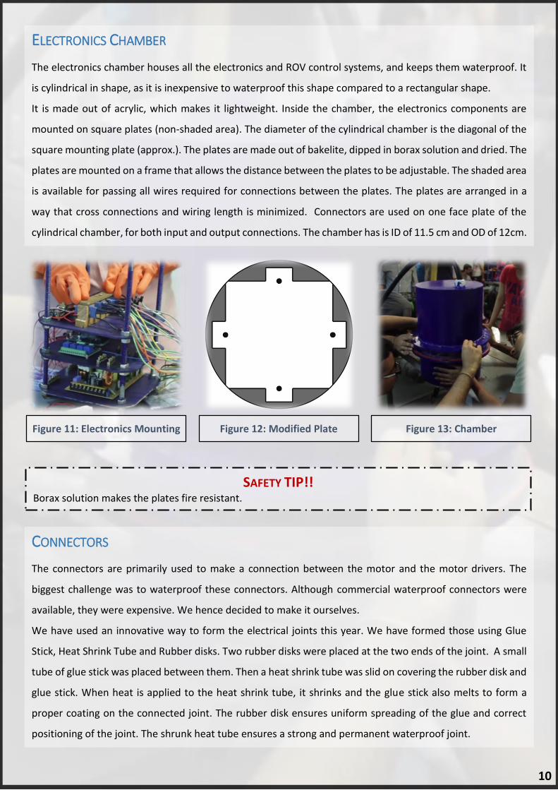
Figure 11: Electronics Mounting Figure 12: Modified Plate Figure 13: Chamber
ELECTRONICS CHAMBER
The electronics chamber houses all the electronics and ROV control systems, and keeps them waterproof. It
is cylindrical in shape, as it is inexpensive to waterproof this shape compared to a rectangular shape.
It is made out of acrylic, which makes it lightweight. Inside the chamber, the electronics components are
mounted on square plates (non-shaded area). The diameter of the cylindrical chamber is the diagonal of the
square mounting plate (approx.). The plates are made out of bakelite, dipped in borax solution and dried. The
plates are mounted on a frame that allows the distance between the plates to be adjustable. The shaded area
is available for passing all wires required for connections between the plates. The plates are arranged in a
way that cross connections and wiring length is minimized. Connectors are used on one face plate of the
cylindrical chamber, for both input and output connections. The chamber has is ID of 11.5 cm and OD of 12cm.
SAFETY TIP!! Borax solution makes the plates fire resistant.
CONNECTORS
The connectors are primarily used to make a connection between the motor and the motor drivers. The
biggest challenge was to waterproof these connectors. Although commercial waterproof connectors were
available, they were expensive. We hence decided to make it ourselves.
We have used an innovative way to form the electrical joints this year. We have formed those using Glue
Stick, Heat Shrink Tube and Rubber disks. Two rubber disks were placed at the two ends of the joint. A small
tube of glue stick was placed between them. Then a heat shrink tube was slid on covering the rubber disk and
glue stick. When heat is applied to the heat shrink tube, it shrinks and the glue stick also melts to form a
proper coating on the connected joint. The rubber disk ensures uniform spreading of the glue and correct
positioning of the joint. The shrunk heat tube ensures a strong and permanent waterproof joint.
The connectors are primarily used to make a connection between the motor and the motor drivers. The
biggest challenge was to waterproof these connectors. Although commercial waterproof connectors were
available, they were expensive. We hence decided to make it ourselves.
10

Figure 14: IMU
Figure 15: Flowmeter
SENSORS
IMU
The ROV is equipped with an Inertial Measurement Unit in the form
of GY-80 IMU. This IMU has a 3-axis Gyroscope, a 3-axis
Accelerometer, and a 3-axis Magnetometer. The combined output
from these sensors can be used to calculate the heading of the ROV
and its relative displacement from a reference position. The
reference position for this task will be the location from where the
ROV is inserted into the pool. The distance calculated from the
reference position will allow identifying at which position the iceberg
is located along with its heading. The distance can then be calculated
between the iceberg and oil rigs and subsea assets to identify which
danger zone the assets lie in.
CONDUCTIVITY SENSOR
The conductivity sensor consists of 2 metal plates connected to a
current measurement sensor, and also to an LED in parallel. This
construction will help us in checking redundancy. If one mechanism
fails, the other will help complete the tasks.
FLOW METER
The flow meter will be excluded from the ROV. The entire sensor will
be deployed into the pool separately coupled with an Arduino UNO
and a memory card to make a log of the flow rate.
ROBOTIC ARM
The robotic arm is designed in such a way that it can perform various tasks, such as attaching the lift line,
inserting a hot stab etc. It is made by 4-6 mm thick aluminium plates with three joints in it (i.e. one shoulder,
one elbow and one wrist). The entire arm is mounted on a 360 degree rotating turntable. The other 3 joints
are provided with three 180° servo motors. All motors were dismantled and waterproofed. They were then
fixed on each joint with the help of motor brackets. The clamper contains the last servo motor that will
enable the arm to hold onto objects. The total length of the robotic arm is approximately 40 cm which can
be folded by its joints so as to maintain the ROV size constraint.
For controlling the robotic arm under water, a joystick controller will be used, that will connect to a laptop
and transmit the signals to the Arduino Mega on board the ROV, via the Ethernet cable. The following
flowchart shows the working of the control of robotic arm.
11

Figure 16: Robotic Arm and it’s Algorithm
BE SAFE!! The motors were dismantled and waterproofed by marine grease which is highly efficient while working underwater. The electronics waterproofed by using a coating of Silicone.
WATERPROOFING
Waterproofing is a must when it comes to electrical equipment’s being used underwater and hence we have
employed the best possible, affordable and fool proof methods.
Instead of purchasing waterproof servo motors, we opened up the normal ones to waterproof them. Grease
helps to repel water and enables smooth functioning of gears. So we filled the internal parts of the motors
which consisted the gear mechanism also with marine grease. We put a gasket on the output shaft inside
the casing near the shaft opening to make it watertight. To ensure that there is no chance of leakage, we
sealed all the possible openings of the motor on the outer casing with silicon sealant.
For the Electronics Chamber, we have used silicon and araldite around the flange area to try and prevent
leakage through it. The holes through which the tether is supposed to enter and leave the chamber are
covered by PG Glands to ensure that water doesn’t enter, and for other waterproofing purposes, we have
used Marine grease, gaskets, silicon and araldite.
12

Figure 17: Pilot Screen Figure 18: Co-Pilot Screen
Figure 19: Sea Urchin
SOFTWARE AND ALGORITHMS
GUI
Our main GUI is built using Java, using the java fx libraries. On the surface, two monitors run this application.
The main monitor “A” displays our main camera’s feed, along with details of the thrusters, heading & specific
readings obtained from the Arduino under water (from the ROV). Screen “B” displays the remaining two
camera feeds for the co-pilot to use as reference.
This GUI also contains separate scripts made to accomplish various mission tasks. They have been written in
Python using OpenCV. These scripts run on the main screen (A) and can be used for solving tasks that require
Image Processing.
SEA URCHIN:
Collecting the sea urchin requires us to
have a better vision for the pilot, so that
he/she can “collect” a sample easily,
using the robotic arm. The program
provides a binary or threshold feed from
the camera, along with its default feed.
This helps the Pilot/Co-Pilot to better
visualize the environment.
13

Figure 20: Sea Star Count and Identification
Figure 21: Corrosion Identification
SEA STARS:
Since this task not only includes counting,
but also identification of the sea stars, we
decided to use Image Processing to count
the number of sea stars in a single frame
taken by the camera. Later, the program
automatically calculates the number, and
type (color) of the sea star. But, since color
detection under water won’t be exactly
perfect, the Pilot/ Co-Pilot has the option to
see the frame while it is being processed (to
minimize error).
CORROSION DETECTION:
Detecting of corrosion, is also automated
by the same method that was used for Sea
Urchin identification. The program
automatically searches for the threshold
value, and it is easier for the Pilot/ Co-Pilot
to detect corrosion, since two feeds are
displayed again.
The figure shows how the script can detect
the darker part of the pipe and highlight it
in the adjacent image, making carrion
detection process simpler and faster.
14

Figure 23: Finding Lengths
Figure 22: Length Algorithm
DETERMINING LENGTHS IN VARIOUS TASKS:
Determining the length of the wellhead pipe, and then
calculating the angle of inclination was a difficult task
for the team. Our software solves this task by using
simple mathematical formulas to calculate the
unknown length of the wellhead pipe, and
subsequently the angle. The software works as follows:
Pilot marks an object with a known length (on a
frame captured by the camera feed).
Pilot also marks the object with unknown
length.
Known length is the input to the software.
The software itself calculates the unknown
length, and the angle of inclination.
15

Figure 24: Algae Sample Collection
DESIGN OF SPECIAL SYSTEMS
SCIENCE UNDER THE ICE
Collecting a sample of algae from the underside of the ice sheet:
For this task we will be using a funnel whose mouth will be connected to a bilge pump. When it is powered,
it will suck the ball into a storage space, designed to ensure the sample remains in it.
Collecting an urchin located on the seafloor:
This task will be done with the help of a rod having a hook attached to it, which will lift the O- ball
representing a sea urchin.
Deploying a passive acoustic sensor in a designated area:
For this task, we will tie the acoustic sensor to the base plate of the ROV, with a special type of knot. The
robotic arm will hold one end of the knot, and pull it to release the knot and deploy the sensor in the
designated area.
SUBSEA PIPELINE INSPECTION
Conducting a CVI (close visual inspection) of an oil pipeline for corrosion:
Detection of corrosion on the pipeline would first be done using image processing (as explained in the
previous section). However, in case it fails or yields ambiguous results, an alternative method is to use the
camera mounted on robotic arm accompanied by plastic mirrors which will give a close view of underside of
the pipe for a more detailed inspection.
Turning a valve to stop the flow of oil through the pipeline:
To accomplish this task we will use a separate mechanism that is a Rotating Plate, situated at the bottom
centre of the ROV. It will freely rotate using servo motors that will turn the valves.
16

Figure 25: Base Plate + Motor + Castor Figure 26: Rotating Base Sub-Assembly
Attaching a lift line to the corroded section.
Lift line mechanism is inspired by rope callipers used by mountain climbers.
Callipers mounted on a rod will be carried by the robotic arm of the ROV. Callipers will be having air bags in
it which will give a firm grip while lifting the pipe.
Cutting (simulated) the section of corroded pipeline:
For this task the rod which was used for collecting the sea urchin will be used to pull out the U-pins from
pipes which will simulate cutting of corroded section of pipe
Removing the section of corroded pipeline and return it to the surface:
Callipers holding the pipe in position will be pulled by the lift line holder standing outside the pool.
OFFSHORE OILFIELD PRODUCTION & MAINTENANCE
Moving water through the pipeline system to verify that oil will flow through the correct pathway:
With the help of a bilge pump, water will be pumped inside the pipe.
Determining the average flow rate of the water current:
A flow rate sensor will be developed and deployed separately to gather the flow rate data of up to 5 minutes.
17
CHALLENGES
In the course of this project, we have come across many challenges, and overcoming them has given us some
valuable experience.
Budgetary Constraints: One of the biggest challenges for us was that we were falling short of funds.
Purchasing the necessary materials started becoming a difficult task. This prompted us to focus our search
efforts on Indian manufacturers only. The end result is a highly cost efficient ROV, as we saved money on
shipping, customs duty and other additional charges.
ROV Manoeuvring: As per our initial design, we were using 6 Blue Robotics T100 thrusters to manoeuvre
the ROV. However, after some initial tests, one of the thrusters stopped working. Analysing it revealed that
its motor was damaged. Ordering a new one would not only be costly, but also time consuming. Thus, an
alternate design was developed, that uses 4 of these thrusters and 4 thrusters made from bilge pumps.
Buoyancy: The initial buoyancy design made use of two plastic bottles that received air supply from a
compressor. However, upon testing it was found that the air tank of the compressor was small and didn’t fill
up the buoyancy tank fast enough. Also, the plastic bottles dented due to pressure at higher depths
underwater. Subsequently, an alternative compressor was used and PVC was chosen as the material for the
tanks.
REFERENCES
Books:
Bansal, Dr. R.K. (2012). A Textbook of Fluid Mechanics and Hydraulic Machines. New Delhi:
Laxmi Publications (P) Ltd.
Dr. Steven Moore, “Underwater Robotics – Science, Design and Fabrication”, 2010
Websites:
http://www.marinetech.org/
https://www.google.com/
www.instructables.com
www.vimeo.com
18

Figure 27: Human Capital Management
Figure 28: Risk Management
Figure 29: Design Improvements
AREAS OF IMPROVEMENT IN FUTURE
Managing excess manpower: There were an
unprecedented number of young enthusiasts who
wanted to join our team and have a great learning
experience. While we tried to take in as many of
them as we could, handling their learning and
managing the project simultaneously proved to be
cumbersome. We would want to make better use
of these inquisitive minds in the future, to ensure a
win-win situation for both.
Risk management: The procurement of Blue
Robotics T100 thrusters that we ordered from
U.S.A met with an unexpected delay. Due to this,
valuable time was lost and the project plan was
impacted. Although we did manage to recover the
lost time, it is felt that better preparedness for such
contingencies should be observed.
Design features: Our focus for this year’s ROV is
weight and easy maintenance. While we have
incorporated these to a significant extent, the
feature of compactness can also be improved
upon. Our major limitations are costly overseas
procurement and bulky nature of components
available locally.
Although we overcame most of the challenges that we faced, some areas of improvement that we should
focus on the next time we participate are:
19

Figure 30: Innovation Festival Figure 31: Adapt
OUTREACH
The zeal towards Underwater Robotics and Marine Engineering was transferred through focused outreach
activities to school students who were mentored by Team Screwdrivers to take the initiative further. In the
very first event we at Team Screwdrivers associated with a socially active chapter “ADAPT” to organize a
drawing competition and Sports Day for disabled students with the theme “Swachh Bharat” to spread
awareness about cleanliness. We continued our collaboration with Nehru Science Centre this year too.
On account of celebrating National Science Week at Nehru Science Center, an art competition called as “Sit
and draw Contest” was organized centered around science related themes. On the occasion of National
Science Day, we volunteered with Nehru Science Center to organize an education filled day for the students
present to celebrate science. The highlight was a Skype lecture given to the students by Nobel Laureate Dr.
John C. Mather, Goddard Space Flight Centre, NASA, on “From the Big Bang to Now: Observing the Universe
with the James Webb Space Telescope.”
The team conducted one of its largest outreach activities by participating in the three days long Innovation
Festival organized by Nehru Science Center. The event was graced by Padma Vibhushan Dr. Anil Kakodkar,
Chairman of the Atomic Energy Commission of India and the Secretary to the Government of India. The team
used visual aids and a working prototype of the ROV to explain the technology involved in the ROV. The team
was presented with a certificate of appreciation by Mr. Shrikant Pathak, Curator and Head Education Cell for
its efforts put thus signifying the success of the event for us.
We had a rewarding experience for themselves when we conducted outreach programs for the students
coming from all over the country. We were not only able to devise technological solutions for daily life for
different sections of the society, but also generate interest to work towards them. Through all these outreach
activities we have successfully interacted with more than 16000 people that included students, parents,
scientists and academicians.
20

ACKNOWLEDGEMENTS
First and foremost, we would like to thank Mr. Sawankumar Naik, our faculty mentor, for introducing us to
this competition and encouraging us to push our limits and aim for the sky. This project would not have been
possible without the support of our faculty members and lab assistants, who allowed us to access the various
tools and machines in the college premises. Also, a special thanks to –
MATE and Marine Technology Society ROV Committee, for organizing this year’s ROV Competition and
providing a platform to showcase our technical knowledge.
National Science Foundation, for funding this year’s international competition
SVKM NMIMS’s Mukesh Patel School of Technology Management & Engineering, for permitting us to
manufacture the ROV at their campus.
Chief Minister of Maharashtra Mr. Devendra Fadnavis, for his motivation and moral support to the team.
Country Club, for letting us use their swimming pool for testing purposes.
BlueRobotics, for providing the thrusters used in the ROV.
Mr. K.C.V Gopal Varma, who shared with us his knowledge about underwater systems and best practices
used in the industry.
Mr. Hemant Kolame, for providing tools and equipment’s required for manufacturing the ROV.
Mr. Vedant Gandhi and Adapt foundation, for their moral support to the team.
Nehru Science Center Mumbai, for letting Team Screwdrivers conduct outreach activities.
JOYO Plastics, for donating plastic household articles and corporate gifts for outreach programs.
Mr. Ramawtar Sharma and Advanced Valves, for providing funds to manufacture the ROV.
Mr. Vivek Maurya, Mr. Rajesh Bhadreshwara and Mr. Jaidev Kulkarni, for mentoring this year’s team.
Last but not the least; we would like to thank our family members, friends and junior volunteers of the team,
for giving us their support and good wishes.
21

AS OF MAY 2015 COMPONENT TYPE UNIT COST ($.) TOTAL ($)
CONTROL SYSTEM
Controller DONATED 45 90
Tether NEW 33 33
Ethernet cables USED 7
ELECTRONICS
DC-DC Converters - 12 V NEW 161 483
DC-DC Converters - 5 V NEW 83 83
Arduino Mega NEW 58 117
Ethernet Shield USED 16 32
Relay Board NEW 2 2
Motor Driver USED 12 36
Servo Motors NEW 13 78
ESC NEW 13 80
Thrusters NEW 111 667
Bilge pumps USED 20 80
Cameras NEW 111 333
EC Chamber NEW 250 250
PNEUMATICS
Buoyancy tanks NEW 17 17
Compressor DONATED 83 83
Valves NEW 6 12
Regulator NEW 10 10
WATERPROOFING
Araldite NEW 5 15
Marine grease NEW 12 12
Silicon gun NEW 8 8
Glue gun NEW 3.3 3.3
Glue sticks NEW 0.13 2.6
SAFETY EQUIPMENT
Fuses NEW 0.28 8
Rubber gloves NEW 1.2 20
Safety goggles NEW 1.6 28
Insulating tape NEW 0.17 3
Lab apron DONATED 1.7 33
MISC.
Arduino Connectors USED 0.2 7
Wires USED 8
Heat gun USED 67 67
Hand grinder USED 83 83
Chassis manufacturing NEW 167 167
TRAVEL Lodging 360 5400
Team Travel 1600 24000
TOTAL WITHOUT TRAVELLING EXPENSES (NEW Items) 2431.9
APPENDIX A: BUDGET
22

APPENDIX B: SAFETY CHECKLIST
Before beginning work on the ROV:
Remove any rings, watches or jewellery.
Wearing closed shoes and lab apron is a must. Safety glasses and gloves need to be worn when working
with machines and chemicals.
Long hair should be tightly secured.
Keep a first aid kit handy at all times.
Ensure juniors are supervised by a senior team member at all times.
Before turning on power supply:
Always attach a fuse of proper rating while testing any equipment.
Make sure all connections are tight and insulated.
Ask a third person to check if connections are correct to avoid biasing error.
Before putting the ROV in water:
Check if the electronics chamber is tightly secured.
Ensure waterproof glands are tightly secured.
Ensure all components are in place.
Check if main fuse is intact.
When ROV is in water:
During testing, pilot will say “We are live” before he begins to maneuver the ROV.
When the ROV is in water, members inside the pool must observe it from a safe distance.
Members in the pool should specifically stay away from parts painted with yellow and black stripes.
In case anything is amiss the pilot must immediately bring the ROV to surface and shout “Mission
Aborted” to indicate that it is safe to handle the ROV now.
After removing the ROV from water:
Once the ROV is on the deck, the power supply will be turned off and the tether will be unplugged by a
member with dry hands.
All members who were in the pool will not be allowed near the ROV once the electronics chamber is
opened.
23

Figure 32: Deck ROV Figure 32: ROV Deck
APPENDIX C: SOFTWARE FLOWCHARTS
24