Table of contents • with integrated 3-way ball valve type ... · 104 105 Ball valve-function...
14
Transcript of Table of contents • with integrated 3-way ball valve type ... · 104 105 Ball valve-function...


3
Ball valve-combinations 105
• Shut-off blocks with integrated bypass and safety-lock 106
• Sandwich plates 108
• Accumulator safety blocks 114
• with integrated 2-way ball valve type RSA 114
• with integrated 3-way ball valve type RSK 120
• with integrated 3-way ball valve type RSM 124
Tabl
e of
con
tent
s

105104 105 104
Ball valve-function systems
Sandwich plates Accumulator safety blocks
Shut-off blocks with integrated bypass and safety-lock
Pro
duct
ove
rvie
w

107106
Shut-off blocks with integrated bypass and safety-lock
For cut (clamp) ring tube fittings DIN 2353 heavy series ISO 8434-1
NPT-female thread ANSI/ASME B1.20.1-1983
Body: steel, black oxideBall: steel, hard chrome platedStem: steel, zinc platedBall seals: POMStem seals: NBR
Handle included in delivery
For handles refer to "Attachments, accessories".
Please check pressure ratings of pipe fittings!
Also available with most other connections
Custom orders on request
All dimensions subject to change without notice
Dimensions in mm
Weight in kg
Pressure in bar
Shut-off blocks · steel · DN 10 - DN 25
Type of connection DN Thread OD L L1 L2 L3 L4 L5 L6 B B1 B2 B3 H H1 H2 D1 D2 T SW SW1 HandleWeight PN Article-No. D Code 10 M18 x 1,5 12 120 11 90 51,0 22,8 60 6,5 90 20,7 45,7 70,7 40 19,5 43,5 8,4 15 9 24 8 13 1,9 500 250 001 12 M22 x 1,5 15 132 12 100 53,0 23,5 80 9,5 100 17,0 46,5 76,0 46 23,0 49,5 10,5 17 11 30 10 14 3,2 500 250 002 20 M30 x 2 22 149 14 110 66,5 29,0 90 12,0 125 23,0 60,0 97,0 62 31,0 68,5 10,5 17 11 41 14 15 5,5 400 250 004 25 M36 x 2 28 173 14 135 76,6 32,6 115 6,5 147 27,8 71,8 115,8 68 34,0 74,5 10,5 17 11 50 14 15 8,3 400 250 005
10 M22 x 1,5 14 126 14 90 51,0 22,8 60 6,5 90 20,7 45,7 70,7 40 19,5 43,5 8,4 15 9 24 8 13 1,9 500 250 006 12 M24 x 1,5 16 136 14 100 53,0 23,5 80 9,5 100 17,0 46,5 76,0 46 23,0 49,5 10,5 17 11 30 10 14 3,2 500 250 007 20 M36 x 2 25 157 18 110 66,5 29,0 90 12,0 125 23,0 60,0 97,0 62 31,0 68,5 10,5 17 11 41 14 15 5,5 400 250 009 25 M42 x 2 30 185 20 135 76,6 32,6 115 6,5 147 27,8 71,8 115,8 68 34,0 74,5 10,5 17 11 50 14 15 8,3 400 250 010
10 G 3/8 - 118 14 90 51,0 22,8 60 6,5 90 20,7 45,7 70,7 40 19,5 43,5 8,4 15 9 24 8 13 1,9 500 250 011 12 G 1/2 - 131 15 100 53,0 23,5 80 9,5 100 17,0 46,5 76,0 46 23,0 49,5 10,5 17 11 30 10 14 3,2 500 250 012 20 G 3/4 - 143 18 110 66,5 29,0 90 12,0 125 23,0 60,0 97,0 62 31,0 68,5 10,5 17 11 41 14 15 5,5 400 250 014 25 G 1 - 178 18 135 76,6 32,6 115 6,5 147 27,8 71,8 115,8 68 34,0 74,5 10,5 17 11 50 14 15 8,3 400 250 015
10 3/8 -18 NPT - 118 10,3 90 51,0 22,8 60 6,5 90 20,7 45,7 70,7 40 19,5 43,5 8,4 15 9 24 8 13 1,9 500 250 016 12 1/2 -14 NPT - 131 13,6 100 53,0 23,5 80 9,5 100 17,0 46,5 76,0 46 23,0 49,5 10,5 17 11 30 10 14 3,2 500 250 017 20 3/4 -14 NPT - 143 14,1 110 66,5 29,0 90 12,0 125 23,0 60,0 97,0 62 31,0 68,5 10,5 17 11 41 14 15 5,5 400 250 018 25 1 -111/2 NPT - 178 16,8 135 76,6 32,6 115 6,5 147 27,8 71,8 115,8 68 34,0 74,5 10,5 17 11 50 14 15 8,3 400 250 019
Shut-off blocks · technical information
Ball valve-function systems
For cut (clamp) ring tube fittings DIN 2353 light series ISO 8434-1
BSP-female thread DIN EN ISO 228-1
Application/function:For liquid and oily media as per the compatibility table in the technical data appendix; for insertion upline of actua-tor cylinders with the capability to both block the cylinder feed lines and to short-circuit them.
The previous situation: Installation of seperate ball valves in the piping system. Here a total of twelve pipe joints must be provided, using two tees. This is labor-intensive and thus expensive. In addition, the hazard of leaks rises with the number of joints.
Our solution for the problem:Combining the three shut-off func-tions within a single block by incor-porating three ball valve assemblies. Only four pipe connections need to be made. A certain sequence in operation is achieved by cam inter-locks on the ball valves:
1. block the rod end
2. open the bypass
3. block the piston end
Advantages:- clear design and user-friendly arrangement- quick assembly with a reduced number of pipe connections- reduced hazard of leaks- mutual interlocks for the valves give a specific operating sequence and prevent any pressure intensification in the rod end of the cylinder- switches can be attached

109108
Ball valve-function systems
Sandwich plates · technical information Sandwich plates · NG 6 · PN 315
31,7
531
,75
31 25,9
25,9 15
,515
,515
,5
5,1
5,1
0,75
0,75
40,540,5
30,230,2
21,21,5
12,12,12,7
48
8,5
8,5
13
74,574,5
66,66,5
A
B
TTT
13,6
13,6
13,6
13,6
10
48,2
48,2
16,8
16,8
16,8
9
M5
M5
48,2
48,2
67.5
P
BA
RALA
LA RA
emp
f. E
insc
hrau
blä
nge
10 b
is 1
5
48
A : Arbeitsanschluß
P : DruckanschlußT : TankanschlußT : TankanschlußT : T
B : Arbeitsanschluß
P
SW7 SW7
SW7
The previous situation:
The large number of control elements means large systems susceptible to malfunctions. If, for example, a solenoid valve at the central hydraulic system for an aluminium rolling mill failed, the controlled component would have to be operated manually or production would have to be suspended to change the valve.
This replacement makes it necessary to depressurize the system, to prop up external loads which cylinders are supporting and to drain the fluid from the riser lines to the cylinder. Once the solenoid valve has been changed, the lines will have to be refilled and bled.
Our solution for the problem:
With the use of our sandwich-plate, which is bolted seperately to the con-trol block, all the channels through the plate can be blocked and the direc-tional-control valve can be replaced without having to depressurize or drain lines and without affecting the other control units on the same block. All channels are open during normal operation. The operating handle can be removed to prevent unauthorized actuation.
Advantages:
- full bore design causes no pressure drop
- significant reduction in hydraulic system downtime
- no need to drain fluid, bleed air or refill the system
- simplified start-up and maintenance due to the ease of changing flushing plates and directional valves
- pressure can be maintained in cylinders so that the supported loads do not need to be shored up
- standard mounting and porting patterns allow retrofit without rework
- proprietary design increases safety by utilizing separate mechanically isolated bolts for mounting the sandwich-plate and directional valve; removing the directional valve cannot accidentally loosen the sandwich-plate
Applications:
For liquid media as per the compatibility table in the technical data appendix
On request: Limit switch, proximity switch, locking devices; also available in other mate-rials and combinations
Shut-off plates and sandwich elements for interconnected systems
Repair setting:Passages inside the sandwich plateshut-off; plate remains bolted to the hydraulic control block. Solenoid valve removed.
Operation setting:Sandwich plate with the solenoid valve mounted on top
Article-No. 208 030
Weight: 1,55 kgOpening pressure of check valve: approx. 0,3 barDrilling pattern to DIN 24340-A6 and ISO 4401-03-02-0-94Custom orders on request All dimensions subject to change without noticeAlso available with blocking in A and B only Dimension sheet on request, locking device retrofittable
A: working connection
B: working connection
P: pressure connection
T: reservoir connection
reco
mm
end
ed t
hrea
d e
ngag
emen
t
10 t
o 15
RV
RVLV
LV

111110
Sandwich plates · NG 10 · PN 315 46
32,5 21
,4
50,8
3,216,7
2737,3
18,5
70106,591
RALA 6,3
12
B : Arbeitsanschluß
T : TankanschlußP : Druckanschluß
A : Arbeitsanschluß
T
A
B
1511
M6
63,6
21,4 12
,5
M6
63,6
99,5
70
P
BA
RALA 12 b
is 1
5em
pf.
Ein
schr
aub
län g
e
P
54*) : Blindabdichtung für evtl.
*)
zusätzlichen Tankanschluß
SW8SW8
SW8
Sandwich plates · NG 16 · PN 315
Ball valve-function systems
Article-No. 208 032
Weight: 4,45 kgOpening pressure of check valve: approx. 0,3 barDrilling pattern to DIN 24340-A10 and ISO 4401-05-04-0-94Custom orders on request All dimensions subject to change without noticeAlso available with blocking in A and B only Dimension sheet on request, locking device retrofittable
A: working connection
B: working connection
P: pressure connection
T: reservoir connection
*): blind sealing for potential
additional tank connection
reco
mm
end
ed
thre
ad e
ngag
emen
t
RV RV
RVLVRVLV
LV LV
Article-No. 208 034
Weight: 11,7 kgOpening pressure of check valve: approx. 0,3 barDrilling pattern to DIN 24340-A16 and ISO 4401-07-06-0-94Custom orders on request All dimensions subject to change without noticeAlso available with blocking in A and B only Dimension sheet on request, locking device retrofittable
12 to
15
A: working connection
B: working connection
P: pressure connection
T: reservoir connection
L: leak connection
X: pilot connection
Y: pilot connection
reco
mm
end
ed
thre
ad e
ngag
emen
t
20 to
25
113112
Sandwich plates · NG 25 · PN 315 Article-No. 208 036
Weight: 25,4 kgOpening pressure of check valve: approx. 0,3 barDrilling pattern to DIN 24340-A25 and ISO 4401-08-07-0-94Custom orders on request All dimensions subject to change without noticeAlso available with blocking in A and B only Dimension sheet on request, locking device retrofittable
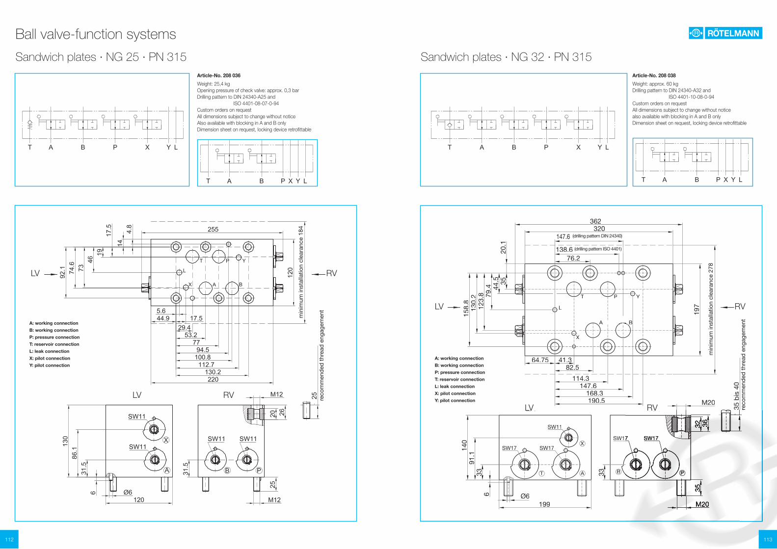
Sandwich plates · NG 32 · PN 315 Article-No. 208 038
Weight: approx. 60 kgDrilling pattern to DIN 24340-A32 and ISO 4401-10-08-0-94Custom orders on request All dimensions subject to change without noticealso available with blocking in A and B only Dimension sheet on request, locking device retrofittable
138.6 (Lochbild ISO 4401)(Lochbild ISO 4401)
147.6 (Lochbild DIN 24340)147.6 (Lochbild DIN 24340)320
362
197
Min
des
t-E
inb
aub
reite
278
3544
.579
.412
3.8
130.
215
8.8
20.1
41.3
76.2
82.582.5
114.3147.6
168.3190.5
64.75
RARALAM20
Ø6199
6
140
3391
.1AAT
XX
B P33
M20
353632
35 b
is 4
0
T P Y
A BA BA BA B
X
L
emp
f. E
insc
hrau
blä
nge
emp
f. E
insc
hrau
blä
nge
RALA
Y : SteueranschlußX : SteueranschlußL : Leckanschluß
B : Arbeitsanschluß
T : TankanschlußT : TankanschlußT : TP : Druckanschluß
A : Arbeitsanschluß
SW11
SW17SW17
SW17SW17 SW17
Ball valve-function systems
A: working connection
B: working connection
P: pressure connection
T: reservoir connection
L: leak connection
X: pilot connection
Y: pilot connection
reco
mm
end
ed t
hrea
d e
ngag
emen
t
min
imum
inst
alla
tion
clea
ranc
e 18
4
A: working connection
B: working connection
P: pressure connection
T: reservoir connection
L: leak connection
X: pilot connection
Y: pilot connection
reco
mm
end
ed t
hrea
d e
ngag
emen
t
min
imum
inst
alla
tion
clea
ranc
e 27
8
(drilling pattern DIN 24340)
(drilling pattern ISO 4401)
RV
RV
RV
RV
LV
LV
LV
LV

115114
Accumulator safety blocks · with integrated 2-way ball valve type RSA
Ball valve-function systems
Fig. D1 Connection- Adapter- K L1 L2 D2 O-Ring thread fitting (SW)
G 3/4 A S010 41 28 43,5 - 17 x 31 G 1 A S011 46 34 50,5 - 22 x 3 G 11/4 A S012 46 37 53,5 - 30 x 3 G 2 A S013 65 44 64,5 - 48 x 3 M 30 x 1,5 S020 41 15 32,5 40 32 x 22 M 40 x 1,5 S021 55 20 40,5 54 43 x 3 M 50 x 1,5 S022 65 20 40,5 64 53 x 3
Abb. 1 Abb. 2
NG 10
Technical informationAccumulator safety blocks · with integrated 2-way ball valve type RSA
H
DBV
TP
S
M1M2
SV
V
9858
22.5
7129
47
53.55029.5
22.8 11024
35
53
M2
T
M1
P
S
manuelle EntlastungS
P
M1
T
M2
zusätzlicheelektromagnetische Entlastung
Securing, isolating and depressurising hydraulic pressure accumulators: Simple operation stands for absolute operational safety. Depending on the position of the handle, the passage from the system to the accumulator will be opened or closed. The accumulator block can be kept pressurised with the valve in the closed status (battery configuration). The accumulator can be relieved manually with the integrated valve. - Refer to "3-way accumulator safety blocks" if automatic relief is desired.
Flexibility thanks to a modular design: The modular design concept makes the safety block particularly economical and flexible to meet customer requirements. The body is assembled at the factory with adapter fittings in accordance with your order.
Applications/functions:For liquid media as per the compatibility table in the technical data appendixThe accumulator safety blocks can be supplied with solenoid-operated relief valves if desired. Every block is equipped with the connections required for retrofitting.
All dimensions subject to change without notice
Manual relief Additional electromagnetical relief
Locking device available
Easy orde guide: RSA 10 F F S010 1 1 N 300 E Y 1Nominal size (NG) ball valve10 = NG 1020 = NG 20 32 = NG 32 Connection thread pump (P)A = M22x1.5 light series (ISO 8434-1)B = M36x2 light series (ISO 8434-1)C = M52x2 light series (ISO 8434-1)D = M24x1.5 heavy series (ISO 8434-1)E = M42x2 heavy series (ISO 8434-1)F = G 1/2 (DIN EN ISO 228-1)G = G1 (DIN EN ISO 228-1)H = G11/2 (DIN EN ISO 228-1)J = 1/2-14NPT (ANSI/ASME B1.20.1-1983)K = 1-111/2NPT (ANSI/ASME B1.20.1-1983)L = 11/2-111/2NPT (ANSI/ASME B1.20.1-1983)M = other threadsConnection thread tank (T)A = M22x1.5 light series (ISO 8434-1)B = M36x2 light series (ISO 8434-1)C = M52x2 light series (ISO 8434-1)D = M24x1.5 heavy series (ISO 8434-1)E = M42x2 heavy series (ISO 8434-1)F = G 1/2 (DIN EN ISO 228-1)G = G1 (DIN EN ISO 228-1)H = G11/2 (DIN EN ISO 228-1)J = 1/2-14NPT (ANSI/ASME B1.20.1-1983)K = 1-111/2NPT (ANSI/ASME B1.20.1-1983)L = 11/2-111/2NPT (ANSI/ASME B1.20.1-1983)M = other threadsAdapter fitting for accumulator (S)e.g. S010 = G 3/4A (DIN EN ISO 228 – 1) refer to tableBody material1 = Steel4 = other materialSealing material (elastomer)1 = NBR 2 = FKM3 = EPDM5 = other materialPressure relief valve (DBV)N = without approvalT = with TÜV-approvalX = Delivered without pressure limiter valve opening pressure 300 = e.g. 300 bar 000 = Delivered without pressure limiter valveReliefM = manualE = manual and electromagneticV = prepared for electromagnetical reliefSolenoid valve designX = Delivered without solenoid valve Y = open when de-energizedZ = closed when de-energizedSolenoid valve voltage0 = Delivered without solenoid valve1 = 24 V DC2 = 230 V DC3 = other
Fig. 1 Fig. 2
Also available with most other connections
Adapter fittings for accumulator connection S
P = Pump connection M-version 400 bar E-version 350 barT = Tank connectionS = Accumulator connectionM1 = Test gauge connection G1/4 (DIN EN ISO 228-1)M2 = Pressure gauge connection (closed) G1/4 (DIN EN ISO 228-1)DBV = Pressure relief valve cavity-thread M28x1.5 assembly torque 50+5 NmSV = 2-way-solenoid valve cavity-thread M20x1.5 assembly torque 25+5 Nm (manual relief closed)V = Pressure reliefH = Handle Code 13 (8kt8) refer to chapter "Attachments, accessories"

117116
Accumulator safety blocks · with integrated 2-way ball valve type RSA
Ball valve-function systems
NG 32
Fig. D1 Connection- Adapter- L1 L2 D2 O-Ring thread fitting
G 3/4 A S305 28 58 - 17 x 3 1 G 1 A S306 34 64 - 22 x 3 G 11/4 A S307 37 67 - 30 x 3 G 2 A S309 44 74 - 48 x 3
M 30 x 1,5 S330 15 47 45 32 x 22 M 40 x 1,5 S340 20 51 60 43 x 3 M 50 x 1,5 S350 20 51 75 53 x 3
L2
L1
O-Ring
D1
Ø105 (4 Bohrungen)
O-Ring 37,2 x 3
100Fig. 1 Fig. 2
NG 20
Abb. D1 Connection- Adapter- K L1 L2 D2 O-Ring thread fitting (SW)
G 3/4 A S010 41 28 43,5 - 17 x 31 G 1 A S011 46 34 50,5 - 22 x 3 G 11/4 A S012 46 37 53,5 - 30 x 3 G 2 A S013 65 44 64,5 - 48 x 3
M 30 x 1,5 S020 41 15 32,5 40 32 x 22 M 40 x 1,5 S021 55 20 40,5 54 43 x 3 M 50 x 1,5 S022 65 20 40,5 64 53 x 3
2,5
19
L 2L1
O-Ring29,7 x 2,8
O-Ring
D1
K
Ø38M33 x 2
Ø38
2,5
19
L2L1
O-Ring29,7 x 2,8
O-RingD1
KD2
M33 x 2Fig. 1 Fig. 2
L2
D2
L1
O-RingD1
Ø105 (4 Bohrungen)
O-Ring 37,2 x 3
100
DBV
VT
M1
SVM2
S
P
H
25100
8853
120
58.5
30
82
397074
8853
15
Accumulator safety blocks · with integrated 2-way ball valve type RSA
M2
T
M1
P
S
manuelle Entlastung
M2
T
M1
P
S
manuelle EntlastungS
P
M1
T
M2
zusätzlicheelektromagnetische Entlastung
S
P
M1
T
M2
zusätzlicheelektromagnetische Entlastung Manual relief
Additional electromagnetical reliefManual relief
Additional electromagnetical relief
All dimensions subject to change without notice
All dimensions subject to change without notice
Also available with most other connectionsAlso available with most other connections
Adapter fittings for accumulator connection SAdapter fittings for accumulator connection S
(4 bores) (4 bores)
P = Pumpconnection M-version 400 bar E-version 350 barT = Tank connectionS = AccumulatorconnectionM1 = Testgaugeconnection G1/2 (DIN EN ISO 228-1)M2 = Pressuregaugeconnection(closed) G1/4 (DIN EN ISO 228-1)DBV= Pressurereliefvalve cavity-thread M35x1.5 assembly torque 80+5 NmSV = 2-way-solenoidvalve cavity-thread M20x1.5 assembly torque 25+5 Nm (manual relief closed)V = Pressure reliefH = Handle Code 21(8kt17) refer to chapter "Attachments, accessories"
P = Pump connection M-version 400 bar E-version 350 barT = Tank connectionS = Accumulator connection G1/2 (DIN EN ISO 228-1)M2 = Pressure gauge connection (closed) G1/4 (DIN EN ISO 228-1)DBV = Pressure relief valve cavity-thread M35x1.5 assembly torque 80+5 NmSV = 2-way-solenoid valve cavity-thread M20x1.5 assembly torque 25+5 Nm (manual relief closed) V = Pressure reliefH = Handle Code 15(8kt14) refer to chapter "Attachments, accessories"

119118
Accumulator safety blocks · with integrated 2-way ball valve type RSA
Ball valve-function systems
NG 32
P = Pumpconnection DN 38 ISO 6162-2 (UNC) DN 51 ISO 6162-1 (UNC) M-version 350 bar E-version 350 barT = Tankconnection 3/4 - 16 UNF-2BS = Accumulatorconnection DN 38 ISO 6162-2 (UNC) DN 51 ISO 6162-1 (UNC)M = Testgaugeconnection 1/4 - 18 NPTDBV= Pressurereliefvalve cavity-thread M16x1.5 assembly torque 35+5 NmSV = 2-way-solenoidvalve cavity-thread M20x1.5 assembly torque 45+5 Nm (manual relief closed)V = PressurereliefH = HandhebelCode21(8kt17) refer to chapter "Attachments, accessories"
Accumulator safety blocks · with integrated 2-way ball valve type RSA
P = Pump connector DN 38 ISO 6162-2 (metric) DN 51 ISO 6162-1 (metric) M-version 350 bar E-version 350 barT = Tank connector 3/4 - 16 UNF-2BS = Accumulator connector DN 38 ISO 6162-2 (metric) DN 51 ISO 6162-1 (metric)M = Test gauge connection 1/4 - 18 NPTDBV= Pressure relief valve cavity-thread M16x1.5 assembly torque 35+5 NmSV = 2-way Solenoid cavity-thread M20x1.5 assembly torque 45+5 Nm (manual relief closed)V = Pressure reliefH = Handle Code21(8kt17) refer to chapter "Attachments, accessories"
NG 32
T
M
P
S
manuelle Entlastung
S
P
M
T
zusätzlicheelektromagnetische Entlastung
T
M
P
S
manuelle Entlastung
S
P
M
T
zusätzlicheelektromagnetische Entlastung
104.
5M
TSV
P
V
S
P
DBV
M12DN51 ISO 6162-1
M16DN38 ISO 6162-2
100
5050
24
77
31
165
52 20
74
25
48
187 100
104.
5
V
PS
TSV
M
P
5/8-11 UNCDN38 ISO 6162-2
1/2-13UNCDN51 ISO 6162-1
48
187 100
50
100
50
31
165
52 20
77
24
74
25
DBV
Manual relief Additional electromagnetical reliefManual relief
Additional electromagnetical relief
All dimensions subject to change without notice
All dimensions subject to change without notice
121120
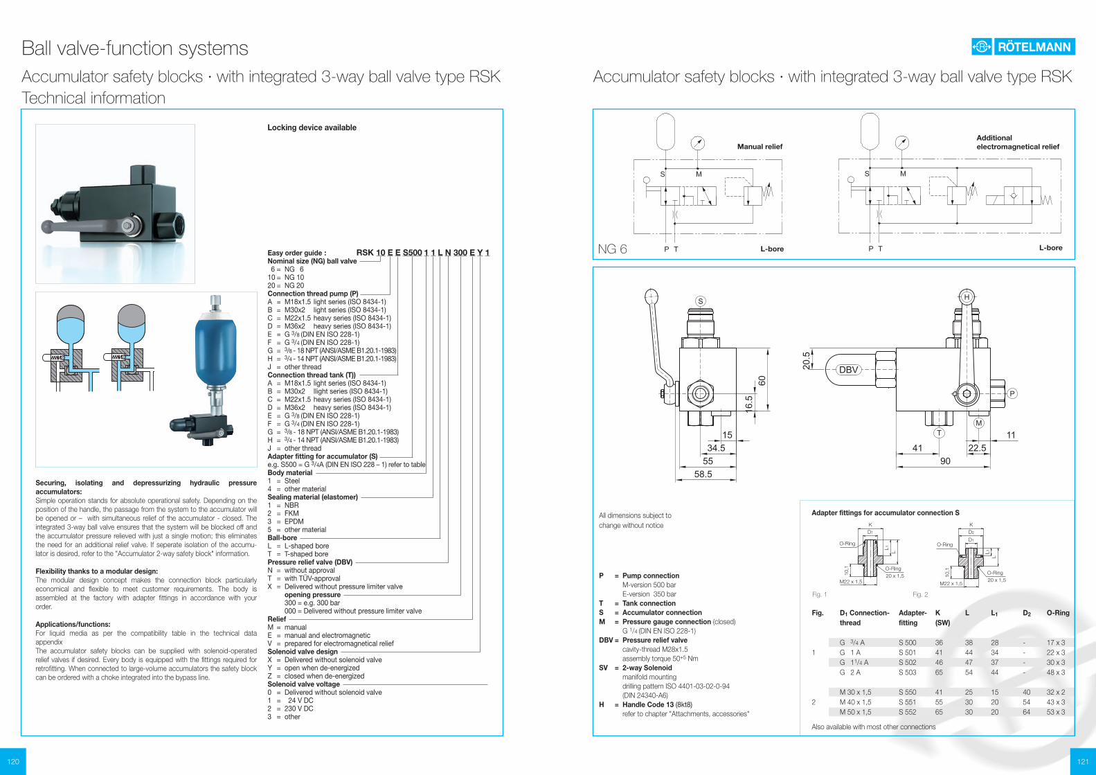
Accumulator safety blocks · with integrated 3-way ball valve type RSK
Ball valve-function systems
NG 6
P = Pump connection M-version 500 bar E-version 350 barT = Tank connectionS = Accumulator connectionM = Pressure gauge connection (closed) G 1/4 (DIN EN ISO 228-1)DBV = Pressure relief valve cavity-thread M28x1.5 assembly torque 50+5 NmSV = 2-way Solenoid manifold mounting drilling pattern ISO 4401-03-02-0-94 (DIN 24340-A6)H = Handle Code 13 (8kt8) refer to chapter "Attachments, accessories"
Fig. D1Connection- Adapter- K L L1 D2 O-Ring thread fitting (SW)
G 3/4 A S 500 36 38 28 - 17 x 31 G 1 A S 501 41 44 34 - 22 x 3 G 11/4 A S 502 46 47 37 - 30 x 3 G 2 A S 503 65 54 44 - 48 x 3
M 30 x 1,5 S 550 41 25 15 40 32 x 22 M 40 x 1,5 S 551 55 30 20 54 43 x 3 M 50 x 1,5 S 552 65 30 20 64 53 x 3
10,1
LL 1
O-Ring20 x 1,5
O-Ring
D1
K
M22 x 1,5
10,1
LL 1
O-Ring20 x 1,5
O-RingD1
KD2
M22 x 1,5
Fig. 1 Fig. 2
Technical informationAccumulator safety blocks · with integrated 3-way ball valve type RSK
DBV
S
TM
P
H
9041
11
6016.5
5534.5
1522.5
20.5
58.5
Manual relief Additional electromagnetical relief
L-bore L-bore
All dimensions subject to change without notice
Also available with most other connections
Easy order guide : RSK 10 E E S500 1 1 L N 300 E Y 1Nominal size (NG) ball valve 6 = NG 610 = NG 1020 = NG 20Connection thread pump (P)A = M18x1.5 light series (ISO 8434-1)B = M30x2 light series (ISO 8434-1)C = M22x1.5 heavy series (ISO 8434-1)D = M36x2 heavy series (ISO 8434-1)E = G 3/8 (DIN EN ISO 228-1)F = G 3/4 (DIN EN ISO 228-1)G = 3/8 - 18 NPT (ANSI/ASME B1.20.1-1983)H = 3/4 - 14 NPT (ANSI/ASME B1.20.1-1983)J = other threadConnection thread tank (T))A = M18x1.5 light series (ISO 8434-1)B = M30x2 llight series (ISO 8434-1)C = M22x1.5 heavy series (ISO 8434-1)D = M36x2 heavy series (ISO 8434-1)E = G 3/8 (DIN EN ISO 228-1)F = G 3/4 (DIN EN ISO 228-1)G = 3/8 - 18 NPT (ANSI/ASME B1.20.1-1983)H = 3/4 - 14 NPT (ANSI/ASME B1.20.1-1983)J = other threadAdapter fitting for accumulator (S)e.g. S500 = G 3/4A (DIN EN ISO 228 – 1) refer to tableBody material1 = Steel4 = other materialSealing material (elastomer)1 = NBR 2 = FKM3 = EPDM5 = other materialBall-boreL = L-shaped boreT = T-shaped borePressure relief valve (DBV)N = without approvalT = with TÜV-approvalX = Delivered without pressure limiter valve opening pressure 300 = e.g. 300 bar 000 = Delivered without pressure limiter valveReliefM = manualE = manual and electromagneticV = prepared for electromagnetical reliefSolenoid valve designX = Delivered without solenoid valve Y = open when de-energizedZ = closed when de-energizedSolenoid valve voltage0 = Delivered without solenoid valve1 = 24 V DC2 = 230 V DC3 = other
Locking device available
Securing, isolating and depressurizing hydraulic pressure accumulators: Simple operation stands for absolute operational safety. Depending on the position of the handle, the passage from the system to the accumulator will be opened or – with simultaneous relief of the accumulator - closed. The integrated 3-way ball valve ensures that the system will be blocked off and the accumulator pressure relieved with just a single motion; this eliminates the need for an additional relief valve. If seperate isolation of the accumu-lator is desired, refer to the "Accumulator 2-way safety block" information.
Flexibility thanks to a modular design: The modular design concept makes the connection block particularly economical and flexible to meet customer requirements. The body is assembled at the factory with adapter fittings in accordance with your order.
Applications/functions:For liquid media as per the compatibility table in the technical data appendixThe accumulator safety blocks can be supplied with solenoid-operated relief valves if desired. Every body is equipped with the fittings required for retrofitting. When connected to large-volume accumulators the safety block can be ordered with a choke integrated into the bypass line.
Adapter fittings for accumulator connection S

123122
Ball valve-function systems
NG 20
Fig. D1Connection- Adapter- K L L1 D2 O-Ring thread fitting (SW)
G 3/4 A S 600 41 38 28 - 17 x 31 G 1 A S 601 41 44 34 - 22 x 3 G 11/4 A S 602 46 47 37 - 30 x 3 G 2 A S 603 65 54 44 - 48 x 3
M 30 x 1,5 S 650 41 25 15 40 32 x 22 M 40 x 1,5 S 651 55 30 20 54 43 x 3 M 50 x 1,5 S 652 65 30 20 64 53 x 3
13
LL 1
O-Ring34 x 2
O-Ring
D1
K
M36 x 1,5
13
LL 1
O-Ring34 x 2
O-RingD1
KD2
M36 x 1,5
Fig. 1 Fig. 2
Accumulator safety blocks · with integrated 3-way ball valve type RSK
NG 10
Fig. D1Connection- Adapter- K L L1 D2 O-Ring thread fitting (SW)
G 3/4 A S 500 36 38 28 - 17 x 31 G 1 A S 501 41 44 34 - 22 x 3 G 11/4 A S 502 46 47 37 - 30 x 3 G 2 A S 503 65 54 44 - 48 x 3
M 30 x 1,5 S 550 41 25 15 40 32 x 22 M 40 x 1,5 S 551 55 30 20 54 43 x 3 M 50 x 1,5 S 552 65 30 20 64 53 x 3
Fig. 1 Fig. 2
10,1
LL1
O-Ring20 x 1,5
O-Ring
D1
K
M22 x 1,5
10,1
LL 1
O-Ring20 x 1,5
O-RingD1
KD2
M22 x 1,5
P = Pumpconnection M-version 500 bar E-version 350 barT = TankconnectionS = AccumulatorconnectionM = Pressuregaugeconnection (closed) G 1/4 (DIN EN ISO 228-1)DBV= Pressurereliefvalve cavity-thread M35x1.5 assembly torque 80+5 NmSV = 2-way-solenoidvalve manifold mounting drilling pattern ISO 4401-03-02-0-94 (DIN 24340-A6)H = HandleCode13(8kt8) refer to chapter "Attachments, accessories"
EV = Pressurereliefvalve (selectively manualy electromagnetic)P = Pumpconnection M-version 315 bar E-version 315 barT = TankconnectionS = AccumulatorconnectionM = Pressuregaugeconnection(closed) G 1/4 (DIN EN ISO 228-1)DBV= Pressurereliefvalve cavity-thread M35x1.5 assembly torque 80+5 NmSV = 2-way-solenoidvalve manifold mounting drilling pattern ISO 4401-03-02-0-94 (DIN 24340-A6)H = HandleCode15(8kt14) refer to chapter "Attachments, accessories"
Accumulator safety blocks · with integrated 3-way ball valve type RSK
S
DBV
H
P
M
T
T100
3518
7039 41
100
30.212
97.5
18
33.5
22.5
27.5
74
DBV
S
TM
P
H
9041
11
6016.5
5534.5
1522.5
20.5
58.5
Manual relief Additional electromagnetical reliefManual relief
Additional electromagnetical relief
L-boreL-bore L-boreL-bore
All dimensions subject to change without notice
All dimensions subject to change without notice
Adapter fittings for accumulator connection SAdapter fittings for accumulator connection S
Also available with most other connectionsAlso available with most other connections

125124
Accumulator safety blocks · with integrated 3-way ball valve type RSM
Ball valve-function systems
NG 10
P = Pump connection M-version 400 bar E-version 350 barT = TankconnectionS = AccumulatorconnectionM1 = Testgaugeconnection G 1/4 (DIN EN ISO 228-1)M2 = Pressuregaugeconnection (closed) G 1/4 (DIN EN ISO 228-1)DBV= Pressurereliefvalve cavity-thread M28x1.5 assembly torque 50+5 NmSV = 2-way-solenoidvalve cavity-thread M20x1.5 assembly torque 25+5 NmH = HandleCode15(8kt14) refer to chapter "Attachments, accessories"
Fig. D1Connection- Adapter- K L L1 D2 O-Ring thread fitting (SW)
G 3/4 A S 500 36 38 28 - 17 x 31 G 1 A S 501 41 44 34 - 22 x 3 G 11/4 A S 502 46 47 37 - 30 x 3 G 2 A S 503 65 54 44 - 48 x 3
M 30 x 1,5 S 550 41 25 15 40 32 x 22 M 40 x 1,5 S 551 55 30 20 54 43 x 3 M 50 x 1,5 S 552 65 30 20 64 53 x 3
10,1
LL 1
O-Ring20 x 1,5
O-Ring
D1
K
M22 x 1,5
10,1
LL 1
O-Ring20 x 1,5
O-RingD1
KD2
M22 x 1,5
Fig. 1 Fig. 2
Technical informationAccumulator safety blocks · with integrated 3-way ball valve type RSM
S
P T
M1
M2
manuelle Entlastung
S
P T
M1
M2
zusätzlicheelektromagnetische Entlastung
P
DBV
SV
S
T
M1
M2
H
11
45
70
74.5
2065
42 42 31
61.5
123
50 13.5
109.5100
14
Ă11
Ă18
36.519.5
Manual relief
Additional electromagnetical relief
Easy order guide: RSM 10 C C S500 1 1 N 250 E Y 1Nominal size (NG) ball valve10 = NG 1020 = NG 20 (on request)32 = NG 32 (on request)Connection thread pump (P)A = M18x1.5 light series (ISO 8434-1)B = M22x1.5 heavy series (ISO 8434-1)C = G 3/8 (DIN EN ISO 228-1)D = 3/8 - 18 NPT (ANSI/ASME B1.20.1-1983)E = other threadConnection thread tank (T)A = M18x1.5 light series (ISO 8434-1)B = M22x1.5 heavy series (ISO 8434-1)C = G 3/8 (DIN EN ISO 228-1)D = 3/8 - 18 NPT (ANSI/ASME B1.20.1-1983)H = other threadAdapter fitting for accumulator (S)e.g. S500 = G 3/4A (DIN EN ISO 228 – 1) refer to tableBody material1 = Steel4 = other materialSealing material (elastomer)1 = NBR 2 = FKM3 = EPDM5 = other materialPressure relief valve (DBV)N = without approvalT = with TÜV-approvalX = Delivered without pressure limiter valve opening pressure 250 = e.g. 250 bar 000 = Delivered without pressure limiter valveReliefM = manualE = manual and electromagneticV = prepared for electromagnetical reliefSolenoid valve designX = Delivered without solenoid valve Y = open when de-energizedZ = closed when de-energizedSolenoid valve voltage0 = Delivered without solenoid valve1 = 24 V DC2 = 230 V DC3 = other
The multifunctional accumulator safety block RSM from Roetelmann unites all advantages of the already known 2- and 3-way pressure accumulator blocks and does provide additional functions, as well.The operation of the RSM accumulator safety block now is extraordinary simple, but still safe, as it is effected by just one handle and a respective detent. The T-bore avoids any pressure drop during the working position.
The following functions are provided:- working position with a direct passage to the accumulator- total closing of all ports, the pressure is kept in the accumulator- relief of the accumulator to the tank- total connection of all ports for filling the system- depressurised circulation from the pump to the tank
Resulting from this great variety of functions, additional valves and ball val-ves are not necessary and therefore can be saved. As this principle was not known until now, the multifunctional accumulator safety block has been patented respectively.
Custom orders on request
Locking device available
Also available with most other connections
All dimensions subject to change without notice
Adapter fittings for accumulator connection S

127126
NG 20
P = Pumpconnection M-version 400 bar E-version 350 barT = TankconnectionS = AccumulatorconnectionM1 = Testgaugeconnection G 1/4 (DIN EN ISO 228-1)M2 = Pressuregaugeconnection (closed) G 1/4 (DIN EN ISO 228-1)DBV= Pressurereliefvalve cavity-thread M35 x 1.5 assembly torque 80+5 NmSV = 2-way-solenoidvalve cavity-thread M20 x 1.5 assembly torque 25+5 NmH = HandleCode23(8kt19) refer to chapter "Attachments, accessories"
Abb. 1 Abb. 2
Accumulator safety blocks · with integrated 3-way ball valve type RSM
NG 32
P = Pumpconnection GM-version 400 bar E-version 350 barT = TankconnectionS = AccumulatorconnectionM1 = Testgaugeconnection G 1/4 (DIN EN ISO 228-1)M2 = Pressuregaugeconnection(closed) G 1/4 (DIN EN ISO 228-1)DBV= Pressurereliefvalve cavity-thread M35 x 1.5 assembly torque 80+5 NmSV = 2-way-solenoidvalve cavity-thread M20 x 1.5 assembly torque 25+5 NmH = HandleCode23(8kt19) refer to chapter "Attachments, accessories"
Fig. D1Connection- Adapter- K L L1 D2 O-Ring thread fitting (SW)
1 G 2 A S 803 70 54 44 - 48 x 3
2 M 50 x 1,5 S 852 70 30 20 64 53 x 3
Adapter fittings for accumulator connection SAdapter fittings for accumulator connection S
Accumulator safety blocks · with integrated 3-way ball valve type RSM
Fig. D1Connection- Adapter- K L L1 D2 O-Ring thread fitting (SW)
1 G 11/4 A S 701 50 47 37 - 30 x 3 G 2 A S 702 65 54 44 - 48 x 3
2 M 40 x 1,5 S 751 60 30 20 54 43 x 3 M 50 x 1,5 S 752 70 30 20 64 53 x 3
D1
K
LL1
O-Ring
L1L
K
D1O-RingD2
Abb. 1 Abb. 2 Fig. 1 Fig. 2
D1
K
LL1
O-Ring
L1L
K
D1O-RingD2
P
DBV
SV
S
T
M1
M2
H
9
65
100
104.5
45.5
80
57.5
57.5
36
85.5
171
80 9.5
139.5135
8.4
15
4428
P
DBV
SV
S
T
M1
M2
H
13
70
120
124.5
65110
89 89
36
120
240
110 15
159.5190
13
20
4131
Ball valve-function systems
All dimensions subject to change without notice
All dimensions subject to change without notice
Also available with most other connectionsAlso available with most other connections
NEW! NEW!