
Table of Contents · Web viewThe power of the saw is determined by the size of the motor. As...
128
Carpenter Cover goes here
Transcript of Table of Contents · Web viewThe power of the saw is determined by the size of the motor. As...

Carpenter Cover goes here
CARPENTERActivity Plans

Youth Explore Trades
CarpenterTable of Contents
Acknowledgements . . . . . . . . . . . . . . . . . . . . . . . . . . . . . . . . . . 3
Introduction to Carpentry Power Tools . . . . . . . . . . . . . . . . . . . . . . . . 7
Overview and Working Conditions . . . . . . . . . . . . . . . . . . . . . . . . . . 25
Woodshop Safety and Intro to Hand Tools . . . . . . . . . . . . . . . . . . . . . . 31
Build a Floor . . . . . . . . . . . . . . . . . . . . . . . . . . . . . . . . . . . . . 39
Lay Out a Full Height Wall . . . . . . . . . . . . . . . . . . . . . . . . . . . . . . 47
Build a Full Height Wall . . . . . . . . . . . . . . . . . . . . . . . . . . . . . . . . 53
Build a Wall Mockup . . . . . . . . . . . . . . . . . . . . . . . . . . . . . . . . . 61
Build a Sawhorse . . . . . . . . . . . . . . . . . . . . . . . . . . . . . . . . . . . 69

Youth Explore Trades Skills Carpenter
Acknowledgments and Third Party Copyright
Youth Explore Trades Skills Learning Resources DevelopmentOpen School BC, the Custom Programs work unit of the BC Ministry of Education, and the BC Industry Trades Authority are grateful to the following individuals and organizations for their contributions to the Youth Explore Trades Skills Learning Resources Development Project.
Resource Development Planning Session (July 11–12, 2013)Dick Brouwer, SD 63 (Saanich)
Jeff Dickson, SD 35 (Langley)
Brad Edmondson, SD 36 (Surrey)
Adrian Hill, Project Manager, Open School BC
Mike Howard, President, BC Technology Education Association, SD 19 (Revelstoke)
Martin Lim, Vice-President, BC Technology Education Association, SD 36 (Surrey)
David Olsen, SD 69 (Qualicum)
Stu Rhodes, SD 63 (Saanich)
Chris Teskey, Project Manager, Open School BC
Cory Williams, Manager, Program Standards, BC Industry Training Authority
WritingDavid Olsen, SD 69 (Qualicum)
ReviewJerry Schouten, SD 36 (Surrey)
2013 Curriculum Advisory CommitteeBrian Campbell, District Principal, Careers and International Education, SD 60 (Peace River North)
Larry Espe, Superintendent of Trades and Student Transitions, BC Ministry of Education
Colleen Hannah, Aboriginal Agreements Coordinator, BC Ministry of Education
Rodger Hargreaves, Career Programs, SD 62 (Sooke)
Mike Howard, President, BC Technology Education Association, SD 19 (Revelstoke)
Erin Johnston, Manager, Labour Supply Initiatives, BC Industry Training Authority
Eleanor Liddy, Director, Open School BC
Eric MacNeil, President, BC Culinary Arts Specialist Association
Jim Pelton, former Director, Training Delivery, BC Industry Training Authority
This work is licensed under a Creative Commons Attribution-NonCommercial-ShareAlike 4.0 International License unless otherwise indicated. 3

4 Youth Explore Trades
Acknowledgments and Third Party Copyright Carpenter
Glenn Rowan, Education Officer, Graduation, Dual Credit, Industry Training, BC Ministry of Education
Tim Winkelmans, Lead, Graduation Standards, Educational Technologies, Learning Alternatives, BC Ministry of Education
2013 Resource Development Planning Session (July 10, Victoria BC)Dick Brouwer, SD 63 (Saanich)
Jeff Dickson, SD 35 (Langley)
Brad Edmondson, SD 36 (Surrey)
Adrian Hill, Project Manager, Open School BC
Mike Howard, President, BC Technology Education Association, SD 19 (Revelstoke)
Tom Hoyme, SD 42 (Maple Ridge-Pitt Meadows)
Eleanor Liddy, Director, Open School BC
Erin Johnston, Manager, Labour Supply Initiatives, BC Industry Training Authority
Ken Jorgensen, SD 57 (Prince George)
Karen Larsen, Career Programs Coordinator, SD 39 (Vancouver)
Martin Lim, Vice-President, BC Technology Education Association, SD 36 (Surrey)
David Olsen, SD 69 (Qualicum)
Stu Rhodes, SD 63 (Saanich)
Glenn Rowan, Education Officer, Graduation, Dual Credit, Industry Training, BC Ministry of Education
Rhonda Stangeland, SD 38 (Richmond)
Chris Teskey, Project Manager, Open School BC
Cory Williams, Manager, Program Standards, BC Industry Training Authority
Open School BC Production TeamCopyright: Shannon Sangster
Editing: Keith Learmonth
Graphics: Max Licht (http://www.maxlicht.com)
Graphics Coordination: Christine Ramkeesoon
Photography: Dennis Evans
Project Managers: Adrian Hill, Tracey Peever, Chris Teskey
Project Supervision: Monique Brewer (Director), Jennifer Riddel (Manager, Instructional Services)
Production Technicians: Brian Glover, Beverly Hooks
Website Construction and Design: Christine Ramkeesoon

Carpent Acknowledgments and Third Party
Third Party CopyrightEvery effort has been made to contact copyright holders for third party works included in the Youth Explore Trades Skills learning resources. If you have any questions or concerns, please contact [email protected]
Build a Wall MockupFigure 3—Typical compound mitre saw used to cut plates and studs to length. Used by permission, courtesy of Makita.
Build a Full Height WallFigure 2—Typical layout of stud location onto top and bottom plates. Used by permission. Copyright © 2006 The Family Handyman magazine. All Rights Reserved.
Figure 4—Typical positioning and nailing of plates and studs. Used by permission. Copyright © 2006 The Family Handyman magazine. All Rights Reserved.
Youth Explore Trades Skills 5

6 Youth Explore Trades
Acknowledgments and Third Party CopyrightCarpenter

Youth Explore Trades Carpent
Introduction to Carpentry Power Tools
DescriptionCarpenters use power tools every day, and the ability to use these tools correctly and safely is paramount. In this Activity Plan, students will become familiar with the correct usage of the portable circular saw and the compound mitre saw.
Lesson OutcomesThe student will be able to:
• Identify the parts of the portable circular saw and compound mitre saw• List the key safety considerations for each tool• Define the basic purpose and correct steps in using each tool
TerminologyBevel: a cut or angle where the edge of the material is not perpendicular to the face of the material. Common uses include edges of tabletops and legs of furniture.
Compound mitre saw: a portable saw that is used to make accurate crosscuts and angle cuts in materials. It consists of a large blade attached to a mechanism that can be adjusted to cut at different angles or at different bevels.
Crosscut: a cut across the grain of a length of wood at a 90° angle
Mitre: a cut across the grain of a length of wood at an angle other than 90°
Personal protective equipment (PPE): protective equipment and clothing designed to shield the worker from injury. Types of PPE include eye, ear, and body protection against workplace hazards such as projectiles, fumes, and excessive noise.
Portable circular saw: a hand-held electrically powered saw used for cutting common wood materials in a straight cut. The saw consists of a small circular blade housed in a guarded case with a baseplate that rests on the material being cut.
Estimated Time2–4 hours
The time for this activity will depend on the familiarity of students with tools and the scope of project (e.g., size of wall, access to tools—number of saws available, etc., and numbers of students).
Recommended Number of Students20, based on the BC Technology Educators’ Best Practice Guide; ideal is 16.
This work is licensed under a Creative Commons Attribution-NonCommercial-ShareAlike 4.0 International License unless otherwise indicated. 7

Introduction to Carpentry Power Carpent
8 Youth Explore Trades
FacilitiesTechnology education shop facility required. Secure space to work outside is advantageous.
Tools• Aprons• Eye protection and hearing protection (PPE)• Compound mitre saw• Portable circular saw• Extension cord (if necessary)• Sawhorses for supporting material being cut
Materials2 × 4" or 2 × 6" scraps for practice cutting
ResourcesHEADS UP! For Safety—A Safety Handbook for Technology Education Teachers—Ministry of Education
http://www.bced.gov.bc.ca/irp/resdocs/headsup.pdf
• Portable Power Tools Safety Information Sheet, page 49• Portable Power Tools Safety Quiz, page 50• Portable Circular Saw Information Sheet, page 61• Portable Circular Saw Safety Quiz, page 62
Compound Mitre Saw Safety Sheet

Trigger switch
Safety switch Motor housingElectrical cord
Lever for retractinglower blade guard
Bevel cutting angleadjustment knob
Retracting lowerblade guard
HandleFront clamp screwMain shoe
Shoe Cutting depthadjustment knob
Carpent Introduction to Carpentry Power
9Youth Explore Trades
Demonstration: Portable Circular Saw
1. Outline the purpose of the activity and review the importance of general safety on the job site.
2. Have students read through the Heads Up! For Safety – Portable Power Tools Safety Information Sheet. This can be preceded or followed by a short introduction to portable power tool safety.
3. Students should complete the Heads Up! – Portable Power Tools Safety Quiz. Students can group mark the quiz or the teacher can collect and mark them.
4. The teacher should begin the activty with a demonstration of the parts of the saw. It should consist of:
• Type of blade used and method of removing and attaching the blade• Arbor nut holding the blade in position• Saw base• Guard• Blade depth adjustment• Blade angle adjustment• Electrical cord (or battery pack if cordless)
Figure 1—Circular saw nomenclature

1 Youth Explore Trades
Left side of theblade at 45°
Left side of theblade at 90°
Introduction to Carpentry Power Carpent
Figure 2—Guide marks
5. Have the students read the Heads Up!—Portable Circular Saw Information Sheet.
6. Then demonstrate the use of the saw. Have the students wear PPEs as they watch.
7. Have the students individually complete the Heads Up!—Portable Circular Saw Safety Quiz. As this is a legal safety requirement, students must be thorough and complete all aspects of the quiz in the allotted time.
8. Collect and mark the safety quiz (to be given back the following day).

Carpent Introduction to Carpentry Power
1Youth Explore Trades
Demonstration: Compound Mitre Saw
1. Begin the compound mitre saw activty with a demonstration of the parts of the saw. It should consist of:
• Type of blade used and method of removing and attaching blade• Arbor nut holding the blade in position• Saw table• Saw fence• Guard• Mitre adjustment mechanism (varies from saw to saw)• Bevel adjustment mechanism (varies from saw to saw)• Electrical cord
2. Have the students read the Compound Mitre Saw Safety Sheet (on the next page).
3. When the students have completed their reading, demonstrate the use of the saw. Have the students wear PPEs as they watch. The teacher should demonstrate a variety of 90° cuts, mitre cuts and bevel cuts.
Emphasis should be on clamping material if possible, hands away from the blade path, letting the blade reach top speed before cutting, and moving out and down in with the actual cut. The saw should not be lifted from the bottom of the cut until the blade is fully stopped or the material may catch and kick away from the machine.
Evaluation GuidelinesThe student:
• Successfully completes the Heads Up! Portable Power Tools Safety Quiz• Successfully completes the Heads Up! Portable Circular Saw Safety Quiz

Introduction to Carpentry Power Carpent
1 Youth Explore Trades
Compound Mitre Saw Safety Sheet
Figure 3—Compound mitre saw
1. Be sure all guards are in place and working properly before each use.
2. When changing a blade, always match the direction of the arrow on the blade with the direction of the arrow on the tool. The teeth at the bottom of the blade should point down and in toward the fence.
3. Be sure the arbor nut is tight to prevent slipping.
4. Place the saw on a flat and level surface.
5. Always wear safety glasses or a face shield. Hearing protection is recommended.
6. Remove loose-fitting clothing and jewellery, and tie back long hair.
7. Always place the material securely on the table and against the fence when making cuts.
8. Whenever possible, use clamps to secure the material to the table to avoid injuries.
9. Never make freehand cuts without holding the material tightly against the fence.
10. Never cut small pieces that would require you to put your fingers within 3" of the cutting blade without a clamping device.
11. Never reach across the saw blade or perform “cross-handed” operation.
12. When starting the saw, allow the blade to reach full speed before cutting; do not force the blade. Let the motor do the work.
13. When using a sliding compound mitre saw, remember to pull the blade out, start the saw, and then push down into the stock and toward the fence.
14. Never raise the blade from the material until the blade has come to a complete stop.
15. Never try to remove or clamp any material to the saw while the blade is rotating.

Carpent Introduction to Carpentry Power
1Youth Explore Trades
Appendix: Mitre Saw Information
TypesCarpenters use portable mitre saws to cut mouldings and finish wood as well as to fit and cut framing lumber to length.
There are three basic types of mitre saws:• Mitre• Compound mitre• Sliding compound mitre
A sliding compound mitre saw has a sliding device that allows the motor and blade to slide along a track. This allows the saw to cut much wider boards.
On most job sites, a power mitre saw is simply called a chopsaw. There are a great number of sizes and styles—from standard single-pivot chopsaws through dual compound mitre saws.Figure 4 shows a single-pivot type.
Figure 4—Standard chopsaw
SizesThe size of a mitre saw is determined by the maximum diameter of the blade that it can use. Most mitre saws are 8, 10, or 12" saws. Twelve-inch diameter blades are not as common.
The power of the saw is determined by the size of the motor. As portable tools, they must use a 120-volt power source. This limits the power of the saw. The 12" saws are usually under- powered and tend to slow when cutting wide or thick boards.

Introduction to Carpentry Power Carpent
1 Youth Explore Trades
Compound Mitre SawThis saw mitres like a standard chopsaw, but the blade and motor assembly also can flop over to one side, allowing the user to cut a bevel with the face of the board lying flat on the table.
The sliding compound mitre saw can cut mitres, bevels, and compound mitres like a compound mitre saw. But instead of a fixed pivot point, the blade and motor can slide forward and back on a rail. A sliding saw can cut wider stock than a fixed pivot head saw.
Figure 5—Compound mitre saw Figure 6—Single sliding compound mitre saw
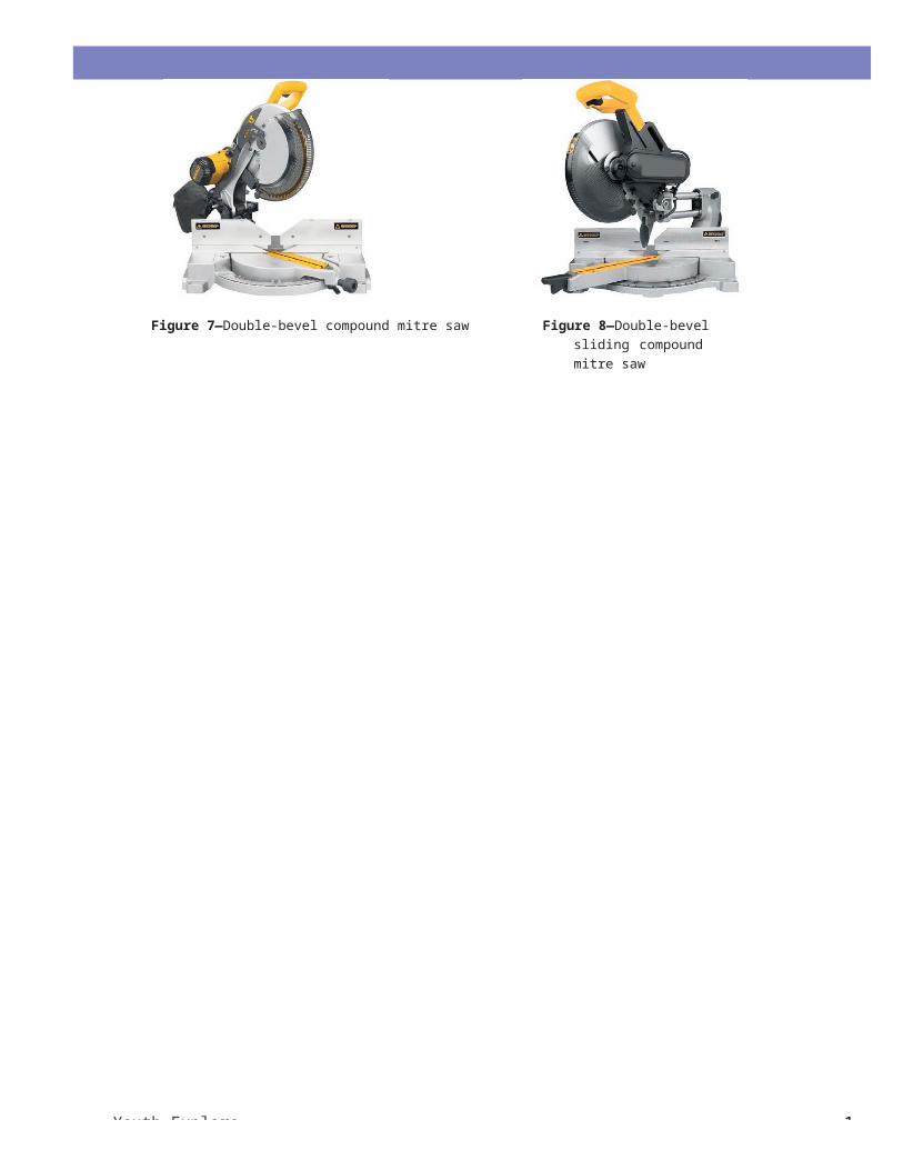
Double-Bevel Compound Mitre SawThis saw functions exactly like a compound mitre saw, except that the blade and motor assembly can flop either to the left or to the right, allowing for the cutting of bevels and compound mitres in either direction.
Double-bevel sliding compound mitre saws function the same as double-bevel compound mitre saws, but they also can slide back and forward on a rail.
Figure 7—Double-bevel compound mitre saw Figure 8—Double-bevel sliding compound mitre saw

Carpent Introduction to Carpentry Power
1Youth Explore Trades
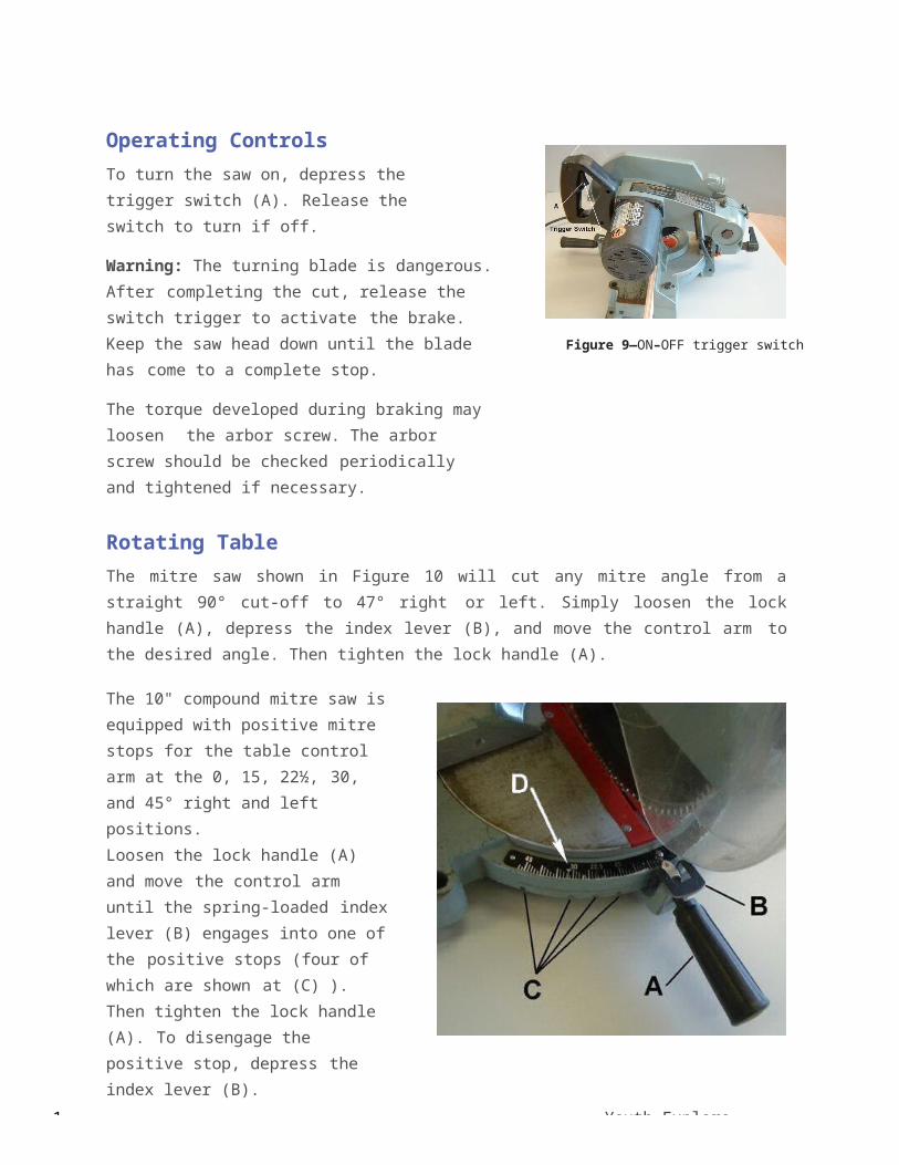
Operating ControlsTo turn the saw on, depress the trigger switch (A). Release the switch to turn if off.
Warning: The turning blade is dangerous. After completing the cut, release the switch trigger to activate the brake. Keep the saw head down until the blade has come to a complete stop.
The torque developed during braking may loosen the arbor screw. The arbor screw should be checked periodically and tightened if necessary.
Figure 9—ON–OFF trigger switch
Rotating TableThe mitre saw shown in Figure 10 will cut any mitre angle from a straight 90° cut-off to 47° right or left. Simply loosen the lock handle (A), depress the index lever (B), and move the control arm to the desired angle. Then tighten the lock handle (A).
The 10" compound mitre saw is equipped with positive mitre stops for the table control arm at the 0, 15, 22½, 30, and 45° right and left positions.Loosen the lock handle (A) and move the control arm until the spring-loaded index lever (B) engages into one of the positive stops (four of which are shown at (C) ). Then tighten the lock handle (A). To disengage the positive stop, depress the index lever (B).
Important: Always tighten the lock handle (A) before cutting.
In addition, two triangle indicators (D) are provided on the scale at the 31�⁄�° right and left mitre angle, for cutting crown moulding.
Figure 10—Rotating table

Introduction to Carpentry Power Carpent
1 Youth Explore Trades
Tilting ArmThe cutting arm of the compound mitre saw can be tilted to cut at any bevel angle from a 90° straight cut-off to a 45° left bevel angle by loosening the bevel lock handle (A) (Figure 11), tilting the cutting arm to the desired angle, and tightening the lock handle (A).
Note: The lock handle (A) is spring-loaded and can be positioned by pulling out on the handle and repositioning it on the nut located underneath the hub of the handle.
Positive stops are provided to rapidly position the saw blade at 90° and 45° to the table. The bevel angle of the cutting arm is determined by the position of the pointer (B) on the scale (C).
In addition, a triangle indicator (D) is provided on the scale at the 33 ⁄� �° bevel angle for cutting crown moulding.
Figure 11—Bevel cutting

Carpent Introduction to Carpentry Power
1Youth Explore Trades
Locking ArmWhen transporting the saw, the cutting arm should always be locked in the down position. This can be accomplished by lowering the cutting arm (A) (Figure 12) and moving the locking lever (B) to the locked position. Never carry the mitre saw by the switch handle, cutting arm or table control; this may cause misalignment. Always lift the saw by its base.
Figure 12—Locking cutting arm
Fastening HolesFastening holes are provided in the base of the saw casting for mounting. Always secure the saw with screws to prevent movement. A walking saw is always dangerous.
Figure 13—Fastening holes

Introduction to Carpentry Power Carpent
1 Youth Explore Trades
Mitre Saw AdjustmentDISCONNECT THE SAW FROM THE POWER SOURCE BEFORE MAKING ANY ADJUSTMENTS.
Two-Position FenceThe fence (A) on your mitre saw can be used in the forward position, as shown in Figure 14, or in the rear position, as shown in Figure 15. The forward position is used for cutting workpieces up to a standard 4×4" and is the most common fence position.
The rear fence position is used when cutting off or bevelling standard 2×6" workpieces.
To change the fence position, loosen the two fence locking screws, one of which is shown at (B). Position the fence (A) in either the forward or rear position and tighten the two fence locking screws (B).
Figure 14—Fence in forward position Figure 15—Fence in rear position
To quickly check to see if the saw is cutting square, cut a 2×6", flip the cut piece over, and buttit against the edge from which you cut. If the workpiece does not butt squarely, an adjustment is required (Figures 16 and 17).
Figure 16—Checking bevel error Figure 17—Bevel error

Carpent Introduction to Carpentry Power
1Youth Explore Trades
Adjusting a 90° Bevel StopLoosen the bevel lock handle, tilt the cutting arm all the way to the right, and tighten the bevel lock handle. Place one end of a square (A) (Figure 18) on the table and the other against the blade. Check to see if the blade is at 90° to the table. If an adjustment is necessary, loosen locknut (B) (Figure 19) and turn screw (C) until the other end of screw (C) contacts the casting(D) when the blade is 90° to the table. Then tighten locknut (B).
Figure 18—Bevel adjustment 1 Figure 19—Bevel adjustment 2
Adjusting a 45° Bevel StopLoosen the bevel lock handle, tilt the cutting arm all the way to the left bevel position, and tighten the bevel lock handle.
Use a combination square (A) to check if the blade is at 45° to the table (Figures 20 and 21). If an adjustment is necessary, loosen locknut (E) and turn screw (F) until other end of screw (F) contacts casting (G) when the blade is at 45° to the table. Tighten locknut (E).
These positive stops enable you to rapidly position the blade at 90° and 45° to the table.
Figure 20—Bevel adjustment 3 Figure 21—Bevel adjustment 4

2 Youth Explore Trades
Introduction to Carpentry Power Carpent
Adjusting Blade Parallel to Tabletop Insert OpeningBefore adjusting the blade parallel to the blade insert opening in the mitre saw tabletop,DISCONNECT THE SAW FROM THE POWER SOURCE.
Note: This adjustment should be checked with the cutting arm moved all the way to the right (blade 90° to the table).
Lower the cutting arm. The saw blade (A) should be parallel to the left edge (B) of the table insert opening (Figure 22). If anadjustment is necessary, loosen two screws(C) and move the cutting arm until the blade is parallel with the left edge (B) of the table insert opening. Then tighten two screws (C).
Figure 22—Blade parallel to bladeinsert opening in tabletop
Adjusting Fence 90° to BladeBefore adjusting fence 90° to blade, DISCONNECT THE SAW FROM THE POWER SOURCE.
Note: This adjustment must be made twice, once with the fence in the forward position and again with the fence in the rear position.
Loosen the two fence locking screws, one of which is shown at (A), and move the fence (B) all the way to the forward position (Figures 23 and 24). Then tighten the two fence locking screws (A).
Lower the saw blade and lock the cutting arm in the down position. Place one edge of a square(C) against the blade and the other end against the fence, as shown. Check to see if the fence is 90° to the blade.
If an adjustment is necessary, loosen the two fence locking screws (A) and turn the two adjusting screws, one of which is shown at (D), until you are sure the fence is at 90° to the blade when the fence is all the way forward. Then tighten the two fence locking screws (A).
Figure 23—Fence adjustment 1 Figure 24—Fence adjustment 2

Carpent Introduction to Carpentry Power
2Youth Explore Trades
For the second adjustment, loosen the two fence locking screws, one of which is shown at (A), and move the fence (B) all the way to the rear position, as shown (Figures 25 and 26). Then tighten the two fence locking screws (A).
Using a square, place one end of the square against the blade and the other end against the table and check to see if the fence is 90° to the blade. If an adjustment is necessary, loosen the two fence locking screws (A) and turn the two adjusting screws, one of which is shown at (E), until you are sure the fence is at 90° to the blade when the fence is all the way to the rear. Then tighten the two fence locking screws (A).
These adjustments enable you to rapidly position the fence in either the forward or rear position making sure that the fence will be 90° to the blade.
Figure 25—Fence adjustment 3 Figure 26—Fence adjustment 4
Adusting the Sliding Fit of the Cutting Arm for Vertical Travel
Before adjusting the sliding fit of the cutting arm for vertical travel, DISCONNECT THE SAW FROM THE POWER SOURCE.
To adjust the sliding fit between the arm(A) and bracket (B), tighten or loosen the adjusting nut (C) (Figure 27). Correctadjustment is achieved when a good snug sliding fit is obtained without any side movement between the arm (A) and bracket (B). This adjustment should not be so tight that it restricts the sliding movement or so loose that it affects the accuracy of the saw cut.
Figure 27—Cutting arm

Introduction to Carpentry Power Carpent
2 Youth Explore Trades
Adjusting Saw Blade Downward TravelBefore adjusting the downward travel of the saw blade, DISCONNECT THE SAW FROM THE POWER SOURCE.
The downward travel of the saw blade can be limited to prevent the saw blade from contacting any metal surfaces of the machine. This adjustment is made by loosening locknut (A) and turning adjusting screw (B) in or out (Figure 28). When making this adjustment, make sure the machine is disconnected from the power source and lower the blade as far as possible. Rotate the blade by hand to make certain the teeth do not contact any metal surfaces.
Figure 28—Downward travel
MaintenanceMaintainence of a mitre saw is similar to that of most portable power tools. The blade should be replaced when it becomes dull, and all electrical cords and connections must be kept in good condition.
Mitre saws are moved to and from the job site daily. This continual moving loosens screws and bolts. Regularly tighten all bolts and screws. Replace any parts that may have come loose or been lost.
Before using any mitre saw, check that the guard is moving freely and protects the blade fully. Never use a saw with the guard held back or if it is not operating correctly.
Clean the saw weekly. Remove all sawdust and pitch. Lubricate all moving parts with light oil and then wipe clean.
Carpent Introduction to Carpentry Power
2Youth Explore Trades
Brush Inspection and ReplacementCAUTION: BEFORE INSPECTING BRUSHES, DISCONNECT THE MACHINE FROM THE POWER SOURCE.
Brush life varies, depending on the load on the motor. Check the brushes after the first 50 hours of use for a new machine or after a new set of brushes has been installed.
The brush holders (A) are located opposite each other on the motor housing (Figures 29and 30). When the carbon on either brush is worn to ⁄� ��" in length or if either spring or shunt wire is burned or damaged in any way, replace both brushes. If the brushes are found serviceable after removing, reinstall them in the same position as before they were removed.
Figure 29—Brush location Figure 30—Brush inspection
Changing the BladeUse only crosscutting saw blades. When using carbide-tipped blades, make sure they have a negative hook angle.
Do not use blades with deep gullets as they can deflect and contact the guard.
DISCONNECT THE MITRE SAW FROM THE POWER SOURCE BEFORE INSTALLING THE BLADE.
Introduction to Carpentry Power Carpent
2 Youth Explore Trades
Blade RemovalRotate the lower blade guard (clear plastic) up and out of the way. Loosen screw (B) to free plate (C). This will expose the arbor nut.
To lock the blade from rotating you can use a scrap of wood or push on the arbor lock near the saw handle (Figure 31).
Figure 31—Guard removal
Figure 32—Rotation lock Figure 33—Blade removal
Blade InstallationReinstall a new blade by confirming rotation, holding the blade from turning, and replacing the washer and nut.
Swing guard plate (C) into position and lock by tightening the screw.
Figure 34—Blade installation Figure 35—Guard replacement

Youth Explore Trades Carpent
Overview and Working Conditions of the Carpentry and Joinery Trades
DescriptionThere are two fields of woodworking trades within the construction industry in British Columbia:Carpenters and cabinetmakers (also known as joiners). Both share some common training and both involve working primarily with wood. Both of these trades offer apprenticeships, during which on-the-job training as well as classroom experience take place. Typically, anapprenticeship is a four-year process, with 85% of the training spent on the job and 15% spent in school (technical training). The activity plans written for Youth Explore Trades concentrate on the basic skills of both woodworking trades, although much of the material is specifically suited for carpentry training.
Lesson OutcomesThe student will be able to:
• Understand the main duties of carpenters• Know the difference between a carpenter and a cabinetmaker• Be aware of the working conditions of a carpenter
Assumptions• Students will have little or no knowledge about the carpentry trade.
• Students will have an interest in gaining knowledge about the carpentry trade.
TerminologyCabinetmaker (joiner): a person who builds, repairs, and restyles wooden furniture, cabinets, fixtures, and other products. There are many similarities with the carpentry trade, andboth involve primarily working with wood. Joiners are designated as cabinetmakers under the Interprovincial Red Seal Program. Using architectural drawings, joiners often operatewoodworking machines to cut and form parts, which they then assemble into finished products. Some specialize in custom-made furniture, and increasingly joiners are tasked with installing pre- manufactured cabinets and fixtures.
Carpenter: a person who builds and repairs a vast array of structures made of wood, wood substitutes, and other materials. Carpenters assemble and erect forms for concrete, wood and metal frame construction and use plans and instruments to prepare for excavating and shoring. On smaller projects, they direct concrete placement and install exterior and interior finish materials such as siding, doors, windows, and cabinets.
This work is licensed under a Creative Commons Attribution-NonCommercial-ShareAlike 4.0 International License unless otherwise indicated. 25

Overview and Working Conditions of the Carpentry and Joinery Carpent
2 Youth Explore Trades
Essential Skills: ITA Essential Skills were created to help people prepare for success in the first two levels of technical training during their apprenticeship. Essential Skills focus on foundation skills such as reading, math, and document use. Each trade requires Essential Skills, but to different degrees. For example, both carpenters and bakers use math, but electricians need trigonometry and bakers do not.
Industry Training Authority (ITA): the organization responsible for leading and coordinating the skilled trades training and credentialing system for the province of BC. ITA provides strategic leadership, policy support, and customer services to help apprentices, employers, and industry. ITA sets program standards, maintains credential records, and issues the highly regarded Interprovincial Red Seal (IP) and BC Certificate of Qualification (CofQ) credentials.
Interprovincial Red Seal and BC Certificate of Qualification: Through the Red Seal program, certified tradespeople can obtain a “Red Seal” endorsement on a BC Certificate of Qualification. The Red Seal allows qualified tradespeople to practise their trade in any province or territory in Canada where the trade is designated, without having to write further examinations.See www.red-seal.ca for additional information on the Red Seal Program. CofQ is only recognized in the province where it is obtained.
National Occupational Classification (NOC): standardized language for describing the work performed by Canadians in the labour market. It gives statisticians, labour market analysts, career counsellors, employers, and individual job seekers a consistent way to collect data and describe and understand the nature of work.
Technical training: in-school training—in the case of this activity plan, for the carpentry trade.
Working conditions: the conditions in which an individual works, including environment, noise levels, degree of safety, physical environment, wages, and hours of work.
Estimated Time1.5–3 hours
Recommended Number of Students20, based on the BC Technology Educators’ Best Practice Guide
FacilitiesClassroom or computer lab
ToolsProjector with computer and speakers, Internet access

Carpent Overview and Working Conditions of the Carpentry and Joinery
2Youth Explore Trades
MaterialsNone
RecommendedThe introduction of this s is a great opportunity to invite a carpenter in as a guest speaker to talk about the carpentry trade. The person could speak to the students about duties performed bya carpenter and working conditions, and could provide stories about the trade as well as share their experiences as an apprentice. Alternatively, a cabinetmaker could also present an overview of the cabinetmaking (joiner) trade.
ResourcesSkills Canada 2008—Carpentry
Keewatin Career Development Corporation (KCDC) video. This video demonstrates this trade in action, performed during the Skills Canada Competition 2008 in Calgary.
http://www.youtube.com/watch?v=EnITU2kOCfE
Skills Canada 2008—Cabinetmaking
Keewatin Career Development Corporation (KCDC) video. This video demonstrates this trade in action, performed during the Skills Canada Competition 2008 in Calgary.
http://www.youtube.com/watch?v=4fBQ6M_4DCc
Industry Trades Association of BC (ITABC) Carpenter information
http://www.itabc.ca/program/carpenter
Industry Trades Association of BC (ITABC) Cabinetmaker information
http://www.itabc.ca/program/cabinet-maker-joiner
Employment and Social Development Canada—National Occupational Classification
http://noc.esdc.gc.ca/English/home.aspx

Overview and Working Conditions of the Carpentry and Joinery Carpent
2 Youth Explore Trades
Activity
Option 1: Guest Speaker Carpenter or CabinetmakerThe following activity would be optimal prior to a carpenter or cabinetmaker coming in to speak to students:
• The teacher shows video clips listed under the Resources section, including the video of a carpenter’s duties, so students know the difference between the two different types of woodworking trades.
• The teacher leads a discussion and provides an overview to the carpentry trade, explaining the NOC and main duties of carpenters.
Option 2: No Guest Speaker (Class Discussion)• Show one or both video clips as a starting point to the activity.
• Give an overview of the carpentry trade explaining the NOC and main duties of carpenters. Lead a class discussion.
• Show the video of a cabinetmaker’s duties (see Resources section) so students know the difference between the two different types of carpenters.
Note: This video is from Alberta, where some of the requirements are different from those in British Columbia, such as educational requirements.
Option 3: No Guest Speaker (Class Activity)• Show one or both video clips as a starting point to the activity.
• Give an overview of the carpentry trade, explaining the NOC and main duties of carpenters.
• Show the video of a cabinetmaker’s duties so students know the difference between the two different types of carpentry trades (see Resources section).
Note: This video is from Alberta, where some of the requirements are different from those in British Columbia, such as educational requirements.
• Hand out slips of paper with duties and descriptions of carpenters and cabinetmakers. Students must decide whether the papers fit carpenters, cabinetmakers, or both. Have them lay the papers down on a table with carpentry on the left, both in the middle, and cabinetmaking on the right (a Venn diagram format with two overlapping circles). The list of duties and descriptions is included at the end of this activity.

Carpent Overview and Working Conditions of the Carpentry and Joinery
2Youth Explore Trades
Background informationNOC #7271 CarpentersCarpenters construct, erect, install, maintain, and repair structures and components of structures made of wood, wood substitutes, lightweight steel, and other materials. They are employed by construction companies, carpentry contractors, and maintenance departments of factories, plants, and other establishments, or they may be self-employed.
Main dutiesCarpenters perform some or all of the following duties:
• Read and interpret blueprints, drawings ,and sketches to determine specifications and calculate requirements
• Prepare layouts in conformance to building codes, using measuring tools
• Measure, cut, shape, assemble, and join materials made of wood, wood substitutes, lightweight steel, and other materials
• Build foundations, install floor beams, lay subflooring, and erect walls and roof systems
• Fit and install trim items, such as doors, stairs, moulding, and hardware
• Maintain, repair, and renovate residences and wooden structures in mills, mines, hospitals, industrial plants, and other establishments
• Supervise apprentices and other construction workers
• May prepare cost estimates for clients
NOC #7272 CabinetmakersCabinetmakers use a variety of woods and laminates to construct and repair wooden cabinets, furniture, fixtures, and related products. They are employed by furniture manufacturing or repair companies, construction companies, and cabinetmaking contractors, or they may be self- employed.
Main dutiesCabinetmakers perform some or all of the following duties:
• Study plans, specifications, or drawings of articles to be made, or prepare specifications
• Mark outlines or dimensions of parts on wood
• Operate woodworking machines, such as power saws, jointers, mortisers, and shapers, and use hand tools to cut, shape, and form parts and components

3 Youth Explore Trades
Overview and Working Conditions of the Carpentry and Joinery Carpent
• Trim joints and fit parts and subassemblies together to form complete units using glue and clamps and reinforce joints using nails, screws, or other fasteners
• Sand wooden surfaces and apply veneer, stain, or polish to finished products
• Repair or restyle wooden furniture, fixtures, and related products
• May estimate the amount, type, and cost of materials required
Evaluation GuidelinesThe student:
• participates in class discussion.
• Understands the difference between carpenters and cabinetmakers.
• Displays an understanding of the main duties of a carpenter and a cabinetmaker. The teacher will assess this on the basis of student activity, participation, and discussion.

Youth Explore Trades Carpent
Woodshop Safety and Introduction to Hand Tools
DescriptionA woodworking environment presents a variety of potential safety hazards and requires an ongoing awareness of the dangers involved in using both hand and power tools. Additionally, there are a number of hand tools specific to carpentry, and students need to be introduced to both their application and the specific safety steps that should be followed to maintain a safe working environment.
The purpose of this Activity Plan is to provide students with an introduction to the general safety requirements necessary within a woodworking environment. This will be followed by a presentation of basic hand tools used in carpentry and how to use those tools in a safe manner.
Lesson OutcomesThe student will be able to:
• Identify appropriate clothing requirements in a woodworking environment• List safety equipment requirements for eye, hearing, and dust protection• Explain the dangers of drug and alcohol usage in relation to job safety• Be aware of job requirements for safety equipment, including eyewash stations, fire
extinguishers, and first aid supplies• List the common hand tools used in carpentry• Demonstrate the specific usage of those common hand tools
TerminologyCarpenter’s level (spirit level): a rectangular tool used to check the level of a surface. It consists of two flat parallel surfaces with a small window containing a cylinder filled with liquid and a bubble of air.
Figure 1—Four-vial hand level
Carpenter’s pencil: a large, rectangular pencil with a strong graphite lead typically sharpened with a knife or chisel.
Figure 2—Carpenter’s pencil
This work is licensed under a Creative Commons Attribution-NonCommercial-ShareAlike 4.0 International License unless otherwise indicated. 31

Woodshop Safety and Introduction to Hand Carpent
3 Youth Explore Trades
Chalk line: a tool for marking long, straight lines. It consists of a casing holding a rolled string and ground chalk that coats the string.
Figure 3—Chalk line
Chemical cartridge respirator: a respirator mask that consists of a dust pre-filter and a chemical cartridge specifically designed to capture hazardous fumes and other contaminants, and prevent them from causing respiratory damage.
Chisel: a hand tool with a plain handle and a long blade and beveled cutting edge, designed to be struck by a hammer or mallet. Used to cut or shape hard materials such as wood, stone or metal.
Claw hammer: a tool generally used to hammer nails or remove nails from material. It consists of a handle attached to a solid steel head with a pounding end and a claw end to hook and remove fasteners with.
Curved claw
Straight claw
Figure 4—Different claw hammers

45º mitre face
Square head
Spirit level
Scriber
Carpent Woodshop Safety and Introduction to Hand
3Youth Explore Trades
Combination square (square head): a ruled blade with both 45° and 90° heads, used to lay out right angles and 45° angles. Figure 5 shows how the square head of a combination square is used to hold the blade at right angles to the edge of stock or flat bar.
Figure 5—Square head combination square
Dry chemical fire extinguisher: a portable cylinder filled with foam or a dry chemical material. Some types include:
• Class A (ordinary combustible materials—paper, wood, or plastics)• Class B (flammable liquids—gasoline, grease, or oil)• Class C (electrical equipment—appliances, wiring)• Class D (combustible metals—sodium, magnesium)
Some dry chemical fire extinguishers can be used for a variety of fire sources (ABC).
Earmuffs: hearing protectors that consist of soft ear cushions with sound-attenuating materials fitted within rigid outer cups and attached to a headband
Earplugs: a type of hearing protection device in which preformed silicon (customized) or mouldable foam plugs (disposable) are inserted into the ear canal to reduce sound.
Emergency eyewash station: a safety device that contains saline (salt dissolved in sterile water) or warm water that can be used to flush particles or chemicals from the eye in an emergency.
First aid kit: a portable container that holds essential first aid supplies, including adhesive bandages, antiseptic solutions, scissors, and other supplies.

Woodshop Safety and Introduction to Hand Carpent
3 Youth Explore Trades
Measuring tape: a flexible ruler with linear measurement markings attached to a spring mechanism housed in a case. These may be in imperial or metric units or both.
Figure 6—Measuring tape
Nail puller: a pry bar consisting of a handle and a hooked claw end used to pull fasteners.
Figure 7—Nail puller
Particulate respirator dust mask: a disposable paper-filter mask designed to fit over the nose and mouth to prevent sawdust and other materials from causing respiratory damage. This type is not generally effective against hazardous fumes.
Personal protective equipment (PPE): protective equipment and clothing designed to shield the worker from injury. Types of PPE include eye, ear, and body protection to prevent injuries from workplace hazards such as projectiles, fumes, and excessive noise.
Safety glasses: plastic lens eyewear with a wraparound or side protection shape designed to stop foreign objects from damaging the eyes.
Semi-insert earplugs: a set of earplugs attached to a headband and placed over the outside of the ear canal to reduce sound.
Figure 8—Semi-insert earplugs

Carpent Woodshop Safety and Introduction to Hand
3Youth Explore Trades
Speed square: a triangular-shaped layout tool used for a variety of functions, including marking 90°, 45°, and specific angles, line-scribing, and as a saw guide for a portable circular saw.
Figure 9—Speed square
Tool pouch: a leather or fabric belt holding a variety of pockets used to carry tools and fastening devices.
Estimated Time1.5–2 hours
Recommended Number of Students20, based on the BC Technology Educators’ Best Practice Guide; ideal is 16.
FacilitiesTechnology education shop facility required.
Tools• Safety glasses• Sample hearing protectors• Sample dust masks and respirators• Fire extinguisher• Eyewash station• First aid kit• Tool pouch• Tape measures• Combination square

Woodshop Safety and Introduction to Hand Carpent
3 Youth Explore Trades
• Speed square• Carpenter’s level• Hammers and nail pullers• Chalk line• Carpenter’s pencil
Materials2 × 4" samples used to show layout and measuring techniques
ResourcesDeaf to the Danger—WorkSafeBC video on inappropriate use of earbuds
https://www.youtube.com/watch?v=EBzBX1OppkQ
Look at Me—WorkSafeBC video on importance of eye protection
https://www.youtube.com/watch?v=k7lTA6QQWGw

Carpent Woodshop Safety and Introduction to Hand
3Youth Explore Trades
Activity
1. This activity should begin with a general discussion of safety in the workplace and introduce the overriding acknowledgement that safety is a consideration in every aspect of the carpentry trade. Students may not have any background knowledge of constructionsafety or within related trades. It needs to be emphasized that regular workplace behaviour requires a much greater degree of awareness of the dangers present both from tools and machinery and from environmental hazards such as noise and dust.
2. Workplace clothing plays an important role in safety. A brief discussion of what is considered appropriate is necessary and includes the following points to consider:
• Proper footwear—no open-toed shoes, requirements for safety footwear on many job sites
• Appropriate clothing—no shorts, muscle shirts, dangling sleeves, or cords such as those found on hoodies, etc.
• Removal of jewellery and other hazards—watches, rings, etc.
3. A discussion of workplace distractions can be introduced by having students view the short WorksafeBC video “Deaf to the Danger.” Have students brainstorm on other potential distractions that could impact safety. Appropriate use of cellphones should be mentioned.
4. As many workplace injuries result from inappropriate use of drugs and alcohol, an overview of the relevance of taking responsibility for one’s own safety and other workers should be discussed.
5. Personal protective equipment (PPE) should be demonstrated to the class. The discussion should make clear to each student when they should be used and the consequences of non-use. This discussion should include the following:
• Safety glasses• Hearing protection• Dust masks and respirators
6. The short WorkSafeBC video “Look at Me” can be used to supplement this discussion. It will provide students with a reminder that it only takes one instance of non-use of PPE to result in a serious injury.
7. Job site safety equipment is a legislated requirement, and students should be made aware of fire extinguishers, eyewash stations, and first aid kits. At this point, it would not be necessary to demonstrate each component in depth, but students should understand that all accidents should be reported immediately to the teacher and that equipment should be available at any worksite.

Woodshop Safety and Introduction to Hand Carpent
3 Youth Explore Trades
8. The final part of this activity is to provide an overview of the common hand tools used in carpentry. A brief demonstration/discussion should present the basic use and handling of each of the following:
• Tape measure (metric and imperial units)• Combination square• Speed square• Carpenter’s level• Claw hammer• Nail puller• Chalk line• Carpenter’s pencil• Chisel
Evaluation GuidelinesThe student can:
• Identify the three main elements of PPE• Demonstrate the basic use of the hand tools given• Identify the names of each of the hand tools given
Optional Extension Activity• If time is available, students could practise with the hand tools provided in the earlier
demonstration.
• As both imperial and metric units are used in carpentry, the advantages/disadvantages of each system could be discussed briefly.

Youth Explore Trades Carpent
Build a Floor
DescriptionFloors are an integral part of residential construction and must be built to specifications that meet building code requirements. In this Activity Plan, students will be cutting and assembling components of a wood frame floor (including floor joists, rim joists, and sheathing) according to drawings or specifications.
Lesson OutcomesThe student will be able to:
• Identify floor framing components• Extract information from the drawings with respect to size and location of components and/
or openings• Demonstrate safe use of hand and power tools• Use appropriate layout tools• Construct a basic floor with joists, rim joists, and sheathing• Recognize how to check and mark crown on joists• Gain the skills necessary to apply tongue and groove (T&G) plywood
AssumptionsThe student is:
• Familiar with safe use of a portable circular saw• Familiar with basic tools for measurement (tape measure) and layout (framing square)• Familiar with extracting information from drawings• Aware that floor systems must bear on beams, walls, or other significant structural
members
This work is licensed under a Creative Commons Attribution-NonCommercial-ShareAlike 4.0 International License unless otherwise indicated. 39

Build a Carpent
4 Youth Explore Trades
TerminologyBow: warping along the length of the face of a piece of lumber. Bow is typically not a concern for floor joists but the term can be discussed to provide students with an understanding of another issue often seen in lumber.
Figure 1—Bow in lumber
Box joists: joists specifically cut to form an opening in a floor (typically around a stair opening or other components).
Ledger
Box joist
Headers
Cut joists
Box joist
Offset between joist cut line
and ceiling cutout
Figure 2—Common header and box joists

Carpent Build a
4Youth Explore Trades
Crown: warping by arching (on edge) of a piece of lumber due to drying conditions. The crown on a floor joist should always be placed arching up toward the top of the structure.
Figure 3—Crown in lumber
Double joist: two joists screwed or bolted together to create a stronger joist.
Floor fasteners: nails or screws used to fasten the subfloor plywood to the floor joists. Typical fasteners include ring nails (small directional rings on the shank to prevent the nail from working back out once driven in); galvanized nails (zinc treated to provide a rough finish resulting in very high corrosion resistance and to prevent the nail from working back out); and subfloor screws (treated with zinc to prevent corrosion and breakage).
Floor joist: one in a series of parallel framing members that support a floor load. Joists are supported by beams or bearing walls.
Figure 4—Isometric view of a typical floor showing floor joists and rim joists

Build a Carpent
4 Youth Explore Trades
Floor opening: a hole or opening in a floor, roof, or platform that measures 12" or more in its least dimension, wide enough to permit a person to fall through.
Floor sheathing (sheeting): plywood, oriented strand board (OSB), or lumber used to close up floors before the installation of finish materials on the surface. This is also known as subflooring. Tongue and groove plywood (T&G) is recommended. T&G plywood is specifically designed so that each piece has a slot (the groove) cut all along one edge, and a thin, deep ridge (the tongue) on the opposite edge (Figure 5). The tongue projects a little less than the depth of the groove.Two or more pieces thus fit together closely with less movement or flexing.
Figure 5—Tongue and groove plywood
Header joist: a joist positioned horizontally between two longer joists in order to frame around an opening.
Joist hanger: a metal bracket used to attach and support the ends of a wood joist to beams or other structural components.
Rim joist: the final joist that attaches to the end of the row of joists that support a floor or ceiling. A rim joist forms the outside edge of the box that makes up the floor.
Estimated Time2–6 hours
The time for this activity will depend on the familiarity of students with tools and the scope of the project (e.g., size and shape of floor, whether it includes openings, availability of tools, spacious work environment).
Recommended Number of Students20, based on the BC Technology Educators’ Best Practice Guide. The ideal is 16, working in teams of 2–4 students, depending on the size and scope of the floor(s) being constructed.
FacilitiesTechnology education shop facility is ideal, as well as a large secure outdoor space to work.

Carpent Build a
4Youth Explore Trades
Tools• Portable circular saws• Extension cords• Tape measures• Combination or speed squares• Hammers or pneumatic nailers• Sledge hammers (required to apply T&G flooring)• Framing squares• Levels• Nail bars• Aprons• Hard hats, eye protection, and hearing protection
Materials• 2 ×?" material for joists (2 × 4" maybe adequate, but 2 × 6", 8", 10", or 12" may be
more appropriate depending on the size of the project and joist span)• Floor sheathing (plywood or OSB)• 3" common bright nails, for nailing floor joists• 2" common ring nails or 2" galvanized nails for nailing floor sheathing. If the sheathing
material is to be reused at a later date, it is recommended to use 2" subfloor screws for ease of removal.
ResourcesGraphic/photo of floor system with cross section as well as isometric drawing.
Sample drawings of the floor should be provided (possibly as a standalone, and as a portion of a shed-style project if the floor is part of a larger project).
12’–0"1'– 4" Rim joist
Build a Carpent
4 Youth Explore Trades
Activity
1. Review terminology and safe practices.
2. Determine the size and shape of the floor, and determine the position of any floor openings (for this project it is recommended that a simple floor without openings be built).
13¾"
14 ½"
13¾"
Attach (10) 8' × 2" × 6" joists to (2) 12' × 2" × 6" rim joists resting on the (3) 4" × 6" beams. Install blocking
between joists.7 at 14 ½" and the two outside at 13 ¾"
Figure 6—Sample drawing illustrating basic measurements and spacing between joists for a floor
3. Generate a material list, including the number of joists and sheathing requirements.
4. Establish a positioning strategy for the floor to be built (cinder blocks under corners, etc.). This would depend on the shop floor, mezzanine, or other building area available.
5. Select lumber to be used for joists and physically examine each piece to determine any crown present. The crown edge should be marked with a large V to identify it, and all crowns should face up when fastening.
6. Cut the rim joists to length using a portable circular saw or mitre saw.
7. Transfer the joist layout to the rim joists. Ensure correct spacing of 16" from the outside of edge of the first joist to the centre of the second joist and 16" spacing OC for eachcontinuing joist. The spacing should be marked out using a speed square or framing square with a line and an X to indicate the side to which the joist will be fastened.
8. Cuts the joists to length with a portable circular saw or mitre saw and nail with 3" common nails between the rim joists, making provisions for any floor openings.
8'–
0"

Strength/ major axis
Joists or trussesStagger panel end joints
Blocking if square edge panel
T&G panels applied across supports with mark “THIS SIDE DOWN” placed down. All panels are to be continuous over two or more spans.
Carpent Build a
4Youth Explore Trades
9. Ensure the floor joists are square by measuring the floor diagonally and adjusting as necessary.
10. Apply floor sheathing. (It is recommended that sheathing be applied using screws in order to remove and reuse the material later.) Sheathing sheet ends must overlap to the centre of the joists and be staggered if more than one row is applied (Figure 7).
The T&G sheathing is applied by laying down the plywood with the tongue edge inserted into the groove of the previously applied sheet. A long 2 × 4" is laid flat on the joists against the groove side and tapped with a sledge hammer to drive the tongue tightly into the groove of the adjacent sheet. (The 2 × 4" allows for even pressure and prevents damage to theedge of the plywood.)
" minimum gap at panel ends and edges or follow manufacturer recommendations.
T&G edges should be butted lightly together.
Figure 7—Typical sheathing placement with staggered end joints
11. It must be determined in advance if the floor is going to simply rest upon an existing level floor, or if it is going to bear upon pier blocks, beams, or established foundation walls so that students can make the appropriate accommodations.

Build a Carpent
4 Youth Explore Trades
Evaluation GuidelinesThe student:
• Uses appropriate safety equipment and procedures• Selects appropriate tool(s) for the task• Sequences operations correctly• Produces accurately cut and correctly laid out framing components• Correctly assembles and fastens together framing members• Produces systems that are square, plumb, and/or level as required• Cuts and applies sheathing correctly with the appropriate fastening system• Exhibits overall professional quality (flush joints, no bent nails, appropriate material quality
selection—e.g., crowns and bows)• Maintains a tidy work environment. This includes removing scrap materials and storing
tools and materials appropriately.
Optional Extension ActivityIt may be beneficial to include discussion of the following:
• Joist hanger: a metal device shaped like a “U,” used to connect a joist and beam at right angles to each other.
• Bridging (block or cross): a method of lateral bracing between joists for stiffness, stability, and load distribution.
• Tail joist (tail beam): a short beam or joist with one end set in a wall and the other supported by a header.

Youth Explore Trades Carpent
Lay Out a Full Height Wall
DescriptionBuilding codes require that framed walls conform to specifications, and carpenters need to meet those requirements. An understanding of the basic structure and components of a wall system is essential for anyone involved in the building trades. In this Activity Plan, students will:
• Be introduced to the common terminology used in residential wall construction• Transfer the details of a drawing into the actual layout of a full-sized wall by calculating
the necessary materials and completing a material list sheet
This activity is the first stage of the actual construction of a garden shed, playhouse, or other framed structure. The actual structure will depend upon the class composition, time available for the project, and space availability.
Lesson OutcomesThe student will be able to:
• Identify the components of a wall• Identify the purpose of each wall component• Extract information from drawings• Generate a simple material list necessary to build a wall
TerminologyBase plate (also called floor plate, sole plate, or bottom plate): a horizontal structural member to which the wall studs are through nailed and which forms the base of the wall when assembled.
Cripple stud: a short stud located between the top of the header and the bottom of the top plate over a door or window. It also refers to the short studs located between the window frame and the floor plate below.
Exterior sheathing: sheets of material fastened to the exterior of a framed wall; typically made of plywood or oriented strand board (OSB).
Exterior wall: a framed wall used on the outside of a structure that contains insulation and is typically framed with 2 × 6" material.
Flush: a term used in construction to indicate that two meeting surfaces are aligned on the same plane.
Interior wall: a framed wall used on the inside of a structure that does not contain insulation and is typically framed with 2 × 4" material.
This work is licensed under a Creative Commons Attribution-NonCommercial-ShareAlike 4.0 International License unless otherwise indicated. 47

Lay Out a Full Height Carpent
4 Youth Explore Trades
Jack stud: the stud located on each side of a door or window opening that runs from the top of the bottom plate to the underside of the header.
King stud: the full-length stud located on each side of a window or door opening.
Level: a term used in construction to refer to a horizontal surface.
On centre (OC): this term implies that the measurement from the centre of one stud or joist to the centre of the next identical component will be exactly the distance specified.
Plumb: a term used in construction to refer to a vertical surface.
Square: a term used in construction to refer to a 90° angle.
Top plate: a horizontal structural member to which the wall studs are through nailed and which forms the top of the wall when assembled.
Wall stud: a vertical member in light frame wall construction usually spaced at 16" or 24" centre to centre.
Standard corner postO.C.stud
King stud
Double top plateTop plate
Headers
Cripple stud
Let-in ribbon
Window rough openingJack or trimmer stud
Door rough openingJack studKing stud
Cut-in Cut-in
Rough
Cripple
Partition
Bottom or
Energy-bracing bracing sill stud assembly sole plate efficientkicker Cut-in
bracing kicker
corner
Figure 1—Typical wall framing components
Extension TerminologyBuilding code: a set of rules that list the structural requirements for buildings and other structures. The purpose of building codes is to ensure that builders meet necessary

Carpent Lay Out a Full Height
4Youth Explore Trades
building bylaws and health requirements.
Gluelam (glued-laminated timber): a structural timber product manufactured by gluing together individual pieces of dimension lumber under controlled conditions.

Lay Out a Full Height Carpent
5 Youth Explore Trades
Insulation: any material added to a building structure for thermal, acoustic (sound), or fire protection. Typically, the term refers to fibreglass material used to thermally insulate walls.
Membrane: breather membranes (commonly known as housewrap) are engineered for the purposes of providing protection to buildings and their occupants from external climatic conditions and from the effects of condensation.
Metal studs: steel framing is often used in place of wood in commercial construction. The advantages over wood are that steel studs are always straight, don’t warp, shrink, or split, and store easily. They cost more than wood studs.
Rainscreen: the weather-facing surface of an exterior wall positioned to provide a space in front of it and the surface of the structural wall. Rainscreen protects the interior from water seepage.
Vapour barrier: any material used for damp-proofing (typically a plastic sheet) that resists movement of moisture through walls, ceiling, and floors of buildings.
Estimated Time1½–2 hours
Recommended Number of Students20, based on the British Columbia Technology Educators’ Best Practice Guide. The ideal is 16. Groups of 3–4 students for each wall section are recommended, but this would depend on the project size and scope.
FacilitiesThis specific activity can be facilitated in a classroom setting, as it involves the introduction of terminology and the calculation of materials needed for the upcoming construction project.
Tools• Calculators (optional)
Materials• Blank material list sheets• Sample materials, including the following:
1. 2 × 4"s or 2 × 6"s for plates and studs2. 2 × 6" or 2 × 8"s (optional) for lintels3. Sheathing (OSB, plywood)4. 3" common nails for studs5. 2" common nails for sheathing (If the structure is to be dismantled, wood screws are
recommended for ease of takedown.)

5 Youth Explore Trades
Lay Out a Full Height Carpent
OptionalAlternative materials used in frame construction (metal studs, gluelam beams)
ResourcesA graphic/photo of a finished exterior wall, i.e., a crosssection of a framed wall.
Copies of the drawings of the actual project being built. This could be a garden shed, playhouse, or other framed structure.
16"oc oc 16"
oc 16" oc
Figure 2—Typical stud frame spacing of a wall
Stud
Top plat
e
Studs
Sole plat
Stud

Carpent Lay Out a Full Height
5Youth Explore Trades
Activity
1. Review terminology and safe practices.
2. Provide students with an overview of wall components. This discussion should include an overview of the following:
• The purpose of a wall• The typical components that form a wall• The specific requirements of materials, sizing, correct spacing, and fastening devices
used to build an exterior wall• The specific requirements of materials, sizing, correct spacing, and fastening devices
used to build an interior wall
3. Determine the size of the wall project required and provide each group of students with drawings showing the size and correct location of various components, including plates and studs.
4. Determine the length of the wall plates, stud spacing, and size and positioning of openings in the wall. (It is recommended that this first wall not contain openings if a second wall is to be built.) Typically this wall should have stud spacing with 16" centres (Figure 2).
5. Students should generate a material list for the wall to be constructed. This list should include the number and size of plates, number and length of studs, and size of nail fasteners required.
6. If time permits, students can also calculate the amount of insulation that would be required to insulate the wall. They could also calculate the number of sheets of wall sheathing that would be required.
Evaluation GuidelinesThe student is able to:
• Identify the main components of a wall• Describe the purpose of those components• Generate an accurate material list for a simple stud wall structure• Calculate the required amount of insulation and the required amount of exterior sheathing
(optional)

Lay Out a Full Height Carpent
5 Youth Explore Trades
Extension ActivitiesIt is recommended that the instructor spend some time discussing:
• The importance of building codes and how they are used within the construction industry• Some of the important factors that are found specifically in the BC building code, such
as rainscreen technology, membrane, and vapour barrier, and how these materials and technologies specifically relate to our climate
• Alternate materials now being used in construction (metal studs and glued laminated lumber)

Youth Explore Trades Carpent
Build a Full Height Wall
DescriptionStandard wall sections are an important feature in residential house construction, and their components must conform to building code specifications. In this lesson, students will build a wall section that meets code requirements.
Wall sections created in this Activity Plan could also be used later for wiring and plumbing.
Lesson OutcomesThe student will be able to:
• Identify the parts of a wall• Extract information from drawings• Lay out a wall according to specifications• Place and fasten wall components in the correct location• Demonstrate safe use of hand and power tools
AssumptionsStudents are familiar with:
• Extracting information from drawings• The use of basic measurement and layout tools• The safe use of the compound mitre saw and portable circular saw
Students will have completed:
• Build a Wall Mockup (mini-wall) activity plan• Lay Out a Full Height Wall activity plan
TerminologyBase plate (also called floor plate, sole plate, or bottom plate): a horizontal structural member to which the wall studs are through nailed and which forms the base of the wall when assembled.
Exterior wall: a framed wall used on the outside of a structure that contains insulation and is typically framed with 2 × 6" material.
Flush: a term used in construction to indicate that two meeting surfaces are aligned on the same plane.
Interior wall: a framed wall used on the inside of a structure that does not contain insulation and is typically framed with 2 × 4" material.
This work is licensed under a Creative Commons Attribution-NonCommercial-ShareAlike 4.0 International License unless otherwise indicated. 53

Build a Full Height Carpent
5 Youth Explore Trades
Level: a term used in construction to refer to a horizontal surface.
On centre (OC): This term implies that the measurement from the centre of one stud or joist to the centre of the next identical component will be exactly the distance specified.
Plumb: a term used in construction to refer to a vertical surface.
Square: a term used in construction to refer to a 90° angle.
Top plate: a horizontal structural member to which the wall studs are through nailed and which forms the top of the wall when assembled.
Wall stud: a vertical member in light frame wall construction usually spaced at 16" or 24" centre to centre.
Estimated Time2–4 hours
The time for this activity will depend on the familiarity of students with tools and the scope of the project (e.g., size of wall, access to tools—number of saws available, etc.—and numbers of students).
Recommended Number of Students20, based on the British Columbia Technology Educators’ Best Practice Guide. The ideal is 16. Groups of 3–4 students for each wall section are recommended, but this would depend on the project being built.
FacilitiesTechnology education shop facility required. Secure space to work outside is advantageous.
Tools• Tape measures• Hammers• Combination or speed squares• Level• Nail bar (nail puller)• Aprons• Hard hats, eye protection, and hearing protection• Mitre saw• Portable circular saw• Extension cord (if necessary)

Carpent Build a Full Height
5Youth Explore Trades
Materials• 2 × 4"s or 2 × 6"s for wall plates and studs• Sheathing (optional): OSB, plywood• 3" common nails – for nailing studs• 2" common nails – for nailing sheathing if required (if reusing materials, it is recommended
to use screws for ease of removal)
ResourcesGraphic/photo of finished exterior wall, crosssection of finished exterior wall
Drawings of wall should be provided (e.g., Figure 1). Wall to be built will depend on project and space available.
16"oc oc
16"oc 16" oc
Figure 1—Typical wall section showing plates and stud placement
Stud
Top plat
e
Studs
Sole plat
Stud

Build a Full Height Carpent
5 Youth Explore Trades
Activity
1. Review terminology and safe practices.
2. Determine the length of the wall plates and stud spacing to match the project material list. (Use the material list generated in Activity Plan: Lay Out a Full Height Wall.)
3. Cut the top and bottom plates to length and tack together in order to facilitate the layout of stud locations.
4. Lay out the top and base plates by marking the correct location of studs using a tape measure and combination square (or speed square). Mark the location of each stud by marking an X on the correct side of a measured pencil line. Note that the second stud must be located 16" from the outside of the first stud to the centre of the second stud. All remaining studs will be located 16" OC.
When laying out walls a tape measure is hooked on the end of plates (or on floors, or the rim joists). Layout of both 16" OC or 24" OC is started by running the tape measure along the plate. Marks are then made �⁄�" short of the 16" marks on the tape (15�⁄�", 31�⁄�", 47�⁄�", etc.). An X is then placed to the right of each mark indicating on which side the stud or joist is placed. The end result will be studs on the joist being 16" OC. This same process is used for 24" OC (i.e., 23�⁄�", 47�⁄�", 71�⁄�").
Copyright © 2006 The Family Handyman magazine. All Rights Reserved.
Figure 2—Typical layout of stud location on top and bottom plates

Carpent Build a Full Height
5Youth Explore Trades
Double 2 × 6" top plate (at exterior wall)
2 × 6" corner studs (three-stud corner)
2 × 6" bottom plate
Figure 3—A typical three-stud corner for a wall;this corner arrangement allows for placement of insulation to the corner and also allows for proper installation of
drywall material to the corner. This construction feature may be utilized dependingon the project that students are working on.
5. Cut all studs to length using a mitre saw or portable circular saw.
6. Fasten the studs to the wall plates by nailing 3" common nails through the top and bottom plates.
Copyright © 2006 The Family Handyman magazine. All Rights Reserved.
Figure 4—Typical positioning and nailing of plates and studs

A B
Build a Full Height Carpent
5 Youth Explore Trades
7. Square the wall by measuring diagonally and apply sheathing. The wall is only checked for square if sheathing is to be applied before being lifted into place.
Figure 5—Method of checking for square with diagonal measurements; A and B must be equal to be square.
8. Stand the wall upright, check the wall for plumb and square, and brace it with extra material.
Figure 6—Typical temporary bracing of a wall section after checking for square and for plumb

Carpent Build a Full Height
5Youth Explore Trades
Evaluation Guidelines• Layout is correct (e.g., stud spacing, opening positioning).• Components are cut to correct length.• All framing components are flush.• The wall section is braced plumb and straight (if positioned on floor).• Safe work practices are followed.• A tidy workplace is maintained. Scrap materials are removed and tools and materials are
stored properly.

6 Youth Explore Trades
Build a Full Height WallCarpenter

Youth Explore Trades Carpent
Build a Wall Mockup
DescriptionAll walls in a house must be built to correct specifications and size in order to meet building code requirements. In this Activity Plan, students will build mock wall sections, with 48" (1200 mm) top and bottom plates and four 24" (600 mm) studs.
The purpose of this activity is to have students practise measuring, cutting, and nailing by building a small mock wall section. This lesson will be followed by the layout and construction of a full-sized wall using the skills gained.
Lesson OutcomesThe student will be able to:
• Identify the parts of a wall• Lay out a mini mock wall according to specifications• Install wall components in appropriate locations• Demonstrate safe use of hand and power tools• Demonstrate correct nailing techniques for a wall section
AssumptionsThe student will:
• Be familiar with the safe use of mitre saws and portable circular saws• Have had the opportunity to use basic measurement and layout tools• Be familiar with extracting information from drawings
TerminologyBase plate (also called floor plate or bottom plate): a horizontal structural member to which the wall studs are through nailed and which forms the base of the wall when assembled.
Double top plate: a second set of plates added after the walls are raised to position. These plates continue past the point of intersection between side and end walls and are nailed down through the top in order to lock the walls into a solid unit.
End nail technique: to install a stud or joist by nailing through the plates or rim joist into the end of the stud or joist (typically two nails at each end of a stud are used).
Exterior wall: a framed wall used on the outside of a structure that contains insulation, typically framed with 2 × 6" material.
Flush: a term used in construction to indicate that two meeting surfaces are aligned on the same plane.
This work is licensed under a Creative Commons Attribution-NonCommercial-ShareAlike 4.0 International License unless otherwise indicated. 61

Build a Wall Carpent
6 Youth Explore Trades
Interior walls: a framed wall used on the inside of a structure that does not contain insulation and is typically framed with 2 × 4” material.
Level: a term used in construction to refer to a horizontal surface.
On Centre (OC): This term implies that the measurement from the centre of one stud or joist to the centre of the next identical component will be exactly the distance specified.
Plumb: a term used in construction to refer to a vertical surface.
Square: a term used in construction to refer to a 90° angle.
Toenail technique: to install a stud in a wall by nailing through the side edge of the stud at about a 60° angle down into the plate. The nails need to be driven into the plate so that approximately half of the length of the nail is in the plate.
Top plate: a horizontal structural member to which the wall studs are through nailed and which forms the top of the wall when assembled.
Wall stud: a vertical member in light frame wall construction, usually spaced at 16" or 24" centre to centre.
Estimated Time1.5–2 hours
Time for this activity depends on the familiarity of students with tools and access to tools—the number of mitre and portable circular saws available, etc.
Recommended Number of Students20, based on the British Columbia Technology Educators’ Best Practice Guide. The ideal is16. Students will work in groups of two or individually, depending on class numbers and space available.
FacilitiesTechnology education shop facility required. A secure space to work outside is advantageous as well as open floor area in which to build the mock walls.
Tools• Mitre saw• Portable circular saw• Extension cord• Tape measures• Hammers and nail pullers• Nail gun and compressor (optional)• Combination or speed square

Carpent Build a Wall
6Youth Explore Trades
• Level• Aprons• Hard hats• Eye protection
Materials• 2 × 4"s or 2 × 6"s for wall plates and studs• 3" common nails
ResourcesGraphic/photo of finished exterior wall, crosssection of finished exterior wall. Figures 1 and 2 show examples that could be used. Drawings of a variety of walls could be provided and typical methods of construction could be discussed.
Studs are spaced 16" on centre Cripple studs are
16" on centreTop plate
Header
Jack studs are the height of your rough openings
Kings go to the outsides of the jack studs
Treated lumber for bottom plate in basementFigure 1—The main features of a typical full height wall with a framed-in door section
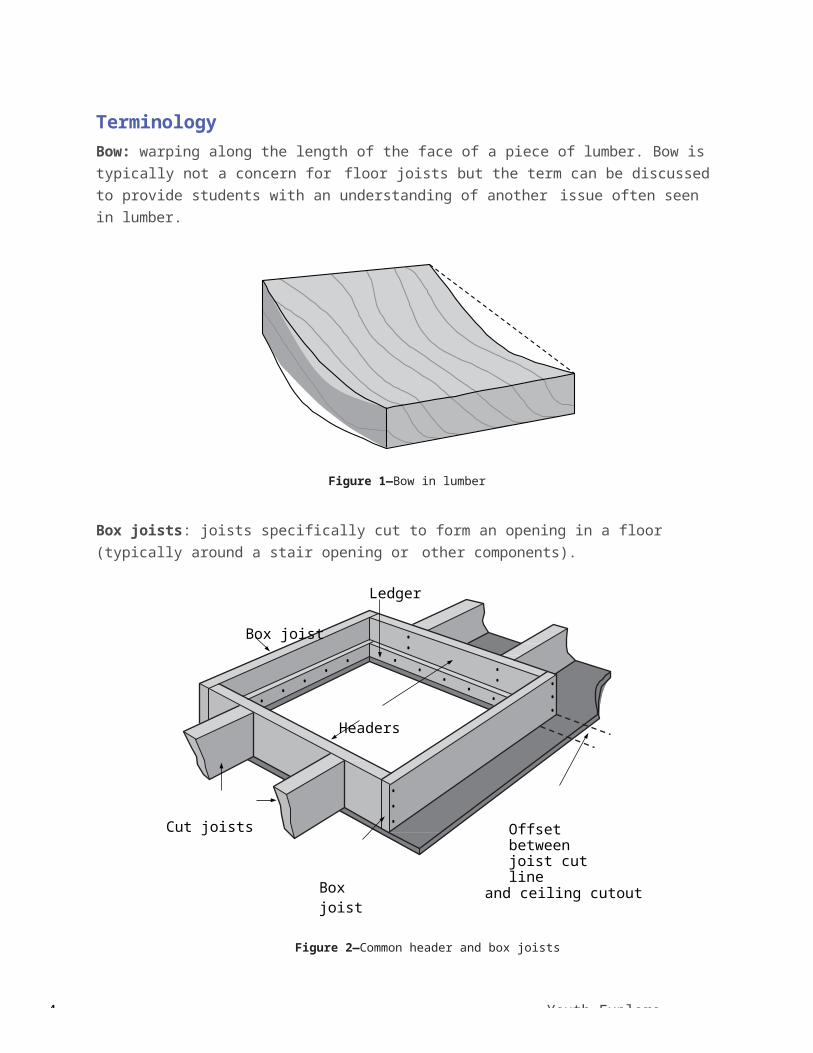
16"
16" O.C.
Build a Wall Carpent
6 Youth Explore Trades
Wall section (8 ') Top plate (`regular´ 2" × 4")
Bottom plate (treated 2" × 4") **Leave ½" of space to
allow you to tip the wall into place.
Figure 2—Typical interior wall showing correct spacing for wall studs. Note that the second stud is located 16" from the outside of the first stud
to the centre of the second stud. Each remaining stud will be 16" OC.
Floor
to jo
ist h
eigh
t (le
ss
½")*
*

Carpent Build a Wall
6Youth Explore Trades
Activity
1. Review terminology and safe practices.
2. Determine the lengths of the wall plates, stud spacing, size, and positioning. Note: 16" (406 mm) outside to centre spacing. Recommended measurements for the mock wall are 48" (1200 mm) top and base plates with four 24" (600 mm) studs.
3. Generate a material list.
4. Cut the top and base plates to length (two pieces at 48" or 1220 mm) using a compound mitre saw (Figure 3) or portable circular saw.
Figure 3—Typical compound mitre saw used to cut plates and studs to length
5. Lay out the top and base plates by marking the correct locations of studs using a tape measure and combination square (or speed square). Mark the location of the studs by marking an X on the correct side of a measured pencil line. Note that the second stud must be located 16" from the outside of the first stud to the centre of the second stud. All remaining studs will be located 16" OC.

Build a Wall Carpent
6 Youth Explore Trades
6. When laying out walls, a tape measure is hooked on the end of plates (or on floors, on the rim joists). Layout on both 16" OC or 24" OC is started by running the tape measure along the plate. Marks are then made ⅜" short of the 16" marks on the tape (15¼", 31¼", 47¼", etc.). An X is then placed to the right of each mark to indicate the side on which the stud or joist is placed. The end result will be studs on joist being 16" OC. This same process is used for 24" OC (i.e., 23¼", 47¼", 71¼").
7. Cut the wall stud components to length (four pieces at 12" or 300 mm) using a compound mitre saw or portable circular saw.
8. Assemble the wall framing components with a hammer and nails (two 3" common nails through the top plate, and two 3" common nails through the base plate). Note that students will have more success working together on this part of the activity, as they can assist in holding components in the correct position.
Figure 4—Typical nailing procedure for a wall
9. Note: The nailing process should be completed while the material is on a flat horizontal surface, in order to facilitate easy nailing (Figure 4).
10. Students need to check the mock wall to ensure that the structure is square and that studs are flush with plates. (Wall only needs to be squared if it is to be sheathed on the floor.)
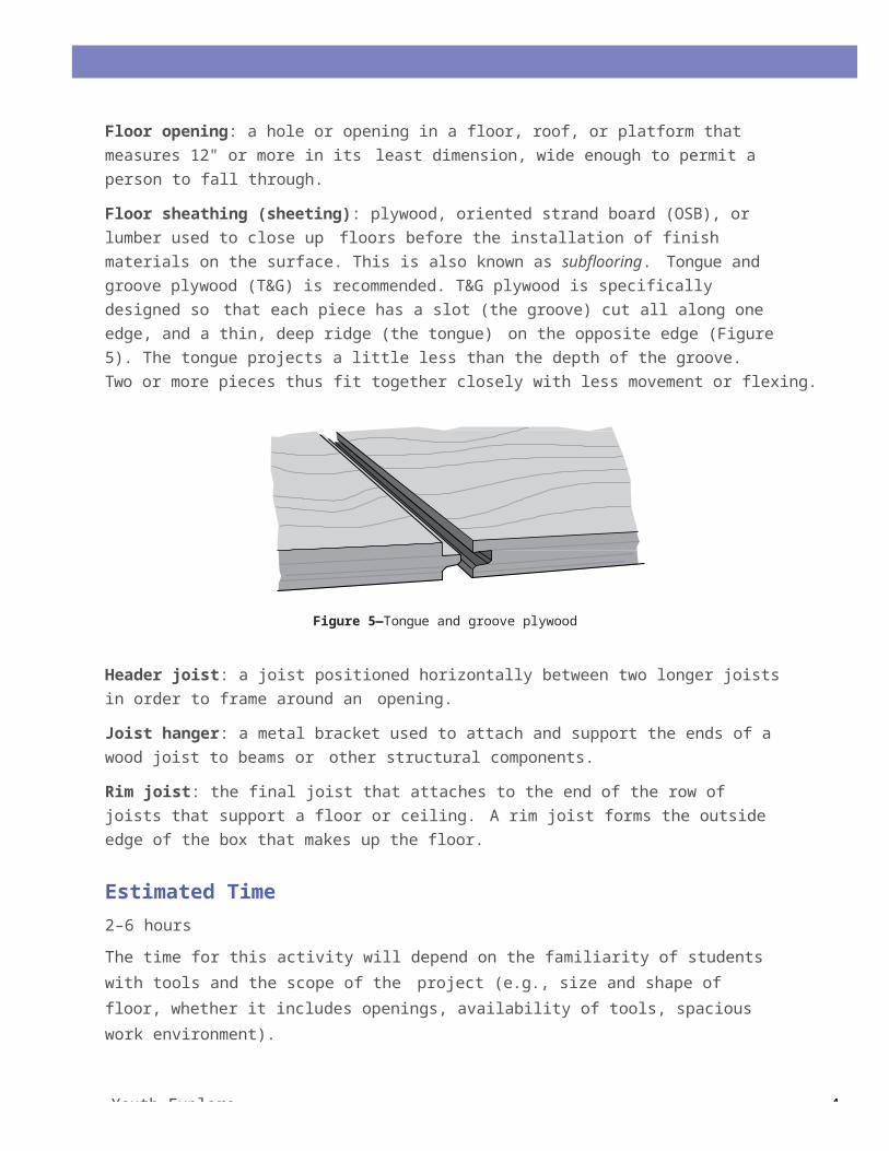
Carpent Build a Wall
6Youth Explore Trades
Evaluation Guidelines• All framing components are flush.• Layout is correct (e.g., stud spacing).• Components are cut to correct length.• Walls are square.• Safe work practices are followed.• The work environment is tidy, with tools and materials stored properly and waste
material removed.
Optional Activities• The teacher could demonstrate the assembly of part of the mock wall by using a
pneumatic nail gun, if available.• The teacher could also demonstrate toenailing techniques, and students could practise
toenailing one stud in the wall.

6 Youth Explore Trades
Build a Wall MockupCarpenter

Youth Explore Trades Carpent
Build a Sawhorse
DescriptionCarpenters need to be able to accurately interpret drawings in order to extract information. Measuring correctly, cutting accurately, and using fasteners appropriately are necessary skills that every carpenter must develop. In this Activity Plan, students will have the opportunity to develop these skills by constructing sawhorses in small groups.
Sawhorses are indispensable on a construction site and can prove to be constantly useful around the home. Their versatility is shown by their ability to function as workbenches, stepladders, vises, scaffolding, storage racks, seating, and platform and table supports.
Lesson OutcomesThe student will be able to:
• Extract information from a drawing• Proficiently perform basic measuring and layout• Cut materials in an accurate and safe manner using appropriate tools• Join materials together using appropriate fasteners• Build a sawhorse that can be used in other activities within the course
AssumptionsThe student will:
• Have an understanding of measurement systems used in carpentry and the use of tape measures, squares, and basic layout techniques.
• Have had an introduction to the safe use of basic hand tools and portable power tools, including portable circular saws, mitre saws, and hammers.
• Be aware of common fastening devices, including common and finishing nails, woodscrews, and wood glue.
TerminologyGusset (cleat): a strip of wood used to strengthen or support the surface to which it is attached.
Sawhorse: a beam with four legs used to support a board or plank for sawing. Commonly used to support lumber, or as a work surface.
Sliding T bevel: an adjustable gauge for setting and transferring angles.
This work is licensed under a Creative Commons Attribution-NonCommercial-ShareAlike 4.0 International License unless otherwise indicated. 69

Build a Carpent
7 Youth Explore Trades
Estimated Time3 hours
The time for the activity will depend on the familiarity of students with tools and their access to tools—e.g., the number of mitre saws and portable circular saws available, etc.
Recommended Number of StudentsStudents will work in groups of 2–4 (2 students are best), depending on class numbers and space available.
20, based on BC Technology Educators’ Best Practice Guide; ideal is 16.
FacilitiesTechnology education shop facility required. A secure space to work outside is advantageous,as well as open floor area in which to build the sawhorses.
MaterialsNote: Material can be partially or completely precut by the instructor in order to facilitate ease of construction. This would be determined by the experience of students in the class, time constraints and the tools available. Legs may be cut to any length to suit the purpose.
The table below lists materials required to construct one sawhorse:
Mark Name Number required
Measurement (metric)
Thickness Width Length Material Remarks
A Legs 4 1 × 6 × 26" 1" 6" 26"Fir/ hemlock
Cut at 4"/24" angle
B Top 1 2 × 6 × 42" 2" 6" 42"Fir/ hemlock
Notched at 4"/24" angle
C Gussets 2 ½× 11 × 8" ½" 11" 8" Plywood Cut to fit
D Rails 2 1 × 4 × 48" 1" 4" 48"Fir/ hemlock
Cut to fit
EWood screws
36 1¼" #8 F.H.
Additional• Wood glue
• Finishing nails or wood screws (1¼" #8)• Sandpaper

•
Carpent Build a
7Youth Explore Trades
42"• • • • •
• 24" •• • 6"
• • • • • •• •
12"
Figure 1—Dimensions of a sawhorse
Note: Legs may be cut to any length to suit the purpose.
Tools• Portable circular saw(s)• Compound mitre saw(s)• Measuring tape• Protractor• Adjustable T bevel• Hand plane• Screwdrivers• Hammer• Carpenter’s pencil• Straightedge

Build a Carpent
7 Youth Explore Trades
Procedure1. Legs: Select a straight and knot-free piece of 1 × 6" stock for the legs.
b. Lay the framing square on the 6" face of this leg stock, as shown in Figure 2, taking on the tongue (short end) and 24" on the blade (long end) of the square. Draw line #1 along the tongue. This will be the line for the bottom cut of the leg.Note: The square is held so that the numbers on both tongue and blade are along the same edge of the board.
4"
line #1 24"bottom cut of leg
Figure 2—Laying out the bottom cut
c. Measure 25" from line #1 along the board and make a check mark (5). Reverse the square as shown in Figure 3 and hold it the same as before (4" tongue and 24" blade). Draw line #2 along the tongue through the check mark. This will be the line for the top cut of the leg.
Note: Lines #1 and #2 for the bottom and top cuts should be parallel to each other.
4"
24" line #2 (top cut of leg)
line #125"
Figure 3—Laying out the top cut

Carpent Build a
7Youth Explore Trades
12"
5"line #5 leg top
d. Turn the board on edge and lay out the edge cuts, #3 and #4, as shown in Figure 4, by holding the framing square to the numbers 5¼" on the tongue and 24" on the blade. The tongue of the square should touch line #1, the bottom cut. Draw line #3 along the tongue.
line #4
line #3 bevel edge cut
5¼"
24"
line #2
line #1
Figure 4—Laying out the edge cuts
e. Reverse the square and draw the top side cut, line #4, as shown in Figure 4.Note: Lines #3 and #4 should also be parallel to each other.
f. Cut lines #1, #2, #3, and #4, sawing on the waste side of the line.
g. As shown in Figure 5, measure up 12" from the bottom cut of the leg along the edge and make a check (). From the opposite edge of the board, measure 5" along the bottom and make another check (). Use the blade of the square to draw line #5 connecting these two checks.
Figure 5—Marking off the leg taper
h. Cut line #5, sawing on the waste side of the line.i. Using a block plane and a file, smooth up the cuts to the lines.j. Now use this one finished leg as a pattern, and trace around it and cut out three more
identical legs.k. Label the four legs A, B, C, and 0. Set them aside until assembly, and begin the top.

Build a Carpent
7 Youth Explore Trades
2. Top: Select a straight and knot-free piece of 2 × 6" stock for the top.
c. Use the square to check that one end of the top material is square, and from this end measure 42" along the length and make a check (). Draw a square line through this check, and then use a saw to carefully cut along the waste side of this line.
d. To lay out the gain joints, as shown in Figure 6, measure 4" from each end of the 2 × 6" stock and make a check (). Draw a square line #1, across the face through each check.
4"42"
4"line #1
line #1Figure 6—Laying out the gain joints
e. Turn the top piece on edge and lay the framing square on this edge, holding the square to the 4" mark on the tongue, and the 24" mark on the blade; the tongue of the square should touch line #1. Draw line #2 along the tongue.Caution: Be sure to have the angle in the right direction as shown in Figure 7, angling outward toward the end of the stock.
4"24"
line #2
Figure 7—Marking the outside edge of the gain joint

A
leg Aline #3
line #4
A
3⁄s"
Carpent Build a
7Youth Explore Trades
f. Place one edge of leg A alongside line #2, so as to get the exact width of the gain joint. Draw line #3 as shown in Figure 8. To the side of line #3, print the letter A to ensure leg A will be attached here during assembly.
Figure 8—Marking the inside edge of the gain joint
g. For the depth of the joint, measure ⅜" from the edge of the stock and lay out line #4 as shown in Figure 9.
Figure 9—Marking the depth of the gain joint
h. To lay out the gain joint on the opposite edge of the 2 × 6" stock, take a bevel square and set it to the angle of line #2, and now draw an identical line on the end of line #1 on the other edge of the stock.
i. Place leg B alongside this new line, as in step d, and draw a line showing the width of leg B. Again to the side of this line, print the letter B to ensure leg B will be attached here later.

Build a Carpent
7 Youth Explore Trades
j. Using the bevel square, and leg C and leg D, lay out the two gain joints on the other end of the 2 × 6" stock. Take care to make each leg angle in the proper direction, as shown in Figure 10.
• • • • • •
Figure 10—Correct orientation of the legs
k. Caution: Before cutting the gain joints, check the lay out for the following:
• The lines of each joint on the edge of the 2 × 6" stock must angle outward at the bottom.
• The lines of each joint must be parallel to each other.• The width of the joint should not exceed the width of the corresponding leg.
l. Cut out the gain joints with saw and chisel as shown Figure 11. Be sure to cut on thewaste side of the line, leaving just the line, to ensure a tight fit for the legs.
gain joint for leg D
gain joint for leg BC
A
Figure 11—Cut out the gain joints
m. To prevent splitting, pre-drill the top of each leg with three 3⁄16" pilot holes.
n. Using the 1¼" #8 F.H. wood screws and white glue, attach each leg to the appropriate gain joint.

•
Carpent Build a
7Youth Explore Trades
3. Gussets: Select a piece of ½" thick plywood measuring 6" wide by 21" long.
d. The gussets are wedge shaped, as shown in Figure 12. The angle can be obtained by holding 5½" on the tongue of the framing square and 24" on the blade, and drawing line#1 along the tongue, as shown in Figure 13.Note: The same outside edge of the square is used for 2¾" and 12".
gusset
•• • 2¾" 12"• • line #1
Figure 12—Gusset Figure 13—Measuring the gusset
e. The length of this piece on the long edge is 11"; lay out this distance as shown, and mark with a check (). Then using a bevel square set to the 5½/24 angle, draw the angle through the check, marking line #2 as shown in Figure 14.
line #1 line #2
11"
Figure 14—Marking the gusset outside edges
f. Use a saw to carefully cut the first gusset, and then using it as pattern, trace the shapefor the second gusset. Now cut out the second gusset.
g. Pre-drill three 3⁄16" holes, ⅜" from each of the two sloping edges of the gussets.
h. Stand the sawhorse on end, and using white glue and 1¼" #8 F.H. wood screws, attach a gusset to the legs, ensuring the top edge is up tight against the 2 × 6" top. Pre-drilling pilot holes in the edges of the legs will prevent splitting.
i. Reverse the sawhorse and repeat the procedure for attaching the other gusset.

• •• •••
12"
Build a Carpent
7 Youth Explore Trades
4. Rails: Select two straight and knot-free pieces of 1 × 4" stock approximately 42" long.
e. Set the bevel square to the 4"/24" angle of the gain joints, and then lay out this angle on one end of each piece of 1 × 4" rail stock. Cut this angle.
f. With the sawhorse standing on all four legs, place a framing square with the blade on the top and the tongue pointing downward toward the floor as shown in Figure 15. On each leg, at a point 12" down from the top, mark a check ().
Figure 15—Laying out rail position
g. To find the rail’s exact length, as shown in Figure 16, place the bevel-cut end of the rail flush to the outer edge of the leg, and with the upper edge of the rail flush to the checks on each leg. Draw line #1 alongside the other leg to indicate the length.
• • • • • •
edge flush line #1
Figure 16—Measuring the rail length
h. Cut this rail to length along line #1, use it as a pattern to lay out the other rail, and then cut it as well.
i. Use clamps to hold the rails in place, and then pre-drill the rails and legs with three pilot holes. Use white glue and 1¼" #8 F.H. wood screws to attach each rail to the legs.
j. Finally, test the completed sawhorse by placing it on a true surface or level plane such as a bench top. The sawhorse should be firm and solid when standing on a true surface. Adjust the leg length as necessary, to cure a rocking horse.

Carpent Build a
7Youth Explore Trades
Activity: Build a Sawhorse
1. Review terminology and safe work practices.
2. Divide the students into groups. Each group of will receive a copy of the plan and generate a material list. (2 ideal—4 students maximum per group). 94 legs, 2 gussets, 2 rails (?), and 1 top).
3. Each group will draw up a full-sized leg pattern and an end gusset pattern. This could be done on paper or directly on the construction material.
4. Students will lay out the patterns on the construction material in order to determine themost efficient use and ease of cutting of the pieces.
5. Each group cuts out 4 legs, 2 rails, and 2 end gussets. A portable circular saw could be used for ripping pieces to the correct width and then cutting to the exact length. A mitre saw could also be used for the length cuts.
6. It may be desirable to hand plane the edges of the top 2 × 6" to the correct angle of the legs. (This is optional depending on the design. An alternative would be for the instructor to rip the edges at the correct angle on a table saw in order to save time.)
7. Students will assemble the sawhorse by placing the legs, rails, and gussets in the correct position and using glue and nails (wood screws can be substituted for greater strength). It is important that students place the components in an accurate position with flush surfaces in order to ensure a successful project.
8. Sandpaper should be used to clean up sharp edges and surfaces.
Evaluation GuidelinesThe student:
• Plans the project to organize work and ensure personal safety• Efficiently prepares the work area and assembles materials/tools (e.g., the student is
responsible for a tidy work environment)• Uses hand tools safely and efficiently to complete the task• Uses power tools safely and efficiently to complete the task• Handles and organizes materials in a safe manner• Maintains an orderly, safe work area while completing the task• Shows care and attention to work• Constructs the sawhorse to specifications
– Angles and positioning correspond to layout– Components are cut to correct length– All components are flush– Sawhorse sits stable on the floor– Sharp edges have been removed
• Completes the task within the time allotted• Leaves the work area in a clean, orderly, work-ready state

8 Youth Explore Trades
Build a SawhorseCarpenter