
Table of Contents - U.S. National Geodetic Survey · The Table of Contents for each section...
42
This document has been divided into two parts for ease of downloading. Link to Table of Contents The Table of Contents for each section contains links to listed pages and figures. Select “Bookmarks and Page” view to access bookmarks.
Transcript of Table of Contents - U.S. National Geodetic Survey · The Table of Contents for each section...

This document has been divided into two parts for ease of downloading. Link to Table of Contents
The Table of Contents for each section contains links to listed pages and figures.
Select “Bookmarks and Page” view to access bookmarks.

FAA NO. 405
STANDARDS FORAERONAUTICAL SURVEYS AND RELATED PRODUCTS
FOURTH EDITIONSEPTEMBER 1996

FAA No. 405
United States GovernmentSTANDARDS FOR AERONAUTICAL SURVEYS
AND RELATED PRODUCTSFourth Edition, September 1996
The standards contained in this manual have been developed by the Federal AviationAdministration (FAA) and the National geodetic survey (NGS) for use in the preparation ofAERONAUTICAL SURVEYS, AIRPORT OBSTRUCTION CHARTS and RELATEDPRODUCTS. These standards shall be complied with, without deviation, until such time as theyare amended by formal FAA specification action.
New or revised pages to these standards will be provided when necessitated by new requirements.
Questions on interpretation that arise in the use of this manual shall be referred to the DivisionManager, Aeronautical Information Services, ATA-100, Federal Aviation Administration,Washington, DC 20591.
APPROVED BY:
____________________________________Division manager, Aeronautical Information Services, ATA-100Federal Aviation AdministrationU.S. Department of Transportation

FAA No. 405
AMENDMENT OF STANDARDS
1. PROCEDURE
Recommendations for amendments to standards shall be directed to:
DOT/Federal Aviation AdministrationAeronautical Information Services, ATA-100800 Independence Ave SWWashington, DC 20591
2. AMENDMENT SYSTEM
a. Changes to the standards will be issued in the form of Change Notices.
b. Change Notices, which may contain more than one change, will be identified by th estandards title/number, edition, and effective date, and will be consecutively numbered .Changes conveyed by the Notices shall remain in effect until revised by a subsequent ChangeNotice or a new edition of the standards.
c. The standards number, change number, and date will be indicated in the lower right cornerof each revised or additional page.
d. Vertical lines in the right margin of the text mark the location of substantive standard schanges. The accompanying cover page explains the intent of the change and provide sinformation for proper interpretation.
e. “Editorial Change” at the left bottom of the page indicates that revisions have been madethat do not change the intent of the standards; e.g., changes in wording, numbering o fparagraphs or pages, or page makeup. This notation will not appear whenever editorial andsubstantive changes are on the same page.

FAA No. 405STANDARDS FOR AERONAUTICAL SURVEYS
AND RELATED PRODUCTS FOURTH EDITION
EXPLANATION OF CHANGESCHANGE 1
EFFECTIVE APRIL 15, 1998______________________________________________________________________________
PURPOSE: To implement approved changes to FAA No. 405.
DISTRIBUTION: Normal distribution for this document.
CHANGED PAGES:
New Page(s) Replaces Old Page(s)______________________________________________________________________________
2.14 2.14TABLE 3.3 TABLE 3.33.9 3.9FIGURE 3.5 FIGURE 3.5FIGURE 3.6 FIGURE 3.6A2.1 A2.1FIGURE A2.1 FIGURE A2.1A5.6 A5.2A5.8 A5.8G11 G11
SUMMARY OF CHANGES:
Page 2.14
Changes the decimal places reported for the latitude and longitude of runway ends anddisplaced thresholds from three decimal places in seconds to four decimal places in seconds. Fourdecimal places are required when computing geodetic azimuths to match published azimuths.
Changes the decimal places reported for the latitude and longitude of the AirportReference Point from three decimal places in seconds to one decimal place in seconds. ARP is atheoretical point and reporting ARP to more than 0.1 second is not significant.

2
TABLE 3.3
Changes the elevation at 2,566 ft. to read: “51.3 FT. ABOVE THRESHOLD.”
Changes the elevation at 50,000 ft. to read: ”1,446.4 FT. ABOVE THRESHOLD.”
Page 3.9
Deletes the requirement for the highest obstruction between the threshold at the runwaystop end and the stop end of the primary surface. Obstructions in this area are covered by othersurvey requirements.
Deletes the requirement for the highest man-made object that is within the first 2,566 feetof an approach area and also higher than the threshold. This object frequently does not obstructthe approach surface. This change eliminates the expensive requirement to survey fence posts,guard rails, sheds, and other insignificant man-made objects that are often embedded in muchhigher obstructions. These objects are frequently difficult for surveyors to measure and theprocess of determining the highest among them can be very time consuming.
FIGURE 3.5
Makes FIGURE 3.5 consistent with text changes.
FIGURE 3.6
Makes FIGURE 3.6 consistent with text changes.
Page A2.1
Changes “RUNWAY CENTER POINT” in description of the Airport Reference Point(ARP) computation to “APPROXIMATE RUNWAY CENTER POINT” and definesapproximate runway center point as the mean of the latitudes and mean of the longitudes of theends. This change eliminates the need to use complex geodetic formulas to determine the preciserunway center point position for the ARP computation. By using the mean method, ARPpositions can be easily computed using only a four function, handheld calculator, allowing simpleand consistent ARP computations.

3
For airports below 70 degrees latitude, the difference in the ARP position as computed bythe “precise” or “mean” method is less than 0.02 seconds in latitude and no difference inlongitude.
FIGURE A2.1
Makes FIGURE A2.1 consistent with text changes.
Page A5.6
Changes vertical accuracy requirements (orthometric and ellipsoidal) for AirportObstruction Chart surveys from 20 feet to 50 feet for the areas indicated in the table on this page.
Page A5.8
Changes vertical accuracy requirements (orthometric and ellipsoidal) for Area NavigationApproach (ANA) obstruction surveys from 20 feet to 50 feet for the areas indicated in the tableon this page.
_____________________________________________________________________________Richard V. PowellDivision Manager, Aeronautical Information Services, ATA-100

9/1/96 FAA No. 405
TABLE OF CONTENTS____________________________________________________
SUBJECT SECTION______________________________________________________________________________
INTRODUCTION . . . . . . . . . . . . . . . . . . . . . . . . . . . . . . . . . . . . . . . . . . . . . . . . . . . . . . . . . . . . . . . . . 1 AIRPORT OBSTRUCTION CHART SURVEYS . . . . . . . . . . . . . . . . . . . . . . . . . . . . . . . . . . . . . . . . . 2
AREA NAVIGATION APPROACH (CONVENTIONAL LANDING) SURVEYS . . . . . . . . . . . . . . . . 3
AREA NAVIGATION APPROACH (VERTICAL LANDING) SURVEYS . . . . . . . . . . . . . . . . . . . . . 4
SPECIAL PURPOSE SURVEYS . . . . . . . . . . . . . . . . . . . . . . . . . . . . . . . . . . . . . . . . . . . . . . . . . . . . . 5
AIRPORT LAYOUT SURVEYS . . . . . . . . . . . . . . . . . . . . . . . . . . . . . . . . . . . . . . . . . . . . . . . . . . . . . 6
WIDE AREA AUGMENTATION SYSTEM SURVEYS . . . . . . . . . . . . . . . . . . . . . . . . . . . . . . . . . . . 7
AERIAL PHOTOGRAPHY . . . . . . . . . . . . . . . . . . . . . . . . . . . . . . . . . . . . . . . . . . . . . . . . . . . . . . . . . 8
APPENDIX 1 - UNIVERSAL DATA DELIVERY FORMAT . . . . . . . . . . . . . . . . . . . . . . . . . . . . . . A1
APPENDIX 2 - COMPUTATION OF AIRPORT REFERENCE POINT . . . . . . . . . . . . . . . . . . . . . A2
APPENDIX 3 - DATUM TIE AND LOCAL CONTROL . . . . . . . . . . . . . . . . . . . . . . . . . . . . . . . . . A3
APPENDIX 4 - NAVAID SURVEY POINTS . . . . . . . . . . . . . . . . . . . . . . . . . . . . . . . . . . . . . . . . . . A4
APPENDIX 5 - ACCURACIES . . . . . . . . . . . . . . . . . . . . . . . . . . . . . . . . . . . . . . . . . . . . . . . . . . . . A5
APPENDIX 6 - CONTRACTIONS . . . . . . . . . . . . . . . . . . . . . . . . . . . . . . . . . . . . . . . . . . . . . . . . . . A6
APPENDIX 7 - SAMPLE AIRPORT OBSTRUCTION CHART . . . . . . . . . . . . . . . . . . . . . . . . . . . A7
GLOSSARY . . . . . . . . . . . . . . . . . . . . . . . . . . . . . . . . . . . . . . . . . . . . . . . . . . . . . . . . . . . . GLOSSARY
Helpful Hint
This document has been divideded into two parts for ease of downloading. Part 1 contains sections 1 and 2. The table of contents for each section contains links to listed pages. Select the "Bookmarks and Page" view to access document bookmarks

9/1/96 FAA No.405
SECTION 1
INTRODUCTION

9/1/96 FAA No. 405
SECTION 1: INTRODUCTION____________________________________________________________________________________________
The aeronautical surveys and related products covered in This information is used to:this document provide information critical to the operationof the National Airspace System (NAS). Most of this - Develop instrument approach and departureinformation is source data, being acquired by field survey proceduresand/or photogrammetric methods.
Information furnished under these standards includes: including those conducted under Federal Aviation
- Geodetic control data for permanent surveymonuments established in the airport vicinity. These - Determine maximum takeoff weights for civilmonuments and their accurate connections to the aircraftNational Spatial Reference System (NSRS), assureaccurate relativity between surveyed points on an - Update official U.S. Government aeronauticalairport and between these points and other surveyed publications points and facilities in the NAS, including thenavigation satellites. - Provide geodetic control for engineering projects
- Runway and stopway data, including runway end, siting, obstruction clearing, road building, and otherstopway end, and displaced threshold positions and airport improvement activitieselevations, runway geodetic azimuths, touchdownzone elevations, and runway/stopway profiles - Assist in airport planning and land use studies in
- Navigational aid (NAVAID) data, includingNAVAID position and elevation, type, and distance - Support miscellaneous activities, such as, aircraftfrom runway end and runway centerline accident investigations and special purpose one time
- Obstruction data, including obstruction description,position and elevation, and amount penetrating an The precise meaning of terms is always important to aObstruction Identification Surface (OIS) clear understanding of spoken or written information.
- Planimetric detail, including taxiways and aprons, where safety is involved. Certain terms and expressionsand delineations of features of landmark value, such used in this document have specific meanings that mustas, rivers, lakes, tidal shorelines, and major not be misconstrued or applied incorrectly. highways
- Aerial photograph coverage of the airport vicinity end of this publication. Many of these definitions have
- Certify airports for certain types of operations,
Regulations Part 139
related to runway/taxiway construction, NAVAID
the airport vicinity
projects
This understanding is especially critical in technical areas
Critical terms are defined in the glossary located at the
come from the "Aeronautical Information Manual"published by FAA and the "Geodetic Glossary" publishedby the National Geodetic Survey. Other definitions havebeen developed as needed.
1.1

FAA No. 405 9/1/96
In addition to the word usage as defined in the glossary, (ITRF). However, surveys, whether accomplished usingthe following conventions have been adopted: classical or GPS methods, are conducted relative to
- The term "should" implies a first choice or Reference Stations (CORS). Therefore, it is impracticalpreference but does not imply mandatory to deliver aeronautical data with global datum coordinatecompliance. The term "shall" means that compliance until these global coordinates become available to theis mandatory. surveyor.
- The contraction "N/A" means not applicable. Eventually, regional datums, such as, the North American
- The term "position" means latitude and longitude Frame 1989 (ETRF89), will probably be replaced by aunless otherwise specified. global system, such as, ITRF. However, as long as
- The term "mean sea level" (MSL) implies three criteria: orthometric height. MSL is used throughout theNAS when reporting altitude values. In actuality, 1 - the datum, or more specifically, the positionsthese altitudes are relative to a vertical datum that and/or elevations of control stations that physicallyapproximates mean sea level and are correctly represent the datum, must be sufficiently accurate toreferred to as "orthometric heights." While the mean support required surveys.sea level elevation phraseology is retained in thisdocument, the more technically correct orthometric 2 - the datum must be represented on the ground byheight is implied. a control station network that is readily available to
the surveyor.Because of the position and elevation uncertaintiesimplied in horizontal and vertical accuracy standards (no 3 - the datum should be consistent (at about the twoposition or elevation determined through measurement is meter or better level) with a global datum, such as,error free), users of data provided under these standards ITRF, thereby ensuring smooth flight transitionsmust allow for these position and elevation uncertainties between datums.in the operational use of this information.
Future aviation will be heavily dependent on satellite as the FAA No. 405 standard for positions and ellipsoidnavigation systems, such as, the Global Positioning heights in the United States. This datum has beenSystem (GPS). GPS navigation requires that both the developed by the National Geodetic Survey, United Statesaircraft and destination coordinates be accurately known. Department of Commerce, and implemented to supportThis concept differs from conventional navigation which virtually all surveying, charting, and navigationrequires accurate tracking of a ground based signal, with requirements. In addition, NAD 83 has been adopted bycoordinates of secondary importance. With GPS the Federal Geodetic Control Subcommittee as the officialnavigation, coordinates and geodetic datums become geodetic datum for the United States. (See Federalextremely important. Register/Vol 54 No 113).
Ideally, coordinates should be referenced to a highaccuracy global datum, such as, the International EarthRotation Service (IERS) Terrestrial Reference Frame
1.2.
control stations, including Continuously Operating
Datum of 1983 (NAD 83) and the European Terrestrial
regional datums are used, they should meet the following
NAD 83 fully meets these criteria and has been selected

9/1/96 FAA No. 405
SECTION 2
AIRPORT OBSTRUCTIONCHART SURVEYS

9/1/96 FAA No. 405
SECTION 2TABLE OF CONTENTS
AIRPORT OBSTRUCTION CHART SURVEYS
SUBSECTION PAGE____________________________________________________________________________________
1. DESCRIPTION . . . . . . . . . . . . . . . . . . . . . . . . . . . . . . . . . . . . . . . . . . . . . . . . . . . . . . . . . . . . . . . . . . . . 2.1.
2. DATUM TIE AND LOCAL CONTROL . . . . . . . . . . . . . . . . . . . . . . . . . . . . . . . . . . . . . . . . . . . . . . . . . 2.1.
3. ACCURACIES . . . . . . . . . . . . . . . . . . . . . . . . . . . . . . . . . . . . . . . . . . . . . . . . . . . . . . . . . . . . . . . . . . . . . 2.2.
4. RUNWAY AND STOPWAY POINTS . . . . . . . . . . . . . . . . . . . . . . . . . . . . . . . . . . . . . . . . . . . . . . . . . . . 2.2.
5. NAVIGATIONAL AIDS . . . . . . . . . . . . . . . . . . . . . . . . . . . . . . . . . . . . . . . . . . . . . . . . . . . . . . . . . . . . . 2.3.
5.1. ELECTRONIC . . . . . . . . . . . . . . . . . . . . . . . . . . . . . . . . . . . . . . . . . . . . . . . . . . . . . . . . . . . . . . . 2.3.
5.2. VISUAL . . . . . . . . . . . . . . . . . . . . . . . . . . . . . . . . . . . . . . . . . . . . . . . . . . . . . . . . . . . . . . . . . . . . 2.3. 6. OBSTRUCTIONS . . . . . . . . . . . . . . . . . . . . . . . . . . . . . . . . . . . . . . . . . . . . . . . . . . . . . . . . . . . . . . . . . . 2.4.
6.1. DEFINITION . . . . . . . . . . . . . . . . . . . . . . . . . . . . . . . . . . . . . . . . . . . . . . . . . . . . . . . . . . . . . . . . 2.4.
6.2. OBSTRUCTION IDENTIFICATION SURFACES . . . . . . . . . . . . . . . . . . . . . . . . . . . . . . . . . . . 2.4.
6.3. SPECIAL CASES . . . . . . . . . . . . . . . . . . . . . . . . . . . . . . . . . . . . . . . . . . . . . . . . . . . . . . . . . . . . . 2.4.
6.3.1. CATENARIES . . . . . . . . . . . . . . . . . . . . . . . . . . . . . . . . . . . . . . . . . . . . . . . . . . . . . . . . . . 2.4.
6.3.2. VEHICULAR TRAVERSE WAYS . . . . . . . . . . . . . . . . . . . . . . . . . . . . . . . . . . . . . . . . . . . 2.4.
6.3.3. MOBILE OBJECTS . . . . . . . . . . . . . . . . . . . . . . . . . . . . . . . . . . . . . . . . . . . . . . . . . . . . . . 2.4.
6.3.4. OBSTRUCTIONS UNDER CONSTRUCTION . . . . . . . . . . . . . . . . . . . . . . . . . . . . . . . . . 2.4.
6.3.5. VESSELS . . . . . . . . . . . . . . . . . . . . . . . . . . . . . . . . . . . . . . . . . . . . . . . . . . . . . . . . . . . . . . 2.4.
6.3.6. MANMADE OBJECTS EQUAL TO OR GREATER THAN 200 FEET ABOVE GROUND LEVEL . . . . . . . . . . . . . . . . . . . . . . . . . . . . . . . . . . . 2.5.

9/1/96 FAA No. 405
TABLE OF CONTENTS CONT.
SUBSECTION PAGE____________________________________________________________________________________
6.3.7. SUPPLEMENTAL OBSTRUCTIONS . . . . . . . . . . . . . . . . . . . . . . . . . . . . . . . . . . . . . . . . 2.5.
6.3.8. OBSTRUCTION EXEMPTIONS . . . . . . . . . . . . . . . . . . . . . . . . . . . . . . . . . . . . . . . . . . . . 2.5.
6.4. SELECTION . . . . . . . . . . . . . . . . . . . . . . . . . . . . . . . . . . . . . . . . . . . . . . . . . . . . . . . . . . . . . . . . . 2.5.
7. METEOROLOGICAL APPARATUS . . . . . . . . . . . . . . . . . . . . . . . . . . . . . . . . . . . . . . . . . . . . . . . . . . . 2.7.
8. PLANIMETRIC DETAIL . . . . . . . . . . . . . . . . . . . . . . . . . . . . . . . . . . . . . . . . . . . . . . . . . . . . . . . . . . . . 2.7.
9. MISCELLANEOUS . . . . . . . . . . . . . . . . . . . . . . . . . . . . . . . . . . . . . . . . . . . . . . . . . . . . . . . . . . . . . . . . 2.7.
10. DATA DELIVERY . . . . . . . . . . . . . . . . . . . . . . . . . . . . . . . . . . . . . . . . . . . . . . . . . . . . . . . . . . . . . . . . . 2.8.
10.1. AIRPORT OBSTRUCTION CHART . . . . . . . . . . . . . . . . . . . . . . . . . . . . . . . . . . . . . . . . . . . . . 2.8.
10.1.1. DESCRIPTION . . . . . . . . . . . . . . . . . . . . . . . . . . . . . . . . . . . . . . . . . . . . . . . . . . . . . . . . 2.8.
10.1.2. MATERIALS AND FORMAT . . . . . . . . . . . . . . . . . . . . . . . . . . . . . . . . . . . . . . . . . . . . . 2.8.
10.1.3. AIRPORT PLAN . . . . . . . . . . . . . . . . . . . . . . . . . . . . . . . . . . . . . . . . . . . . . . . . . . . . . . . 2.8.
10.1.3.1. RUNWAYS/STOPWAYS/BLAST PADS . . . . . . . . . . . . . . . . . . . . . . . . . . . . . . . 2.8.
10.1.3.2. OBSTRUCTIONS . . . . . . . . . . . . . . . . . . . . . . . . . . . . . . . . . . . . . . . . . . . . . . . . 2.10.
10.1.3.3. NAVIGATIONAL AIDS . . . . . . . . . . . . . . . . . . . . . . . . . . . . . . . . . . . . . . . . . . . 2.11.
10.1.3.4. METEOROLOGICAL APPARATUS . . . . . . . . . . . . . . . . . . . . . . . . . . . . . . . . . . 2.11.
10.1.3.5. PLANIMETRIC DETAIL . . . . . . . . . . . . . . . . . . . . . . . . . . . . . . . . . . . . . . . . . . 2.11.
10.1.3.6. MISCELLANEOUS . . . . . . . . . . . . . . . . . . . . . . . . . . . . . . . . . . . . . . . . . . . . . . . 2.12.
10.1.4. RUNWAY PLANS AND PROFILES . . . . . . . . . . . . . . . . . . . . . . . . . . . . . . . . . . . . . . . 2.12.
10.1.5. TABULATED OPERATIONAL DATA . . . . . . . . . . . . . . . . . . . . . . . . . . . . . . . . . . . . . 2.14.

9/1/96 FAA No. 405
TABLE OF CONTENTS CONT.
SUBSECTION PAGE____________________________________________________________________________________
10.1.6. NOTES AND LEGEND . . . . . . . . . . . . . . . . . . . . . . . . . . . . . . . . . . . . . . . . . . . . . . . . . 2.14.
10.2. UNIVERSAL DATA DELIVERY FORMAT . . . . . . . . . . . . . . . . . . . . . . . . . . . . . . . . . . . . . . . . 2.15.
FIGURES FIGURE 2.1. RUNWAY NUMBERS AND REQUIRED POINTS FOR SPECIALLY PREPARED HARD
SURFACE RUNWAYS/STOPWAYS
FIGURE 2.2. OBSTRUCTION IDENTIFICATION SURFACES - FEDERAL AVIATION REGULATIONSPART 77
FIGURE 2.3. OBSTRUCTION REPRESENTATION IN THE PRIMARY AREA
FIGURE 2.4. OBJECT REPRESENTATION IN THE FIRST 2,000 FEET OF AN APPROACH AREA
FIGURE 2.5. OBSTRUCTION REPRESENTATION IN AN APPROACH AREA
FIGURE 2.6. OBSTRUCTION REPRESENTATION IN TRANSITION AREAS
FIGURE 2.7. OBSTRUCTION REPRESENTATION IN OBSTRUCTING AREAS ON THE AIRPORT PLAN
FIGURE 2.8. OBSTRUCTING VESSEL AND MOBILE OBJECT AREA DEPICTIONS AND ASSOCIATED NOTES ON THE AIRPORT PLAN
FIGURE 2.9. OBSTRUCTING VESSEL NOTE AND OBSTRUCTING MOBILE OBJECT AREA ESTIMATED MAXIMUM ELEVATION (EME) POINTS FOR RUNWAY PLANS AND PROFILES AND DIGITAL PRODUCTS
FIGURE 2.10. THRESHOLD, STOPWAY, BLAST PAD, AND RUNWAY NUMBER DEPICTIONS ON THE AIRPORT PLAN
FIGURE 2.11. RUNWAY LENGTH AND SURFACE TYPE DEPICTION ON THE AIRPORT PLAN

9/1/96 FAA No. 405
SECTION 2: AIRPORT OBSTRUCTION CHART SURVEYS_______________________________________________________
1. DESCRIPTION
The Airport Obstruction Chart (AOC) survey is anextensive field/photogrammetric operation which providesaeronautical and other information to support a widerange of National Airspace System (NAS) activities.
AOC surveys provide source information on:
- Runways/stopways
- Navigational aids (NAVAID)
- Federal Aviation Regulations Part 77 (FAR-77)obstructions
- Aircraft movement and apron areas
- Prominent airport buildings
- Selected roads and other traverse ways
- Cultural and natural features of landmark value
- Miscellaneous and special request items
AOC surveys also establish (if it does not exist) geodeticcontrol in the airport vicinity consisting of permanentsurvey marks accurately connected to the National SpatialReference System (NSRS). This control and the NSRSconnection assures accurate relativity between surveyedpoints on the airport and between these points and othersurveyed points in the NAS, including the navigationsatellites. In addition, this control supports not only AOCsurveys, but also future engineering activities, such as,runway/taxiway construction, NAVAID siting,obstruction clearing, road building, and other airportrelated projects.
AOC survey data is used to:
- Develop instrument approach and departureprocedures
- Determine maximum takeoff weights for civilaircraft
- Certify airports for certain types of operations,including Federal Aviation Regulations Part 139
- Update official U.S. Government aeronauticalpublications
- Provide geodetic control for engineering projectsrelated to runway/taxiway construction, NAVAIDsiting, obstruction clearing, road building, and otherairport improvement activities
- Assist in airport planning and land use studies inthe airport vicinity
- Support miscellaneous activities, such as, aircraftaccident investigations and special purpose one timeprojects
Standards for AOC survey products are described indetail in Subsection 10 of this section.
Unless otherwise stated, all data provided in accordancewith this section is current as of the time of the AOC fieldsurvey.
2. DATUM TIE AND LOCAL CONTROL
Datum tie and local control requirements for all surveysaccomplished in accordance with FAA No. 405 standardsare identified in Appendix 3.
2.1.

FAA No. 405 9/1/96
3. ACCURACIES
Accuracy requirements for all data provided inaccordance with FAA No. 405 standards are identified inAppendix 5.
4. RUNWAY AND STOPWAY POINTS
Runway/stopway data shall be provided for all runwaysand stopways with a specially prepared hard surface(SPHS) existing at the time of the field survey. Data shallbe provided for non-SPHS runways/stopways existing atthe time of the field survey if: (1) they are depicted in theUnited States Government flight information publication"U.S. Terminal Procedures" current at the time of the fieldsurvey, (2) the runway/stopway survey was specificallyrequested by appropriate Federal Aviation Administrationauthorities, or (3) the stopway was officially designated astopway by appropriate airport authorities.
Unless otherwise stated, all runway/stopway points shallbe on the runway/stopway centerline.
Runways shall be identified by the number painted on therunway at the time of the field survey. If a number is notpainted on the runway, the runway number published inthe "U.S. Terminal Procedures" current at the time of thefield survey shall be used.
4.1. REQUIRED DATA FOR RUNWAYS AND STOPWAYS
Required data for SPHS and Non-SPHS runways andstopways are presented in Table 2.1. (Also see Figure 2.1)
2.2.
TABLE 2.1REQUIRED RUNWAY/STOPWAY DATA
________________________________________
RWY/STWY REQUIRED DATAPOINT SPHS RWY NON-SPHS RWY_________________________________________________
AIRPORT ELEV D/E D/E
RUNWAY ENDS P/E P/E*
INTERSECTION OF SPHS RWYS D/E N/N
DISPLACED THLDS P/E P/N
TOUCHDOWN ZONE N/E N/N
STOPWAY ENDS D/E D/E
SUPPLEMENTAL PROFILE POINTS D/E N/N
POINT ABEAM GS P/E N/N
POINT ABEAM MLSEL P/E N/N
POINT ABEAM OFFSET LOC P/N N/N
POINT ABEAM OFFSET LDA P/N N/N POINT ABEAM OFFSET SDF P/N N/N
POINT ABEAM OFFSET MLSAZ P/N N/N
C ELEVATION REQUIRED ONLY IF AN OBSTRUCTION SURVEYWAS PERFORMED
D = DISTANCE FROM RUNWAY'S: (1) NEAR END FOR AIRPORTELEVATION, (2) APPROACH END FOR RUNWAYINTERSECTIONS AND SUPPLEMENTAL PROFILE POINTS, AND(3) STOP END FOR STOPWAYS
E = ELEVATION N = POSITION, DISTANCE, OR ELEVATION IS NOT REQUIREDP = LATITUDE AND LONGITUDE
A FACILITY IS CONSIDERED OFFSET IF LOCATED MORE THAN 10FEET FROM THE RUNWAY CENTERLINE/CENTERLINE EXTENDED.

9/1/96 FAA No. 405
5. NAVIGATIONAL AIDS
5.1. ELECTRONIC NAVAIDS
A position, and sometimes an elevation, depending on thenavigational aid (NAVAID), shall be determined forselected electronic NAVAIDS associated with the airport.The horizontal and vertical survey points for electronicNAVAIDS are listed in Appendix 4.
Survey data is required for NAVAIDS meeting all of thefollowing three criteria:
- The NAVAID is listed in Appendix 4.
- The NAVAID is located within 10 nautical miles ofthe Airport Reference Point.
- The NAVAID is associated with an instrumentapproach procedure for the airport being surveyedand the procedure is published in the United StatesGovernment flight information publication "U.S.Terminal Procedures" current at the time of the fieldsurvey. This requirement also applies to AirportSurveillance Radars.
In addition to the NAVAIDS identified above, AirportSurveillance Radars and Air Route Surveillance Radarslocated within FAR-77 limits for the airport beingsurveyed, and not located on a military aerodrome, shallbe routinely surveyed.
If the NAVAID is also an obstruction, the obstructionrequirements of Subsection 6 of this section also apply.
5.2. VISUAL NAVAIDS
The position of a "plot point" or points shall bedetermined for certain visual NAVAIDS. The "plotpoint" may be the center of the NAVAID, or when theNAVAID is composed of more than one unit, the centerof the unit array, or in the case of approach light systems,the first and last lights. A plot point is required if, andonly if, the NAVAID is associated with the airport beingsurveyed.
Elevations are not required for visual NAVAIDS.However, if the NAVAID is also an obstruction, theobstruction requirements of Subsection 6 of this sectionalso apply.
Required visual NAVAIDS and their plot points areidentified below:
- Visual Glideslope Indicators (the most commontypes are listed below). Note that data is notrequired for "Alignment of Elements" systems.
Precision Approach Path Indicator (PAPI) -Plot point is the center of the light array. SincePAPI systems usually have two or four lightunits installed in a row aligned perpendicular tothe runway centerline, the array center (plotpoint) will be between units.
Pulsating Visual Approach Slope Indicator(PVASI) - Plot point is the center of theprojecting unit.
Visual Approach Slope Indicator (VASI) - Plotpoints are the center of the near, middle (ifpresent), and far VASI bars. Where two lightunits exist in a bar, the plot point shall bemidway between the two units.
Tri-Color Visual Approach Slope Indicator(TRCV) - Plot point is the center of theprojecting unit.
"T"-Visual Approach Slope Indicator (TVASI)- Plot point is center of light array.
- Approach Light Systems - Plot points are the firstand last lights. Omnidirectional Approach LightingSystem (ODALS) lights that function as RunwayEnd Identifier Lights (REIL) shall be treated asREILs. Other ODALS lights shall be treated asapproach lights.
- Runway End Identifier Lights (REIL) - Plot pointis the center of each light.
- Airport Beacon - Plot point is the axis of lightrotation.
2.3.

FAA No. 405 9/1/96
6. OBSTRUCTIONS
6.1. DEFINITION
An obstruction, for purposes of this section, is any objectthat penetrates an obstruction identification surface (OIS)as defined in Federal Aviation Regulations Part 77 (FAR-77). A supplemental obstruction is any object thatpenetrates an OIS that has been defined as a supplementalOIS by appropriate FAA authorities.
6.2. OBSTRUCTION IDENTIFICATION SURFACES
OIS dimensions for AOC surveys are defined in FAR-77for civil airports. (See Figure 2.2).
6.3. SPECIAL CASES
6.3.1. Catenaries
In most cases, the position and elevation of supportingtowers will adequately represent catenaries. These towersshall be treated as any other potential obstruction.However, if one, or both towers are outside the limits ofthe OIS, the catenary itself may become a significantobstruction. In these cases, a position and elevation shallbe provided on the imaginary straight line connecting thetops of the two adjacent catenary support towers at thehighest point within the OIS. The elevation of this pointshall be carried as an estimated maximum elevation(EME).
6.3.2. Vehicular Traverse Ways
In general, a vehicular traverse way shall be treated asany other potential obstruction, except that theappropriate vehicle height allowance must be included inthe elevation. (See "Obstruction Exemptions" in thissubsection for possible exemptions that may apply tovehicular traverse ways and Subsection 10. for additionalrequirements concerning vehicular traverse ways asplanimetric detail).
2.4.
Vehicle Height Allowances follow:
Noninterstate roads 15 feet
Interstate roads 17 feet
Railroads 23 feet
6.3.3. Mobile Obstructions
Representative obstructions that are mobile within adefined area (except vehicles on roads and railroads, andvessels, which are treated under separate headings) shallhave their obstructing travel limits determined. Anestimated maximum elevation (EME) shall be furnishedfor each of these obstructing mobile object areas.
If a nonobstructing mobile object is outward from therunway end, is the highest object in the primary area orfirst 2,000 feet of an approach, and is higher than therunway end, an EME point shall be provided at the pointnearest to the runway centerline end. Travel limits neednot be determined.
The word "MOBILE," which always implies an EME,shall be included in the object name, such as, "MOBILECRANE".
(See Subsection 10. and Figure 2.7 and Figure 2.8 forproper depiction of mobile objects on AOC surveyproducts).
6.3.4. Obstructions Under Construction
Representative objects that are under construction shouldbe identified as being under construction, such as,"BUILDING UNDER CONSTRUCTION." Theelevation at the time of the survey shall be carried.However, if a construction crane extends above thefeature under construction, it is necessary and sufficientto carry the elevation and position of the crane.
6.3.5. Vessels
Because of uncertainties in determining maximum vesselheights, travel limits, and frequency of passage,

9/1/96 FAA No. 405
vessel heights and locations shall not be provided. - Frangible objects under the control of airportHowever, if a possible obstructing condition exists, a note authorities with locations fixed by function.shall be entered on AOC survey products cautioning that Examples are runway and taxiway signs, and manyvessels may obstruct certain OIS's at certain times and approach light structures. that further investigation by the data user regardingmaximum vessel height, travel limits, and frequency of - Roads with restricted public access that arepassage is advised. (See Subsection 10. for proper intended for airport/facility maintenance only. Thisdepiction on AOC survey products). exemption does not apply to airport service roads
6.3.6. Manmade Objects Equal to or Greater than 200 food, fuel, and freight transportation.Feet Above Ground Level (AGL)
The AGL elevation shall be determined for manmade piles and batch plants, that are: (1) temporary inobjects equal to, or greater than, 200 feet AGL. The nature, (2) under the control of airport authorities,AGL shall be measured from the highest point of ground and (3) located on airport property. in contact with either the object or the structure on whichthe object rests. This AGL requirement applies only to - Vessels. However, if a possible obstructingrepresentative objects that normally would be carried on condition exists, a note shall be entered on AOCAOC survey products and does not necessarily require survey products cautioning that vessels may obstructmeasuring all manmade objects in the survey area that are certain FAR-77 surfaces at certain times and thatequal to or greater than 200 feet AGL. further investigation by the product user regarding
6.3.7. Supplemental Obstructions of passage is advised. This exemption does not
An obstruction survey of a supplemental OIS shall beaccomplished when specifically requested by appropriate - Parked aircraft. The AOC shall show pavedFAA authorities. This survey shall be accomplished in aircraft movement and apron areas and approximateaddition to the survey specified in FAR-77 for existing locations of unpaved tiedown areas. However, theconditions. Penetrations of the supplemental OIS are location and maximum elevation of individual parkedsupplemental obstructions. The supplemental OIS shall aircraft cannot be determined and shall not beconform to one of the OIS standards defined in FAR-77. provided under AOC surveys. This exemption doesCriteria for the selection of supplemental obstructions not apply to aircraft permanently parked for displayshall be the same as the criteria for the selection of other purposes.obstructions.
6.3.8. Obstruction Exemptions
The following obstructions are not required to bemeasured or carried on AOC products:
- Vegetation that is both obstructing by less thanthree feet and with a maximum cross sectionaldiameter no greater than one-half inch wheretransected by an obstruction surface.
- Annual vegetation, such as annual weeds, corn,millet, and sugar cane.
associated with other airport operations, such as,
- Construction equipment and debris, including dirt
maximum vessel height, travel limits, and frequency
apply to vessels that are permanently moored.
6.4. SELECTION
Obstruction selection shall include a representation ofobjects that penetrated the FAR-77 OIS's at the time ofthe field survey. These surfaces shall be identified for thesurvey by appropriate FAA authorities. In addition,certain nonobstructing objects may be required in the first2,000 feet of an approach area.
2.5.
FAA No. 405 9/1/96
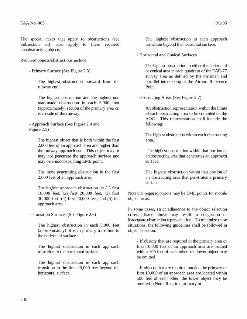
The special cases that apply to obstructions (see The highest obstruction in each approachSubsection 6.3) also apply to these required transition beyond the horizontal surface.nonobstructing objects.
Required objects/obstructions include:
- Primary Surface (See Figure 2.3) or conical area in each quadrant of the FAR-77
The highest obstruction outward from the parallel intersecting at the Airport Referencerunway end. Point.
The highest obstruction and the highest non - Obstructing Areas (See Figure 2.7) man-made obstruction in each 3,000 foot (approximately) section of the primary area on An obstruction representation within the limitseach side of the runway. of each obstructing area to be compiled on the
AOC. This representation shall include the- Approach Surface (See Figure 2.4 and following:Figure 2.5)
The highest obstruction within each obstructingThe highest object that is both within the first area.2,000 feet of an approach area and higher thanthe runway approach end. This object may or The highest obstruction within that portion ofmay not penetrate the approach surface and an obstructing area that penetrates an approachmay be a nonobstructing EME point. surface.
The most penetrating obstruction in the first The highest obstruction within that portion of2,000 feet of an approach area. an obstructing area that penetrates a primary
The highest approach obstruction in: (1) first10,000 feet, (2) first 20,000 feet, (3) first Note that required objects may be EME points for mobile30,000 feet, (4) first 40,000 feet, and (5) the object areas.approach area.
- Transition Surfaces (See Figure 2.6) criteria listed above may result in congestion or
The highest obstruction in each 3,000 feet situations, the following guidelines shall be followed in(approximately) of each primary transition to object selection:the horizontal surface.
The highest obstruction in each approach first 10,000 feet of an approach area are locatedtransition to the horizontal surface. within 100 feet of each other, the lower object may
The highest obstruction in each approachtransition in the first 20,000 feet beyond the - If objects that are required outside the primary orhorizontal surface. first 10,000 of an approach area are located within
2.6.
- Horizontal and Conical Surfaces
The highest obstruction in either the horizontal
survey area as defined by the meridian and
surface.
In some cases, strict adherence to the object selection
inadequate obstruction representation. To minimize these
- If objects that are required in the primary area or
be omitted.
500 feet of each other, the lower object may beomitted. (Note: Required primary or
9/1/96 FAA No. 405
approach objects shall not be omitted because of the - Approximate limits of non-SPHS tiedown areas ifclose proximity of higher objects outside of the permanent tiedown fixtures are present and anyprimary or approach areas). portion of the area is located within 200 feet of a
- When a required object is omitted because of surface. If any portion of the area meets thesecongestion, a replacement object/objects shall be criteria, the entire tiedown area will be delineated. selected if possible that meets the spacing criteria. - Traverse ways, dikes, transmission lines, fence
- Occasionally, additional obstruction information landmark value. may be useful in representing certain obstructingconditions. While rigorous selection criteria is not - A selection of roads, especially in the airportpractical, information useful to obstruction clearing vicinity, to assist the AOC user in geographicactivities should be considered in the selection. orientation.
7. METEOROLOGICAL APPARATUS
Meteorological apparatus is not required unless it is to becarried for its elevation value.
8. PLANIMETRIC DETAIL
Planimetric detail to be provided by AOC surveysincludes the following:
- All usable runways located on the AOC airport.
- Runways with specially prepared hard surfaces thatare not located on the AOC airport but fall within theAP limits on the published AOC.
- Seaplane landing areas when associated with theAOC airport.
- Paved helipads that are isolated from other apronareas. These helipads may or may not be painted ashelipads. Helipads on other apron areas need not beidentified.
- Closed runways if they are sufficiently prominentto be of value to a pilot in airport identification.
- Aprons and taxiways with specially prepared hardsurfaces.
primary or approach obstruction identification
lines, or other linear features having obstruction or
- The terminal building complex, plus hangars,maintenance facilities, and other buildings directlyassociated with aircraft operations and directlyconnected to the apron.
- Approximate limits of obstructing areas.
- Coastlines, lakes, rivers, major highways andbuildings, or other features of landmark value thataid in geographic orientation.
Elevation information is not required for planimetric detailcharted only for its planimetric value. Features selectedfor their elevation as well as their planimetric value, suchas, transmission lines, shall carry a representative spotelevation.
See Subsection 10. for proper depiction of planimetricdetail on AOC survey products.
9. MISCELLANEOUS
AIRPORT REFERENCE POINT
The Airport Reference Point (ARP) shall be computedusing the centerline end positions of all usable runways.However, since runways without specially prepared hardsurfaces are often not required to be surveyed, the ARPposition for these airports will be approximate. The ARPwill be tagged with the year of the most recent runway endsurvey used in the ARP computation, such as, "ARP(1995)."
2.7.

FAA No. 405 9/1/96
Procedures for computing ARP are presented in Appendix published chart shall be either 30x42 or 30x48. The long2. dimension in each case may be either in the north/south or
10. DATA DELIVERY
AOC survey data shall be furnished on the AirportObstruction Chart or in ASCII files in the Universal DataDelivery Format (UDDF)
The content, portrayal, and format for each of theseproducts is presented in this subsection.
10.1. AIRPORT OBSTRUCTION CHART (AOC)
10.1.1. DESCRIPTION
The AOC is a 1:12,000 scale graphic depicting FederalAviation Regulations Part 77 (FAR-77) ObstructionIdentification Surfaces (OIS), a representation of objectsthat penetrate these surfaces, aircraft movement and apronareas, navigational aids, prominent airport buildings, anda selection of roads and other planimetric detail in theairport vicinity. Also included, are tabulations of runwayand other operational data. AOC data is current as of thedate of the field survey.
The AOC consists of four sections:
- Airport Plan (AP)
- Runway Plans and Profiles (RPP)
- Tabulated Operational Data (TOD)
- Notes and Legends (NL)
Contents, portrayal, and general format shall conform tothe style sheet (OC 000) presented in Appendix 7.
10.1.2. MATERIALS AND FORMAT
The AOC shall be published on E50 chart paper, orequivalent, as defined by the Joint Committee on Printing.Border dimensions in inches for the
2.8.
east/west direction, depending on individual chartingrequirements. In addition, approximately 3/4 of an inchshould exist between the border and the paper trim line. Inthose cases where the AP and the RPP will not fit on thefront of the chart, the RPP shall be printed on the chartback. When this front/back format is used, a 1:12,000scale runway layout diagram showing runway numbersand north arrow shall be included on the chart back.
10.1.3. AIRPORT PLAN (AP)
Unless specifically modified because of special chartingrequirements, the AP shall be published at a horizontalscale of 1:12,000. Contents, portrayal, and generalformat shall conform to the style sheet (OC 000)presented in Appendix 7. The following items furtherdefine or clarify certain AP requirements.
10.1.3.1. RUNWAYS/STOPWAYS/BLAST PADS
This subsection lists the requirements for the graphicdepiction of runway data on the AP.
Depiction on the AP depends on surface type and whetheran obstruction survey was accomplished. Depiction shallcomply with the following conventions:
A. Specially Prepared Hard Surface (SPHS) Runwayswith an Obstruction Survey (see Figure 2.10 and Figure2.11)
- Outline solid.
- Length and width labeled in whole feet.
- Surface type labeled "PAVED" if paved and labeled "UNPAVED" for all other surface types.
- Displaced Threshold (DTHLD)
Solid line perpendicular to runway centerline atthe DTHLD but not touching runway outline.

9/1/96 FAA No. 405
Elevation depicted by 1 mm filled circle placedtangent to touchdown side of DTHLD line and - Magnetic Bearing labeled to one decimal place in feet.
Shown in whole degrees with direction arrowLabeled "DISPLACED THRESHOLD" with near each runway end.length labeled to whole feet.
Use leader pointing to DTHLD with label, suchas, "400 FT. DISPLACED THRESHOLD." Shown in their true locations as painted on
- Physical End Elevation number is painted on runway, runway number
Depicted by a 1 mm filled circle placed tangent flight information publication "U.S. Terminalto touchdown side of runway end line Procedures" current at the time of the field
Elevation labeled to one decimal place in feet. of the number approximately 100 feet from the
- Airport Elevation
Depicted by a 1 mm filled circle placed atairport elevation location. Depiction shall be the same as for SPHS runways
Labeled to one decimal place in feet
Elevation enclosed in a solid line box. SPHS) Runways with an Obstruction Survey
- Touchdown Zone Elevation (TDZE) Depiction shall be the same as for SPHS runways
The TDZE shall not be depicted on the AP. dashed and runway always labeled "UNPAVED".(The TDZE shall be indicated in the TabulatedOperational Data section of the AP but only for D. Non-SPHS Runways Without an Obstruction SPHS runways with a landing length equal to, Surveyor greater than, 3,000 feet).
- Supplemental Profile Points with an obstruction survey except outline shall be
Depicted by a 1 mm filled circle on runway airport elevation shall be only elevation pointcenterline. shown.
Selected so that a straight line between any two E. Blast Padsadjacent published runway/stopway points shallnot be greater than one foot from the Outline dashed.runway/stopway surface.
Labeled to one decimal place in feet.
- Runway Numbers
runway at the time of the field survey. If no
published in the United States Government
survey shall be shown on runway with the base
threshold.
B. SPHS Runways Without an Obstruction Survey
with an obstruction survey.
C. Non-Specially Prepared Hard Surface (non-
with an obstruction survey except outline shall be
Depiction shall be the same as for SPHS runways
dashed, runway always labeled "UNPAVED," and
Labeled "BLAST PAD."
Leader used as required in congested areas.
2.9.

FAA No. 405 9/1/96
F. Stopways
Outline dashed
Labeled "PAVED STOPWAY" if paved and as, catenaries, mobile objects, and some cranes, shall be"UNPAVED STOPWAY" for all other surface shown with its EME, as in the following example:types.
Length labeled to whole feet. EME 344"
End elevation depicted with a 1 mm filled circle See Subsection 10.1.3.5. for delineation of linear featuresplaced tangent to runway side of stopway end line as planimetric detail. and labeled to one decimal place in feet.
Leader used as required in congested areas.
Supplemental profile points selected so that a individual obstructions shall be shown. However, in areasstraight line between any two adjacent runway/ considered to be continuously obstructing, such as,stopway points shall not be greater than one foot wooded areas, congested building areas, or ground, thefrom the runway/stopway surface and labeled to one entire obstructing area shall be indicated by andecimal place in feet. obstructing area symbol and a representation of individual
The FAR-77 primary surface terminates at the runway Obstructing Mobile Objects (See Figures 2.8 and 2.9)end for non-SPHS runways and 200 feet beyond thephysical runway end for SPHS runways. The obstructing travel limits of mobile obstructions shall
Short Takeoff and Landing (STOL) runways shall be of the area, as in the following example:treated as other runways except that they shall be labeled"STOL" on the AP. "OBSTRUCTING MOBILE CRANE AREA
10.1.3.2. OBSTRUCTIONS
This subsection lists the requirements for the graphic area shall be subdivided with the appropriate EME notedepiction of obstructions on the AP. applied to each subarea.
Obstructions to be depicted on the AP and special If a nonobstructing mobile object is outward from theconsiderations regarding obstructions are identified in runway end, is higher than the runway end, and is theSubsection 6. highest object in the primary surface or first 2,000 feet of
Obstructions to a FAR-77 specified OIS shall be depicted shall be provided on the AP at the point nearest to thewith a 1 mm filled circle. Obstructions to a supplemental runway centerline end. This EME point forOIS only shall be depicted with an 2 mm open circle and nonobstructing mobile objects shall be a 1 mm opensuperimposed cross. Nonobstructions and objects with no circle.elevation information shall be depicted with a 1 mm opencircle. Obstructing travel limits of vessels shall not be delineated.
2.10.
Estimated Maximum Elevations
Objects with estimated maximum elevations (EME), such
"CATENARY
Obstructing Areas (See Figure 2.7)
In areas of scattered obstructions, a representation of
obstructions within the area shall be shown.
be delineated by a dashed line and labeled with the EME
EME 219"
If different EME's apply to different parts of the area, the
an approach surface, an EME point, without an area limit,
However, the following note shall be

9/1/96
conspicuously placed on the AP cautioning the AOC userof possible obstructing vessels: 10.1.3.4. METEOROLOGICAL APPARATUS
"POSSIBLE OBSTRUCTING VESSEL AREA Meteorological apparatus is not required unless it is to beCONTACT LOCAL AUTHORITIES FOR VESSEL depicted for its elevation value. In this case, it shall be
INFORMATION" treated as other objects.
(See Figure 2.8 and Figure 2.9) 10.1.3.5. PLANIMETRIC DETAIL
Leadered Obstructions This subsection lists requirements for the graphic
Obstructions located beyond the AP limits on the 7 for samples of these depictions.published AOC shall be leadered. Obstructionspenetrating a FAR-77 approach surface, including a Planimetric detail to be depicted in the AP section of thesupplemental surface, and obstructions penetrating the AOC shall include the following:horizontal or conical surface only but located within thelimits of the approach area, shall be leadered from the - All usable runways located on the AOC airport.approach physical end of that runway. All other Runways with specially prepared hard surfaces shallobstructions shall be leadered from the Airport Reference be delineated with a solid line. Runways withoutPoint (ARP). Leadered distances shall be shown to the specially prepared hard surfaces shall be delineatednearest whole foot. with a dashed line. Paved runways shall be labeled
10.1.3.3. NAVIGATIONAL AIDS "UNPAVED."
This subsection lists the requirements for the graphic - Runways with specially prepared hard surfaces thatdepiction of electronic and visual navigational aids are not located on the AOC airport but fall within the(NAVAIDS) on the AP. If the NAVAID is also an AP limits on the published AOC. These runwaysobstruction, Subsection 6. requirements also apply. shall be delineated with a solid line and will include
Both electronic and visual NAVAIDS identified in Subsection 5. and located within the limits of the AP on - Seaplane landing areas when associated with thethe published AOC shall be depicted on the AP and AOC airport. These areas shall be labeledlabeled with the NAVAID type. NAVAIDS located "SEAPLANE LANDING AREA" with nobeyond the limits of the AP on the published AOC shall delineation. not be shown.
The horizontal survey point for electronic NAVAIDS areas. These areas shall be delineated with a solidshall be plotted. The plot point for visual NAVAIDS line and labeled "HELIPAD." Helipads on othershall be plotted. In addition, approach light systems shall apron areas need not be identified.be symbolized between the plot points. (See Subsection5 for visual NAVAID plot points). - Closed runways if they are sufficiently prominent
An elevation shall not be shown unless the NAVAID is Closed runways with specially prepared hardalso to be carried for its obstruction value. In this case, surfaces shall be delineated with a solid line. Closedonly the top elevation shall be shown. runways without specially prepared hard surfaces
If no elevation is indicated, or the NAVAID does not the runway shall be labeled "CLOSED RUNWAY."obstruct, it shall be depicted with a 1 mm open circle. Ifan elevation is shown and the NAVAID obstructs, it shallbe depicted with a 1 mm filled circle. 2.11.
FAA No. 405
depiction of planimetric detail on the AP. See Appendix
"PAVED." All other runways shall be labeled
the airport name if available.
- Paved helipads that are isolated from other apron
to be of value to a pilot in airport identification.
shall be delineated with a dashed line. In both cases

FAA No. 405 9/1/96
- Aprons and taxiways with specially prepared hardsurfaces. These items shall be delineated with a Miscellaneous information to be depicted in the APsolid line. section of the AOC shall include the following:
- Approximate limits of non-SPHS tiedown areas if - The latitude, longitude projection. The projectionpermanent tiedown fixtures are present and any interval for all geographic areas, except Alaska, shallportion of the area is located within 200 feet of a be one minute. In Alaska, the longitude projectionprimary or approach obstruction identification interval shall be two minutes.surface. If any portion of the area meets thesecriteria, the entire area shall be delineated with a - The Airport Reference Point dashed line and labeled "UNPAVED TIEDOWNAREA." - A compass rose oriented to geodetic north showing
- Traverse ways, dikes, transmission lines, fence magnetic variation at the time of the field surveylines, or other linear features having obstruction or shall be labeled along the magnetic arrow to thelandmark value. Feature delineation should be nearest tenth (0.1) of a degree. The official sourcesufficient to allow positive feature identification by for magnetic variation for the AOC and relatedthe chart user. products is the U. S. Geological Survey, Branch of
- A selection of roads, especially in the airportvicinity, to assist the AOC user in geographic - Specified FAR-77 OIS limits dashed. orientation.
- The terminal building complex, plus hangars,maintenance facilities, and other prominent buildings - Runway centerline extended locator depicted.directly associated with aircraft operations anddirectly connected to the apron. These items shall be - Elevation of floor of control tower cab shown in hatched. whole feet.
- Approximate limits of obstructing areas. These 10.1.4. RUNWAY PLANS AND PROFILES (RPP)areas shall be depicted with an obstructing area symbol. The RPP content, portrayal, and general format shall
- Coastlines, lakes, rivers, major highways and Appendix 7. The following items further define or clarifybuildings, or other features of landmark value that certain RPP requirements.aid in geographic orientation.
Elevation information is not required for planimetric detailcharted only for its planimetric value. Features selected The RPP shall be oriented so that for eachfor their elevation value as well as their planimetric value, runway the runway end with the highestsuch as, transmission lines, shall carry a representative longitude shall be to the left on the publishedspot elevation. AOC.
10.1.3.6. MISCELLANEOUS - Scale
This subsection lists the requirements for the graphic Horizontal scale shall be the same as the AP.depiction of miscellaneous information on the AP. Vertical scale shall be 1 inch = 100 feet.
2.12.
both geodetic north and magnetic north arrows. The
Global Seismology and Geomagnetism, Denver CO.
- Supplemental OIS corners ticked and labeled "S."
conform to the style sheet (OC 000) presented in
- Orientation

9/1/96 FAA No. 405
- Area of Coverage surface penetration, and (3) as appropriate to
The extent of the RPP shall be limited to the 2.9)primary and approach surface areas, includingsupplemental approach surface, as depicted in Taxiways and other planimetric detail carried inthe AP. The longitudinal extent of the RPP will the AP shall not be shown in the RPP.depend on obstruction locations in theapproaches and the available space for the RPP Objects that penetrate the approach oron the published AOC. supplemental approach surface of the profiled
The following guidelines should be followed, limits of the RPP shall be leadered from thewhen practical, to determine RPP longitudinal runway end with distances shown to the nearestlimits: whole foot. Objects within the limits of the
- Extend the RPP at least 2,000 feet penetrating the horizontal or conical surfacebeyond the near runway end. only, shall not be leadered.
- Extend the RPP to a 1,000 foot multiple A runway centerline extended locator shall be+ 500 feet, such as, 5,500 feet, 8,500 feet placed in each approach in the Plan portion ofetc. from the opposite runway end. the RPP.
- Extend the RPP at least 500 feet beyond - Content and Portrayal in the Profilethe last obstruction that penetrates theapproach. If this extension is not The profile shall include all objects carried inpractical, the RPP should be terminated at the Plan with spot elevations, including leadereda convenient point that meets the criteria obstructions.above. All approach obstructions locatedbeyond this point shall be leadered with If profiling all objects results in congestion indistances shown to the nearest whole foot. the Profile, lower objects may be omitted.
- Content and Portrayal in Plan be 0.5 inch in length or extend to 0.1 inch
The Plan portion of the RPP shall include: whichever is shorter.
The runway outline The runway, and stopways when present, shall
Objects carried on the AP with a spot with the elevation of each profile point labeled.elevation.
EME points for obstructing mobile object Each Profile shall portray the specifiedareas. (The area but not the EME point is approach surface and supplemental approachshown on the AP). EME point(s) shall be surface, if present. In addition, the Profile forselected at: (1) the point nearest to the specified PIR approaches shall depict a 34:1runway centerline end for primary surface surface in addition to the specified PIR surface.penetrations, (2) the most penetratingpoint for approach
represent the area. (See Figure 2.8 and Figure
runway and are located beyond the published
approach or supplemental approach areas but
The line portrayal of objects in the Profile shall
below the elevation of the runway end,
be depicted in the Profile portion of the RPP
2.13.
FAA No. 405 4/15/98 CHANGE 1
- Object Numbering Scheme requirement applies only to runways with specially
All profiled objects shall be numbered 3,000 feet in length. consecutively from left to right in the Profilewith matching numbers for the corresponding Geodetic azimuth from approach end to stopobjects in the Plan. end, listed to whole seconds. The geodetic
A north arrow shall be placed between each Plan andProfile. Runways with a displaced threshold shall be
When there is insufficient room to print the RPP on the end coordinates listed and a second time withAOC front, the RPP shall be printed on the AOC back. the displaced threshold coordinates listed , allIn these cases, a runway layout diagram, at the scale of carried to four decimal places in seconds.the AP, showing runway numbers and a north arrow shall The runway azimuth shall be carried onlybe included on the chart back. with the physical end listing. The TDZE shall
10.1.5. TABULATED OPERATIONAL DATA listing. (TOD) 10.1.6. NOTES AND LEGENDS (NL)TOD content, portrayal, and general format conform tothe chart sample (OC 000) presented in Appendix 7. The NL content, portrayal, and general format shall conformfollowing items further define or clarify certain TOD to the chart sample (OC 000) presented in Appendix 7.requirements. The following items further define or clarify certain
TOD shall include:
- Airport Location Point (ALP) and legend of the AOC:
Latitude and longitude listed in degrees and - Horizontal datum shown in title boxwhole minutes.
- Airport Reference Point (ARP)
Latitude and longitude listed in degrees,minutes, and one decimal place in seconds. - Airport elevation shown to one decimal place in
- A Runway Data Table (RDT) depicting the feet in the upper left corner of the chart, inside offollowing information for each usable runway: the margin
Runway number - Legend of chart symbols
Latitude and longitude of the approach end - Graphic horizontal scales shown in feet, meters,listed in degrees, minutes, and four decimal nautical miles, and statute miles at the bottomplaces in seconds. center of chart, outside of the margin.
Touchdown Zone Elevation (TDZE) listed to - Graphic vertical scale shown at lower right cornerone decimal place in feet. This of chart inside of the margin.
2.14.
prepared hard surfaces equal to, or greater than,
azimuth shall be reckoned from north.
listed twice, once with the runway physical
be carried only with the displaced threshold
notes and legend requirements.
The following information shall be included in the notes
- Vertical datum shown in title box
- Map projection shown in title box

9/1/96 FAA No. 405
- AOC edition number shown at lower left corner of - Publication credit shown at lower center of chart,chart, outside of the margin. outside of the margin.
- Date of survey shown at lower left corner of chart, - "National Ocean Service" shown at upper right ofoutside of the margin. chart, outside of the margin.
- Date of publication shown at lower left corner ofchart, outside of the margin.
- Data source paragraph shown at lower left cornerof chart, outside of the margin.
- Amendment data box shown at lower left corner ofchart, inside of the margin.
- Airport name and associated city and state shownin upper center and lower right of chart, both outsideof the margin.
- AOC number shown in upper left and lower rightof chart, outside of the margin.
- Department of Commerce logo shown in uppercenter of chart, inside of the margin.
10.2. UNIVERSAL DATA DELIVERY FORMAT
10.2.1. DESCRIPTION
The Universal Data Delivery Format (UDDF) is a digitaldelivery system which provides aeronautical and otherdata, including airport, runway, navigational aid,and obstruction information in a standard ASCII format.This information can be easily read into user data filesand data bases.
10.2.2. CONTENT AND FORMAT
General UDDF content, portrayal, and format informationare presented in Appendix 1.
2.15.


THIS FIGURE EXPLAINS OR CLARIFIES CERTAINDATA REQUIREMENTS - SEE TEXT AND STYLE SHEETOC 000 FOR COMPLETE STANDARDS DIMENSIONS ARE IN FEET
NOT TO SCALE
FAA NO. 4059/1/96
FIGURE 2.10THRESHOLD, STOPWAY, BLAST PAD, AND
RUNWAY NUMBER DEPICTIONS ON THE AIRPORT PLAN
RUNWAY NUMBERS SHALL BE DEPICTED ASPAINTED ON THE RUNWAY AT THE TIME OF THEFIELD SURVEY. IF A NUMBER IS NOT PAINTED ONTHE RUNWAY, THE RUNWAY NUMBER PUBLISHEDIN THE “U.S. TERMINAL PROCEDURES” CURRENTTHE TIME OF THE FIELD SURVEY WIL BE DEPICTEDWITH THE BASE OF THE NUMBER APPROXIMATELY100 FEET FROM THE THRESHOLD.
STOPWAY SURFACE TYPE SHALL BE LABELED“PAVED” FOR PAVED SURFACES AND“UNPAVED” FOR ALL OTHER SURFACE TYPES
DISPLACED THRESHOLD AND STOPWAYLENGTHS SHALL BE LABELED IN WHOLE FEET
700 FT. DISPLACED THRESHOLD
BLAST PAD
LEADERS MAY BE USED AS REQUIRED WITHBLAST PADS AND STOPWAYS - ALWAYSLEADER DISPLACED THRESHOLDS
RELOCATED THRESHOLD DISPLACED THRESHOLD
BLAST PAD(ALWAYS DASHED)
STOPWAY(ALWAYS DASHED)

THIS FIGURE EXPLAINS OR CLARIFIES CERTAINDATA REQUIREMENTS - SEE TEXT AND STYLE SHEETOC 000 FOR COMPLETE STANDARDS DIMENSIONS ARE IN FEET
NOT TO SCALE
9/1/96
FIGURE 2.11RUNWAY LENGTH AND SURFACE
TYPE DEPICTIONS ON THE AIRPORT PLAN
FAR - 77 PRIMARY SURFACE ENDS200 FEET BEYOND RUNWAY FORSPHS RUNWAYS AND AT RUNWAYEND FOR NON-SPHS RUNWAYS
RUNWAY OUTLINE SHALL BE SOLIDFOR SPECIALLY PREPARED HARDSURFACES (SPHS) AND DASHED FOROTHER SURFACES
RUNWAY SURFACE TYPE SHALL BE LABELED“PAVED” FOR PAVED SURFACES AND“UNPAVED” FOR OTHER SURFACE TYPES
RUNWAY LENGTH AND WIDTH SHALL BELABELED IN WHOLE FEET
4,500 X 150 PAVED
4,500 X 150 UNPAVED
4,500 X 250 UNPAVED
FAA NO. 405

This document has been divided into 2 parts for ease of downloading. Refer to Part 2 to view the rest of this document.