Table of Contents Tire Pressure Warning Systems Tire Pressure Warning Systems Set/Push Button Switch...
21
Initial Print Date:1/03 Revision Date: Subject Page Purpose of the System ........................................................................3 System Components ............................................................................5 DSC III Module .....................................................................................5 RDW Module ........................................................................................5 Pushbutton Switch ...............................................................................6 Check Control Display ............................................................................7 Principle of Operation ..........................................................................8 Initialization ...........................................................................................9 E85 Initialization ....................................................................................10 Diagnosis ...............................................................................................11 Run Flat Tire Technology .....................................................................12 RDC Tire Pressure Control (E65/E66) .................................................14 Components .........................................................................................15 RDC Control Unit ................................................................................15 Receiving Antennae .................................................................. ...........15 Wheel Transmitter Modules ..................................................................16 Principle Of Operation .........................................................................17 Initialization ...........................................................................................17 Tire Pressure Monitoring ............................................................. .........18 Tire Pressure Warning ..........................................................................19 Review Questions ................................................................................ 20 Table of Contents Tire Pressure Warning Systems
Transcript of Table of Contents Tire Pressure Warning Systems Tire Pressure Warning Systems Set/Push Button Switch...

Initial Print Date:1/03 Revision Date:
Subject Page
Purpose of the System ........................................................................3
System Components ............................................................................5DSC III Module .....................................................................................5RDW Module ........................................................................................5Pushbutton Switch ...............................................................................6Check Control Display............................................................................7
Principle of Operation ..........................................................................8Initialization ...........................................................................................9E85 Initialization ....................................................................................10
Diagnosis ...............................................................................................11
Run Flat Tire Technology .....................................................................12
RDC Tire Pressure Control (E65/E66) .................................................14
Components .........................................................................................15RDC Control Unit ................................................................................15Receiving Antennae .................................................................. ...........15Wheel Transmitter Modules ..................................................................16
Principle Of Operation .........................................................................17Initialization ...........................................................................................17Tire Pressure Monitoring ............................................................. .........18Tire Pressure Warning ..........................................................................19
Review Questions ................................................................................ 20
Table of Contents
Tire Pressure Warning Systems

2Tire Pressure Warning Systems
Model:
Production: Start of Production MY
Objectives:
After completion of this module you should be able to:
• Identify Components in Tire Pressure Warning Systems
• Diagnose Tire Pressure Warning Systems
• Initialize Tire Pressure Warning Systems

3Tire Pressure Warning Systems
Tire Pressure Warning Systems
Purpose of the System
The Tire Pressure Warning System (RDW) is being introduced for the US market on the newE39 M5. RDW is the German acronym for “Reifen Druck Warnen” and it follows the tirepressure control system (RDC) that has been in use in other markets for several years. TheRDW and RDC systems will eventually be linked to the run flat tires as a means of warn-ing the driver of pressure losses in the tires.
Experience has shown that the majority of owners are unaware that the owner’s manualrecommends that the inflation pressure be checked at 14 day intervals. The RDW systemwill aid in this by warning the driver of pressure losses in one or more of the tires.
Consequences of incorrect inflation pressures result in:
• Increased tire wear• Reduced service life of the tires• Impaired vehicle handling• Increased risk of punctures due to worn tread
Regardless of the terminology used, the Tire Pressure warning system is designed to warnthe driver of pressure losses in one or more of the tires through the “Check Control” display(or Warning Light)
The system measures the wheel speeds of all four tires and compares the speed of thediagonal wheels for the average speed. A rolling circumference value is calculated from thewheel speeds and this value is stored in the control module.
In the event of pressure loss, the rolling circumference of the affected tire is reduced . Withthis, the wheel speed of the tire increases and the control module will detect the changeand post the warning in the Check Control matrix display or will display a waring light in theinstrument cluster.
An additional acoustical warning is sounded if the pressure loss is greater than 40%.
The tire pressure warning system is switched “ON” every time the ignition is switched “ON”and it can be switched OFF with the button on the lower dash to the right of the steeringcolumn.
NOTE: The system can only react to the pressures in the tires when thesystem is initialized, it cannot check for the correct inflation pressure.

4Tire Pressure Warning Systems
Tire Pressure Warning Systems have 2 basic configurations:
• Systems which uses wheel speed sensor input to detect rotational irregularities to determine pressure loss. The systems either use a separate RDW module which rreceives individual wheel speed input from the DSC module or the RDW functions are incorporated directly into the DSC electronics. These systems have numerousacronyms to identify them depending upon model and production date etc.
Some of the acronyms currently in use are:
• RDW - This system is usually associated with the E39 M5 and E46 M3.• RPA - This term is currently used on the E85 and E46 (from 2001).• DDS - Tis acronym can sometimes be found when using the diagnosis pro
gram with the DISplus or GT-1.• DWS - This system was installed on the E52 Z8.
• Systems which use pressure transmitters located inside the tire assembly. These transmitters send signals to external antennae at all 4 wheels. Currently, the only USmarket vehicle to use this system is the E65/E66. This system will be covered laterin this text. These systems are generally referred to as RDC and use Run Flat Tire Technology (RFT).

5Tire Pressure Warning Systems
System Components
The tire pressure warning system consists of the following components:
• RDW Module (On early systems only, deleted as of 2001 MY)
• DSC Module
• Wheel Speed Sensors
• RDW/RPA Button
• Warning Indicator (Cluster Check Control or Warning Indicator lamp)
DSC III Control Module / Wheel Speed Sensor
The four wheel speed sensor inputs are processed by the DSC control module and fourdedicated square wave output signals are provided to the RDW control module for its pro-cessing functions.
RDW Control Module
The RDW control module was only used on the early production models such as the E39M5 and the E52 Z8. All RDW modules have been eliminated as of the 2001 model year.The newer systems incorporate the RDW functions into the DSC module, this eliminatesthe need for a separate RDW module.
The RDW control module is located behind the glove box in the control module carrier. inaddition to the four wheel speed signals, the module receives power (KL 15), ground (KL31) and a ground signal input from the set/push button switch in the console.
The control module is connected to the K-Bus for:
• Output display in the check control matrix or Warning Light
• Diagnostic communication through the instrument cluster with the DISplus tester or GT-1.
The control module processes the wheel speed signals and stores rolling circumferencevalues for determining pressure losses in one or more tires.

6Tire Pressure Warning Systems
Set/Push Button Switch
The push button (with tire failure symbol) is mounted below the instrument cluster to theright of the steering wheel. The push button is used to carry out the following functions:
• Initialization of the system - after changing inflation pressures or tires.
• Switching the RDW system OFF - After switching the ignition switch ON, briefly press the button “TIRE MONITORING INACTIVE” will be displayed in the matrix.
• Self diagnosis of the control module (only for manufacturing purposes) - however if thepush button is pressed and held while switching the ignition ON, “TIRE PRESSURE INACTIVE” will be displayed in the matrix.
!RDW Button (M5)
RDW/RPA Button (E85)

7Tire Pressure Warning Systems
Check Control Display
The check control display is used to show the operating status of the RDW system. Thedisplays are as follows:
• “TIRE PRESSURE FAILURE” - (with an acoustic warning) this display will remain activeuntil the ignition is switched OFF.
• “TIRE PRESSURE SET” - Will be displayed when the system is put intothe initialization mode.
• “TIRE MONITORING INACTIVE” - Will be displayed when the system is manually switched OFF or there is a system fault.
8Tire Pressure Warning Systems
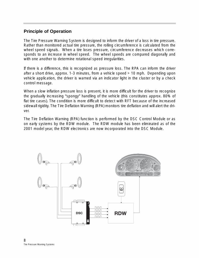
Principle of Operation
The Tire Pressure Warning System is designed to inform the driver of a loss in tire pressure.Rather than monitored actual tire pressure, the rolling circumference is calculated from thewheel speed signals. When a tire loses pressure, circumference decreases which corre-sponds to an increase in wheel speed. The wheel speeds are compared diagonally andwith one another to determine rotational speed irregularities.
If there is a difference, this is recognized as pressure loss. The RPA can inform the driverafter a short drive, approx. 1-3 minutes, from a vehicle speed > 10 mph. Depending uponvehicle application, the driver is warned via an indicator light in the cluster or by a checkcontrol message.
When a slow inflation pressure loss is present, it is more difficult for the driver to recognizethe gradually increasing “spongy” handling of the vehicle (this constitutes approx. 80% offlat tire cases). The condition is more difficult to detect with RFT because of the increasedsidewall rigidity. The Tire Deflation Warning (RPA) monitors tire deflation and will alert the dri-ver.
The Tire Deflation Warning (RPA) function is performed by the DSC Control Module or ason early systems by the RDW module. The RDW module has been eliminated as of the2001 model year, the RDW electronics are now incorporated into the DSC Module.

9Tire Pressure Warning Systems
Initialization
The RDW system must be initialized to allow the control module to adopt the wheel speedsignals and set the rolling circumferences in its memory. Initialization must be carried outwhen:
• Tire inflation pressures are changed.• New tires are installed.• The control module or wheel speed sensors are changed.
The initialization process is started by pressing the push button >4 seconds (Tire PressureSet will be displayed in the matrix). The system is now in the learn mode and after drivingoff, the control module will start to store the values for the rolling circumferences of the tiresbased on the road speed.
For leakage detection, three different speed ranges are taken into account and must berecognized by the control module to complete a full initialization process. The control mod-ule must receive useable speed signals for a cumulative total of 4 to 15 minutes depend-ing on the speed range.
Once a speed range is set, the control module will then monitor that speed range for andpressure losses. The system can only display a pressure loss warning, it can not display theexact tire with the pressure loss. All tires need to be checked when the warning is displayedin the matrix.
NOTE: Not all speed ranges need be set for the system to function properly.

10Tire Pressure Warning Systems
Initialization
Under certain driving conditions the control module will not evaluate the wheel speed sen-sors as false warnings could be triggered. These conditions include:
• Initialization in a speed range that has not been complete• During rapid acceleration• Severe (heavy) braking• High speed cornering• Road speeds < 7MPH• High slip differentials between individual wheels
No Warning Conditions
The system can only detect pressure differences between tires, it can not measure absolutepressure. The system can not detect the following:
• Natural diffusion that occurs on all tires equally• A tire blow out• Pressure loss at the rear axle at speeds > 90 MPH
E85 Initialization/Operation
The system must be initialized when the tire inflation pressures are changed or when thewheels/tires are replaced.
The RPA switch (1) in the center console switching center must be pressed to start initial-ization.
With KL15 “on”, press the RPA switch until the RPA indicator light in theInstrument Cluster illuminates in “yellow”.
After a a short drive (approx. 1-3 minutes), from a vehicle speed > 10 mph, the systemlearns the new wheel speed sensor reference values and the RPA indicator light (yellow)goes out.
When an inflation pressure loss is determined, the RPA indicator light illuminates in “red”.The driver is informed of a RPA system failure by the “yellow” illuminated RPA indicator light.
11Tire Pressure Warning Systems
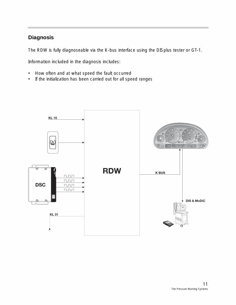
Diagnosis
The RDW is fully diagnoseable via the K-bus interface using the DISplus tester or GT-1.
Information included in the diagnosis includes:
• How often and at what speed the fault occurred• If the initialization has been carried out for all speed ranges

12Tire Pressure Warning Systems
Run Flat Tire (RFT) Technology
Purpose of the System
BMW Run Flat Tire (RFT) Technologywhich was first introduced on the Z8,is standard on the E85 (Z4). RFTtechnology offers large advantagesto the customer in dynamic stabilitywith slow or sudden air pressure lossand Deflation Warning. In addition,the spare wheel and jacking equip-ment in the trunk is deleted whichprovides additional storage space.
A tire with back up running ability(RFT) will be differentiated from anon-run flat tire by the encircled letterdesignation on the sidewall (forexample: RSC - RRunflat SSystemCComponent).
Principle of Operation
If slow or sudden inflation pressure loss occurs in a RFT, it is still mobile because of theadditional high temperature rubber reinforcements that strengthen the side wall.
These reinforcements prevent side wall damage when the tire is deflated and also providessupport during extreme loads (even when negotiating curves). In addition, the special RFTwheel (rim) grips the tire for sufficient steering, braking and accelerating power.
NNoottee::- With a sudden inflation pressure loss the vehicle can be driven with
a maximum speed of 50 mph for a maximum distance of approx. 100 miles.
- With a slow inflation pressure loss the vehicle can be driven with a maximum speed of 50 mph for a maximum distance of approx. 1200 miles.
- A winter profile RFT will also be offered.
- In an extreme case, standard tires can be temporarily substituted on the samewheel (rim) if RFT is not available.
13Tire Pressure Warning Systems
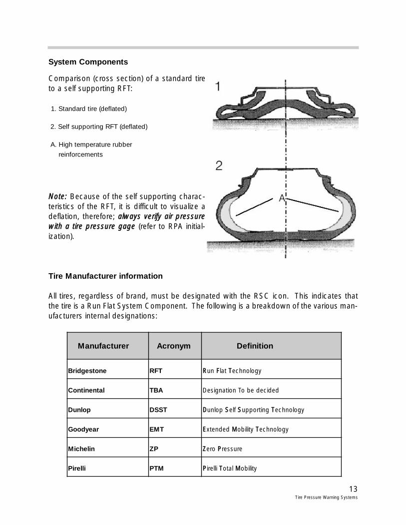
System Components
Comparison (cross section) of a standard tireto a self supporting RFT:
1. Standard tire (deflated)
2. Self supporting RFT (deflated)
A. High temperature rubber
reinforcements
NNoottee:: Because of the self supporting charac-teristics of the RFT, it is difficult to visualize adeflation, therefore; aallwwaayyss vveerriiffyy aaiirr pprreessssuurreewwiitthh aa ttiirree pprreessssuurree ggaaggee (refer to RPA initial-ization).
Tire Manufacturer information
All tires, regardless of brand, must be designated with the RSC icon. This indicates thatthe tire is a Run Flat System Component. The following is a breakdown of the various man-ufacturers internal designations:
Manufacturer Acronym Definition
Bridgestone RFT RRun FFlat TTechnology
Continental TBA Designation To be decided
Dunlop DSST DDunlop SSelf SSupporting TTechnology
Goodyear EMT EExtended MMobility TTechnology
Michelin ZP ZZero PPressure
Pirelli PTM PPirelli TTotal MMobility

14Tire Pressure Warning Systems
RDC Tire Pressure Control (E65/E66)
Purpose of System
RDC is an available option for the E65. The system monitors the tire inflation pressures,both when the vehicle is being driven and when it is stationary.
An electronic transmitter module mounted inside each tire measures the tire pressure andtemperature at regular intervals and transmits the information by radio frequency to theRDC control unit.
The driver is warned with a Check Control message of a tire that needs inflation or a pos-sible flat tire.
System Overview E65/E66

15Tire Pressure Warning Systems
Components
RDC Control Unit
The RDC control unit is located behind the glove box on the equipment carrier above theZGM.
The control unit is connected to the K-CAN System bus.
The RDC control unit is responsible for monitoring the individual pressures and tempera-tures of the tires (including the spare). If one of the tires inflation pressure falls below a spe-cific threshold then the RDC generates a CC warning and telegrams it over the K-CAN-S.
The Instrument Cluster displays the check control warning icon and text message accord-ing to the message sent. The Control Display is informed by the Instrument Cluster of therequired extended message.
Receiving Antennas
The RDC antennas are located behind thesplash shield of each of the four wheel hous-es.
The antennas receive the radio signals fromthe RDC transmitters and pass the signalsalong a shielded cable to the RDC control unit.

16Tire Pressure Warning Systems
Wheel Transmitter Modules
The transmitter modules are located inside the tireattached to the valve stem. The modules contain apressure and temperature sensor, a long life 3.6Vlithium battery and a radio transmitter.
• Operating frequency for the U.S. : 315Mhz
• Battery life: 5 to 7 years
The transmitter modules are active in an energy saving mode even when they are sitting asspare parts on the shelf.
Each transmitter module has it’s own unique I.D. code. The I.D. code is assigned to a posi-tion on the vehicle (Right rear, left front etc.) after a successful initialization has been com-pleted.
The radio signal transmitted by the wheel modules is received when the tire passes closeto the antenna. The valve stem of the spare tire should be pointed towards the right rearwheel house because the spare is also included in the monitoring (although it is not dis-played on the CD).
The wheel transmitter module measures its ambient air pressure every minute. If the airpressure increases by 0.5 bar between measurements , the transmission rate increases toevery 0.8 seconds.
If the increase in air pressure is detected for approximately 216 seconds, the full function-ality of the wheel module is activated. If the higher pressure then continues, the moduleremains permanently active and measures the air pressure and temperature every 0.3 sec-onds and transmits the information by radio signal every 55 seconds.
At temperatures over 120oC the transmitter modules are switched off. Once the transmit-ter cools to below 110oC operation resumes.
17Tire Pressure Warning Systems
Principle of Operation
Initialization
After the tires are replaced, rotated or if their inflation pressures are adjusted, then the wheeltransmitter modules must be initialized using the RDC function in the “Settings” menu of theControl Display.
During initialization the following processes are performed:
• Individual wheel recognition (Identification of wheel transmitter modules).
• Wheel position assignment.
• Plausibility check (setpoint pressures checked).
• Adoption of setpoint pressures as specified pressures.
The RDC then learns the wheel transmitter module position.
The minimum air pressure accepted by the RDC on initialization is 1.7 bar (24.7psi). If thetire pressures deviate more than 0.4 bar (6psi) per axle the initialization is rejected after aplausibility check.
1.3 bar is the lowest pressure detected by the wheel transmitter module. At that point, atire failure warning will always be issued.
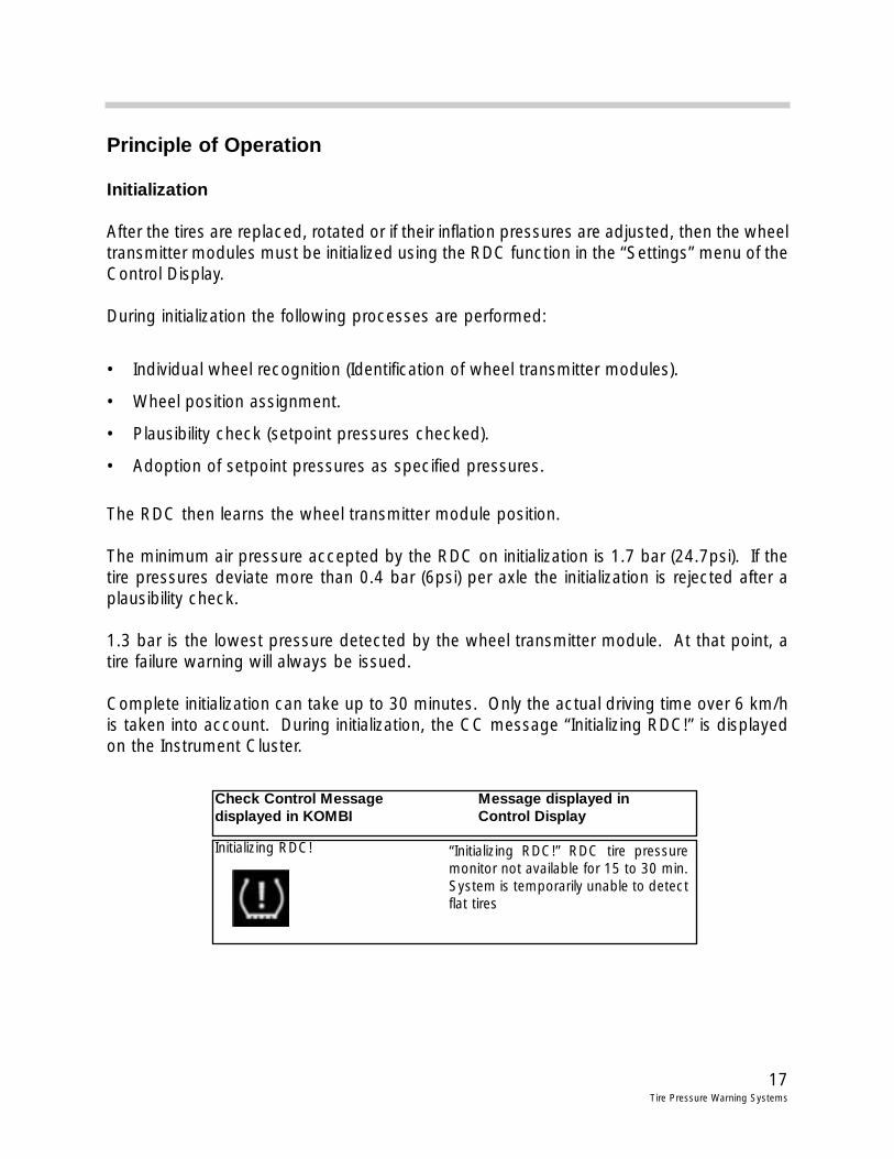
Complete initialization can take up to 30 minutes. Only the actual driving time over 6 km/his taken into account. During initialization, the CC message “Initializing RDC!” is displayedon the Instrument Cluster.
Initializing RDC!
Check Control Message Message displayed in displayed in KOMBI Control Display
“Initializing RDC!” RDC tire pressuremonitor not available for 15 to 30 min.System is temporarily unable to detectflat tires

18Tire Pressure Warning Systems
When the initialization from the Control Display is activated, the wheels appear black andthe pressures are not shown.
Once initialization is complete, the tires of the car on the graphic turn green and pressurevalues are shown for each tire.
Tire Pressure Monitoring
During monitoring, the RDC control unit takes the measured temperature and pressure anddetermines a target pressure value.
If the tire pressure being monitored falls below the required level by 0.2 bar for more than8 minutes, a CC message appears on the instrument cluster after the car is started. Thedriver is prompted to to check the tire pressure.
• “Autumn warning”: If the tire temperature is 20oC lower for 14 days than the temperature was when the RDC was last initialized the RDC will also warn the driver tocheck the tire pressures.
When the RDC menu on the Control Display is activated, the car is shown with yellow tires.
The tire pressures must be adjusted and an initialization carried out.
Check tire pressures!
Check Control Message Message displayed in displayed in KOMBI Control Display
“Check tire pressures!”Check tire inflation pres-sures; refer to owners man-ual or inflation chart.

19Tire Pressure Warning Systems
Tire Failure Warning
If a tire being monitored falls below the specified level by 0.4 bar after temperature calcula-tion or 16% of the inflated pressure then a CC message appears on the instrument clusterwith an audible warning tone. A message also appears on the Control Display.
When the RDC menu on the Control Display is activated, the car is shown with the defec-tive tire in red. In the case of a spare tire failure, all wheels are shown in red.
Once the tire pressures are restored to the setpoint in the RDS control unit the tires of thecar graphic in the Control Display return to green and the Check Control message is with-drawn.
See the chapter “E65 Instrument cluster” for details on additional Check Control messages.
Flat tire! stop vehiclecarefully.
Check Control Message Message displayed in displayed in KOMBI Control Display
Left front tire is flat, refer to ownersmanual or contact BMW Roadsideassistance.

20Tire Pressure Warning Systems
Review Questions
1. Where are the transmitters and antennas located for the RDC system on the E65/E66?What is the operating frequency for the U.S.?
2. What conditions cause the wheel transmitter units to go from energy saving mode to fullfunctionality?
3. When adjusting tire pressures on a vehicle equipped with RDC, what is the maximum difference between tires of the same axle allowed by the system?
4. When is initialization of the RDC system necessary? Explain briefly what the system isdoing during the learning process.
5. How does the RDW/RPA system detect pressure loss in the tire?
6. What conditions are NOT detected by the RDW/RPA system?
7. When should initialization be carried out the RDW/RPA system?
8. What designation should be common to ALL run flat tires?
21Tire Pressure Warning Systems