
TABLE OF CONTENTS - StraightLine HDD · The StraightLine AH system is a pneumatic-percussive hammer...
61
i TABLE OF CONTENTS I INTRODUCTION System Diagram................................................................................ II INSTALLATION AND OPERATION 1. Safety .......................................................................................... 2. Down Hole Assembly ..................................................................... 3. Breakout Wrench Kit..................................................................... 4. Setup of Hammer ........................................................................ 4a. Choke............................................................................... 4b. Bent Sub........................................................................... 5. Setup of Transmitter ...................................................................... 5a. DCI................................................................................... 5b. Subsite............................................................................. 6. Installation of Bit.......................................................................... 7. Setup of Support Pack/ No Air Pressure.......................................... 7a. Install Whip Check/ Air Inlet/ Compressor ............................ 7b. Install Whip Check/ Air Outlet/ Rig...................................... 7c. Tri-Lite Valve controller ....................................................... 7d. Fluid Pump Setup............................................................... 7e. Oil Properties and Tank Filling............................................. 8. Setup of Support Pack/ Air Pressure Applied................................... 8a. Setup of Air Compressor ..................................................... 8b. Pressure Regulator Setup/ Adjustment................................ 8c. Oiler Adjustment................................................................ 8d. Water Pump Adjustment/ Operation.................................... 9. Air Hammer Operation.................................................................. 9a. Setting Up (on site)............................................................ 9b. Attaching the down hole assembly ....................................... 9c. Setting up for operation...................................................... 9d. Thrust Pressure for Drilling and Steering.............................. 9e. Steering the StraightLine Air Hammer .................................. 9f. Maintaining a Clean, Round Hole......................................... 9g. Drilling Straight.................................................................. 9h. Cleaning and Storage after Each Use................................... III APPENDIX: Exploded Parts/ Breakout Wrenches/ Tool Kit..................... 1 2 3 3 6 7 8 9 9 17 19 23 24 25 25 28 29 34 34 34 35 37 39 39 39 39 40 40 41 41 42 43
Transcript of TABLE OF CONTENTS - StraightLine HDD · The StraightLine AH system is a pneumatic-percussive hammer...

i
TABLE OF CONTENTS
I INTRODUCTION System Diagram................................................................................
II INSTALLATION AND OPERATION 1. Safety.......................................................................................... 2. Down Hole Assembly..................................................................... 3. Breakout Wrench Kit..................................................................... 4. Setup of Hammer........................................................................ 4a. Choke............................................................................... 4b. Bent Sub........................................................................... 5. Setup of Transmitter...................................................................... 5a. DCI................................................................................... 5b. Subsite............................................................................. 6. Installation of Bit.......................................................................... 7. Setup of Support Pack/ No Air Pressure.......................................... 7a. Install Whip Check/ Air Inlet/ Compressor............................ 7b. Install Whip Check/ Air Outlet/ Rig...................................... 7c. Tri-Lite Valve controller....................................................... 7d. Fluid Pump Setup............................................................... 7e. Oil Properties and Tank Filling............................................. 8. Setup of Support Pack/ Air Pressure Applied................................... 8a. Setup of Air Compressor..................................................... 8b. Pressure Regulator Setup/ Adjustment................................ 8c. Oiler Adjustment................................................................ 8d. Water Pump Adjustment/ Operation.................................... 9. Air Hammer Operation.................................................................. 9a. Setting Up (on site)............................................................ 9b. Attaching the down hole assembly....................................... 9c. Setting up for operation...................................................... 9d. Thrust Pressure for Drilling and Steering.............................. 9e. Steering the StraightLine Air Hammer.................................. 9f. Maintaining a Clean, Round Hole......................................... 9g. Drilling Straight.................................................................. 9h. Cleaning and Storage after Each Use...................................
III APPENDIX: Exploded Parts/ Breakout Wrenches/ Tool Kit.....................
1
2336789917192324252528293434343537393939394040414142
43

ii

I INTRODUCTION
The System:The contents of this manual apply to StraightLine’s AH 4.0 & 5.0 hammer systems.
The StraightLine AH system is a pneumatic-percussive hammer system designed for directional drilling in rock formations. The system consists of these key elements: 1) down hole assembly; 2) support pack with water tank; 3) breakout wrench kit [optional]; 4) hoses and related fittings.
To conduct a directional bore, the air hammer system is installed on a HDD rig (size range 10,000 to 80,000 pounds of thrust), and then connected to an air compressor capable of producing a minimum of 400 cfm (11.3 cmm) and a maximum operating pressure of 350 psi (20.68 bar). The integration of all these elements is shown in the diagram below (Fig 1).
System Diagram(Fig. 1)
This manual contains safety and operational information for the air hammer system. You must read this manual and fully understand the safety precautions and operating procedures before operating the air hammer system.
1

2
II AH4.0 AIR HAMMER INSTALLATION AND OPERATION
1. SAFETY: Consult the safety section in your HDD manualUtilization of this equipment must be conducted under safe working conditions at all times. Observe all safety guidelines as directed by your employer, job site requirements, and State and Federal regulation.
This safety alert symbol means SAFETY ALERT! This symbol is used both on the machine and in this manual to alert the operator that the message following the symbol concerns safety. Carefully read the message and make sure you understand the causes of possible injury or death. The safety alert symbol will be used with these words: DANGER: Indicates an imminently hazardous situation, which will result in death or serious injury unless avoided. WARNING: Indicates a potentially hazardous situation, which could result in death or serious injury unless avoided.
CAUTION: Indicates a potential hazardous situation, which may result in minor or moderate injury if not avoided. NOTICE: Indicates a situation which could result in damage to the machine or other property. Other important information which can help you do a better job or simplify maintenance, will be emphasized by the word: IMPORTANT: followed by an instruction or information.
WARNING Entanglement Hazard Loose fitting clothing can become entangled in rotating equipment. Wear close fitting clothing and safety equipment appropriate to the job.
WARNING Hearing Damage Wear ear protection to prevent hearing damage caused by percussive equipment.
WARNING Flying Debris Hazard Wear eye protection to prevent eye damage caused by flying debris.
WARNING Heavy Equipment Assembled air hammer assembly weighs in excess of 100 pounds. Use a suitable lifting device to move equipment.
WARNING Severing Hazard Moving components can sever fingers and hands. Keep clear of all moving components.

3
Other important safety alerts may appear throughout this manual and on safety alert decals located on the support pack.
2. DOWN HOLE ASSEMBLY COMPONENTS
Your down hole components, as shipped, consist of the following: drill pipe adapter, transmitter housing assembly, bent sub, air hammer, chuck, and bit. The illustration below shows the method of joining the components, showing which parts should be lubricated threads and which connections should be locked with thread locking compound (see Fig 2).
(Fig. 2)
3. BREAKOUT WRENCHProper use of the StraightLine Breakout Wrench KitIn order to properly “make up” or “break out” the tool joints when attaching air hammer threaded components to each other, or the drill string, always use the available Straight-Line breakout wrench kit, or an equivalent (see Fig. 3).
WARNING Rotating Parts Never use rig power or other powered equipment when making up or breaking out threaded connections.
Serious injury or death may result from rotating parts or from thrown wrenches.
StraightLine Breakout Wrench Kit(Fig. 3)

4
1. Thread the two components together by hand until the joint is hand tight. (see Fig 4).
(Fig. 4)
2. Attach wrench handle to first component (see Fig. 5, 6).
(Fig. 5)
(Fig. 6)

5
3. Assemble StraightLine Breakout Wrench Kit as illustrated (see Fig 7,8,9).
(Fig. 7)
4. Turn the spinner handle until the two components make full shoulder contact, then continue to turn for 1/4 to 1/2 revolution. The joint is now properly tightened (see Fig. 10, 11).
Fig. 8 Fig. 9
Fig. 10Fig. 11

6
5. In order to “Break” a joint free, follow the preceding steps in the same order, but turn the spinner handle in the opposite direction, so that the two components unthread (see Fig 12).
Fig. 12
4. HAMMER SETUP4a. Installation of Choke Into the Air Hammer (see Appendix for full parts breakdown of air hammer assembly)
IMPORTANT: Before initial drilling with a new hammer, pour 1 pint (1/2 litre) of Rock Drill Oil into the back of the hammer housing (see figure 48 for oil selection). Then reassemble hammer to bent sub. Coat threads with thread locking compound; tighten to hand tight then use breakout makeup wrench kit to tighten 1/4 to 1/2 turn beyond shouldering.
For optimum percussive performance of the air hammer, the operational pressure of the hammer needs to match that of the supply air of the compressor. Do not exceed 350 psi of operating pressure at the air hammer. Operating over 350 psi will increase penetration rates, but reduce service life of the tool. To maintain the optimum pressure, chokes are used to control the amount of air driving the piston of the air hammer. The choke selection depends on the compressor specifications and the length of the bore.
Your air hammer is supplied with the FULL choke installed. To change the choke, use a nail set to drive out the full choke plug in the check valve (see Fig. 13). Insert the choke plug of choice (see Choke Selection Chart, Fig. 14) then assemble the air hammer body to the bent sub.

7
Fig. 13
Choke Selection ChartThere are several variables which determine the performance of the air hammer. The examples below generally explain the choice of choke to use in various situations.
Fig. 14

8
4b. Assemble bent sub to Air Hammer Housing Clean and dry the threads. Apply thread locking compound to the threads (be careful not to get locking compound on the bent sub o-ring). Insert the bent sub into the air hammer housing (the end opposite the chuck) and rotate clockwise until the shoulders make full contact. Use the breakout makeup wrench kit to turn 1/4 to 1/2 revolution beyond full shoulder contact.
IMPORTANT: The bent sub must be installed with the counter-bored end threaded into the air hammer housing - not the star-milled end (see Fig. 16).
Fig. 15
Fig. 16

9
5. SETUP OF TRANSMITTER Before continuing with the installation and setup of the transmitter, the transmitter housing must first be assembled to the bent sub.
Coat the threads of the star-milled end of the bent sub with thread locking compound (avoid getting compound on the bent sub o-ring). Thread the transmitter housing onto the bent sub until it is hand tight. Use the breakout makeup wrench kit to rotate 1/4 to 1/2 turn beyond shoulder contact (see Fig. 17).
NOTE: For correct orientation of the transmitter housing, elongated slots in the transmitter housing wall are located closest to the downhole end of the housing.
Fig 17
Your air hammer is supplied with the necessary parts to install a DCI® brand transmitter (standard). An optional model is also available for installing a Subsite® brand beacon.
5a. DCI® transmitter is installed as follows (see Transmitter Exploded Parts in the appendix):
1. Cradle the downhole assembly horizontally on a work surface.
2. Unscrew the outer transmitter tube clocking cap from the outer transmitter tube, then slide out all components, as shown in the illustration (Fig 18 and 19).

10
Fig. 18
3. Remove inner transmitter tube clocking cap, as shown, from the inner transmitter tube housing.
Insert DCI transmitter (with fresh lithium ion battery), battery end first, into inner transmitter tube housing.
Align notch in transmitter (see detail illustration, Fig. 20) with clocking key
Fig 19

11
located on the threaded end of inner transmitter tube clocking cap.
With clocking key engaged in transmitter notch, push transmitter into inner transmitter tube housing and thread the clocking cap into the housing.
Tighten the cap firmly up to the housing for full thread engagement.
Fig. 20

12
4. The dimple in the end of the hexagonal shank is an alignment device which corre-sponds to the clocking key on the threaded side of the clocking cap.
This dimple is used in the reassembly of the transmitter assembly to maintain the 12 o’clock orientation of all components (see Fig. 21).
Fig 21

13
5. Reassembly of the outer transmitter tube is as follows (see Fig. 22): Insert spring into the outer transmitter tube followed by the inner transmitter tube assembly (clocking cap oriented “down hole”).
Insert the second and third springs, followed by the outer transmitter tube clocking cap (with o-ring). This cap must engage the hex shank of the inner transmitter tube clocking cap (see detail illustration).
It’s important that the outer transmitter tube clocking cap be oriented with it’s notch in the “UP” position before sliding over the hex shank of the inner transmitter tube assembly clocking cap (oriented with its dimple in the “UP” position). This will insure that the 12 o’clock orientation is maintained with respect to the DCI transmitter within.
Thread the outer clocking cap on, tighten for full thread engagement.
Fig. 22

14
6. Thread the retrieval tool into the outer transmitter tube cap and insert the transmitter tube assembly into the transmitter housing (see Fig. 23).
Fig. 23
7. Push forward on the retrieval tool until you feel a light bottom resistance. (see Fig. 24).
Fig. 24

15
8. Gently rotate and push the transmitter tube assembly inside the transmitter housing until you feel engagement of the clocking cap notch with the locating pin in the bent sub.
Gently push forward to insure a secure engagement, then remove the retrieval tool (see Fig. 25).
Fig. 25

16
9. Insert the retrieval tool through the the drill pipe adapter as illustrated and thread it into the back of the transmitter tube assembly. Coat the drill pipe adapter threads with a no-gall thread grease.
Use the retrieval tool to keep the transmitter tube assembly centered in the housing while threading on the drill pipe adapter into the transmitter housing. Once the shoulders of the drill pipe adapter and the transmitter housing have made firm contact, use the breakout wrench kit to tighten the connection an additional 1/4 to 1/2 turn.
Remove the retrieval tool (see Fig 26).
Fig. 26

17
5b. Subsite® beacon is installed as follows:
When using a Subsite® brand beacon, disassemble the transmitter housing assembly the same as was described in steps 1 through 4 of the previous (DCI) section.
1. Orient the Subsite® beacon to the end shown below (see Fig. 27). Apply thread lock material on screw threads. The screws are included with your kit. Position one of the two adapter pieces and fasten with one screw.
Tighten screw firmly with a hex wrench.
Fig. 27
2. Apply thread lock material on screw threads and install the hex-shank locating cap and two screws as illustrated (see Fig 28). Tighten screws firmly with a hex wrench.
Fig. 28

18
3. Remove the battery cap from the Subsite® beacon. Verify fresh batteries have been installed and thread the plug cap in, tighten up firmly for full thread engagement (see Fig. 29).
Fig. 29
Continue with reassembly of the transmitter housing assembly from this point beginning with Step 7 of the DCI reassembly procedure: Reassembly of the Outer Transmitter Tube (see Fig. 30).
Fig 30

19
6 Installation of Bit Into the Air Hammer for Drilling (see Appendix for full parts breakdown of air hammer assembly):
6a. Cradle the assembled air hammer, transmitter housing and bent sub on a horizontal work surface. Orient the entire assembly as shown in Fig. 31 (with the flat alignment carbides of the bent sub facing straight up).
Fig 31
6b. Unscrew the chuck, including the copper breakout washer, from the air hammer housing. Remove the bit retaining ring halves together with o-ring from behind the chuck. Then fully rethread the chuck and breakout washer back into the hammer housing. Use a copper coat thread grease on the chuck threads (see Fig 32).
Fig. 32

20
6c. Position the bit, orienting wear carbides on the sloped surface straight up (see Fig. 33). The center row of carbides on the sloped surface must be in direct alignment with the flat alignment carbides on the bent sub (see Fig. 34 & 35).
Fig. 33
Fig. 34
To obtain the proper orientation of the chuck, it may be necessary to add or subtract breakout washers as a way to shim the joint.

21
6d. With the center row of wear carbides oriented straight up, push bit fully into the chuck, engaging the splines of the chuck. Then grasp both the chuck and the bit together and unthread them out of the air hammer housing. Insure that the bit does not slide out of the chuck as they must remain in their original alignment (see Fig. 35 & 36).
.Fig. 35
Fig. 36

22
6e. Install the bit retaining ring halves over the shank of the bit behind the chuck. Install the o-ring over the ring halves (see Fig. 37).
Fig. 37
6f. Install the assembled chuck and bit into the air hammer housing and tighten for full thread engagement (see figure 38). Use the breakout makeup wrench kit to rotate 1/4 to 1/2 turn beyond shoulder contact.
Fig. 38

23
7. SETUP OF SUPPORT PACK/ NO AIR PRESSURE APPLIED For the safe and productive use of the air hammer it is essential to set the equipment up properly. Shown below are all the items necessary to set up the support pack. Before starting setup, make sure that all these items are present: a. Two 2” air supply hoses (one 20ft long; one 30ft long) b. Four “Whip Check” cables for air supply hoses. c. Tri-Lite electric control module for solenoid on-off valves (including 12 volt power cable and electric control cable). d. Air hammer support pack & water tank skid. WARNING Pressurization Hazard Setup under pressure could result in personal injury.
Steps 6a through 6f of support pack setup must be conducted with the compressor off.
WARNING Flying Hoses Pressurized air hoses may whip violently if not contained.
Whip checks must be installed to contain air hoses (see Fig. 39).
Fig. 39

24
7a. Whip Check at Air Inlet to Support Pack Connect the “noose” of one end of a whip check over the inlet fitting of the support pack. Cinch the noose up tight so that it can’t be pulled off, over the fitting. Slip the other end of the whip check over one end of the 2” x 20’ air hose. Cinch this noose up tight (see Fig 40 & 41).
Fig. 40
Thread the end of the 2” x 20’ air supply hose to the support pack inlet fitting. Tighten by hand, then use a hammer to strike the tangs of the hose fitting for an even tighter fit. Take the slack out of the whip checks by sliding the noose on the hose away from the air inlet fitting. Using the same procedure, install the other end of the 2” x 20’ air supply hose to the outlet fitting of the compressor secured with a whip check.
Fig. 41

25
Fig. 42
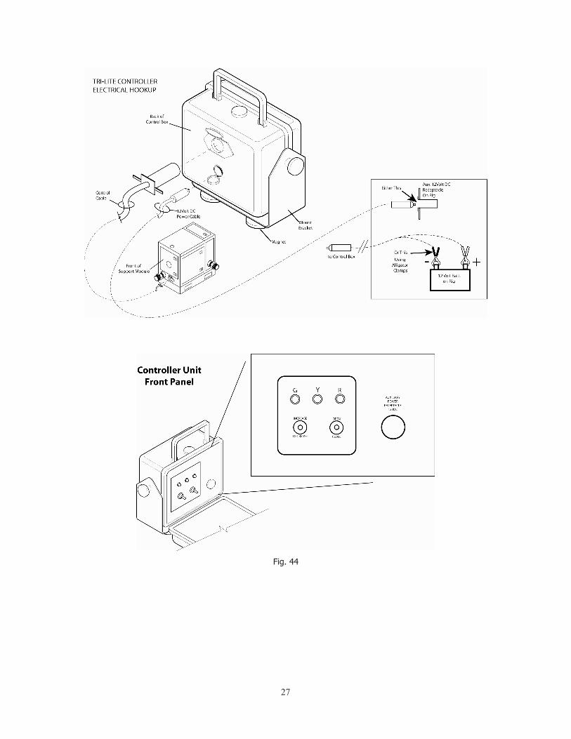
7c. Tri-Light Valve Controller The Tri-Light controller is stored in a compartment in the top of the support pack (Fig 43). Open the compartment door and remove the controller by its handle. Also, remove the control cable and power cord which are stored in the same compartment.
7b. Whip Check at Air Outlet to Support Pack Using the same procedure as in step 7a, install two whip checks and 2” x 30’ air hose to the air outlet fitting of the support pack and to drill rig. Tighten air hoses with a hammer. Remove slack and tighten whip checks (see Fig. 42).

26
Fig. 43
The controller housing is equipped with an adjustable pivoting mounting bracket. Attached to the bracket are magnets that allow for convenient placement of controller on the drill rig adjacent to the operator.
There are two cables to hook up for the Tri-Lite controller. The control cable connects to the rear of the control housing (see Fig. 44) and runs to the front of the support pack. The 12 volt DC power cord runs from the back of the control housing, to the auxiliary power jack (if available) on the drill rig. WARNING Electrical Shock and Burning Hazard Connection of the clamps to the wrong battery post will result in burning of the wires. User will experience possible electrical shock and burns to the skin. The alligator clamps must be connected properly.
NOTICE Equipment Damage Connection of the clamps to the wrong battery post will result in burning of the wires and possibly the controller unit. Alligator clamps must be connected correctly.
If there is no power jack on the rig, then an alternate power cord is supplied which has alligator clamps on the supply end in order to connect directly to the drill rig 12v DC battery. Alligator clamps must be connected correctly: Red (positive) clamp to positive (+) post on the battery; Black (negative) clamp to negative (-) post on the battery. (see Fig 44)
27
Fig. 44

28
7d. Fluid Pump Setup and Maintenance Adequate lubrication oil level must be maintained for proper operation of the CAT pump. The manufacturer recommends using CAT PUMP OIL, or SAE 10W30 hydraulic oil with anti-wear and rust inhibitors. Oil is added to a level that is even with the red dot in the middle of the sight glass located on the rear cover of the crankcase housing (see Fig. 45 & 46).
Fig. 45
Fig. 46

29
7e. Oil Properties and Tank Filling Rock Drill Oil Properties To prevent the wearing of internal parts, corrosion and part failure, the air hammer must have a constant and adequate supply of rock drill oil. (see Oil Properties, Fig. 47). Exxon AROX EP series, and Chevron VISTAC series (or equivalent grade) are the recommended brands for use in the air hammer. Your local lubricant representative will recommend the proper grade for use in your specific drilling environment. NOTICE Equipment Damage Never use hydraulic oil, engine oil, gear oil or diesel for lubricating the air hammer. Doing so may result in equipment damage.
Fig. 47

30
With air compressor installed and running and air supply valve at the drill rig fully open, toggle the “Increase-Decrease” switch on the Tri-Light controller to run the hammer at half the air flow for a few minutes. This allows the oil to flow through the air supply lines, drill stem and air hammer thus lubricating internal components. The correct consumption of oil is dependent upon the air volume and conditions. See lubrication graph below for recommendations (see Fig. 48).
NOTE: when drilling in wet conditions, the normal amount of oil should be doubled. Also, there should be obvious visual evidence of oil around the drill bit shank, and within the pipe joints when changing drill stem.
Chart: Air Volume to OilFig. 48
The recommended grade of oil is dependent on the ambient temperature in which drilling is taking place, as well as the operating pressure. The oil properties chart will aid in selecting the proper viscosity of oil for a given ambient temperature range.

31
Tank Filling
When filling the oil tank with rock drill oil, always follow this procedure: WARNING Contents under pressure To avoid possible injury, shut off the compressor and close its outlet valve before performing this setup.
a) Turn off the Tri-Lite controller Valves at the support pack. Indicators on the valves will be pointing perpendicular to the valve bodies and the air in/air out lines. WARNING Contents under pressure - Eye protection required Keep away from exhaust end of vent valve. Open vent valve slowly. Exposure to air escaping under pressure may result in serious eye and other bodily injury. b) Open the air vent valve on top of the oil tank, releasing air pressure inside the tank to atmospheric pressure.
c) When oil tank is fully vented, use a hammer to loosen the tangs on the 4 inch oil tank cap, then unscrew and remove the cap by hand.(see Fig. 49).
Fig. 49

32
d) With cap removed, fill oil tank with appropriate rock drill oil (see Fig. 47). The level of oil in the tank must not be higher than one inch from the top of the stand pipe.
The oil tank is full when there is oil up to the 3/4 mark on the sight glass.
e) Install the tank cap. Tighten with hammer by striking the tangs on the tank cap ring.
WARNING Fluids escaping under pressure Escapingfluidsmaybesprayedintosupportpack.Closevent valve before starting compressor. f) Close the vent valve on top of the tank. This valve must be closed before starting the compressor, otherwise the tank contents will be sprayed into the inside of the support pack.
Check List This completes the initial equipment setup before starting the Air Compressor. It is important to conduct a quick system check prior to starting the compressor, as follows:
1. Air supply hose (2 inch) to drill rig is connected, from air outlet at support pack, to connection at drill rig. Insure that whip checks are correctly installed.
2. Air supply hose (2 inch) to support pack inlet, from air compressor outlet is connected and whip checks are installed.
3. Verify that all four air supply hose ends have been tightened using a hammer.
4. Verify that the oil tank cap on the support module has been tightened using a hammer.
5. Oil tank vent valve is in “Closed” or “Off” position (handle turned perpendicular to the valve body). (See Fig. 51 & 52).

33
Oil Tank Vent Valve Fig. 50
6. Power connections (12 volts DC at the drill rig) for Tri-Lite Valve controller have been made (see Fig. 44).
7. Check for proper electrical function of the solenoid controlled air inlet and air outlet valves by toggling the switch on the Tri-Light controller from “Open” to “Closed”. When air inlet and outlet valves are “Open” the green light should be illuminated on the Tri-Light controller. When the toggle switch is in the “Closed” position, the red light should be illuminated on the Tri-Light controller. When the valves are in a position other than fully open or fully closed, the yellow light will be illuminated.
NOTE: there is an arrow indicator on top of the air inlet valve which shows whether the valve is Open (arrow in line with the valve) or Closed (arrow perpendicular with the valve body).
8. Before starting the compressor, the electrically controlled air inlet and air outlet valves on the support pack must be “Closed”. Also, the manual air inlet valve (where the air supply hose from the support pack connects) at the drill rig must be “Closed”.
-INITIAL SYSTEM SETUP IS COMPLETE-
Fig. 51

34
8. SETUP OF SUPPORT PACK/ AIR PRESSURE APPLIED
8a. Setup of Air Compressor - adjustments prior to drilling operations Set up the air compressor at the work site following manufacturers instructions. air compressor, support pack and drill rig should be arranged so that the supplied air supply hoses will reach to all three units.
The air compressor used should be capable of maintaining a minimum of 400 cfm and 200 psi output (see Fig. 52).
Fig. 52
Start the air compressor
Open the compressor outlet valve slowly so that air pressure is supplied to the support pack.
8b. Pressure Regulator Setup and Adjustment Set the pressure regulator on the support pack to 80psi (Fig 53 & 54). To set the pressure, insure that the air inlet valve at the drill rig is “Closed”, then , using the Tri-Light controller, open the air inlet and air outlet valves on the support pack (toggle switch to “OPEN” – green light comes on). This will cause the system to become pressurized. Rotate the pressure regulator knob until a reading of 80 psi is displayed on the pressure gauge. Following adjustment, turn Tri-Light controller to “CLOSE” (red light).

35
Fig. 53
8c. Oiler Adjustment The needle valve (located under the air tank on support module) controls the amount of oil being introduced into the air supplied to the air hammer. For an initial adjustment, turn the needle valve completely off (turn clockwise until it stops). Then turn the valve adjustment three full turns counterclockwise (see Fig. 55).
Fig. 55
Fig. 54

36
There are two valves located on the lines running out the bottom of the oil tank. One controls the air “IN” to the tank; the other controls the oil “OUT” of the tank. These valves are how the oiler is turned on and off. They should be fully open (handles parallel with the valves) during drilling and fully closed (handles perpendicular to the valves) when not drilling (see Fig 56).
Fig. 56

37
8d. Water Pump Adjustment and Operation The support pack is mounted on a skid which contains a water tank. For the water pump to operate correctly it is important that the supply line from the water tank is always full of water during start-up and operation so that the pump will stay “primed”.
There is a water shut-off valve and quick disconnect fitting in the inlet water line from water tank to water pump. This is where the water tank can be drained for servicing.
During initial start-up, insure that the water tank is full, and always maintained at a level higher than the inlet supply line to the pump. Insure that the inlet line is connected, shut-off valve is fully open and the line is full of water (no air pockets). If there is an air pocket visible in the inlet water line then “bleed” the line by shutting off the valve, disconnecting the line, then cracking the valve open enough to purge the air from the line. Then reconnect the line and re-open the valve (fully) so that the inlet side of the water pump will be primed with water.
IMPORTANT: •Bentonite should not be run through the water pump. Polymer is acceptable if clay formations are anticipated. •Check the in-line filter (on the inlet side of the pump) periodically, for debris.
NOTICE Equipment Damage Equipment damage may occur if the water freezes. When not drilling, drain all water if there is a potential for freezing conditions. •When not operating the drill and there is the potential for freezing conditions, drain water from the water tank and inlet lines of the pump, then anti-freeze the pump (see Fig. 58).
Fig. 57

38
The water pump is driven by an air motor that is coupled to the input shaft of
the water pump. A ball valve (water flow rate) on the line to the air motor controls the RPM of the water pump and the resulting amount of water (gpm) being introduced into the drilling operation. With the valve fully opened, the maximum amount of 5 gpm will be pumped. A “clean bore” is obtained depending on drilling conditions. Approximately 1/2 to 4 gallons per minute can produce good results, however soft rock may require more water and hard rock may require less water. Begin a new bore with the water flow rate valve set to half open, until drilling conditions can be determined, then adjust the valve setting for more or less water (while drilling) as the situation dictates (see Fig. 58 & 59).
Fig. 59
Fig. 58

39
9. AIR HAMMER OPERATION
9a. Setting Up: Dig a spoils pit. Typically a spoils pit is dug 10 to 15 feet in front of the drill to allow a place for the spoils to exhaust into (see Fig. 60).
Fig 60
9b. Attaching the Down Hole assembly: Position the first joint of drill pipe through the drill pipe guide on your drill rig. Fully coat the pin thread of the drill pipe adapter with no-gall thread grease, then thread on the fully assembled down hole assembly.
WARNING Rotating Parts Never use rig power or other powered equipment when making up or breaking out threaded connections.
Serious injury or death may result from rotating parts or from thrown wrenches.
Tighten to hand-tight, then use the StraightLine (or equivalent) breakout wrench kit to tighten the down hole assembly to the drill string.
Removal of the down hole assembly is conducted in the same way. 9c. Setup for Operation: 1) For best results, enter the ground at the shallowest possible entry angle.
2) If the rock formation is at or near the surface, dig an entrance pit with the face perpendicular to the drill bit to facilitate getting the hole started. 3) If the rock formation is deep or in front of the drill rig, as is common

40
with creek crossings, drill to the rock formation with your standard dirt head. When you reach the rock formation, retract the drill string, attach the down hole assembly and rotate back to the rock formation. Begin drilling as outlined in 9d., below.
9d. Thrust Pressure for Drilling and Steering: The appropriate amount of thrust force for both the drilling and steering operations is just enough to create the required resistance to set the hammer into motion. Applying too much thrust pressure will not achieve faster penetration rates. It will actually cause an adverse effect, it will not allow the hammer to beat at an optimal rate, will slow production and cause premature wear on the bit. The correct thrust rate can be heard and felt by the operator. When the correct thrust pressure is being applied, there is very little vibration felt by the operator. When applied correctly, there is a bass tone to the hammer and a very light harmonic vibration felt by the operator. The sound that the hammer makes when being used correctly is unmistakable.
When the hammer is being pushed too hard or crowded, there is a noticeable difference in the sound and feel. The sound will become high pitched and “pinging”, much like striking a hammer lightly on tin. There is also a very noticeable increase in vibration at the operator’s station.
The hammer has almost no sound or feedback to the operator when not being pushed enough. The hammer requires positive pressure against the bit face in order to operate. There will be times in softer ground conditions when this occurs.
9e. Steering the StraightLine Air Hammer: In order to steer upward (toward 12 o’clock) with the hammer, use the rigs thrust control to engage the face of the bit with the rock formation; maintain between 300 - 600 pounds of thrust. The percussive action of the piston will begin. Rotate the face of the bit, carving between 9 o’clock and 3 o’clock (180 degrees). It is recommended to mark the drill stem at the desired clock positions as a reference point. Note: you must maintain a constant thrust pressure to prevent the loss of percussive action in the hammer. It isn’t necessary to back the bit away from engagement to rotate in a counter clockwise direction, as long as the rotation is less than a full turn. Follow the above instructions to steer in any desired direction by simply changing your clock positions. Continue carving the rock face until you achieve 2% slope change, then rotate the hammer one full revolution. This carving action creates a keyhole shape; the one full revolution adds clearance for the hammer’s rear steering point and prevents binding the tool in the bore hole (see Fig. 61 & 62). Failure to perform this rotation can allow the assembly to become lodged in the bore hole.

41
Fig 62
9f. Maintaining a clean round hole: Once the bore has progressed 30 feet you must swab the hole. This is accomplished by maintaining normal drilling rotation between 25 to 40 rpm and retracting and advancing the drill string the length of the drill pipe. This process will help keep the hole clean and should be done at the completion of every joint of drill pipe for the duration of the bore.
9g. Drilling Straight: Once the desired depth, pitch and direction have been obtained and you want to drill straight, you rotate the drill string between 25 and 35 rpm while maintaining 300-600 pounds of force against the bit face. Swabbing the hole is necessary during this process as well as it will assist in maintaining a clean round bore hole.
Fig. 61

42
9h. Cleaning and Storage after each use: WARNING Rotating Parts Never use rig power or other powered equipment when making up or breaking out threaded connections.
Serious injury or death may result from rotating parts or from thrown wrenches.
1) Upon completion of a bore operation, remove the air hammer from the drill string using the StraightLine (or equivalent) breakout wrench kit.
2) Remove the adapter from the back of the transmitter housing, then, using retrieval tool, remove the transmitter.
3) Power wash the entire air hammer tool.
4) Pour rock drill oil into the rear (transmitter end) of the air hammer so that it coats all internal components down through the bit end.

43
4445
4647
4849
5051
5253
5455
5657
58
IV APPENDIX
1. Transmitter Assembly: Exploded Parts Breakdown................................. Transmitter Assembly: BOM................................................................
2. Air Hammer Assembly: Exploded Parts Breakdown................................. Air Hammer Assembly: BOM................................................................
3. Support Pack Frame and Shrouds: Exploded PartsBreakdown.................. Support Pack Frame and Shrouds:BOM.................................................
4. Support Pack Oiler System: Exploded PartsBreakdown............................ Support Pack Oiler System: BOM..........................................................
5. Support Pack Water System: Exploded PartsBreakdown......................... Support Pack Water System: BOM........................................................
6. Support Pack Air System: ExplodedPartsBreakdown ............................. Support Pack Air System: BOM.............................................................
7. Support Pack Decals............................................................................ Support Pack Decals : BOM..................................................................
8. Tool Kit with Breakout Wrench Kit.........................................................

44
TRANSMITTER AND ADAPTEREXPLODED PARTS

45
TRANSMITTER AND ADAPTERBOM

46
HAMMER, BIT & BENT SUBEXPLODED PARTS

47
HAMMER, BIT & BENT SUBBOM

48
SUPPORT PACK FRAME & SHROUDSEXPLODED PARTS

49
SUPPORT PACK FRAME & SHROUDSBOM

50
SUPPORT PACK OILER SYSTEMEXPLODED PARTS

51
SUPPORT PACK OILER SYSTEMBOM

52
SUPPORT PACK WATER SYSTEMEXPLODED PARTS

53
SUPPORT PACK WATER SYSTEMBOM

54
SUPPORT PACK AIR SYSTEMEXPLODED PARTS

55
SUPPORT PACK AIR SYSTEMBOM

56
SUPPORT PACK DECALSEXPLODED PARTS

57
SUPPORT PACK DECALSBOM

58

59
Finco, Inc.1816 E. Wasp Rd.Hutchinson, KS 67501
Tele: 620-802-0200www.straightlinehdd.com
Parts & Operations Manual
AIR HAMMERMODEL 4.0 & 5.0