TABLE OF CONTENTS - Panasonic · DS-DG-9320-MB-ETU REV. 1.1 SUBJECT Development Kit PAN9320 PAN9320...
25
CLASSIFICATION Reference & Design Guide No. DS-DG-9320-MB-ETU REV. 1.1 SUBJECT Development Kit PAN9320 PAN9320 Mother board and PAN9320/10-ETU PAGE 1 of 25 CUSTOMER’S CODE PAN9320-KIT & PAN9320/10-ETU PANASONIC’S CODE PAN9320-MB & PAN9320/10-ETU DATE 16.12.2015 PAN9320 Reference & Design Guide
Transcript of TABLE OF CONTENTS - Panasonic · DS-DG-9320-MB-ETU REV. 1.1 SUBJECT Development Kit PAN9320 PAN9320...
CLASSIFICATION Reference & Design Guide No. DS-DG-9320-MB-ETU
REV. 1.1
SUBJECT Development Kit PAN9320
PAN9320 Mother board and PAN9320/10-ETU PAGE
1 of 25
CUSTOMER’S CODE PAN9320-KIT & PAN9320/10-ETU
PANASONIC’S CODE PAN9320-MB & PAN9320/10-ETU
DATE
16.12.2015
PAN9320 Reference & Design Guide
CLASSIFICATION Reference & Design Guide No. DS-DG-9320-MB-ETU
REV. 1.1
SUBJECT Development Kit PAN9320
PAN9320 Mother board and PAN9320/10-ETU PAGE
2 of 25
CUSTOMER’S CODE PAN9320-KIT & PAN9320/10-ETU
PANASONIC’S CODE PAN9320-MB & PAN9320/10-ETU
DATE
16.12.2015
TABLE OF CONTENTS
1. Scope of this Document ................................................................................................ 3
2. Ordering Information ..................................................................................................... 3
3. History for this Document .............................................................................................. 3
4. Related Documents ....................................................................................................... 3
5. PAN9320 Key benefits .................................................................................................. 4
6. Wireless Local Area Network Overview ......................................................................... 4
7. Description of the PAN9320 .......................................................................................... 5
8. Block Diagram PAN9320 ............................................................................................... 5
9. PAN9320-ETU (Easy-to-use) Daughter Board .............................................................. 6
9.1. Functionality ......................................................................................................... 6
9.2. Schematic ............................................................................................................ 7
9.3. Placement Drawing .............................................................................................. 8
10. PAN9320-MB Mother Board .......................................................................................... 9
10.1. Functionality ......................................................................................................... 9
10.2. Schematic .......................................................................................................... 10
10.3. Placement Drawing ............................................................................................ 11
11. PAN9320 PCB Layout ................................................................................................. 12
11.1. Footprint Dimension and Pin-Out ....................................................................... 12
11.2. Layout Recommendation ................................................................................... 13
12. PAN9320-ETU Daughter Board Layout ....................................................................... 14
12.1. PAN9320-ETU PCB Pattern ............................................................................... 14
12.2. PAN9320-ETU / PAN9310-ETU PCB Stack-Up ................................................. 18
12.3. PAN9310-ETU 50 Ohm Impedance Simulation .................................................. 18
12.4. PAN9310-ETU 50 Ohm Trace ............................................................................ 19
12.5. Chip-Antenna Reference Design ........................................................................ 20
12.5.1. Schematic ............................................................................................. 20
12.5.2. Antenna and Trace Layout .................................................................... 20
12.5.3. PCB Layout 4-Layer .............................................................................. 21
13. PAN9320 Development Kit (PAN9320-MB & PAN9320-ETU) ..................................... 22
14. PAN9320 Ready To Use Communication Service ....................................................... 23
15. PAN9320 Command Interface ..................................................................................... 24
16. General Information ..................................................................................................... 25
17. FCC Warning .............................................................................................................. 25
18. Life Support Policy ...................................................................................................... 25
CLASSIFICATION Reference & Design Guide No. DS-DG-9320-MB-ETU
REV. 1.1
SUBJECT Development Kit PAN9320
PAN9320 Mother board and PAN9320/10-ETU PAGE
3 of 25
CUSTOMER’S CODE PAN9320-KIT & PAN9320/10-ETU
PANASONIC’S CODE PAN9320-MB & PAN9320/10-ETU
DATE
16.12.2015
1. SCOPE OF THIS DOCUMENT
This Reference and Design Guide covers the PAN9320/10-ETU (Easy-To-Use) and PAN9320-MB (Mother board) and its Development Kit. The goal of this document is to allow and guide users to easily and promptly integrate the PAN9320 and PAN9310 into end-products.
This guide describes the hardware and system concepts and gives useful usage and integration guidance. Software related documents are mentioned in the Quick Start Guide
[3] and Communication Specification
[4].
2. ORDERING INFORMATION
Ordering P/N KIT Name Hardware
Module on ETU Description MB ETU
ENW49A01AYEF PAN9320-KIT V2 V2.1 ENW49A01A3EF PAN9320 Development Kit with one PAN9320-MB and one PAN9320-ETU including two HS USB cable
ENW49A01AZEF PAN9320-ETU - V2.1 ENW49A01A3EF PAN9320-ETU Daughter board with PAN9320 module (incl. Chip-ANT)
ENW49A01CZEF PAN9310-ETU - V2.1 ENW49A01C3EF PAN9310-ETU Daughter board with PAN9310 module and SMA connector
3. HISTORY FOR THIS DOCUMENT
Revision Date Modification / Remarks
1.0 26.11.2015 Initial Release
1.1 16.12.2015 12.5.1 Schematic – Correction of C1
4. RELATED DOCUMENTS
[1] PAN9320 Datasheet PAN9320 Download Page (Datasheet)
[2] PAN9320 Flyer PAN9320 Download Page (Flyer)
[3] PAN9320 Quick Start Guide PAN9320 Download Page (Quick Start Guide)
[4] PAN9320 Comm Specification PAN9320 Download Page (Communication Specification)
[5] PAN9320 Application Note PAN9320 Download Page (Application Note)
CLASSIFICATION Reference & Design Guide No. DS-DG-9320-MB-ETU
REV. 1.1
SUBJECT Development Kit PAN9320
PAN9320 Mother board and PAN9320/10-ETU PAGE
4 of 25
CUSTOMER’S CODE PAN9320-KIT & PAN9320/10-ETU
PANASONIC’S CODE PAN9320-MB & PAN9320/10-ETU
DATE
16.12.2015
5. PAN9320 KEY BENEFITS
Surface Mount Type (SMT) measured 29.0 x 13.5 x 2.66 [mm]³
Wireless Local Area Network (WLAN) module with integrated MCU and Radio
Operating in the 2.4GHz ISM band
Supports the following IEEE 802.11 standards: IEEE 802.11b/g payload data rates IEEE 802.11n high throughput data rates IEEE 802.11i security: WEP, and WPA/WPA2 (TKIP, AES-CCMP) IEEE 802.11e Quality of Service (QoS)
TX power up to +18dBm (IEEE 802.11b)
Outstanding Rx sensitivity -98dBm (IEEE 802.11b DSSS 1Mbps) -75dBm (IEEE 802.11g OFDM 54Mbps) -73dBm (IEEE 802.11n MCS7 HT20 65Mbps) -70dBm (IEEE 802.11n MCS7 HT40 135Mbps)
Coexistence interface for external co-located 2.4GHz radios (e.g. Bluetooth)
Internal crystal oscillators for Radio (40MHz) and MCU (32MHz) inside
Integrated memory for customer web contents and configuration file (1MByte)
Memory extension with an external QSPI flash (2MByte) is optional
Two UART interfaces (command and binary data)
Integrated shielding to resist EMI
Available with either integrated antenna (PAN9320) or dedicated RF pad for external antennas (PAN9310)
6. WIRELESS LOCAL AREA NETWORK OVERVIEW
A Wireless Local Area Network (WLAN) is a medium range, wireless network based on the IEEE 802.11 standard, and uses the ubiquities ISM (Industrial, Scientific and Medical) frequency range of 2,4GHz. The 802.11 standard pertains to the first two layers of the OSI model, and covers Physical Layer (PHY), the Data Link Layer (DLL) with its two sub-layers: Logical Link Control (LLC), and Media Access Control (MAC). WLAN networks utilize two operating modes to connect stations (STAs) equipped with a wireless network adapter. The first is known as the Infrastructure Mode where the wireless STAs are connected via one or more access points (APs). An AP is a device that allows STAs to connect with each other or to a wired network. The second is the Ad-hoc mode, where wireless STAs are connected without any access point.
WLAN devices typically have a high transmit power, of 15 to 20 dBm, allowing them to reach a range of up to 100 meters. Furthermore, WLAN devices are commonly used to transmit high throughput data such as Audio or Video streaming using Orthogonal Frequency Division Multiplexing (OFDM) modulation. The Carrier Sense Multiple Access with Collosion Avoidance (CSMA/CA) mechanism enables the parallel access of more than one device to the wireless medium of a IEEE 802.11 network. The following security mechanisms are deployed: 1. Adavanced Encryption Standard (AES) with Counter Mode CBC-MAC Protocol (CCMP), 2. Cipher-Based Message Authentication Code (CMAC) and 3. Wired Equivalent Privacy (WEP) with Temporal Key Integrity Protocol (TKIP). Video, voice and multimedia applications are supported by the IEEE 802.11e Quality of Service amendment.
CLASSIFICATION Reference & Design Guide No. DS-DG-9320-MB-ETU
REV. 1.1
SUBJECT Development Kit PAN9320
PAN9320 Mother board and PAN9320/10-ETU PAGE
5 of 25
CUSTOMER’S CODE PAN9320-KIT & PAN9320/10-ETU
PANASONIC’S CODE PAN9320-MB & PAN9320/10-ETU
DATE
16.12.2015
7. DESCRIPTION OF THE PAN9320
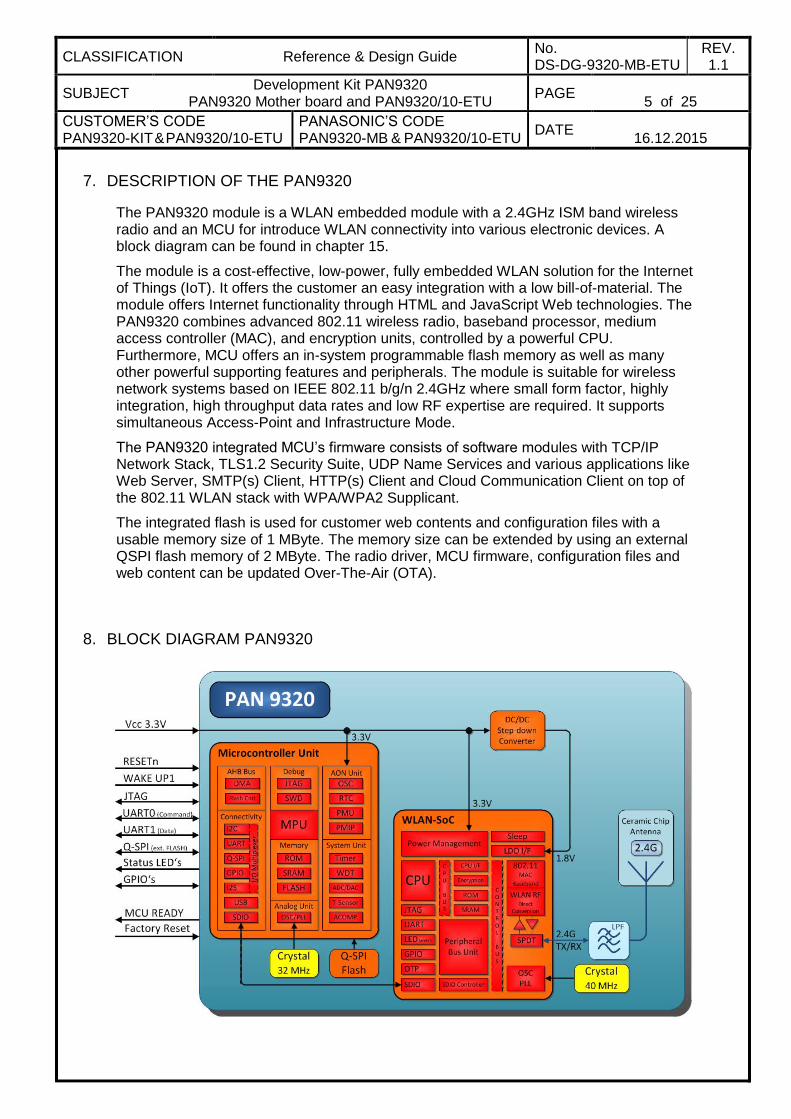
The PAN9320 module is a WLAN embedded module with a 2.4GHz ISM band wireless radio and an MCU for introduce WLAN connectivity into various electronic devices. A block diagram can be found in chapter 15.
The module is a cost-effective, low-power, fully embedded WLAN solution for the Internet of Things (IoT). It offers the customer an easy integration with a low bill-of-material. The module offers Internet functionality through HTML and JavaScript Web technologies. The PAN9320 combines advanced 802.11 wireless radio, baseband processor, medium access controller (MAC), and encryption units, controlled by a powerful CPU. Furthermore, MCU offers an in-system programmable flash memory as well as many other powerful supporting features and peripherals. The module is suitable for wireless network systems based on IEEE 802.11 b/g/n 2.4GHz where small form factor, highly integration, high throughput data rates and low RF expertise are required. It supports simultaneous Access-Point and Infrastructure Mode.
The PAN9320 integrated MCU’s firmware consists of software modules with TCP/IP Network Stack, TLS1.2 Security Suite, UDP Name Services and various applications like Web Server, SMTP(s) Client, HTTP(s) Client and Cloud Communication Client on top of the 802.11 WLAN stack with WPA/WPA2 Supplicant.
The integrated flash is used for customer web contents and configuration files with a usable memory size of 1 MByte. The memory size can be extended by using an external QSPI flash memory of 2 MByte. The radio driver, MCU firmware, configuration files and web content can be updated Over-The-Air (OTA).
8. BLOCK DIAGRAM PAN9320
CLASSIFICATION Reference & Design Guide No. DS-DG-9320-MB-ETU
REV. 1.1
SUBJECT Development Kit PAN9320
PAN9320 Mother board and PAN9320/10-ETU PAGE
6 of 25
CUSTOMER’S CODE PAN9320-KIT & PAN9320/10-ETU
PANASONIC’S CODE PAN9320-MB & PAN9320/10-ETU
DATE
16.12.2015
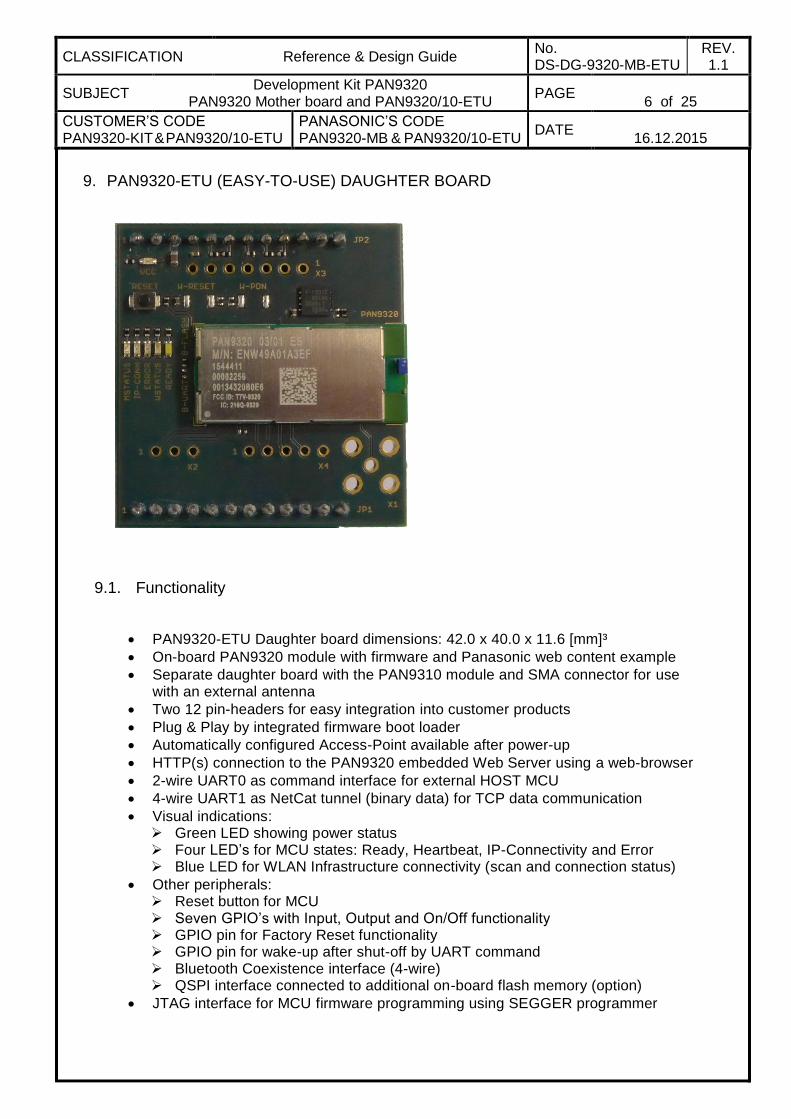
9. PAN9320-ETU (EASY-TO-USE) DAUGHTER BOARD
9.1. Functionality
PAN9320-ETU Daughter board dimensions: 42.0 x 40.0 x 11.6 [mm]³
On-board PAN9320 module with firmware and Panasonic web content example
Separate daughter board with the PAN9310 module and SMA connector for use with an external antenna
Two 12 pin-headers for easy integration into customer products
Plug & Play by integrated firmware boot loader
Automatically configured Access-Point available after power-up
HTTP(s) connection to the PAN9320 embedded Web Server using a web-browser
2-wire UART0 as command interface for external HOST MCU
4-wire UART1 as NetCat tunnel (binary data) for TCP data communication
Visual indications: Green LED showing power status Four LED’s for MCU states: Ready, Heartbeat, IP-Connectivity and Error Blue LED for WLAN Infrastructure connectivity (scan and connection status)
Other peripherals: Reset button for MCU Seven GPIO’s with Input, Output and On/Off functionality GPIO pin for Factory Reset functionality GPIO pin for wake-up after shut-off by UART command Bluetooth Coexistence interface (4-wire) QSPI interface connected to additional on-board flash memory (option)
JTAG interface for MCU firmware programming using SEGGER programmer
CLASSIFICATION Reference & Design Guide No. DS-DG-9320-MB-ETU
REV. 1.1
SUBJECT Development Kit PAN9320
PAN9320 Mother board and PAN9320/10-ETU PAGE
7 of 25
CUSTOMER’S CODE PAN9320-KIT & PAN9320/10-ETU
PANASONIC’S CODE PAN9320-MB & PAN9320/10-ETU
DATE
16.12.2015
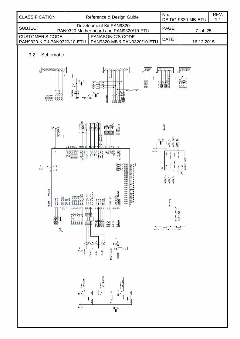
9.2. Schematic
CLASSIFICATION Reference & Design Guide No. DS-DG-9320-MB-ETU
REV. 1.1
SUBJECT Development Kit PAN9320
PAN9320 Mother board and PAN9320/10-ETU PAGE
8 of 25
CUSTOMER’S CODE PAN9320-KIT & PAN9320/10-ETU
PANASONIC’S CODE PAN9320-MB & PAN9320/10-ETU
DATE
16.12.2015
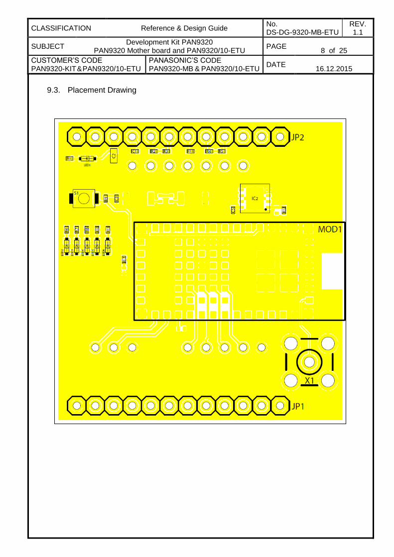
9.3. Placement Drawing
CLASSIFICATION Reference & Design Guide No. DS-DG-9320-MB-ETU
REV. 1.1
SUBJECT Development Kit PAN9320
PAN9320 Mother board and PAN9320/10-ETU PAGE
9 of 25
CUSTOMER’S CODE PAN9320-KIT & PAN9320/10-ETU
PANASONIC’S CODE PAN9320-MB & PAN9320/10-ETU
DATE
16.12.2015
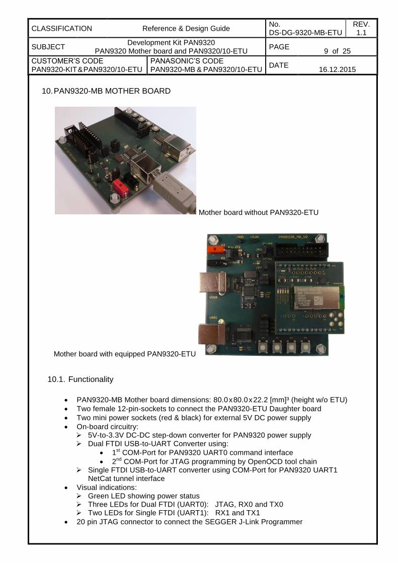
10. PAN9320-MB MOTHER BOARD
Mother board without PAN9320-ETU
Mother board with equipped PAN9320-ETU
10.1. Functionality
PAN9320-MB Mother board dimensions: 80.0 x 80.0 x 22.2 [mm]³ (height w/o ETU)
Two female 12-pin-sockets to connect the PAN9320-ETU Daughter board
Two mini power sockets (red & black) for external 5V DC power supply
On-board circuitry: 5V-to-3.3V DC-DC step-down converter for PAN9320 power supply Dual FTDI USB-to-UART Converter using:
1st COM-Port for PAN9320 UART0 command interface
2nd COM-Port for JTAG programming by OpenOCD tool chain Single FTDI USB-to-UART converter using COM-Port for PAN9320 UART1
NetCat tunnel interface
Visual indications: Green LED showing power status Three LEDs for Dual FTDI (UART0): JTAG, RX0 and TX0 Two LEDs for Single FTDI (UART1): RX1 and TX1
20 pin JTAG connector to connect the SEGGER J-Link Programmer
CLASSIFICATION Reference & Design Guide No. DS-DG-9320-MB-ETU
REV. 1.1
SUBJECT Development Kit PAN9320
PAN9320 Mother board and PAN9320/10-ETU PAGE
10 of 25
CUSTOMER’S CODE PAN9320-KIT & PAN9320/10-ETU
PANASONIC’S CODE PAN9320-MB & PAN9320/10-ETU
DATE
16.12.2015
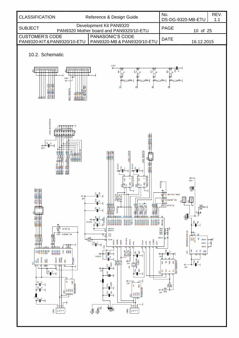
10.2. Schematic
CLASSIFICATION Reference & Design Guide No. DS-DG-9320-MB-ETU
REV. 1.1
SUBJECT Development Kit PAN9320
PAN9320 Mother board and PAN9320/10-ETU PAGE
11 of 25
CUSTOMER’S CODE PAN9320-KIT & PAN9320/10-ETU
PANASONIC’S CODE PAN9320-MB & PAN9320/10-ETU
DATE
16.12.2015
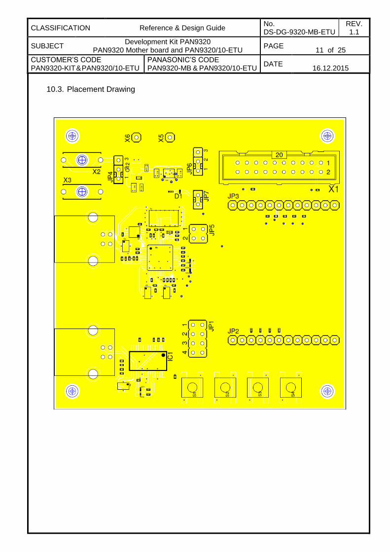
10.3. Placement Drawing
CLASSIFICATION Reference & Design Guide No. DS-DG-9320-MB-ETU
REV. 1.1
SUBJECT Development Kit PAN9320
PAN9320 Mother board and PAN9320/10-ETU PAGE
12 of 25
CUSTOMER’S CODE PAN9320-KIT & PAN9320/10-ETU
PANASONIC’S CODE PAN9320-MB & PAN9320/10-ETU
DATE
16.12.2015
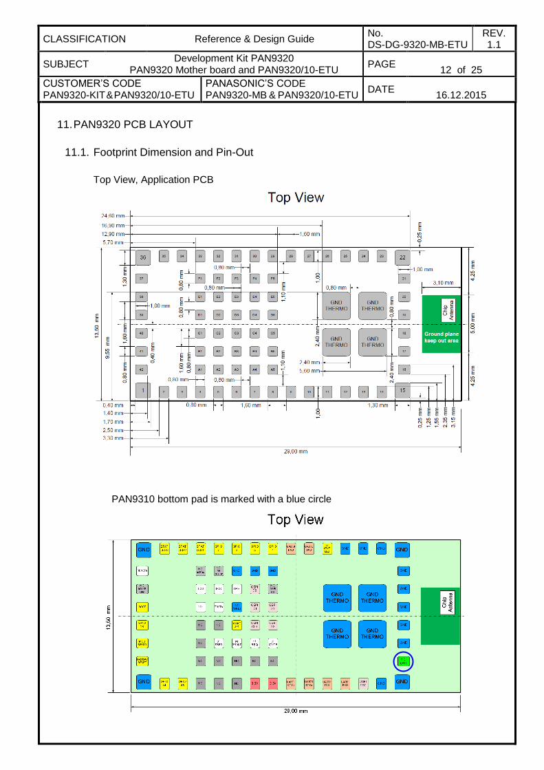
11. PAN9320 PCB LAYOUT
11.1. Footprint Dimension and Pin-Out
Top View, Application PCB
PAN9310 bottom pad is marked with a blue circle
CLASSIFICATION Reference & Design Guide No. DS-DG-9320-MB-ETU
REV. 1.1
SUBJECT Development Kit PAN9320
PAN9320 Mother board and PAN9320/10-ETU PAGE
13 of 25
CUSTOMER’S CODE PAN9320-KIT & PAN9320/10-ETU
PANASONIC’S CODE PAN9320-MB & PAN9320/10-ETU
DATE
16.12.2015
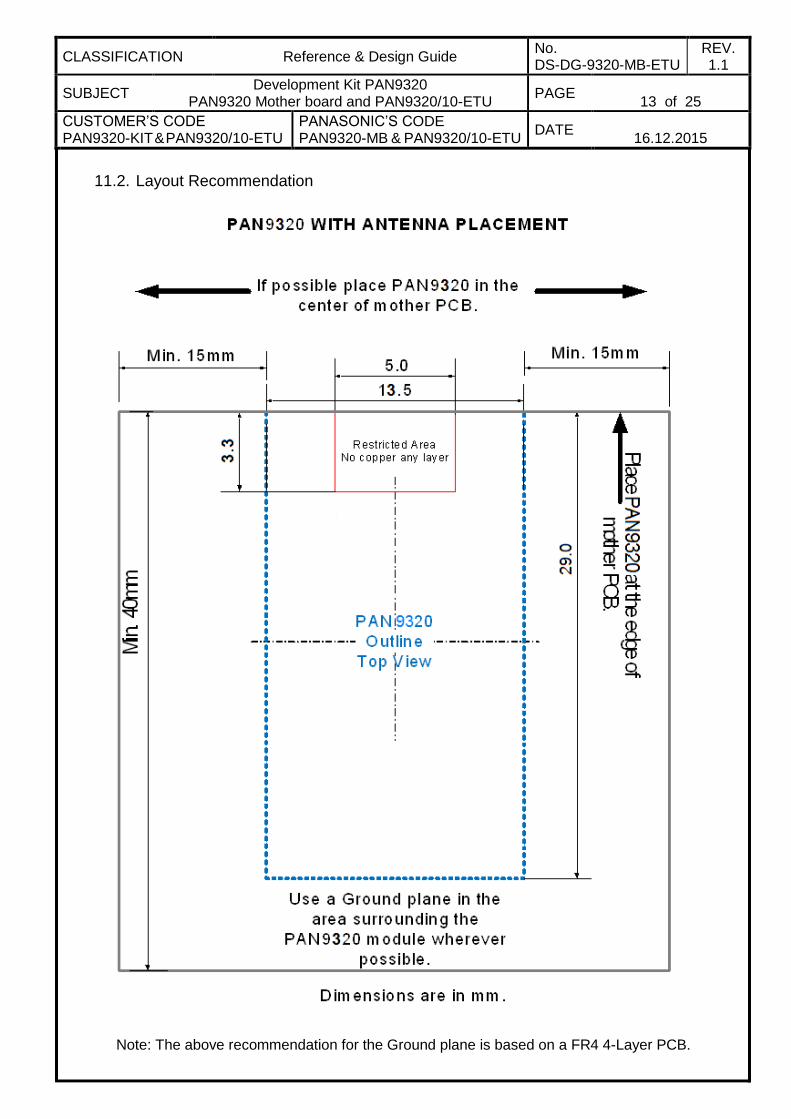
11.2. Layout Recommendation
Note: The above recommendation for the Ground plane is based on a FR4 4-Layer PCB.
CLASSIFICATION Reference & Design Guide No. DS-DG-9320-MB-ETU
REV. 1.1
SUBJECT Development Kit PAN9320
PAN9320 Mother board and PAN9320/10-ETU PAGE
14 of 25
CUSTOMER’S CODE PAN9320-KIT & PAN9320/10-ETU
PANASONIC’S CODE PAN9320-MB & PAN9320/10-ETU
DATE
16.12.2015
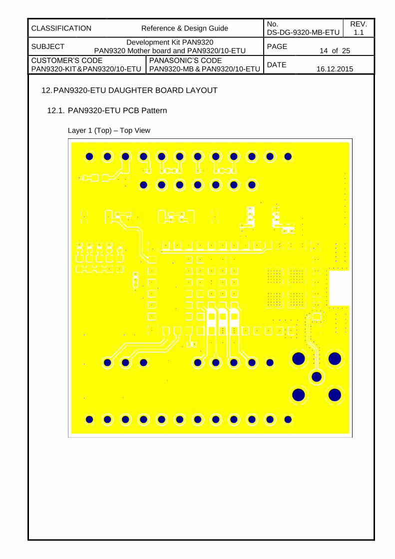
12. PAN9320-ETU DAUGHTER BOARD LAYOUT
12.1. PAN9320-ETU PCB Pattern
Layer 1 (Top) – Top View
CLASSIFICATION Reference & Design Guide No. DS-DG-9320-MB-ETU
REV. 1.1
SUBJECT Development Kit PAN9320
PAN9320 Mother board and PAN9320/10-ETU PAGE
15 of 25
CUSTOMER’S CODE PAN9320-KIT & PAN9320/10-ETU
PANASONIC’S CODE PAN9320-MB & PAN9320/10-ETU
DATE
16.12.2015
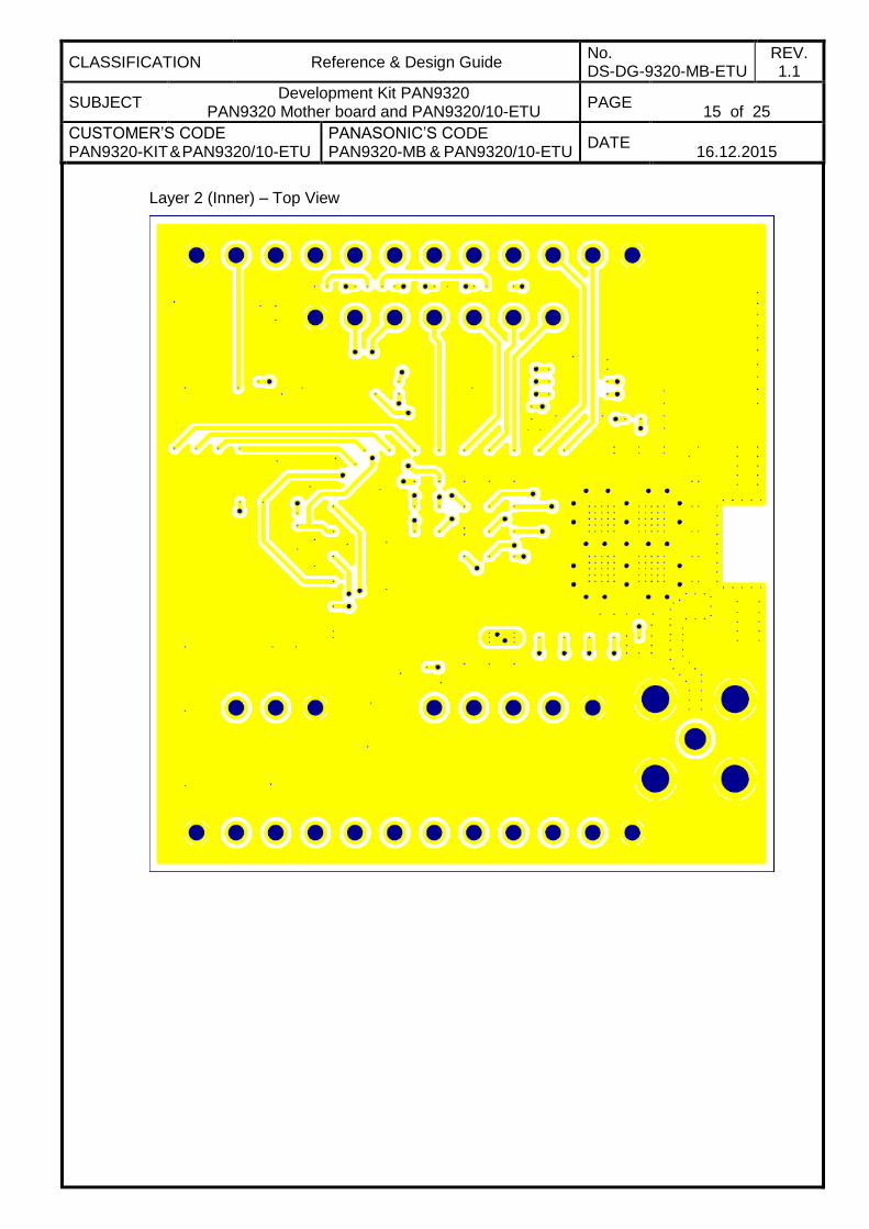
Layer 2 (Inner) – Top View
CLASSIFICATION Reference & Design Guide No. DS-DG-9320-MB-ETU
REV. 1.1
SUBJECT Development Kit PAN9320
PAN9320 Mother board and PAN9320/10-ETU PAGE
16 of 25
CUSTOMER’S CODE PAN9320-KIT & PAN9320/10-ETU
PANASONIC’S CODE PAN9320-MB & PAN9320/10-ETU
DATE
16.12.2015
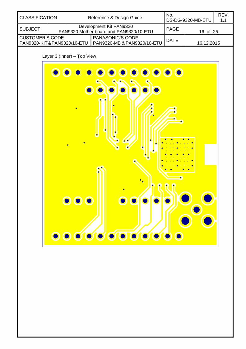
Layer 3 (Inner) – Top View
CLASSIFICATION Reference & Design Guide No. DS-DG-9320-MB-ETU
REV. 1.1
SUBJECT Development Kit PAN9320
PAN9320 Mother board and PAN9320/10-ETU PAGE
17 of 25
CUSTOMER’S CODE PAN9320-KIT & PAN9320/10-ETU
PANASONIC’S CODE PAN9320-MB & PAN9320/10-ETU
DATE
16.12.2015
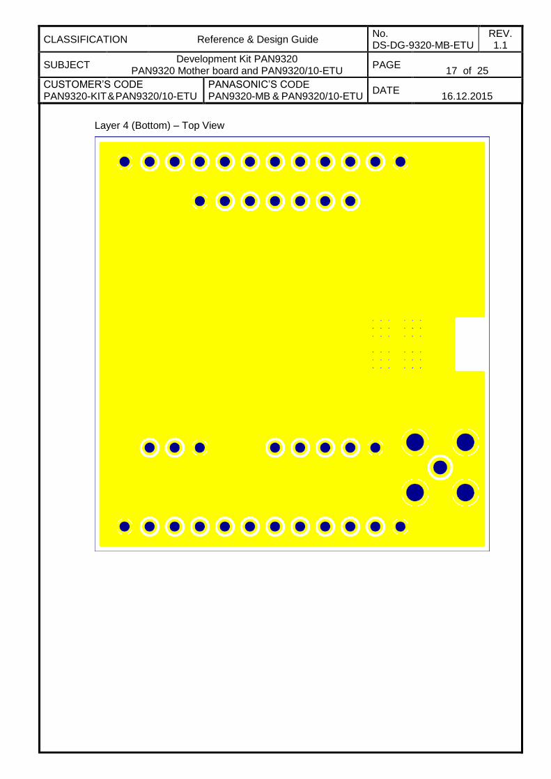
Layer 4 (Bottom) – Top View
CLASSIFICATION Reference & Design Guide No. DS-DG-9320-MB-ETU
REV. 1.1
SUBJECT Development Kit PAN9320
PAN9320 Mother board and PAN9320/10-ETU PAGE
18 of 25
CUSTOMER’S CODE PAN9320-KIT & PAN9320/10-ETU
PANASONIC’S CODE PAN9320-MB & PAN9320/10-ETU
DATE
16.12.2015
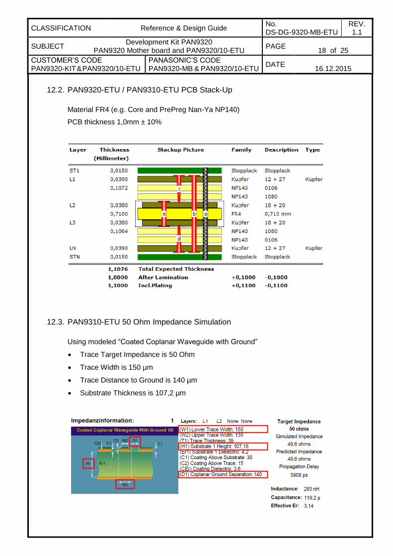
12.2. PAN9320-ETU / PAN9310-ETU PCB Stack-Up
Material FR4 (e.g. Core and PrePreg Nan-Ya NP140)
PCB thickness 1,0mm ± 10%
12.3. PAN9310-ETU 50 Ohm Impedance Simulation
Using modeled “Coated Coplanar Waveguide with Ground”
Trace Target Impedance is 50 Ohm
Trace Width is 150 µm
Trace Distance to Ground is 140 µm
Substrate Thickness is 107,2 µm
CLASSIFICATION Reference & Design Guide No. DS-DG-9320-MB-ETU
REV. 1.1
SUBJECT Development Kit PAN9320
PAN9320 Mother board and PAN9320/10-ETU PAGE
19 of 25
CUSTOMER’S CODE PAN9320-KIT & PAN9320/10-ETU
PANASONIC’S CODE PAN9320-MB & PAN9320/10-ETU
DATE
16.12.2015
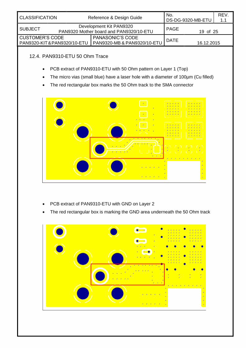
12.4. PAN9310-ETU 50 Ohm Trace
PCB extract of PAN9310-ETU with 50 Ohm pattern on Layer 1 (Top)
The micro vias (small blue) have a laser hole with a diameter of 100µm (Cu filled)
The red rectangular box marks the 50 Ohm track to the SMA connector
PCB extract of PAN9310-ETU with GND on Layer 2
The red rectangular box is marking the GND area underneath the 50 Ohm track
CLASSIFICATION Reference & Design Guide No. DS-DG-9320-MB-ETU
REV. 1.1
SUBJECT Development Kit PAN9320
PAN9320 Mother board and PAN9320/10-ETU PAGE
20 of 25
CUSTOMER’S CODE PAN9320-KIT & PAN9320/10-ETU
PANASONIC’S CODE PAN9320-MB & PAN9320/10-ETU
DATE
16.12.2015
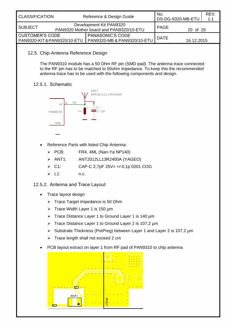
12.5. Chip-Antenna Reference Design
The PAN9310 module has a 50 Ohm RF pin (SMD pad). The antenna trace connected to the RF pin has to be matched to 50ohm impedance. To keep this the recommended antenna trace has to be used with the following components and design.
12.5.1. Schematic
Reference Parts with listed Chip Antenna:
PCB: FR4, 4ML (Nan-Ya NP140)
ANT1: ANT2012LL13R2400A (YAGEO)
C1: CAP-C 2,7pF 25V= +/-0,1p 0201 COG
L1: n.c.
12.5.2. Antenna and Trace Layout
Trace layout design
Trace Target Impedance is 50 Ohm
Trace Width Layer 1 is 150 µm
Trace Distance Layer 1 to Ground Layer 1 is 140 µm
Trace Distance Layer 1 to Ground Layer 2 is 107,2 µm
Substrate Thickness (PrePreg) between Layer 1 and Layer 2 is 107,2 µm
Trace length shall not exceed 2 cm
PCB layout extract on layer 1 from RF pad of PAN9310 to chip antenna
CLASSIFICATION Reference & Design Guide No. DS-DG-9320-MB-ETU
REV. 1.1
SUBJECT Development Kit PAN9320
PAN9320 Mother board and PAN9320/10-ETU PAGE
21 of 25
CUSTOMER’S CODE PAN9320-KIT & PAN9320/10-ETU
PANASONIC’S CODE PAN9320-MB & PAN9320/10-ETU
DATE
16.12.2015
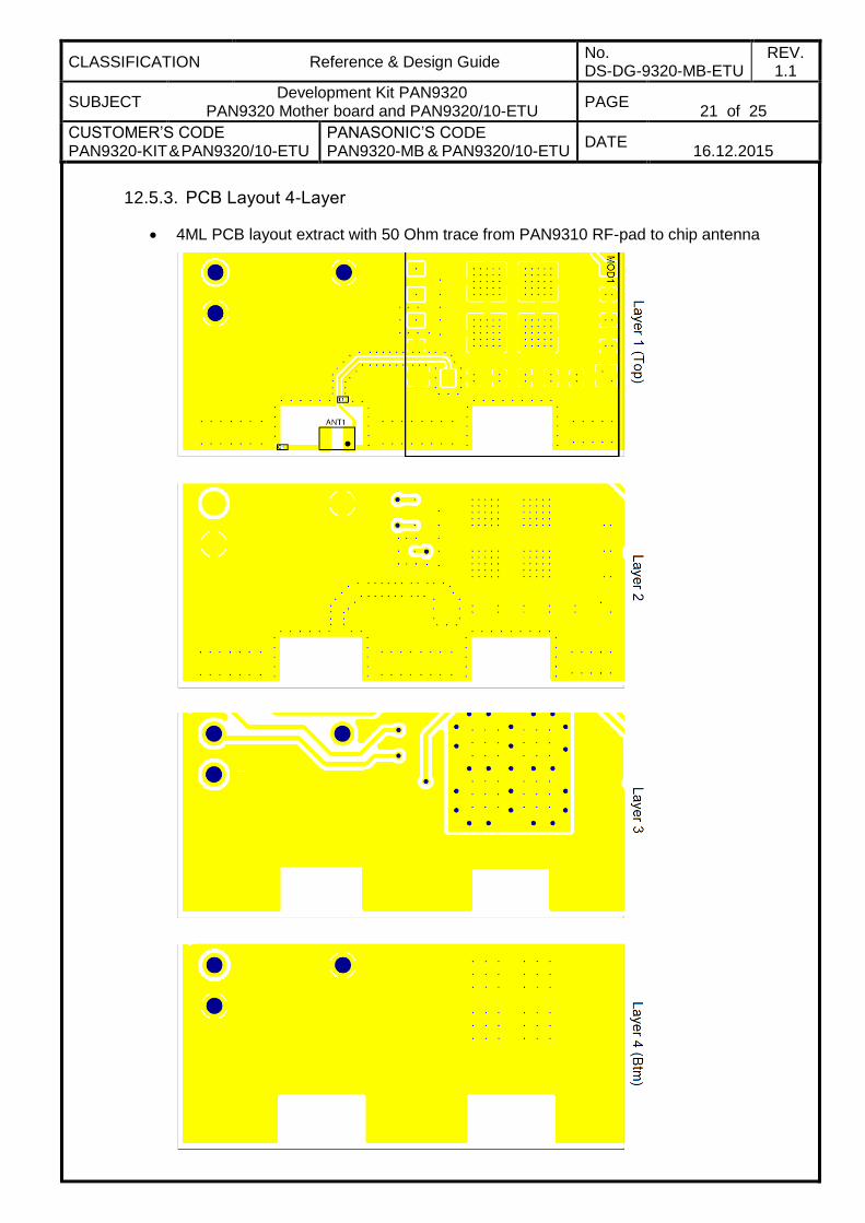
12.5.3. PCB Layout 4-Layer
4ML PCB layout extract with 50 Ohm trace from PAN9310 RF-pad to chip antenna
CLASSIFICATION Reference & Design Guide No. DS-DG-9320-MB-ETU
REV. 1.1
SUBJECT Development Kit PAN9320
PAN9320 Mother board and PAN9320/10-ETU PAGE
22 of 25
CUSTOMER’S CODE PAN9320-KIT & PAN9320/10-ETU
PANASONIC’S CODE PAN9320-MB & PAN9320/10-ETU
DATE
16.12.2015
13. PAN9320 DEVELOPMENT KIT (PAN9320-MB & PAN9320-ETU)
The PAN9320 Development Kit includes:
1 pc. Panasonic Carrying Case
1 pc. PAN9320-MB Mother board
1 pc. PAN9320-ETU Daughter board
1 pc. High-Speed USB Cable
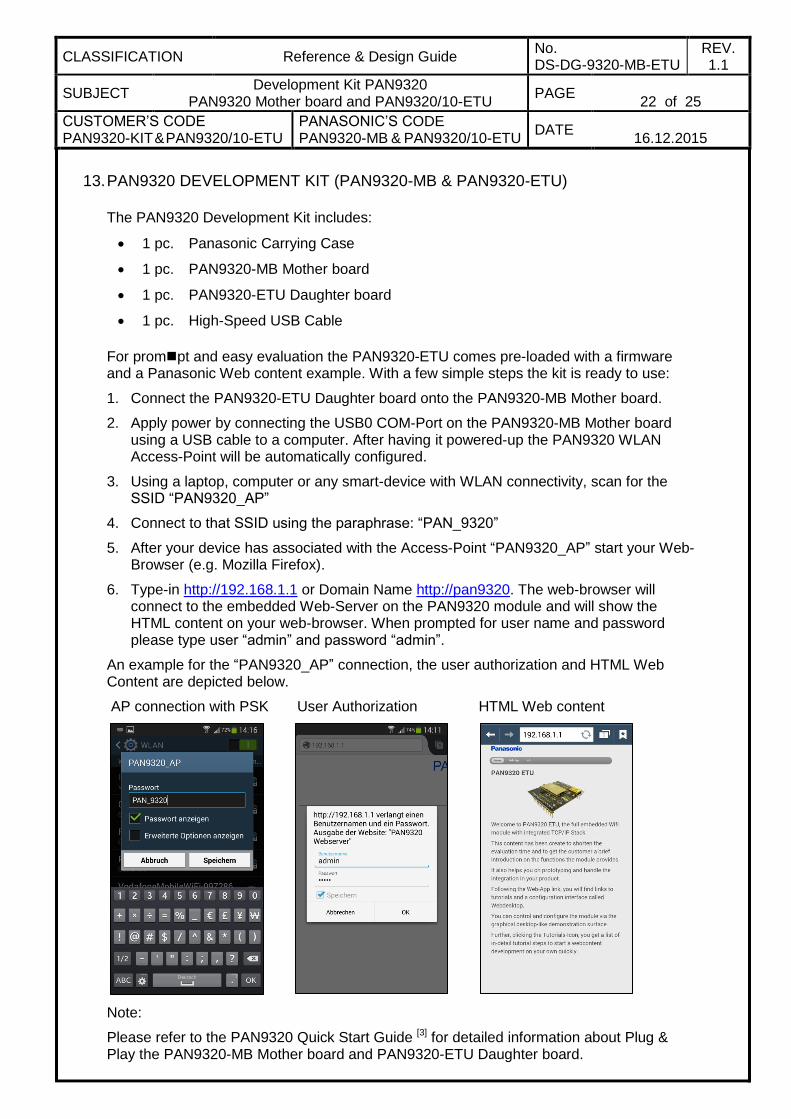
For prompt and easy evaluation the PAN9320-ETU comes pre-loaded with a firmware and a Panasonic Web content example. With a few simple steps the kit is ready to use:
1. Connect the PAN9320-ETU Daughter board onto the PAN9320-MB Mother board.
2. Apply power by connecting the USB0 COM-Port on the PAN9320-MB Mother board using a USB cable to a computer. After having it powered-up the PAN9320 WLAN Access-Point will be automatically configured.
3. Using a laptop, computer or any smart-device with WLAN connectivity, scan for the SSID “PAN9320_AP”
4. Connect to that SSID using the paraphrase: “PAN_9320”
5. After your device has associated with the Access-Point “PAN9320_AP” start your Web-Browser (e.g. Mozilla Firefox).
6. Type-in http://192.168.1.1 or Domain Name http://pan9320. The web-browser will connect to the embedded Web-Server on the PAN9320 module and will show the HTML content on your web-browser. When prompted for user name and password please type user “admin” and password “admin”.
An example for the “PAN9320_AP” connection, the user authorization and HTML Web Content are depicted below.
AP connection with PSK User Authorization HTML Web content
Note:
Please refer to the PAN9320 Quick Start Guide [3] for detailed information about Plug & Play the PAN9320-MB Mother board and PAN9320-ETU Daughter board.
CLASSIFICATION Reference & Design Guide No. DS-DG-9320-MB-ETU
REV. 1.1
SUBJECT Development Kit PAN9320
PAN9320 Mother board and PAN9320/10-ETU PAGE
23 of 25
CUSTOMER’S CODE PAN9320-KIT & PAN9320/10-ETU
PANASONIC’S CODE PAN9320-MB & PAN9320/10-ETU
DATE
16.12.2015
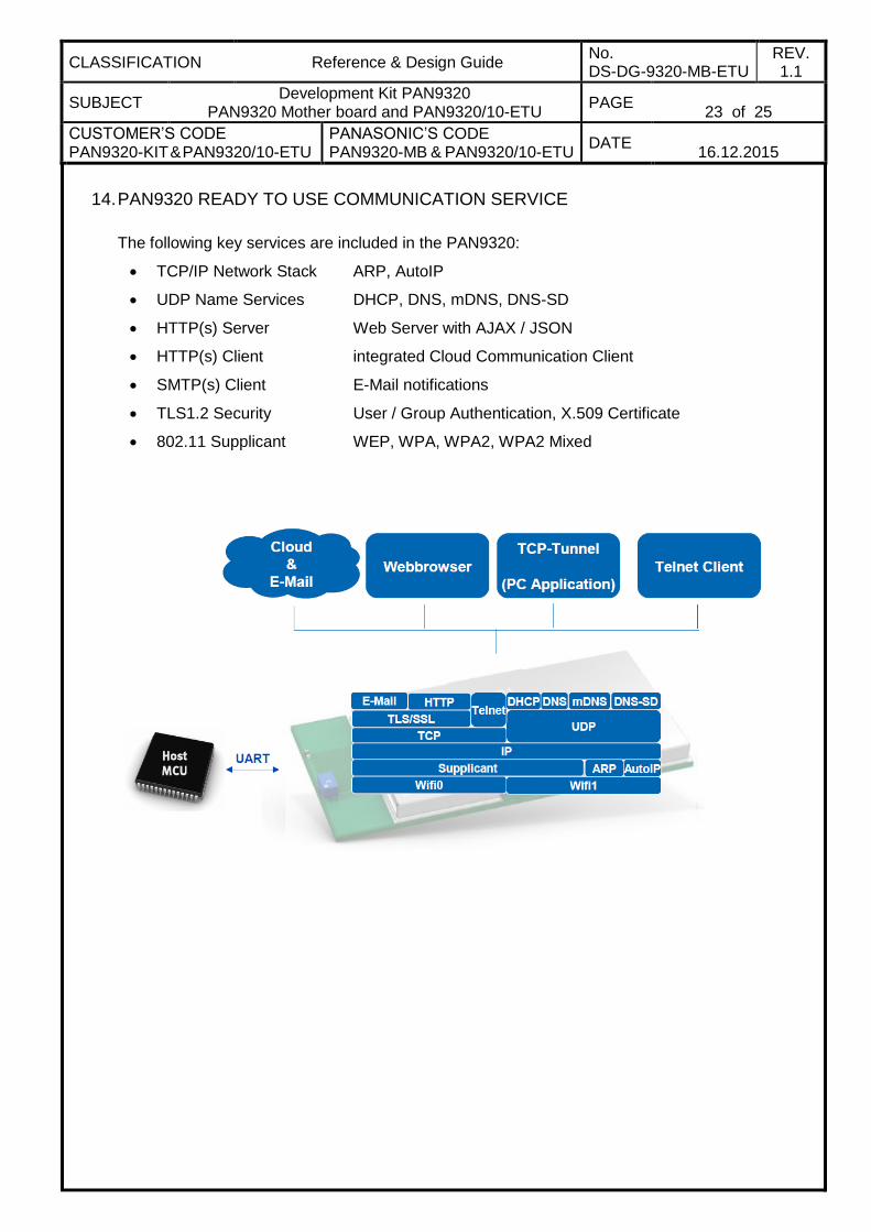
14. PAN9320 READY TO USE COMMUNICATION SERVICE
The following key services are included in the PAN9320:
TCP/IP Network Stack ARP, AutoIP
UDP Name Services DHCP, DNS, mDNS, DNS-SD
HTTP(s) Server Web Server with AJAX / JSON
HTTP(s) Client integrated Cloud Communication Client
SMTP(s) Client E-Mail notifications
TLS1.2 Security User / Group Authentication, X.509 Certificate
802.11 Supplicant WEP, WPA, WPA2, WPA2 Mixed
CLASSIFICATION Reference & Design Guide No. DS-DG-9320-MB-ETU
REV. 1.1
SUBJECT Development Kit PAN9320
PAN9320 Mother board and PAN9320/10-ETU PAGE
24 of 25
CUSTOMER’S CODE PAN9320-KIT & PAN9320/10-ETU
PANASONIC’S CODE PAN9320-MB & PAN9320/10-ETU
DATE
16.12.2015
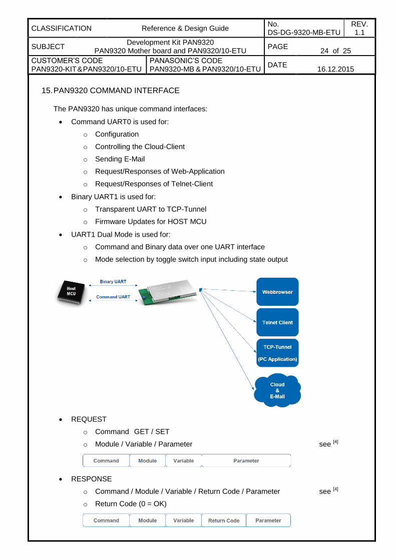
15. PAN9320 COMMAND INTERFACE
The PAN9320 has unique command interfaces:
Command UART0 is used for:
o Configuration
o Controlling the Cloud-Client
o Sending E-Mail
o Request/Responses of Web-Application
o Request/Responses of Telnet-Client
Binary UART1 is used for:
o Transparent UART to TCP-Tunnel
o Firmware Updates for HOST MCU
UART1 Dual Mode is used for:
o Command and Binary data over one UART interface
o Mode selection by toggle switch input including state output
REQUEST
o Command GET / SET
o Module / Variable / Parameter see [4]
RESPONSE
o Command / Module / Variable / Return Code / Parameter see [4]
o Return Code (0 = OK)

CLASSIFICATION Reference & Design Guide No. DS-DG-9320-MB-ETU
REV. 1.1
SUBJECT Development Kit PAN9320
PAN9320 Mother board and PAN9320/10-ETU PAGE
25 of 25
CUSTOMER’S CODE PAN9320-KIT & PAN9320/10-ETU
PANASONIC’S CODE PAN9320-MB & PAN9320/10-ETU
DATE
16.12.2015
16. GENERAL INFORMATION
© Panasonic Industrial Devices Europe GmbH 2015.
All rights reserved.
Panasonic does not warranty and accepts no liability for the information contained herein. The information contained in this document is subject to change without notice. Modules containing “ES” in the series number are Engineering Samples -- i.e. PANxxxx ES. This means, the design of this product is not yet concluded. Engineering Samples may be partially or fully functional, and there may be differences to be published Data Sheet.
Engineering Samples are not qualified and are not to be used for reliability testing or series production.
Disclaimer:
Customer acknowledges that samples may deviate from the Data Sheet and may bear defects due to their status of development and the lack of qualification mentioned above.
Panasonic rejects any liability or product warranty for Engineering Samples. In particular, Panasonic disclaims liability for damages caused by
the use of the Engineering Sample other than for Evaluation Purposes, particularly the installation or integration in another product to be sold by Customer,
deviation or lapse in function of Engineering Sample,
improper use of Engineering Samples.
Panasonic disclaimes any liability for consequential and incidental damages.
In case of any questions, please contact your local sales partner or the related product manager.
17. FCC WARNING
This equipment is intended for use in a laboratory test environment only. It generates, uses, and can radiate radio frequency energy and has not been tested for compliance with the limits of computing devices pursuant to subpart J of part 15 of FCC rules, which are designed to provide reasonable protection against radio frequency interference. Operation of this equipment in other environments may cause interference with radio communications, in which case the user at his own expense will be required to take whatever measures may be required to correct this interference.
The FCC and other regulatory certifications for the PAN9320 will be published in the PAN9320 Datasheet [1].
18. LIFE SUPPORT POLICY
This Panasonic product is not designed for use in life support appliances, devices, or systems where malfunction can reasonably be expected to result in a significant personal injury to the user, or as a critical component in any life support device or system whose failure to perform can be reasonably expected to cause the failure of the life support device or system, or to affect its safety or effectiveness. Panasonic customers using or selling these products for use in such applications do so at their own risk and agree to fully indemnify Panasonic Industrial Devices Europe GmbH for any damages resulting.