Table of Contents - TOPDON of Contents 1.Safety Precautions and Warnings 2.General Information 2.1...
24
Transcript of Table of Contents - TOPDON of Contents 1.Safety Precautions and Warnings 2.General Information 2.1...


Table of Contents1. Safety Precautions and Warnings
2. General Information2.1 On-Board Diagnostics(OBDII)2.2 Diagnostic Trouble Codes ( DTCs ) 2.3 Location of the Data Link Connector(DLC) 2.4 OBDII Readiness Monitors 2.5 OBDII Monitor Readiness Status 2.6 OBDII Definitions
3.Using the Scan Tool3.1 Tool Description-ArtLink201 3.2 Specifications 3.3 Package List 3.4 Setup 3.5 Read Test 3.6 About
4.OBDII/EOBD Diagnostics4.1 Read Codes 4.2 Erase Codes 4.3 I/M Readiness 4.4 Data Stream 4.5 Freeze Frame 4.6 O2 Sensor Test/On-Board Monitoring/Evap System Test 4.7 Vehicle Information
5 Update
6.Warranty and Service6.1 Limited One Year Warranty 6.2 Service Procedures
01
02
02
0304
0506
07
0808
09
10
10
11
12
12
13
14
15
16
17
18
18
19
20
20
20
02

1.Safety Precautions and Warnings
2. General Information
2.1 On-Board Diagnostics(OBDII)
To prevent personal injury or damage to vehicles and/or the scan tool, please read this user’s manual first carefully and observe the following safety precautions at a minimum whenever working on a vehicle: Always perform automotive testing in a safe environment. Do not attempt to operate or observe the tool while driving a vehicle. Operating or observing the tool will cause driver distraction and could cause a fatal accident. Wear safety eye protection that meets ANSI standards. Keep clothing, hair, hands, tools, test equipment, etc. away from all moving or hot engine parts. Operate the vehicle in a well-ventilated work area: Exhausted gases are poisonous. Put blocks in front of the drive wheels and never leave the vehicle unattended while running tests. Use extreme caution when working around the ignition coil, distributor cap, ignition wires and spark plugs. These components create hazardous voltages when the engine is running. Put the transmission in P (for A/T) or N (for M/T) and make sure the parking brake is engaged.
Keep a fire extinguisher suitable for gasoline/chemical/ electrical fires nearby. Don’t connect or disconnect any test equipment while the ignition is on or the engine is running. Keep this tool dry, clean, free from oil/water or grease. Use a mild detergent or a clean cloth to clean it if necessary.
The first generation of On-Board Diagnostics (called OBDI) was developed by the California Air Resources Board (ARB)
02

2.2 Diagnostic Trouble Codes (DTCs)
and implemented in 1988 to monitor some of the emission control components on vehicles. As technology evolved and the desire to improve the On-Board Diagnostic system increased, a new generation of On-Board Diagnostic system was developed. This second generation of On-Board Diagnostic regulations is called “OBDII”. The OBDII system is designed to monitor emission control systems and key engine components by performing either continuous or periodic tests of specific components and vehicle conditions. When a problem is detected, the OBDII system turns on a warning lamp (MIL) on the vehicle instrument panel to alert the driver typically by the phrase of “Check Engine” or “Service Engine Soon”. The system will also store important information about the detected malfunction so that a technician can accurately find and fix the problem. Here below follow three pieces of such valuable information:1 ) Whether the Malfunction Indicator Light (MIL) is commanded ‘ON’ or ‘OFF’;2 ) Which, if any, Diagnostic Trouble Codes (DTCs) are stored;3 ) Readiness Monitor status.
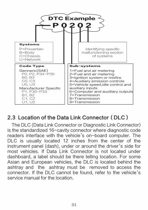
OBDII Diagnostic Trouble Codes are codes that are stored by the on-board computer diagnostic system in response to a problem found in the vehicle. These codes identify a particular problem area and are intended to provide you with a guide as to where a fault might be occurring within a vehicle. OBDII Diagnostic Trouble Codes consist of a five-digit alphanumeric code. The first character, a letter, identifies which control system sets the code. The second character, a number, 0-3; other three characters, a hex character, 0-9 or A-F provide additional information on where the DTC originated and the operating conditions that caused it to set. Here below is an example to illustrate the structure of the digits:
03
2.3 Location of the Data Link Connector(DLC)
The DLC (Data Link Connector or Diagnostic Link Connector) is the standardized 16-cavity connector where diagnostic code readers interface with the vehicle’s on-board computer. The DLC is usually located 12 inches from the center of the instrument panel (dash), under or around the driver’s side for most vehicles. If Data Link Connector is not located under dashboard, a label should be there telling location. For some Asian and European vehicles, the DLC is located behind the ashtray and the ashtray must be removed to access the connector. If the DLC cannot be found, refer to the vehicle’s service manual for the location.
DTC Example
P 0 2 0 2
Systoms
P=PowertainB=BodyC=ChassisU=Network
Identifying specificmaifunctioning section
of systems
Code Type
Genneric(SAE)P0, P2, P34-P39B0, B3C0, C3U0, U3
Manufacturer SpecificP1, P30-P33B1, B2C1, C2U1, U2
Sub-systems
1=Fuel and air metering2=Fuel and air metering3=Ignition system or misfire4=Auxiliary emission controls5=Vehicle speed,idle control.andauxiliary inputs6=Computer and auxiliary outputs7=Transmission8=Transmission9=Transmission
04

2.4 OBDII Readiness Monitors
An important part of a vehicle’s OBDII system is the Readiness Monitors, which are indicators used to find out if all of the emissions components have been evaluated by the OBDII system. They are running periodic tests on specific system and components to ensure that they are performing within allowable limits. Currently, there are eleven OBDII Readiness Monitors (or I/M Monitors) defined by the U.S. Environmental Protection Agency(EPA). Not all monitors are supported by all vehicles and the exact number of monitors in any vehicle depends on the motor vehicle manufacturer’s emissions control strategy. Continuous Monitors-Some of the vehicle components or systems are continuously tested by the vehicle’s OBDII system, while others are tested only under specific vehicle operating conditions. The continuously monitored components listed below are always ready:1 ) Misfire2 ) Fuel System3 ) Comprehensive Components(CCM)
05

Once the vehicle is running, the OBDII system is continuously checking the above components, monitoring key engine sensors, watching for engine misfire, and monitoring fuel demands. Non-Continuous Monitors-Unlike the continuous monitors, many emissions and engine system components require the vehicle to be operated under specific conditions before the monitor is ready. These monitors are termed non-continuous monitors are listed below:1. EGR System-Exhaust Gas Recirculation for reducinggreenhouse gases.2. O2 Sensors-Monitor and adjust air/fuel mixture.3. Catalyst-Reduces exhaust emissions.4. Evaporative System-Monitors the integrity of the fuel tanksystem.5. O2 Sensor Heater-Brings O2 sensor to correct operatingtemperature.6. Secondary air-Reduces exhaust emissions.7. Heated Catalyst-Brings Catalyst to correct operatingtemperature.8. A/C system-Monitors system for Freon leaks.
OBDII system must indicate whether or not the vehicle’s PCM’s monitoring has completed testing on each emission component. Components that have been OBDII tested will be reported as “OK”. The purpose of recording readiness status is to allow inspectors to determine if the vehicle’s OBDII system has tested all the emissions systems. This is handy to know before bringing vehicle to a state emissions testing facility. Powertrain Control Module sets a monitor to a “OK” after an appropriate drive cycle has been performed. The drive cycle that enables a Monitor and sets readiness codes to “OK” varies for each individual monitor. Once a
2.5 OBDII Monitor Readiness Status
06

monitor is set as “OK”, it will remain in this state. A number of factors, including erasing of diagnostic trouble codes (DTCs) with a code reader or a disconnected battery, can result in Readiness Monitors being set to “INC”(incomplete). Since the three continuous monitor are constantly evaluating, they will be reported as “OK” all of the time. As long as there are no DTCs stored in memory, the vehicle is running in accordance with the OBDII guidelines. If testing of a particular supports non-continuous monitor has not been completed or not tested, the monitor status will be reported as “INC” (incomplete). In order for the OBD monitor system to become ready, the vehicle should be driven under a variety of normal operating conditions. These operating conditions may include a mix of highway driving and stop and go, city type driving, and at least one overnight-off period. For specific information on getting your vehicle’s OBD monitor system ready, please consult your vehicle owner’s manual.
Powertrain Control Module -The OBDII terminology for the on-board computer that controls the engine and drive train. Malfunction Indicator Light (MIL)-Malfunction Indicator Light (Service Engine Soon, Check Engine) is a term used for the light on the instrument panel. It is to alert the driver and/or the repair technician that there is a problem with one or more of vehicle’s systems and may cause emissions to exceed federal standards. If the MIL illuminates with a steady light, it indicates that a problem has been detected and the vehicle should be serviced as soon as possible. Under certain conditions, the dashboard light will blink or flash. This indicates a severe problem and flashing is intended to discourage vehicle operation. The vehicle onboard diagnostic system cannot turn the MIL off until necessary repairs are completed or the
2.6 OBDII Definitions
07

condition no longer exists. DTCs-Diagnostic Trouble Codes (DTCs) these indentify which section of the emission control system has malfunctioned. Enabling Criteria-Also termed Enabling Conditions. They are the vehicle-specific events of conditions that must occur within are engine before the various monitors will set, or run. Some monitors require the vehicle to follow a prescribed “drive cycle” routine as part of the enabling criteria. Drive cycles vary among vehicles and for each monitor in any particular vehicle. OBDII Drive Cycle-A specific mode of vehicles operation that offers conditions required to set all the readiness monitors application to the vehicle to the “ready” condition. The purpose of completing an OBDII drive cycle is to force the vehicle to run its onboard diagnostics. Some form of a drive cycle needs to be performed after DTCs have been erased from the PCM memory or after the battery has been disconnected. Running through a vehicle’s complete drive cycle will “set” the readiness monitors so that future faults can be detected. Drive cycles vary depending on the vehicle and monitor that needs to be reset. For vehicle specific drive cycle, consult the vehicle’s Owner’s Manual. Freeze Frame Data-When an emissions related fault occurs, the OBDII system not only sets a code, but also records a snapshot of the vehicle operating parameters to help in identifying the problem. This set of values operating parameters to help in identifying the problem. This set of values is referred to as Freeze Frame Data and may include important engine parameters such as engine RPM, vehicle speed, air flow, engine load, fuel pressure, fuel trim value, engine coolant temperature, ignition timing advance, or closed loop status.
08
3. Using the Scan Tool3.1 Tool Description-ArtLink201

① USB Port:To connect on PC to update the firmware.② OK Button:Confirms a selection (or action) from a menulist.③ Button :Move cursor down for selection.④ Button:Exit the current program or return to theprevious screen.⑤ Button:Move cursor up for selection.⑥ Handgrip⑦ I/M Button:One button test I/M status⑧ Y&N:Indicator light⑨ LCD Display:Indicates test results.⑩ OBD-16 Connector:Connects the handset to thevehicle’s Data Link Connector (DLC).
1) Display: TFT, 220*176 LCD display.2) Input Voltage Range: 9 ~18V.3) Connection: OBD 16 PIN.4) Operating Current: 150mA@12V (Typical).
3.2 Specifications
09

5) Power Consumption: 1.8W (Typical).6) Operating Temperature: 32°F~122°F / 0℃~50℃.7) Storage Temperature: -4°F~158°F / -20℃ ~70℃.8) Dimension: 125.5mm*65.5mm*19mm (L x W x H).9) Weight : < 200g.
1) ArtLink201 Scan Tool Main Unit2) User’s Manual3) USB Cable
From the Main Menu, Use the UP/DOWN scroll button to select Setup, and press OK to enter Setup menu.
In the Setup menu, use the UP/DOWN scroll button to select the preferred language, press OK button to confirm.
3.41 Language
1) Use the UP/DOWN scroll button to select Unit of Measure,and press the OK button.
3.42 Unit of Measure
3.3 Package List
3.4 Setup
10

2) From the Unit of the Measure Menu ,use the UP/DOWN scroll button to select Unit of Measure.3) Press the OK button to save your selection,and press to return to the Previous Menu.
Use the UP/DOWN scroll button to select the Beeper,and press OK button.
3.43 Beeper
1) From the Main Menu, use the UP/DOWN scroll button toselect the Read Test,and press OK.
3.5 Read Test
11

4. OBDII/EOBD Diagnostics
2) Wait a few seconds to see I/M Readiness information.
1. CAUTION:Don’t connect or disconnect any testequipment with ignition on or engine running.
1) Form the Main Menu, use UP/DOWN scroll button to selectthe About,and press OK.
2) Enter the interface to see the machine information.
1) Turn the ignition off.2) Locate the vehicle’s 16-pin Data Link Connector(DLC).3) Plug the scan tool cable connector into the vehicle’s DLC.4) Turn the ignition on.5) Use the UP/DOWN scroll button to select OBDII/EOBD from the menu.
3.6 About
12

2. If the connection between the diagnostic instrumentand the ECU (engine module) of the vehicle fails, the word "error" will be displayed on the screen.
4.1 Read Codes
1) Verify that the ignition is ON;2) Check if the scan tool’s OBDII connector is securely connected to the vehicle’s DLC;3) Verify that the vehicle is OBDII compliant;4) Turn the ignition ‘off’ and wait for about 10 seconds. Turn the ignition back to ‘ON’and repeat the procedure from 5.
1) From the Diagnostic Menu, use UP/DOWN scroll button to select Read Codes,and press OK button.
· Current DTCs:Request for DTC related to emissions.· Pending DTCs:Requests the current or final completion ofthe discharge cycle for the relevant DTC.· Permanent DTCs:Request a permanent DTC related toemissions.
6) Wait a few seconds to enter the Monitor Status screen,and press any key to enter the Diagnostic Menu.
13
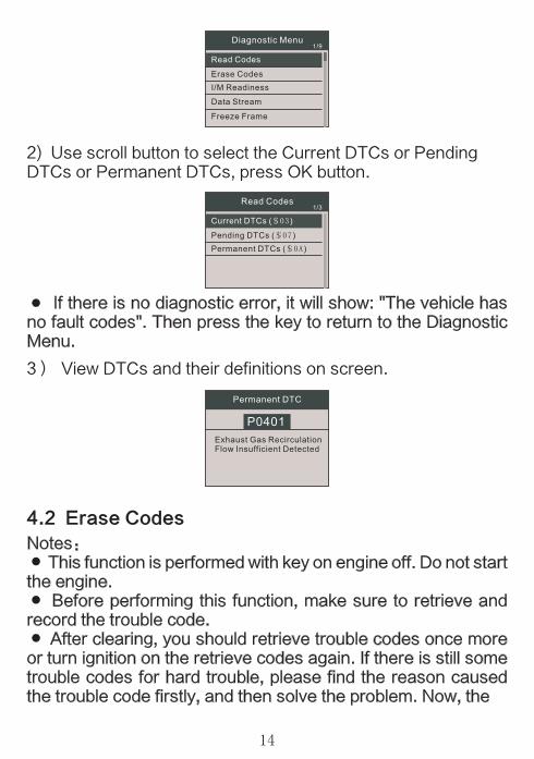
4.2 Erase Codes
2) Use scroll button to select the Current DTCs or PendingDTCs or Permanent DTCs, press OK button.
3) View DTCs and their definitions on screen.
· If there is no diagnostic error, it will show: "The vehicle hasno fault codes". Then press the key to return to the Diagnostic Menu.
Notes:· This function is performed with key on engine off. Do not startthe engine.· Before performing this function, make sure to retrieve andrecord the trouble code.· After clearing, you should retrieve trouble codes once moreor turn ignition on the retrieve codes again. If there is still some trouble codes for hard trouble, please find the reason caused the trouble code firstly, and then solve the problem. Now, the
14

4.3 I/M Readiness
trouble codes can be erased.From the Diagnostic Menu, use the UP/DOWN scroll button to select the Erase Codes, and press OK button.
1) A warning message comes up asking for your confirmation.
2) Press OK to confirm.·If the codes are cleared successfully, the followinginformation will be displayed.
I/M is the abbreviation of Inspection and Maintenance, legislated by the Government to meet federal clean-air standards. I/M Readiness indicate whether or not the various emissions-related systems on the vehicle are operating properly and are ready for inspection and maintenance testing. The purpose of I/M Readiness Monitor Status is to indicate which of the vehicle’s Monitors have run and completed their diagnosis and testing (as described in 2.5),and which ones have not yet run and completed testing and diagnosis of their designated sections of the vehicle’s emissions system.
15

The I/M Readiness Monitor Status function also can be used (after repair of a fault has been performed) to confirm that the repair has been performed correctly and/or to check for Monitor Run Status.1) From the Diagnostic Menu, use the UP/DOWN to select theI/M Readiness, and press OK button.
4.4 Data Stream The OBDII Scan Tool is a special diagnostic tool that
communicates with the vehicle’s computer. The Scan Tool lets you view “real-time” Data Stream. This information includes values (volts, rpm, temperature, speed, etc.) generated by the various vehicle sensors, switches and actuators.
Press OK1) From the Diagnostic Menu, use the UP/DOWN scrollbutton to select the Data Stream,and press OK button.
2) From the Data Stream Menu,use UP/DOWN scroll button to select the “View All Items”,and press OK button.
16

It will display all the Data Stream information.
Select a data press OK button to see the graphic information.
3) From the Data Stream Menu,use UP/DOWN scroll button to select ”View Graphic Items”,and press OK button.
4) Press to return to Diagnostic Menu.
1) From the Diagnostic Menu, use the UP/DOWN scroll button to select the“Freeze Frame”,and press OK button.
4.5 Freeze Frame When an emission-related fault occurs, certain vehicle
conditions are recorded by on-board computer. This information is referred to as freeze frame data. Freeze Data is a snapshot of the operating conditions at the time of an emission-related fault.· If DTCs were erased, Freeze Data may not be stored invehicle memory.
17

The screen will display the interface as shown below:
1)From the Diagnostic Menu , use UP/DOWN scroll button to select the O2 Sensor Test/On-Board Monitoring/Evap System Test, and press OK button.
1) Use UP/DOWN scroll button to select Vehicle Information. From the Diagnostic Menu and Press OK.
5) Press to return to Diagnostic Menu.
4.6 O2 Sensor Test/On-Board Monitoring/Evap System Test
4.7 Vehicle Information Select “Vehicle information” and press OK ,the screen will display the formation such as VIN(Vehicle Identification Number), CID(Calibration ID), and CVN(Calibration Verify Number).
2) Press to return to Diagnostic Menu.
18

Follow these steps to proceed to registration and update:1) Go to www.topdon.com and download the Topdon update files to the computer.2) Connect the tool to the USB port of the computer. It will showa storage disk in your computer and the tool’s screen displays as follows:
2) Wait a few seconds while the scan tool is reading vehicleinformation.
3) Uncompress the update files to the storage disk.
3) Press to return to Diagnostic Menu.
5. Update
19

ArtiLink201 warrants to its customers that this product will be free from all defects in materials and workmanship for a period of one(1) year from the date of the original purchase, subject to the following terms and conditions:1) The sole responsibility of ArtiLink201 under the Warranty is limited to either the repair or, at the option of Topdon, replacement of the code reader at no charge with Proof of Purchase. The sales receipt may be used for this purpose.2) This warranty does not apply to damages caused by improper use, accident, flood, lightning, or if the product was altered or repaired by anyone other than the Manufacturer’s Service Center.3) ArtiLink201 shall not be liable for any incidental or consequential damages arising from the use, misuse, or mounting of the code reader. Some states do not allow limitations may not apply to you.4) All information in this manual is based on the latest information available at the time of publication and no warranty can be made for its accuracy or completeness. ArtiLink201 reserves the right to make changes at any time without notice.
If you have any questions, please contact our local store, distributor or visit our website at www.topdon.com. If it becomes necessary to return the code reader for repair, contact our local distributor for more information.
4) The tool will upgrade the files when you plug it to vehicleOBD socket next time.
6.1 Limited One Year Warranty
6.2 Service Procedures
6. Warranty and Service
20


TOPDON Tech Co,.LTD. www.topdon.com
All Rights Reserved