Table of Contents - Norsk Standard mini enquiry/9. Plug and... · NORSOK standard D-010 Rev. 3,...
50
NORSOK standard D-010 Rev. 3, August 2004 Sidetracks, Below is a listing of the main changes 91. Definitions of suspension, temporary and permanent abandonment 9.1 General 2. Included more examples of well barrier schematics 3. Included illustrations for permanent abandonment scenarios (9.5.3) 4. Included shale formation as an annulus well barrier element (9.5.4) 5. Included flow charts for establishing permanent barriers (9.5.6 and 9.5.7) 6. Included requirements for XT removal Table of Contents 9.1 General .......................................................................................................... 1 9.2 Well barrier schematics ................................................................................. 2 9.3 Suspension .................................................................................................... 2 9.3.1 General ................................................................................................... 2 9.3.2 Well barrier schematics ........................................................................... 3 9.4 Temporary abandonment .............................................................................. 7 9.4.1 General ................................................................................................... 7 9.4.2 Well barrier schematics ........................................................................... 9 9.5 Permanent abandonment ............................................................................ 19 9.5.1 General ................................................................................................. 19 9.5.2 Well barrier schematics ......................................................................... 21 9.5.3 Examples for different permanent P&A options..................................... 29 9.5.4 Formation as well barrier element ......................................................... 31 9.5.5 Sidetracking .......................................................................................... 32 9.5.6 Section milling to establish permanent barriers ..................................... 32 9.5.7 Alternative method to establish permanent barriers .............................. 35 9.5.8 Materials................................................................................................ 36 9.6 Well control action procedures and drills ..................................................... 37 9.6.1 Well control action procedures .............................................................. 37 9.6.2 Well control action drills......................................................................... 37 9.6.3 Well control requirements...................................................................... 37 9.7 Suspension, plugging and abandonment design ......................................... 37 9.7.1 Design basis, premises and assumptions ............................................. 37 9.7.2 Load cases ............................................................................................ 38 9.8 Other topics ................................................................................................. 39 9.8.1 Risks ..................................................................................................... 39 9.8.2 Removing equipment above seabed ..................................................... 39 9.9 Vertical Xmas tree (VXT) removal .............................................................. 41 9.10 Horizontal Xmas tree removal .................................................................. 42 9 Plugging, abandonment and suspension 9.1 General This section covers requirements and guidelines pertaining tofor well integrity during plugging of wells in connection with
Transcript of Table of Contents - Norsk Standard mini enquiry/9. Plug and... · NORSOK standard D-010 Rev. 3,...
NORSOK standard D-010 Rev. 3, August 2004 Sidetracks, Below is a listing of the main changes
91. Definitions of suspension, temporary and permanent abandonment
9.1 General 2. Included more examples of well barrier schematics 3. Included illustrations for permanent abandonment scenarios (9.5.3) 4. Included shale formation as an annulus well barrier element (9.5.4) 5. Included flow charts for establishing permanent barriers (9.5.6 and 9.5.7) 6. Included requirements for XT removal
Table of Contents 9.1 General .......................................................................................................... 1 9.2 Well barrier schematics ................................................................................. 2 9.3 Suspension .................................................................................................... 2
9.3.1 General ................................................................................................... 2 9.3.2 Well barrier schematics ........................................................................... 3
9.4 Temporary abandonment .............................................................................. 7 9.4.1 General ................................................................................................... 7 9.4.2 Well barrier schematics ........................................................................... 9
9.5 Permanent abandonment ............................................................................ 19 9.5.1 General ................................................................................................. 19 9.5.2 Well barrier schematics ......................................................................... 21 9.5.3 Examples for different permanent P&A options ..................................... 29 9.5.4 Formation as well barrier element ......................................................... 31 9.5.5 Sidetracking .......................................................................................... 32 9.5.6 Section milling to establish permanent barriers ..................................... 32 9.5.7 Alternative method to establish permanent barriers .............................. 35 9.5.8 Materials................................................................................................ 36
9.6 Well control action procedures and drills ..................................................... 37 9.6.1 Well control action procedures .............................................................. 37 9.6.2 Well control action drills......................................................................... 37 9.6.3 Well control requirements ...................................................................... 37
9.7 Suspension, plugging and abandonment design ......................................... 37 9.7.1 Design basis, premises and assumptions ............................................. 37 9.7.2 Load cases ............................................................................................ 38
9.8 Other topics ................................................................................................. 39 9.8.1 Risks ..................................................................................................... 39 9.8.2 Removing equipment above seabed ..................................................... 39
9.9 Vertical Xmas tree (VXT) removal .............................................................. 41 9.10 Horizontal Xmas tree removal .................................................................. 42
9 Plugging, abandonment and suspension
9.1 General This section covers requirements and guidelines pertaining tofor well integrity during plugging of wells in connection with
NORSOK standard D-010 Rev. 3, August 2004
•a) temporary suspensionsuspension of well activities and operations, •b) temporary or permanent abandonmentpermanent abandonment of wells, •c) permanent abandonmentpermanent abandonment of a section of a well (side tracking, slot
recovery) to construct a new wellbore with a new geological well target. The purpose of this section is to describe the establishment of well barrierswell barriers by use of WBEsWBEs and additional features requiredrequirements and guidelines to execute this activity in a safe manner, with focus on isolation of permeable formations/reservoirs//reservoirs/sources of outflow, both from each other in the wellbore, and from surface. Requirements for isolation of formations, fluids and pressures for temporary and permanent abandonmentpermanent abandonment are the same. However, choice of WBEsWBEs may be different to account for abandonment time, and ability to re-enterreenter the well, or resume operations after temporary abandonment. temporary abandonment.
9.2 Well barrier schematics Well barrier schematics (WBS) shall be prepared for each well activity and operation. A final verified WBS for the well status upon completion of operations shall be in place. Samples of well barrier schematics for selected situations are presented.
9.3 Suspension
9.3.1 General
SuspensionIt is recommended that WBSs are developed as a practical method to demonstrate and illustrate the presence of the defined primary and secondary well barriers in the well, see 4.2. In the table below there are a number of typical scenarios listed, some of which are also attached as illustrations. The table is not comprehensive and schematics for the actual situations during an activity or operation should be made. of a production or injection well is defined as a well status, where the well is temporarily plugged, XT is installed, and the well barriers are monitored.
Suspension of a well under construction or intervention is defined as a well status, where the well operation is suspended without removing the well control equipment. Example: Disconnect due to WOW
Well barriers and WBE material(s) shall have sufficient integrity to meet the suspension period, including contingency. The suspended wellbore should be monitored throughout the suspension period. The following number of well barriers shall be in place to safely suspend the wellbore:
ItemSuspension DescriptionFormation Comments See
1. Temporary abandonment – Non- perforated well. Non-completed well.
9.8.1
Slettede celler
Slettede celler

NORSOK standard D-010 Rev. 3, August 2004
ItemSuspension DescriptionFormation Comments See
2. Temporary abandonment – Perforated well with BOP or production tree removed.
With well completion installed.
9.8.2
3. Permanent abandonment - Open hole. 9.8.3
4. Permanent abandonment – Perforated well. 9.8.4
5.Two well barriers
Permanent abandonment - Multibore with slotted liners or sandscreens.
Covers permanent zonal isolation of multiple reservoirs.Potential source of inflow or reservoir exposed (hydrocarbons present)
9.8.5
6.One well barrier Permanent abandonment - Slotted liners in multiple reservoirs.Formation with normal pressure (or less)
Applies also to slot recovery/ side tracks, etc.
9.8.6
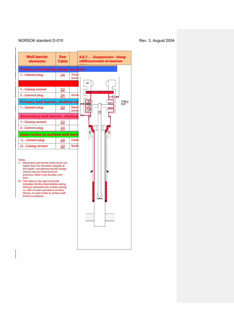
7. Suspension - Hang-off/disconnect of mariner riser. Hang-off drill pipe.
9.8.7
Slettede celler
Slettede celler
Slettede celler
Slettede celler
Slettede celler

NORSOK standard D-010 Rev. 3, August 2004
9.39.3.2 Well barrier acceptance criteriaschematics
9.3.1 Function and type of well barriers For wells to be permanently abandoned, with several sources of inflow, the usual; one primary and one secondary well barrier, do not suffice. Hence, this subclause covers all well barriers and the functions they are intended to fulfil which may be necessary in abandonment scenarios. These well barriers may, however, not be applicable for wells where continued operations are planned, where the wellhead/ well control equipment is utilised and capable, as a secondary well barrier, to cover any source of inflow in the well. This also means that some terms used in this subclause are only applicable in the context of suspension and abandonment of wells and wellbores.
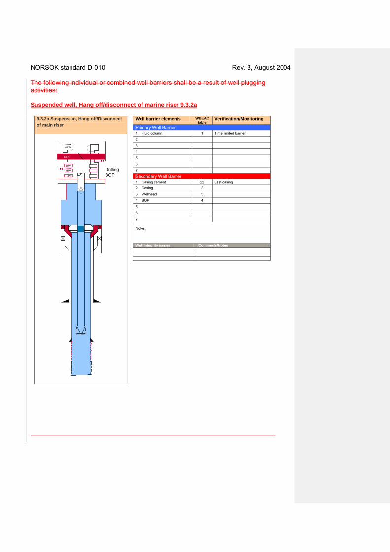
NORSOK standard D-010 Rev. 3, August 2004 The following individual or combined well barriers shall be a result of well plugging activities: Suspended well, Hang off/disconnect of marine riser 9.3.2a
UPR
LPR
APR
Drilling BOP
SSR
Well barrier elements WBEAC table
Verification/Monitoring
Primary Well Barrier 1. Fluid column 1 Time limited barrier
2.
3.
4.
5.
6.
7.
Secondary Well Barrier 1. Casing cement 22 Last casing
2. Casing 2
3. Wellhead 5
4. BOP 4
5.
6.
7. Notes: Well Integrity issues Comments/Notes
9.3.2a Suspension, Hang off/Disconnect of main riser
MPR
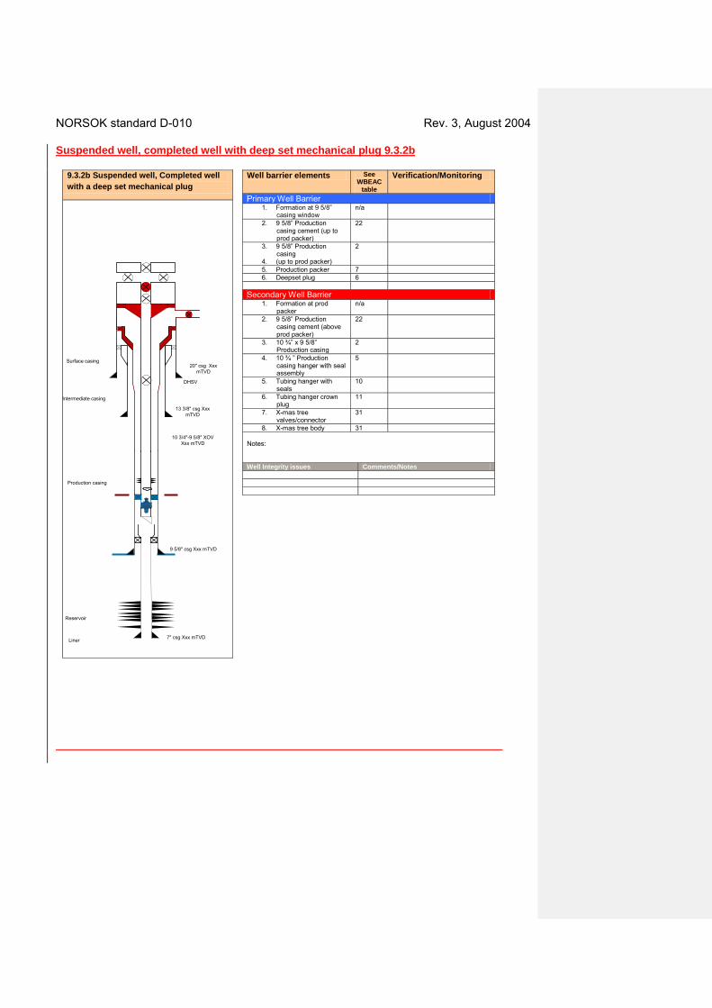
NORSOK standard D-010 Rev. 3, August 2004 Suspended well, completed well with deep set mechanical plug 9.3.2b
Well barrier elements See WBEAC
table
Verification/Monitoring
Primary Well Barrier 1. Formation at 9 5/8”
casing window n/a
2. 9 5/8” Production casing cement (up to prod packer)
22
3. 9 5/8” Production casing
4. (up to prod packer)
2
5. Production packer 7 6. Deepset plug 6
Secondary Well Barrier
1. Formation at prod packer
n/a
2. 9 5/8” Production casing cement (above prod packer)
22
3. 10 ¾” x 9 5/8” Production casing
2
4. 10 ¾ ” Production casing hanger with seal assembly
5
5. Tubing hanger with seals
10
6. Tubing hanger crown plug
11
7. X-mas tree valves/connector
31
8. X-mas tree body 31 Notes: Well Integrity issues Comments/Notes
9.3.2b Suspended well, Completed well with a deep set mechanical plug
13 3/8" csg Xxx mTVD
10 3/4"-9 5/8" XOV Xxx mTVD
20" csg Xxx mTVD
PT
Reservoir
7" csg Xxx mTVD
Surface casing
Intermediate casing
9 5/8" csg Xxx mTVD
Production casing
Liner
DHSV
NORSOK standard D-010 Rev. 3, August 2004
9.4 Temporary abandonment
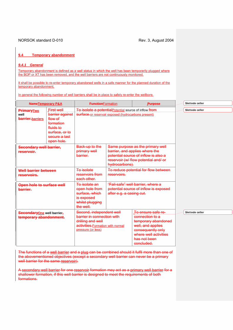
9.4.1 General Temporary abandonment is defined as a well status in which the well has been temporarily plugged where the BOP or XT has been removed, and the well barriers are not continuously monitored.
It shall be possible to re-enter temporary abandoned wells in a safe manner for the planned duration of the temporary abandonment.
In general the following number of well barriers shall be in place to safely re-enter the wellbore.
NameTemporary P&A FunctionFormation Purpose
PrimaryTwo well barrier.barriers
First well barrier against flow of formation fluids to surface, or to secure a last open hole.
To isolate a potentialPotential source of inflow from surface.or reservoir exposed (hydrocarbons present)
Secondary well barrier, reservoir.
Back-up to the primary well barrier.
Same purpose as the primary well barrier, and applies where the potential source of inflow is also a reservoir (w/ flow potential and/ or hydrocarbons).
Well barrier between reservoirs.
To isolate reservoirs from each other.
To reduce potential for flow between reservoirs.
Open hole to surface well barrier.
To isolate an open hole from surface, which is exposed whilst plugging the well.
“Fail-safe” well barrier, where a potential source of inflow is exposed after e.g. a casing cut.
SecondaryOne well barrier, temporary abandonment.
Second, independent well barrier in connection with drilling and well activities.Formation with normal pressure (or less)
To ensure safe re-connection to a temporary abandoned well, and applies consequently only where well activities has not been concluded.
The functions of a well barrier and a plug can be combined should it fulfil more than one of the abovementioned objectives (except a secondary well barrier can never be a primary well barrier for the same reservoir). A secondary well barrier for one reservoir formation may act as a primary well barrier for a shallower formation, if this well barrier is designed to meet the requirements of both formations.
Slettede celler
Slettede celler
Slettede celler

NORSOK standard D-010 Rev. 3, August 2004 9.3.2 Positioning of well barriers Well barriers should be installed as close to the potential source of inflow as possible, covering all possible leak paths. The primary and secondary well barriers shall be positioned at a depth where the estimated formation fracture pressure at the base of the plug is in excess of the potential internal pressure. The final position of the well barrier/WBEs shall be verified. 9.3.3 Materials The materials used in well barriers for plugging of wells shall withstand the load/ environmental conditions it may be exposed to for the time the well will be abandoned. Tests should be performed to document long term integrity of plugging materials used. 9.3.4 Leak testing and verification When inflow testing or leak testing from above to verify the integrity of a well barrier is not possible, or when this may not give conclusive results, other means of ensuring proper installation of a well barrier shall be used. Verification through assessment of job planning and actual job performance parameters are options available. Inflow tests shall be documented.
9.3.59.1.1 Sidetracking
The original wellbore shall be permanently abandoned prior to a side-track/ slot recovery.For
9.3.6 Suspension Suspension of operations requires the same number of well barriers as other abandonment activities. However, the need for WBE testing, and verification, can be compensated by monitoring of its performance, such as fluid level/ pressure development above well barriers. Well fluids (see Table 1) may in such cases be qualified as a WBE.
9.3.7 Temporary abandonment It shall be possible to re-enter temporarily abandoned wells in a safe manner. Integrity of materials used for temporary abandonment should be ensured for the planned wellbores, the selected WBE material(s) shall have sufficient integrity to meet the abandonment period times two. Hence, a mechanical well barrier may be acceptable for temporary abandonment, subject to type, planned abandonment period and subsurface environment. Degradation of casing body should be considered for longerPrior to temporary abandonment scenarios., the future plans for the well shall be documented. Temporarily abandoned subsea wellheads and templateswells shall be protected from external loads in areas with fishing activities, or other seabed activities etc. Hence for. For deep water wells, temporary seabed protection can be omitted if there is confirmation of no such activities in the area and at the depth of the abandoned seabed installations.
For temporary abandoned surface completed wells, it shall be possible to monitor the pressure in the A annulus and in the tubing.
For temporary abandoned subsea completed wells that are planned to be abandoned for more than one year, a yearly program for monitoring and observation shall be established and implemented.
NORSOK standard D-010 Rev. 3, August 2004 The pressure in the tubing and annulus above the reservoir well barrier (“A” annulus) shall be monitored if a subsea completed well is planned to be abandoned for more than one year. An acceptable alternative if or not tied back to a production facility. The following requirements are to be met:
• Production/injection packer and tubing hanger is pressure tested. • Tubing is pressure tested. • The DHSV is closed and pressure/function tested. • All valves in the X-mas tree have been pressure tested with zero leak rate/function tested and are
closed. • For wells with horizontal X-mas trees, the tree cap and tubing hanger crown plug shall be pressure
tested.
If monitoring is not practicable , an acceptable alternative may be to install a deep set well barrier element plug. For surface completed wells, it should be possible to monitor the pressure in the “A” annulus and in the last tubular that was installed (production tubing, casing).

NORSOK standard D-010 Rev. 3, August 2004
9.4.2 Well barrier schematics
Temporary abandonment, reservoir exposed 9.4.2a
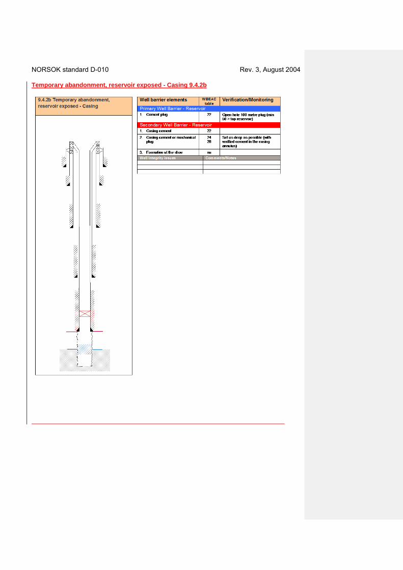
NORSOK standard D-010 Rev. 3, August 2004 Temporary abandonment, reservoir exposed - Casing 9.4.2b

NORSOK standard D-010 Rev. 3, August 2004 Temporary abandonment, no permeable formation exposed - Liner 9.4.2c
Well barrier elements WBEAC table
Verification/Monitoring
Primary Well Barrier – Open hole 1. Cement plug 24
28 Set as deep as possible with verified cement in casing annulus
2. Casing cement 22
3. Formation at the shoe na
Secondary Well Barrier – Open hole 1. Casing cement 22
2. Casing cement or mechanical plug
24 28
Shallow plug
3. Liner top packer 43 Grade: V1
4. Formation Well Integrity issues Comments/Notes
9.4.2c Temporary abandonment, no permeable formation exposed - Liner
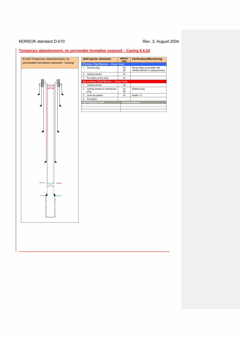
NORSOK standard D-010 Rev. 3, August 2004 Temporary abandonment, no permeable formation exposed – Casing 9.4.2d
Well barrier elements WBEAC table
Verification/Monitoring
Primary Well Barrier – Open hole 1. Cement plug 24
28 Set as deep as possible with verified cement in casing annulus
2. Casing cement 22
3. Formation at the shoe na
Secondary Well Barrier – Open hole 1. Casing cement 22
2. Casing cement or mechanical plug
24 28
Shallow plug
3. Liner top packer 43 Grade: V1
4. Formation Well Integrity issues Comments/Notes
9.4.2d Temporary abandonment, no permeable formation exposed - Casing
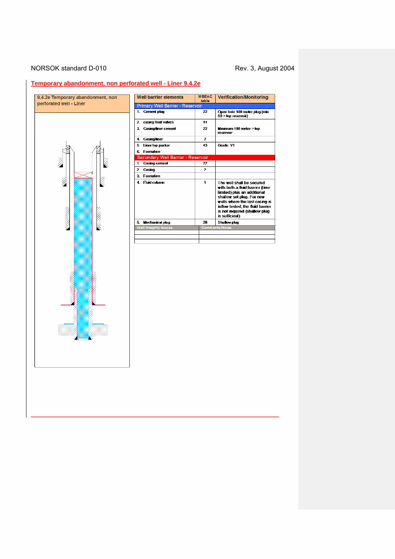
NORSOK standard D-010 Rev. 3, August 2004 Temporary abandonment, non perforated well - Liner 9.4.2e

NORSOK standard D-010 Rev. 3, August 2004 Temporary abandonment, non perforated well - Casing 9.4.2f

NORSOK standard D-010 Rev. 3, August 2004 Temporary abandonment, impermeable formation with over pressure, non perforated 9.4.2g
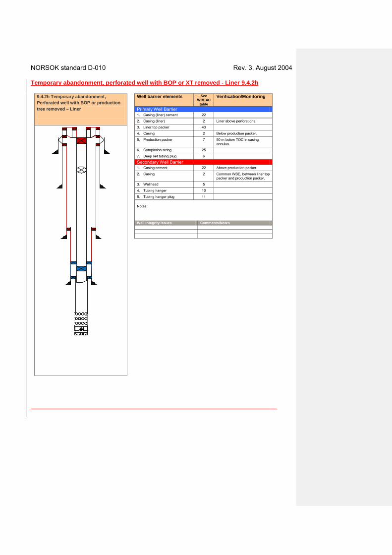
NORSOK standard D-010 Rev. 3, August 2004 Temporary abandonment, perforated well with BOP or XT removed - Liner 9.4.2h
Well barrier elements See WBEAC
table
Verification/Monitoring
Primary Well Barrier 1. Casing (liner) cement 22
2. Casing (liner) 2 Liner above perforations.
3. Liner top packer 43
4. Casing 2 Below production packer.
5. Production packer 7 50 m below TOC in casing annulus.
6. Completion string 25
7. Deep set tubing plug 6
Secondary Well Barrier 1. Casing cement 22 Above production packer.
2. Casing 2 Common WBE, between liner top packer and production packer.
3. Wellhead 5
4. Tubing hanger 10
5. Tubing hanger plug 11 Notes: Well Integrity issues Comments/Notes
9.4.2h Temporary abandonment, Perforated well with BOP or production tree removed – Liner

NORSOK standard D-010 Rev. 3, August 2004 Temporary abandonment, perforated well with BOP or XT removed - Casing 9.4.2i
Well barrier elements See WBEAC
table
Verification/Monitoring
Primary Well Barrier 1. Casing cement 22
2. Casing 2 Above perforations.
3. Production packer 7
4. Completion string 25
5. Deep set tubing plug 6
Secondary Well Barrier 1. Casing cement 22 Intermediate casing.
2. Casing 2 Intermediate casing.
3. Wellhead 5
4. Tubing hanger 10
5. Tubing hanger plug 11 Well Integrity issues Comments/Notes
9.4.2i Temporary abandonment, Perforated well with BOP or production tree removed - Casing
NORSOK standard D-010 Rev. 3, August 2004
9.3.89.5 Permanent abandonment
9.3.8.19.5.1 General This section covers requirements and guidelines for well integrity during permanent abandonment. Permanently plugged wells shall be abandoned with an eternal perspective, i.e. for the purpose of evaluating the effect on taking into account the well barriers installed aftereffects of any foreseeable chemical and geological process has taken placeprocesses. The following number of well barriers to the external environment shall be fulfilled.
Permanent P&A Formation
Two well barriers Potential source of inflow or reservoir exposed (hydrocarbons present)
One well barrier Formation with normal pressure (or less)
The following individual or combined well barriers/isolations shall be a result of well plugging activities.
Name Function Requirement to depth position
Primary well barrier
First well barrier against a potential source of inflow. To isolate a potential source of inflow from flowing to surface/seabed
The base of the barrier shall be positioned at a depth where wellbore integrity is higher than potential pressure below, see 4.2.3.5.7 Testing of formation.
Secondary well barrier
Backup to the primary well barrier, against a potential source of inflow.
As above.
Crossflow well barrier
To prevent flow between formations (where crossflow is not acceptable). May also function as primary well barrier for the reservoir below.
As above.
Environmental isolation plug*
To isolate the full cross sectional wellbore. To prevent movement of wellbore fluids to the environment.
The selected position should be documented**.
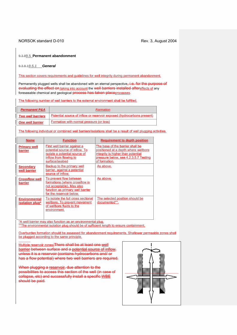
*A well barrier may also function as an environmental plug. **The environmental isolation plug should be of sufficient length to ensure containment. Overburden formation should be assessed for abandonment requirements. Shallower permeable zones shall be plugged according to the same principle. Multiple reservoir zones/There shall be at least one well barrier between surface and a potential source of inflow, unless it is a reservoir (contains hydrocarbons and/ or has a flow potential) where two well barriers are required. When plugging a reservoir, due attention to the possibilities to access this section of the well (in case of collapse, etc) and successfully install a specific WBE should be paid.
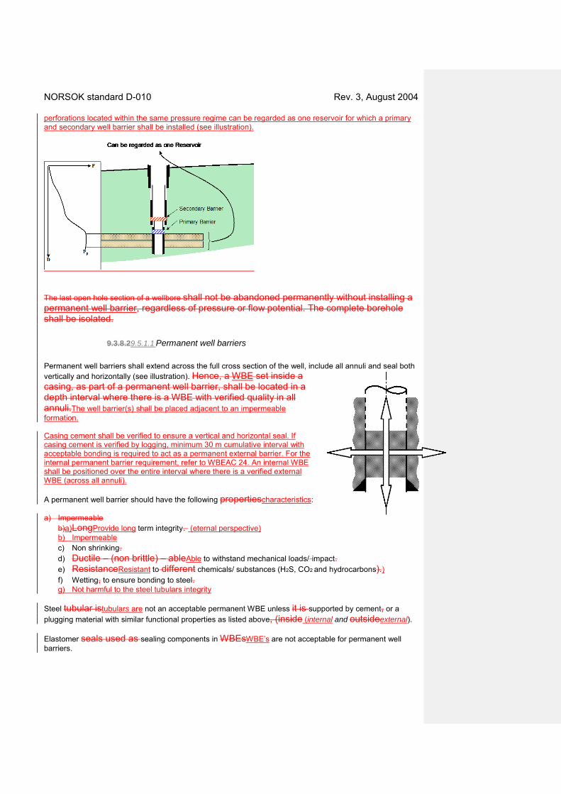
NORSOK standard D-010 Rev. 3, August 2004 perforations located within the same pressure regime can be regarded as one reservoir for which a primary and secondary well barrier shall be installed (see illustration).
The last open hole section of a wellbore shall not be abandoned permanently without installing a permanent well barrier, regardless of pressure or flow potential. The complete borehole shall be isolated.
9.3.8.29.5.1.1 Permanent well barriers Permanent well barriers shall extend across the full cross section of the well, include all annuli and seal both vertically and horizontally (see illustration). Hence, a WBE set inside a casing, as part of a permanent well barrier, shall be located in a depth interval where there is a WBE with verified quality in all annuli.The well barrier(s) shall be placed adjacent to an impermeable formation. Casing cement shall be verified to ensure a vertical and horizontal seal. If casing cement is verified by logging, minimum 30 m cumulative interval with acceptable bonding is required to act as a permanent external barrier. For the internal permanent barrier requirement, refer to WBEAC 24. An internal WBE shall be positioned over the entire interval where there is a verified external WBE (across all annuli). A permanent well barrier should have the following propertiescharacteristics: a) Impermeable
b)a) LongProvide long term integrity. (eternal perspective) b) Impermeable c) Non shrinking. d) Ductile – (non brittle) – ableAble to withstand mechanical loads/ impact. e) ResistanceResistant to different chemicals/ substances (H2S, CO2 and hydrocarbons).) f) Wetting, to ensure bonding to steel. g) Not harmful to the steel tubulars integrity
Steel tubular istubulars are not an acceptable permanent WBE unless it is supported by cement, or a plugging material with similar functional properties as listed above, (inside (internal and outsideexternal). Elastomer seals used as sealing components in WBEsWBE’s are not acceptable for permanent well barriers.

NORSOK standard D-010 Rev. 3, August 2004 The presence and pressure integrity of casing cement shall be verified to assess the along hole pressure integrity of this WBE. The cement in annulus will not qualify as a WBE across the well (see illustration). Open hole cement plugs can be used as a well barrier between reservoirs. It should, as far as practicably possible, also be used as a primary well barrier, see Table 24. Cement in the liner lap, which has not been leak is accepted as a permanent WBE when pressure tested from above (before a possible installation of liner top packer has been set) shall not be regarded a permanent WBE.). Removal of downhole equipment is not required as long as the integrity of the well barriers is achieved. Control cables and lines shall be removed from areas where permanent well barriers are installed, sinceif they maycan create vertical leak paths through the well barrier. Completions should be designed to facilitate the setting of annular cement plugs as a well barrier. When well completion tubulars are left in hole the well and permanent plugs well barriers are installed through and around the tubular, reliable methods and procedures to install and verify position of the plug inside the tubular and in the tubular tubing and annulus, the position and integrity of the barriers shall be established. verified. Special requirements If it can be documented that placing one continuous cement (with compensating measures ref to EAC 24) plug is as reliable as two independent cement plugs to establish an internal barrier(s), this may be acceptable. 9.3.8.3 Multiple reservoir zones/ perforations located within the same pressure regime, isolated with a well barrier in between, can be regarded as one reservoir for which a primary and secondary well barrier shall be installed (see illustration).
9.49.5.2 Well barrier elements acceptance criteriaschematics
9.4.1 General Subclause 9.8 lists the WBEs that constitute the primary and secondary barriers for situations that are illustrated.
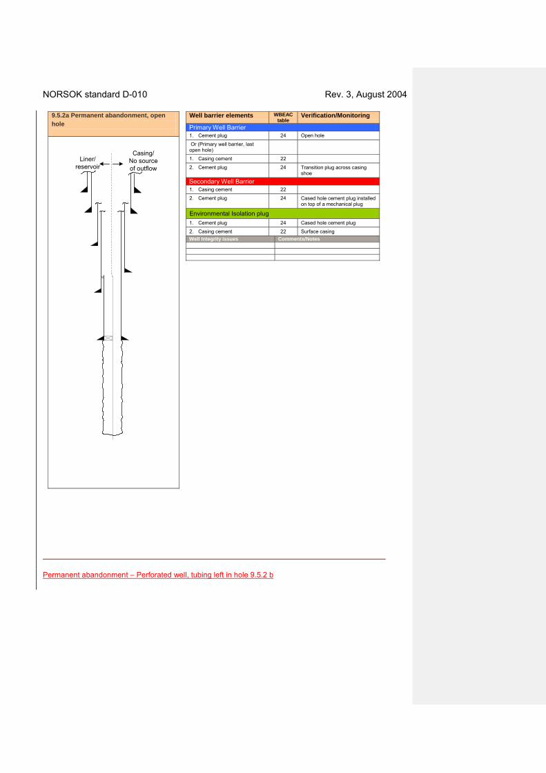
9.4.2 Additional well barrier elements (WBEs) acceptance criteria Permanent abandonment - Open hole 9.5.2 a
NORSOK standard D-010 Rev. 3, August 2004
Casing/No sourceof outflow
Liner/reservoir
Well barrier elements WBEAC table
Verification/Monitoring
Primary Well Barrier 1. Cement plug 24 Open hole
Or (Primary well barrier, last open hole)
1. Casing cement 22
2. Cement plug 24 Transition plug across casing shoe
Secondary Well Barrier 1. Casing cement 22
2. Cement plug 24 Cased hole cement plug installed on top of a mechanical plug
Environmental Isolation plug
1. Cement plug 24 Cased hole cement plug
2. Casing cement 22 Surface casing Well Integrity issues Comments/Notes
9.5.2a Permanent abandonment, open hole
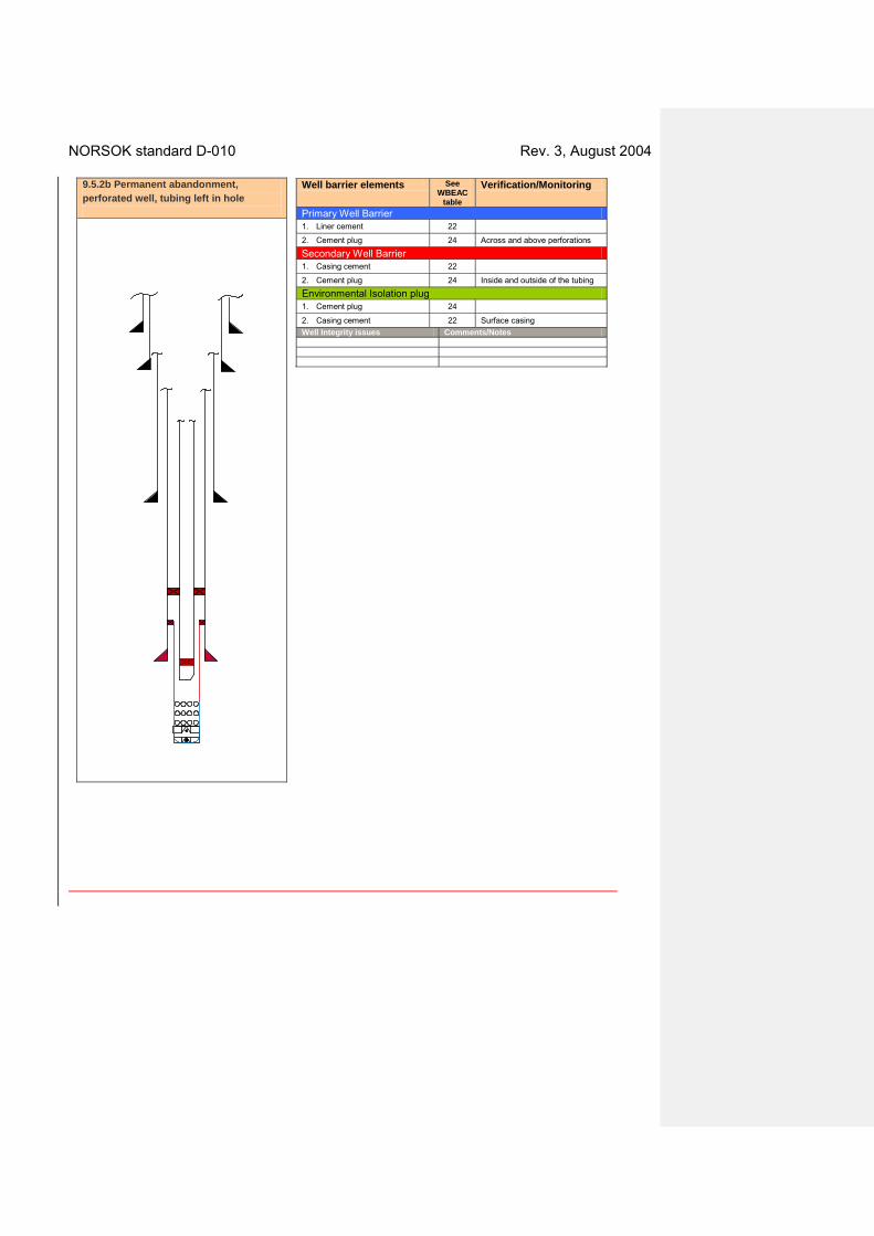
Permanent abandonment – Perforated well, tubing left in hole 9.5.2 b
NORSOK standard D-010 Rev. 3, August 2004
Well barrier elements See WBEAC
table
Verification/Monitoring
Primary Well Barrier 1. Liner cement 22
2. Cement plug 24 Across and above perforations
Secondary Well Barrier 1. Casing cement 22
2. Cement plug 24 Inside and outside of the tubing
Environmental Isolation plug 1. Cement plug 24
2. Casing cement 22 Surface casing Well Integrity issues Comments/Notes
9.5.2b Permanent abandonment, perforated well, tubing left in hole

NORSOK standard D-010 Rev. 3, August 2004 Permanent abandonment – Perforated well, tubing removed 9.5.2 c
Well barrier elements See WBEAC
table
Verification/Monitoring
Primary Well Barrier 1. Liner cement 22
2. Cement plug 24 Across and above perforations
Secondary Well Barrier 1. Casing cement 22
2. Cement plug 24 Across the liner plug.
Environmental Isolation plug 1. Cement plug 24
2. Casing cement 22 Surface casing Well Integrity issues Comments/Notes
9.5.2c Permanent abandonment, perforated well, tubing removed

NORSOK standard D-010 Rev. 3, August 2004 Permanent abandonment, Multi bore with slotted liners or sand screens – with plug 9.5.2d
Well barrier elements WBEAC table
Verification/Monitoring
Primary Well Barrier - Reservoir 1. Cement plug 22 Across and above the
perforations
Secondary Well Barrier - Reservoir 1. Casing cement 22
2. Casing cement 24 28
Across the liner plug
Environmental Isolation plug
1. Cement plug 24
2. Casing cement 22 Surface casing Well Integrity issues Comments/Notes
9.5.2d Permanent abandonment, multibore with slotted liners or sand screens – with plug

NORSOK standard D-010 Rev. 3, August 2004 Permanent abandonment, Multi bore with slotted liners or sand screens – without plug 9.5.2e
Well barrier elements WBEAC table
Verification/Monitoring
Primary Well Barrier – Reservoir 1. Cement plug 22 Across and above the
perforations
Secondary Well Barrier – Reservoir 1. Casing cement 22
2. Casing cement or mechanical plug
24 28
Across the liner plug
Environmental Isolation plug
1. Cement plug 24
2. Casing cement 22 Surface casing Well Integrity issues Comments/Notes
9.5.2e Permanent abandonment, multibore with slotted liners or sand screens – without plug
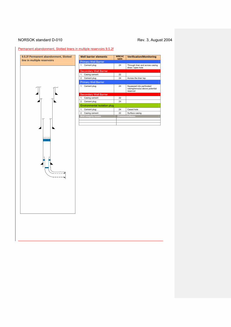
NORSOK standard D-010 Rev. 3, August 2004 Permanent abandonment, Slotted liners in multiple reservoirs 9.5.2f
Well barrier elements WBEAC table
Verification/Monitoring
Primary Well Barrier 1. Cement plug 24 Through liner and across casing
shoe / open hole
Secondary Well Barrier 1. Casing cement 22
2. Cement plug 24 Across the liner top
Primary Well Barrier 1. Cement plug 24 Squeezed into perforated
casing/annulus above potential reservoir
Secondary Well Barrier 1. Casing cement 22
2. Cement plug 24
Environmental Isolation plug 1. Cement plug 24 Cased hole
2. Casing cement 22 Surface casing Well Integrity issues Comments/Notes
9.5.2f Permanent abandonment, Slotted line in multiple reservoirs
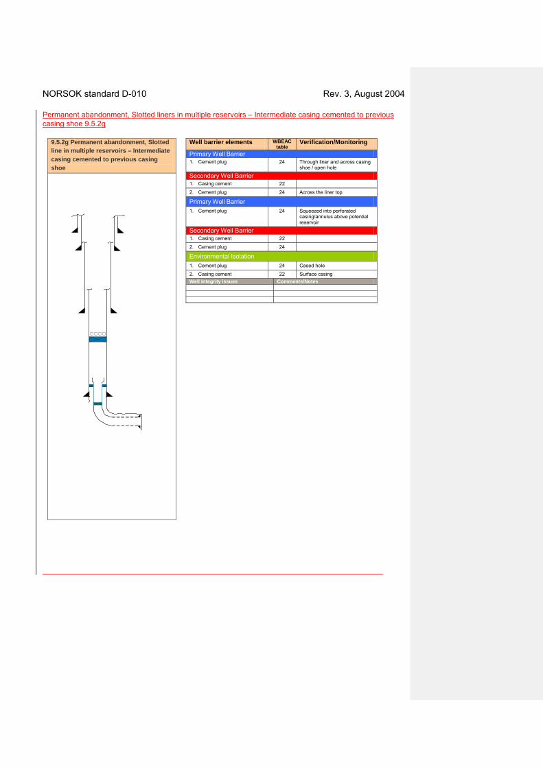
NORSOK standard D-010 Rev. 3, August 2004 Permanent abandonment, Slotted liners in multiple reservoirs – Intermediate casing cemented to previous casing shoe 9.5.2g
Well barrier elements WBEAC table
Verification/Monitoring
Primary Well Barrier 1. Cement plug 24 Through liner and across casing
shoe / open hole
Secondary Well Barrier 1. Casing cement 22
2. Cement plug 24 Across the liner top
Primary Well Barrier 1. Cement plug 24 Squeezed into perforated
casing/annulus above potential reservoir
Secondary Well Barrier 1. Casing cement 22
2. Cement plug 24
Environmental Isolation 1. Cement plug 24 Cased hole
2. Casing cement 22 Surface casing Well Integrity issues Comments/Notes
9.5.2g Permanent abandonment, Slotted line in multiple reservoirs – Intermediate casing cemented to previous casing shoe
NORSOK standard D-010 Rev. 3, August 2004
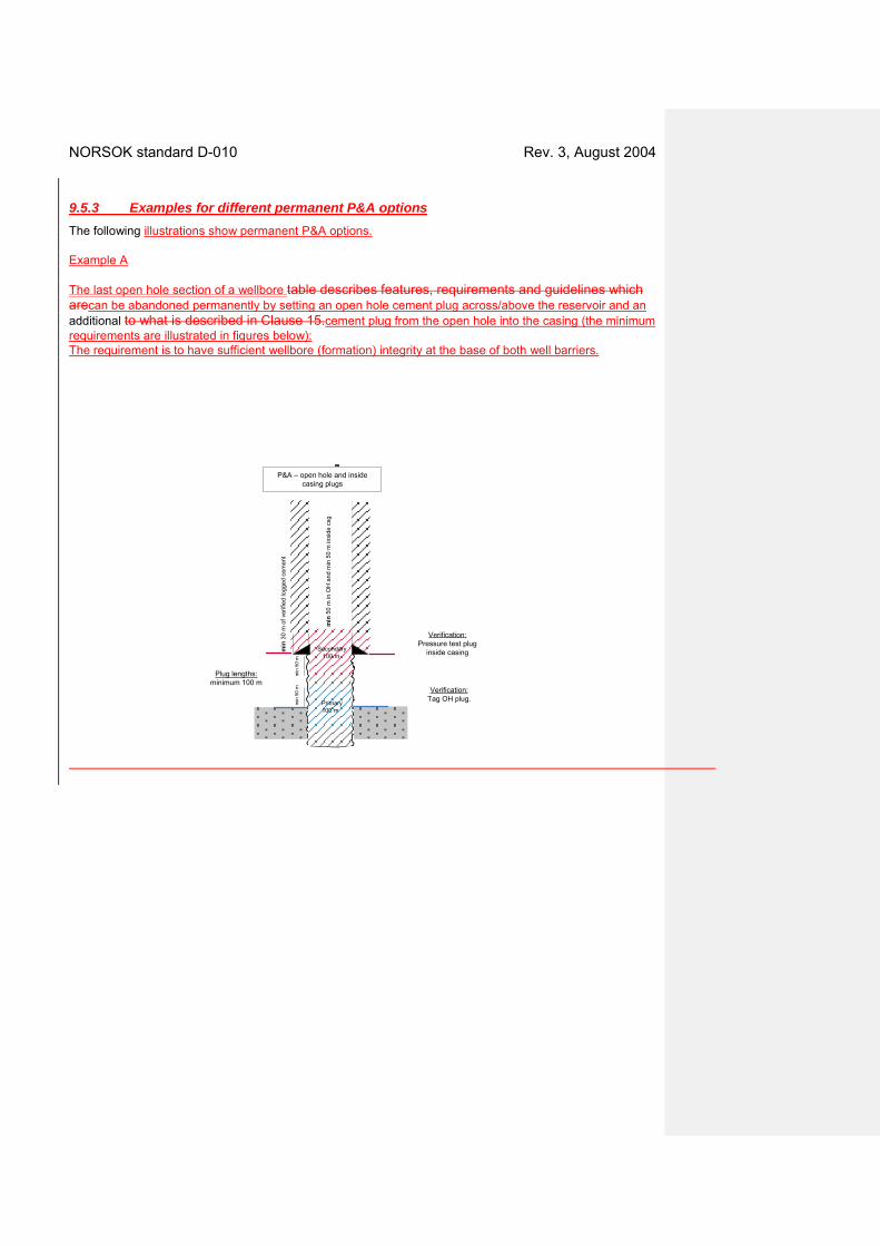
9.5.3 Examples for different permanent P&A options The following illustrations show permanent P&A options. Example A The last open hole section of a wellbore table describes features, requirements and guidelines which arecan be abandoned permanently by setting an open hole cement plug across/above the reservoir and an additional to what is described in Clause 15.cement plug from the open hole into the casing (the minimum requirements are illustrated in figures below): The requirement is to have sufficient wellbore (formation) integrity at the base of both well barriers.
Secondary100 m
Verification:Tag OH plug.
P&A – open hole and inside casing plugs
Plug lengths: minimum 100 m
min
50
m
min
30
m o
f ver
ified
logg
ed c
emen
t
min
50
m
Primary100 m
Verification:Pressure test plug
inside casing
min
50
m in
OH
and
min
50
m in
side
csg
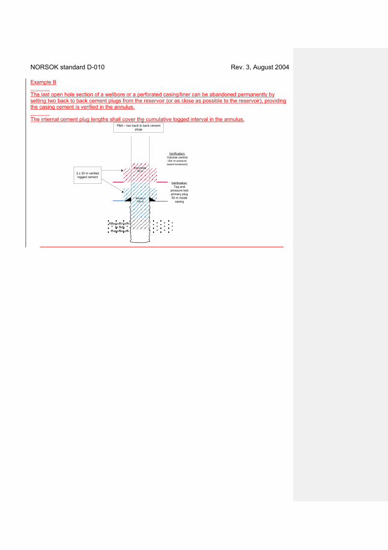
NORSOK standard D-010 Rev. 3, August 2004 Example B The last open hole section of a wellbore or a perforated casing/liner can be abandoned permanently by setting two back to back cement plugs from the reservoir (or as close as possible to the reservoir), providing the casing cement is verified in the annulus. The internal cement plug lengths shall cover the cumulative logged interval in the annulus.
Reservoir/perm. fm with
overpressure
Secondary50 m
Verification:Tag and
pressure test primary plug 50 m inside
casing
P&A – two back to back cement plugs
2 x 30 m verified logged cement
Primary100 m
Verification:Volume control(Set on pressure
tested fundament)
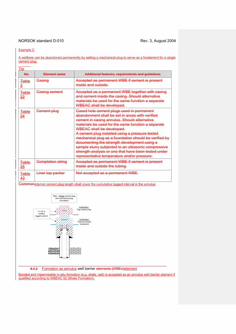
NORSOK standard D-010 Rev. 3, August 2004 Example C A wellbore can be abandoned permanently by setting a mechanical plug to serve as a fundament for a single cement plug. The
No. Element name Additional features, requirements and guidelines
Table 2
Casing Accepted as permanent WBE if cement is present inside and outside.
Table 22
Casing cement Accepted as a permanent WBE together with casing and cement inside the casing. Should alternative materials be used for the same function a separate WBEAC shall be developed.
Table 24
Cement plug Cased hole cement plugs used in permanent abandonment shall be set in areas with verified cement in casing annulus. Should alternative materials be used for the same function a separate WBEAC shall be developed. A cement plug installed using a pressure tested mechanical plug as a foundation should be verified by documenting the strength development using a sample slurry subjected to an ultrasonic compressive strength analysis or one that have been tested under representative temperature and/or pressure.
Table 25
Completion string Accepted as permanent WBE if cement is present inside and outside the tubing.
Table 43
Liner top packer Not accepted as a permanent WBE.
Commoninternal cement plug length shall cover the cumulative logged interval in the annulus
Primary
Verification:Pressure tested
fundament
P&A – Single cement plug with mechanical plug
foundation
Secondary
Reservoir/ perm. fm with overpressure
Verification:Tag cement plug
2 x 30 m verified
logged cement
9.4.3 Formation as annulus well barrier elements (WBEs)element
Bonded and impermeable in-situ formation (e.g. shale, salt) is accepted as an annulus well barrier element if qualified according to WBEAC 52 (Shale Formation).

NORSOK standard D-010 Rev. 3, August 2004 9.5.4 Sidetracking
A risk analysis shall be performed and risk reducing measures applied to reduce the risk as low as reasonable practicable, see 4.2.3.3. The original wellbore should be permanently abandoned prior to a side-track/ slot recovery. A well barrier can be shared to function as well barrier for more than one well bore.
9.5.5 Section milling to establish permanent barriers The following table describes risk reducing measures thatmethod can be applied when a WBEsection milling is required to establish well barriers.
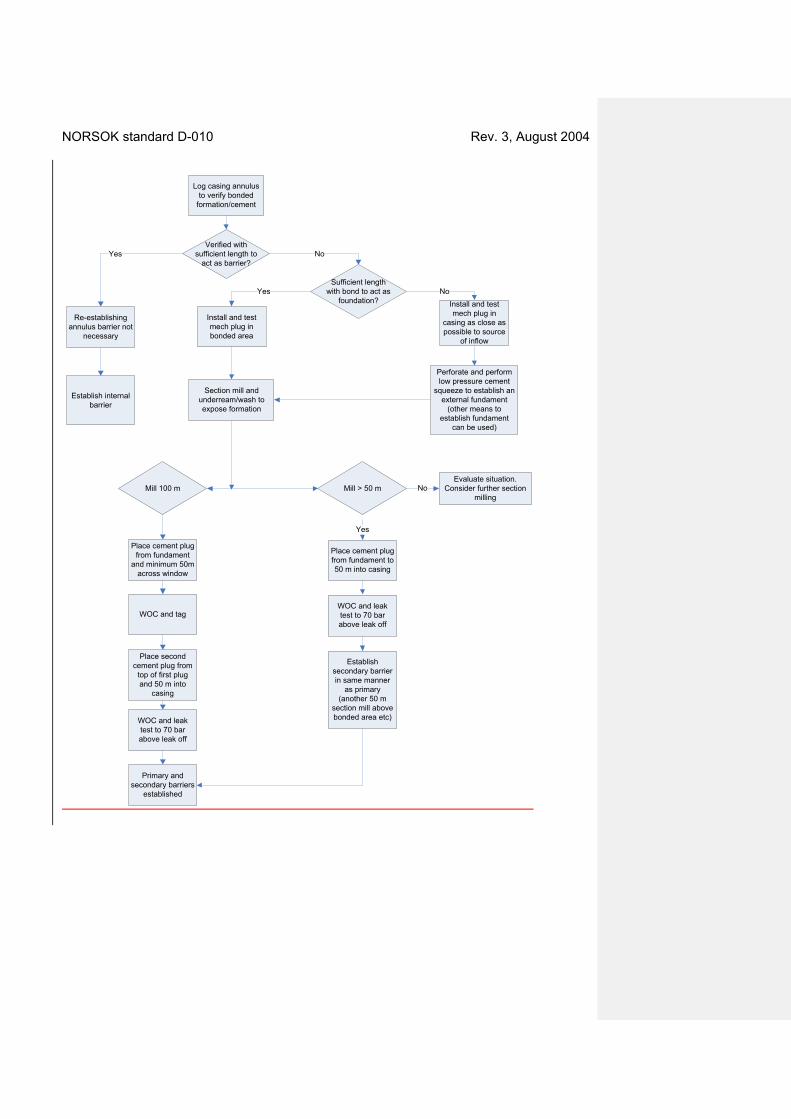
NORSOK standard D-010 Rev. 3, August 2004
Log casing annulus to verify bonded
formation/cement
Verified with sufficient length to
act as barrier?
Sufficient length with bond to act as
foundation?
Place cement plug from fundament
and minimum 50m across window
Install and test mech plug in bonded area
WOC and tag
Place second cement plug from
top of first plug and 50 m into
casing
WOC and leak test to 70 bar above leak off
Yes No
YesInstall and test mech plug in
casing as close as possible to source
of inflow
Perforate and perform low pressure cement
squeeze to establish an external fundament
(other means to establish fundament
can be used)
Section mill and underream/wash to expose formation
No
Mill 100 m Mill > 50 mEvaluate situation.
Consider further section milling
Place cement plug from fundament to 50 m into casing
WOC and leak test to 70 bar above leak off
Establish secondary barrier in same manner
as primary (another 50 m
section mill above bonded area etc)
No
Yes
Primary and secondary barriers
established
Re-establishing annulus barrier not
necessary
Establish internal barrier
NORSOK standard D-010 Rev. 3, August 2004
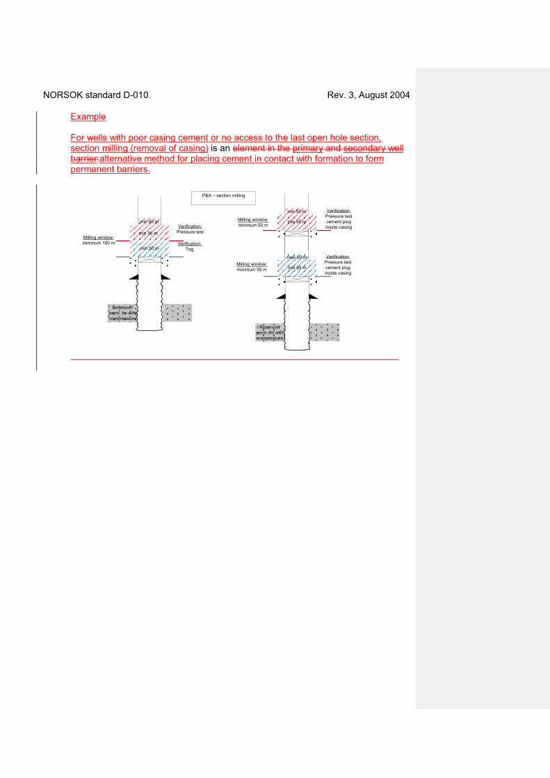
Example For wells with poor casing cement or no access to the last open hole section, section milling (removal of casing) is an element in the primary and secondary well barrier:alternative method for placing cement in contact with formation to form permanent barriers.
Milling window: minimum 100 m
P&A – section milling
Verification:Tag
Verification:Pressure test
min 50 m
min 50 m
min 50 m Milling window: minimum 50 m
Verification:Pressure test cement plug inside casing
min 50 m
max 50 m
min 50 m
min 50 m
Reservoir/ perm. fm with overpressure
Reservoir/ perm. fm with overpressure
Verification:Pressure test cement plug inside casing
Milling window: minimum 50 m
NORSOK standard D-010 Rev. 3, August 2004
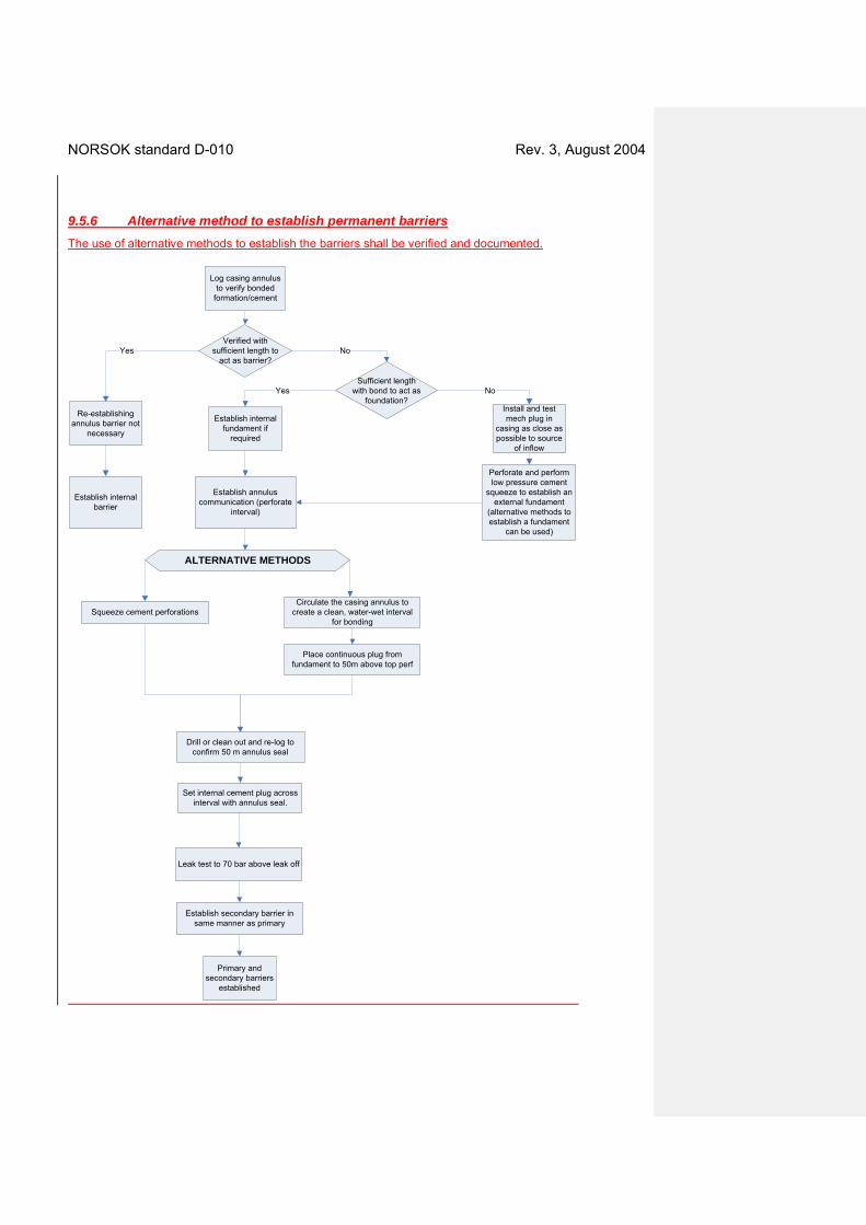
9.5.6 Alternative method to establish permanent barriers The use of alternative methods to establish the barriers shall be verified and documented.
Log casing annulus
to verify bonded formation/cement
Verified with sufficient length to
act as barrier?
Re-establishing annulus barrier not
necessary
Sufficient length with bond to act as
foundation?
Establish internal fundament if
required
Yes No
Yes
Install and test mech plug in
casing as close as possible to source
of inflow
Perforate and perform low pressure cement
squeeze to establish an external fundament
(alternative methods to establish a fundament
can be used)
Establish annulus communication (perforate
interval)
No
Place continuous plug from fundament to 50m above top perf
Establish internal barrier
Circulate the casing annulus to create a clean, water-wet interval
for bonding
Establish secondary barrier in same manner as primary
Primary and secondary barriers
established
Squeeze cement perforations
Leak test to 70 bar above leak off
Drill or clean out and re-log to confirm 50 m annulus seal
Set internal cement plug across interval with annulus seal.
ALTERNATIVE METHODS
NORSOK standard D-010 Rev. 3, August 2004
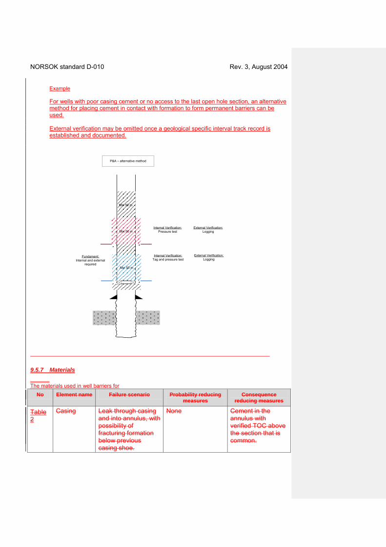
Example For wells with poor casing cement or no access to the last open hole section, an alternative method for placing cement in contact with formation to form permanent barriers can be used. External verification may be omitted once a geological specific interval track record is established and documented.
Min 50 m
Min 50 m
Min 50 m
Internal Verification:Tag and pressure test
Internal Verification:Pressure test
External Verification:Logging
External Verification:Logging
Fundament:Internal and external
required
P&A – alternative method
9.5.7 Materials The materials used in well barriers for
No Element name Failure scenario Probability reducing measures
Consequence reducing measures
Table 2
Casing Leak through casing and into annulus, with possibility of fracturing formation below previous casing shoe.
None Cement in the annulus with verified TOC above the section that is common.

NORSOK standard D-010 Rev. 3, August 2004 plugging of wells shall withstand the load and environmental conditions the well barriers may be exposed to for the planned abandonment period. The suitability of the selected plugging materials shall be verified and documented. Degradation of the casing should be considered.
9.59.6 Well control action procedures and drills
9.5.19.6.1 Well control action procedures
The following table describes incident scenarios forin which well control action procedures should be available (if applicable) to deal with the incidents should they occur. This list is not comprehensive and additional scenarios may be applied based on the actual planned activity, see 4.2.7. . Item Description Comments
1. Cutting of casing. Trapped gas pressure in casing annulus.
2. (SSW) Pulling casing hanger seal assembly. Trapped gas pressure in casing annulus.
3. Re-entry of suspended or temporary abandoned wells. Account for trapped pressure under plugs due to possible failure of suspension plugs.
9.5.29.6.2 Well control action drills The following well control action drills should be performed: Item Description Comments
1. Pressure build-up, or lost circulation in connection with a cutting casing operation.
To verify crew response in applying correct well control practices.
2. Loss of well barrier whilstwhile performing an inflow test.
9.6.3 Well control requirements Cutting/perforating the casing and retrieving seal assemblies shall be performed with active pressure control equipment in place to prevent uncontrolled flow from annuli between casings and into the well/riser
9.69.7 Suspension, plugging and abandonment design
9.6.19.7.1 Design basis, premises and assumptions
Depths and size of permeable formations with a flow All potential in any wellboresources of inflow shall be knowndocumented. All elements of the well barrier shall withstand the pressure differential across the well barrier at time of installation and as long as the well barrier will be in use, see 9.3.3. All well barrier elements used for plugging of wells shall withstand the load and environmental conditions they may be exposed to for the abandonment period.
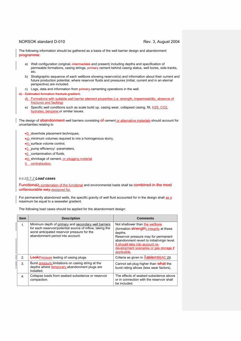
NORSOK standard D-010 Rev. 3, August 2004 The following information should be gathered as a basis of the well barrier design and abandonment programme:
a) Well configuration (original, intermediate and present) including depths and specification of permeable formations, casing strings, primary cement behind casing status, well bores, side-tracks, etc.
b) Stratigraphic sequence of each wellbore showing reservoir(s) and information about their current and future production potential, where reservoir fluids and pressures (initial, current and in an eternal perspective) are included.
c) Logs, data and information from primary cementing operations in the well. d) Estimated formation fracture gradient.
d) Formations with suitable well barrier element properties (i.e. strength, impermeability, absence of fractures and faulting)
e) Specific well conditions such as scale build up, casing wear, collapsed casing, fill, H2S, CO2, hydrates, benzene or similar issues.
The design of abandonment well barriers consisting of cement or alternative materials should account for uncertainties relating to
•f) downhole placement techniques, •g) minimum volumes required to mix a homogenous slurry, •h) surface volume control, •i) pump efficiency/ -parameters, •j) contamination of fluids, •k) shrinkage of cement. or plugging material l) centralisation.
9.6.29.7.2 Load cases
FunctionalA combination of the functional and environmental loads shall be combined in the most unfavourable way.designed for. For permanently abandoned wells, the specific gravity of well fluid accounted for in the design shall as a maximum be equal to a seawater gradient. The following load cases should be applied for the abandonment design: Item Description Comments
1. Minimum depth of primary and secondary well barriers for each reservoir/potential source of inflow, taking the worst anticipated reservoir pressure for the abandonment period into account.
Not shallower than the wellbore (formation strength) integrity at these depths. Reservoir pressure may for permanent abandonment revert to initial/virgin level. It should take into account re-development scenarios or gas storage if applicable.
2. LeakPressure testing of casing plugs. Criteria as given in TableWBEAC 24.
3. Burst pressure limitations on casing string at the depths where temporary abandonment plugs are installed.
Cannot set plug higher than what the burst rating allows (less wear factors).
4. Collapse loads from seabed subsidence or reservoir compaction.
The effects of seabed subsidence above or in connection with the reservoir shall be included.
NORSOK standard D-010 Rev. 3, August 2004 9.6.3 Minimum design factors The design factors shall be as described in 5.6.4 and 7.6.4.
9.79.8 Other topics
9.7.19.8.1 Risks
Risk Design and operational risks shall be assessed relating to . Typical risk could include: a) pressure and wellbore (formation) integrity uncertainties, b) time effects on well barriers such as :
• long term development of reservoirreservoir pressure, possible • deterioration of materials used, • sagging of weight materials in well fluids, etc.
c) HSE risks related to removal and handling of possible scale in production tubing shall
be considered in connection with plugging of development wells.,
d) HSE risk relating to cutting of tubular goods, detecting and releasingH2S or CO2, e) release of trapped pressure and recovery of materials with , f) unknown status shall be assessed.of equipment or materials, g) environmental issues.
9.7.29.8.2 Removing equipment above seabed For permanent abandonment wells, the wellhead and casings shall be removed below the seabed. The cutting depth shall be sufficient to prevent conflict with other marine activities. Local conditions such as soil and seabed scouring due to sea current should be considered. For deepwater wells, it may be acceptable to leave or cover the wellhead/structure. Mechanical or abrasive cutting is the preferred method for removal of the casing/conductor at seabed. Use of explosives to cut casing/conductor is acceptable only if measures are implemented (Example: directed/ shaped charges and providing upward and downward protection) which reduces the risk to surrounding environment to the same level as other means of cutting casing. For permanent abandonment wells, the wellhead and the following casingsThe location shall be removed such that no parts of the well ever will protrude the seabed. Required cutting depth below seabed should be considered in each case, and be based on prevailing local conditions such as soil, sea bed scouring, sea current erosion, etc.. The cutting depth should be 5 m below seabed. Noinspected to ensure no other obstructions related to the drilling and well activities shall beare left behind on the sea floor.

NORSOK standard D-010 Rev. 3, August 2004
9.8 Attachments – Well barrier schematics (WBS)
NORSOK standard D-010 Rev. 3, August 2004
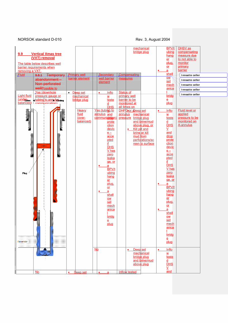
9.9 Vertical Xmas tree (VXT) removal
The table below describes well barrier requirements when removing a VXT. Fluid 9.8.1 Temporary
abandonment – Non-perforated wellPossible to
Primary well barrier element
Secondary well barrier element
Compensating measures
Light fluid (under-balanced)
Yes (downhole pressure gauge or tubing to annulus communication)
• Deep set mechanical bridge plug
• Inflow tested DHSV and drop protection device – accepted if DHSV has zero leakage, or
• a BPV/tubing hanger plug, or
• a shallow set mechanical bridge plug
Status of primary well barrier to be monitored at all times on DHPG or a-annulus pressure
No • Deep set • a Inflow tested
mechanical bridge plug
BPV/tubing hanger plug, or
• a shallow set mechanical bridge plug
DHSV as compensating measure due to not able to monitor primary barrier
Heavy fluid (over-balanced)
Yes (tubing to annulus communication)
• Deep set mechanical bridge plug and brine/mud above plug, or
• Kill pill and brine or kill mud from perforations/screen to surface
• Inflow tested DHSV and drop protection device – accepted if DHSV has zero leakage, or
• a BPV/tubing hanger plug, or
• a shallow set mechanical bridge plug
Fluid level or applied pressure to be monitored on A-annulus
No • Deep set mechanical bridge plug and brine/mud above plug
• Inflow tested DHSV and
Innsatte celler
Innsatte celler
Innsatte celler
Innsatte celler
Innsatte celler
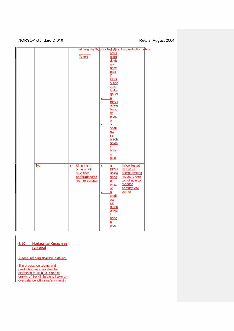
NORSOK standard D-010 Rev. 3, August 2004
drop protection device – accepted if DHSV has zero leakage, or
• a BPV/tubing hanger plug, or
• a shallow set mechanical bridge plug
No • Kill pill and
brine or kill mud from perforations/screen to surface
• a BPV/tubing hanger plug, or
• a shallow set mechanical bridge plug
Inflow tested DHSV as compensating measure due to not able to monitor primary well barrier
9.10 Horizontal Xmas tree removal
A deep set plug shall be installed. The production tubing and production annulus shall be displaced to kill fluid. Specific gravity of the kill fluid shall give an overbalance with a safety margin
at plug depth, prior to pulling the production tubing. When
NORSOK standard D-010 Rev. 3, August 2004
Well barrier elements
See Table Comments
Primary well barrier, last open hole 1. Cement plug 24 Shoe track. 2. Casing (liner) cement 22 3. Casing (reservoir
liner) 2 Un-perforated w/2 each
float valves. or 1. Cement plug 24 Shoe track. 2. Casing cement 22 3. Reservoir casing 2 Un-perforated w/2 each
float valves. Secondary well barrier, temporary abandonment 1. Casing 2 2. Casing cement 22 3. Cement plug or
mechanical plug 24 28
Shallow plug.
or 1. Casing cement 22 2. Casing 2 Intermediate 3. Wellhead 5 4. Casing 2 Production casing. 5. Cement plug or
mechanical plug 24 28
Shallow plug.
Note None
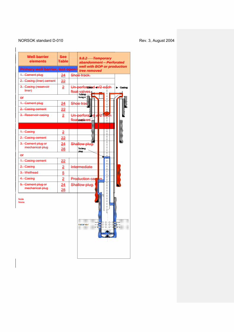
9.8.2 Temporary abandonment – Perforated well with BOP or production tree removed
NORSOK standard D-010 Rev. 3, August 2004
Well barrier elements
See Tabl
e Comments
Primary well barrier
1. Casing (liner) cement 22 2. Casing (liner) 2 Liner above perforations. 3. Liner top packer 43 4. Casing 2 Below production packer. 5. Production packer 7 50 m below TOC in casing
annulus. 6. Completion string 25 7. Deep set tubing plug 6 or, 1. Casing cement 22 2. Casing 2 Above perforations. 3. Production packer 7 4. Completion string 25 5. Deep set tubing plug 6 Secondary well barrier, reservoir 1. Casing cement 22 Above production packer. 2. Casing 2 Common WBE, between
liner top packer and production packer.
3. Wellhead 5 4. Tubing hanger 10 5. Tubing hanger plug 11 For SSWs. 6. Completion string 25 Down to SCSSV. 7. SCSSV 8 or, 1. Casing cement 22 Intermediate casing. 2. Casing 2 Intermediate casing. 3. Wellhead 5 4. Tubing hanger 10 5. Tubing hanger plug 11 For SSWs. 6. Completion string 25 Down to SCSSV. 7. SCSSV 8
Note None
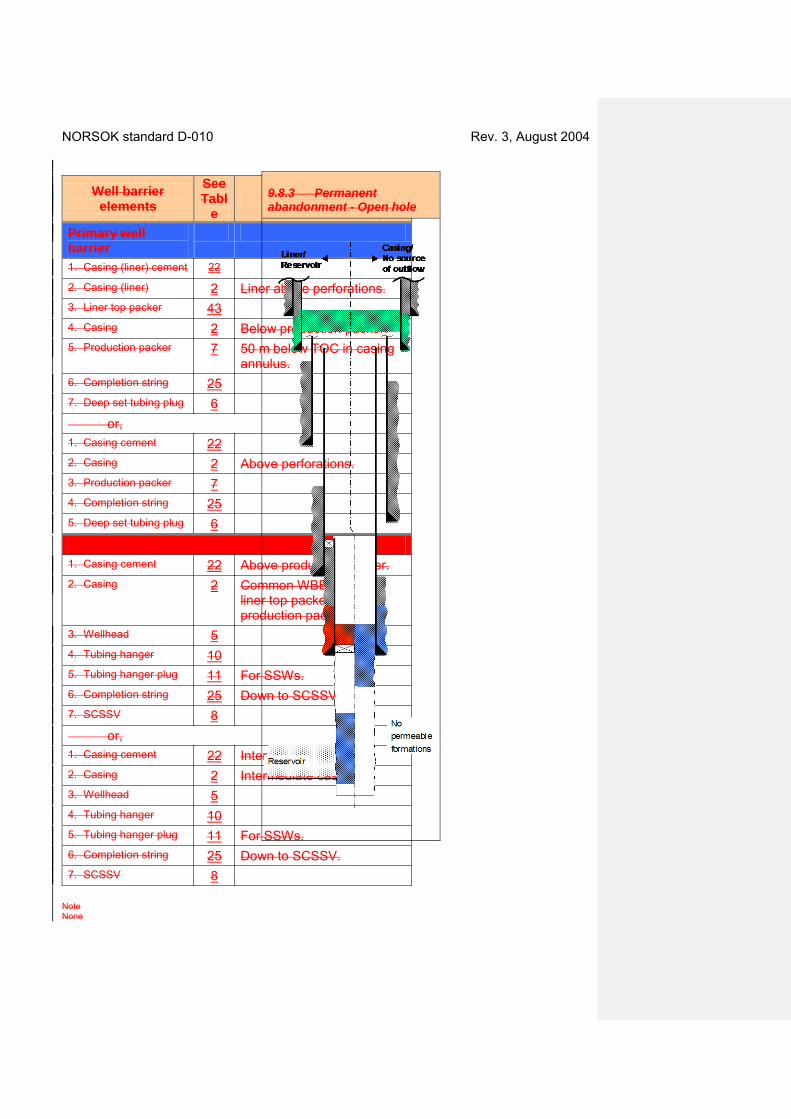
9.8.3 Permanent abandonment - Open hole
NORSOK standard D-010 Rev. 3, August 2004
Well barrier elements
See Table Comments
Primary well barrier
1. Cement plug 24 Open hole.
or, (“primary well barrier, last open hole”):
1. Casing cement 22
2. Cement plug 24 Transition plug across casing shoe.
Secondary well barrier, reservoir 1. Casing cement 22
2. Cement plug 24 Cased hole cement plug installed on top of a mechanical plug.
Open hole to surface well barrier 1. Cement plug 24 Cased hole cement plug.
2. Casing cement 22 Surface casing.
Notes Verification of primary well barrier in the “liner case” to be carried out as detailed in Table 22.the tubing is removed, a shallow plug shall be installed in production casing prior to removal of the XT. a. b. The well barrier in deepest casing shoe can for both cases be designed either way, if casing/liner cement is verified and O.K. c. The secondary well barrier shall as a
minimum be positioned at a depth where the estimated formation fracture pressure exceeds the contained pressure below the well barrier.
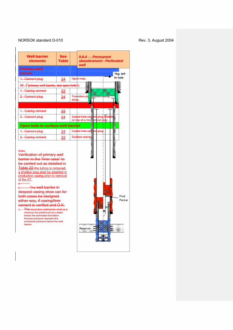
9.8.4 Permanent abandonment - Perforated well
NORSOK standard D-010 Rev. 3, August 2004
Well barrier elements
See Table Comments
Primary well barrier
1. Liner cement 22
2. Cement plug 24 Across and above perforations.
Secondary well barrier, reservoir 1. Casing cement 22
2. Cement plug 24 Across liner top.
or, for tubing left in hole case: 1. Casing cement 22
2. Cement plug 24 Inside and outside of tubing.
Open holes to surface well barrier 1. Cement plug 24
2. Casing cement 22 Surface casing.
Notes 1. Cement plugs inside casing shall be set in areas with verified cement in casing annulus. 2. The secondary well barrier shall as a
minimum be positioned at a depth where the estimated formation fracture pressure exceeds the contained pressure below the well barrier.
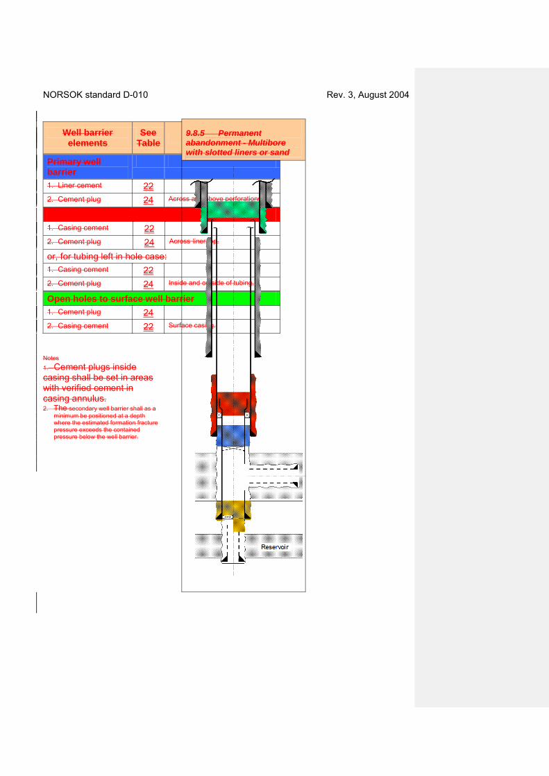
9.8.5 Permanent abandonment - Multibore with slotted liners or sand

NORSOK standard D-010 Rev. 3, August 2004
Well barrier elements
See Table Comments
Barrier between reservoirs 1. Casing cement 22
2. Cement plug 24 Cased hole.
or,
2. Cement plug 24 Transition plug across casing shoe.
Primary well barrier
1. Cement plug 24 Across wellbore and casing shoe.
Secondary well barrier, reservoir 1. Casing cement 22
2. Cement plug 24 Casing plug across liner top.
Open Holes to surface wellbarrier 1. Cement plug 24 Cased hole cement plug.
2. Casing cement 22 Surface casing.
Notes 1. The “well barrier between reservoirs”
may act as the primary well barrier for the “deep” reservoir, and “primary well barrier” may be the secondary well barrier for “deep” reservoir, if the latter is designed to take the differential pressures for both formations.
2. Secondary well barrier shall not be set higher than the formation integrity at this depth, considering that the design criteria may be initial reservoir pressure, as applicable in each case.
9.8.6 Permanent abandonment - Slotted liners in multiple reservoirs
NORSOK standard D-010 Rev. 3, August 2004
Well barrier elements
See Table Comments
Primary well barrier, deep reservoir 1. Cement plug 24 Through liner and across casing
shoe/Open hole transition.
Secondary well barrier 1. Casing cement 22 2. Cement plug 24 Across liner top.
Primary well barrier, shallow reservoir 1. Cement plug 22 Squeezed into perforated casing
annulus above potential reservoir.
Secondary well barrier, shallow reservoir 1. Casing cement 22 2. Cement plug 24 Open holes to surface well barrier 1) Cement plug 24 Cased hole.
2) Casing cement 22 Surface casing.
Notes 1. Secondary well barrier shall not be set
higher than the formation integrity at this depth, considering that the design criteria may be initial reservoir pressure, which may develop over time.
2. The case on the right hand side indicates that the intermediate casing string is cemented into surface casing, i.e. with no open annulus to surface. Hence, no open holes to surface well barrier is required.
9.8.7 Suspension - Hang-off/Disconnect of mariner riser

NORSOK standard D-010 Rev. 3, August 2004
Well barrier elements
See Table Comments
Primary well barrier 1. Fluid column 1 Time limited barrier, see Note 1.
Secondary well barrier
1. Casing cement 22 Last casing.
2. Casing 2 3. Wellhead 5 4. BOP 4
Notes 1. Well bore fluid shall be qualified
through test for the hang-off period. 2. A “storm valve” should be installed in
the drillpipe hang-off assembly

NORSOK Standard D-010 Rev. 4, August 2012
NORSOK standard


 XXX draft ANNEXES 1 to 22 · 2020. 11. 4. · competence including networking (industrial research, experimental development, feasibility studies) 010 Digitizing](https://static.fdocuments.us/doc/165x107/609dd44586411469472e3a2c/brussels-xxx-2018-xxx-draft-annexes-1-to-22-2020-11-4-competence-including.jpg)