Table of Contents - Logos · PDF fileTable of Contents About ... as an x-ray image enhancer...
48
Transcript of Table of Contents - Logos · PDF fileTable of Contents About ... as an x-ray image enhancer...


Logos Imaging Application User’s Manual Version 6.0.1 Page 1
Table of Contents About ......................................................................................................................................................................... 4
System Requirements ................................................................................................................................................ 5
Uninstall Previous Versions ....................................................................................................................................... 5
Install LIA 6.0 ............................................................................................................................................................. 6
Install the Device Drivers ......................................................................................................................................... 13
Register .................................................................................................................................................................... 14
Getting Help............................................................................................................................................................. 14
Technical Support .................................................................................................................................................... 14
Workspace Layout ................................................................................................................................................... 15
Customize the Workspace ................................................................................................................................... 16
Image Correction Pane ........................................................................................................................................ 17
Levels Panel ......................................................................................................................................................... 18
Filters Panel ......................................................................................................................................................... 19
Percept Panel ....................................................................................................................................................... 19
Pan Control Panel ................................................................................................................................................ 19
Image Details Panel ............................................................................................................................................. 20
Incident Manager Pane ....................................................................................................................................... 21
Tools Palette ........................................................................................................................................................ 22
Options Bar .......................................................................................................................................................... 23
Menu Bar ............................................................................................................................................................. 24
File Menu ............................................................................................................................................................. 24
Edit Menu ............................................................................................................................................................ 25
Tools Menu .......................................................................................................................................................... 25
Image Menu ......................................................................................................................................................... 26
View Menu .......................................................................................................................................................... 27
Help Menu ........................................................................................................................................................... 27
Preferences .............................................................................................................................................................. 28
Working with Incidents ........................................................................................................................................... 29
Incident File Location .......................................................................................................................................... 29

Logos Imaging Application User’s Manual Version 6.0.1 Page 2
Create an Incident ............................................................................................................................................... 31
Open an Incident ................................................................................................................................................. 31
Search for Incidents ............................................................................................................................................. 32
Edit Incident Information .................................................................................................................................... 32
Move an Incident ................................................................................................................................................. 33
Delete Incidents ................................................................................................................................................... 33
Working with Images ............................................................................................................................................... 34
Add a Logos Image ............................................................................................................................................... 34
Delete an Image ................................................................................................................................................... 34
Export an Image ................................................................................................................................................... 35
Import a New Image ............................................................................................................................................ 36
E-mail Image ........................................................................................................................................................ 36
Image Properties ................................................................................................................................................. 36
Export Image Script ............................................................................................................................................. 37
Open and Save an Image ..................................................................................................................................... 37
Save Selection to Folder ...................................................................................................................................... 38
Editing Images ......................................................................................................................................................... 39
Adjustments ........................................................................................................................................................ 40
Levels ................................................................................................................................................................... 40
Filters ................................................................................................................................................................... 41
Percept ................................................................................................................................................................ 41
Apply Image ProcessingScript.............................................................................................................................. 42
Annotations ......................................................................................................................................................... 42
Stitch Images ....................................................................................................................................................... 44
Print an Image ..................................................................................................................................................... 45
Region of Interest ................................................................................................................................................ 45
Recover and Undo ............................................................................................................................................... 45
View Images ............................................................................................................................................................. 46
Zoom .................................................................................................................................................................... 46
Pan Control .......................................................................................................................................................... 46
Rotate Images ...................................................................................................................................................... 46
Magnify Tool ........................................................................................................................................................ 47

Logos Imaging Application User’s Manual Version 6.0.1 Page 3
Grid and Annotations .......................................................................................................................................... 47

Logos Imaging Application User’s Manual Version 6.0.1 Page 4
About Version 6.0 of the Logos Imaging Application (LIA) is a proprietary Image Management system designed using the Windows Presentation Foundation (WPF). In conjunction with the Logos Scanner, LIA is used to create and maintain incidents storing radiographic images. Incidents consist of event specific information (technicians name, incident location and address, and notes) along with a series of scanned x-ray images. In addition to incident management capabilities, the application also functions as an x-ray image enhancer with image processing filters and annotation capabilities. Within this software application, you can create and maintain incidents to store radiographic records. Once you have created an incident, you can use a wide variety of TWAIN compatible devices to add, edit, and annotate the images.

Logos Imaging Application User’s Manual Version 6.0.1 Page 5
System Requirements The Logos Imaging Software Application will run on computers with the following specifications:
• Operating System: Windows XP, Windows Vista, or Windows 7
• USB 2.0 port
• Minimum 2.0 GHz processor
• 1GB of RAM (2GB recommended)
• Display: Minimum 1024 x 780 resolution
• Hard drive with at least 80 dedicated gigabytes
• CD drive
Uninstall Previous Versions Note: If you are upgrading the Logos Imaging Application, please uninstall your old version prior to installing Version 6.0.
1. Go to Start/Control Panel/Add or Remove Programs, select Logos Imaging Application, and click Change/Remove.
2. In the InstallShield Wizard window, select Remove and click Next.
3. Confirm File Deletion by clicking OK. The system WILL NOT delete your existing image files.
4. Click Yes when prompted to delete all old or shared files.
5. Click Finish.
You are now ready to continue Installing the Logos Imaging Software Application.
Logos Imaging Application User’s Manual Version 6.0.1 Page 6
Install LIA 6.0 IMPORTANT: Prior to Installing the Logos Imaging Application Version 6.0, please connect to Windows Update and install all priority updates for your computer.
Note: If you are reinstalling the Logos Imaging Software Application, please uninstall your old version prior to installing the updated software.
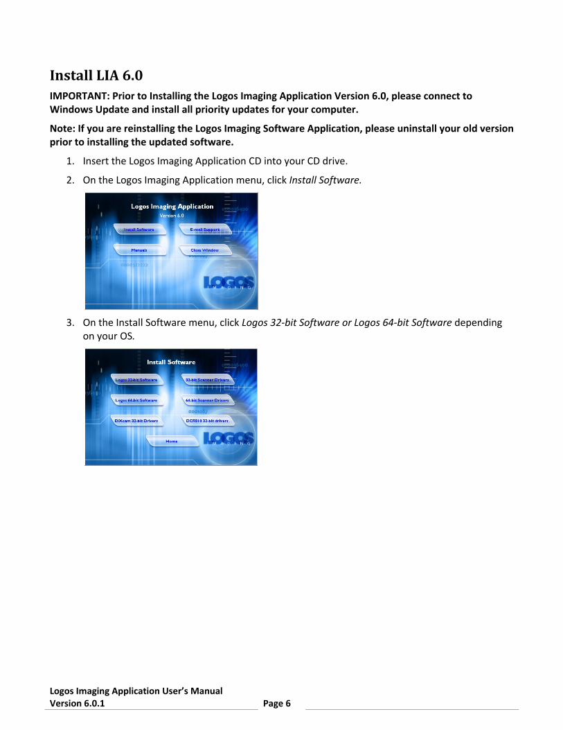
1. Insert the Logos Imaging Application CD into your CD drive.
2. On the Logos Imaging Application menu, click Install Software.
3. On the Install Software menu, click Logos 32-bit Software or Logos 64-bit Software depending
on your OS.

Logos Imaging Application User’s Manual Version 6.0.1 Page 7
4. There may be a considerable delay as the installer checks your system for the required prerequisites. If .NET Framework 3.5 SP1 or Microsoft Visual C++ 2008 Redistributable are missing, the installer will open the Welcome to the Prerequisites Wizard. If there are no missing components, the installer will move to step 13.
5. Read the License agreement, and select I accept the terms in the license agreement and click
Next.
6. Ensure each missing component is checked and click Next to begin installation.

Logos Imaging Application User’s Manual Version 6.0.1 Page 8
7. If .NET Framework 3.5 SP1 is required, read the License agreement, select I have read and ACCEPT the terms of the License Agreement, and click Install.
8. In the Microsoft .NET Framework 3.5 SP1 Setup window, click Exit.
9. If Microsoft Visual C++ 2008 Redistributable is required, click Next in the Setup window.

Logos Imaging Application User’s Manual Version 6.0.1 Page 9
10. Read the License agreement, select I have read and accept the license terms, and click Install.
11. In the Microsoft Visual C++ 2008 Redistributable Setup window, click Finish.
12. When the .NET Framework 3.5 SP1 and Microsoft Visual C++ 2008 Redistributable installations
are complete, you may be prompted to restart your computer. Allow the computer to restart. If the Logos Installer does not begin automatically after the computer restarts, browse to the Logos CD root directory, launch LIA.exe, click Install Software, and click Logos Software.
13. In the Welcome Logos Imaging Application 6.0 Setup window, click Next.

Logos Imaging Application User’s Manual Version 6.0.1 Page 10
14. Read the License agreement, select I accept the terms in the license agreement, and click Next.
15. Click Next to keep the default destination location.
16. Click Install to begin installation.
17. Click OK in the CRystalView T-Series Driver Installation Wizard window. If you have previously
installed CRystalView drivers, the software will skip to step 26.

Logos Imaging Application User’s Manual Version 6.0.1 Page 11
18. Click Next in the CRystalView T-Series Driver Installation Wizard window.
19. Click Install in the CRystalView T-Series Driver Installation Wizard window.
20. Click Next in the Device Driver Installation Wizard window.

Logos Imaging Application User’s Manual Version 6.0.1 Page 12
21. Click Finish in the Device Driver Installation Wizard window.
22. Repeat steps 20-21 for each Device Driver
23. Click OK in the RegSvr32 window.
24. Click Finish in the CRystalView T-Series Driver Installation Wizard window.
25. Click OK in the CRystalView T-Series Driver Installation Wizard window. Wait until after step 26
to connect the scanner.
26. Click Finish in the Completing the Logos Imaging Application 6.0 Setup window.
27. You will require the registration key, which is printed on the software CD, the first time you launch the application. If your computer is not connected to the internet, you will require access to a computer with internet access to activate your software.

Logos Imaging Application User’s Manual Version 6.0.1 Page 13
Install the Device Drivers Note: If you are installing the software on computer that has not been previously used with the Logos scanner, you must install the driver files separately on each USB port intended for use with the Logos Scanner. To install drivers on additional USB ports, turn the scanner power off, disconnect the USB cable, and complete steps 1 – 11 on each USB port.
1. Attach a USB cable to the back of the Logos Scanner and then to an open USB port on your computer.
2. Plug the power cable into the Logos scanner and then into an 110V or 220V power supply.
3. Power On the scanner.
4. Steps 5 – 11 apply to XP only. In Vista and Windows 7, the drivers will install automatically.
5. In the T-Series Combo Firmware New Hardware Wizard window, select No, not this time when asked if Windows can connect to Windows Update to search for software. Click Next
6. Select Install the software automatically (Recommended). Click Next
7. In the Completing the Found New Hardware Wizard window, click Finish.
8. In the T100 Scanner New Hardware Wizard window, select No, not this time when asked if Windows can connect to Windows Update to search for software. Click Next
9. Select Install the software automatically. Click Next.
10. Click Continue Anyway in the Windows Logo testing notification window.
11. In the Completing the Found New Hardware Wizard window, click Finish.

Logos Imaging Application User’s Manual Version 6.0.1 Page 14
Register Register your product to receive no charge product support and update notifications.
To register, please visit www.logosimaging.com/registration.html.
Getting Help You can get Help anytime when using Logos Imaging Software Application. You can:
• Press F1 or click the Help button in any dialog box for specific information on that dialog box.
• Click Help Topics on the Help menu to open the table of contents for the Help system.
Once a Help topic is open, you can use the table of contents, search for a particular word of phrase, or use the index to navigate to a different topic.
Technical Support Please call (866) 939-4044 for technical support. If you are calling between the hours of 5:00 pm and 8:00 am Eastern, please select option one to be connected to an after-hours support representative

Logos Imaging Application User’s Manual Version 6.0.1 Page 15
Workspace Layout
The LIA workspace includes:
• The Menu bar across the top organizes commands under the File, Edit, Tools, Image, View, and Help menus.
• The Tools palette contains tools for annotating, measuring, calibrating, and transforming an image.
• The Options bar displays options for the currently selected tool.
• The Image pane displays the image(s) you are editing.
• The Incident Manager pane displays the incident details and image thumbnails for the selected incident.
• The Image Correction pane displays the Levels panel, the Filters panel, the Percept Contrast panel, and the Pan Control panel.

Logos Imaging Application User’s Manual Version 6.0.1 Page 16
Customize the Workspace The default workspace displays all panes available in the Logos Imaging Application. You can hide panes by selecting the pane name on the View menu.
You can also change the behavior of the Incident Manager and Image Correction panes to auto hide when not in use. Setting these panes to auto hide allows more real estate for image display.
To use the Incident Manager and Image Correction panes in auto hide mode:
1. Click the Minimize icon on the top right of the pane.
2. The pane will retract to a named tab.
3. Mouse over the tab to display the hidden pane.
4. Move the mouse over the pane to keep the pane visible.
5. When you are finished working in the pane, move the mouse out of the pane. The pane will retract. If you have clicked in the pane, it will not retract until you click in another pane.
6. To reset the pane to be viewed at all times, click the Pin icon on the top right of the pane.
You can also set the Incident Manager to be viewed as a tabbed document in the Image pane.
To use the Incident Manager in tabbed document view (helpful for low resolution displays):
1. Click the Tabbed Document icon on the top right of the pane.
2. The Incident Manager will appear in the Image pane.
3. Double clicking an image thumbnail in the Incident Manager will open the image in new tabbed document. You can switch back to the Incident Manager by clicking the Incident Manager tab in the Image pane.
4. To return the Incident Manager to its default location, click the Dock icon on the top right of the Image pane.

Logos Imaging Application User’s Manual Version 6.0.1 Page 17
Image Correction Pane The Image Correction pane displays the Levels, Filters, and Pan Control panels. To maximize screen real estate, the most common functions in the panels are visible, while less commonly used functions are hidden. Click the More icon at the bottom of the panels to view all available functions.
You can set the Image Correction pane to hide or auto hide.
To hide/unhide the Image Correction pane:
1. Click the Close icon on the top right of the pane to hide the Image Correction pane.
2. Click the Image Correction command on the View menu to unhide the Image Correction pane and restore it to the default location.
To use the Image Correction pane in auto hide mode:
1. Click the Minimize icon on the top right of the pane.
2. The pane will retract to a named tab.
3. Mouse over the tab to display the hidden pane.
4. Move the mouse over the pane to keep the pane visible.
5. When you are finished working in the pane, move the mouse out of the pane. The pane will retract. If you have clicked in the pane, it will not retract until you click in another pane.
6. To reset the pane to be viewed at all times, click the Pin icon on the top right of the pane.

Logos Imaging Application User’s Manual Version 6.0.1 Page 18
Levels Panel The Levels panel allows you to adjust the active image to increase visible contrast. By default, the Brightness, Contrast, and Gamma controls are hidden. Click the More icon at the bottom of the Levels panel to view all controls.
• Histogram - Displays the brightness levels of the image and lets you use a slider to adjust them.
Expanded View - Opens a large histogram map to allow more precise adjustment.
Reset - Resets histogram sliders to original settings.
Auto - Performs an image normalization process.
• Brightness, Contrast, and Gamma - Adjusts the brightness, contrast, and gamma (the shadow and highlight tones) of the image.
Reset - Resets brightness, contrast, and gamma sliders to original settings.

Logos Imaging Application User’s Manual Version 6.0.1 Page 19
Filters Panel The Filters panel shows preview thumbnails for the image processing filters. By default, less commonly used filters are hidden. Click the More icon at the bottom of the Filters panel to view all filters.
• Equalize - Equalizes the brightness of the image.
• Invert - Reverses the image's colors. For example, black becomes white, red becomes green, etc.
• Emboss - Accentuates the high-contrast edges and flattens the low-contrast areas, making a relief-map type image.
• Original - Removes all applied filters and resets levels to the settings of the saved image. Original does not undo rotations.
• Outline - Changes the image so the edges of the image are outlined with dark lines against a light background.
• Smooth - Makes the image's edges less sharp.
• Sharpen - Makes the image's edges appear more sharply defined.
• Despeckle - Removes noise from images without blurring edges
• Colorize - Colors the entire image.
Percept Panel The Percept Panel includes an adjustable slider and four presets (1, 5, 10, and 20) to set the level of contrast enhancement.
Pan Control Panel The Pan Control panel allows you to adjust the current view of your image by zooming in or zooming out on a specific area of the image. The colored box in the Pan Control thumbnail display corresponds to the viewable area in the Image pane.

Logos Imaging Application User’s Manual Version 6.0.1 Page 20
Image Details Panel The Image Details panel displays information for the active image. Click the More icon at the bottom of the Image Details panel to view all details.
• Cursor Position - Displays the X and Y coordinates of the current cursor position.
• Pixel Value - Displays the grayscale or color value of the pixel at the current cursor position.
• X-Ray Exposure - Displays a value indicating the accumulated x-ray dose. (Available only with the T210 and R200 scanners.)
o Correct Exposure
Speed Class 50 = 4 mR
Speed Class 100 = 2 mR
Speed Class 200 = 1 mR
Speed Class 400 = 0.5 mR
Speed Class 800 = 0.25 mR
o Exposure Value Indicator (EIV)
2,000 represents the correct exposure
1,700 represents ½ of the correct exposure
2,300 represents two times the correct exposure
• Width and Height - Displays the dimensions of the image in pixels.
• Created Date - Displays the date and time the image was created.
• Pixel Format - Displays the image format.
• Image Processing History - Displays a list of filters and adjustments applied to the active image. You can turn individual filters and adjustments on and off by checking and unchecking their associated checkbox.
• Export Image Script - Saves the history of filters and adjustments applied to an image to a script that you can apply to other images using the Apply Image Processing Script command on the Image menu.

Logos Imaging Application User’s Manual Version 6.0.1 Page 21
Incident Manager Pane The Incident Manager pane displays a list of existing incidents and the associated image thumbnails. From this pane you can open existing incidents, create new incidents, delete old incidents, and view or edit its associated images.
You can set the Incident Manager pane to hide, auto hide, or to be viewed as a tabbed document.
To hide/unhide the Incident Manager pane:
1. Click the Close icon on the top right of the pane to hide the Incident Manager pane.
2. Click the Incident Manager command on the View menu to unhide the Incident Manager pane and restore it to the default location.
To use the Incident Manager pane in auto hide mode:
1. Click the Minimize icon on the top right of the pane.
2. The pane will retract to a named tab.
3. Mouse over the tab to display the hidden pane.
4. Move the mouse over the pane to keep the pane visible.
5. When you are finished working in the pane, move the mouse out of the pane. The pane will retract. If you have clicked in the pane, it will not retract until you click in another pane.
6. To reset the pane to be viewed at all times, click the Pin icon on the top right of the pane.
To use the Incident Manager in tabbed document view (helpful for low resolution displays):
1. Click the Tabbed Document icon on the top right of the pane.
2. The Incident Manager will appear in the Image pane.
3. Double clicking an image thumbnail in the Incident Manager will open the image in new tabbed document. You can switch back to the Incident Manager by clicking the Incident Manager tab in the Image pane.
4. To return the Incident Manager to its default location, click the Dock icon on the top right of the Image pane.

Logos Imaging Application User’s Manual Version 6.0.1 Page 22
Tools Palette The Tools palette contains tools for annotating, measuring, calibrating, and transforming an image.
• Auto Adjust - Applies predefined filters, including Invert, to allow users a quick option for image enhancement.
• Select - Switches to the cursor mode so that you can select an annotation to change or delete. For example, select an existing rectangular annotation and then drag on any corner or line midsection to change the size. Click any other part of the outline to move it.
• Line - Draws a line from one point to the other. To draw a line, select the line tool, move the cursor to the starting point of the line, click and hold the left mouse button, drag the cursor to the ending point of the line, and release the left mouse button.
• Polyline - Draws a line between points. To draw a polyline, click the start point, click the next point, click the next point, and so on. Double click the final point to close the draw polyline function.
• Rectangle - Draws a rectangle. To draw a rectangle, select the rectangle tool, move the cursor to the starting point of the rectangle, click and hold the left mouse button, drag the cursor to the ending point of the rectangle, and release the left mouse button.
• Ellipse - Works the same as Rectangle, but draws a circular or oval figure.
• Text - Adds text to the image. To add text to the image, select the text tool, choose font attributes for the text from the toolbar, move the cursor to the starting point of the text box, click and hold the left mouse button, drag the cursor to the ending point of the text box, release the left mouse button, type the text, and click outside of the text box to complete the entry.
• Measure - Measures the straight-line length or angle of a previously drawn annotation. After an annotation is drawn, choose the Measure tool and then select the annotation by clicking on an annotation line to obtain a straight-line measurement. Obtain an angle clicking the vertex of an angle created with the polyline tool.
• Calibration - Adjusts the image resolution to account for geometric magnification in radiographic images. To calibrate an image based upon the size of a known object, select the calibration tool, draw a line along the length of a known object (do not select the line tool), enter the actual length of the line, and click Close.
• Magnify - Works as a floating magnifying glass to zoom in on a specific area of the image. To zoom in on a specific area, select the magnify tool, choose the magnification factor and filter for the tool in the drop down menus, hold the left mouse button with the cursor over the Magnify tool, and move your mouse over areas of interest to magnify that area.

Logos Imaging Application User’s Manual Version 6.0.1 Page 23
Options Bar
Annotations - The Options bar displays annotation attributes when you click any shape or line on the Tools menu or on the Tools palette.
• Line Color: Choose the color of the line or shape outline.
• Fill Color: Choose No Fill or select a color to fill in the shape's area.
• Line Width: Select the pixel size of the line or shape outline.
• Start Arrow: For lines, toggle a starting arrow head on or off.
• End Arrow: For lines, toggle an ending arrow head on or off.
• Measure: For lines, automatically adds a measurement as the line is drawn.
• Line Profile: For lines, automatically adds a line profile as the line is drawn.
• Measurement Units: For lines, overrides the application defaults defined in the preferences dialog when adding measuurements as a line is drawn.
Text - The Options bar displays text attributes when you click the Text command on the Tools menu or on the Tools palette.
• Text Color: Select a color for the text.
• Fill Color: Select a color for the text box background.
• Font: Choose a font style for the text.
• Font Size: Choose a font size for the text.
• B I U: Choose any combination of Bold, Italic, and Underline.
Region of Interest - The Options bar displays region options when you click the Select Region command on the Tools menu or on the Tools palette.
• Crop: Crops the image to the selected area.
• Reset: Clears the selected area.

Logos Imaging Application User’s Manual Version 6.0.1 Page 24
Menu Bar The Menu bar across the top of the application window organizes commands under the following menus.
• File Menu
• Edit Menu
• Tools Menu
• Image Menu
• View Menu
• Help Menu
File Menu New
• New Incident Location - Opens the Incident Location dialog to add another incident file location to view, import, or export incidents from another storage device.
• New Incident - Sets the Incident Manager to New Incident mode to create a new incident in the active Incident File Location.
• New Stitch Image - Opens a new image document to combine multiple images.
Database
• Create Backup - Opens a dialog to create backups of selected incident file locations.
• Restore from Backup - Opens dialog to restore incident file locations from previous backups.
Open - Opens the image selected in the Incident Manage pane for editing.
Close - Closes the active image.
Save - Saves the active image using the current file name. Save is not available with scanned or imported images.
Save As - saves the active image to a user defined xml file.
Save Selection to Folder - Saves the region of interest selection to the folder defined in the system preferences on the Edit menu.
Import
• Image - Opens the Import Image dialog to copy image(s) to active incident.
• Incident - Opens the Import/Export to dialog to move incidents from one database location to another.

Logos Imaging Application User’s Manual Version 6.0.1 Page 25
Export
• Image - Opens the Export Image dialog to copy the selected image(s) to another folder.
• Incident - Opens the Import/Export to dialog to move incidents from one database location to another.
Print - Prints the active image.
Exit - Close the Logos Imaging Application.
Edit Menu Undo - Removes recently performed operations one step at a time.
Redo - Reapplies recently performed undo operations one step at a time.
Delete - Deletes the currently selected annotation.
Cut - Cuts the currently selected annotation.
Copy - Copies the currently selected annotation.
Paste - Pastes the most recently cut or copied annotation.
Preferences - Sets preferences for the display language, for the default measuring units (inches or cm), for the grid settings, for Auto Leveling images upon opening them for editing, for the default scanner associated with the Logos Image button, and for the default folder for capturing regions of interest.
Tools Menu Select - Switches to the cursor mode so that you can select an annotation to change or delete.
Line - Draws a line from one point to the other.
Polyline - Draws a line between points.
Rectangle - Draws a rectangle.
Ellipse - Works the same as Rectangle, but draws a circular or oval figure.
Text - Adds text to the image.
Measure - Measures the straight-line length or angle of a previously drawn annotation.
Calibration - Adjusts the image resolution to account for geometric magnification in radiographic images.
Region of Interest - Defines a section of the image for localized processing or for cropping.
Magnify - Works as a floating magnifying glass to zoom in on a specific area of the image.

Logos Imaging Application User’s Manual Version 6.0.1 Page 26
Image Menu Line Profile - Creates a histogram profile of the selected line.
Adjustments
• Original - Removes all filters and resets level adjustments to the settings of the saved image. Original does not undo rotate transformations.
• Auto Correct - Applies predefined filters, including Invert, to allow users a quick option for image enhancement.
• Auto Level - Stretches the image histogram to the full dynamic range of the image format. Image normalization, or contrast stretching, is used to enhance contrast in an image.
• Adaptive Equalization - Performs a contrast limited adaptive histogram equalization on an image to increase contrast.
• Percept Contrast - Adapts the levels of gray in Logos images to be better perceived by human eyesight.
1 - Applies Percept contrast with a setting of 1.
5 - Applies Percept contrast with a setting of 5.
10 - Applies Percept contrast with a setting of 10.
20 - Applies Percept contrast with a setting of 20.
Filters
• Equalize - Equalizes the brightness of the image.
• Invert - Reverses the image's colors. For example, black becomes white, red becomes green, etc.
• Emboss - Accentuates the high-contrast edges and flattens the low-contrast areas, making a relief-map type image.
• Outline - Changes the image so the edges of the image are outlined with dark lines against a light background.
• Smooth - Makes the image's edges less sharp.
• Sharpen - Makes the image's edges appear more sharply defined.
• Despeckle - removes noise from images without blurring edges
• Colorize - Colors the entire image.

Logos Imaging Application User’s Manual Version 6.0.1 Page 27
Rotate
• 90 CW - Rotates the image 90 degrees right
• 90 CCW - Rotates the image 90 degrees left
• 180 - Rotates the image 180 degrees
• Flip Horizontal - Turns the image 180 degrees around a vertical axis. This command is useful if image plates were loaded in the plate holder backwards.
• Flip Vertical - Turns the image 180 degrees around a horizontal axis.
Crop - Crops an image to the selected area.
New Stitch Image - Opens a new image document to combine multiple images.
Apply Image Processing Script - Applies a stored sequence of image processing tools to the active image.
View Menu Zoom In - Zooms in on the active image.
Zoom Out - Zooms out on the active image.
Fit to Window - Zooms the active image to the Image pane so you can see the entire image.
Show Grid - Toggles the visibility of the grid overlay.
Show Markup - Toggles the visibility of all annotations.
Incident Manager - Hides or unhides the Incident Manager pane.
Image Correction - Hides or unhides the Image Correction pane.
Help Menu About - Displays the version of the Logos Imaging Application you are using.
Help - Displays the Help file.

Logos Imaging Application User’s Manual Version 6.0.1 Page 28
Preferences You can set preferences for the grid settings, for Auto Leveling images upon opening them for editing, for the default scanner associated with the Logos Image button, and for the default folder for capturing regions of interest.
To set preferences:
On the File menu, click Preferences.
To set the LIA Language
1. Select the language by using the drop down menu.
To set the LIA Default Measurement Units
1. Select inches or cm to be used for all measurements (you can override this setting for individual measurements using the Measurement Units selection in the Options Bar).
To set the Grid options:
1. Select the grid color by using the grid color drop down menu.
2. Select the grid spacing by using the grid interval drop down menu.
Note: The grid visibility is set on the View menu.
To set the Auto Leveling options:
1. Click the Auto Level Logos Images check box to activate automatic image correction at the time of opening an image for editing.
To set the Default Scanner associated with the Logos Image button:
1. Select the scanner type you are using from the Default Scanner drop down list.
2. The Logos Image button in the Incident Manager window will use the default device for image acquisition. To use another scanning device, use the Import button.
To set the Capture Export Path for images exported by the Save Selection to Folder command:
1. Browse to the folder where you want your image captures stored. You can also create a new folder by using the Make New Folder option.
2. All images captured using the Save Selection to Folder command on the File menu will be saved to this folder using the date and time of the capture as their file name.

Logos Imaging Application User’s Manual Version 6.0.1 Page 29
Working with Incidents The Incident Manager is the pane where you view existing incidents, create new incidents, and delete old incidents.
From this pane, you can also open a specific incident to view or edit its associated images.
Incident File Location Create a new incident file location when you want to view, import, or export incidents from another storage device.
To add incident file locations:
1. On the right side of the top menu bar, click Add Location or choose New Incident Location on the File > New menu.
2. In the Incident Location dialog box, type in a name that identifies the incident database.
3. Click the Browse button to choose the location of the new incident file location. You can also create a new folder by using the Make New Folder option.
4. Click OK in the Browse for Folder Window.
5. Click OK in the Incident Location dialog box.

Logos Imaging Application User’s Manual Version 6.0.1 Page 30
To remove incident file locations:
1. On the right side of the top menu bar, select the incident file location you wish to remove.
2. Click Remove Location.
3. Click OK.
4. The incident file location will no longer be available in the Incident Manager, but the images associated with the incident will not be removed.
To create a backup:
1. On the right side of the top menu bar, click Create Backup or choose Create Backup on the File > Database menu.
2. Select the incident file location you wish to backup.
3. Select a backup location. Note: Logos recommends using the default backup location.
4. Click Save. The backup file name includes the incident file location name and the date and time the backup was created (Incident File Location Name_Day_Month_Year_Hour_Minute).
To restore from a previous backup:
1. On the right side of the top menu bar, click Restore from Backup or choose Restore from Backup on the File > Database menu.
2. Select the backup file to restore. The backup file name includes the incident file location name and the date and time the backup was created (Incident File Location Name_Day_Month_Year_Hour_Minute).
3. Click Open.
4. Select the location to restore the data. Note: The default is the location specified in the backup file.
5. If there is already a database at the specified restore location, the software will prompt you to create a backup of the existing database prior to restoring the old database. Click Yes to create a secondary backup, click No to continue restoring without creating a secondary backup, or click Cancel to stop the restore process.

Logos Imaging Application User’s Manual Version 6.0.1 Page 31
Create an Incident Create a new incident when you need to keep a record of one or more associated images.
To create a new incident:
1. Select the appropriate incident database from the Incident File Location drop-down list on the right side of the top menu bar. You must choose a single database, rather than All Incident Locations.
2. Click New in the Incident Manager pane or choose New Incident on the File > New menu.
3. Provide a unique name for the incident, and fill in information about the scanning technician, the location where the incident occurred, and other useful notes. Important: The text you provide here can be useful when searching for specific incidents, so use pertinent information. You can edit the information at any time.
4. Click OK.
5. The new incident's name appears in the alphabetized list on the left side of the Incident Manager.
Open an Incident Use the Incident Manager to locate and open an existing incident. When an incident is open, you can view, add to, delete, and edit images.
To open an existing incident:
1. Select the appropriate incident database from the Incident File Location drop-down list on the right side of the top menu bar or select All Incident Locations.
2. In the Incident Manager pane, select the name of the incident you want to open from the Incident Manager drop-down list; you can search for it if necessary.

Logos Imaging Application User’s Manual Version 6.0.1 Page 32
Search for Incidents If you want to find a specific incident, you can search for it in the Incident Manager. Search for any of the text previously entered, such as the technician's name, or any other identifying information.
To search for an incident:
1. Select the appropriate incident database from the Incident File Location drop-down list on the right side of the top menu bar or select All Incident Locations.
2. In the Incident Manager pane, click Find.
3. Enter the text for which you want to search in the Search Incident window. For example, if you want to find all incidents from Gate 22, type Gate 22 in the Location field. You can enter text in any or all of the fields to help identify the specific incident(s) you want to find. The search is not case sensitive, so you do not need to worry about the exact capitalization of the words.
4. Click Search.
The incident drop down list shows you all incidents that contain the identifying text you entered. To clear the search results, click Clear.
Edit Incident Information You can edit the identifying text for an incident at anytime.
To edit incident information:
1. Select the appropriate incident database from the Incident File Location drop-down list on the right side of the top menu bar or select All Incident Locations.
2. In the Incident Manager pane, select the name of the incident you want to edit from the Incident Manager drop-down list; you can search for it if necessary.
3. Click Details to view the identifying text for the incident.
4. Add to or change any of the information in the right side of the window.
5. Click Save.

Logos Imaging Application User’s Manual Version 6.0.1 Page 33
Move an Incident You can import or export an incident to another database, if necessary. For example, if the hard disk space on the current system is limited, you might want to move some incidents to a different disk location. You can also use this method to create backup databases.
To import or export an incident:
1. In the Incident Manager pane, click the Import/Export button or choose Import or Export from the File menu.
2. In the From list, select the incident file location containing the incident or incidents you want to export.
3. Under Incidents, select the name of the incidents you want to export. You can select multiple incidents by holding down the Ctrl key as you make selections, or you can select all incidents by checking the All Incidents option.
4. In the To list, select the incident file location where you want to import the incident or incidents.
5. Click Import.
6. A dialog will appear indicating that the incidents have been successfully copied.
Note: Individual images can be exported by using the Export tool in the Incident Browser window.
Delete Incidents If you no longer need an incident, you can permanently remove it from the database. Please note that this will also delete all images in the incident folder.
To delete an incident:
1. Select the appropriate incident database from the Incident File Location drop-down list on the right side of the top menu bar or select All Incident Locations.
2. In the Incident Manager pane, select the name of the incident you want to delete from the Incident Manager drop-down list; you can search for it if necessary.
3. Click Delete Incident.
4. Click Yes to verify that you want to permanently delete the incident and all associated images; otherwise, click No.

Logos Imaging Application User’s Manual Version 6.0.1 Page 34
Working with Images
Add a Logos Image You can add a Logos image from the default scanner to an incident. (You can set the default scanner on the Edit > Preferences menu.)
To add a Logos image:
1. Select the appropriate incident database from the Incident File Location drop-down list on the right side of the top menu bar or select All Incident Locations.
2. In the Incident Manager pane, create an Incident, or select the name of the incident you want to open from the Incident Manager drop-down list.
3. Click Logos Image.
4. Follow the scanner instructions to capture a radiographic image.
Delete an Image If the incident contains images that are no longer useful, you can delete them.
To delete an incident image:
1. Select the appropriate incident database from the Incident File Location drop-down list on the right side of the top menu bar or select All Incident Locations.
2. In the Incident Manager pane, select the name of the incident you want to open from the Incident Manager drop-down list.
3. Select one or more image thumbnails. Use CTRL-click to select additional images; use SHIFT-click to select a range of images or right-click on the image and select Delete.
4. Click Yes to verify that you want to permanently delete the incident images; otherwise, click No.

Logos Imaging Application User’s Manual Version 6.0.1 Page 35
Export an Image You can export (copy) one or more images from the database to a disk location.
To export an image:
1. Select the appropriate incident database from the Incident File Location drop-down list on the right side of the top menu bar or select All Incident Locations.
2. In the Incident Manager pane, select the name of the incident you want to open from the Incident Manager drop-down list.
3. Select one or more image thumbnails and click the Export button or right-click on the image and select Export. (Use CTRL-click to select additional images; use SHIFT-click to select a range of images.)
4. To export annotations with the image, check the Add annotations to image checkbox.
5. Select the output file format in the File format drop down menu.
6. Select the folder where you want to move the image(s).
7. Select the naming convention: use original file names or use a file name prefix.
8. If you chose Export using file name prefix, enter the file name prefix for the images. If you have selected multiple images for export, the images will be written [filename]001, [filename]002, etc.
9. Select Export viewer application to include a limited functionality image viewer and autorun CD menu in the export folder. The viewer application allows users who do not have the Logos Imaging Application to view images captured with Logos scanning devices. Note: The viewer application requires Microsoft .NET Framework 3.5 SP1.
10. Click Export.
Note: If you have previously exported an image with the same file name prefix, the software will increment the extension number [filename]003.

Logos Imaging Application User’s Manual Version 6.0.1 Page 36
Import a New Image You can add an image to an incident from a file, from the Windows Clipboard, or from a scanning device.
To import an incident image:
1. Select the appropriate incident database from the Incident File Location drop-down list on the right side of the top menu bar or select All Incident Locations.
2. In the Incident Manager pane, select the name of the incident you want to open from the Incident Manager drop-down list.
3. Click the Import button, or use Import Image on the File > Import menu.
4. Select the source of the image:
• Select From File if the file resides on disk. Browse to and select the name of the file you want to import and click OK.
• Select From Scanner and select the device name if you will scan the image from an attached device.
• Select From Clipboard if the image is on the Windows Clipboard.
5. Click Import.
E-mail Image You can quickly e-mail a jpg version of an image using your Outlook or Outlook Express e-mail client.
To e-mail an image:
1. Right click on an image thumbnail in the Incident Manager.
2. Select Email.
3. Enter your recipient’s e-mail address in the message window.
4. Click Send.
Image Properties You can view the width, height, created date, pixel format, and image processing history of an image.
To view the image properties:
1. Right click on an image thumbnail in the Incident Manager.
2. Select Properties.
Logos Imaging Application User’s Manual Version 6.0.1 Page 37
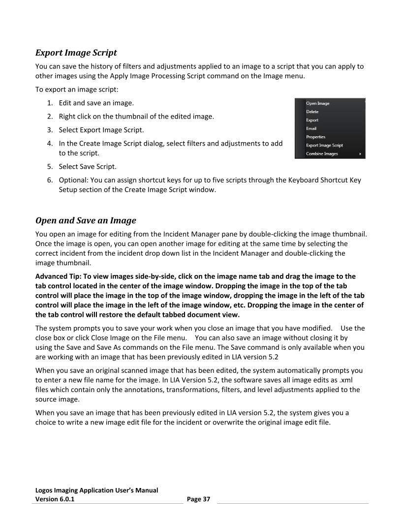
Export Image Script You can save the history of filters and adjustments applied to an image to a script that you can apply to other images using the Apply Image Processing Script command on the Image menu.
To export an image script:
1. Edit and save an image.
2. Right click on the thumbnail of the edited image.
3. Select Export Image Script.
4. In the Create Image Script dialog, select filters and adjustments to add to the script.
5. Select Save Script.
6. Optional: You can assign shortcut keys for up to five scripts through the Keyboard Shortcut Key Setup section of the Create Image Script window.
Open and Save an Image You open an image for editing from the Incident Manager pane by double-clicking the image thumbnail. Once the image is open, you can open another image for editing at the same time by selecting the correct incident from the incident drop down list in the Incident Manager and double-clicking the image thumbnail.
Advanced Tip: To view images side-by-side, click on the image name tab and drag the image to the tab control located in the center of the image window. Dropping the image in the top of the tab control will place the image in the top of the image window, dropping the image in the left of the tab control will place the image in the left of the image window, etc. Dropping the image in the center of the tab control will restore the default tabbed document view.
The system prompts you to save your work when you close an image that you have modified. Use the close box or click Close Image on the File menu. You can also save an image without closing it by using the Save and Save As commands on the File menu. The Save command is only available when you are working with an image that has been previously edited in LIA version 5.2
When you save an original scanned image that has been edited, the system automatically prompts you to enter a new file name for the image. In LIA Version 5.2, the software saves all image edits as .xml files which contain only the annotations, transformations, filters, and level adjustments applied to the source image.
When you save an image that has been previously edited in LIA version 5.2, the system gives you a choice to write a new image edit file for the incident or overwrite the original image edit file.

Logos Imaging Application User’s Manual Version 6.0.1 Page 38
Save Selection to Folder You can copy a section of an image to a folder for use in another program.
To copy a section of the image:
1. Click the Selection Tool on the toolbar.
2. Click and hold the left mouse button while you drag a rectangle over the portion of the image you want to copy.
3. Release the mouse button to end your selection.
4. Select Save Image to Folder command on the File Menu.
5. The image is saved to the export folder defined in the preferences using the date and time of the capture as the file name.

Logos Imaging Application User’s Manual Version 6.0.1 Page 39
Editing Images When you open an incident's image, you are able to change the look of the image by adjusting the levels, applying a filter, using Percept contrast enhancement, adding annotations, rotating the image, or stitching images. After editing the image, you can save your changes as a new image within the incident.
Use the menus at the top of the application window or the toolbars to change the image as needed, then save or close the image.

Logos Imaging Application User’s Manual Version 6.0.1 Page 40
Adjustments Use the commands on the Image > Adjustments menu to alter the look of the image.
• Original - Removes all filters and resets level adjustments to the settings of the saved image. Original does not undo rotate transformations.
• Auto Correct - Applies predefined filters, including Invert, to allow users a quick option for image enhancement. Note: Auto Correct is available by clicking the AUTO button on the Tools palette.
• Auto Level - Stretches the image histogram to the full dynamic range of the image format. Image normalization, or contrast stretching, is used to enhance contrast in an image.
• Adaptive Equalization - Performs a contrast limited adaptive histogram equalization on an image to increase contrast.
• Percept Contrast - Adapts the levels of gray in Logos images to be better perceived by human eyesight.
Levels Use the sliders in the Image Correction > Levels pane to alter the look of the image. You can save the altered image when done.
Tip: If you do not like the effect of the change you made, use the Edit menu to go back one or more stages.
• Histogram - Displays the brightness levels of the image and lets you use a slider to adjust them.
Expanded View - Opens a large histogram map to allow more precise adjustment.
Reset - Resets histogram sliders to original settings.
Auto - Performs an image normalization process.
• Brightness, Contrast, and Gamma - Adjusts the brightness, contrast, and gamma (the shadow and highlight tones) of the image.
Reset - Resets brightness, contrast, and gamma sliders to original settings.

Logos Imaging Application User’s Manual Version 6.0.1 Page 41
Filters Use the commands on the Image > Filters menu or click on the filter's thumbnail on the Image Correction > Filters pane to alter the look of the image. By default, only four filters are displayed. Click the drop down arrow to display thumbnails for all available filters.
Tip: If you do not like the effect of the change you made, use the Edit menu to go back one or more stages.
• Original - Removes all applied filters and resets levels to the settings of the saved image. Original does not undo rotations.
• Adaptive Histogram - Performs a contrast limited adaptive histogram equalization on an image to increase contrast.
• Equalize - Equalizes the brightness of the image.
• Invert - Reverses the image's colors. For example, black becomes white, red becomes green, etc.
• Emboss - Accentuates high-contrast edges and flattens low-contrast areas, making a relief-map type image.
• Outline - Changes the image so the edges of the image are outlined with dark lines against a light background.
• Smooth - Makes the image's edges less sharp.
• Sharpen - Makes the image's edges appear more sharply defined.
• Despeckle - removes noise from images without blurring edges
• Colorize - Colors the entire image.
Percept Use the Percept Contrast command on the Image > Adjustments menu, click one of the presets on the Percept panel, or use the slider in the Percept panel to automatically adjust the contrast in the active image. The Percept Contrast tool works on grayscale images.
Logos Imaging systems produce images with up to 65,536 levels of gray, while the human eye is capable of distinguishing less than 100 levels of gray. Percept dynamic compression compensates for this effect by adapting the levels of gray in Logos images to be better perceived by human eyesight irrespective of brightness or the influence of adjacent areas.
Note: Percept can only be applied once to each image.

Logos Imaging Application User’s Manual Version 6.0.1 Page 42
Apply Image ProcessingScript You can apply previously created image processing scripts using the Apply Image Processing Script command on the Image menu.
To apply an image processing script:
1. Open an image for editing.
2. Choose the script you wish to apply by using the shortcut key assigned to the script (you can view shortcut key assignments by right-clicking on the image thumbnail and selecting Export Image Script), by selecting the script from the most recently used list in the Image > Apply Image Processing Script menu, or by browsing to the script through the Image > Apply Image Processing Script menu.
Annotations Use the commands on the Annotation menu or toolbar to manipulate text or shapes on top of an image. For example, if you want to point out a particular area of the photograph, use one of the shape annotations -- line, rectangle, ellipse, polygon, or polyline -- to point to or enclose the area of interest. You could also add text to describe why the pinpointed area is of interest.
Tip: If you do not like the effect of the change you made, use the Undo command on the Edit menu or Ctrl + Z to go back one or more stages.
• Pointer - Switches to the cursor mode so that you can select an annotation to change or delete. For example, select an existing rectangular annotation and then drag on any corner or line midsection to change the size. Click any other part of the outline to move it.
• Text - Adds text to the image. To add text to the image, select the text tool, choose font attributes for the text from the toolbar, move the cursor to the starting point of the text box, click and hold the left mouse button, drag the cursor to the ending point of the text box, release the left mouse button, type the text, and click outside of the text box to complete the entry.
Note: When you use one of the shape annotations, use the Options Bar to select the width and color of the lines, the start and end arrows, and the fill color of enclosed shapes before drawing shapes and/or lines. Adjust the opacity of the shape's fill color using the Opacity slider.
• Line - Draws a line from one point to the other. To draw a line, select the line tool, move the cursor to the starting point of the line, click and hold the left mouse button, drag the cursor to the ending point of the line, and release the left mouse button. To measure the line as it is drawn or add a line profile, select the feature in the options bar.
• Polyline - Draws a line between points. To draw a polyline, click the start point, then click the next point, then click the next point, and so on. Double clicking the final point closes the draw polyline function.

Logos Imaging Application User’s Manual Version 6.0.1 Page 43
• Rectangle - Draws a rectangle. To draw a rectangle, select the rectangle tool, move the cursor to the starting point of the rectangle, click and hold the left mouse button, drag the cursor to the ending point of the rectangle, and release the left mouse button.
• Ellipse - Works the same as Rectangle, but draws a circular or oval figure.
• Measure - Measures the straight-line length or angle of a previously drawn annotation. After an annotation is drawn, choose the Measure tool and then select the annotation by clicking on an annotation line to obtain a straight-line measurement. Obtain an angle clicking the vertex of an angle created with the polyline tool.
• Calibration - Adjusts the image resolution to account for geometric magnification in radiographic images. To calibrate an image based upon the size of a known object, select the calibration tool, draw a line along the length of a known object (do not select the line tool), and enter the actual length of the line.

Logos Imaging Application User’s Manual Version 6.0.1 Page 44
Stitch Images
To stitch images:
1. In the Incident Manager pane, click Stitch Images or select New Stitch Image from the File > New menu.
2. In the Image pane click the Add Row and/or Add Column icons to define the number and orientation of your image matrix. You can reset the image matrix by clicking the Reset button.
3. Drag images from the Image Manager and drop them over the appropriate image text in the stitch window.
4. After dropping each image, the Image pane will refresh to show the stitched image.
5. At any time, you can select an image in the Image pane for nudging. The nudge buttons are at the bottom of the Image pane.
6. After you have the output you desire; clicking the Save Image to open the stitched image for editing.

Logos Imaging Application User’s Manual Version 6.0.1 Page 45
Print an Image Use the Print command on the File menu or Ctrl+P to print the image in the active image editor window.
To print full-size 8x17 images, it is first necessary to set up a custom paper size. Please refer to the manual that came with your printer for further assistance with creating custom paper sizes.
Region of Interest Use the Select Region command on the Tools menu or click of Region of Interest tool on the Tools palette to choose a section of the image for localized processing. With the Region of Interest tool selected, all adjustments, levels, filters, and Percept functions will only be applied to the selected area.
To clear the Region of Interest selection, click on the active image outside of the selected area or click the Reset button on the Options bar.
To crop the image to the selected area, click the Crop button on the Options bar.
Recover and Undo The Undo and Redo commands let you undo or redo operations performed on the active image.
To undo an operation, choose Undo on the Edit menu or use Ctrl+Z.
To redo an operation, choose Redo on the Edit menu or use Ctrl+Y.
You can also choose Original from the Image > Adjustments menu or in the Image Correction > Filters pane to restore the image to the settings of the saved image.
Note: Original does not undo image rotation.

Logos Imaging Application User’s Manual Version 6.0.1 Page 46
View Images
Zoom You can zoom in or zoom out to see an image better by doing any of the following:
• Choose the Zoom In or Zoom Out commands on the View menu
• Use Ctrl+ Add or Ctrl+ Subtract accelerator keys
• Adjust the slider in the bottom left of the image window
• Adjust the slider in the Pan Control panel
If you want the image to be as large as it can without being larger than the window, select Fit to Window icon command in the View menu.
Pan Control The Pan Control pane allows you to adjust the current view of your image. The colored box in the Pan Control's thumbnail display corresponds to the viewable area in the image window.
After zooming in on an image, you can use the Pan Control to move the view area by dragging the proxy view area box in the image thumbnail.
Rotate Images Use the commands on the Image > Rotate menu or click on the command's icon on the Tools bar to alter the look of the image. You can save the altered image when done.
Tip: If you do not like the effect of the change you made, use the Edit menu to go back one or more stages.
• Rotate 90 Degrees Left
• Rotate 90 Degrees Right
• Rotate 180 Degrees
• Flip Horizontal - Turns the image 180 degrees around a vertical axis. This command is useful if image plates were loaded in the plate holder backwards.
• Flip Vertical - Turns the image 180 degrees around a horizontal axis.

Logos Imaging Application User’s Manual Version 6.0.1 Page 47
Magnify Tool You can zoom in closely on an area of an image using the Magnify tool . The magnify tool works as a floating magnifying glass.
To use the Magnify tool:
1. Select the Magnify tool icon on the Tools bar or on the Tools menu.
2. Select the magnification factor and filter for the tool in the drop down menus. You can resize the Magnify tool by dragging the bottom right corner of the tool.
3. While holding the left mouse button with the cursor over the Magnify tool, move your mouse over areas of interest to magnify that area.
4. To turn the Magnify tool off, select another tool or select the Magnify tool icon on the toolbar or on the Tools menu.
Note: You can capture an area of interest in the Magnify tool by double-clicking the tool's viewing area. Double-clicking the tool's viewing area will clear the area of interest.
Grid and Annotations You can select whether annotations are visible by using the Show Annotations command in the View menu.
You can select whether the grid is visible by using the Show Grid command in the View menu.
A check mark beside the View menu options indicates that the item is viewable in the current display.