Table of Contents Car Access Systems - meeknet Access Systems.pdf · 5 Car Access Systems History...
58
Revision Date: 07/11 Car Access Systems Introduction . . . . . . . . . . . . . . . . . . . . . . . . . . . . . . . . . . . . . . . . . . . . . . . . . .5 History of Electronic Vehicle Immobilization at BMW . . . . . . . . . . . . . . . .5 EWS1 . . . . . . . . . . . . . . . . . . . . . . . . . . . . . . . . . . . . . . . . . . . . . . . . . . . . . .5 EWS2 . . . . . . . . . . . . . . . . . . . . . . . . . . . . . . . . . . . . . . . . . . . . . . . . . . . . . .6 EWS3 and EWS3.2 . . . . . . . . . . . . . . . . . . . . . . . . . . . . . . . . . . . . . . . . . .8 EWS3.3 . . . . . . . . . . . . . . . . . . . . . . . . . . . . . . . . . . . . . . . . . . . . . . . . . . . . .9 CAS with EWS3.3 . . . . . . . . . . . . . . . . . . . . . . . . . . . . . . . . . . . . . . . . . .10 Car Access System 3 with EWS4 . . . . . . . . . . . . . . . . . . . . . . . . . . . . . .11 Replacement of Control Units . . . . . . . . . . . . . . . . . . . . . . . . . . . . . . . . . . .11 Start Enable . . . . . . . . . . . . . . . . . . . . . . . . . . . . . . . . . . . . . . . . . . . . . . . . . .13 Time-based Query . . . . . . . . . . . . . . . . . . . . . . . . . . . . . . . . . . . . . . . . . . . .14 Key Memory Expansion in CAS3 . . . . . . . . . . . . . . . . . . . . . . . . . . . . .14 Car Access System 3 (E70) . . . . . . . . . . . . . . . . . . . . . . . . . . . . . . . . . . .16 History of the Car Access System . . . . . . . . . . . . . . . . . . . . . . . . . . . . . . .16 IPO Car Access System 3 (CAS 3) . . . . . . . . . . . . . . . . . . . . . . . . . . . . . .17 System Circuit Diagram - CAS 3 . . . . . . . . . . . . . . . . . . . . . . . . . . . . . . . .18 Functional Overview . . . . . . . . . . . . . . . . . . . . . . . . . . . . . . . . . . . . . . . . . . .20 Terminal Control (E70) . . . . . . . . . . . . . . . . . . . . . . . . . . . . . . . . . . . . . . .21 Terminal Control (in Comfort Access) . . . . . . . . . . . . . . . . . . . . . . . . . .21 Electronic Vehicle Immobilizer 3 (EWS 3) . . . . . . . . . . . . . . . . . . . . . .22 Electronic Vehicle Immobilizer 4 (EWS 4) . . . . . . . . . . . . . . . . . . . . . .22 Design of EWS 4 . . . . . . . . . . . . . . . . . . . . . . . . . . . . . . . . . . . . . . . . . . .22 Start Enable through EWS . . . . . . . . . . . . . . . . . . . . . . . . . . . . . . . . . . .23 Data Transmission . . . . . . . . . . . . . . . . . . . . . . . . . . . . . . . . . . . . . . .24 Secret Key . . . . . . . . . . . . . . . . . . . . . . . . . . . . . . . . . . . . . . . . . . . . . . . . .24 Gearbox Enable . . . . . . . . . . . . . . . . . . . . . . . . . . . . . . . . . . . . . . . . . . . . . . .25 Start Value Matching . . . . . . . . . . . . . . . . . . . . . . . . . . . . . . . . . . . . . . . .25 Service Information (CAS 3) . . . . . . . . . . . . . . . . . . . . . . . . . . . . . . . . . .26 Emergency Release . . . . . . . . . . . . . . . . . . . . . . . . . . . . . . . . . . . . . . . . . . .26 Vehicle Data Storage (CAS 3) . . . . . . . . . . . . . . . . . . . . . . . . . . . . . . . . . . .28 Data for Condition-based Service . . . . . . . . . . . . . . . . . . . . . . . . . . . . .28 Manual Update of CBS Data . . . . . . . . . . . . . . . . . . . . . . . . . . . . . .28 Manual Update of Fault Memory Data . . . . . . . . . . . . . . . . . . . . . .28 Control Unit Replacement . . . . . . . . . . . . . . . . . . . . . . . . . . . . . . . . . . . . . .29 Subject Page Table of Contents Initial Print Date: 07/10 meeknet.co.uk/e64
-
Upload
trinhthien -
Category
Documents
-
view
222 -
download
0
Transcript of Table of Contents Car Access Systems - meeknet Access Systems.pdf · 5 Car Access Systems History...

Revision Date: 07/11
Car Access Systems
Introduction . . . . . . . . . . . . . . . . . . . . . . . . . . . . . . . . . . . . . . . . . . . . . . . . . .5History of Electronic Vehicle Immobilization at BMW . . . . . . . . . . . . . . . .5
EWS1 . . . . . . . . . . . . . . . . . . . . . . . . . . . . . . . . . . . . . . . . . . . . . . . . . . . . . .5EWS2 . . . . . . . . . . . . . . . . . . . . . . . . . . . . . . . . . . . . . . . . . . . . . . . . . . . . . .6EWS3 and EWS3.2 . . . . . . . . . . . . . . . . . . . . . . . . . . . . . . . . . . . . . . . . . .8EWS3.3 . . . . . . . . . . . . . . . . . . . . . . . . . . . . . . . . . . . . . . . . . . . . . . . . . . . . .9CAS with EWS3.3 . . . . . . . . . . . . . . . . . . . . . . . . . . . . . . . . . . . . . . . . . .10
Car Access System 3 with EWS4 . . . . . . . . . . . . . . . . . . . . . . . . . . . . . .11Replacement of Control Units . . . . . . . . . . . . . . . . . . . . . . . . . . . . . . . . . . .11Start Enable . . . . . . . . . . . . . . . . . . . . . . . . . . . . . . . . . . . . . . . . . . . . . . . . . .13Time-based Query . . . . . . . . . . . . . . . . . . . . . . . . . . . . . . . . . . . . . . . . . . . .14
Key Memory Expansion in CAS3 . . . . . . . . . . . . . . . . . . . . . . . . . . . . .14
Car Access System 3 (E70) . . . . . . . . . . . . . . . . . . . . . . . . . . . . . . . . . . .16History of the Car Access System . . . . . . . . . . . . . . . . . . . . . . . . . . . . . . .16IPO Car Access System 3 (CAS 3) . . . . . . . . . . . . . . . . . . . . . . . . . . . . . .17System Circuit Diagram - CAS 3 . . . . . . . . . . . . . . . . . . . . . . . . . . . . . . . .18Functional Overview . . . . . . . . . . . . . . . . . . . . . . . . . . . . . . . . . . . . . . . . . . .20
Terminal Control (E70) . . . . . . . . . . . . . . . . . . . . . . . . . . . . . . . . . . . . . . .21Terminal Control (in Comfort Access) . . . . . . . . . . . . . . . . . . . . . . . . . .21Electronic Vehicle Immobilizer 3 (EWS 3) . . . . . . . . . . . . . . . . . . . . . .22Electronic Vehicle Immobilizer 4 (EWS 4) . . . . . . . . . . . . . . . . . . . . . .22Design of EWS 4 . . . . . . . . . . . . . . . . . . . . . . . . . . . . . . . . . . . . . . . . . . .22Start Enable through EWS . . . . . . . . . . . . . . . . . . . . . . . . . . . . . . . . . . .23
Data Transmission . . . . . . . . . . . . . . . . . . . . . . . . . . . . . . . . . . . . . . .24Secret Key . . . . . . . . . . . . . . . . . . . . . . . . . . . . . . . . . . . . . . . . . . . . . . . . .24
Gearbox Enable . . . . . . . . . . . . . . . . . . . . . . . . . . . . . . . . . . . . . . . . . . . . . . .25Start Value Matching . . . . . . . . . . . . . . . . . . . . . . . . . . . . . . . . . . . . . . . .25
Service Information (CAS 3) . . . . . . . . . . . . . . . . . . . . . . . . . . . . . . . . . .26Emergency Release . . . . . . . . . . . . . . . . . . . . . . . . . . . . . . . . . . . . . . . . . . .26Vehicle Data Storage (CAS 3) . . . . . . . . . . . . . . . . . . . . . . . . . . . . . . . . . . .28
Data for Condition-based Service . . . . . . . . . . . . . . . . . . . . . . . . . . . . .28Manual Update of CBS Data . . . . . . . . . . . . . . . . . . . . . . . . . . . . . .28Manual Update of Fault Memory Data . . . . . . . . . . . . . . . . . . . . . .28
Control Unit Replacement . . . . . . . . . . . . . . . . . . . . . . . . . . . . . . . . . . . . . .29
Subject Page
Table of Contents
Initial Print Date: 07/10
meeknet.co.uk/e64
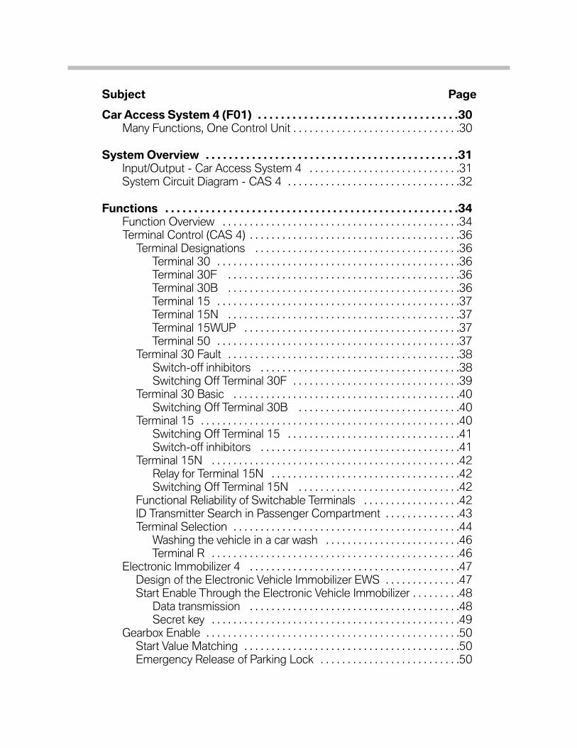
Car Access System 4 (F01) . . . . . . . . . . . . . . . . . . . . . . . . . . . . . . . . . . .30Many Functions, One Control Unit . . . . . . . . . . . . . . . . . . . . . . . . . . . . . . .30
System Overview . . . . . . . . . . . . . . . . . . . . . . . . . . . . . . . . . . . . . . . . . . . .31Input/Output - Car Access System 4 . . . . . . . . . . . . . . . . . . . . . . . . . . . .31System Circuit Diagram - CAS 4 . . . . . . . . . . . . . . . . . . . . . . . . . . . . . . . .32
Functions . . . . . . . . . . . . . . . . . . . . . . . . . . . . . . . . . . . . . . . . . . . . . . . . . . .34Function Overview . . . . . . . . . . . . . . . . . . . . . . . . . . . . . . . . . . . . . . . . . . . .34Terminal Control (CAS 4) . . . . . . . . . . . . . . . . . . . . . . . . . . . . . . . . . . . . . . .36
Terminal Designations . . . . . . . . . . . . . . . . . . . . . . . . . . . . . . . . . . . . . .36Terminal 30 . . . . . . . . . . . . . . . . . . . . . . . . . . . . . . . . . . . . . . . . . . . . .36Terminal 30F . . . . . . . . . . . . . . . . . . . . . . . . . . . . . . . . . . . . . . . . . . .36Terminal 30B . . . . . . . . . . . . . . . . . . . . . . . . . . . . . . . . . . . . . . . . . . .36Terminal 15 . . . . . . . . . . . . . . . . . . . . . . . . . . . . . . . . . . . . . . . . . . . . .37Terminal 15N . . . . . . . . . . . . . . . . . . . . . . . . . . . . . . . . . . . . . . . . . . .37Terminal 15WUP . . . . . . . . . . . . . . . . . . . . . . . . . . . . . . . . . . . . . . . .37Terminal 50 . . . . . . . . . . . . . . . . . . . . . . . . . . . . . . . . . . . . . . . . . . . . .37
Terminal 30 Fault . . . . . . . . . . . . . . . . . . . . . . . . . . . . . . . . . . . . . . . . . . .38Switch-off inhibitors . . . . . . . . . . . . . . . . . . . . . . . . . . . . . . . . . . . . .38Switching Off Terminal 30F . . . . . . . . . . . . . . . . . . . . . . . . . . . . . . .39
Terminal 30 Basic . . . . . . . . . . . . . . . . . . . . . . . . . . . . . . . . . . . . . . . . . .40Switching Off Terminal 30B . . . . . . . . . . . . . . . . . . . . . . . . . . . . . .40
Terminal 15 . . . . . . . . . . . . . . . . . . . . . . . . . . . . . . . . . . . . . . . . . . . . . . . .40Switching Off Terminal 15 . . . . . . . . . . . . . . . . . . . . . . . . . . . . . . . .41Switch-off inhibitors . . . . . . . . . . . . . . . . . . . . . . . . . . . . . . . . . . . . .41
Terminal 15N . . . . . . . . . . . . . . . . . . . . . . . . . . . . . . . . . . . . . . . . . . . . . .42Relay for Terminal 15N . . . . . . . . . . . . . . . . . . . . . . . . . . . . . . . . . . .42Switching Off Terminal 15N . . . . . . . . . . . . . . . . . . . . . . . . . . . . . .42
Functional Reliability of Switchable Terminals . . . . . . . . . . . . . . . . . .42ID Transmitter Search in Passenger Compartment . . . . . . . . . . . . . .43Terminal Selection . . . . . . . . . . . . . . . . . . . . . . . . . . . . . . . . . . . . . . . . . .44
Washing the vehicle in a car wash . . . . . . . . . . . . . . . . . . . . . . . . .46Terminal R . . . . . . . . . . . . . . . . . . . . . . . . . . . . . . . . . . . . . . . . . . . . . .46
Electronic Immobilizer 4 . . . . . . . . . . . . . . . . . . . . . . . . . . . . . . . . . . . . . . .47Design of the Electronic Vehicle Immobilizer EWS . . . . . . . . . . . . . .47Start Enable Through the Electronic Vehicle Immobilizer . . . . . . . . .48
Data transmission . . . . . . . . . . . . . . . . . . . . . . . . . . . . . . . . . . . . . . .48Secret key . . . . . . . . . . . . . . . . . . . . . . . . . . . . . . . . . . . . . . . . . . . . . .49
Gearbox Enable . . . . . . . . . . . . . . . . . . . . . . . . . . . . . . . . . . . . . . . . . . . . . . .50Start Value Matching . . . . . . . . . . . . . . . . . . . . . . . . . . . . . . . . . . . . . . . .50Emergency Release of Parking Lock . . . . . . . . . . . . . . . . . . . . . . . . . .50
Subject Page

System Components . . . . . . . . . . . . . . . . . . . . . . . . . . . . . . . . . . . . . . . . .52Car Access System Connections . . . . . . . . . . . . . . . . . . . . . . . . . . . . . . .52Other Components . . . . . . . . . . . . . . . . . . . . . . . . . . . . . . . . . . . . . . . . . . . .53
START-STOP Button . . . . . . . . . . . . . . . . . . . . . . . . . . . . . . . . . . . . . . .53Emergency Start Coil . . . . . . . . . . . . . . . . . . . . . . . . . . . . . . . . . . . . . . .53Remote Control Receiver . . . . . . . . . . . . . . . . . . . . . . . . . . . . . . . . . . . .54Input Components . . . . . . . . . . . . . . . . . . . . . . . . . . . . . . . . . . . . . . . . .54
Service Information (CAS 4) . . . . . . . . . . . . . . . . . . . . . . . . . . . . . . . . . .55Vehicle Data Storage . . . . . . . . . . . . . . . . . . . . . . . . . . . . . . . . . . . . . . . . . .55
Updating Service Data . . . . . . . . . . . . . . . . . . . . . . . . . . . . . . . . . . . . . .56Updating Service Key Data . . . . . . . . . . . . . . . . . . . . . . . . . . . . . . . . . .56
Automatic updating . . . . . . . . . . . . . . . . . . . . . . . . . . . . . . . . . . . . .56Manual updating . . . . . . . . . . . . . . . . . . . . . . . . . . . . . . . . . . . . . . . .57
Control Unit Replacement . . . . . . . . . . . . . . . . . . . . . . . . . . . . . . . . . . . . .58
Subject Page

4Car Access Systems
Car Access Systems
Model: All
Production: All
After completion of this module you will be able to:
• Understand the history of electronic vehicle immobilization systems.
• Describe the difference between CAS3 and CAS4
• Describe the operation of each system.
5Car Access Systems
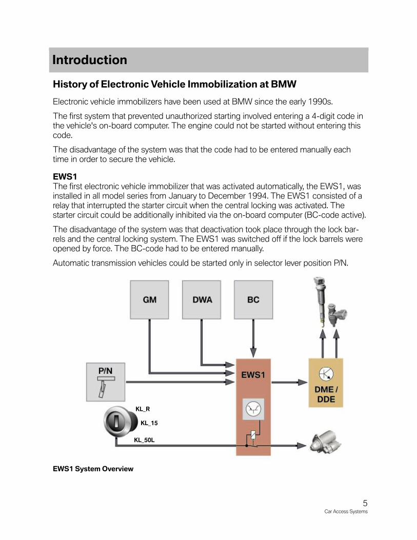
History of Electronic Vehicle Immobilization at BMW
Electronic vehicle immobilizers have been used at BMW since the early 1990s.
The first system that prevented unauthorized starting involved entering a 4-digit code inthe vehicle's on-board computer. The engine could not be started without entering thiscode.
The disadvantage of the system was that the code had to be entered manually eachtime in order to secure the vehicle.
EWS1The first electronic vehicle immobilizer that was activated automatically, the EWS1, wasinstalled in all model series from January to December 1994. The EWS1 consisted of arelay that interrupted the starter circuit when the central locking was activated. Thestarter circuit could be additionally inhibited via the on-board computer (BC-code active).
The disadvantage of the system was that deactivation took place through the lock bar-rels and the central locking system. The EWS1 was switched off if the lock barrels wereopened by force. The BC-code had to be entered manually.
Automatic transmission vehicles could be started only in selector lever position P/N.
EWS1 System Overview
Introduction
KL_50L
KL_15
KL_R

EWS2The first electronically coded vehicle immobilizer, the EWS2, was installed in all vehiclesas from January 1995. The EWS2 prevented the engine from being started after tamper-ing with the ignition lock or the lock barrels in the doors. The EWS2 consists of the fol-lowing components:
• Vehicle key with transponder chip.
• Ring antenna at ignition lock.
• Transceiver module for data exchange with the key.
• EWS control unit for start enable, terminal 50.
• Digital motor electronics for enabling the ignition/injection systems.
The electronic vehicle immobilizer consists of an EWS control unit that manages up to10 vehicle keys and the digital motor electronics DME/DDE. The vehicle-specific datafrom the BMW database are programmed ex-factory in the control unit and assigneddirectly to the vehicle. In turn, the DME is assigned to the EWS control unit via the indi-vidual control unit number ISN.
EWS2 System Overview
6Car Access Systems
125 KHz
KL_50L
In order to start the vehicle, the key data in the transponder chip are read out via the ringantenna at the ignition key and the transceiver module. The transceiver module transfersthe key data via a bidirectional data cable to the EWS2.
The EWS control unit checks the correctness of the key data and only then sends anenable signal to the DME and the starter. After the engine has been started, the EWScontrol unit generates new key data (variable code) and sends them back via the bidirec-tional data line to the transponder chip in the key.
The EWS control unit sends the enable signal in the form of a 32 bit enable code via aunidirectional data line to the DME.
The enable code is formed from the ISN number (individual control unit number) of theDME and an internally calculated counter.
The enable code is stored in the DME. During the next start procedure, the next numberis sent and the counter is incremented by 1. The system is OK as long as the counter inthe EWS and the DME is incremented consistently.
If the counters run more than 5 starts apart the ignition and the fuel injection will nolonger be enabled in the DME.
This situation can occur when the engine is stalled just after starting, e.g. in drivingschool vehicles. The EWS recognized the start and increased the counter. The DME wasbusy with the start procedure (processor utilization) and has not yet stored the enablecode and therefore not incremented the counter.
In this case, it is necessary to perform EWS/DME matching via the diagnostic interface.As part of this procedure, the DME transfers and stores the ISN in the EWS control unit.The two counters are also reset.
With the aim of protecting the starter, the DME transfers the engine speed signal to theEWS.
If the engine is cranked but does not start, the start procedure is interrupted after a specific time defined in the control unit. Additional conditions such as the status of thecentral locking, automatic transmission range, DWS function, BC function are read in via separate interfaces in the EWS2 and evaluated.
Since the DME/DDE is assigned to the EWS control unit by means ofthe ISN, a DME can be replaced from another vehicle for test purposes.EWS-DME matching, however, must be performed for this purpose inorder to transfer the new ISN to the EWS.
7Car Access Systems

EWS3 and EWS3.2The EWS3 was introduced in the E38 as from September 1996. Its installation in theE39 followed in March 1997. Since these models are vehicles equipped with K-Bussystems networks, the general conditions are read in via the K-Bus.
Likewise, diagnosis as well as EWS-DME matching take place via the K-Bus.
The new feature of the EWS3 is that it no longer has the transceiver. The EWS3 nowreads in the key data from the transponder chip directly via the ring antenna. After theengine has been started, the new variable code is transferred directly to the key.
The enable procedure for the starter and DME remains the same.
The EWS3 is renamed EWS3.2 with the introduction of the EWS3.3. The reason for thisis the different matching procedures between the EWS and DME. In the case of theEWS3.2, EWS-DME matching takes place based on the ISN number, i.e. the same pro-cedure as used in the EWS2.
EWS3/3.2 with K-Bus System Overview
8Car Access Systems
125 KHz
KL_50L

EWS3.3The EWS3.3 was introduced in the E46 as from April 1998. The EWS3.3. differs fromthe 3.2 version in terms of the following functions.
The 32 bit secret key was retained but the encryption procedure was changed. Theentire vehicle data and the secret key are contained in the EWS control unit and assigneddirectly to the vehicle.
The DME/DDE is now assigned to the EWS control unit by way of programming.
Programming takes place via the PT-CAN and is possible only with an empty (blank) con-trol unit.
Note: Consequently, swapping the control unit from another vehicle is nolonger possible.
The EWS control unit contains the starter relay for enabling terminal 50 to the starter.
The EWS control unit sends a permanently changing code for the purpose of enablingthe DME. This code contains information on the EWS control unit that is compared withthe programmed information. If the sent data is OK, the DME/DDE will enable the ignitionand fuel injection systems.
EWS3.3 System Overview
9Car Access Systems
125 KHz
KL_50L
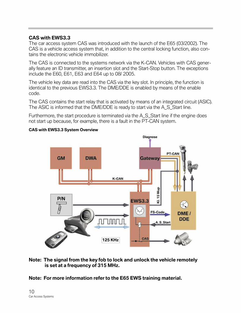
CAS with EWS3.3The car access system CAS was introduced with the launch of the E65 (03/2002). TheCAS is a vehicle access system that, in addition to the central locking function, also con-tains the electronic vehicle immobilizer.
The CAS is connected to the systems network via the K-CAN. Vehicles with CAS gener-ally feature an ID transmitter, an insertion slot and the Start-Stop button. The exceptionsinclude the E60, E61, E63 and E64 up to 08/ 2005.
The vehicle key data are read into the CAS via the key slot. In principle, the function isidentical to the previous EWS3.3. The DME/DDE is enabled by means of the enablecode.
The CAS contains the start relay that is activated by means of an integrated circuit (ASIC).The ASIC is informed that the DME/DDE is ready to start via the A_S_Start line.
Furthermore, the start procedure is terminated via the A_S_Start line if the engine doesnot start up because, for example, there is a fault in the PT-CAN system.
CAS with EWS3.3 System Overview
Note: The signal from the key fob to lock and unlock the vehicle remotelyis set at a frequency of 315 MHz.
Note: For more information refer to the E65 EWS training material.
10Car Access Systems
125 KHz
11Car Access Systems
The car access system 3 with the new generation of electronic vehicle immobilizerEWS4 was introduced in E92 vehicles with the N52/N54 gasoline engine. The EWS4 isa vehicle immobilizer that prevents unauthorized engine start.
The car access system 3 with an EWS3 interface was first used on diesel engine vehi-cles. This system evolved into CAS3 with EWS4.
The vehicle immobilizer consists of the ID transmitter which is identical for the vehicleand therefore to CAS3. CAS3 exchanges data with the DME via the CAS-Bus and can-cels the vehicle immobilization function.
The EWS4 uses a new, modern encryption method. A 128 bit long secret key isassigned to each vehicle and stored in the BMW database.
This secret key is known only to BMW. The secret key is programmed and locked in theCAS and in the DME control unit. Once entered in the control unit, the secret key can nolonger be changed or deleted. This therefore means that each control unit is assigned toa specific vehicle.
One control unit in the system sends an encrypted code to another control unit for thepurpose of checking the authorization. In turn, this control unit sends back a correspond-ing code.
Replacement of Control Units
The procedure described below must be followed in order to replace a defective controlunit (CAS/DME).
The required control unit is ordered together with the necessary vehicle data (VIN) fromone of the worldwide central stores, e.g. in Dingolfing for Europe.
A new "blank" control unit is programmed with the corresponding program data for thevehicle and the secret key from the BMW database, locked and sent to the dealer.
The new control unit is installed in the vehicle and started. No matching procedure isnecessary as in earlier EWS systems.
Since the control units are assigned to the specific vehicle, replace-ment with a unit from another vehicle is not possible.
Beginning with the introduction of the E70 and as part of a rollingupdate, most current (BN 2000) vehicles use CAS3 in combinationwith the EWS4 system. For further information regarding these systems refer to the Car Access System (E70) section of this trainingmaterial.
Car Access System 3 with EWS4

Electronic Vehicle Immobilizer 4 in the E92
Index Explanation Index Explanation
1 Car access system with EWS4 5 Junction box
2 Starter 6 Battery
3 Injection relay 7 Start/Stop button
4 Digital motor electronics MSV80/MSD80 8 Holder
12Car Access Systems

The electronic vehicle immobilizer consists of several components. In the E92 thesecomponents are the CAS3 and the DME MSV80/MSD80.
The CAS3 contains the software for the EWS4 and, with corresponding identification ofthe ID transmitter, the enable of terminal R, 15 and 50 for the starter. The enable for theignition and fuel injection systems is resident in the DME.
Both control units are connected by the KCAN, the junction box serving as the gatewayand the PT-CAN. Data are also exchanged on the CAS-Bus. The data are always trans-mitted parallel via both bus systems. The signals that arrive first are used.
The DME activates the fuel injection relay for the power supply of the fuel injectors. TheDME features a direct line (A_S_Start) to the starter relay in the CAS in order to initiatethe start procedure and, if necessary, to terminate it, e.g. in the event of a PT-CAN fault ora faulty signal, e.g. engine speed signal.
Start Enable
The start procedure is enabled by means of a special request and response procedureknown as challenge-response.
The DME generates a random number in a random generator and sends it as the chal-lenge to the CAS. The CAS and the DME contain the same secret key and both controlunits use the same calculation algorithm.
The CAS now calculates the result from the received random number, the secret key andthe algorithm. The result is sent as the CAS response to the DME.
During this time, the DME now calculates the same random number with the secret keyand the algorithm and already knows the result. The response of the CAS is comparedwith the result of the DME. Start is enabled if the result is identical.
EWS4 Start Enable Procedure
13Car Access Systems

14Car Access Systems
Time-based Query
As from terminal R or terminal 15 ON, a query (challenge-response) is performed as longas the engine is not yet running. A fault code is entered in the CAS if no DME response isreceived approx. 10 seconds after the start of the query or if the response deviates.
Key Memory Expansion in CAS3The data memory of the remote key in vehicles equipped with CAS3 is increased from256 bytes to 512 bytes.
The benefit of this key memory expansion for the customer is that more accurate informa-tion on the time and scope of the workshop visit can be provided as part of the serviceacceptance procedure.
The following system network information can be read out from the identification trans-mitter with the key reader in the service workshop.
Data Previous New Remark
Mileage reading X Current mileage (km) reading of vehicle
Vehicle Identification (VIN) X
Key number X Number of identification transmitter
Service- relevant CC message X
DTC Information (fault code memory) XAs from SAM 25, the DTC data is indicated and
linked to possible measures in PUMA
NAVI-DVD version X Data status of NAVI-DVD
Engine oil XInformation on topping up or draining
the engine oil (overfilling)
Battery condition XChange status of the battery
in the vehicle
Integration stages XI-stage that left the factory, I-stage last programmed and
I-stage currently available in the dealership network

NOTESPAGE
15Car Access Systems

16Car Access Systems
The Car Access System now features the 3rd generation of control units. The electronicvehicle immobilizer 4 (EWS 4) is also used in connection with the Car Access System 3.The previous functions of the electronic vehicle immobilizer 3 have been retained.
The Car Access System 3 can therefore be operated together with the electronic vehicleimmobilizer 3 or 4. The digital motor electronics and the Car Access System 3 wereincorporated in the overall electronic vehicle immobilizer system in the E70.
In addition, the electronic transmission control is used as a further immobilizer. Theelectronic vehicle immobilizer 4 improves the antitheft properties of the vehicle. A longer cryptic code is used for the data exchange.
The cryptic code provides the enable to start the engine. The Car Access System 3 isbackwards compatible with the Car Access System 2. This means the functions of theCar Access System 2 are also included in the Car Access System 3.
The electronic vehicle immobilizer 3 or the electronic vehicle immobilizer 4 is useddepending on the engine installed and the associated digital engine management.
The table below shows the assignment of the engine management to the respectiveelectronic vehicle immobilizer.
History of the Car Access System
The Car Access System was used for the first time in the E65 (03/2002). It has under-gone continuous further development and has been successively introduced in variousBMW models.
CAS3 combined with EWS4 has been gradually installed in most (BN2000) vehicles (E6x, E8X, E9x and E7x) over the recent years.
With the introduction of the F01 in 2008 (the first of the BN2020 vehicles) the CarAccess 4 System was introduced.
Note: For more information regarding the Car Access 4 system installed in F0x vehicles refer to the Car Access System 4 (F01) section of thistraining material.
Vehicle Launch Date EngineEngine
ManagementEWS function
E70 10/06 N62B48O1 ME9.2.3 EWS 3
E70 10/06 N52B30O1 MSV80 EWS 4
Car Access System 3 (E70)
17Car Access Systems
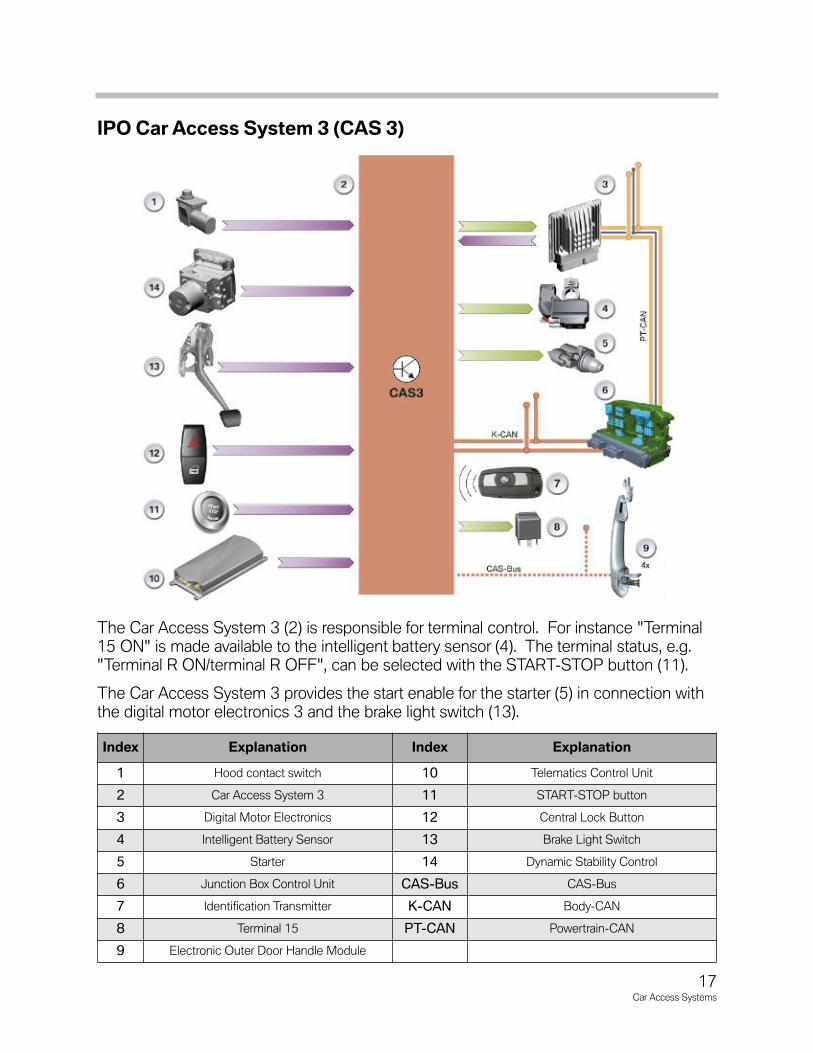
IPO Car Access System 3 (CAS 3)
The Car Access System 3 (2) is responsible for terminal control. For instance "Terminal15 ON" is made available to the intelligent battery sensor (4). The terminal status, e.g."Terminal R ON/terminal R OFF", can be selected with the START-STOP button (11).
The Car Access System 3 provides the start enable for the starter (5) in connection withthe digital motor electronics 3 and the brake light switch (13).
Index Explanation Index Explanation
1 Hood contact switch 10 Telematics Control Unit
2 Car Access System 3 11 START-STOP button
3 Digital Motor Electronics 12 Central Lock Button
4 Intelligent Battery Sensor 13 Brake Light Switch
5 Starter 14 Dynamic Stability Control
6 Junction Box Control Unit CAS-Bus CAS-Bus
7 Identification Transmitter K-CAN Body-CAN
8 Terminal 15 PT-CAN Powertrain-CAN
9 Electronic Outer Door Handle Module

System Circuit Diagram - CAS 3
18Car Access Systems

Legend for System Circuit Diagram - CAS3
Index Explanation Index Explanation
1 Car Access System 3 KL15_3 Terminal 15 (output 3)
2 Electronic Transmission Control Module KL15 Wup Terminal 15 (wake-up)
3 Hood contact switch KL30 Terminal 30
4 Dynamic Stability Control KL30g Terminal 15 (switched)
5 Digital Motor Electronics KL30g_f Terminal 15 (switched, fault)
6 Junction Box Control Unit KL50L Terminal 50 load
7 Footwell Module (FRM) KL54 Signal, brake light switch
8 Central-lock button/hazard warning switch KL54T Signal, brake light switch
9 Comfort Access (CA) CAS-Bus CAS-Bus
10 Remote control receiver in diversity module D-CAN Diagnosis CAN
11 START-STOP button K-CAN Body CAN
12 Holder PT-CAN Powertrain CAN
13 Brake Light Switch (BLS)A_S_
STARTStart/Start termination DME
KLR Terminal R FBD Remote control services
KLRACSM
Terminal R, Advanced Crash SafetyManagement
WUPFBD
Wake-up, remote control services
KL15_1 Terminal 15 (output 1) EWS 3 Electronic Vehicle Immobilizer 3
KL15_2 Terminal 15 (output 2) EWS 4 Electronic Vehicle Immobilizer 4
19Car Access Systems
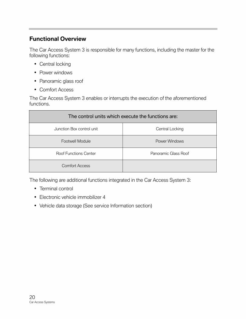
Functional Overview
The Car Access System 3 is responsible for many functions, including the master for thefollowing functions:
• Central locking
• Power windows
• Panoramic glass roof
• Comfort Access
The Car Access System 3 enables or interrupts the execution of the aforementionedfunctions.
The following are additional functions integrated in the Car Access System 3:
• Terminal control
• Electronic vehicle immobilizer 4
• Vehicle data storage (See service Information section)
The control units which execute the functions are:
Junction Box control unit Central Locking
Footwell Module Power Windows
Roof Functions Center Panoramic Glass Roof
Comfort Access
20Car Access Systems

Terminal Control (E70)The remote control must be inserted and locked in its slot in order to activate terminalcontrol. The vehicle then automatically receives the terminal status “terminal R ON.” The terminals can now be changed with the START-STOP button in the following order:
• Terminal 15
• Terminal R
• Terminal 30
• Terminal R
• Terminal 15
Note: This order is only possible when the brake pedal has not been pressedon automatic transmission vehicles. As soon as the brake pedal ispressed, the engine will start the next time the START-STOP buttonis pressed.
Terminal Control (in Comfort Access)On vehicles equipped with Comfort Access, the identification transmitter need only belocated in the vehicle interior and need not be inserted in the holder. The identificationtransmitter is detected by the antennas in the vehicle interior. Provided the vehicle wasleft in a correct manner, the terminal selection will start with the status "terminal 30".Provided the brake pedal has not been pressed, it is now possible to switch throughthe terminals one after the other by pressing the START-STOP button.
Note: For more information refer to the Terminal Control section of this trainingmaterial.
21Car Access Systems
22Car Access Systems
Electronic Vehicle Immobilizer 3 (EWS 3)The familiar functions of the previous electronic vehicle immobilizer 3 have been retained.The Car Access System 3 is integrated in the system network via the K-CAN. The vehi-cle key data are read into the Car Access System 3 via the key slot.
Pin 20 is used in connection with the Car Access System 3. The enable code is signalled to the digital motor management via this pin.
The Car Access System 3 contains the start relay that is activated by means of an integrated circuit. The integrated circuit is informed via a separate line (A_S_Start) that thedigital engine electronics is ready to start. Furthermore, the start procedure is terminatedvia the A_S_Start line if the engine does not start up because, for example, there is a faultin the PT-CAN system. Data transmission is unidirectional.
Electronic Vehicle Immobilizer 4 (EWS 4)The electronic vehicle immobilizer 4 is an immobilizer system that prevents unauthorizedengine start. It was used for the first time in the Car Access System 3 in the E92. Thiscombination has been gradually introduced in most (BN2000) vehicles.
The electronic vehicle immobilizer 4 uses a new, modern encryption system. A 128 bitlong secret key is assigned to each vehicle and stored in the BMW database. This secretkey is known only to BMW. The secret key is programmed and locked in the Car AccessSystem 3 and in the digital engine management.
Once entered in the control unit, the secret key can no longer be changed, deleted orread. This therefore means that each control unit is assigned to a specific vehicle.The electronic vehicle immobilizer 4 operates with bidirectional and redundant data transmission. The K-CAN (CAN protocol) and CAS-Bus (K-Bus protocol) are used forthis purpose.
Pin 30 of the Car Access System 3 serves as the connection to the CAS-Bus. Theredundant data transmission enables operation of the electronic vehicle immobilizer evenif a bus system fails due to a defect.
Design of EWS 4The vehicle immobilizer consists of the identification transmitter which identifies itself tothe vehicle and therefore to the Car Access System 3. The Car Access System 3exchanges data via the CAS-Bus with the digital motor electronics and thus cancels theimmobilizer function.
The software for the electronic vehicle immobilizer as well as the enable for the starter isresident in the CAS 3. The digital engine management is responsible for issuing theenable for the ignition and fuel injection.
The gearbox functions are enabled by the electronic transmission control. The remotecontrol or the identification transmitter must be identified as matching the vehicle beforethe electronic vehicle immobilizer issues the start enable. This already takes place beforea vehicle is unlocked.
A renewed check (authentication) must be performed as soon as an attempt is made tostart the engine. The check establishes whether the remote control matches the vehicleor the identification transmitter is located in the vehicle interior.
The vehicle can be started if the check is successful. Authentication starts with the status "Terminal 15 ON".
Note: The start enable can be given only by a remote control matching the vehicle or a suitable identification transmitter.
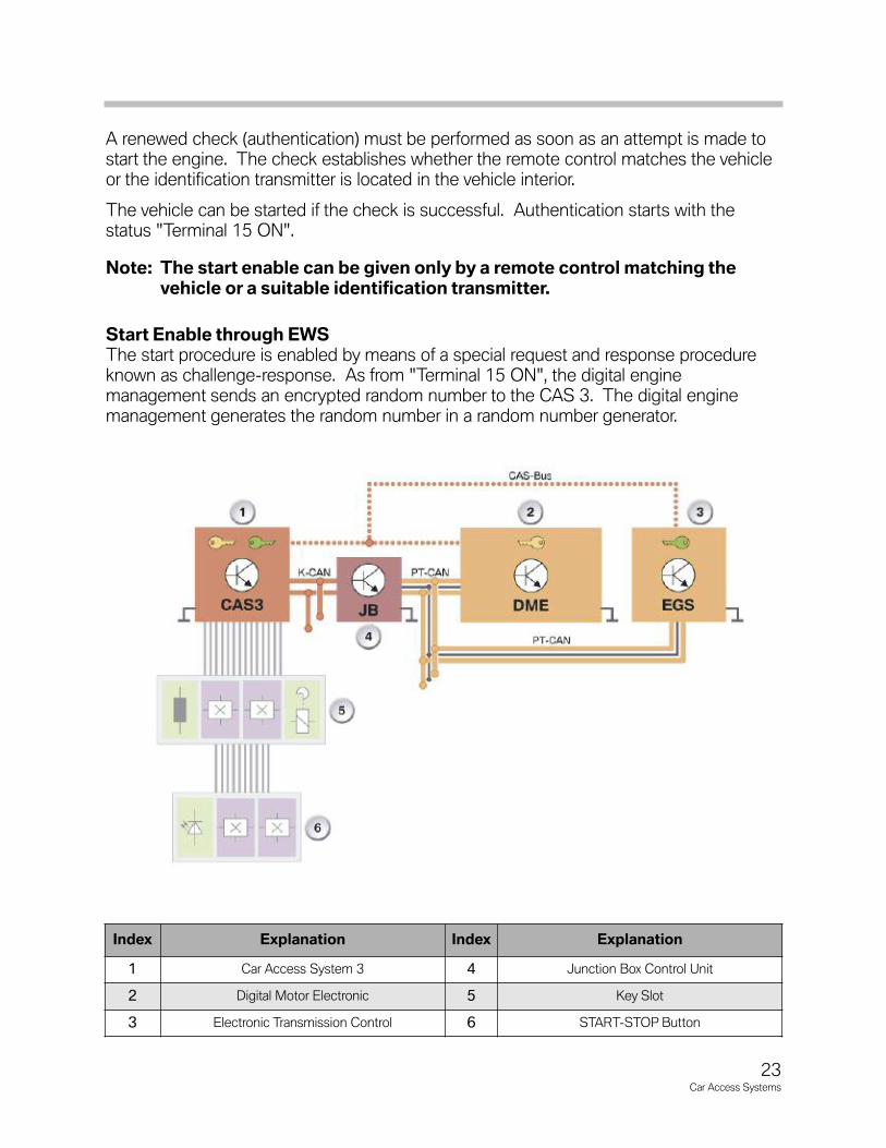
Start Enable through EWSThe start procedure is enabled by means of a special request and response procedureknown as challenge-response. As from "Terminal 15 ON", the digital engine management sends an encrypted random number to the CAS 3. The digital enginemanagement generates the random number in a random number generator.
Index Explanation Index Explanation
1 Car Access System 3 4 Junction Box Control Unit
2 Digital Motor Electronic 5 Key Slot
3 Electronic Transmission Control 6 START-STOP Button
23Car Access Systems
24Car Access Systems
From this random number together with its secret key, the Car Access System calculatesa response and sends it to the digital engine management. In the meantime, the digitalengine management calculates the expected response from the random number with itssecret key.
The Car Access System 3 and the digital engine management use the same secret keyand algorithm for the calculation. The electronic vehicle immobilizer is cancelled if thevalue which the CAS 3 sends to the digital engine management agrees with the valuecalculated by the engine management.
The engine can now be started.
Note: As from "Terminal 15 ON", a cyclic query (challenge-response) is per-formed as long as the engine is not yet running. A fault code is enteredin the CAS 3 if there is no query from the digital engine managementapproximately 10 seconds after the start of the request.
Data Transmission
Data transmission is redundant via the bus systems. The signal from the digital enginemanagement reaches the CAS 3 via the K-CAN and the CAS-Bus. The digital enginemanagement, however, is connected to the PT-CAN. For this reason, the signal is sentvia the gateway of the junction box control unit to the K-CAN. The runtime of the signalsvia the bus systems is of no significance as the signal that reaches the digital enginemanagement first is used for the electronic vehicle immobilizer.
The authentication is repeated in response to following events:
• Transmission and response time exceeded
• Transmission problems
• Response with the secret security code incorrect(e.g. incorrect secret key due to control unit from another vehicle).
Secret KeyThe control units are assigned a secret key on the assembly line. This secret key is generated from a random number. The secret key is valid for a pair of control units andlinked to the specific vehicle. This means that one pair of control units receives the samesecret key. Once the secret key has been entered, the control unit is locked. From thispoint on, the control unit is permanently tied to this secret key and the vehicle. The CAS 3 and the digital motor electronics form one pair of control units.
Note: Since the control units are assigned to the specific vehicle, replacementwith a unit from another vehicle is not possible. When replacing a controlunit, the new control unit must be ordered from BMW. Matching of thecontrol units to each other is no longer necessary.
Gearbox Enable
The enable is based on a procedure similar to that used for EWS 3. As from "Terminal15 ON", the CAS 3 sends encrypted individual codes to the electronic transmission control. The electronic transmission control deciphers and checks these individualcodes. If the check is successful, the gearbox control unit will enable the gearbox functions.
The electronic gearbox control unit forms a pair of control units together with the CAS 3.
Start Value MatchingA start value matching procedure between the CAS 3 and the electronic transmissioncontrol is performed on the assembly line. As part of this procedure, the CAS 3 transfersin encrypted form an individual code to the electronic transmission control.
Consequently, the electronic transmission control knows the individual code and cancheck whether the gearbox functions can be enabled.
25Car Access Systems
Emergency Release
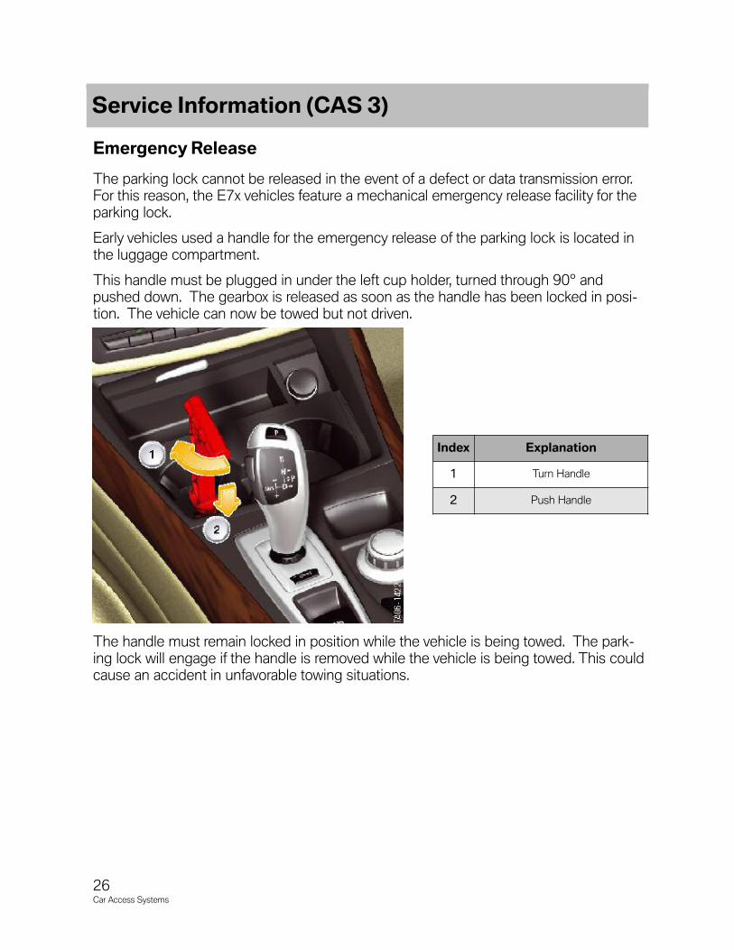
The parking lock cannot be released in the event of a defect or data transmission error. For this reason, the E7x vehicles feature a mechanical emergency release facility for theparking lock.
Early vehicles used a handle for the emergency release of the parking lock is located inthe luggage compartment.
This handle must be plugged in under the left cup holder, turned through 90° andpushed down. The gearbox is released as soon as the handle has been locked in posi-tion. The vehicle can now be towed but not driven.
The handle must remain locked in position while the vehicle is being towed. The park-ing lock will engage if the handle is removed while the vehicle is being towed. This couldcause an accident in unfavorable towing situations.
26Car Access Systems
Index Explanation
1 Turn Handle
2 Push Handle
Service Information (CAS 3)
27Car Access Systems
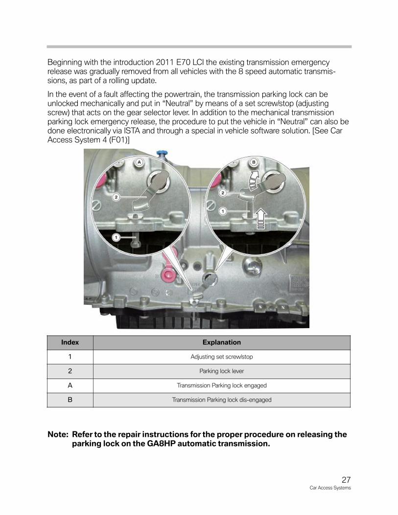
Beginning with the introduction 2011 E70 LCI the existing transmission emergencyrelease was gradually removed from all vehicles with the 8 speed automatic transmis-sions, as part of a rolling update.
In the event of a fault affecting the powertrain, the transmission parking lock can beunlocked mechanically and put in “Neutral” by means of a set screw/stop (adjustingscrew) that acts on the gear selector lever. In addition to the mechanical transmissionparking lock emergency release, the procedure to put the vehicle in “Neutral” can also bedone electronically via ISTA and through a special in vehicle software solution. [See CarAccess System 4 (F01)]
Note: Refer to the repair instructions for the proper procedure on releasing theparking lock on the GA8HP automatic transmission.
Index Explanation
1 Adjusting set screw/stop
2 Parking lock lever
A Transmission Parking lock engaged
B Transmission Parking lock dis-engaged
28Car Access Systems
Vehicle Data Storage (CAS 3)
The Car Access System 3 stores the following vehicle data:
• Personal Profile, the Car Access System 3 stores data for the Personal Profile.
• Vehicle order, the vehicle order is stored in the footwell module.
• Redundant data storage for instrument cluster.
• Data for condition-based service CBS.
• Authentication for diagnosis access to vehicle.
Data for Condition-based ServiceThe data for condition-based service are stored and transferred to the remote control.This data can be read out via the key reader for service purposes. The data for the condition-based service are updated during vehicle operation.
The data in the fault code memory are also updated during vehicle operation.
The conditions are:
• "Terminal 15 ON", Speed above 50 km/h and below 30 km/h.
• The data are updated after covering a distance of 10 km and at a speed below 30km/h.
Manual Update of CBS Data
The procedure for transferring current data to the remote control during servicing is asfollows:
• Insert remote control in its holder.
• Press and hold center-lock button and select "terminal 15 ON" with the START-STOP button.
• After 15 s the CBS data will have been transferred to the remote control.
• Read out remote control.
Manual Update of Fault Memory Data
The procedure for transferring current data to the remote control during servicing is asfollows:
• Press and hold center-lock button.
• Insert remote control in its holder.
• Select "Terminal 15 ON" with the START-STOP button.
• The fault code memory data are transferred to the remote control after 15 seconds.
• Read out remote control.

29Car Access Systems
Control Unit Replacement
A defect in the control units belonging to the EWS represents a challenge for the servicetechnician. Since a defective control unit cannot be replaced by control units from othervehicles particular care is necessary when performing the diagnostic procedure.
A control unit can be ordered through the Parts department. However, it is important tobear in mind that the digital engine electronics (DME) and the CAS 3 are supplied alreadycoded to the vehicle.
This has the advantage that only the control unit is replaced and the matching procedurewith the electronic vehicle immobilizer is not necessary. There is no point in ordering acontrol unit to be kept in stock as the secret key is assigned to the control unit and thevehicle.
A matching procedure is necessary for the electronic transmission control after replacement. As part of this procedure, the CAS 3 transfers the individual code to theelectronic transmission control.
Note: The matching procedure between the CAS3 and electronic transmissioncontrol can take several minutes.

30Car Access Systems
Many Functions, One Control Unit
The Car Access System now features the 4th control-unit generation. Associated withthat is complete integration of the Comfort Access functions in the Car Access System.
The F01 (introduced in 09/08) was the first BMW model be fitted with the Passive Gosystem as standard. Passive Go allows the driver to start the engine without activelyusing the ID transmitter. There is no slot for the ID transmitter on the F0x vehicles.
The ID transmitter only needs to be somewhere inside the passenger compartment forthe engine to be started. The ID transmitter is fitted with a battery. The battery has a lifeof approximately four years.
Up to eight ID transmitters can be used for a particular vehicle. Four of the eight IDtransmitters can be used for personal profiles.
Index Explanation Index Explanation
1 ID transmitter, top view 6 ID Transmitter, rear view
2 Unlock vehicle button 7 Location of emergency start coil
3 Lock vehicle button 8 Battery compartment
4 Unlock luggage compartment button 9 Release button for mechanical key
5
Panic alarm andheadlight courtesy delay feature or
open large trunk lid (F07) orIndependent A/C system on (F04)
10 Mechanical key
Car Access System 4 (F01)

31Car Access Systems
Input/Output - Car Access System 4
The Car Access System 4 (2) is responsible for terminal control. For instance "Terminal15 ON" is made available to the intelligent battery sensor (4). The terminal statuses, e.g."Terminal 15 ON/Terminal 0", can be selected by means of the START-STOP button(11). In conjunction with the digital motor electronics (3), the Car Access System 4issues the start enabling signal for the starter motor (5).
Index Explanation Index Explanation
1 Hood switch 11 START-STOP button
2 Car Access System 4 (CAS 4) 12 Center-lock button
3 Digital motor electronics (DME) 13 Brake light switch (BLS)
4 Intelligent battery sensor (IBS) 14 Dynamic Stability Control (DSC)
5 Starter 15 Central double-locking button
6 Junction box module 16 Interior tailgate button, A- pillar
7 Identification transmitter CAS-Bus CAS-Bus
8 Terminal 15 K-CAN Bodyshell CAN
9 Electronic outer door handle module (TAGE) PT-CAN Powertrain CAN
10 Telematics control unit (TCU)
System Overview

32Car Access Systems
System Circuit Diagram - CAS 4

Legend for System Circuit Diagram - CAS 4
33Car Access Systems
Index Explanation Index Explanation
1 Hood switch 20Remote control receiver in
diversity module (DIV)
2 Dynamic Stability Control (DSC) 21 Hotel setting switch
3 Central Gateway Module (ZGM) 22 Comfort Access interior antenna
4 Electronic transmission control (EGS) 23 START-STOP button
5 Starter 24 Emergency start coil (transponder coil)
6 Digital motor electronics (DME) 25 Car Access System 4 (CAS 4)
7 Integrated Chassis Management (ICM) Kl. 15_1 Terminal 15 (output 1)
8Junction box module (JB) and
front power distribution boxKl. 15_3 Terminal 15 (output 3)
9 Luggage compartment power distribution box Kl. 15 WUP Terminal 15, wake-up
10 Tailgate central double-locking button Kl. 15N Terminal 15N (Overrun)
11 Telephone control unit (TCU) Kl. 30 Terminal 30
12 Interior tailgate button, A- pillar Kl. 30B Terminal 30B, switched
13 Instrument cluster (KOMBI) Kl. 50L Terminal 50 load
14 Steering column switch cluster CAS-Bus CAS-Bus
15 Center-lock button/ hazard warning switch LIN-Bus Local Interconnect Network bus
16 Brake light switch (BLS) K-CAN2 Body CAN2
17 Footwell module (FRM) PT-CAN Powertrain CAN
18 Crash Safety Module (ACSM) A_S_ START Start/start termination DME
19 Comfort Access interior antenna
34Car Access Systems
Function Overview
The Car Access System 4 provides, among other things, the central control unit for vehicle access and vehicle locking. Consequently, the Car Access System 4 has complete control over central locking. The Car Access System 4 has sole knowledgeof the system and decides whether, for instance, to allow access to the vehicle or not. In other words, whether to unlock the vehicle or not. That function is referred to as amaster function.
The Car Access System 4 incorporates the following master functions:
• Comfort Access
• Central locking
• Power windows
• Sliding/tilting sunroof
• Terminal control
• Electronic immobilizer 4
Other functions of the Car Access System 4 include:
• Vehicle data storage
• Data transmission for Conditioned Based Service (CBS)
• Checking plausibility of remote control signals.
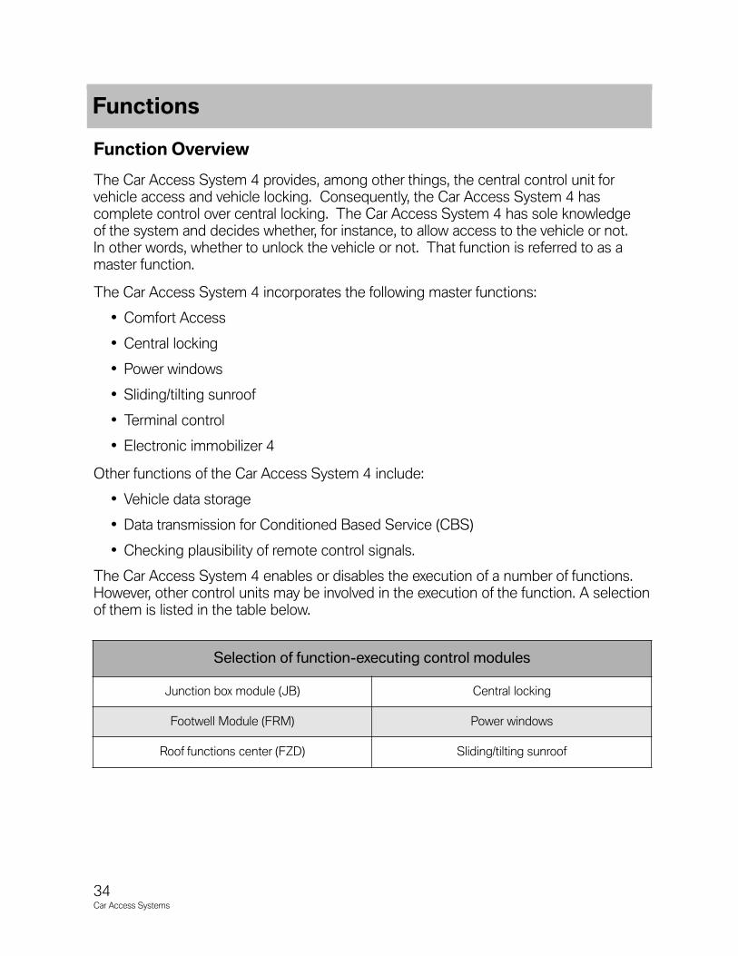
The Car Access System 4 enables or disables the execution of a number of functions.However, other control units may be involved in the execution of the function. A selectionof them is listed in the table below.
Selection of function-executing control modules
Junction box module (JB) Central locking
Footwell Module (FRM) Power windows
Roof functions center (FZD) Sliding/tilting sunroof
Functions

35Car Access Systems
For the purposes of communication with other electrical-system devices, the Car AccessSystem 4 is connected to the K-CAN2, CAS bus and LIN bus.
The Car Access System 4 analyzes the status of the hood switch and broadcastsit for use by the alarm system. It also analyzes the status of the following buttons andinitiates the central locking function.
• Center Lock button, locking/unlocking central locking
• Interior tailgate button on A-pillar, unlocking tailgate
• Central double-locking button, locking and double-lockingvehicle doors using button on underside of open tailgate
• Hotel setting switch, preventing tailgate unlocking function.
The Car Access System 4 provides the power supply for the brake light switch and alsoanalyzes its status.
The sections that follow describe some of the functions of the Car Access System.Those functions are:
• Terminal control
• Electronic immobilizer
• Gearbox enable
• Vehicle data storage
36Car Access Systems
Terminal Control (CAS 4)
The Car Access System 4 provides the terminal status information for the other electri-cal-system devices. It does so by broadcasting the terminal status signal on the K-CAN2or by directly switching the terminal concerned on/off.
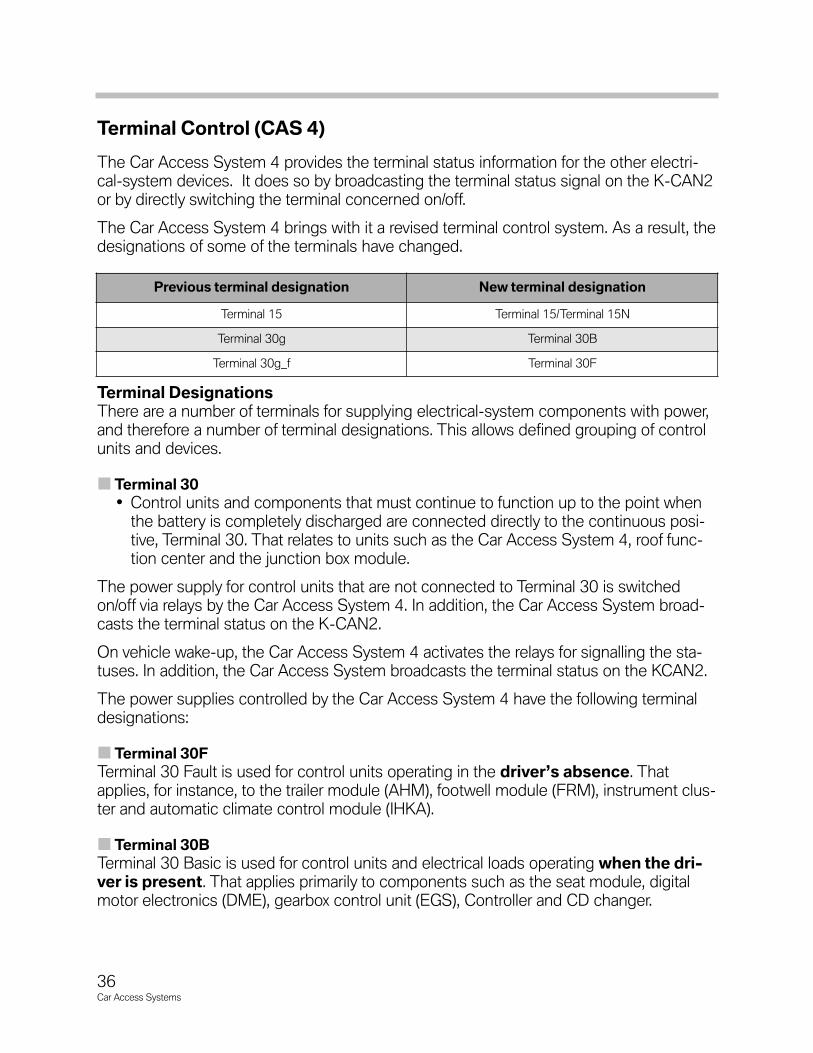
The Car Access System 4 brings with it a revised terminal control system. As a result, thedesignations of some of the terminals have changed.
Terminal Designations There are a number of terminals for supplying electrical-system components with power,and therefore a number of terminal designations. This allows defined grouping of controlunits and devices.
Terminal 30
• Control units and components that must continue to function up to the point whenthe battery is completely discharged are connected directly to the continuous posi-tive, Terminal 30. That relates to units such as the Car Access System 4, roof func-tion center and the junction box module.
The power supply for control units that are not connected to Terminal 30 is switchedon/off via relays by the Car Access System 4. In addition, the Car Access System broad-casts the terminal status on the K-CAN2.
On vehicle wake-up, the Car Access System 4 activates the relays for signalling the sta-tuses. In addition, the Car Access System broadcasts the terminal status on the KCAN2.
The power supplies controlled by the Car Access System 4 have the following terminaldesignations:
Terminal 30F
Terminal 30 Fault is used for control units operating in the driver’s absence. Thatapplies, for instance, to the trailer module (AHM), footwell module (FRM), instrument clus-ter and automatic climate control module (IHKA).
Terminal 30B
Terminal 30 Basic is used for control units and electrical loads operating when the dri-ver is present. That applies primarily to components such as the seat module, digitalmotor electronics (DME), gearbox control unit (EGS), Controller and CD changer.
Previous terminal designation New terminal designation
Terminal 15 Terminal 15/Terminal 15N
Terminal 30g Terminal 30B
Terminal 30g_f Terminal 30F

37Car Access Systems
Note: The relay for Terminal 30F is located in the front power distribution boxand the rear power distribution box.
Terminal 15
Terminal 15 is used to signal the status “Ignition ON/Ignition OFF” rather than as a powersupply. That applies, for instance, in the case of the digital motor electronics (DME), thefootwell module (FRM) and BMW Night Vision.
Terminal 15N
Terminal 15 N (Overrun) is used for control units and electrical loads operating at status“Ignition ON” when the vehicle is being driven. That applies, for instance, to the lanedeparture warning (SWW), short range radar (SRR) and Night Vision.
Note: The relay for Terminal 15N is located in the front power distribution boxand the rear power distribution box.
Terminal 15WUP
Terminal 15 Wake-up is used to wake up control units that can not be woken upby bus communication.
Terminal 50
Terminal 50 is provided for controlling the starter motor.
38Car Access Systems
Terminal 30 Fault If Terminal 30F has been switched off dueto an electrical system fault, for instance, itis switched on together with the othercomponents at vehicle wake-up.
The conditions that result in Terminal 30Fbeing switched on are:
• Requests for ID transmitter e.g.Comfort Access due to request fromexterior door handle module.
• Unlocking central locking Lockingcentral locking Double-locking cen-tral locking.
• START-STOP button pressed.
• Bus activity e.g. demand for powersupply to a part of the electrical sys-tem.
• Power reset if the conditions forswitching on are met after a powerreset.
If a vehicle can not switch to sleep modedespite the power reset, Terminal 30F isswitched off.
If electrical consumers such as side lights,parking lights or hazard warning lights areswitched on, Terminal 30F can neverthe-less be switched off.
Switch-off inhibitors
Terminal 30F can not be switched off atstatus Terminal 30B ON. That preventscontrol units or electrical devices beingswitched off during basic-mode operationof the vehicle.
Switch-off of Terminal 30F is also prevent-ed if a terminal status is implausible.
The relay contacts for Terminal 30F aremonitored. If the contacts stick, it preventsthe relay for Terminal 30F switching off.
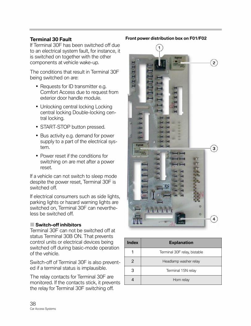
Index Explanation
1 Terminal 30F relay, bistable
2 Headlamp washer relay
3 Terminal 15N relay
4 Horn relay
Front power distribution box on F01/F02
39Car Access Systems
Switching Off Terminal 30F
If the Car Access System has switched off Terminal 30B, then Terminal 30F can beswitched off if the battery upper starting capacity limit is reached. Terminal 30F can beswitched off after a power reset has been carried out. Additional conditions must also bemet, however. Those conditions are:
• Additional bus wake-ups at least ten bus wake-ups
• Unexplained bus activity
• Closed-circuit current too high.
If the vehicle is in transport mode status, then, if possible, Terminal 30F is switched off.
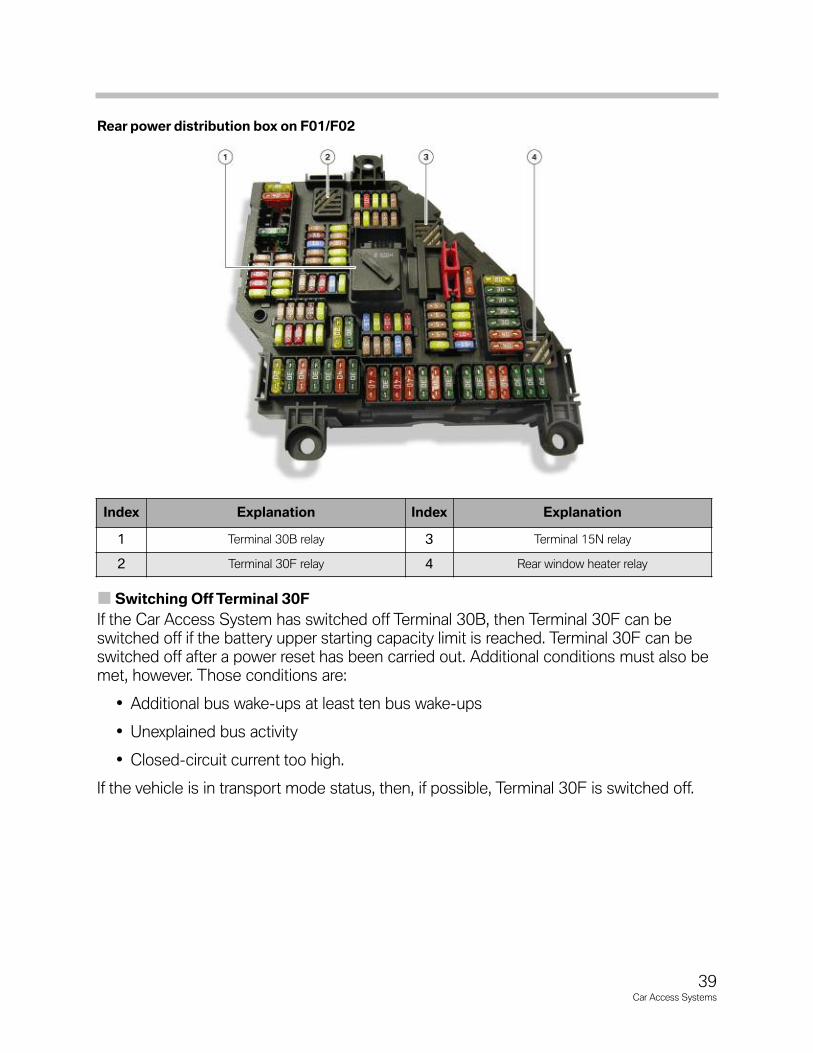
Index Explanation Index Explanation
1 Terminal 30B relay 3 Terminal 15N relay
2 Terminal 30F relay 4 Rear window heater relay
Rear power distribution box on F01/F02

40Car Access Systems
Terminal 30 Basic
The conditions that result in Terminal 30B being switched on are:
• Requests for ID transmitter e.g. Comfort Access due to request from exterior doorhandle module.
• Unlocking central locking Locking central locking Double-locking central locking.
• START-STOP button pressed.
• Bus activity e.g. demand for power supply to a part of the electrical system.
• Change of door-switch status Change of tailgate switch status.
Switching Off Terminal 30B
When the vehicle is locked, the Car AccessSystem receives the central double-lockingsignal. Once the vehicle is locked, Terminal30B remains on for approx. one minute and isthen switched off by the Car Access System.The tailgate must have already been closed.
If the vehicle is not locked or if the tailgateremains open, the delay until Terminal 30B isswitched off is approx. 30 minutes. After that,the Car Access System switches Terminal30B off.
In addition, Terminal 30B can be switched offwhen the vehicle is in parked mode if the bat-tery upper starting capacity limit is reached.
During fault diagnosis, the power down com-mand can be used to switch off Terminal 30Bunder defined conditions for the purposes ofmeasuring quiescent current.
If the vehicle is in transport mode status, Terminal 30F is switched off.
Terminal 15 After Terminal 30 is switched on, the Car Access System 4 signals the status of Terminal15 by switching on the power supply or broadcasting it via the K-CAN2.
Direct power supply from Terminal 15 has the advantage that the control units continue tobe supplied from Terminal 15 even if terminal status messages are not received within abus system, for example. In that way, emergency-mode functions can be maintained onthe basis of terminal status if necessary.
Index Explanation
1 Terminal 30B relay
41Car Access Systems
Note: Driver output stages are integrated in the Car Access System for thepurpose of switching on Terminal 15. The Car Access System has threeoutputs for the status of Terminal 15.
The following control units receive the Terminal 15 status signal directly:
Those control units are:
• Driver’s-side footwell module, FRM
• Crash Safety Module, ACSM
• Instrument cluster, KOMBI
• Digital engine management module, DME
• Central Gateway Module, ZGM
• Electronic transmission control EGS
• Steering column switch cluster, SZL
• Integrated Chassis Management, ICM
Switching Off Terminal 15
Terminal 15 can be switched off by pressing the START-STOP button, a change ofstatus to Terminal 0.
Terminal 15 is automatically switched off if the following conditions occur:
• Vehicle double-locked by double-lock command.
• Battery reaching upper starting capacity limit.
• Car-wash special mode, switch-off takes place after 15 or 30 minutes.
Switch-off inhibitors
Automatic switching off of Terminal 15 may be prevented if the following conditionsoccur:
• Vehicle is moving, road-speed signal.
• Engine running.
• Brake pedal operated.
• Gear selector lever in position N, time-limited for special Car Wash mode.
• Low beam headlights ON Not when vehicle double-locked.
• Vehicle in transport mode status when coding in progress.
• Communication with the OBD.
• Switch-off inhibitor diagnosis.

42Car Access Systems
Terminal 15N Terminal 15N is switched on via a relay by theCar Access System. There is a relay fitted bothin the front and rear power distribution boxesfor the purpose.
Relay for Terminal 15N
The control modules connected to Terminal15N are connected to the vehicle power sup-ply shortly after Terminal 15 is switched on.
Switching Off Terminal 15N
Before Terminal 15 is switched off, the controlmodules that are connected to Terminal 15Nare notified that Terminal 15N is to beswitched off.
After Terminal 15 is switched off, the controlunits connected to Terminal 15N have five seconds time to save their data. After thosefive seconds have elapsed, the Car AccessSystem 4 switches the relay off. At that point,the control modules concerned are switchedoff under defined conditions.
Note: The notification that Terminal 15N is to be switched off can only bereceived by control units or components that are connected to a bussystem.
Functional Reliability of Switchable Terminals
In order to increase the functional reliability of the vehicle's power supply, Terminal 30F,Terminal 30B and Terminal 15N can not be switched off under the following conditions:
• Terminal 15 ON
• Vehicle moving
• Engine running
The Car Access System has two processors that are responsible for terminal control. The software on the main processor and coprocessor prevents undefined switch-off ofTerminal 15 and switch-on of Terminal 50.
Terminal 30F is safeguarded by the status of Terminal 30B. That means that whenTerminal 30B is on, Terminal 30F can not be switched off.
Index Explanation
1 KL15 N relay, soldered
Front power distribution box on F01/F02
43Car Access Systems
ID Transmitter Search in Passenger CompartmentWhen the START-STOP button is pressed, it triggers the search for an ID transmitter inthe passenger compartment. The passenger compartment search is required for thePassive Go function in order that starting can be enabled.
When performing the passenger compartment search, the Car Access System 4 issues arequest for an ID transmitter to register with the vehicle.
There are two antennas provided for the passenger compartment search. One antennacovers the front of the passenger compartment and the other the rear. The antennas areconnected to the Car Access System 4.
The Car Access System 4 sends out a signal with a frequency of 125 KHz through theantennas. That signal triggers the ID transmitter to register with the vehicle.
The ID transmitter responds with an encrypted radio signal. The remote control receiverin the diversity module passes the radio signal information to the Car Access System 4via the LIN bus.
The Car Access System checks whether the ID transmitter belongs to the vehicle.
Subsequent communication takes place on the ID transmitter’s transmission frequency,e.g. 315 MHz.
The Car Access System 4 checks whether the ID transmitter matches the vehicle. If thecheck is positive, the Car Access System 4 enables terminal control. The individual terminals can then be selected.
Note: If communication with the ID transmitter can not be established, a CheckControl message is displayed on the instrument cluster. The driver isnotified that no ID transmitter could be located inside the passengercompartment.
The ID transmitter can be held in the position marked on the steeringcolumn. There is an emergency start coil under the steering column trim.Communication between the Car Access System 4 and the ID transmit-ter can be established via the emergency start coil. More detailed infor-mation on this subject can be found in the description of the emergencystart coil component.
44Car Access Systems
Terminal Selection
Briefly pressing the START-STOP button cycles through the terminal statusesin the following order:
• Terminal 0
• Terminal 15
• Terminal 0
• Terminal 15
Note: On automatic vehicles, selecting the statuses in that order is onlypossible if the brake pedal is not depressed.
As soon as the brake pedal is pressed, the engine will start the next time theSTARTSTOP button is pressed.
Terminal 0 is a logical terminal and does not provide a power supply.Terminal 0 comprises Terminal 30, Terminal 30B and Terminal 30F.
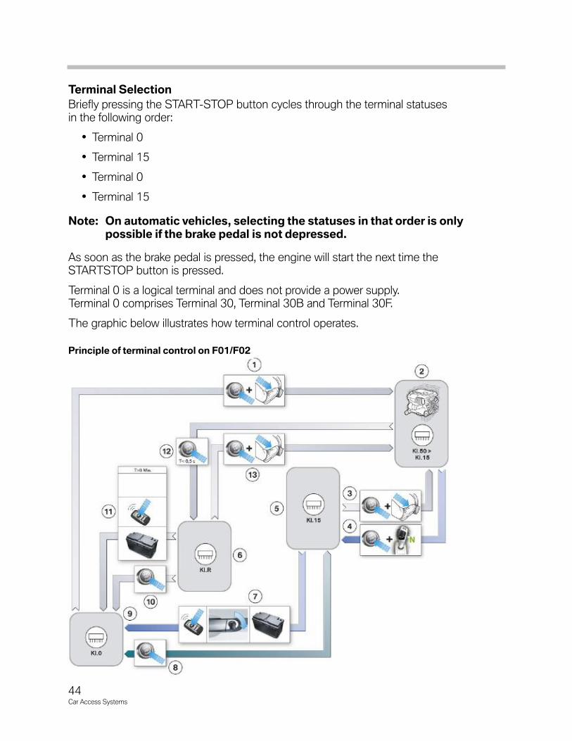
The graphic below illustrates how terminal control operates.
Principle of terminal control on F01/F02

Legend for principle of terminal control on F01/F02
45Car Access Systems
Index Explanation Index Explanation
1 START-STOP button + (brake pedal operated) 8Central double-locking, driver's door lock,
upper starting capacity limit reached
2 Engine running (Terminal 50 > Terminal 15) 9 Off (Terminal 0)
3 START-STOP button + (brake pedal operated) 10 START-STOP button, SST
4 SST + selector position "N" (car wash) 118 minutes central double-locking
upper starting capacity limit reached
5 Ignition (Terminal 15) 12 SST briefly pressed
6 Radio (Terminal R) 13 START-STOP button + (brake pedal operated)
7Central double-locking, driver's door lock,
upper starting capacity limit reached
46Car Access Systems
Washing the vehicle in a car wash
A new feature of the function for washing the car in a car wash is that, under certain cir-cumstances, the status Terminal 15 ON is maintained for at least 15 minutes.
The conditions for that are:
• Gear selector lever in position “N”
• Engine stopped by START-STOP button
A timer on the Car Access System 4 is started and maintains the status Terminal 15 ONfor a period of 15 minutes. If the vehicle is moved during that period, the period for whichTerminal 15 ON is upheld is extended by a further 15 minutes. The maximum period forthe function is limited to 30 minutes. In that way, the vehicle’s battery is saved and notunnecessarily discharged.
Note: When Terminal 15 is switched off, the gear selector lever is automaticallymoved to position P.
Movement of the vehicle is detected by means of the signals from the wheel speed sensors. The Dynamic Stability Control (DSC) registers the wheel speed sensor signals,while the Integrated Chassis Management makes the road-speed signal available to theelectrical system.
A Check Control message for the driver is displayed on the instrument cluster indicatingthat the vehicle is capable of moving and can not be locked from the outside. In addition,attention is drawn to the situation by an audible gong signal.
If, for instance, the driver attempts to lock the vehicle using the ID transmitter, permissionis denied. Instead, the horn is sounded to draw attention to the fact that the vehicle hasnot been locked.
Terminal R
The status Terminal R ON can only be selected if the engine has been stopped by brieflypressing the START-STOP button.
The status Terminal R ON/Terminal R OFF is purely a bus signal. The Car Access Systembroadcasts the signal on the K-CAN2. Consequently, the F01/F02 does not have a sepa-rate lead for Terminal R!
Terminal R is switched off under the following conditions:
• START-STOP button pressed
• Vehicle double-locked by double-lock command
• Time limit of 8 minutes not exceeded
• Battery upper starting capacity limit reached
47Car Access Systems
Electronic Immobilizer 4
The electronic vehicle immobilizer 4 is an immobilizer system that prevents unauthorizedengine start. The immobilizer was first introduced with the Car Access System 3 on theE92 and the latest version is a derivation of that design.
Design of the Electronic Vehicle Immobilizer EWSThe vehicle immobilizer consists of the identification transmitter which identifies itself tothe vehicle and therefore to the Car Access System 4. The Car Access System 4exchanges data via the CAS bus with the digital motor electronics in order to cancel theimmobilizer function.
Note: The ID transmitter also has to identify itself to the vehicle and, therefore,to the Car Access System 4.
The software for the electronic immobilizer and for enabling engine starting is incorporat-ed in the Car Access System 4. Enabling of ignition and fuel injection is the responsibilityof the digital motor electronics.
Before the electronic immobilizer issues the enabling signal for starting, the ID transmittermust be identified as matching the vehicle. As soon as an attempt is made to start theengine, a check (authentication) has to be carried out.
That check establishes whether a matching ID transmitter is located in the passengercompartment. The vehicle can be started if the check is successful. Authentication starts with the status “Terminal 15 ON”.
Note: The time taken to search for an ID transmitter in the passenger compart-ment may result in a delay before engine starting is enabled. That delaymay occur in a time span of up to half a second.

48Car Access Systems
Start Enable Through the Electronic Vehicle ImmobilizerThe start procedure is enabled by means of a special request and response procedureknown as challenge-response.
As of “Terminal 15 ON”, the digital motor electronics sends an encrypted random num-ber to the Car Access System 4. The digital motor electronics uses a random numbergenerator to generate the random number.
On the basis of that random number and its secret key, the Car Access System 4 calcu-lates a response and sends it to the digital motor electronics. In the meantime, the digitalmotor electronics calculates the expected response from the random number and itssecret key.
The Car Access System 4 and the digital motor electronics use the same secret key andalgorithm for the calculations.
If the figure that the Car Access System 4 sends to the digital motor electronics matchesthe figure calculated by the motor electronics, the electronic immobilizer is deactivated.
The engine can now be started.
Note: As from “Terminal 15 ON”, a cyclic query (challenge-response) is per-formed as long as the engine is not yet running.
Data transmission
Data transmission is redundant via the bus systems.
Index Explanation Index Explanation
1 Car Access System 4 (CAS 4) 4 Electronic transmission control unit
2 Central Gateway Module 5 START-STOP button
3 Digital Motor Electronics (DME) 6 Transponder coil (emergency start coil)
Duplicated data transmission on F01/F02

49Car Access Systems
The signal from the digital motor electronics, for instance, reaches the Car AccessSystem 4 via both the K-CAN2 and the CAS bus. The digital motor electronics, however,is connected to the PT-CAN. For that reason, the signal is transferred from PT-CAN tothe K-CAN2 by the central gateway module. The time taken by the signals via the differ-ent bus systems is of no consequence as the signal that reaches the digital motor elec-tronics first is used for the electronic immobilizer.
The authentication is repeated in response to following events:
• Transmission and response time exceeded
• Transmission problems
• Response with the secret security code incorrect (e.g. incorrect secret key due tocontrol unit from another vehicle).
Secret key
The control units are assigned a secret key on the assembly line. This secret key is generated from a random number. The secret key is valid for a pair of control units andlinked to the specific vehicle. This means that one pair of control units receives the samesecret key. Once the secret key has been entered, the control unit is locked. From thispoint on, the control unit is permanently tied to this secret key and the vehicle. The Car Access System 4 and the digital motor electronics form a control unit pairing.
Note: Since the control units are assigned to the specific vehicle, replacementwith a unit from another vehicle is not possible. When replacing a controlunit, the new control unit must be ordered from BMW. Matching of thecontrol units to each other is no longer necessary.

50Car Access Systems
Gearbox Enable
The enable is based on a procedure similar to that used for the electronic vehicle immo-bilizer 3.
As of “Terminal 15 ON”, the Car Access System 4 sends encrypted individual codes tothe transmission control unit. The signal is applied to the PT-CAN2 by the digital motorelectronics.
The electronic transmission control deciphers and checks these individual codes. If thecheck is successful, the gearbox control unit will enable the gearbox functions.
The electronic gearbox control unit forms a pair of control units together with the CarAccess System 4.
Start Value Matching A start value matching procedure between the Car Access System 4 and the electronictransmission control is performed on the assembly line. That involves the Car AccessSystem 4 transferring an encrypted individual code to the transmission control unit.Consequently, the electronic transmission control knows the individual code and cancheck whether the gearbox functions can be enabled.
Emergency Release of Parking LockThe parking lock cannot be released in the event of a defect or data transmission error.For that reason, the F0x vehicles feature a mechanical emergency release facility for theparking lock.
Early vehicles used handle for the emergency releaseof the parking lock is located in the luggage compart-ment. That handle must be inserted in the slot at thebottom of the cup holder, turned through 90° andpushed down.
The gearbox is released as soon as the handle hasbeen locked in position.The vehicle can now be towedbut not driven.
Note: The handle must remain locked in position while the vehicle is beingtowed. The parking lock will engage if the handle is removed while thevehicle is being towed. This could cause an accident in unfavorable tow-ing situations.
Index Explanation
1 Turn handle
2 Press handle downReleasing parking lock on F01/F02
51Car Access Systems
Beginning with the introduction 2011 E70 LCI the existing transmission emergencyrelease was gradually removed from all vehicles with the 8 speed automatic transmis-sions, as part of a rolling update. [See Car Access System 3 (E70)]
In the event of a fault affecting the powertrain, the transmission parking lock can beunlocked mechanically and put in “Neutral” by means of a set screw/stop (adjustingscrew) that acts on the gear selector lever. In addition to the mechanical transmissionparking lock emergency release, the procedure to put the vehicle in “Neutral” can also bedone electronically via ISTA and through a special in vehicle software solution.
How to release the parking lock electronically in case the vehicle does not start:
• Activate ignition.
• Press the brake pedal and continue pressing it throughout all further steps .
• Press start/stop-button.
• As soon as you notice the starter motor has engaged, press the unlock-button of thegearshift and move forward to position N (please note: for models with dieselengines and at low ambient temperatures a delay of 4 seconds is to be expected).Continue to hold the gearshift in this position up to the sound of the CC-message-gong which indicates the message of “gearbox dysfunction” – now please releasethe gearshift.
How to release the parking lock electronically:
• Reselect gear-position N within a timeframe of 6 seconds (repeat step 4 of theinstructions). Gear-position N is then displayed on the instrument display.
• Please continue pressing the brake pedal until the starter-motor stops, then thebrake-pedal can be released and the vehicle can be moved to the desired position.
• The ignition must remain activated at all times. In case of switching off the ignition,the gear position P is automatically engaged.
• In cases where the N selection cannot be achieved, first switch on the ignition andthen off. (Press start/stop-button several times without pressing the brake pedal). Youmay then retry the process following the steps 1-7. If after 3 attempts N cannot beselected please wait a minimum of 10 minutes in order to allow the starter motor tocool down.
The vehicle can only be moved manually. Towing the vehicle is advised since the parkinglock could engage and be damaged.
CAUTION!!!
52Car Access Systems
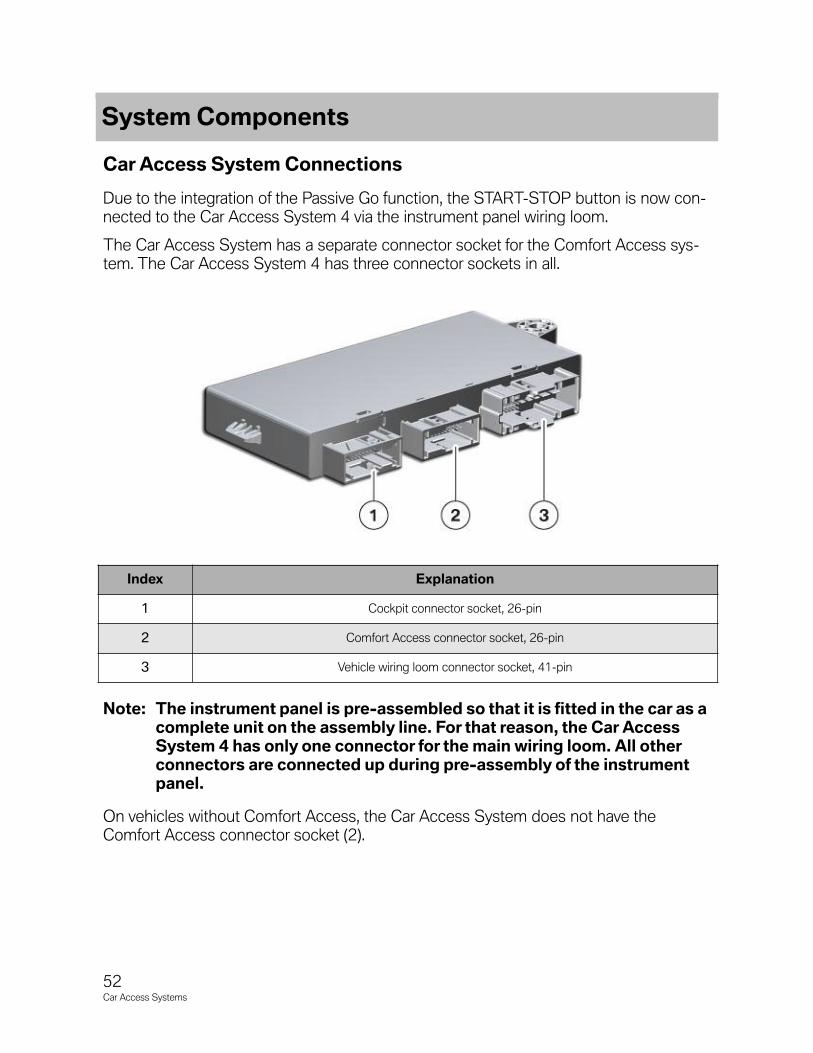
Car Access System Connections
Due to the integration of the Passive Go function, the START-STOP button is now con-nected to the Car Access System 4 via the instrument panel wiring loom.
The Car Access System has a separate connector socket for the Comfort Access sys-tem. The Car Access System 4 has three connector sockets in all.
Note: The instrument panel is pre-assembled so that it is fitted in the car as acomplete unit on the assembly line. For that reason, the Car AccessSystem 4 has only one connector for the main wiring loom. All otherconnectors are connected up during pre-assembly of the instrumentpanel.
On vehicles without Comfort Access, the Car Access System does not have theComfort Access connector socket (2).
Index Explanation
1 Cockpit connector socket, 26-pin
2 Comfort Access connector socket, 26-pin
3 Vehicle wiring loom connector socket, 41-pin
System Components

53Car Access Systems
Other Components
START-STOP Button The START-STOP button is integrated in the instrument panel. In contrast with the previ-ous connection, the ribbon cable has been dispensed with. The necessary leads for con-necting the START-STOP button are now integrated in the wiring loom for the instrumentpanel.
The START-STOP button is illuminated by an LED as of status Terminal 58g ON(KL58g).
Emergency Start Coil In unfavorable situations, the system may not be able to find the ID transmitter in the passenger compartment. For that reason, the Car Access System initiates display of amessage on the instrument cluster. The message notifies the driver that no ID transmit-ter could be located inside the passenger compartment.
Since the F01/F02 does not have a slot for the ID transmitter, there is an emergency startcoil on the steering column. The emergency start coil can be used to communicate withthe ID transmitter so that the engine can still be started and the vehicle driven.
The emergency start coil is equivalent to the function of the transponder coil. By commu-nicating via the transponder coil, the Car Access System 4 is able to identify a valid IDtransmitter. Thus the Car Access System 4 is able to issue the start enabling signal following successful identification.
In the following situations, for example, the system may not be able to find the ID transmitter:
• ID transmitter defective
• Interference with radio transmission to ID transmitter
• Discharged battery in ID transmitter
Index Explanation
1 Emergency start coil

54Car Access Systems
Remote Control Receiver The remote control receiver now has a transmitter and receiver unit and is integrated inthe diversity module. As a result, bidirectional communication can be establishedbetween the ID transmitter and the remote-control receiver.
The remote control receiver now also has a LIN bus connection. The remote controlreceiver use that LIN bus connection to wake up the Car Access System 4. In that case,the Car Access System 4 asks the remote control receiver if there is a message waiting.
That message may contain a request to unlock the vehicle. The Car Access Systemchecks, for instance, whether the ID transmitter belongs to the vehicle. If the check ispositive, the Car Access System 4 initiates unlocking of the vehicle.
Note: As a LIN-Bus device, the remote control receiver is an input capableof waking up the Car Access System 4.
Input Components The Car Access System 4 analyzes buttons for the central locking functions. All buttonsconnect to earth. That means that the Car Access System 4 receives a low signal whenthe button is pressed.
The buttons concerned are:
• Center-lock button
• Interior tailgate button on A- pillar
• Central double-locking button on underside of tailgate
• Hotel setting switch
• Hood switch (alarm system)

55Car Access Systems
Vehicle Data Storage
The Car Access System 4 stores the following vehicle data:
• Personal Profile, the Car Access System 4 stores data for the Personal Profile
• Vehicle order, the vehicle order is stored in the footwell module
• Redundant data storage for instrument cluster
• Data for condition-based service CBS
• Service key data (e.g. data for Condition Based Service, fault memory entries,Check Control messages, etc.)
• Authentication for diagnostic access to the Car Access System 4
The Car Access System’s temporary memory permanently stores data such as theCondition Based Service version, the vehicle identification number (VIN), software ver-sion, etc.
The Car Access System receives current data from the electrical system, such as out-side temperature, engine temperature, date, time and odometer reading, via the K-CAN2. The Car Access System collects that information. Under certain conditions, thedata is transferred to the ID transmitter. In that way, the service key data is kept up to datefor readout when the vehicle is taken in for servicing.
Service Information (CAS 4)

56Car Access Systems
Updating Service Data The service data records and fault memory entries are collected in a temporary memoryby the Car Access System. The service data is thus available from a central point.
If one of the conditions set out below results in transfer of the service key data, the ser-vice key data on the ID transmitter is updated.
Note: Updating can be performed both by way of the emergency start coil’slow frequency signal (5) and by means of the transmission frequencyused by the ID transmitter (6).
Updating Service Key Data The service key data is stored in the Car Access System and transferred to the ID trans-mitter. Transfer is initiated automatically by specific conditions or manually. The data canbe read out using the BMW Key Reader when the vehicle is serviced.
Automatic updating
The service key data is updated every time the vehicle is driven. That data comprises:
• Conditioned Based Service data
• Check Control messages
• Fault memory entries
Index Explanation
1 Car Access System
2Current data on electrical system that Car
Access System receives via K-CAN2
3Diagnosis data via K-CAN2 or direct from
Car Access System
4Permanently stored data provided by Car
Access System
5Manual data transfer (emergency start coil,
low frequency)
6Automatic updating of data (transmission
frequency of ID transmitter, high frequency)
µCAccumulated data in Car Access System’s
temporary memory
ID transmitter updating principle
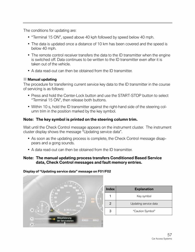
57Car Access Systems
The conditions for updating are:
• “Terminal 15 ON”, speed above 40 kph followed by speed below 40 mph.
• The data is updated once a distance of 10 km has been covered and the speed isbelow 40 mph.
• The remote control receiver transfers the data to the ID transmitter when the engineis switched off. Data continues to be written to the ID transmitter even after it istaken out of the vehicle.
• A data read-out can then be obtained from the ID transmitter.
Manual updating
The procedure for transferring current service key data to the ID transmitter in the courseof servicing is as follows:
• Press and hold the Center-Lock button and use the START-STOP button to select“Terminal 15 ON”, then release both buttons.
• Within 10 s, hold the ID transmitter against the right-hand side of the steering col-umn trim in the position marked by the key symbol.
Note: The key symbol is printed on the steering column trim.
Wait until the Check Control message appears on the instrument cluster. The instrumentcluster display shows the message “Updating service data”.
• As soon as the updating process is complete, the Check Control message disap-pears and a gong sounds.
• A data read-out can then be obtained from the ID transmitter.
Note: The manual updating process transfers Conditioned Based Servicedata, Check Control messages and fault memory entries.
Index Explanation
1 Key symbol
2 Updating service data
3 “Caution Symbol”
Display of “Updating service data” message on F01/F02
58Car Access Systems
Control Unit Replacement
As is the case with the CAS 3 system, a defect in the control units belonging to the EWSrepresents a challenge for the service technician. Since a defective control unit cannotbe replaced by control units from other vehicles particular care is necessary when per-forming the diagnostic procedure.
A defective control unit can be ordered through parts department. However, it is impor-tant to bear in mind that the digital motor electronics (DME) and the Car Access System4 are supplied already-coded for the vehicle.
This has the advantage that only the control unit is replaced and the matching procedurewith the electronic vehicle immobilizer is not necessary.
There is no point in ordering a control unit to be kept in stock as the secret key isassigned to the control unit and the respective vehicle.
A matching procedure is necessary for the electronic transmission control after replace-ment. As part of this procedure, the Car Access System 4 transfers the individual codeto the electronic transmission control.
Note: The matching procedure between the CAS 4 and a new electronic trans-mission control can take several minutes.
Note: For more service information regarding the Car access System refer toFTD-ANL-SBT2003-610303019_H1 General information for servicestaff on CAS and always refer to the repair instructions.

![เรียน-เล่น-เป็นง่าย Access 2007 · Microsoft Access Microsoft Office Professional Access "adî... Access Access Access "îl]î" muùouañoo:ls Access](https://static.fdocuments.us/doc/165x107/5f5793511c90a77e406f5980/aaaaa-aaaa-aaaaaaaa-access-2007-microsoft-access.jpg)