Table of Contents - California Energy Commission ii Table Contents ... 8.5.2 Application Notes ......
54
Table Contents Page i 2013 2016 Nonresidential Compliance Manual Juneanuary 2014Date Table of Contents 8. Electrical Power Distribution .................................................................................................. 1 8.1 Overview......................................................................................................................... 1 8.1.1 Summary of Changes in 2016.................................................................................. 1 8.1.2 Scope and Applications ......................................................................................... 21 8.2 Service Electrical Metering Requirements - §130.5(a)................................................... 42 8.2.1 Electrical Meters Provided by Energy Providers .................................................... 84 8.3 Separation of Electrical Circuits for Electrical Energy Monitoring - §130.5(b) .............. 136 8.3.1 Compliance Methods ........................................................................................... 158 8.4 Voltage Drop Requirements - §130.5(c) .................................................................... 2513 8.5 Circuit Controls for 120-Volt Receptacles and Controlled Receptacles - §130.5(d) ... 3715 8.5.1 Application Considerations ................................................................................ 3817 8.5.2 Demand Response Application Considerations ................................................. 4018 8.6 Equipment Requirements - Electrical Power Distribution Systems ............................ 4118 8.7 Additions and Alterations .......................................................................................... 4320 8.8 Electrical Power Distribution Systems Compliance Documents ................................ 4623 8.8.1 Overview ........................................................................................................... 4623 8.8.2 Compliance Documentation and Numbering ...................................................... 4723 8.8.3 Certificate of Compliance Documents ................... Error! Bookmark not defined.24 8. Electrical Power Distribution .................................................................................................. 1 8.1 Overview......................................................................................................................... 1 8.1.1 Scope ...................................................................................................................... 1 8.1.2 Summary of Requirements ...................................................................................... 2 8.2 Service Metering ............................................................................................................. 3 8.2.1 What is the “Electrical Service”? .............................................................................. 3 8.2.2 Buildings with Multiple Services ............................................................................... 4 8.2.3 Practical Considerations .......................................................................................... 5 8.2.4 Summary ................................................................................................................. 7 8.3 Disaggregation of Electrical Circuits................................................................................ 8 8.3.1 Disaggregation increases as loads get larger .......................................................... 9 8.4 Voltage Drop................................................................................................................. 14 8.4.1 Purpose of this Requirement ................................................................................. 14
Transcript of Table of Contents - California Energy Commission ii Table Contents ... 8.5.2 Application Notes ......

Table Contents Page i
2013 2016 Nonresidential Compliance Manual Juneanuary 2014Date
Table of Contents
8. Electrical Power Distribution .................................................................................................. 1
8.1 Overview......................................................................................................................... 1
8.1.1 Summary of Changes in 2016.................................................................................. 1
8.1.2 Scope and Applications ......................................................................................... 21
8.2 Service Electrical Metering Requirements - §130.5(a)................................................... 42
8.2.1 Electrical Meters Provided by Energy Providers .................................................... 84
8.3 Separation of Electrical Circuits for Electrical Energy Monitoring - §130.5(b) .............. 136
8.3.1 Compliance Methods ........................................................................................... 158
8.4 Voltage Drop Requirements - §130.5(c) .................................................................... 2513
8.5 Circuit Controls for 120-Volt Receptacles and Controlled Receptacles - §130.5(d) ... 3715
8.5.1 Application Considerations ................................................................................ 3817
8.5.2 Demand Response Application Considerations ................................................. 4018
8.6 Equipment Requirements - Electrical Power Distribution Systems ............................ 4118
8.7 Additions and Alterations .......................................................................................... 4320
8.8 Electrical Power Distribution Systems Compliance Documents ................................ 4623
8.8.1 Overview ........................................................................................................... 4623
8.8.2 Compliance Documentation and Numbering ...................................................... 4723
8.8.3 Certificate of Compliance Documents ................... Error! Bookmark not defined.24
8. Electrical Power Distribution .................................................................................................. 1
8.1 Overview......................................................................................................................... 1
8.1.1 Scope ...................................................................................................................... 1
8.1.2 Summary of Requirements ...................................................................................... 2
8.2 Service Metering ............................................................................................................. 3
8.2.1 What is the “Electrical Service”? .............................................................................. 3
8.2.2 Buildings with Multiple Services ............................................................................... 4
8.2.3 Practical Considerations .......................................................................................... 5
8.2.4 Summary ................................................................................................................. 7
8.3 Disaggregation of Electrical Circuits ................................................................................ 8
8.3.1 Disaggregation increases as loads get larger .......................................................... 9
8.4 Voltage Drop ................................................................................................................. 14
8.4.1 Purpose of this Requirement ................................................................................. 14
Page ii Table Contents
2013 2016 Nonresidential Compliance Manual Juneanuary 2014
8.4.2 Applying Voltage Drop Calculations ....................................................................... 15
8.4.3 Calculations ........................................................................................................... 15
8.4.4 Suggested Calculation Approach ........................................................................... 16
8.5 Circuit Controls for 120-Volt Receptacles ..................................................................... 24
8.5.1 Practical Considerations ........................................................................................ 25
8.5.2 Application Notes ................................................................................................... 26
8.6 Energy Management Control System (EMCS) .............................................................. 27
8.7 Additions and Alterations .............................................................................................. 28
8.8 Electrical Power Distribution Systems Compliance Documents .................................... 29
8.8.1 Overview ............................................................................................................... 29
8.8.2 Submitting Compliance Documentation ................................................................. 29
8.8.3 Varying Number of Rows per Document ................................................................ 29
8.8.4 Compliance Documentation Numbering ................................................................. 29
8.8.5 Certificate of Compliance Documents .................................................................... 30
8.8.6 Instructions for Completing Electrical Power Distribution Systems Certificate of Compliance .......................................................................................................................... 30
8.8.7 Section A: Electrical Service Metering ................................................................... 32
8.8.8 Section B: Disaggregation of Electrical Circuits ..................................................... 32
8.8.9 Section C: Voltage Drop ........................................................................................ 33
8.8.10 Section D: Circuit Controls for 120-Volt Receptacles ............................................ 33

Electrical Power Distribution – Overview Page 8-1
2013 2016 Nonresidential Compliance Manual January 2014Date
8. Electrical Power Distribution This chapter describes the requirements for energy efficiency measures used for the electrical power distribution system of nonresidential, high-rise residential, and hotel/motel occupancy buildings.
This chapter covers Section 130.5, which covers energy efficiency requirements for electrical systems. It is addressed primarily to electrical engineers and to enforcement agency personnel responsible for electrical plan checking and inspection.
This chapter is new to the 2013 version of the Nonresidential Compliance Manual. It been developed because the Standards themselves have been restructured to create a new section (Section 130.5) for electrical power system requirements, distinct from lighting control system requirements (Sections 130.1 through 130.4).
In deliberations concerning the 2013 standard, the Commission determined that important emerging issues of circuit metering and disaggregation, plug load (receptacle) controls, demand response systems, and energy management and control systems (EMCS) were cost effective provisions that would either save energy directly, or serve the invaluable purpose of allowing cost effective energy use monitoring for management purposes. In addition, the Standard was changed to make voltage drop limits mandatory that had previously been recommended but not required by the California Electrical Code (Title 24 Part 3).
8.1 Overview
All the requirements in Section 130.5 are mandatory, and therefore are not included in the energy budget for the whole building performance method.
8.1.1 ScopeSummary of Changes in 2016
The changes for electrical power distribution systems in the 2016 update to the Standards include:
New definitions offor Electrical Metering, Service, Service Equipment, Equipment, Plug Load, and Low Voltage Dry-Type Distribution Transformer are added to §Section 100.1.
New mandatory requirement offor low-voltage dry-type distribution transformers as specified in new §Section 110.11.
Clarifications offor the Service Metering requirement of §Section 130.5(a).
Clarifications offor the Separation of Electrical Circuits requirement of §Section 130.5(b).
Clarifications offor the Voltage Drop requirement of §Section 130.5(c).
Clarifications offor the Circuit Control for 120-Volt Receptacles requirement of §Section 130.5(d).
Relocation of the Energy Management of Control System (EMCS) requirement to §Section 130.0.
Clarification offor the alteration requirements for electrical power distribution systems in § a new subsection 141.0(b)2P.

Page 8-2 Electrical Power Distribution
2013 2016 Nonresidential Compliance Manual January 2014Date
The requirements for electrical power distribution systems apply to all non-residential buildings. The intention is to save energy and to allow future systems for power use monitoring and control to be added when expected changes in the marketplace occur.
A. New Construction and Additions
This Section applies to all new structures, and to some additions and alterations to existing structures.
For additions to existing structures, electrical circuits and Energy Management Control Systems (EMCSs) must in general meet the requirements of Section 130.5 if they:
Serve a lighting system
Serve an altered space-conditioning system or water heating system
Serve an addition to an outdoor lighting system
See Section 141.0(a) of the Code for a list of exceptions
B. Existing Construction
For alterations to existing spaces, electrical circuits and EMCSs that have been altered must in general meet the requirements of Section 130.5 only if:
Serve lighting, space conditioning or water heating systems
Are newly installed components of an existing system
See Section 8.78.8 (Additions and Alterations), for a list of exceptions.
However, the requirements of Section 130.5 are invoked when any of the following occur:
Additional feeder(s), panelboard(s), major load(s), and/or motor control center(s) are added.
A new service and/or main switchboard or panelboard is installed.
A building is re-purposed and new panelboards and feeders are installed.
C. Acceptance Testing, Commissioning, and Installation Certificates
The requirements of Section 130.5 are not subject to acceptance testing or commissioning.
8.1.2 Summary of RequirementsScope and Applications
The requirements for electrical power distribution systems apply to all non-residential, high-rise residential, and hotel/motel occupancies buildings. The intention is to save energy and to allow future systems for to have power use monitoring and control to be added when expected changes in the marketplace occuropportunities come.

Electrical Power Distribution – Overview Page 8-3
2013 2016 Nonresidential Compliance Manual January 2014Date
All the requirements in §Section 130.5 of Electrical Power Distribution Systems are mandatory, and therefore are not included in the energy budget for the performance compliance approach.
A. New Construction and Additions
Thise requirements of §Section 130.5 applies to all newly constructed buildings and additions.
B. Alterations
There are requirements for alterations to electrical power distribution systems which are covered in See §Section 141.0(b)2P of the Energy Standards for a list of exceptions.
For alterations to electrical power distribution systems, the requirements of §Section 130.5, with the exception of §Section 130.5(e), have tomust be met for entirely new or complete replacement of electrical power distribution systems. There are granular requirements for alterations onof service electrical metering and feeder and branch circuit voltage drop for alterations.
See Section 8.7 (Additions and Alterations) and §Section 141.0(b)2P of the Standards, for details of the requirements for alterations.
C. Acceptance Testing, Commissioning, and Installation Certificates
The requirements of §Section 130.5 and §Section 141.0(b)2P are not subject to acceptance testing or commissioning requirements of the Standards.
See Section 8.8 for compliance requirements which covermore information on compliance and installation documentation.
The requirements of Section 130.5 are organized as follows:
A. Service Metering
Each electrical service shall have metering that will allow the building Owner to get useful information for managing the use of electrical power. The requirements increase as the size of the service increases. For smaller services, the building owner must be able to manually read the energy use (kWh) meter and to reset the readout to allow for period measurements, without of course affecting revenue measurements. As service size increases, the meter must also allow for demand measurements so that the building owner or operator can gain a better understanding of how and when the building uses electrical power. If the building is equipped with an Energy Management and Control System (EMCS) that provides these measurements, then the manual system is not required.
B. Disaggregation of Electrical Circuits
Above a minimum threshold that varies by load type, electrical power systems must be designed and built such that the total load of specific building load types can be measured. For instance, lighting loads must be able to be measured independently of HVAC loads. The intent is to have a single feeder or breaker with each type of load (such as lighting) on it, such that a meter could be placed on the feeder to report energy use by that load type.
Note that this is a wiring requirement only, and the providing of meters is optional.

Page 8-4 Electrical Power Distribution
2013 2016 Nonresidential Compliance Manual January 2014Date
C. Voltage Drop
This section makes the National Electrical Code/California Electrical Code suggestion of voltage regulation mandatory, limiting branch circuit voltage drop to 3% at design load and to 2% in feeders at design load.
D. Circuit Controls for 120-Volt Receptacles
This section adds minimum requirements for switching of 120-volt receptacles in non-residential applications. The primary reason is to permit simple control of furniture mounted task lights and other plug loads. There are a number of exceptions and exemptions to this requirement as not all receptacles require control.
E. Demand Response Controls and Equipment
Section 130.1(f) requires nonresidential buildings over 10,000 sf to have a demand responsive lighting system. The provisions of new Section 130.5 (e) require that demand responsive loads be equipped with controls that can receive at least one demand response signal and respond.
F. Energy Management Control System (EMCS)
For buildings employing Energy Management Control Systems, some of the above requirements are modified provided that the EMCS provides them.
8.2 Service Electrical Metering Requirements - §130.5(a)
Projects are required to provide an electric electrical metering system that permits the building owner or manager to readthat measures the instantaneous power usage in kilowattsand the cumulative electrical energy being used by the building, as a minimum requirement. For and to be able to reset and measure energy use in kilowatt-hours over a period of his own choosing. If this is possible from the uuUtility company’s revenue service meters, which can indicate instantaneous kW demand and KWh for a defined period, then an additional meter does not need to be providedcan be utilized to meet the Service Electrical Metering requirement of §130.5(a).
For larger buildings and electrical systemselectrical service (greaterrated more than 250 kVA, which is 700 amps at 120/208 volts three phase and over 1000 amps at 120/240 volts single phase), the meter must also record measure the historical peak demand in kilowatts.
For electrical services rated more than 1000kVA, For much larger systems (greater than 1000 kVA, which is over 2700 amps at 120/208 volts three phase and over 4000 amps at 120/240 volts single phase, the meter must also be able to report measure the kWh for a fixedper rate period.
"Service is the conductors and equipment for delivering electric energy from the serving utility to the wiring system of the premise served", as defined in §100.1 of the Standards.
Table 130.5-A (see page 1316 below) repeats these requirements in table form.Each electrical service or feeder shall have a permanently installed metering system which measures electrical energy use in accordance with Table 130.5-A of the Energy Standards as follows.

Electrical Power Distribution – Service Electrical Metering Requirements - §130.5(a) Page 8-5
2013 2016 Nonresidential Compliance Manual January 2014Date
8.2.1 What is the “Electrical Service”?
The word service originates in Article 110 of Title 24 Part 3, the California Electrical Code. The Code intends that the service is where electric power enters a building or other structure. For safety and security, there are number of specific requirements for the service, such as where they must be located, how many disconnecting devices may be used, and how they must be labeled, as described in Article 230 of the Code.
The Electrical Code defines service as, “The conductors and equipment for delivering electric energy from the serving utility to the wiring system of the premises served”. To many people, this indicates that the service is where a utility company provides power to the building or structure. In fact, most buildings1 are served directly by the electric utility company, and the service includes a revenue meter. The requirements of Section 130.5(A) refer to this service and to this meter.
But not all buildings are connected directly to the utility company and not all services have revenue-measuring meters. For example, a college campus might purchase bulk power from an electric utility company, to save energy costs. The revenue meter is located where the electric utility company connects to the customer’s power distribution system. From this point on to the campus’ buildings, the customer owns the electrical system and becomes the serving utility for the purposes of the Code.
It is the intent of Section 130.5(A) that the service to every building or structure be metered so that its energy use can be monitored. For most buildings, the utility revenue meter can meet this requirement if it includes the read-out provisions indicated in Table 130.5-A.
However, if a customer’s power distribution system serves a number of buildings, then a customer-owned meter meeting the requirements of Table 130.5-A must be provided for each building. Note that this meter does not need to “revenue grade”, which typically
1 Sometimes, a building may in turn serve an adjacent power user, such as a garage or pumping station, but these are technically not services.

Page 8-6 Electrical Power Distribution
2013 2016 Nonresidential Compliance Manual January 2014Date
means 0.2% accuracy; less accurate metering is acceptable, as the point of this metering is to help the owner determine building energy use for management and planning purposes.
Example 8-1
There is one service to my building and the building fire pump is installed with the power connection tapped to the same service.
Do I need to install another meter for the fire pump in addition to the service electrical metering already provided by the local utility?
Complying with §130.5(a)
No, it is not mandatory to provide another metering for the fire pump as one service electrical metering is required for each service in accordance with §130.5(a).
Example 8-2
There are two services provided by the local utility company to my building.
Do both services require meeting the service electrical metering requirement?
Complying with §130.5(a)
Yes, it is mandatory to have one service electrical metering for each service in accordance with §130.5(a). For this building, which has two services, two service metering systems are required; one metering system for each service.
Example 8-3
I own a nonresidential building with four tenant units. The building has one service and there are four sets of meters and disconnect switches, one set for each tenant unit. The meters are provided by a local utility company and I intend to utilize the meters to meet the §130.5(a) requirement.
Complying with §130.5(a)
It is permitted to utilize the metering system provided by the utility company as long as the metering system can indicate instantaneous kW demand and kWh for a utility defined period.
Example 8-4
A new campus with multiple buildings is served by a single service from the local utility company.
Is it required to install one meter for each building?
Complying with §130.5(a)
No, it is only required to have one service electrical metering for each service in accordance with §130.5(a). It is considered good practice to install an electricity meter for each building in order to measure and monitor the energy usage of the building.

Electrical Power Distribution – Service Electrical Metering Requirements - §130.5(a) Page 8-7
2013 2016 Nonresidential Compliance Manual January 2014Date
Example 8-5
I have a building with multiple tenant spaces and each individual tenant space is are served by separate and individual feeders. There is an individual meter for each of the feeder. Do I have to install a separate meter at the building service to fulfill the §130.5(a) requirement?
Complying with §130.5(a)
For the above building, it is not necessary to install a separate metering system for the service, as long as there are individual meters for all the feeders and all the meters meet the metering functionality requirement based on the building service size andin accordingance to §Table 130.5-A.

Page 8-8 Electrical Power Distribution
2013 2016 Nonresidential Compliance Manual January 2014Date
Sometimes buildings are not connected to a utility company at all. Power may be obtained from a generating system such as a diesel generator, wind turbine, or photovoltaic system without a grid tie. In each case, the generating system becomes the serving utility. As above, metering is not required to be revenue grade, but it is required to permit energy use management.
8.2.2 Electrical Meters Provided by Energy ProvidersBuildings with Multiple Services
In rare cases, a building may have more than one service. These may include:
Fire pump service(s)
Emergency generating system(s)
Legally required standby generating system(s)
Optional standby generating system(s)
Parallel power production systems
Systems designed for connection to multiple sources of supply for the purpose of enhanced reliability
Multiple-occupancy buildings where there is no available space for service equipment accessible to all occupants
A single building or other structure sufficiently large to make two or more services necessary, including buildings where the capacity requirements are in excess of 2000 amperes at a supply voltage of 600 volts or less, or where the load requirements of a single-phase installation are greater than the serving agency normally supplies through one service
As the intent of Section 130.5 is to allow general energy use measurement for management purposes, metering is only required for those services that regularly provide electric power to the building or structure. In general, this includes e) through h). For instance, a photovoltaic system regularly provides power and is (e) a parallel power system.
Some projects with emergency power or standby power sources use them for peak-load shaving. If the building is designed to do this, metering on these services is also recommended, as they also constitute a parallel power system. However, if the alternative power source is only used for emergency conditions, metering is not required (although it is strongly recommended).
8.2.38.2.1 Practical Considerations
Metering of electrical power involves three key components:
Current transformers (CTs), usually 2 or 3, which are typically in the shape of a doughnut and the power wire being measured goes through the doughnut hole’; and,
Voltage measurement, phase to phase and/or phase to neutral, with isolation transformers in some instances; and,

Electrical Power Distribution – Service Electrical Metering Requirements - §130.5(a) Page 8-9
2013 2016 Nonresidential Compliance Manual January 2014Date
A meter to which the voltage wires and output of the CTs are connected
The simple residential meter has everything in a single box. Most people are familiar with the electromechanical residential and small commercial meter shown in Figure 8-1Figure 8-1.
Figure 8-1 – An Self Contained Residential or Small Commercial Electromechanical kilowatt-hour mMeter with a rotating disk
Electricity meters of the electromechanical induction type, like the one shown in the above figure, have been used by electric utilities for many years. In recent years, The many of theseelectromechanical meters in California, shown above is obsolete. Most new meters are electronic, and over time, most old meters will be replaced with an electronic meterhave been replaced by smart meters that are capable of more than simply measuring the cumulative kilowatt hour (kWh) usage.
Smart meters, also known as advanced meters, enable a utility company to provide customers with detailed information about their energy usage at different times of the day. sThis enables customers to better manage their energy usage more proactively, according to CPUC Demand Response Web page. Smart meters can also provide the Smart Gird interface between consumers and energy providers or businesses and energy providers, and deliver signals that can help consumers and businesses to cut energy costs, according to the DOE Smart Grid Web page. See the following figure for a picture of a smart meter.
Meters with electronic data collection, analysis and communications ability are commonly called “smart meters”. Modern “smart” utility meters generally have all of the required features of this mandatory requirement, and more. The question is whether the building owner can access the information. The utility company owns the meter and there is no clear requirement for them to offer access to the data. If data access is provided, the mandatory requirement is met with the utility meter.

Page 8-10 Electrical Power Distribution
2013 2016 Nonresidential Compliance Manual January 2014Date
Figure 8-2 – A modern electronic utility revenuesmart meter with solid state electronics (GE)
Electrical meters provided by utility companies, that are capable of indicating instantaneous kW demand and KWh for a defined period, are permitted by the Standards to meeting the Service Electrical Metering requirement of §130.5(a).
It may be desirable add a separate meter so that the building owner can have access to all of the data he needs. Adding a meter includes adding CTs, which will require room in a cabinet separate from the utility company CTs.

Electrical Power Distribution – Service Electrical Metering Requirements - §130.5(a) Page 8-11
2013 2016 Nonresidential Compliance Manual January 2014Date
Figure 8-3 – Solid Core CTs Various Sizes (MES)
Solid core CTs require pulling a de-energized cable through the hole.
Figure 8-4 – A Residential Grade Split Core CT (Efergy)
A split core CT can be installed on an existing wire without de-energizing. This is a residential and light commercial grade CT with plug connection to a digital energy meter
The accuracy of metering is an issue. In general, “revenue grade” metering requires high accuracy CT’s and metering equipment. Energy-management metering CT’s can be less accurate without affecting their role and purpose.

Page 8-12 Electrical Power Distribution
2013 2016 Nonresidential Compliance Manual January 2014Date
Figure 8-5 – An Electronic Energy Meter with Mandatory Metering and Digital Output Costing Less than $200 (Akuvim)
The meter itself can be located remotely from the CT’s, making it easier to read. Most electronic meters have a digital output that permits remote reading using specific hardware and software. Many can be read using a web browser and a password if the meter is connected to the Internet or building Ethernet.
8.2.4 Buildings with Multiple Services
8.2.5 Summary
In rare cases, a building may have more than one service. These may include:
Fire pump service(s)
Emergency generating system(s)
Legally required standby generating system(s)
Optional standby generating system(s)
Parallel power production systems
Systems designed for connection to multiple sources of supply for the purpose of enhanced reliability
Multiple-occupancy buildings where there is no available space for service equipment accessible to all occupants
A single building or other structure sufficiently large to make two or more services necessary, including buildings where the capacity requirements are in excess of 2000 amperes at a supply voltage of 600 volts or less, or where the load requirements of a single-phase installation are greater than the serving agency normally supplies through one service
As the intent of Section 130.5 is to allow general energy use measurement for management purposes, metering is only required for those services that regularly provide electric power to the building or structure. In general, this includes e) through h). For instance, a photovoltaic system regularly provides power and is (e) a parallel power system.

Electrical Power Distribution – Disaggregation Separation of Electrical Circuits for Electrical Energy Monitoring - §130.5(b) Page 8-13
2013 2016 Nonresidential Compliance Manual January 2014Date
Some projects with emergency power or standby power sources use them for peak-load shaving. If the building is designed to do this, metering on these services is also recommended, as they also constitute a parallel power system. However, if the alternative power source is only used for emergency conditions, metering is not required (although it is strongly recommended).
A meter that can be read by the building owner or occupant must be provided. This applies to any electrical service and is invoked any time that any section of the Standard applies and a permit is obtained.
It must allow the building owner or occupant to view instantaneous power (kW) and have a manually resettable cumulative energy measurement (kWh) permitting periodic review of total electric energy use.
Larger services will require additional capabilities identified in Table 130.5-A.
Modern electronic utility meters “smart meters” usually meet the requirements as long as the data is accessible to the building owner or occupant.
The cost of high performance meters is low and metering separate from the utility meter for energy monitoring, energy management, power quality measurement and other features not provided by the utility may be desirable.
TABLE 130.5-A MINIMUM REQUIREMENTS FOR METERING OF ELECTRICAL LOAD
Meter Type Services rated 50 kVA or less
Services rated more than 50kVA and less than 250 kVA
Services rated more than 250 kVA and less than 1000kVA
Services rated more than 1000kVA
Instantaneous (at the time) kW demand
Required Required Required Required
Historical peak demand (kW)
Not required Not required Required Required
Resettable kWh
Required Required Required Required
kWh per rate period
Not required Not required Not required Required
8.3 Disaggregation Separation of Electrical Circuits for Electrical Energy Monitoring - §130.5(b)
The purpose of the Separation of Electrical Circuits requirement is to set tup a backbone provision for electrical energy monitoring. When electrical energy monitoring of essential electrical load types is needed, energy monitoring can be readily setup and implemented without significant physical changes to the electrical installations. The end goal is to be able to monitor the building electrical energy usage with details of each of the load type as specified in Table 130.5-B of the Energy Standards. Building owners, facility management, and others can make use of such energy usage information to better understand how much energy has been used during a certain period of time. Further analysis of such

Page 8-14 Electrical Power Distribution
2013 2016 Nonresidential Compliance Manual January 2014Date
energy information can help facilitate energy efficiency measures to improve building energy performance.
Example 8-5
My new nonresidential building is served by a single panel and with a service less than 50 kVA.
What is the required separation of electrical circuit requirement for this building?
Complying with §130.5(b)
Since the service is smaller than 50kVA, the renewable power sources, the electric vehicle charging stations and other electrical load types shall be separated from each other for energy monitoring purpose in accordance with “Electrical Service rated 50kVA or less” column of Table 130.5-B and §130.5(b).
The renewable power source shall be separated by each group. All electric charging vehicle loads can be in aggregate.
If there are no renewable power sources and electric vehicle charging stations in this building, it is not required to separate the electrical circuits for electrical energy monitoring purposes.

Electrical Power Distribution – Disaggregation Separation of Electrical Circuits for Electrical Energy Monitoring - §130.5(b) Page 8-15
2013 2016 Nonresidential Compliance Manual January 2014Date
This section of the Standard requires buildings to be wired in a manner that separates loads by types onto independent feeders and risers through the building. This will require separate feeders and panels for lighting, plug and equipment loads, HVAC loads, etc. The requirements are contained in Table 130.5-B, reproduced below.
“Disaggregation” means in this case to break down the total electrical use in the building into groups that permit power and energy use measurements to be taken, to enable management to determine where energy is being used. For instance, lighting energy use quantities and patterns can be studied and excess use or waste can be targeted for improvements.
Note that this requirement does not require any metering. By placing all load of a particular type on one feeder, a portable power measurement and analysis device can be temporarily attached to its feeder, measurements can be made, and then the device can be moved to another feeder.
In the examples, note that the manner in which disaggregation occurs does not require specific wiring; for instance, a single feeder can provide lighting and plug load power as long as the panelboard has a split bus allowing measurement of one and then the other. However, this can only be used in a smaller building as the all lighting must be able to be measured at one point.
This requirement is for new buildings and for major additions or renovations. It is invoked whenever the service is modified as with a new switchboard, or when sections are added or new feeders pulled. In an existing building that is being altered, this requirement is not invoked as long as the existing service switchboard, existing feeders and existing panelboards remain essentially “as-is”.
As an alternative to disaggregation, current transformers can be added to individual branch circuits or loads throughout the building, and a permanent measurement system can be installed. In this case disaggregated wiring would not be required as long as the metering system permitted the equivalent disaggregated measurements. See Exception 1 to Section 130.5(b).
8.3.1 Disaggregation increases as loads get largerCompliance Methods
Electrical power distribution systems shall be designed so that measurement devices can monitor the electrical energy usage of load types according to Table 130.5-B. However, for each separate load type, up to 10 percent of the connected load may be of any type.
The separation of electrical circuit requirement of §130.5(b), can be accomplished by any of the following methods:
1. Switchboards, motor control centers, or panelboards loads can be disaggregated for each load type of Table 130.5-B of the Energy Standards allowing their independent energy measurement per Table 130.5-B of the Energy Standards. Up to 10 percent of the disaggregated connected load is permitted to be from any other disaggregated load types specified in Table 130.5-Bof the Energy Standards ; or
Page 8-16 Electrical Power Distribution
2013 2016 Nonresidential Compliance Manual January 2014Date
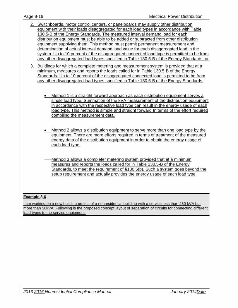
2. Switchboards, motor control centers, or panelboards may supply other distribution equipment with their loads disaggregated for each load types in accordance with Table 130.5-B of the Energy Standards. The measured interval demand load for each distribution equipment must be able to be added or subtracted from other distribution equipment supplying them. This method must permit permanent measurement and determination of actual interval demand load value for each disaggregated load in the system. Up to 10 percent of the disaggregated connected load type is permitted to be from any other disaggregated load types specified in Table 130.5-B of the Energy Standards; or
3. Buildings for which a complete metering and measurement system is provided that at a minimum, measures and reports the loads called for in Table 130.5-B of the Energy Standards. Up to 10 percent of the disaggregated connected load is permitted to be from any other disaggregated load types specified in Table 130.5-B of the Energy Standards.
Method 1 is a straight forward approach as each distribution equipment serves a single load type. Summation of the kVA measurement of the distribution equipment in accordance with the respective load type can result in the energy usage of each load type. This method is simple and straight forward In terms of the effort required compiling the measurement data.
Method 2 allows a distribution equipment to serve more than one load type by the equipment. There are more efforts required in terms of treatment of the measured energy data of the distribution equipment in order to obtain the energy usage of each load type.
Method 3 allows a completer metering system provided that at a minimum measures and reports the loads called for in Table 130.5-B of the Energy Standards, to meet the requirement of §130.5(b). Such a system goes beyond the setup requirement and actually provides the energy usage of each load type.
Example 8-6
I am working on a new building project of a nonresidential building with a service less than 250 kVA but more than 50kVA. Following is the proposed concept layout of separation of circuits for connecting different load types to the service equipment.

Electrical Power Distribution – Disaggregation Separation of Electrical Circuits for Electrical Energy Monitoring - §130.5(b) Page 8-17
2013 2016 Nonresidential Compliance Manual January 2014Date
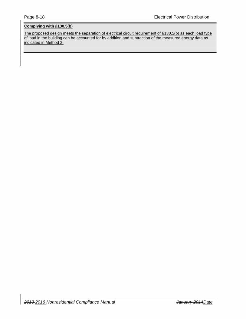
Complying with §130.5(b)
The proposed design meets the separation of electrical circuit requirement of §130.5(b) as there are separations of circuits for connecting different load types to the service equipment. There should be provisions including physical spaces for future setup of measurement devices for energy monitoring at each electrical installation location.
Example 8-7
Part of my proposed design is to use have a distribution panel serving HVAC loads and the panel also subfeeding a lighting subpanel. There is another panel feeding receptacle or plug load only.
These are all the load types for the proposed new building and the building service is rated at 250kVA.
All lighting loads in aggregate
All HVAC loads in aggregate
All plug loads in aggregate
All water system loads in aggregate
All EV charging station loads in aggregate
All plug loads in aggregate
All elevator loads in aggregate Each renewable system group
To HVAC loads only
To lighting loads only
Distribution Panel feeds
Lighting Panel
Subpanel
Subpanel
Receptacle
Panel
Subpanel
feeder
feeder
Page 8-18 Electrical Power Distribution
2013 2016 Nonresidential Compliance Manual January 2014Date
Complying with §130.5(b)
The proposed design meets the separation of electrical circuit requirement of §130.5(b) as each load type of load in the building can be accounted for by addition and subtraction of the measured energy data as indicated in Method 2.

Electrical Power Distribution – Disaggregation Separation of Electrical Circuits for Electrical Energy Monitoring - §130.5(b) Page 8-19
2013 2016 Nonresidential Compliance Manual January 2014Date
Example 8-8
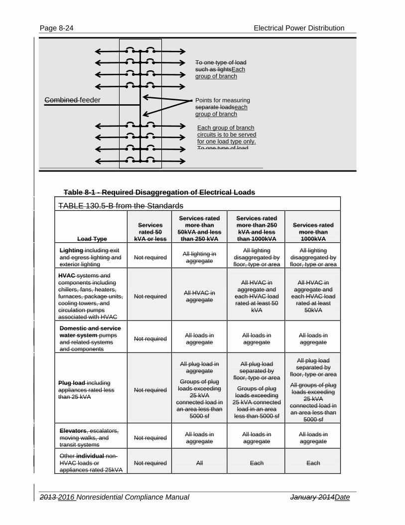
Can a panelboard with a split bus system feeding two groups of branch circuits be allowed to be used for meeting the separation of electrical circuit requirement?
Each group of circuits is to be served no more than one load type. Below is a figure for such a panelboard.
Complying with §130.5(b)
The proposed equipment above allows each load type to be separately measured for energy usage and therefore can be used to meet the requirements of §130.5(b).
Example 8-9
Can a panelboard with provisions allowing branch circuit energy monitoring be allowed to be used for meeting the separation of electrical circuit requirement? Each circuit is to be served with no more than one load type. Below is a figure for such a panelboard.
Complying with §130.5(b)
The proposed equipment above allows each load type to be separately measured for energy usage and therefore can be used to meet the requirements of §130.5(b).
Each group of branch circuits is to be served for one load type only.
Each group of branch circuits is to be served for one load type only.
Points for measuring each group of branch circuits
feeder
Each circuit feeds one type of load only.
Points for measuring separate loads
feeder
Page 8-20 Electrical Power Distribution
2013 2016 Nonresidential Compliance Manual January 2014Date
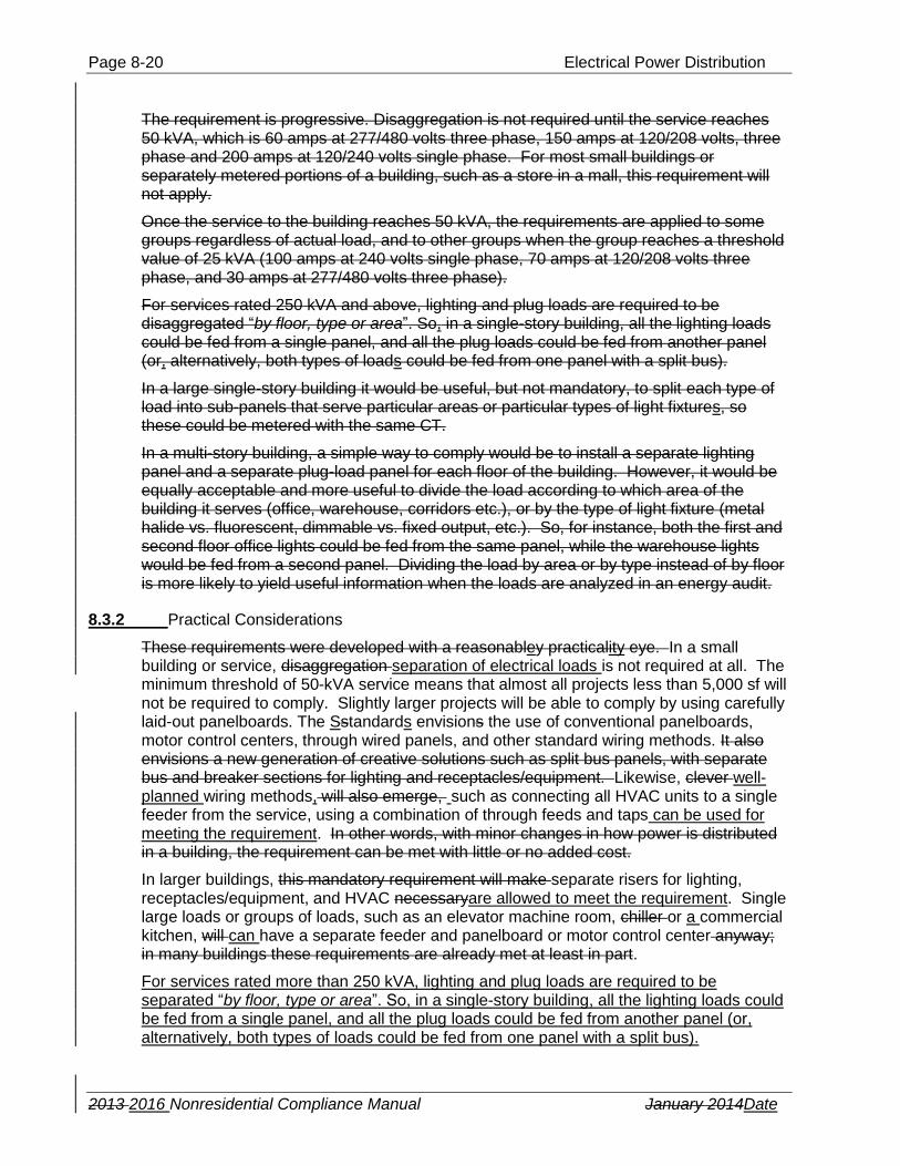
The requirement is progressive. Disaggregation is not required until the service reaches 50 kVA, which is 60 amps at 277/480 volts three phase, 150 amps at 120/208 volts, three phase and 200 amps at 120/240 volts single phase. For most small buildings or separately metered portions of a building, such as a store in a mall, this requirement will not apply.
Once the service to the building reaches 50 kVA, the requirements are applied to some groups regardless of actual load, and to other groups when the group reaches a threshold value of 25 kVA (100 amps at 240 volts single phase, 70 amps at 120/208 volts three phase, and 30 amps at 277/480 volts three phase).
For services rated 250 kVA and above, lighting and plug loads are required to be disaggregated “by floor, type or area”. So, in a single-story building, all the lighting loads could be fed from a single panel, and all the plug loads could be fed from another panel (or, alternatively, both types of loads could be fed from one panel with a split bus).
In a large single-story building it would be useful, but not mandatory, to split each type of load into sub-panels that serve particular areas or particular types of light fixtures, so these could be metered with the same CT.
In a multi-story building, a simple way to comply would be to install a separate lighting panel and a separate plug-load panel for each floor of the building. However, it would be equally acceptable and more useful to divide the load according to which area of the building it serves (office, warehouse, corridors etc.), or by the type of light fixture (metal halide vs. fluorescent, dimmable vs. fixed output, etc.). So, for instance, both the first and second floor office lights could be fed from the same panel, while the warehouse lights would be fed from a second panel. Dividing the load by area or by type instead of by floor is more likely to yield useful information when the loads are analyzed in an energy audit.
8.3.2 Practical Considerations
These requirements were developed with a reasonabley practicality eye. In a small building or service, disaggregation separation of electrical loads is not required at all. The minimum threshold of 50-kVA service means that almost all projects less than 5,000 sf will not be required to comply. Slightly larger projects will be able to comply by using carefully laid-out panelboards. The Sstandards envisions the use of conventional panelboards, motor control centers, through wired panels, and other standard wiring methods. It also envisions a new generation of creative solutions such as split bus panels, with separate bus and breaker sections for lighting and receptacles/equipment. Likewise, clever well-planned wiring methods, will also emerge, such as connecting all HVAC units to a single feeder from the service, using a combination of through feeds and taps can be used for meeting the requirement. In other words, with minor changes in how power is distributed in a building, the requirement can be met with little or no added cost.
In larger buildings, this mandatory requirement will make separate risers for lighting, receptacles/equipment, and HVAC necessaryare allowed to meet the requirement. Single large loads or groups of loads, such as an elevator machine room, chiller or a commercial kitchen, will can have a separate feeder and panelboard or motor control center anyway; in many buildings these requirements are already met at least in part.
For services rated more than 250 kVA, lighting and plug loads are required to be separated “by floor, type or area”. So, in a single-story building, all the lighting loads could be fed from a single panel, and all the plug loads could be fed from another panel (or, alternatively, both types of loads could be fed from one panel with a split bus).

Electrical Power Distribution – Disaggregation Separation of Electrical Circuits for Electrical Energy Monitoring - §130.5(b) Page 8-21
2013 2016 Nonresidential Compliance Manual January 2014Date
In a large single-story building, it would be useful but not mandatory , to split each type of load into sub-panels that serve particular areas or particular types of light fixtures.
In a multi-story building, a simple way to comply would be to install a separate lighting panel and a separate plug-load panel for each floor of the building. However, it would be equally acceptable and more useful to divide the load according to which area of the building it serves (office, warehouse, corridors etc.), or by the type of light fixture (metal halide vs. fluorescent, dimmable vs. fixed output, etc.). So, for instance, both the first and second floor office lights could be fed from the same panel, while the warehouse lights would be fed from a second panel. Dividing the load by area or by type instead of by floor is more likely to yield useful information when the loads are analyzed in an energy audit.
For buildings with a single large service greater than 50 kVA, such as retail malls, offices and apartment buildings that have submetered distribution to completely demised tenants, the requirements apply as follows:
1. Common areas of the building must be disaggregated 2. Individual submetered services must be disaggregated if the submetered service is
50 kVA or greater, with the exception of residential units, in which disaggregation is not required.
In remodeled or renovated buildings, the total electrical load is expected to be reduced as Title 24 lighting power requirements, HVAC requirements, insulation and glazing requirements, etc. will necessarily cause the original building to use less energy, and to a certain extent a building can be enlarged without increasing the service or existing feeders and panels. As long as the only changes to the electrical system involve changes to branch breakers and branch circuits, this mandatory requirement is not invoked.

Page 8-22 Electrical Power Distribution
2013 2016 Nonresidential Compliance Manual January 2014Date
Example 8-1
Single panel with service less than 50 kVA, which is less than 60A@ 277/480v 3ϕ, 135A @ 120/208v 3ϕ,
or 200A @ 120/240v 1ϕ
No requirements for disaggregated wiring
Example 8-2
BASIC REQUIREMENTS FOR DISAGGREGATED WIRING
Service panel with service less than 250 kVA, which is less than 300A@ 277/480v 3ϕ, 690A @ 120/208v
3ϕ, or 1000A @ 120/240v 1ϕ
This would be typical of a small school or office building (~25,000 to 50,000 sf), small retail or grocery store (~10,000 to 20,000 sf), etc.
Each feeder serves a breaker panel, load center, or load or load group with its own disconnect and subdistribution.
NOTES
Large loads smaller than 25 kVA can be connected to load centers or plug load groups
Load centers can be used to aggregate many small equipment loads such as commercial or industrial equipment, computer server rooms, commercial kitchens, retail refrigeration, etc.
A single multi-pole breaker can be used to feed all branch circuit loads of one type, such as all lighting loads, in smaller buildings.
All lighting loadss in aggregate
All HVAC loads in aggregate
All plug loads in aggregate
All water system loads in aggregate
All elevators and escalatorsEV charging station loads in aggregate
All plug loads in aggregateAll load centers
All elevator loads in aggregate Renewable system Each renewable system group All large loads 25 kVA or greater

Electrical Power Distribution – Disaggregation Separation of Electrical Circuits for Electrical Energy Monitoring - §130.5(b) Page 8-23
2013 2016 Nonresidential Compliance Manual January 2014Date
Example 8-3
Using a distribution panel to subfeed branch circuit panelboards. Can be used for lighting, HVAC, plug loads, or any other group of load types.
Example 8-4
Combined lighting panel with subfeed to other lighting panel(s).
A larger first lighting panel (e.g. 400 amps) could subfeed three 100-amp panels, or 6 60-amp panels, and serve local branch circuits, too.
Can be used for lighting, HVAC, plug loads, or any other group of load types.
Example 8-5
Using a split bus panel to feed two groups of branch circuits. Can be used for lighting, HVAC, plug loads, or any other group of load types. Limited to use in smaller projects where only one panel is needed for each load type.
To lighting panel
To lighting panel
To lighting panel
To lighting panel
To lighting panel
To lighting panel
To lighting panel
To lighting panel
To To lighting HVAC circuitsloads only
To lighting lighting loads circuitsonly
Lighting Distribution
Page 8-24 Electrical Power Distribution
2013 2016 Nonresidential Compliance Manual January 2014Date
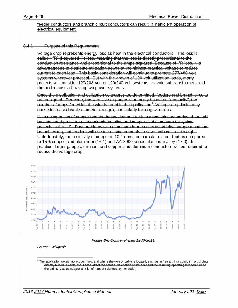
Table 8-1 - Required Disaggregation of Electrical Loads
TABLE 130.5-B from the Standards
Load Type
Services rated 50
kVA or less
Services rated more than
50kVA and less than 250 kVA
Services rated more than 250 kVA and less than 1000kVA
Services rated more than 1000kVA
Lighting including exit
and egress lighting and exterior lighting
Not required All lighting in
aggregate
All lighting disaggregated by floor, type or area
All lighting disaggregated by floor, type or area
HVAC systems and
components including chillers, fans, heaters, furnaces, package units, cooling towers, and circulation pumps associated with HVAC
Not required All HVAC in aggregate
All HVAC in aggregate and
each HVAC load rated at least 50
kVA
All HVAC in aggregate and
each HVAC load rated at least
50kVA
Domestic and service water system pumps
and related systems and components
Not required All loads in aggregate
All loads in aggregate
All loads in aggregate
Plug load including
appliances rated less than 25 kVA
Not required
All plug load in aggregate
Groups of plug loads exceeding
25 kVA connected load in an area less than
5000 sf
All plug load separated by
floor, type or area
Groups of plug loads exceeding
25 kVA connected load in an area
less than 5000 sf
All plug load separated by
floor, type or area
All groups of plug loads exceeding
25 kVA connected load in an area less than
5000 sf
Elevators, escalators,
moving walks, and transit systems
Not required All loads in aggregate
All loads in aggregate
All loads in aggregate
Other individual non-
HVAC loads or appliances rated 25kVA
Not required All Each Each
To one type of load such as lightsEach group of branch circuits is to be served
Each group of branch circuits is to be served for one load type only. To one type of load
Points for measuring separate loadseach group of branch circuits
Combined feeder

Electrical Power Distribution – Voltage Drop Requirements - §130.5(c) Page 8-25
2013 2016 Nonresidential Compliance Manual January 2014Date
or greater
Industrial and commercial load centers 25 kVA or
greater including theatrical lighting installations and commercial kitchens
Not required All Each Each
Renewable power source (net or total)
Each group Each group Each group Each group
Loads associated with renewable power source
Not required All loads in aggregate
All loads in aggregate
All loads in aggregate
Charging stations for electric vehicles
All loads in aggregate
All loads in aggregate
All loads in aggregate
All loads in aggregate
8.4 Voltage Drop Requirements - §130.5(c)
This is a new Section. It makes the recommended voltage drop limits from the California Electrical Code (Title 24 Part 3) mandatory. Specifically,The voltage drop requirement, which has been clarified and revised in the 2016 update of the Standards, is as follows.
Voltage drop of feeder + Voltage drop of branch circuit ≤ 5% The voltage drop in feeders is limited to 2% of design load; and.
The maximum combined, voltage drop on both installed feeder conductors and branch circuit conductors to the farthest connected load or outlet shall not exceed 5 percent. This is the steady-state voltage drop under normal load condition.
Note the following information: The voltage drop in branch circuits is limited to 3% of design load.
Emergency power circuits are exempt Voltage drop requirements of California Electrical Code (CEC) sections are exempted from the requirement of §130.5(c).
1. - Article 647, Sensitive Electronic Equipment, Section 647.4 Wiring Methods 2. - Article 695, Fire Pump, Section 695.6, Power Wiring 3. - Article 695, Fire Pump, Section 695.7, Voltage Drop
The Informational Note about voltage drop in Article 210, Branch Circuits, of the CEC is not part of the requirements of California Electrical Code. The same goes for the Informational Note about voltage drop in Article 215, Feeders, of the CEC.
Voltage drop represents energy lost as heat in the electrical conductors. The loss is called “I2R” (I-squared-R) loss, meaning that the loss is directly proportional to both the conductor resistance and l to the current squared. Because of I2R loss, it is advantageous to distribute utilization power at the highest practical voltage to reduce the amount of current into each load.
Voltage drop losses are cumulative, so voltage drop in feeders and voltage drop in branch circuits add up to the load at the end of the branch circuit. Excessive voltage drop in the
Page 8-26 Electrical Power Distribution
2013 2016 Nonresidential Compliance Manual January 2014Date
feeder conductors and branch circuit conductors can result in inefficient operation of electrical equipment.
8.4.1 Purpose of this Requirement
Voltage drop represents energy loss as heat in the electrical conductors. The loss is called “I2R” (I-squared-R) loss, meaning that the loss is directly proportional to the conduction resistance and proportional to the amps squared. Because of I2R loss, it is advantageous to distribute utilization power at the highest practical voltage to reduce current to each load. This basic consideration will continue to promote 277/480-volt systems wherever practical. But with the growth of 120-volt utilization loads, many projects will consider 120/208-volt or 120/240-volt systems to avoid subtransformers and the added costs of having two power systems.
Once the distribution and utilization voltage(s) are determined, feeders and branch circuits are designed. Per code, the wire size or gauge is primarily based on “ampacity”, the number of amps for which the wire is rated in the application2. Voltage drop limits may cause increased cable diameter (gauge), particularly for long wire runs.
With rising prices of copper and the heavy demand for it in developing countries, there will be continued pressure to use aluminum alloy and copper clad aluminum for typical projects in the US. Past problems with aluminum branch circuits will discourage aluminum branch wiring, but feeders will use increasing amounts to save both cost and weight. Unfortunately, the resistivity of copper is 10.4 ohms per circular mil per foot as compared to 15% copper-clad aluminum (16.1) and AA-8000 series aluminum alloy (17.0). In practice, larger gauge aluminum and copper clad aluminum conductors will be required to reduce the voltage drop.
Figure 8-6 Copper Prices 1986-2011
Source: Wikipedia
2 The application takes into account how and where the wire or cable is located, such as in free air, in a conduit in a building,
directly buried in earth, etc. These affect the cable’s dissipation of the heat and the resulting operating temperature of the cable. Cables subject to a lot of heat are derated by the code.

Electrical Power Distribution – Voltage Drop Requirements - §130.5(c) Page 8-27
2013 2016 Nonresidential Compliance Manual January 2014Date
8.4.2 Applying Voltage Drop Calculations
Voltage drop losses are cumulative, so that 2% loss in feeders and 3% loss in branch circuits add up to 5% loss relative to the load at the end of the branch circuit. Because electrical loads are not constant, the calculation is based on design load. For feeders, this is the calculated maximum demand load on the circuit per the California Electrical Code but does not include any of the additional ampacity required by the California Electric Code. For branch circuits, the design load is either (a) the branch circuit rating for receptacle loads (usually 16 amps), or (b) the 100% load of a specific load such as motor or fixed equipment.
The calculation is for the total length of the feeder, and for the maximum length of branch circuit to the load. For branch circuits, this calculation can be excessively complicated in many cases. For this reason, any of the following methods can be used to calculate branch circuit voltage drop:
a) A load-by-load, detailed calculation of the voltage drop. This is required for circuits with specific loads such as motors or fixed equipment.
b) For circuits with many loads such as receptacles, determine the approximate centroid of the load. The centroid is defined as the weighted center of all possible load locations. For a receptacle or lighting circuit, it is the physical center of the room or all rooms served by the circuit. Determine the voltage drop at that point for the actual load or 75% of the maximum allowable circuit amps, whichever is greater.
c) For circuits as b) but with a common neutral and multiple phase conductors carried as far as a first major junction box, the voltage drop calculated above may be reduced 25% to account for the cancelation of neutral current before the neutral is tapped and single phase circuits begin.
8.4.3 Calculations
While voltage drop calculations can be performed by hand, they are also the output of most modern power design computer programs. In addition there are handy calculators on the Internet3 and procedures for determining voltage drop are printed in electrician’s handbooks4.
Calculations are relatively straightforward. Multiply the allowed voltage-drop percentage (2% for feeders, 3% for branch circuits) by the nominal system voltage. This is the allowed drop in the feeder or branch circuit. Note to be careful whether calculating voltage drop in a single-phase or three-phase system, as illustrated in the following example.
Example 8-6
In a 120/208 volt system, the allowed voltage drop for a single phase 120 volt branch circuit load is (120 *.03) = 3.6 volts. For the feeder in the same 120/208 volt three phase system, the allowed voltage drop is (120*.02) = 2.4 volts, for a cumulative loss of 6 volts (5%).
Next, calculate the actual voltage drop in the circuit. Multiply the resistance times the length of wire in the circuit. Remember, the length of wire is TWICE the distance, as current must flow to the load and back. For three phase circuits, the allowed voltage drop is based on line-to-line volts, not line-to-neutral volts.
3 www.electrical-installation.org
4 Ugly’s Electrical References, George Hart and Sammie Hart, Jones and Bartlett, Publishers

Page 8-28 Electrical Power Distribution
2013 2016 Nonresidential Compliance Manual January 2014Date
Example 8-7
In a 120/208 volt system, a single-phase branch circuit runs 100 feet to the centroid of a number of receptacles. Assuming 12 amps (75% of the maximum allowed load) and cooper wire, the voltage drop in the branch circuit will be
With #12 wire @ .00187 ohms/ft, Edrop = IR = 12*100*2*.00187 = 4.48 volts
With #10 wire @ .00118 ohms/ft, Edrop = IR = 12*100*2*.00118 = 2.81 volts
With #8 wire @ .000739 ohms/ft, Edrop = IR = 12*100*2*.000739 = 1.76 volts
In this case, the branch circuit should be #10 to the first load or junction box. The remainder of the circuit could probably be wired with #12 gauge provided there are no long runs or single large loads.
Example 8-8
A service panel feeds a 120/208 volt three phase panelboard 150 feet away. The design load is 80 amps, three-phase. The panel mains and feeder breaker are rated 100 amps. By code the feeder must be at least #3 AWG copper, but the more common size #2 AWG is used. Does it comply?
For #2 AWG, E = IR = .000513 ohms/ft *150 ft *2* 80 amps =12.3 volts. But the allowed drop is 208 * .02 = 2.4 volts. The answer is no, there will be too much loss in the feeder.
The proper feeder will be at least 400 MCM copper to achieve 2.4 volts or less in voltage drop.
8.4.4 Suggested Calculation Approach
Voltage drop calculations are of two principal types:
Voltage drop in feeders, which are conductors carrying current from one switchboard or panelboard to another; and
Voltage drop in branch circuits, which are conductors carrying current from a switchboard or panelboard to one or more connected loads.
As a general rule, “switchboards” include service entrance5 or disconnecting gear with or without distribution sections, power distribution gear of switchboard construction6 and employing feeder and/or branch circuit distribution breakers or fusible disconnects, motor control centers with motor starters and/or distribution breakers or fusible disconnects, and similar equipment. “Panelboards” include service entrance or disconnecting gear with or without distribution sections, power distribution gear of panelboard construction7 and employing feeder and/or branch circuit distribution breakers, and similar equipment.
A. Determining Load Current
For the purposes of voltage drop calculations, loads must be included as volt-amperes (VA), not watts. Because of the increased use of electronic equipment, unity power factor
5 The necessary equipment, usually consisting of a circuit breaker(s) or switch(es) and fuse(s) and their accessories,
connected to the load end of service conductors to a building or other structure, or an otherwise designated area, and intended to constitute the main control and cutoff of the supply. (California Electrical Code, Section 110)
6 A large single panel, frame, or assembly of panels on which are mounted on the face, back, or both, switches, overcurrent and other protective devices, buses, and usually instruments. Switchboards are generally accessible from the rear as well as from the front and are not intended to be installed in cabinets. (Ibid)
7A single panel or group of panel units designed for assembly in the form of a single panel, including buses and automatic overcurrent devices, and equipped with or without switches for the control of light, heat, or power circuits; designed to be placed in a cabinet or cutout box placed in or against a wall, partition, or other support; and accessible only from the front. (Ibid)

Electrical Power Distribution – Voltage Drop Requirements - §130.5(c) Page 8-29
2013 2016 Nonresidential Compliance Manual January 2014Date
should not be assumed. For the purposes of this calculation, if power factor is known, the following power factors can be used to determine VA and thereby, circuit amps.
For instance, the minimum allowed power factor (pf) for an Energy Star LED lamp is 70% (0.7). Assume a lamp rated at 12 watts at 120 volts. The volt-amps will be
VA = Watts/pf
In this case, the VA will be (12/.7) = 17.14 VA and the current at 120 volts will be about .143 amps. This means that a maximum of (16/.143) = 111.8 lamps can be placed on a standard 20 amp circuit. If watts had been used instead of VA, the designer or electrician would have assumed that 160 lamps could be used on a circuit, which would have then drawn nearly 23 amps and tripped the breaker.
In an ideal world, the watts and VA of a load would be equal (pf = 1.0 or 100%). But many LED lighting and electronic branch circuit loads have poor power factor (80% or less). Poor power factor means that the load draws current but does not use all of the power, in essence storing the energy and returning it to the circuit unused. This causes inefficiency as the unused energy still causes power losses in transformers, conductors and other system components. Moreover, many utility tariffs charge customers extra for poor power factor.

Page 8-30 Electrical Power Distribution
2013 2016 Nonresidential Compliance Manual January 2014Date
Example 8-9
Voltage drop for a proposed design scenario case #1:
Voltage drop for a proposed design scenario case #2:
Voltage drop for a proposed design scenario case #3:
Complying with §130.5(c)
All the above proposed design scenarios, meets the voltage drop requirement of §130.5(c) as the combined voltage drop on both the feeder conductor and branch circuit conductors do not exceed 5 percent.
Table 8-2 Typical Power Factors for Voltage Drop Calculations
Load Type Default Power
Factor at 120 volts Default Power
Factor at 277 volts Note
Fluorescent lighting
0.95 0.95 ------
Compact fluorescent lighting
0.9 (hardwired)
0.5 (GU-24)
0.9 (hardwired)
0.3 (GU-24)
NPF magnetic ballasts use GU-24 values
Determine the voltage drop on this feeder, which is 110 feet longFeeder with voltage drop of 2%
Light
Determine the voltage drop on this feeder, which is 110 feet longFeeder with voltage drop of 1%
Light
Feeder with voltage drop of 32%
Light
Determine the voltage drop on this feeder, which is 110 feet longBranch circuit with voltage drop of 3%
Load
Determine the voltage drop on this feeder, which is 110 feet longBranch circuit with voltage drop of 4%
Load
Branch circuit with voltage drop of 23%
Load

Electrical Power Distribution – Voltage Drop Requirements - §130.5(c) Page 8-31
2013 2016 Nonresidential Compliance Manual January 2014Date
LED lighting 0.7 0.5
May be higher if specifications call for
high power factor drivers
Incandescent lighting
1.0 1.0 ------
HID lighting 0.9 0.9 May be lower if NPF ballasts are specified
HVAC packages 0.85 0.9 ------
Other motors <5 HP
0.8 0.8 ------
Other motors >5 HP
0.85 0.85 ------
Kitchen equipment 0.9 N/A ------
Receptacles 0.6 N/A
For dedicated receptacles, may be
rated according to the load
Electric heating including hot water
1.0 1.0 ------
Other 0.85 0.85 ------
B. Resistance versus Impedance
The resistance of wire (R) is relatively constant and predictable based on material, stranded versus solid cable, and length. There are small variations due to temperature, but for the purposes of voltage drop calculations in building wiring, the resistance at 25°C is generally suitable.
On the other hand, the impedance of wire (Z) depends on many factors, including type of conduit (if any), whether the wires are twisted, and type of insulation. Moreover, in normal operating calculations (not short circuit calculations), the inductive reactance (XL) plays a small role in circuit impedance, and at 60 Hz, the capacitive reactance (XC) plays little role in circuit behavior. Moreover, in DC circuits neither XL nor XC matter except under transient and short circuit conditions. Because R is the dominant cause of voltage drop, use of wiring resistance only is acceptable for the purposes of these calculations.
C. Feeder Calculations
The approximate length of the feeder can be determined by examining the plans and estimating the route that the installing contractor will use. This estimate should include lateral and vertical conduit lengths, with routing at right angles to the building structure8. Diagonal routing may be used for calculations only if indicated on the plans. Note that this estimate should take into account any known conditions shown on the plans, and accuracy of 10% or better is considered acceptable. 8 These requirements call for assuming right angle (orthogonal) conduit routing as in general, such practice is considered
proper workmanship. However, if a diagonal route is specified in the plans, it may be used and will typically resort in a shorter circuit. Engineers and electrical designers are encouraged to seek such specifications as this will result in lower energy loss and/or less construction materials, especially conductors.

Page 8-32 Electrical Power Distribution
2013 2016 Nonresidential Compliance Manual January 2014Date
The calculation should assume the design load per connected panelboard or switchboard load calculations. This means that the schedule for every panel should be shown on the plans, with circuit VA loads determined according to the California Electrical Code. The voltage drop should be based on the load and is not required to include derating factors. However, if spare feeder or branch circuit overcurrent protection devices or future spaces are provided in the connected panelboard or switchboard, then they are typically assumed to be loaded to 50% of rating. However, in any event the load of the connected panelboard or switchboard must not exceed its full rated load. .
If detailed load schedules are not available, or simply for ease of calculations, the voltage drop for the feeder may assume the connected panelboard or switchboard to being operated at 80% of rated ampacity. For example, for the feeder to a 400 amp panelboard, it is acceptable to assume (400*.8) = 320 amps.
Example 8-9
Feeder calculations
Basic Calculation
A service switchboard feeds a 277/480 volt 400 amp distribution panelboard (power panel) with the following schedule of devices and loads:
Section 1 - 200-amp three phase breaker – feeds rooftop HVAC unit rated 125 full load amps (FLA) with 500 locked rotor amps (LRA), minimum breaker size 175 amps
Section 2 – 100A three-phase breaker – feeds downstream 100A lighting panelboard with 65-amp three-phase connected load and no spare breakers.
Section 3 – (3) 20-amp single-phase breakers feeding local lighting loads of 12 amps, 8 amps and 10 amps, respectively
Section 4 – (1) 60-amp three-phase breaker feeding an electric water heater rated 18 kW and 43 amps per phase
This example includes a number of common load types and considerations.
Section 1: for the feeder voltage drop calculation, full load amps (FLA) are to be used. The load on the feeder is 125-amps, three-phase.
Section 2: for the feeder voltage drop calculation, the lighting load of 65-amps, three-phase is used at 100%.
Section 3: for the feeder voltage drop calculation, the largest single-phase current is assumed for all three phases, or 12 amps at 100%.
Service panel – 1200A 277/480 V 3ø 4 W
Power panel – 400A 277/480 V 3ø 4 W Determine the
voltage drop on this feeder, which is 110 feet long
HVAC-1
Light
EWH-1

Electrical Power Distribution – Voltage Drop Requirements - §130.5(c) Page 8-33
2013 2016 Nonresidential Compliance Manual January 2014Date
Section 4: for the feeder voltage drop calculation, the three-phase load of the water heater is (18,000 watts)*1.0 = 18 KVA, or (18KVA/.832) = 21.6 amps.
The total maximum connected load amps is (125+65+12+22) = 224 amps.
The engineer specifies (2) 4/0 aluminum 90°C wire (rated 205 amps) aluminum per phase. The resistance of 4/0 stranded aluminum wire is .08360 ohms per 1000 feet at 25° C, so the resistance of two conductors per phase is (.08360/2) = .04180 ohms per 1000 feet. The maximum permissible voltage drop (line to line) is 480 volts * .02 = 9.6 volts.
The total circuit length (line-line) is 110 feet *2 = 220 ft. The circuit voltage drop is
E = IR = Amps x Resistance per 1000’ x length(ft)/1000 =
224 * .04180 * .220 = 2.1 volts (passes the test)
Spares and Spaces Calculation
Now assume that the power panel above has the following spares and spaces:
Section 5 – 60-amp three-phase spare
Section 6 – 100-amp three-phase space
These are typiaclly counted at 50% load (or greater). This means that the new total load for the panel is (100+60)*.5 = 80 amps. The new total load is 224 amps (as determined above) plus 80 amps for a total of 304 amps.
Repeating the calculation above, the voltage drop in the specified (2) #4/0 aluminum conductors per phase is
E = IR = 304 * .04180*.220 = 2.8 volts (passes the test)
Ampacity Rating
For simplicity or when loads are not known, it is permissible to use 80% of the panel’s rated current. The power panel is rated at 400 amps three-phase, so the load to be used is 400*.8 = 320 amps. The voltage drop is
320* .04180*.220 = 2.9 volts (passes the test)
In order to expedite design, as an alternative to performing detailed calculations, Table 130.5-B allows the selection of acceptable combinations of feeder conductors and distance meeting these voltage-drop requirements.
D. Branch Circuit Calculations
Branch circuits provide power from switchboards, panelboards or other distribution centers to individual loads or groups of loads. An example of an individual load is a rooftop package HVAC unit, which although technically is a group of loads including a compressor, fan, control circuits, etc., it is all in one place and the manufacturer provides the total load amps for the package unit. An example of a group of loads is a lighting

Page 8-34 Electrical Power Distribution
2013 2016 Nonresidential Compliance Manual January 2014Date
branch circuit, to which a large number of individual loads might be connected over a large area.
As a general rule for individual loads, the location of the load is known. First determine the length of the branch circuit, taking into account both the lateral and vertical distance from power source to load. Conduit routing is usually at right angles to the building structure unless specifically shown on the plans. Next, determine the branch circuit voltage drop assuming 100% of rated load, calculated per the California Electrical Code. Derating factors used to determine current amps and conductor size do not need to be included.
As a general rule for branch circuits with multiple loads, in plan identify all loads on the circuit. Determine the centroid of the loads on the circuit, which is defined as the weighted central location of the group of loads. It isusual to determine the approximate location of the centroid of the loads simply by “judging by eye”.. The length of the branch circuit is defined as the distance from this point to the power source. Assume conduit routing at right angles to the building structure unless specifically shown on the plans9. Next, determine the branch circuit voltage drop; this can be based on the following load factors, calculated per the California Electrical Code. Derating factors used to determine current amps and conductor size do not need to be included. Note that since the intent of this calculation is to determine the voltage drop that is primarily contained in the home-run conductors with an approximation for tap conductors, this method can be used for any wiring method.
Table 8-3 Branch Circuit Load Factor
Load type
Percentage of Code connected load to be
used Notes and Special exceptions
Lighting 100%
Receptacles 75% 100% of all equipment loads using cord and
plug connection
Combined lighting and
receptacle
100% of lights and 75% of receptacles
------
Tapped circuits
75% of receptacles
100% of all other loads
For circuits tapped downstream to supply mixed loads
Note: as a convenience, the calculation may assume the allowed branch circuit capacity. In general, this is 80% of the rating of the overcurrent protection device, e.g. 16 amps for a 20-amp circuit. This is especially recommended for lighting and receptacle branch circuits that might have additional loads connected later.
9 These requirements call for assuming right angle (orthogonal) conduit routing as in general, such practice is considered
proper workmanship. However, if a diagonal route is specified in the plans, it may be used and will typically resort in a shorter circuit. Engineers and electrical designers are encouraged to seek such specifications as this will result in lower energy loss and/or less construction materials, especially conductors.

Electrical Power Distribution – Voltage Drop Requirements - §130.5(c) Page 8-35
2013 2016 Nonresidential Compliance Manual January 2014Date
Example 8-10
Single Load Example
A package HVAC unit running on 208 volts, three-phase has a full load amp (FLA) rating of 10.5 amps and locked rotor amps (LRA) of 45 amps. The engineer specified #12 wires and a 20 amp 3-pole breaker. The physical distance is 200 feet. What is the voltage drop and does it meet section 130.5?
On a 208 volt line-to-line circuit, the allowed branch circuit voltage drop is 3%, or (208*.03) = 6.24 volts.
The resistance of solid copper #12 wire is 1.62 ohms/1000 ft at 25° C. The voltage drop in this circuit is:
E = IR = 10.5*1.62 *(400/1000) = 6.84 volts (fails)
This circuit will require #10 wires.
Example 8-11
Centroid Example
90 LED troffers are located in an office space. Each troffer is an LED luminaire rated at 277 volts, 42 watts
and .16 amps, for a total of 14.4 amps for all 90 luminaires. 10 The centroid is at the weighted center of all the luminaires, meaning the “center of mass”. An approximate location is likely to be sufficient for compliance purposes. In this example, the centroid is about 150 feet from the panel. What is the voltage drop and does it meet section 130.5?
On a 277 volt line to neutral circuit, the allowed branch circuit voltage drop is 3%, or (277*.03) = 8.31 volts.
The resistance of solid copper #12 wire is 1.62 ohms/1000 ft at 25° C. The voltage drop in this circuit is:
E = IR = 14.4*1.62 *(300/1000) = 7.00 volts (passes)
Note that the voltage drop is (7/277) = 2.5%. The engineer might be advised to use #10 home run conductors and tap down to #12 for the remainder of the branch circuit.
Example 8-12
Branch Circuit Rating Example
It is permissible to use 80% of the branch circuit overcurrent protection device as the circuit current. This method is strongly recommended for branch circuits to which additional loads might be added in the future.
For #12 wires, the overcurrent protection device is 20-amps, so the current to be used for the calculation is 20 amps * 0.8 = 16 amps. If the conduit length is 225 feet, what is the voltage drop and does it meet section 130.5?
On a 277 volt line to neutral circuit, the allowed branch circuit voltage drop is 3%, or (277*.03) = 8.31 volts.
The resistance of solid copper #12 wire is 1.62 ohms/1000 ft at 25° C. The voltage drop in this circuit is:
E = IR = 16*1.62 *(450/1000) = 11.64 volts (fails)
For #10 stranded conductors,
E = IR = 16*1.04 *(450/1000) = 7.84 volts (passes)
The engineer should choose #10 home run conductors and may consider tapping down to #12 for the remainder of the branch circuit.
Table 8-4 Summary of Voltage Drop Limits
Circuit Volts (V) 2% Voltage
Drop (V) 3% Voltage
Drop (V) Total Loss (V)
10
Note that the power factor of this LED luminaire is 95% - this is common among better quality LED luminaires but not all LED luminaires. If the power factor and amp rating of the LED luminaire was not given, it would be necessary to use the default power factor of 0.5, which would limit the number of luminaires on the branch circuit to about 52.

Page 8-36 Electrical Power Distribution
2013 2016 Nonresidential Compliance Manual January 2014Date
120 2.4 3.6 6.0
208 4.2 6.2 10.4
240 4.8 7.2 12.0
277 5.5 8.3 13.9
480 9.6 14.4 24.0
Table 8-5 Voltage Drop for Common Copper Wire Gauges and Current Loads
Wire Circuit Amps
Maximum Feeder Length Maximum Branch Circuit Length
120 208 240 277 480 120 208 240 277 480
14* 12 39 67 78 90 156 58 101 117 135 233
12* 16 46 80 93 107 185 69 120 139 160 278
10 24 48 83 96 111 192 72 125 144 166 288
8 32 57 99 115 132 229 86 149 172 199 344
6 40 73 127 146 169 293 110 190 220 253 439
4 52 89 154 178 206 356 134 232 267 309 535
2 72 103 178 206 237 412 154 267 309 356 617
0 96 123 212 245 283 490 184 319 368 424 735
00 108 137 238 274 317 549 206 357 412 475 823
0000 144 163 283 327 377 654 245 425 490 566 980
250 (kcmil)
164 170 294 340 392 679 255 441 509 588 1019
300 184 181 314 362 418 725 272 471 543 627 1087
350 200 195 338 390 450 779 292 506 584 675 1169
500 248 224 388 448 517 896 336 582 672 776 1344

Electrical Power Distribution – Circuit Controls for 120-Volt Receptacles and Controlled Receptacles - §130.5(d) Page 8-37
2013 2016 Nonresidential Compliance Manual January 2014Date
Table 8-6 Voltage Drop for Common Aluminum Wire Gauges and Current Loads
Wire Circuit Amps
Maximum Feeder Length Maximum Branch Circuit Length
120 208 240 277 480 120 208 240 277 480
14* 12 24 41 47 55 95 36 62 71 82 142
12* 16 28 49 56 65 113 42 73 85 98 169
10 24 29 51 59 68 118 44 76 88 102 176
8 32 35 61 70 81 140 53 91 105 121 210
6 40 45 77 89 103 178 67 116 134 154 267
4 52 54 94 109 126 218 82 142 163 188 327
2 72 62 108 125 144 250 94 162 187 216 375
0 96 74 129 149 172 298 112 193 223 258 446
00 108 84 145 167 193 334 125 217 251 289 501
0000 144 99 172 198 229 397 149 258 298 344 595
250 (kcmil)
164 103 179 207 239 413 155 269 310 358 620
300 184 111 192 221 255 442 166 287 332 383 663
350 200 119 206 238 274 475 178 309 356 411 713
500 248 137 237 273 316 547 205 355 410 473 820
8.5 Circuit Controls for 120-Volt Receptacles and Controlled Receptacles - §130.5(d)
This new section addresses receptacles in offices. Office plug loads are now the largest power density loads in most office buildings. The Standards now requires both controlled and uncontrolled 120-volt receptacles in each private office, open office areasspaces, reception lobbiesy, conference rooms, kitchenette areas in office spaces, and copy rooms, hotel guest rooms and motel guest rooms.
In the 2016 update to the Standards, the requirement of circuit controls for 120-Volt receptacles and controlled receptacles arehave been clarified.
The requirement for controlled receptacles and controlled and uncontrolled circuitsreceptacles in all of these spaces allows plug loads to be turned off for energy savings, of the Energy Standards and perhaps, for demand response. These particular space types were singled out because they commonly employ portable lighting and other loads that can be automatically controlled to save energy.
The controlled outlets must be clearly different from uncontrolled outlets. The two principal ways to comply include:
1. For each uncontrolled outlet, provide a controlled outlet within 6 feet; or, 2. Use split wired duplex receptacles, with one uncontrolled and one controlled.
For open office areas, separate controlled and uncontrolled circuits must be provided to the workstations. If workstations are not installed at the time of occupancy, then when

Page 8-38 Electrical Power Distribution
2013 2016 Nonresidential Compliance Manual January 2014Date
installed, they must be equipped with non-residential power strips having motion controls built into the workstation, or alternatively, use the controlled and uncontrolled circuits already built in to the building system.
The controlled outlets must be automatically switched off in the same manner as required for general lighting, as described in Section 130.1(c.)when the space is not occupied. The most common means will be a local motion sensor that can be connected to control both general lighting and outlets and using the occupancy (not vacancy) control method. Another common method will be to employ time of day controls with manual override switches.
Note that plug strips with motion sensors CANNOT be used to meet this requirement. The intent is to have built-in, hardwired power controls. Wireless motion sensors can be used, but the actual power switch must be hardwired.
The requirement for controlled receptacles in all of these spaces allows plug loads to be turned off for energy savings, and perhaps, for demand response. These particular space types were singled out because they commonly employ portable lighting and other loads that can be automatically controlled to save energy.
There are important exceptions to not requiring a controlled outlet. They include: including:
1. Receptacles for refrigerators and water dispensers in kitchen areas.
2. Clock outletsReceptacles for clocks (mounted 6’ or more above the floor).
3. Outlets Receptacles for network copiers, fax machines, A/V and printers anddata equipment other than IT equipment (with the exception of personal computers)personal computers in copy rooms.
Outlets for refrigerators and water dispensary devices in kitchenettes.
4. OutletsReceptacles c onnected to an uninterruptible power supply (UPS) that are intended to be in continuous use, 24 hours per day/365 days per year.
8.5.1 Practical Application Considerations
In general, the most cost effective approach may beThe following are potential examples of cost-effective approaches:
A. Private Offices, Conference Rooms, and other Spaces with Periodic Occupancy
A common motion sensor can control general lighting and receptacles. If needed because ofDue to different voltages, an auxiliary relay can be connected to the sensor if needed. Likewise, with an auxiliary relay, the lighting system could be operated in the vacancy mode, and the controlled receptacles can be operated in the occupancy mode, thus permitting lights to be off while receptacles are on.
B. Lobbies, Break Rooms, and other Spaces with Frequent Occupancy During Business Hours
Time of day controls, with either a motion sensor or switch override, can switch the controlled receptacles. Programmable relay panels or controllable breakers can be used, or, for simpler less complex projects, a combination of motion sensors and programmable time switches can accomplish the same task. Note that if motion sensing is used, controls need to be room-by-room or space-by-space, but if time of day controls with manual override are used, whole circuits can be controlled together.
C. Open Office Areas

Electrical Power Distribution – Circuit Controls for 120-Volt Receptacles and Controlled Receptacles - §130.5(d) Page 8-39
2013 2016 Nonresidential Compliance Manual January 2014Date
Receptacles in open office areas can be controlled either by the building’s automatic shut-off system, or by controls integrated into the furniture systems. If the building provides controls, the most reliable system will most likely employ relays or controllable breakers, with manual override switches for zones within an open office space. A system using motion sensors might also be considered if sensors can be added as needed to address partitioning of the workstations (thus ensuring proper operation). Systems contained within workstation systems are an acceptable alternative provided that they are hardwired as part of the workstation wiring system.
D. Networked Control Systems and Building Automation Systems
Most advanced lighting and energy control systems can be easily designed to accommodate outlet receptacle controls.
Certain office appliances, e.g. computers and fax machines, need to be powered continuously during office hour all the time to provide uninterrupted services. These would be connected to the uncontrolled receptacles. Other appliances, e.g. task lamps, personal fans and heaters, and monitors, do not need to be powered without the presence of occupants. They are considered as controllable plug loads and would be plugged into the controlled receptacles for automatic shutoff controls. A hardwired control system provides the capability and convenience for automatic plug controls. Ultimately, it depends on building occupants to determine the appliances to be controlled.
In open office areas, it is better advisable to implement occupancy sensor control at each workstation (cubicle) to maximize the opportunities of shutoff controls. System furniture (cubicle) is usually
equippedusually equipped with more than one internal electrical circuit and some of these circuits can be dedicated for controllable plug loads.
Electric circuit connectors for system furniture are modularized and, therefore, split between controlled and uncontrolled circuits has to be made at a junction box. If external occupancy sensor switches are used, they all need to be wired to the corresponding junction box. and Tthe overall system wiring is complicated. In addition, oOff-the-shelf occupancy sensors are designed to be mounted on walls, not onto system furniture.
For the above reasons, office furniture with embedded occupancy sensor controls are the ideal choice for occupancy sensor controls in open office areas. Demand Response
Section 130.5 requires that, in any building or sign having mandatory provisions for demand response (DR), controls and equipment for DR shall be capable of receiving and automatically responding to at least one standards-based DR messaging protocol.
This requirement builds on the requirements of the following sections:
Section 130.1(e), which requires the lighting in buildings over 10,000 square feet to have automatic demand responsive control.
Section 130.3(a)3, which requires electronic message centers over 15 kW to have automatic demand responsive control.
Section 1401.0(b)2I, which requires lighting alteration projects to include automatic demand response in the altered space under certain circumstances, such as when wiring is added or modified, or when the lighting load in the space is increased.

Page 8-40 Electrical Power Distribution
2013 2016 Nonresidential Compliance Manual January 2014Date
8.5.2 Demand Rresponse - §130.5(e) Application Notes
Demand Response (DR) requirements of §130.5(e) requires that, in any building or sign having mandatory provisions for demand response, controls and equipment for DR shall be capable of receiving and automatically responding to at least one standards-based DR messaging protocol.
Demand Responsive Control is defined in §100.1 of the Energy Standards as “a kind of control that is capable of receiving and automatically responding to a demand response signal”.
Demand Response Signal is defined in §100.1 as “a signal sent by the local utility, Independent System Operator (ISO), or designated curtailment service provider or aggregator, to a customer, indicating a price or a request to modify electricity consumption, for a limited time period.”
§130.5(e) is related to the requirements of the following sections:
§130.1(e), which requires the lighting in buildings over 10,000 square feet, excluding spaces with a lighting power density of 0.5 W/ft2 or less, to be capable of automatically reducing lighting power in response to a Demand Responsive Signal; so that the total lighting power of non-excluded spaces can be lowered by a minimum of 15 percent below the total installed lighting power when a Demand Response Signal is received.
§130.3(a)3, which requires electronic message centers over 15 kW to have a control installed that is capable of reducing the lighting power by a minimum of 30 percent when receiving a Demand Response Signal .
§141.0(b)2I, which requires lighting alteration projects to include automatic demand response in the altered space under certain circumstances, such as for alterations larger than 10,000 ft2 in a single building. Note that this requirement only makes the building DR ready. It does not require buildings to actually respond to a demand signal. The decision to employ demand response is up to the building owner or manager, the utility company, and/or a governing authority.
Note: the above requirements do NOT mean that a building has to respond to real time price signals; the requirement is to ensure that the building is DR readyDemand response signal is defined in Section 100.1 of the Standards as “a signal sent from the local power utility, independent system operator (ISO), or designated curtailment service provider, to a customer, indicating a price or a request to modify electricity consumption for a limited time period”.
The requirements of Sections 130.1(e) and 130.5(e) . The decision to employ demand response is up to the building owner or manager, the utility company, and/or a governing authority. A building that is capable of responding to a request to reduce load when grid reliability is threatened (for instance with black outs) is sufficient to meet the requirements of the Standards.
Demand response is becoming increasingly important as it permits the temporary reduction of electric load on the grid when extreme weather or supply constraints cause electricity demand to come close to the grid’s maximum supply capabilities. It is also seen as a means to allow building operators to control electricity costs, as future prices are expected to change constantly as a function of overall system demand.
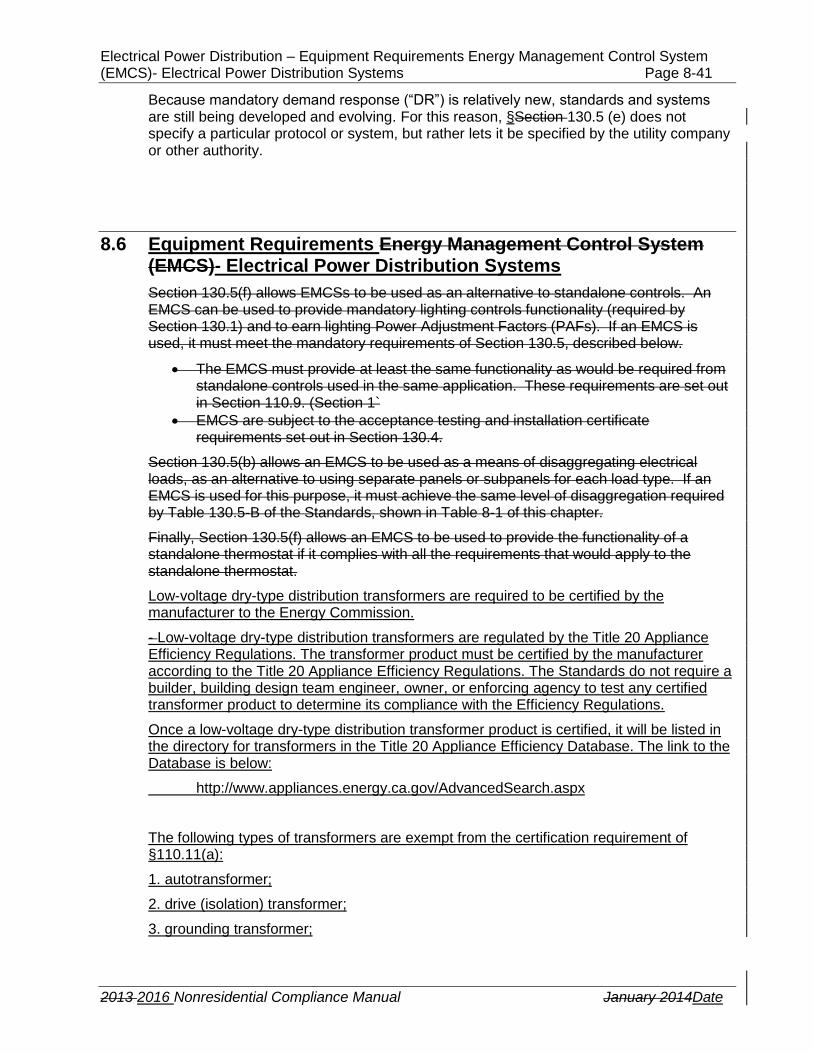
Electrical Power Distribution – Equipment Requirements Energy Management Control System (EMCS)- Electrical Power Distribution Systems Page 8-41
2013 2016 Nonresidential Compliance Manual January 2014Date
Because mandatory demand response (“DR”) is relatively new, standards and systems are still being developed and evolving. For this reason, §Section 130.5 (e) does not specify a particular protocol or system, but rather lets it be specified by the utility company or other authority.
8.6 Equipment Requirements Energy Management Control System (EMCS)- Electrical Power Distribution Systems
Section 130.5(f) allows EMCSs to be used as an alternative to standalone controls. An EMCS can be used to provide mandatory lighting controls functionality (required by Section 130.1) and to earn lighting Power Adjustment Factors (PAFs). If an EMCS is used, it must meet the mandatory requirements of Section 130.5, described below.
The EMCS must provide at least the same functionality as would be required from standalone controls used in the same application. These requirements are set out in Section 110.9. (Section 1`
EMCS are subject to the acceptance testing and installation certificate requirements set out in Section 130.4.
Section 130.5(b) allows an EMCS to be used as a means of disaggregating electrical loads, as an alternative to using separate panels or subpanels for each load type. If an EMCS is used for this purpose, it must achieve the same level of disaggregation required by Table 130.5-B of the Standards, shown in Table 8-1 of this chapter.
Finally, Section 130.5(f) allows an EMCS to be used to provide the functionality of a standalone thermostat if it complies with all the requirements that would apply to the standalone thermostat.
Low-voltage dry-type distribution transformers are required to be certified by the manufacturer to the Energy Commission.
- Low-voltage dry-type distribution transformers are regulated by the Title 20 Appliance Efficiency Regulations. The transformer product must be certified by the manufacturer according to the Title 20 Appliance Efficiency Regulations. The Standards do not require a builder, building design team engineer, owner, or enforcing agency to test any certified transformer product to determine its compliance with the Efficiency Regulations.
Once a low-voltage dry-type distribution transformer product is certified, it will be listed in the directory for transformers in the Title 20 Appliance Efficiency Database. The link to the Database is below:
http://www.appliances.energy.ca.gov/AdvancedSearch.aspx
The following types of transformers are exempt from the certification requirement of §110.11(a):
1. autotransformer;
2. drive (isolation) transformer;
3. grounding transformer;
Page 8-42 Electrical Power Distribution
2013 2016 Nonresidential Compliance Manual January 2014Date
4. machine-tool (control) transformer;
5. nonventilated transformer;
6. rectifier transformer;
7. regulating transformer;
8. sealed transformer;
9. special-impedance transformer;
10. testing transformer;
11. transformer with tap range of 20 percent or more;
12. uninterruptible power supply transformer; or
13. welding transformer.

Electrical Power Distribution – Additions and Alterations Page 8-43
2013 2016 Nonresidential Compliance Manual January 2014Date
8.7 Additions and Alterations
Efforts have been undertaken in the 2016 update of the Standards to clarify the requirements for additions and alterations of electrical power distribution systems.
Although electrical power distribution systems are not specifically covered by the prescriptive requirements for alterations in Section 141.0(b), they are covered under the blanket requirement that:
The altered components of…any newly installed equipment serving the alteration, shall meet the applicable requirements of Sections 110.0 through 110.9, Sections 120.0 through 120.6, and Sections 120.8 through 139130.5
Section 130.5(b)2
Alterations to electrical power distribution systems shall meet the applicable requirements of §130.5 as follows:
1. Service Electrical Metering - New or replacement electrical service equipment shall meet the requirements of §130.5(a) applicable to the electrical power distribution system altered.
2. Separation of Electrical Circuits for Electrical Energy Monitoring - For entirely new or complete replacement of electrical power distribution systems, the entire system shall meet the applicable requirements of §130.5(b).
3. Voltage Drop - Alterations of feeders and branch circuits where the alteration includes addition, modification, or replacement of both feeders and branch circuits, the altered circuits shall meet the requirements of §130.5(c)
EXCEPTION: Voltage drop permitted by California Electrical Code Sections 647.4, 695.6 and 695.7.
4. Circuit Controls for 120-Volt Receptacles and Controlled Receptacles - For entirely new or complete replacement of electrical power distribution systems, the entire system shall meet the applicable requirements of §130.5(d).
8.7.1 Alterations to Service Electrical Metering
If a service is newly added or if the existing service is replaced, the newly added or replaced service must have an electrical metering system which meets the requirements of §130.5(a).
Note that this requirement applies only to the service and does not apply to new or replaced feeders.
8.7.2 Alterations Requiring Separation of Electrical Circuits for Electrical Energy Monitoring
If the electrical power distribution system in the building is entirely new or completely replaced, the entire system within the building must meet the requirements for separation of electrical circuits in §130.5(b) of the Standards. “Entirely new or completely replaced” means that all electrical power distribution components within the building are new. The components that make up an electrical power distribution system include but are not limited to the following:
1. service 2. panel boards 3. feeders

Page 8-44 Electrical Power Distribution
2013 2016 Nonresidential Compliance Manual January 2014Date
4. branch circuit wiring 5. motor control centers 6. switchboards 7. transformers 8. receptacles
If the electrical power distribution system is not entirely new, separation of electrical circuits is not required.
8.7.3 Alterations Triggering Voltage Drop Requirements
Alterations to feeders and branch circuits must meet the voltage drop requirements in §130.5(c), under the following scenarios:
1. Newly added feeders or branch circuits 2. Modification of existing feeders or branch circuits 3. Replacing existing feeders or branch circuits
Note: this requirement is only triggered when both feeders and branch circuits are altered. For example, if a branch circuit is replaced however the feeder to the panel board is not touched, the feeder and branch circuit would not need to meet the 5 percent maximum voltage drop requirement.
Additionally, voltage drop permitted by California Electrical Code Sections 647.4, 695.6 and 695.7, is exempt from this requirement.
8.7.4 Alterations Triggering Circuit Controls for 120-Volt Receptacles and Controlled Receptacles
If the electrical power distribution system in the building is entirely new or completely replaced, the entire system within the building must meet the controlled receptacle requirements in §130.5(b) of the Energy Standards. “Entirely new or completely replaced” means that all electrical power distribution components within the building are new. The components that make up an electrical power distribution system include but are not limited to the following:
1. service 2. panel boards 3. feeders 4. branch circuit wiring 5. motor control centers 6. switchboards 7. transformers 8. receptacles
If the electrical power distribution system is not entirely new, controlled receptacles are not required.

Electrical Power Distribution – Additions and Alterations Page 8-45
2013 2016 Nonresidential Compliance Manual January 2014Date
Example 8-10
Service Electrical requirement for Alterations, §141.0(b)2Pi
I have an existing building with multiple tenant spaces and each individual tenant space is served by separate and individual feeders. I am breaking up one large tenant space into two smaller ones. I plan to reuse the existing feeder and also to add a new feeder. Is it mandatory to provide a meter for the new feeder?
Complying with §141.0(b)2Pi§
This subsection requirement is limited to new or replacement electrical service equipment only and it does not apply to feeders. For alterations involving new or replacement feeders, there is no requirement to install a meters for the newly added or replaced feeder.
Example 8-11
Separation of Electrical Circuits for Alterations, §141.0(b)2Pii
Does the language “entirely new or complete replacement” in §141.0(b)2Pii refer to the entire building or just the altered areas of the building?
Complying with §141.0(b)2Pii§
This requirement of the Energy Standards is for an entirely new or complete replacement of the electrical power distribution system within the entire building. A partial or minor modification of the electrical power distribution system does not trigger the requirement. For example, the scope of work for a first time tenant or undeveloped space does not involve entirely new or complete replacement of the electrical power distribution system, therefore separation of electrical circuits is not required.
Example 8-12
Circuit Controls for 120-Volt Receptacles and Controlled Receptacles requirement for Alterations, §141.0(b)2Piv
Does the language the “entirely new or complete replacement” in §141.0(b)2Piv refer to the entire building or just the altered areas of the building?
Complying with §141.0(b)2Piv§
This requirement is for an entirely new or complete replacement of electrical power distribution system within the entire building. A partial or minor modification of the electrical power distribution system including some new circuits does not trigger the requirement.
Only newly installed electrical power distribution equipment serving the area being altered is subject to the Standards. This means that if the equipment serves the altered area but is not located in the altered area, it must still comply. Any equipment that remains in place during the alteration, or is removed and reinstalled, is not subject to any of the requirements of the Standards.
In terms of the specific items of electrical equipment newly installed in an alteration project, the following requirements apply:

Page 8-46 Electrical Power Distribution
2013 2016 Nonresidential Compliance Manual January 2014Date
A. New electrical services, switchboards, panelboards, motor control centers, and subpanels
Each incoming electrical service must be fitted with a meter as set out in Section 130.5(a), if the service itself is new OR if an existing service supplies a new switchboard, panelboard or motor control center. Loads must be disaggregated into their separate load types as set out in Section 130.5(b) (see Section 8.1.2B above).
B. Feeders and Branch Circuits
New conductors must meet the voltage drop requirements set out in Section 130.5(c) of the Standards (see Section 8.1.2C above). Existing conductors are not subject to these requirements.
New conductors must also be disaggregated as set out in Section 130.5(b). This means that any circuit that has an overcurrent protection device rated at less than 60A must be supplied by a panelboard or subpanel that supplies only loads of that same type, as set out in Table 130.5-B of the Standards (shown in Table 8-1Table 8-1 of this chapter).
C. Receptacles
If new controlled receptacles are added, they must be equipped with automatic shut-off controls, and they must be permanently marked as being controllable. These requirements are set out in Sections 130.5(d)1 and 3.
If new uncontrolled receptacles are added, they are not subject to the requirements of Part 6 of the Standards.
D. Energy Management Control System (EMCSs)
Newly installed EMCS systems must comply with the requirements of Sections 110.9 and 130.4 (see Section 8.68.7 above) if they are installed to comply with mandatory controls requirements triggered by the alteration project, under Section 141.0(b)2 of the Standards.
If additional functionality is added to an existing EMCS system, this would not be subject to any of the requirements of the Standards, because it is not “newly installed equipment” per Section 141.0(b).
8.8 Electrical Power Distribution Systems Compliance Documents
8.8.1 Overview
This section describes the compliance documentation (compliance form(s)) recommended for compliance with the requirements of the 2013 2016 Standards in regards to electrical power distribution systems.
Documents for compliance with the 2013 requirements are proposed to change as follows:

Electrical Power Distribution – Electrical Power Distribution Systems Compliance Documents Page 8-47
2013 2016 Nonresidential Compliance Manual January 2014Date
A. For the period of January 1 through December 31, 2014, compliance documents are proposed to be similar to the 2008 compliance documents, except they have been updated to reflect changes in the 2013 Standards.
B. Starting on January 1, 2015, the Energy Commission proposes to have developed electronic compliance documents to replace existing nonresidential paper documents.
8.8.2 Submitting Compliance Documentation
At the time a building permit application is submitted to the enforcement agency, the applicant also submits plans and energy compliance documentation. This section describes the recommended compliance documentation (forms) for complying with the requirements of the Standards. It does not describe the details of the requirements.
This section is addressed to the person preparing construction and compliance documents, and to the enforcement agency plan checkers who are examining those documents for compliance with the Energy Standards.
8.8.3 Varying Number of Rows per Document
The paper prescriptive compliance documents have a limited number of rows per section for entering data. Some designs may need fewer rows, and some designs may need additional rows. If additional rows are required for a particular design, then multiple copies of that page may be used.
8.8.48.8.2 Compliance Documentation and Numbering
List of compliance documents for electrical power distribution systems:
NRCC-ELC-01-E,; Certificate of Compliance;.ElectricalCompliance, Electrical Power Distribution Systems
NRCI-ELC-01-E, Certificate of Installation, Electrical Power Distribution Systems
There are no acceptance test forms for electrical power distribution systems because there are no required acceptance tests for electrical power distribution systems under the Energy Standards.
The Ffollowing is an explanationthe numbering scheme of the 2013 nonresidential compliance documentation forms numbering:
NRCC Nonresidential Certificate of Compliance
NRCA Nonresidential Certificate of Acceptance
NRCI Nonresidential Certificate of Installation
-ELC Electrical power distribution systems
-01 The first set of compliance documents in this sequence
E Primarily used by enforcement authority

Page 8-48 Electrical Power Distribution
2013 2016 Nonresidential Compliance Manual January 2014Date
-A Primarily used by acceptance tester
Use a single compliance form for each building for the permit application; this is to ensure clarity of information for the permit and plan check process.
The paper prescriptive compliance documents have a limited number of rows per section for entering data. If additional spaces are required on the form in order to include the required information about the project, multiple copies of that page(s) may be used.
Certificate of Compliance Documents
For electrical power distribution systems, there is only one compliance form :
NRCC-ELC-01-E; Certificate of Compliance;.Electrical Power Distribution Systems
8.8.5 Instructions for Completing Electrical Power Distribution Systems Certificate of Compliance
This document has seven pages. Each pageCertification of Compliance must be included as part of the construction document and appear on the electrical drawing plans must appear on the plans (usually near the front of the electrical drawings), and must be accompanied by a voltage drop calculation worksheet. A copy of these documents should also be submitted to the enforcement agency along with the rest of the compliance submittal at the time of building permit application.
The engineer may provide the voltage drop worksheet in whatevercalculation document in format is convenient to them, and is accepted by the inspector. No form has been prescribed for the voltage drop worksheet, because of the wide variety of different, valid, assumptions and unusual variations that the calculations may need to include.
With enforcement agency approval, the applicant may use alternative formats of these documents (rather than the official Energy Commission documents), provided the information is the same and in a similar format.
Project Description
Project Name is the title of the project, as shown on the plans and known to the enforcement agency.
Date is the date of preparation of the compliance submittal package. It should be on or after the date of the plans, and on or before the date of the building permit application.
Project Address is the address of the project as shown on the plans and as known to the enforcement agency.
Climate Zone is the California climate zone in which the project is located. See Reference Joint Appendix JA2 for a listing of climate zones.
Building CFA is the total conditioned floor area of the building as defined in §100.1(b). For additions, the total conditioned floor area is the total area of the addition alone. For alterations, the total conditioned floor area refers to only to the altered floor area.
Unconditioned Floor Area is the total floor area of unconditioned space, as defined in §100.1(b). For additions, the total unconditioned floor area refers to the addition alone. For alterations, the total unconditioned floor area refers to the altered floor area.
Electrical Power Distribution – Electrical Power Distribution Systems Compliance Documents Page 8-49
2013 2016 Nonresidential Compliance Manual January 2014Date
General Information
“Building Type” is specified because there are special requirements for high-rise residential and hotel/motel guest room occupancies. All other occupancies that fall under the Nonresidential Standards are designated “Nonresidential” including schools. It is possible for a building to include more than one building type. See §100.1(b) for the formal definitions of these occupancies. All appropriate boxes shall be checked:
Nonresidential if the project includes nonresidential indoor lighting.
High-Rise Residential if the project includes common areas of a high-rise residential building. Common areas are any interior areas which are not dwelling units. If this project also includes dwelling units, the residential lighting compliance documentation must also be completed and submitted.
Hotel/Motel if the project includes common areas in a hotel or motel. Common areas of a hotel/motel include any interior areas which are not dwelling units. If the project also includes dwelling units, the low-rise residential lighting compliance documentation must also be completed and submitted.
Schools, which includes relocatable buildings on the school site.
Conditioned Spaces as defined in §100.1(b).
Unconditioned Spaces as defined in §100.1(b).
“Phase of Construction “indicates the status of the building project described in the compliance documents.
New construction should be checked for all newly constructed buildings, newly conditioned space or for new construction to existing buildings (tenant improvements).
Addition should be checked for an addition that is not treated as a stand-alone building.
Alteration should be checked for alterations to an existing building lighting system in accordance with §141.0(b). This includes Lighting System Alterations in accordance with §141.0(b)I(ii); and Luminaire Modifications-in-Place in accordance with §141.0(b)I(iii).Tenant improvements are usually alterations.
“Method of Compliance” indicates the method of compliance used for the project.
Complete Building Method—see section 5.7.1 of this chapter for additional information.
Area Category Method—see section 5.7.2 of this chapter for additional information
Tailored Method—see section 5.7.3 of this chapter for additional information
Documentation Author’s Declaration Statement
The “documentation author” is the person who prepares a Title 24 Part 6 compliance document that must subsequently be reviewed and signed by a responsible person (see below) in order to certify compliance with Part 6. Subject to the requirements of §10-103(a)1 and §10-103(a)2, the person who prepares the Certificate of Compliance documents (documentation authors) shall sign a declaration statement on the documents they prepare to certify the information provided on the documentation is accurate and complete.

Page 8-50 Electrical Power Distribution
2013 2016 Nonresidential Compliance Manual January 2014Date
A documentation author may have additional certifications such as an Energy Analyst or a Certified Energy Plans Examiner certification number. Enter number in the EA# or CEPE# box, if applicable.
The person’s telephone number is given to facilitate response to any questions that arise.
Responsible Person’s Declaration Statement
The “responsible person” signing the Certificate of Compliance is required to be eligible under Division 3 of the Business and Professions Code to accept responsibility for the building design, to certify conformance with Part 6. If more than one person has responsibility for the building design, each person (such as an eligible lighting designer) shall sign the Certificate of Compliance document(s) applicable to that portion of the design for which the person is responsible. Alternatively, the person with chief responsibility for the building design shall prepare and sign the Certificate of Compliance document(s) for the entire building design.
The person’s telephone number is given to facilitate response to any questions that arise.
8.8.6 Section A: Electrical Service Electrical Metering
This table allows the location and rating of each electrical service to be recorded, so the inspector can check that appropriate metering is provided, according to Section §130.5(a).
Each row should contain a separate electrical service. All newly installed services must be included, whether the project is a new construction project or an alteration. Also, existing electrical services must be included if the switchboard or panel they supply has been newly installed.
Each column should be filled out as follows:
Indicate The the unique description, location or designation of this the electrical service under Column A
Indicate The the power electrical service rating of the service, in Volt-Amps, under Column B.
Check this columnColumn C if the meter metering installed on this electrical service records the instantaneous (at the time) kW demand on the service
Check this columnColumn D if the meter metering records historical peak demand (kW)
Check this columnColumn E if the meter metering allows the total energy consumption value (kWh) to be reset at the metertracking kWh for a user definable period.
Check this columnColumn F if the meter metering records the energy consumption of the service, broken down according to how much energy was used during each utility rate period (for instance, on-peak vs. off-peak).
Check Column G when utility metering is available and installed at the building.

Electrical Power Distribution – Electrical Power Distribution Systems Compliance Documents Page 8-51
2013 2016 Nonresidential Compliance Manual January 2014Date
The inspector should check either the “pass” or “fail” box depending on whether the capabilities of the meter on this service meet the requirements of Section 130.5(a), set out in the table below the service schedule..
Below the electrical service schedule, Table 130.5-A from the Standards is reproduced, for ease of reference. This table sets out which metering requirements apply, depending on the size (rating) of the service.
8.8.7 Section B: Disaggregation Separation of Electrical Circuits for Energy Monitoring
There are two ways to comply with the disaggregation requirement of the Standards, set out in Section 130.5(b). The first is to ensure that each feeder supplies only one type of load (subject to the additions and exceptions shown in Table 130.5-B of the Standards). The second is to provide a permanently installed load measurement system that can separately record each type of load, using current transformers. The Certificate of Compliance allows the designer Responsible Person to indicate which method of compliance is being used in meeting §130.5(b) requirement. There are several compliance methods permitted to meet the separation of electrical circuit requirement as indicated in Section 8.3. Refer to Section 8.3 for the compliance method allowed. The Responsible Person shall provide information offor the electrical power distribution system in Section B of .

Page 8-52 Electrical Power Distribution
2013 2016 Nonresidential Compliance Manual January 2014Date
Whichever method of compliance is used, the degree to which each feeder or load must be disaggregated depends on the rating of the electrical service that serves it. For larger services, more disaggregation is required. These requirements are set out in Table 130.5-B of the Standards, which is reproduced in the Certificate of Compliance for ease of reference.
The table allows each switchboard, panelboard, motor control center or subpanel to be recorded on a separate row. The columns should be filled out as follows:
A. The unique description, location or designation of this switchboard, panelboards, motor control center or subpanel
B. The unique description, location or designation of the electrical service that supplies it.
C. The power rating of the service, in Volt-Amps
D. The inspector should check either the “pass” or “fail” box depending on whether the feeder to this panel supplies ONLY the type(s) of load described in the relevant cell of the table. Note that:
a. In some cases the table states that there is no disaggregation requirement for that combination of load and service rating
b. in some cases (such as with plug loads) there are additional limits on how much load or how much area may be served by a single feeder.
If, instead of disaggregated panels and feeders, a permanently installed load measurement system is installed that meets the requirements set out in the table, then the inspector should check the box in the bottom row of the table.
8.8.8 Section C: Voltage Drop
Because there are several valid ways to perform voltage drop calculations, depending n how much is known about the location and type of the loads that will be installed, this section of the Certificate of Compliance simply requires that the engineer attach a calculation worksheet document showing voltage drop calculations that comply with the maximum voltage drops allowed by Section §130.5(c) of Standards (23% for feeders, 32% for branch circuits5% percent for the combined voltage drop of the feeder and branch circuit, at design load).
The inspector should check either the “pass” or “fail” box, depending on whether the calculations of the worksheet adequately show that the voltage drops will be within the requirements of the Standards.
For ease of reference, the tables for typical power factor of loads, and for maximum length of typical feeders and branch circuits are shown, reproduced from this chapter of the Compliance Manual.
8.8.9 Section D: Circuit Controls for 120-Volt Receptacles and Controlled Receptacles
This section allows the building inspector to check off whetherdocuments how thehow the controlled receptacles meet the requirements of Section 130.5(e) of the Standards.