
Table of Contents - Blog | ISA Interchange · PDF file · 2017-10-12Table of...
45
Transcript of Table of Contents - Blog | ISA Interchange · PDF file · 2017-10-12Table of...
1
Table of Contents
Cover Control Systems Engineer (CSE) ................................................................................................ i Notice from the Publisher .................................................................................................................... iii This Reference Manual Covers All Subject Content for the PE/CSE Examination ............................... iv Plan Your Study Time ........................................................................................................................... iv
Table of Contents .................................................................................................................................... 1
Introduction to This Study Guide ........................................................................................................ 19 About the Author ................................................................................................................................ 19 People who have contributed to the previous editions of this manual ............................................. 20
Tips on How to Use This Study Guide ................................................................................................ 21 Using Thumbnails to Navigate ............................................................................................................ 22 Using Bookmarks to Navigate ............................................................................................................. 23 Important File Attachments - Open by clicking on the paper clip! ..................................................... 24 How to Print this Manual .................................................................................................................... 24
Welcome to Control Systems Engineering ........................................................................................ 25 Licensing as Professional Engineer / Control Systems Engineer (CSE) ................................................ 25 Why Become a Professional Engineer? ............................................................................................... 28 This is the third edition of this study manual...................................................................................... 30 The new and expanded sections include: ........................................................................................... 30
Recommended Flow Chart of Study for the CSE ............................................................................... 31 Overview of Recommended Flow Chart of Study for the CSE ............................................................ 32
Examination General Information........................................................................................................ 33 State Licensing Requirements ............................................................................................................. 33 Eligibility .............................................................................................................................................. 33 Exam schedule..................................................................................................................................... 33 Description of Examination ................................................................................................................. 34 Exam content ...................................................................................................................................... 34
I. Measurement ............................................................................................................................ 34 II. Signals, Transmission, and Networking ..................................................................................... 35III. Final Control Elements .............................................................................................................. 35IV. Control Systems ........................................................................................................................ 36V. Safety Systems .......................................................................................................................... 37 VI. Codes, Standards, Regulations ................................................................................................. 37
Exam Scoring ....................................................................................................................................... 37
Reference Materials for the Exam ....................................................................................................... 39 Recommended Books and Materials to Take to the Exam ................................................................. 39Books and Materials for Testing ......................................................................................................... 40 Books for Additional Study ................................................................................................................. 40Courses for Additional Study .............................................................................................................. 41ISA Control Systems Engineer (CSE) PE Review .................................................................................. 41 Industrial Network Training ................................................................................................................ 41 Control Systems Engineer (CSE) Supplement Course ......................................................................... 42 Online Process Plant @ Learn Control Systems.com .......................................................................... 42
2
Process Measurement Standards and Terminology ......................................................................... 43 Overview of process measurement, control and calibration ............................................................. 43 Process Signal and Calibration Terminology ....................................................................................... 44 Definition of the Range of an Instrument ........................................................................................... 44 Definition of the Span of an Instrument ............................................................................................. 45 Definition of the use of Zero in Instrumentation ................................................................................ 45
Live-Zero ........................................................................................................................................ 45 Elevated-Zero ................................................................................................................................. 45 Suppressed-Zero ............................................................................................................................ 45
Illustrations of range and span terminology ....................................................................................... 46 Illustrations of measured variable, measured signal, range and span ............................................... 47
Applications of Fluid Mechanics in Process Control ........................................................................ 49 Relationship of pressure and flow ...................................................................................................... 49 Applications of the formulas ............................................................................................................... 52 Summary of fluid mechanics for process control ............................................................................... 56
Temperature Measurement and Calibration ....................................................................................... 57 Temperature measurement devices and calibration .......................................................................... 57 Thermocouple - worked examples (how to read the thermocouple tables) ...................................... 59 RTD (Resistance Temperature Detector) ............................................................................................ 60 Installing RTDs and Thermocouples into a process stream ................................................................ 63 Typical RTD and thermocouple applications ....................................................................................... 64
Pressure Measurement and Calibration ............................................................................................. 65 Pressure measurement and head pressure ........................................................................................ 65 Applying pressure measurement and signals - worked examples ...................................................... 66 Differential pressure and meter calibration ....................................................................................... 66 Pressure change in a pipe for a given flow rate .................................................................................. 67 Pressure change across the flow element for a given flow rate ......................................................... 67 Pressure calibration of transmitter ..................................................................................................... 68
Level Measurement and Calibration.................................................................................................... 69 Applying level measurement and calibration - Worked examples ..................................................... 69 Level displacer (Buoyancy) .................................................................................................................. 72 Bubbler level measurement ................................................................................................................ 74 Density measurement ......................................................................................................................... 75 Interface level measurement .............................................................................................................. 76 Radar and Ultrasonic level measurement ........................................................................................... 78
Time of flight technology ............................................................................................................... 78 Ultrasonic level measurement ....................................................................................................... 78 Radar (non-contact) ....................................................................................................................... 78 Guided Wave Radar (GWR) ............................................................................................................ 79
Capacitance level measurement ........................................................................................................ 79 Radiometric (gamma) level measurement ......................................................................................... 80 Level gauging system in a tank farm .................................................................................................. 80 Calculating the volume in tanks .......................................................................................................... 81
Flow Measurement and Calibration..................................................................................................... 83 Applying flow measurement devices .................................................................................................. 83 Turndown ratio in a flow meter .......................................................................................................... 83 ISA standard flow meter symbols ....................................................................................................... 83Flow meter applications chart ............................................................................................................ 84
3
Pressure tappings (Impulse Line Taps) ................................................................................................ 84 Orifice tap dimensions and impulse line connections ........................................................................ 85 Various Types of Flow Meters ............................................................................................................. 88 Applying the Bernoulli principle for flow control ................................................................................ 89 Types of Head Pressure based meters ................................................................................................ 90
Venturi meter................................................................................................................................. 90 ISO 5167 Orifice Plate and Orifice plate ......................................................................................... 90Dall tube ......................................................................................................................................... 90 Pitot-Static tube ............................................................................................................................. 90 Multi-hole pressure probe ............................................................................................................. 90 Cone meters ................................................................................................................................... 90 Annubar meters (also reference averaging pitot tubes) ............................................................... 91
Differential head meter calculations................................................................................................... 91 Classic fluid mechanics model ............................................................................................................. 91
“K” value flow coefficients ............................................................................................................. 92 The beta ratio ...................................................................................................................................... 95
Pipe Size Is Important - Remember! .............................................................................................. 96 Standard Flow Measurement Equations ............................................................................................. 97 Spink - Flow Measurement Equation .................................................................................................. 97
The basic Spink equation derived .................................................................................................. 98 The basic Spink equation for liquid ................................................................................................ 99 The basic Spink equation for gas and vapor .................................................................................. 99 The basic Spink equation for steam ............................................................................................... 99
Applications of the Beta and Spink factors ............................................................................... 100 Table 3 – The Spink Factor (S) ........................................................................................................... 101 ISO 5167 - Flow Measurement Equation .......................................................................................... 102
The expansibility factor ................................................................................................................ 102 The discharge coefficient ............................................................................................................. 103 The ISO 5167 equation explained ................................................................................................ 103 Solve for the Reynolds number ‘Re’ ............................................................................................ 104 Solve for the coefficient ‘C’ .......................................................................................................... 104 Solve for mass flow rate: ............................................................................................................. 105 Solve for volumetric flow rate ..................................................................................................... 105 Equation Comparison Summary .................................................................................................. 106
Sizing orifice type devices for flow measurement - worked examples ............................................. 106 Mass flow measurement and control ............................................................................................... 109 Applying mass flow measurement with an orifice - worked example .............................................. 112 Turbine meter applications ............................................................................................................... 113
Turbine flow meter - worked example ........................................................................................ 116
Weight Measurement and Calibration ............................................................................................... 119 Weight measurement devices and calibration ................................................................................. 119 Load cells ........................................................................................................................................... 119 Load cells for (flow, level, force) applications in process ................................................................. 120
Process Analyzers .............................................................................................................................. 121 Electrical conductivity and pH correction ......................................................................................... 121How are pH and electrical conductivity measured? ......................................................................... 121 Control of pH values in processes ..................................................................................................... 121
Typical pH correction control scheme ......................................................................................... 122 Control of conductivity ...................................................................................................................... 123
Instrument specifications and operating parameters ................................................................. 123

4
Common Plant Analyzers .................................................................................................................. 123 Boiling Point Analyzers ................................................................................................................. 123 Vacuum Distillation Analyzer ....................................................................................................... 123 Flash Point Analyzer ..................................................................................................................... 124 Cloud Point Analyzer .................................................................................................................... 124 Freeze Point Analyzer .................................................................................................................. 124 Pour Point Analyzer ..................................................................................................................... 124 Color Analyzer .............................................................................................................................. 124
Combustion and Analyzers ................................................................................................................ 124 Combustion furnace and air-fuel ratio control ............................................................................ 125 Air-Fuel ratio control utilizing CO and O2 concentrations ........................................................... 125 BMS - Burner Management Safety .............................................................................................. 125 OSHA Requirements .................................................................................................................... 125 Carbon dioxide (CO2) reading ...................................................................................................... 126
Examples of Process Analyzers ......................................................................................................... 126 Select the appropriate analyzer and configuration .......................................................................... 127 Typical Analyzer Piping and Control Schematic ................................................................................ 128
Process Control Valves and Actuators ............................................................................................. 129 Process control valves ....................................................................................................................... 129 Considerations when sizing a control valve ...................................................................................... 130
Flow Coefficient Cv ...................................................................................................................... 130 Specific Gravity ............................................................................................................................ 130 Operating Conditions ................................................................................................................... 130
ISA standard valve symbols ............................................................................................................... 131 ISA standard pressure regulating valve symbols............................................................................... 131 Valve actuators.................................................................................................................................. 132
ISA standard actuator symbols .................................................................................................... 132 Limit switches on a valve - ISA standard symbol .............................................................................. 133
Calculating the size of the actuator ............................................................................................. 133 Example actuator sizing ............................................................................................................... 134
Split ranging control valves ............................................................................................................... 135 Valve positioner applications ............................................................................................................ 137
ISA standard valve positioner symbols ........................................................................................ 137 Summary of positioners ............................................................................................................... 138 When should a positioner be used? ............................................................................................ 138 Electrical positioners .................................................................................................................... 138
Control valve application comparison chart ..................................................................................... 139 Understanding flow with valve characteristics ................................................................................. 140
What is the ΔP for valve sizing? ................................................................................................... 140 System piping ΔP pressure drops................................................................................................. 140 Control valve ΔP pressure drop ................................................................................................... 141 Graph of the Inherent valve characteristics (off the shelf) .......................................................... 142 Which valve characteristic trim to use? ....................................................................................... 142 Characteristic distortion in valves ................................................................................................ 143 Gain and Rangeability (turndown ratio in valves) ....................................................................... 145
Proper control valve sizing ............................................................................................................ 146 Oversized valves present problems ............................................................................................. 147 Experiment and understand Installed valve characteristics ........................................................ 149 Summary of control valve characteristics .................................................................................... 150
Control Valve Sizing ........................................................................................................................... 151 The Valve Sizing Equations .......................................................................................................... 151
5
The Basic equation for liquid flow ............................................................................................... 151 The basic equation for gas flow ................................................................................................... 151 The basic equation for steam flow .............................................................................................. 151
Sizing valves for liquid - worked example ......................................................................................... 153 Sizing valves for gas - worked example ............................................................................................. 155 Sizing valves for vapor and steam - worked example ....................................................................... 158 Sizing valves for two phase flow - worked example ......................................................................... 161
Two Phase Flow Worked Example ............................................................................................... 163 ΔP Valve Limitations - Very Important! ............................................................................................ 165
Flowing Quantity (the turndown ratio of a valve) ....................................................................... 165 Flashing ........................................................................................................................................ 166 Joule-Thomson Effect (J-T) – auto refrigeration in valves ........................................................... 166 Choked Flow ................................................................................................................................. 166
Maximum ΔP and Maximum Flow (qmax) in Valves Applications ...................................................... 167 Determining qmax (Maximum Flow Rate) ..................................................................................... 167
Determining ΔPmax (the Allowable Sizing Pressure Drop) ............................................................ 168 Cavitation in valves ...................................................................................................................... 169
Check for cavitation and choked flow in a control valves - worked examples ................................. 170 Fluid Velocities through Control Valves ............................................................................................ 174 Viscosity Correction for Sizing Valves ............................................................................................... 175
Pressure Relief Valves and Rupture Disks ....................................................................................... 177 Pressure Relief Valves (PRV) and Pressure Safety Valves (PSV) ........................................................ 177
Important Note: (Do Not Throttle Pressure Relief Valves) .......................................................... 177 EPA regulations ............................................................................................................................ 178 Regulation details ........................................................................................................................ 178 PRD bypass ................................................................................................................................... 179 Pilot operated safety valve .......................................................................................................... 180 Bellow or balanced bellow and diaphragm ................................................................................. 181 Weight loaded PRV operation ..................................................................................................... 181
Venting Atmospheric and Low-Pressure Storage Tanks ................................................................... 183 API Standards for pressure relieving systems ................................................................................... 186 CFR Standards for pressure relief required by federal law ............................................................... 187
API Standard 2000 – Venting atmospheric and low-pressure storage tanks .............................. 187 API Standard 2003 – Protection against ignitions from static, lightning, and stray currents ...... 188 API Standard 2350 – Overfill protection for storage tanks in petroleum facilities ...................... 188 API Standard 2510 – Design and construction of LPG installations ............................................. 189 NFPA 30 – Flammable and combustible liquids code .................................................................. 190
Important excerpts from NFPA 30 code: .................................................................................. 190 Chapter 4: Tanks Storage .......................................................................................................... 190 Chapter 5: Piping Systems ......................................................................................................... 191 Chapter 6: Container and Portable Storage Tanks .................................................................... 191 Chapter 7: Operations ............................................................................................................... 192
ASME VIII code for sizing relief valves and rupture disks ............................................................ 193 Introduction to ASME VIII .......................................................................................................... 195 Overview Section VIII - Pressure Vessels ................................................................................... 195 ASME VIII – Pressure relief requirements ................................................................................. 195 ASME VIII - Pressure limits in sizing ........................................................................................... 196
Table 5 - ASME standard nozzle orifice data ..................................................................................... 196 ISA pressure relief valve and rupture disc symbols .......................................................................... 197 Sizing equations for relief valves and rupture disks ......................................................................... 198
ASME VIII code equations USCS units .......................................................................................... 198

6
A Note about sonic or choked flow ............................................................................................. 199 Variables for PRV and PSV sizing equations ................................................................................. 199
Sizing rupture disks - worked examples ............................................................................................ 201 Sizing pressure relief valves - worked examples ............................................................................... 203
Review of Feedback Control Fundamentals .................................................................................... 209 Compare Open Loop Control to Closed Loop Control ...................................................................... 209 Open Loop Example – A Mathematical Analysis ............................................................................... 209 Closed Loop Example – A Mathematical Analysis ............................................................................. 211 The Transfer Function for the Automobile ....................................................................................... 213
Review of Frequency Response Fundamentals .............................................................................. 215 Electrical Application – A First Order System .................................................................................... 215 Bode Plot of First Order System ........................................................................................................ 216 Calculate the data for the Bode Plot ................................................................................................. 217 Creating a Bode Plot – First Order System using Frequency ............................................................ 220 Hydraulic Application – A First Order System ................................................................................... 221
Process Control Theory and Controller Tuning ............................................................................... 223 Degrees of Freedom in Process Control Systems ............................................................................. 223 Controllers and control strategies (models-modes) ......................................................................... 225 Process Loop Gain (Gp) ..................................................................................................................... 227 Process Signal Linearization .............................................................................................................. 228 Signal Filtering in Process Control ..................................................................................................... 230
Appling Signal Filters .................................................................................................................... 230 Filter Time Constant and Sample Time ........................................................................................ 231 Example of Filter Time Selection ................................................................................................. 232
DCS/PLC Sample and Scan Time Consideration ................................................................................ 233 Sampling time .............................................................................................................................. 233 Time per scan cycle ...................................................................................................................... 233
Tuning of Process Controllers ........................................................................................................... 234 Closed Loop Tuning of the Controller .......................................................................................... 234
Example: Tune Using Ultimate Gain (continuous cycling) ........................................................ 235 Open Loop Tuning of the Controller ............................................................................................ 236
Example: Tuning using Process Reaction Curve (Step Response) ............................................. 238 Advanced Tuning Methods for Controllers ....................................................................................... 239
The Integral Criteria Method ....................................................................................................... 239 Lambda Tuning Concepts ............................................................................................................. 239 Example Reactor Ratio Timing ..................................................................................................... 242 IMC Tuning Method ..................................................................................................................... 243 PID Controller Models .................................................................................................................. 244 Trial and Error Tuning Method .................................................................................................... 244 Dead Time and PID Control .......................................................................................................... 244
PID Tuning Video - Parameters in Action .......................................................................................... 244 Process Characteristics from the transfer function .......................................................................... 245 Poles, Zeros, and Dampening from the Transfer Function ............................................................... 245
Find the Poles from the Function ................................................................................................ 246 Find the Damping from the Function ........................................................................................... 246 Find the Time Constant ................................................................................................................ 247 Find the Period ............................................................................................................................. 247 Find the Time Constant from the Period ..................................................................................... 247 Find Overshoot and Peak Value ................................................................................................... 247
Block Diagram Algebra ...................................................................................................................... 248

7
Example of Block Diagram Algebra Reduction .................................................................................. 249 Nyquist Stability Criterion ................................................................................................................. 250 Routh Stability Criterion .................................................................................................................... 251 Check for Stability using Routh (Example) ........................................................................................ 254
Communications and Industrial Control Networks ......................................................................... 257 Overview of Corporate and Plant Networks ..................................................................................... 257 Open System Interconnect (OSI) and TCP/IP network layer model .................................................. 259
7 Layers of networking in the OSI model ..................................................................................... 259 Physical (Layer 1) ....................................................................................................................... 259 Data Link (Layer 2) ..................................................................................................................... 259 Network (Layer 3) ...................................................................................................................... 259 Transport (Layer 4) .................................................................................................................... 259 Session (Layer 5) ........................................................................................................................ 260 Presentation (Layer 6) ............................................................................................................... 260 Application (Layer 7) ................................................................................................................. 260
Cisco Network Certification – IIOT (Industrial Internet of Things) for IT and OT .............................. 260The typical network model .......................................................................................................... 261 The Network Essentials ................................................................................................................ 263
Overview of Industrial Networks ...................................................................................................... 264 The most popular industrial networks and their applications are below.................................... 264 HART Networks ............................................................................................................................ 265
Traditional HART Network......................................................................................................... 265 A Wired HART Network ............................................................................................................. 266 A Wireless HART Network ......................................................................................................... 266
PROFIBUS and AS-i Networks ...................................................................................................... 267Reasons for choosing PROFIBUS ............................................................................................... 267 PROFIBUS DP ............................................................................................................................. 267 PROFIBUS PA ............................................................................................................................. 268 PROFINET ................................................................................................................................... 268 AS-i ............................................................................................................................................ 268PROFIBUS Fieldbus Message Specification (FMS) ..................................................................... 269 PROFIBUS................................................................................................................................... 269 PROFIsafe .................................................................................................................................. 269PROFIdrive ................................................................................................................................. 269Use of the OSI Networking Layers ............................................................................................. 269 PROFIBUS/AS-i/PROFINET Certifications: ................................................................................. 269
FOUNDATION Fieldbus . ...................................................................................................................... 270Reasons for choosing FOUNDATION Fieldbus . ................................................................................ 270H2 or HSE (High Speed Ethernet) .............................................................................................. 270 FOUNDATION H1 ......................................................................................................................... 270 Typical FOUNDATION Segments ................................................................................................. 271 Use of the OSI Networking Layers ............................................................................................. 271
Rockwell and ODVA (CIP) Networks ............................................................................................ 272 ControlNet ............................................................................................................................. 272 DeviceNet .............................................................................................................................. 273 EtherNet/IP ............................................................................................................................ 274 CompoNet ............................................................................................................................. 274 DH485, DH+, RIO ................................................................................................................... 274
Modbus Networks........................................................................................................................ 275 Traditional Modbus Networks................................................................................................... 275 Communication and Devices ..................................................................................................... 275

8
Protocols.................................................................................................................................... 275 EtherCAT ...................................................................................................................................... 276 SERCOS ......................................................................................................................................... 276 Summary - Automation and Process Control Networks ............................................................. 277 Plant Facility Monitoring and Control System (FMCS) ................................................................ 277BACnet ......................................................................................................................................... 278 LonWorks ..................................................................................................................................... 278 Typical Building Automation Network ......................................................................................... 278 Networked intelligent and smart devices .................................................................................... 279 PID control in intelligent networked devices ............................................................................... 279 PROFIBUS Control Blocks ............................................................................................................. 280 The Rosemount 333 Tri-Loop to split multiple variable signals ................................................... 280
The Application of Digital Logic in Control Systems ...................................................................... 281 Overview of Digital Logic ................................................................................................................... 281 Digital Logic Gate Symbols ................................................................................................................ 281 Digital Logic Gate Truth Tables ......................................................................................................... 282 ISA Binary Logic ................................................................................................................................. 283 Relay Ladder Logic ............................................................................................................................. 284 Standard RLL Symbols ....................................................................................................................... 285 Sealing Circuits .................................................................................................................................. 285 Control System Architectures ........................................................................................................... 286
DCS Plant Wide Control System Architecture - Networked......................................................... 286 PLC Control System Architecture ................................................................................................. 288 PLC (Programmable Logic Controller) vs PAC (Process Automation Controller) ......................... 288 Controller Application Function Comparison Chart ..................................................................... 289 SCADA Control System Architecture ............................................................................................ 289 PLC Programming Languages ....................................................................................................... 290
PLC Programming (LD) ladder diagram or (RLL) relay ladder logic ........................................... 291 PLC Programming (ST) structured text ...................................................................................... 291 PLC Programming (FBD) functional block diagram ................................................................... 292 PLC Programming (SFC) sequential function chart ................................................................... 292
Writing a Program and Developing a HMI for a Small Systems ................................................... 293 RSLogix 5000, ControlLogix PIDE (PID Enhanced) Function Block Diagram ................................. 294
Motor Control and Logic Functions .................................................................................................. 297 Plant Electrical System ...................................................................................................................... 297 Motor Control Center (MCC)............................................................................................................. 297 Typical MCC Design ........................................................................................................................... 298
Typical Motor Controller .............................................................................................................. 298 How to Control a Motor .................................................................................................................... 299
Starter Auxiliary Contacts ............................................................................................................ 299 Overload and Fault ....................................................................................................................... 299
The basic NEMA stop-start station ................................................................................................... 300 Typical Motor Control Schematic ................................................................................................ 300
NEMA and IEC Terminal Designations .............................................................................................. 301 NEMA Standards Publication ICS 19-2002 (R2007) ................................................................... 301 Relays and Contacts .................................................................................................................. 301
Coil Lettering and Relay Socket Numbers (NEMA and IEC Numbers) ......................................... 301 Standard Symbols ....................................................................................................................... 303 Standard Symbols (Continued) .................................................................................................... 304 NEMA and IEC Comparisons ........................................................................................................ 305
9
Stop-Start Station Control Circuit Schematic ............................................................................... 306 Starter Control Circuit Schematic ................................................................................................ 306
Relay Ladder Logic (RLL) and Function Blocks ................................................................................... 307 RLL and Their Boolean Functions ................................................................................................. 307 Putting Ladder Logic into the PLC ................................................................................................ 308 Example of a Safety System in a PLC ............................................................................................ 309 Safety Logic in the PLC ................................................................................................................. 310
Alarming on Sensor Input Failure .............................................................................................. 310 The PLC Logic for Valve and Alarm Monitoring ........................................................................... 311
Schematic to Programming Languages ..................................................................................... 311
The Application of Analog Circuits in Control Systems ................................................................. 313 Overview of Analog Signals ............................................................................................................... 313
Typical Analog Loop Wiring Diagram ........................................................................................... 313 Simplified signal transmitters that maintain constant flow rate for measurement variable ...... 314 Constant Current Loops and Ohm’s Law ..................................................................................... 315 Current Loop Fundamentals ........................................................................................................ 315 The 4-20 mA Current Loop ........................................................................................................... 315 Using Current to Transmit Transducer Data ................................................................................ 316
Current Loop Components ........................................................................................................ 316 Current Loop System ................................................................................................................. 316
Designing a Current Loop System ................................................................................................ 317 Choosing a Power Supply .......................................................................................................... 317
Adding More Transducers and Instruments ................................................................................ 318 Devices in Series ........................................................................................................................ 319
A typical Current Loop Repeater .................................................................................................. 320 Active and Passive Current Loops ................................................................................................ 321 Sinking and Sourcing Devices ....................................................................................................... 322
What is the difference between PNP and NPN? ....................................................................... 322 PNP Sensor verses NPN Sensor ................................................................................................. 323
Overview of Motion Controller Applications .................................................................................... 325 Motion Control Systems.................................................................................................................... 325
The basic architecture of a motion control system contains: ..................................................... 325 Stepper Motor ............................................................................................................................. 325
Closed-Loop Stepper Motor ...................................................................................................... 325 Stepper motor advantages .......................................................................................................... 326
Linear motion control ................................................................................................................ 326 Series vs. parallel connection .................................................................................................... 326
Servo motor systems ................................................................................................................... 327 Advanced motion controls ........................................................................................................ 327 Position plus velocity system .................................................................................................... 327
Electro-hydraulic Servo System ................................................................................................... 328 Position and pressure/force control ......................................................................................... 328 Position transducers .................................................................................................................. 328 Fieldbus interfaces .................................................................................................................... 329
Applications of servo systems ...................................................................................................... 329 Soft Starter Applications ................................................................................................................... 329
How does a soft starter work? ..................................................................................................... 329 Benefits of choosing a soft starter ............................................................................................... 330
Variable Frequency Drive .................................................................................................................. 330 How does a variable frequency drive work? ............................................................................... 330
10
Conversion from AC to DC to AC PWM ........................................................................................ 331 Volts to Hertz Relationship .......................................................................................................... 334 Important Note about Low Frequency in VFDs ........................................................................... 335 VFDs put Noise into the Electrical System ................................................................................... 335 PID Control with VFD or DC Drive ................................................................................................ 336
Closed loop control with drive electronics ................................................................................ 336 Block diagram of PID control with feedback operation available on some VFDs ..................... 336 Drive with built-in PID tension control of web or winding reel operation ................................ 336
Electrical Systems and Power Quality .............................................................................................. 337 Filtering Power and Harmonics ......................................................................................................... 337
Harmonic Neutralizing Transformers........................................................................................... 337 Filtering of a Harmonics in Power Systems .................................................................................. 338 Passive Filter ................................................................................................................................ 338 Active Filter .................................................................................................................................. 339
Proper Grounding Procedures .......................................................................................................... 341
Emergency Standby Systems ............................................................................................................ 343 Article 700 – Emergency Systems ..................................................................................................... 343 Article 701 – Legally Required Standby Systems .............................................................................. 343 Article 702 – Optional Standby Systems ........................................................................................... 343
UPS (uninterruptible power supply) ............................................................................................ 343 UPS and Battery Bank Sizing ........................................................................................................ 344
Load Profile Calculation ............................................................................................................. 347 Battery Sizing Calculation .......................................................................................................... 348 Worked Example – Sizing the Battery Bank .............................................................................. 349
Backup Generator ........................................................................................................................ 351 BMCS Implementation (Building Monitoring and Controls System) ................................................ 352
Hydraulics and Pneumatics ............................................................................................................... 353 Fluid Power Systems ......................................................................................................................... 353
Hydraulic Systems ........................................................................................................................ 353 Pneumatic Systems ...................................................................................................................... 355 Typical Pneumatic System (this type may be found in a manufacturing or chemical plant) ...... 355
Mechanical Flow Diagram of a Large Compressor .................................................................... 355 Instrumentation Air Header (Fluid Distribution Header or Manifold) ...................................... 355 Pneumatic Schematic of Valve Controller ................................................................................. 356 I/P Current to Pneumatic Positioner ......................................................................................... 356
Instrument Air Cost - Engineering Economics ............................................................................. 357 Assumption .................................................................................................................................. 357 Peak air demand .......................................................................................................................... 357 Vendor data ................................................................................................................................. 357 Include Total Demand .................................................................................................................. 358 Instrument Air Piping and Cost .................................................................................................... 358
Pipe sizing is just like sizing electrical lines ....................................................................................... 359 Caution Using Charts and Graphs ................................................................................................ 359 Interconnects and headers .......................................................................................................... 359 The Target Objectives .................................................................................................................. 359 Eliminate the pressure drop ........................................................................................................ 360 Air Velocity ................................................................................................................................... 360 Crunching the Numbers ............................................................................................................... 361 Recover Wasted Heat to Save Money ......................................................................................... 362

11
Fluid Power Schematic Symbols ....................................................................................................... 363
Overview of Conveying Technologies .............................................................................................. 371 Some common types of conveying systems are as follows: ............................................................. 371
Heavy Duty Roller Conveyors ....................................................................................................... 371 Flexible Conveyors ....................................................................................................................... 371 Vertical Conveyors and Spiral Conveyors .................................................................................... 372 Spiral Conveyors .......................................................................................................................... 372 Vertical conveyor with forks ........................................................................................................ 372 Vibrating Conveyors ..................................................................................................................... 372
Pneumatic and Vacuum Conveyors .................................................................................................. 373 Pneumatic Tube Conveyor Systems ............................................................................................. 373 Large Complex Pneumatic Conveying Systems............................................................................ 374
Typical Plant Pneumatic Conveying System .............................................................................. 374 HMI for Pneumatic Conveying System ...................................................................................... 374 Dilute Phase Systems ................................................................................................................ 375 Dense Phase Systems ................................................................................................................ 375 Conveying Phase Diagram ......................................................................................................... 376 Pressure Distance Relationships ............................................................................................... 377
Vacuum Conveying ...................................................................................................................... 377 A typical vacuum product transportation system ..................................................................... 378 Vacuum conveying systems and HMI display ........................................................................... 378 Vacuum conveying system HMI display .................................................................................... 378
Blower operating cost of pneumatic systems.............................................................................. 379 Screw conveying systems............................................................................................................. 379
Screw conveyor instruments ..................................................................................................... 380 Mass or bulk flow measurement ................................................................................................. 380
Radiometric measurement for mass flow rate ......................................................................... 380 Load cell measurement for mass flow rate ............................................................................... 380
Mass flow control of conveying system ....................................................................................... 381 Radiometric measurement for mass flow rate ......................................................................... 381 Load Cell (Strain Gauge) measurement for mass flow rate ...................................................... 381 Typical scale systems used on manufacturing lines and in plants ............................................ 382
Chemical Process Technology and Equipment ............................................................................... 383 Process Technologies ........................................................................................................................ 383 Separation Processes ........................................................................................................................ 384
A Typical Horizontal 3-Phase Separator ....................................................................................... 384 Industrial Distillation ......................................................................................................................... 384
A Typical Industrial Distillation Process ....................................................................................... 385 A Typical Distillation Unit ............................................................................................................. 385
Industrial Furnaces (Fired Heaters) ................................................................................................... 386 Industrial Furnaces ....................................................................................................................... 386 Fired Heater Control Scheme ....................................................................................................... 387
Expansion Tanks and Heat Transfer Fluid ......................................................................................... 387 Vapor Pressure, Boiling and Cavitation in Equipment ...................................................................... 389
Vaporization in Equipment .......................................................................................................... 389 Control Valve Applications ........................................................................................................... 389 Pumping Applications .................................................................................................................. 389 Video of Vaporization and Cavitation Phenomenon ................................................................... 390
Heat Exchangers ................................................................................................................................ 391 Flow Arrangement ....................................................................................................................... 391 Shell and Tube Heat exchanger ................................................................................................... 392
12
Dynamic scraped surface heat exchanger................................................................................. 392 Phase-change heat exchangers ................................................................................................. 392 Reboiler as seen on a distillation column .................................................................................. 392
Heat Exchanger BTU Calculation and Control .............................................................................. 393 Example of how to control the heat exchanger: ......................................................................... 393
Condenser (heat transfer) ................................................................................................................. 394 Evaporation Processes ...................................................................................................................... 395
What is evaporation? ................................................................................................................... 395 What is latent heat? ..................................................................................................................... 395 What is the boiling point? ............................................................................................................ 395
Various Types of Evaporators and Their Working Principles ............................................................ 395Vertical Falling Film Evaporator ................................................................................................... 395 Horizontal Film Evaporator.......................................................................................................... 396Low Temperature Vacuum Evaporator ........................................................................................ 397
Using the Psychrometric Chart ......................................................................................................... 399 Cooling Towers .................................................................................................................................. 401
Cooling Tower Calculations .......................................................................................................... 401Cooling tower water loss and make-up ....................................................................................... 402
Cooling tower control scheme and operating cost .......................................................................... 404 Typical pH correction system ....................................................................................................... 405
Chemical Reactors and Control ......................................................................................................... 406 What is a Reactor? .................................................................................................................... 406Types of Reactors ...................................................................................................................... 406
Basic Control Scheme for a Reactor ............................................................................................ 407CSTR (Constant Stirred Tank Reactor) ....................................................................................... 407
Hydrocracking Reactor Controls .................................................................................................. 407Chemical Scrubbers ........................................................................................................................... 408
Wet exhaust gas cleaning ............................................................................................................ 408 Wet gas scrubber ......................................................................................................................... 409 Dry scrubbing ............................................................................................................................... 410 Scrubber waste products ............................................................................................................. 410 Bacteria spread ............................................................................................................................ 410
Dehydration Processes ...................................................................................................................... 411 Absorption ................................................................................................................................... 411
Joule-Thompson effect...................................................................................................................... 413 Crystallization Technology ................................................................................................................ 414
Static Crystallization ..................................................................................................................... 414 Falling Film Crystallization ........................................................................................................... 416 Suspension Crystallization ........................................................................................................... 416 Process flow diagram suspension crystallization ......................................................................... 417 Freeze Concentration ................................................................................................................... 417 Overview of a small crystallization plant to control .................................................................... 418
Flare and Vent Disposal Systems ...................................................................................................... 418 Types of flares .............................................................................................................................. 418 Flare Control Systems .................................................................................................................. 419
Quality Control Standards for Production of Products ..................................................................... 419
ISA Standards for Documentation ..................................................................................................... 421 ISA Instrument or Function Symbol .................................................................................................. 421 ISA Line Type Symbols ....................................................................................................................... 422 Standard Line Types .......................................................................................................................... 422ISA Identification Letters ................................................................................................................... 423

13
ISA P&ID Identification (Controllers and Readouts) .......................................................................... 424ISA P&ID Identification (Transmitters, Switches and Alarms) .......................................................... 425ISA P&ID Identification (Compute, Relay and Elements) ................................................................. 426Piping and Equipment Symbols ......................................................................................................... 427 Standard P&ID (Piping and Instrumentation Diagram) ..................................................................... 428
P&ID Sample 1 (Functions) .......................................................................................................... 428 P&ID Sample 2 (Alarms) ............................................................................................................... 429 P&ID Sample 3 (Separator) .......................................................................................................... 429 EM (Equipment Modules) as in the ISA-88 Standard ................................................................... 430Cross Limiting Control of Furnace ................................................................................................ 430Simplified P&ID Sample 1 ............................................................................................................ 431 Simplified P&ID Sample 2 ............................................................................................................ 431
ISA Standard PFD (Piping Flow Diagram) or MFD (Mechanical Flow Diagram) ................................ 432 PFD (Piping Flow Diagram) Sample 1 ........................................................................................... 432
BFD (Block Flow Diagram) ................................................................................................................. 434 BFD Sample 1 ............................................................................................................................... 434 BFD Sample 2 ............................................................................................................................... 434
ISA Standard Loop Diagram .............................................................................................................. 435 Instrument Location and Elevation Plan Drawing ............................................................................ 437 Instrument Index Sheet ..................................................................................................................... 438 DCS or PLC I/O List (A List of Inputs and Outputs with Tags and Calibration Data) .......................... 439ISA Standard (HMI) Graphical Display Symbols and Designations ................................................... 440
HMI Sample 1 ............................................................................................................................... 440 HMI Sample 2 ............................................................................................................................... 441
NFPA 79 Colors for Graphical Displays (Industrial Machinery) ......................................................... 441 Battery Limits of the Plant ................................................................................................................ 442
Overview of Safety Instrumented Systems ...................................................................................... 443 Overview of process safety and shutdown ....................................................................................... 443
SIS (Safety Instrumented Systems) .............................................................................................. 443 Complying with IEC 61511 / ISA-84 .............................................................................................. 443Other codes related to SIS systems ............................................................................................. 444
ISA and OSHA letter defining the requirements of the implementation of SIS systems .................. 444 Initiating Events of Safety Instrumented Systems ....................................................................... 445 Initiating Event ............................................................................................................................. 445 Examples ...................................................................................................................................... 445 External Events ............................................................................................................................ 445 Equipment Failures ...................................................................................................................... 445 Human Failures ............................................................................................................................ 445
The difference between BPCS and SIS systems ................................................................................ 446 IEC 61508 mandatory and guidelines .......................................................................................... 447
SIF and SIL.......................................................................................................................................... 448 Risk analysis and protection layers .............................................................................................. 448
Designing a SIS System ...................................................................................................................... 449 SIL (Safety Integrity Level) – Unit for Functional Safety .............................................................. 449 SFF – Safe Failure Fraction ........................................................................................................... 450 Probability of Failures on Demand (PFD) ..................................................................................... 451 Probability of Failures per Hour (PFH) ......................................................................................... 451 SIL Capability and Safety System ................................................................................................. 452 SIF (Safety Instrumented Function) ............................................................................................. 453 A typical P&ID of the (SIF) Instrumentation................................................................................. 453 Voting or (Polling of the System) ................................................................................................. 454

14
A typical voting system and its instrumentation for the above P&ID ....................................... 454 Types of Voting (X out of X) ....................................................................................................... 454
Voting Probabilities ...................................................................................................................... 455 The SIS calculations ........................................................................................................................... 455
Quantification of Reliability in almost absolute terms ................................................................ 455 Failure Models – The Bathtub Curve ........................................................................................... 456 Reliability Laws ............................................................................................................................. 457
Improving the reliability of a measurement system ................................................................. 457 Safety Integrity Level (SIL) and Availability .................................................................................. 458
Sample of SIL Evaluation ........................................................................................................... 458 Acronyms ................................................................................................................................... 458
Metrics used in the reliability engineering field involving SIS .......................................................... 459 2. MTTR = Mean Time to Repair ............................................................................................ 4593. MTBF – Mean Time Between Failures ............................................................................... 4594. Availability A(t) and Unavailability U(t) ............................................................................. 4605. Probability of Failure on Demand (PFDavg) and Periodic Test and Inspection ................. 460
SIS Calculations - worked example .............................................................................................. 462 Calculating PFD (Probability of Failure on Demand) ............................................................. 463 Calculating MTTF (Mean Time to Failure) Based on Failure Rates…...................................... 463Calculating MTBF based on failures ...................................................................................... 463
SIS and SIL – worked examples .......................................................................................................... 464Example 1: Pump Failure Rate (FR) ....................................................................................... 464 Example 2: MTBF over 10 years ............................................................................................ 464 Example 3: PFD and Test Interval .......................................................................................... 465
Recommended SIS Study Material .................................................................................................... 466 Excerpts from Process Safebook 1 – Rockwell Automation ............................................................. 466
Overview of NEC / NFPA and Other Codes ...................................................................................... 469 CFR (Federal Government) Public Safety Standards of the United States ........................................ 469 List of NFPA codes (be familiar with these codes) ............................................................................ 472 NFPA 70 – NEC (National Electrical Code) ......................................................................................... 472
Voltage Drop Calculations ............................................................................................................ 473 Substitute specific resistance (k) for resistance (R) of wire ...................................................... 473 Wire and cable sizing formulas for voltage drop ...................................................................... 473
Voltage drop calculations – worked examples ............................................................................ 474 NEC Article 500 Explosion Proof Installations .............................................................................. 476 Class I Hazardous Location NEC Article 501 ................................................................................. 476
Class I Location Definition ..................................................................................................... 476 Class I Division Definitions ..................................................................................................... 477 Class I Group Definitions ....................................................................................................... 477 Class I Temperature Definition .............................................................................................. 478
Class II Hazardous Location NEC Article 502 ................................................................................ 478 Class II Location Definition .................................................................................................... 478 Class II Division Definitions .................................................................................................... 478 Class II Group Definitions ...................................................................................................... 479 Class II Temperature Class ..................................................................................................... 479
Class III Hazardous Location NEC Article 503 ............................................................................... 479 Class III Location Definition ................................................................................................... 479 Class III Division Definitions ................................................................................................... 479 Class III Group Definitions ..................................................................................................... 480
Use of Zone Classifications........................................................................................................... 480 Classification Comparison (Zone/Division) for a Class I Location .............................................. 480

15
Group Comparison (Zone/ Division) for a Class I Location ........................................................ 481 Protection Methods Comparison Class ..................................................................................... 481
Designation of NEC/CEC Classification ......................................................................................... 482 Hazardous Location Classification ............................................................................................. 482
Summary the various hazardous (classified) locations. ............................................................... 483 Hazardous Location Wiring Methods .......................................................................................... 484 Purged and pressurized systems ................................................................................................. 485 Intrinsically safe systems ............................................................................................................. 485
Zener diode barrier (configurations) ......................................................................................... 485 Conventional passive IS Zener barriers ................................................................................. 485 Active (powered) IS isolation barriers ................................................................................... 485
NEC Article 409 and UL 508A ............................................................................................................ 486 What is NEC 409 and UL 508A? ................................................................................................... 486 SCCR (Short-circuit current rating) of industrial control panels .................................................. 486 Components in the power circuit ................................................................................................ 486 SCCR calculations – worked examples ......................................................................................... 487
NEC Articles for Remote Control and Signaling ................................................................................ 488 Article Categories ......................................................................................................................... 488 Cabling Installations and Applications (Types and Ratings) ......................................................... 489 Cables Selection for Installation per NEC Code ........................................................................... 489 Article 725 - Class 1, Class 2, Class 3, Remote-control Circuits .................................................... 491 Power sources .............................................................................................................................. 492 Class 1 methods and materials .................................................................................................... 492 Class 2 and Class 3 methods and materials ................................................................................. 492 Article 800 - Communications Circuits ......................................................................................... 493 Examples of Article 725, 727 and 800 in instrumentation and controls ..................................... 494
NEMA Electrical Enclosures Types and Uses ..................................................................................... 496 Non-hazardous location NEMA enclosure types ......................................................................... 496 Table 10 – Indoor Nonhazardous Locations ................................................................................ 497 Table 11 - Outdoor Nonhazardous Locations .............................................................................. 498 Table 12 - Hazardous Locations ................................................................................................... 499
Temperature Rise Calculation ................................................................................................... 499 NFPA 70E Standard for Electrical Safety ........................................................................................... 500
What is NFPA 70E? ....................................................................................................................... 500 What is Arc Flash .......................................................................................................................... 500 Approach / Protection Boundaries .............................................................................................. 501 Arc Flash Analysis ......................................................................................................................... 501 Required Arc Flash Warning Label ............................................................................................... 501
NFPA 77 Static Electricity .................................................................................................................. 502 1.2 Purpose .................................................................................................................................. 502 8.1 General overview ................................................................................................................... 502 8.3.1 Charge generation .............................................................................................................. 503 G.1 Grounding diagrams .............................................................................................................. 504
NFPA 780 Lightning Protection (formerly NFPA 78) ......................................................................... 505 NFPA 780 and NFPA 70 (NEC) ...................................................................................................... 505
Strike-termination devices ........................................................................................................ 505 Connecting conductors to electrodes ....................................................................................... 505 Routing down conductors ......................................................................................................... 506 Conductor and electrode connection ....................................................................................... 506 Earth-grounding electrodes ...................................................................................................... 506
Summary of lightning protection components ............................................................................ 506 Air terminal height .................................................................................................................... 506
16
Conductor bends ....................................................................................................................... 506 Conductor size and material ........................................................................................................ 507 Transient Protection from Lightning Strikes ................................................................................ 507
NFPA 79 Industrial Machinery ........................................................................................................... 509 Conductor sizing ........................................................................................................................... 509 Conductor colors .......................................................................................................................... 509 Pushbutton functions for color .................................................................................................... 509 Colors for Machine Indicator Lights and Icons Table 10.3.2 ........................................................ 509
NFPA 496 Purged and Pressurized Systems ...................................................................................... 510 Overview of the NFPA 496 articles .............................................................................................. 510 Factors to consider (NFPA 496, Sec. 5-3) ..................................................................................... 510 Location of the control room (NFPA 496, Secs. 5-3.1(c) and 5-3.2) ............................................ 510 Positive pressure air systems (NFPA 496, Sec. 5-4.1) .................................................................. 511 Type X equipment (NFPA 496, Sec. 5-4.4) ................................................................................... 511 Type Y equipment (NFPA 496, Sec. 5-4.5) ................................................................................... 511 Type Z equipment (NFPA 496, Sec. 5-4.5) ................................................................................... 511 Examples of Purged and Pressurized Systems ............................................................................. 512 Basic design of purged enclosures ............................................................................................... 512 Basic design of purged buildings .................................................................................................. 513
40 CFR and EPA - LDAR ...................................................................................................................... 514The Clean Air Act (CAA) ................................................................................................................ 514 What the Law Requires ................................................................................................................ 514
Putting It All Together ......................................................................................................................... 515 Define the Scope of the Plant ........................................................................................................... 515 Define the Control Systems Architecture ......................................................................................... 516 Some Typical Large DCS Architectures .............................................................................................. 517 More on DCS Cabinets and I/O Distribution ..................................................................................... 518 Distributing the Power and Control .................................................................................................. 519 Routing the Cable Trays .................................................................................................................... 520 Choose the Wiring Method ............................................................................................................... 521 Field Distribution Systems ................................................................................................................. 522
Class I, Division 2 Installations ..................................................................................................... 523 Class I, Division 1 Installations ..................................................................................................... 523 Modular Wiring Distribution Systems .......................................................................................... 524
Instrument Air Supply and Pneumatic Tubing .................................................................................. 525 Instrument Air Consumption ....................................................................................................... 525 Compressor Types ........................................................................................................................ 526 Piping System and Manifold ........................................................................................................ 526
Air Pipe Header ......................................................................................................................... 526 Pneumatic Tubing ...................................................................................................................... 526 Air Distribution Manifold (Header) ........................................................................................... 527 Routing of Pneumatic Tubing .................................................................................................... 527
Heat Tracing Systems ........................................................................................................................ 528 Electric Heat Tracing .................................................................................................................... 528 Steam Heat Tracing ...................................................................................................................... 529 Free Heat Tracing Software ......................................................................................................... 530
Determine Scope of Design ............................................................................................................... 530 Electrical Scope ............................................................................................................................ 531 Instrumentation and Mechanical Scope ...................................................................................... 531 Design of Electrical Plans ............................................................................................................. 532 Sample of a possible design for the control network and communications in plant .................. 533
17
Sample of a possible plan for routing of cable tray and conduit in plant .................................... 534 Sample of a possible layout for a MCC building with medium voltage switchgear installed ...... 535 Sample of a possible one-line electrical diagram for the low voltage in the MCC building ....... 536 Sample of a possible ladder diagram for the control of an Allen Bradley frequency drive ......... 537 Sample of a possible electrical field wiring diagram for the frequency drive ............................. 538 Sample of a possible electrical field wiring diagram routing the analog instruments to DCS ..... 539
Locations of Instruments and Piping Design ..................................................................................... 541 Finding the location of an instrument in a plant ......................................................................... 547
Useful Equations for Pumping, Piping and Sizing Valves .............................................................. 549 Find pipe diameter with velocity of flow known .............................................................................. 549 Find flow velocity with pipe diameter known ................................................................................... 549 Find pipe diameter with temperature and pressure correction ....................................................... 549 Find flow velocity with temperature and pressure correction ......................................................... 549 Find the Reynolds Number for the flow ............................................................................................ 549 Calculate the Piping Head Losses to Size a Control Valve ................................................................. 550 Find the pump motor size (break horsepower) ................................................................................ 551
Calculating the Hydraulic Horsepower of pumps ........................................................................ 551 Calculating the Brake Horsepower of pumps .............................................................................. 552 Correct Pump Head and Flow Rate for Fluid Viscosity ................................................................ 553
Piping Absolute Roughness Values ................................................................................................... 556
Applications of Pumping Systems .................................................................................................... 557 Pump Basics ...................................................................................................................................... 557 Static Head ........................................................................................................................................ 557 Applying Variable Frequency Drives to Pumps to Realize Savings ................................................... 558Pumps with Variable Frequency Drives (VFD).................................................................................. 558When Can You Save with a VFD? ...................................................................................................... 559Sizing a Pump Head with Specific Gravity of the Pumped Fluid ....................................................... 560How a Piping System Works .............................................................................................................. 561
Calculating Volume in Tanks ............................................................................................................. 564 Cylindrical Tanks Upright .................................................................................................................. 565 Cylindrical Tanks on Side ................................................................................................................... 565 Spherical Tanks .................................................................................................................................. 566 Bullet Tanks ....................................................................................................................................... 566
Examination Sample Questions ........................................................................................................ 567 Sample Questions ............................................................................................................................. 567 Answers to Examination Sample Questions ..................................................................................... 574 Explanations and Proofs of Examination Sample Questions ............................................................ 575
Preparing this Guide for the Exam .................................................................................................... 587 An Avery tab template is included with this guide ........................................................................... 587 Suggested tabbing the guide ............................................................................................................. 587
Guide to Using the Fisher Control Valve Handbook ....................................................................... 589 Important Sections to Review ........................................................................................................... 589 Important Pages to Tab ..................................................................................................................... 589
Valve and materials Selection ...................................................................................................... 589 Actuator Sizing Methods .............................................................................................................. 590 Valve Sizing Methods ................................................................................................................... 590 Electrical Apparatus ..................................................................................................................... 590

18
Engineering Data .......................................................................................................................... 590 Piping System Applications .......................................................................................................... 590 Conversions and Equivalents ....................................................................................................... 591
Appendix and Data Tables ................................................................................................................. 593 Table A1 - Thermocouple Table (Type J) ........................................................................................... 594 Table A2 - Thermocouple Table (Type K) .......................................................................................... 596 Table A3 - Thermocouple Table (Type E) .......................................................................................... 599 Table A4 - Thermocouple Table (Type T) .......................................................................................... 601 Table A5 - Platinum 100 Ohm RTD Table in ohms ............................................................................. 602 Table A6 - Properties of Water Specific Gravity and LBs/HR to GPM ............................................... 603 Table A7 - Properties of Water Specific Volume and Density ........................................................... 604 Table A8 - Properties of Water Kinematic Viscosity centistokes ...................................................... 605 Table A9 - Properties of Saturated Steam ......................................................................................... 606 Table A10 - Valve Selection – Materials and Applications ................................................................ 611
Valve Terms .................................................................................................................................. 611 Selecting your Valve ..................................................................................................................... 611 Valve Types and Descriptions ...................................................................................................... 612 Valve Selection Overview - Service Application Chart ................................................................. 614 Valve Selection Detailed - Service Application Chart ................................................................... 615 Valve Types - Advantages and Disadvantages ............................................................................. 616 Standard Control Valve Body Materials ....................................................................................... 617 Valve Seat Leakage Bubbles per Minute ...................................................................................... 619 Valve Trim Material Temperature Limits ...................................................................................... 620 Valve Service Temperature Limits for Non-Metallic Materials .................................................... 621 Valve Stem Packing Friction Values (Typical) ............................................................................... 622 Valve Stem Packing Temperature – Pressure .............................................................................. 622 Valve Seating Shutoff Pressure .................................................................................................... 623 Abbreviations and Terminology .................................................................................................... 624
Table A11 - Properties and Sizing Cv Coefficients for Fisher ED Globe Valves ................................. 625 Table A12 - Properties and Sizing Cv Coefficients for Fisher Rotary Valves...................................... 628 Table A13 - Numerical Constants for Control Valve Sizing Formulas ............................................... 629 Table A14 - Critical Pressure and Temperature of Elements ............................................................ 630Table A15 - Pipe Standard Dimensions and Data .............................................................................. 631 Table A16 - NEC Wire Ampacity Table 310.16 .................................................................................. 633 Table A17 - NEC Conductor Properties and Impedance ................................................................... 634 Table A18 - NEC Full Load Motor Currents ....................................................................................... 637 Table A19 - NEC Grounding and Bonding Conductors ...................................................................... 638 Table A20 - Specific Gravity and Gas Constants for Some Common Gases ...................................... 639 Table A21 - Specific Gravity Common Fluids ..................................................................................... 641 Table A22 - The kinematic viscosity common fluids ......................................................................... 644 Table A23 - The absolute viscosity common liquids ......................................................................... 651 Table A24 - The absolute viscosity common gases ........................................................................... 653 Table A25 - Density of Elements in English and Metric Units ........................................................... 654 Table A26 - Metric Conversion Tables .............................................................................................. 655 Table A27 - Standard Conditions and Gas Laws ................................................................................ 657 Table A28 - Head Loss in Piping Systems .......................................................................................... 658 Table A29 - Maximal flow velocity in pipes ....................................................................................... 659 Table A30 - Pressure Vapor Chart of Common Liquids ..................................................................... 660
References ........................................................................................................................................... 661
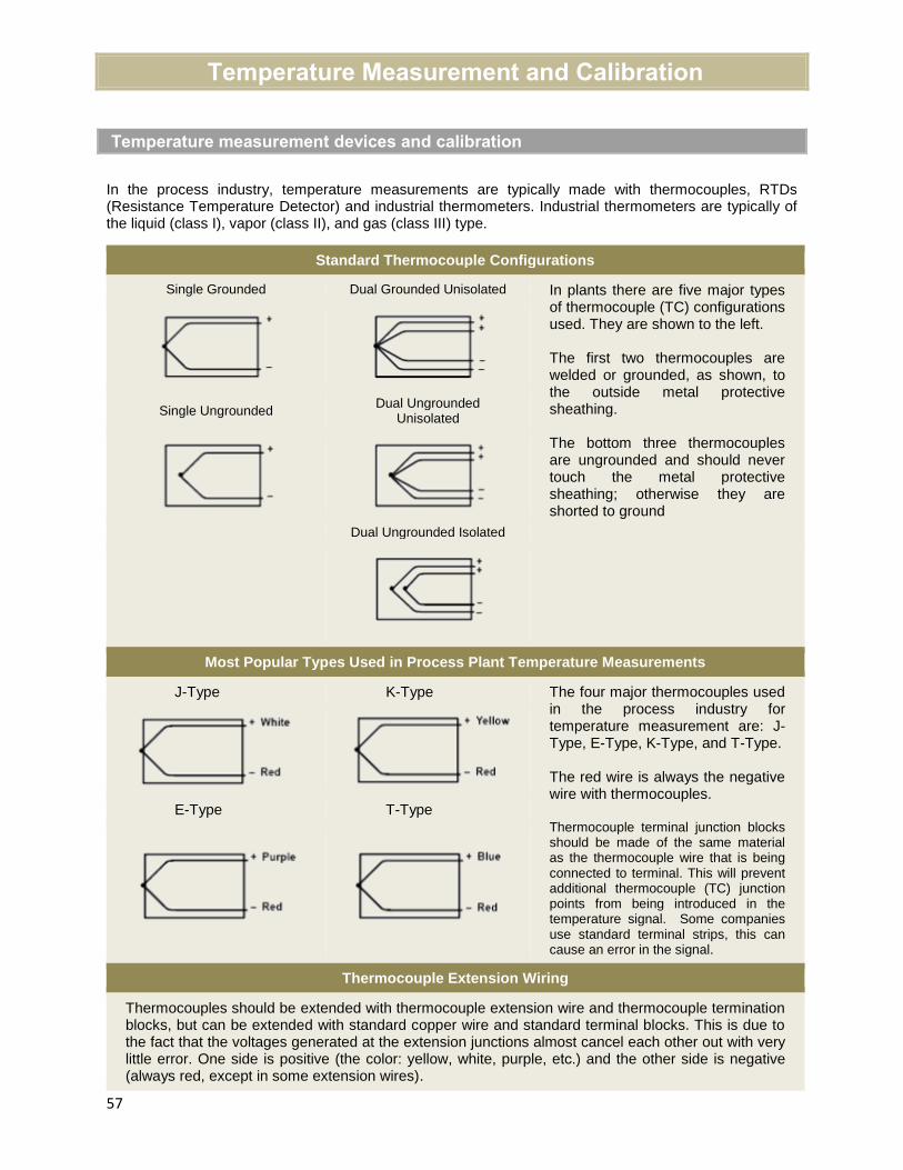
57
Temperature Measurement and Calibration
Temperature measurement devices and calibration
In the process industry, temperature measurements are typically made with thermocouples, RTDs (Resistance Temperature Detector) and industrial thermometers. Industrial thermometers are typically of the liquid (class I), vapor (class II), and gas (class III) type.
Standard Thermocouple Configurations
Single Grounded Dual Grounded Unisolated In plants there are five major types of thermocouple (TC) configurations used. They are shown to the left.
The first two thermocouples are welded or grounded, as shown, to the outside metal protective sheathing.
The bottom three thermocouples are ungrounded and should never touch the metal protective sheathing; otherwise they are shorted to ground
Single Ungrounded Dual Ungrounded
Unisolated
Dual Ungrounded Isolated
Most Popular Types Used in Process Plant Temperature Measurements
J-Type K-Type The four major thermocouples used in the process industry for temperature measurement are: J-Type, E-Type, K-Type, and T-Type.
The red wire is always the negative wire with thermocouples.
Thermocouple terminal junction blocks should be made of the same material as the thermocouple wire that is being connected to terminal. This will prevent additional thermocouple (TC) junction points from being introduced in the temperature signal. Some companies use standard terminal strips, this can cause an error in the signal.
E-Type T-Type
Thermocouple Extension Wiring
Thermocouples should be extended with thermocouple extension wire and thermocouple termination blocks, but can be extended with standard copper wire and standard terminal blocks. This is due to the fact that the voltages generated at the extension junctions almost cancel each other out with very little error. One side is positive (the color: yellow, white, purple, etc.) and the other side is negative(always red, except in some extension wires).
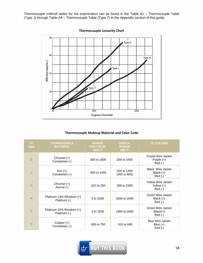
58
Thermocouple millivolt tables for the examination can be found in the Table A1 – Thermocouple Table (Type J) through Table A4 – Thermocouple Table (Type T) in the Appendix section of this guide.
Thermocouple Linearity Chart
Thermocouple Makeup Material and Color Code
TC Type
THEMOCOUPLE MATERIAL
RANGE FOR CALIB.
DEG F
USEFUL RANGE DEF F
TC COLORS
E Chromel (+)
Constantan (-) -300 to 1830 200 to 1650
Purple Wire Jacket Purple (+)
Red (-)
J Iron (+)
Constantan (-) -320 to 1400
200 to 1400 (300 to 800)
Black Wire Jacket Black (+) Red (-)
K Chromel (+) Alumel (-)
-310 to 250 200 to 2300 Yellow Wire Jacket
Yellow (+) Red (-)
R Platinum 13% Rhodium (+)
Platinum (-) 0 to 3100 1600 to 2640
Green Wire Jacket Black (+) Red (-)
S Platinum 10% Rhodium (+)
Platinum (-) 0 to 3200 1800 to 2640
Green Wire Jacket Black(+) Red (-)
T Copper (+)
Constantan (-) -300 to 750 -310 to 660
Blue Wire Jacket Blue (+) Red (-)

59
Thermocouple - worked examples (how to read the thermocouple tables)
Sample problem: What is the Millivolt (mV) output of a Type “J” thermocouple at 218°F and
referenced to a 32°F electronic ice bath?
Find the nearest temperature in Table A1 - Thermocouple Table (Type J) in the appendix of this guide.
The nearest temperature in the first column is 210. Look at the column headers at the bottom of the chart. Find the column header labeled 8. Follow the column up to the row with the 210 value. Where they meet is a total of 210°F + 8ºF = (218°F).
Read the value of mV. The answer is: 5.45 mV
Sample problem: What is the Millivolt (mV) output of a Type “K” thermocouple at 672°F from the data given? Assume the thermocouple is linear.
Given: 670°F = 14.479mV 672°F = mV 680°F = 14.713mV
We will have to interpolate the mV value for the desired temperature as follows:
Interpolation:
deg - deg
- deg - deg
desired lower valuemV mV upper value mV lower value
upper value lower value
mV lower value
Therefore the new mV for 672°F:
672 - 670
14.526 14.713 - 14.479 14.479680 - 670
The mV at 672°F is 14.526 mV
This can be verified in Table A2 –Thermocouple Table (Type K) in the appendix.
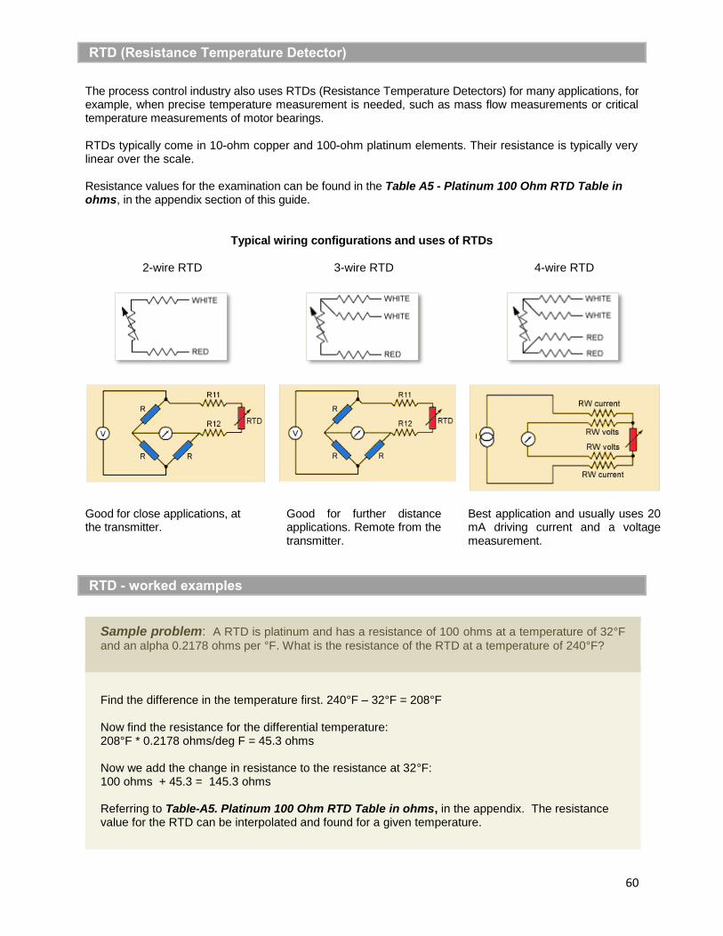
60
RTD (Resistance Temperature Detector)
The process control industry also uses RTDs (Resistance Temperature Detectors) for many applications, for example, when precise temperature measurement is needed, such as mass flow measurements or critical temperature measurements of motor bearings.
RTDs typically come in 10-ohm copper and 100-ohm platinum elements. Their resistance is typically very linear over the scale.
Resistance values for the examination can be found in the Table A5 - Platinum 100 Ohm RTD Table in ohms, in the appendix section of this guide.
Typical wiring configurations and uses of RTDs
2-wire RTD 3-wire RTD 4-wire RTD
Good for close applications, at the transmitter.
Good for further distance applications. Remote from the transmitter.
Best application and usually uses 20 mA driving current and a voltage measurement.
RTD - worked examples
Sample problem: A RTD is platinum and has a resistance of 100 ohms at a temperature of 32°F
and an alpha 0.2178 ohms per °F. What is the resistance of the RTD at a temperature of 240°F?
Find the difference in the temperature first. 240°F – 32°F = 208°F
Now find the resistance for the differential temperature: 208°F * 0.2178 ohms/deg F = 45.3 ohms
Now we add the change in resistance to the resistance at 32°F: 100 ohms + 45.3 = 145.3 ohms
Referring to Table-A5. Platinum 100 Ohm RTD Table in ohms, in the appendix. The resistance value for the RTD can be interpolated and found for a given temperature.

61
Sample problem: In the bridge circuit below, if R1 and R2 are 200 ohms and the RTD is at 60°F. What resistance should R3 measure, to balance the circuit and give the meter a reading of 0 volts? The RTD is platinum and measures 100 ohms at 32°F with an alpha of 0.2178 ohms per °F.
Find the difference in the temperature first. 60°F – 32°F = 28°F
Now find the resistance for the differential temperature:
28°F * 0.2178 ohms/°F = 6.0984 ohms
Now we add the change in resistance to the resistance at 32°F:
100 ohms + 6.0984 = 106.0984 ohms
The resistor R3 needs to be 106 ohms to balance the bridge and give 0 volts at the meter.
Sample problem: In the bridge circuit above, R1 and R2 are 200 ohms. R3 is150 ohms. The
excite voltage to the bridge is 10 volts. If the meter is reading 0.4 volts (the positive is on the right side and the negative on the left side) what is the temperature at the RTD?
Find the voltage on the left side of the bridge. This is the voltage we will add to the meter voltage on the right side. We will use the voltage divider theorem to find the voltage across R1.
11
1 2
200(10 ) (10 ) 5
200 200R
RV V V V
R R
This means the voltage across the RTD is 5.0V + 0.4V = 5.4 volts.
We will now use the voltage divider theorem to find the resistance of RTD.
3
(10 )RTDRTD
RTD R
RV V
R R
; 5.4 (10 )
150
RTD
RTD
RV V
R
Solving for RTDR :
5.4 10150
RTD
RTD
R
R
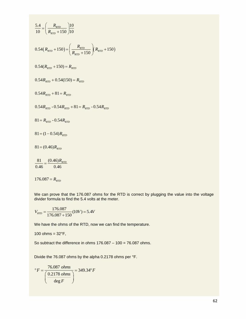
62
5.4 10
10 150 10
0.54 150 150150
0.54( 150)
0.54 0.54(150)
0.54 81
0.54 - 0.54 81 - 0.54
81 - 0.54
81 (1 0.54)
81 (0.46)
RTD
RTD
RTDRTD RTD
RTD
RTD RTD
RTD RTD
RTD RTD
RTD RTD RTD RTD
RTD RTD
RTD
R
R
RR R
R
R R
R R
R R
R R R R
R R
R
R
(0.46)81
0.46 0.46
176.087
RTD
RTD
RTD
R
R
We can prove that the 176.087 ohms for the RTD is correct by plugging the value into the voltage divider formula to find the 5.4 volts at the meter.
176.087(10 ) 5.4
176.087 150RTDV V V
We have the ohms of the RTD, now we can find the temperature. 100 ohms = 32°F,
So subtract the difference in ohms 176.087 – 100 = 76.087 ohms.
Divide the 76.087 ohms by the alpha 0.2178 ohms per °F.
76.087 349.34
0.2178
deg
ohmsF F
ohms
F

63
Add the 32°F bias for 100 ohms to the 349.34°F for 76.087 ohms and we get: 349.34°F + 32.00°F = 381.34°F.
Installing RTDs and Thermocouples into a process stream
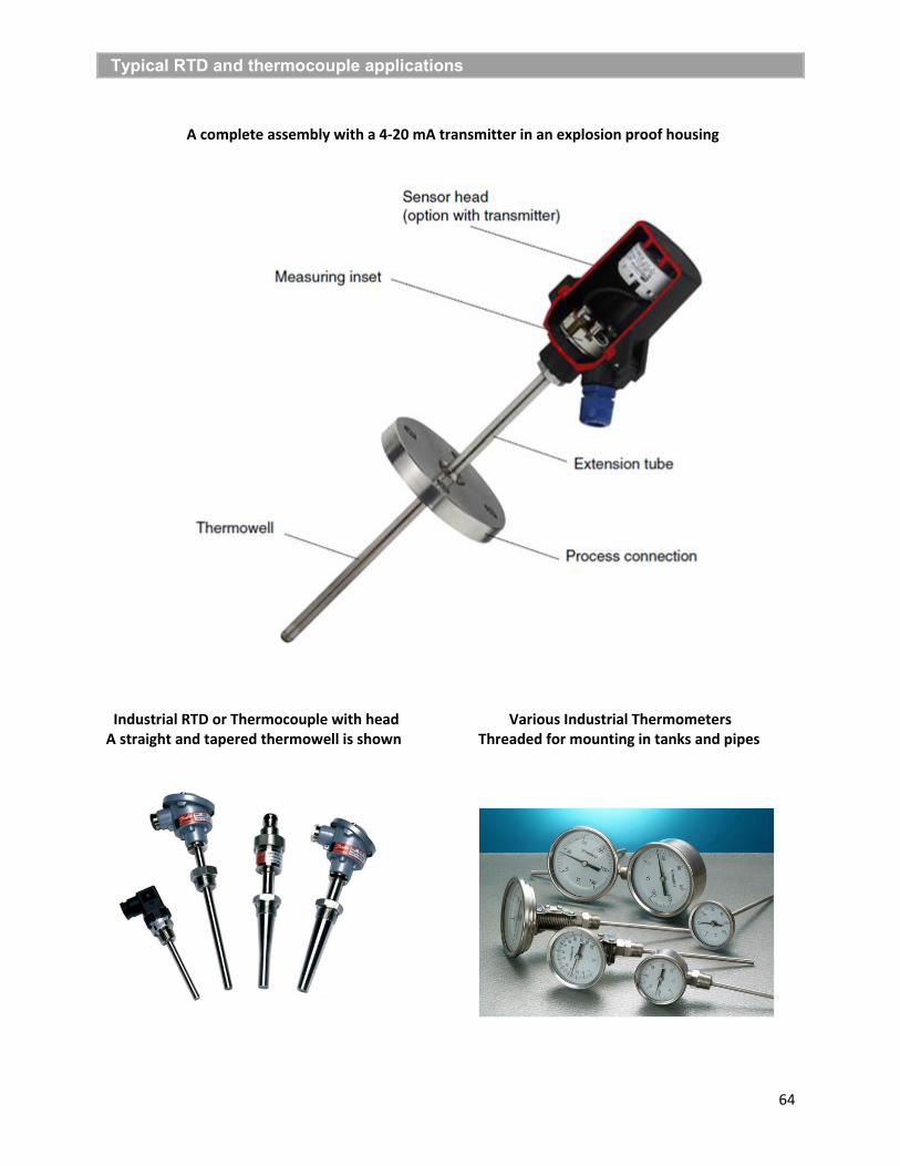
64
Typical RTD and thermocouple applications
A complete assembly with a 4-20 mA transmitter in an explosion proof housing
Industrial RTD or Thermocouple with head Various Industrial Thermometers A straight and tapered thermowell is shown Threaded for mounting in tanks and pipes

65
Pressure Measurement and Calibration
Pressure measurement and head pressure
Pressure is measured in typically two different forms. Pounds per square inch (psi) or in head pressure. Head pressure is measured in inches or feet of water column (H2O).
Head pressure is independent of the tank’s height or area. The transmitter measures head pressure. Head pressure is the measure of the potential energy in the system. The transmitter measurement is from how high is the fluid falling. The distance the fluid falls indicates the force generated (F=ma). This is why the density of the fluid must be known to calibrate a pressure transmitter for a process, to obtain the fluid mass. The calibration process uses specific gravity (s.g.), the ratio of a known density of a fluid divided by the density of water (H2O).
To illustrate these facts, we will start with one gallon of water. The gallon of water equals 231 cubic inches and weighs approximately 8.324 pounds at 60°F. Pressure is measured in PSI (pounds per square inch). Only one (1) square inch of area is needed to calculate the height of the water and the force it is excerpting. Remember force divided by area = pressure.
Stack 231 cubic inches of water on top of each other, to form a tall column of water, with a base of one (1) square inch. The column of water will be 231 inches tall. Divide the height of the column of water, 231 inches, by the weight of one (1) gallon of water, 8.324 pounds. The result will be 27.691 or 27.7 inches of water per pound of water, over a one square inch of area. Therefore 27.7 inches H2O, of head pressure, equals one (1) PSI.
By knowing the specific gravity of the fluid to be measured, multiplied by the height of the tank in inches, an equivalent value in inches of water can be found. The transmitter can now be calibrated in inches of water, regardless of the fluid. If the tank’s fluid has a s.g. equal to 0.8 and a height of 100 inches tall, then the height in inches of H2O will be:
(100” of fluid * 0.8 s.g. = 80” of H2O).
Pressure transmitters are purchased in different sizes of measurement. They are in ranges of inches H2O, psig (the “g” stands for gauge pressure) or psia (the “a” stands for absolute pressure). When the symbol psid (the “d” stands for differential pressure) is called for, a standard psig transmitter is used. Most industrial pressure transmitters are differential pressure transmitters. They act on differential forces applied to each side of the transmitter. The force is produced by the pressure in the system multiplied by the area of the
diaphragm.
66
Applying pressure measurement and signals - worked examples
Differential pressure and meter calibration
Differential pressure or differential head pressure is used to calibrate transmitters for pressure, level, flow and density measurements. The transmitter has a high side, marked with an H, and a low side, marked with a L. The low side will typically go to atmospheric pressure or to a fixed height wet leg measurement. The high side will typically go to the tank, where the varying height of fluid is to be measured. When calibrating an instrument remember: The low side is the negative scale, below zero, and the high side is the positive scale, above zero. The transmitter’s sensor element is static in position or elevation and therefore the transmitter itself is always equal to zero elevation. This will be discussed in detail in the section on Level Measurement.
Transmitters can be purchased in ranges of 25 in. of H2O, 250 in. of H2O, 1000 in. of H2O, 300 psi
and 2000 psi.
The formula for calibration is: (high side inches x s.g.) – (low side inches x s.g.) = lower or upper range value.Note: Gives LRV when empty or minimum and URV when full or maximum
Sample problem: A pressure gauge is reading 25 pisg. It is attached to a tank filled with a fluid.
The bottom of tank is 65 feet above the ground. The pressure gauge is 5 feet above the ground. The fluid has a specific gravity of (0.7 s.g.). What is the level of the fluid in the tank?
First convert the psi gauge measurement to feet of head measurement.
25 psi * 2.31 feet per psi = 57.75 feet of H2O.
Next find the elevation of the bottom of tank in relation to the elevation of the pressure gauge. Tank bottom in feet – pressure gauge elevation in feet, equals the height in feet to the bottom of tank.
65 feet– 5 feet = 60 feet of head to bottom of the tank.
Note: Head is always measured in the standard of inches or feet of water column (WC / w.c.).
Multiply the head between the bottom of the tank and the pressure gauge times the s.g. to get the head equal to H2O.
60 feet of fluid * 0.7 s.g. = 42 feet H2O to bottom of tank from the pressure gauge.
Next subtract (the height from the pressure gauge to the bottom of the tank in feet of H2O), from (the total height of fluid in feet of in H2O above the pressure gauge), to find (the height of the fluid in the tank in H2O).
(57.75 feet of H2O total head) – (42 feet of H2O below the tank) = (feet of fluid in H2O in the tank).
(57.75 feet total) – (42 feet to bottom tank from the pressure gauge) = 15.75 feet in H2O in the tank
Next convert height in feet of H2O to height of fluid with a specific gravity (s.g.) of 0.7:
15.75 feet of H2O / 0.7 s.g. = 22.5 feet of total height of the fluid column in the tank
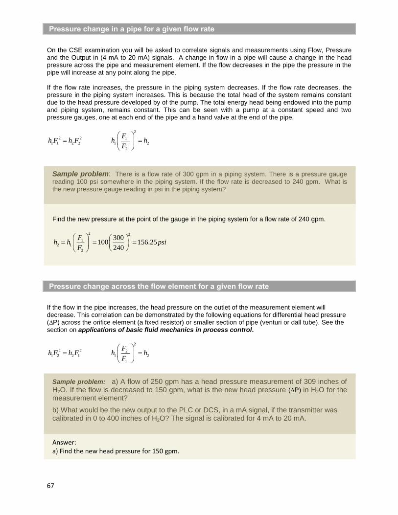
67
Pressure change in a pipe for a given flow rate
On the CSE examination you will be asked to correlate signals and measurements using Flow, Pressure and the Output in (4 mA to 20 mA) signals. A change in flow in a pipe will cause a change in the head pressure across the pipe and measurement element. If the flow decreases in the pipe the pressure in the pipe will increase at any point along the pipe.
If the flow rate increases, the pressure in the piping system decreases. If the flow rate decreases, the pressure in the piping system increases. This is because the total head of the system remains constant due to the head pressure developed by of the pump. The total energy head being endowed into the pump and piping system, remains constant. This can be seen with a pump at a constant speed and two pressure gauges, one at each end of the pipe and a hand valve at the end of the pipe.
2
2 2 11 1 2 2 1 2
2
Fh F h F h h
F
Sample problem: There is a flow rate of 300 gpm in a piping system. There is a pressure gauge reading 100 psi somewhere in the piping system. If the flow rate is decreased to 240 gpm. What is the new pressure gauge reading in psi in the piping system?
Find the new pressure at the point of the gauge in the piping system for a flow rate of 240 gpm.
2 2
12 1
2
300100 156.25
240
Fh h psi
F
Pressure change across the flow element for a given flow rate
If the flow in the pipe increases, the head pressure on the outlet of the measurement element will decrease. This correlation can be demonstrated by the following equations for differential head pressure (∆P) across the orifice element (a fixed resistor) or smaller section of pipe (venturi or dall tube). See the section on applications of basic fluid mechanics in process control.
2
2 2 21 2 2 1 1 2
1
Fh F h F h h
F
Sample problem: a) A flow of 250 gpm has a head pressure measurement of 309 inches of H2O. If the flow is decreased to 150 gpm, what is the new head pressure (∆P) in H2O for the measurement element?
b) What would be the new output to the PLC or DCS, in a mA signal, if the transmitter wascalibrated in 0 to 400 inches of H2O? The signal is calibrated for 4 mA to 20 mA.
Answer: a) Find the new head pressure for 150 gpm.

68
2 2
22 1 2
1
150; 309 111.24
250
Fh h in H O
F
b) Find the mA output:
The output signal is the square root of the ratio of change in head pressure (new measurement) to the full scale calibrated range of the transmitter. First find the % of head pressure in the scale of 0 to 400 inches H2O.
111.24% 0.2781
400head
The output is a 4 mA to 20 mA current signal. The span is 16 mA (20 mA – bias of 4 mA)
Since the flow rate is a squared function, we must first extract the square root of the % measurement to find the % of output signal.
Pressure calibration of transmitter
Sample problem: The pressure in a pipe is to be measured. The maximum pressure is measured as 462 feet of head of natural gas. It is to be displayed in units of psig. What is the calibration of the transmitter to display this pressure in 0 to 100% psig on the display? The minimum pressure measurement will be zero feet of head?
Find the psig for the given maximum head pressure: psig = feet head / 2.31 psig per foot of head
Maximum measurement in psig: 200 psig = 462 / 2.31
Next find the calibration range to order the transmitter:
The formula for calibration is: (high side psi) – (low side psi) = lower or upper range value.
Note: Gives lower range value when minimum and upper range value when maximum
LRV = 200 – 0 = 200 psi URV = 0 – 0 = 0 psi
The transmitter will be calibrated as: 0 to 200 psig
output mA = 0.2781*16 mA +4 mA bias=12.44 mA

69
Level Measurement and Calibration
Applying level measurement and calibration - Worked examples
TUNED-SYSTEM BALANCED SYSTEM WET LEG WET/DRY LEG
The calibration procedure below is as follows.
The level in a vessel or tank can be measured by a number of methods: differential pressure; displacement of volume; bubbler tube; capacitance; sonar; radar; weight, to name a few. This book will focus on differential pressure, displacement of volume, and bubbler tube for the examination.
REMEMBER: (high side inches x s.g.) – (low side inches x s.g.) = lower or upper range value.
See Example 1.
The low side of the transmitter is open to atmosphere. Atmospheric pressure is pushing on the low side. The high side of the transmitter is connected to the tank; it also has atmospheric pressure pushing on it. The atmospheric pressures on each side of the transmitter cancel out. In the example, the first line of math will be the LRV and the second line of math will be the URV. The tank has 100 inches of fluid with a s.g. of1.0. The calibrated Range of the instrument will be 0” to 100” of water or H2O. The Span of the transmitter is: (100” x 1.0 = 100”)
See Example 2.
The low side of the transmitter is open to atmosphere. Atmospheric pressure is pushing on the low side. The high side of the transmitter is connected to the tank; it also has atmospheric pressure pushing on it. The atmospheric pressures on each side of the transmitter cancel out. In the example, the first line of math will be the LRV and the second line of math will be the URV.
The tank has a 100-inch level and the tube dropping down below the tank adds 20” of fluid height, with as.g. of 1.0. The calibrated Range of the instrument will be 20” to 120” of water or H2O. Remember the
minimum measurement cannot be lower than the fixed tube height of 20”. Suppress the zero with the hard
wire jumper or set the variable in the transmitter and make 20” a live zero for the instrument. In pneumatic instruments a suppression kit must be installed.
The Span of the transmitter is: (100” x 1.0 = 100”)
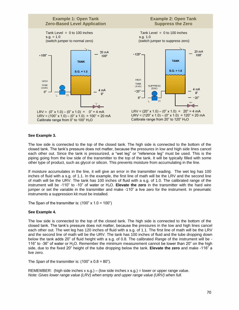
70
Example 1: Open Tank Zero-Based Level Application
Example 2: Open Tank Suppress the Zero
Tank Level = 0 to 100 inches s.g. = 1.0(switch jumper to normal zero)
LRV = (0” x 1.0) – (0” x 1.0) = 0” = 4 mA URV = (100” x 1.0) – (0” x 1.0) = 100” = 20 mA Calibrate range from 0” to 100” H2O
Tank Level = 0 to 100 inchess.g. 1.0(switch jumper to suppress zero)
LRV = (20” x 1.0) – (0” x 1.0) = 20” = 4 mA URV = (120” x 1.0) – (0” x 1.0) = 120” = 20 mA
Calibrate range from 20” to 120” H2O
See Example 3.
The low side is connected to the top of the closed tank. The high side is connected to the bottom of the closed tank. The tank’s pressure does not matter, because the pressures in low and high side lines cancel each other out. Since the tank is pressurized, a “wet leg” or “reference leg” must be used. This is thepiping going from the low side of the transmitter to the top of the tank. It will be typically filled with some other type of product, such as glycol or silicon. This prevents moisture from accumulating in the line.
If moisture accumulates in the line, it will give an error in the transmitter reading. The wet leg has 100 inches of fluid with a s.g. of 1.1. In the example, the first line of math will be the LRV and the second lineof math will be the URV. The tank has 100 inches of fluid with a s.g. of 1.0. The calibrated range of theinstrument will be -110” to -10” of water or H2O. Elevate the zero in the transmitter with the hard wire jumper or set the variable in the transmitter and make -110” a live zero for the instrument. In pneumatic instruments a suppression kit must be installed.
The Span of the transmitter is: (100” x 1.0 = 100”)
See Example 4.
The low side is connected to the top of the closed tank. The high side is connected to the bottom of the closed tank. The tank’s pressure does not matter, because the pressures in the low and high lines cancel each other out. The wet leg has 120 inches of fluid with a s.g. of 1.1. The first line of math will be the LRVand the second line of math will be the URV. The tank has 100 inches of fluid and the tube dropping down below the tank adds 20” of fluid height with a s.g. of 0.8. The calibrated Range of the instrument will be - 116” to -36” of water or H2O. Remember the minimum measurement cannot be lower than 20” on the high side, due to the fixed 20” height of the tube dropping below the tank. Elevate the zero and make -116” a live zero.
The Span of the transmitter is: (100” x 0.8 = 80”).
REMEMBER: (high side inches x s.g.) – (low side inches x s.g.) = lower or upper range value. Note: Gives lower range value (LRV) when empty and upper range value (URV) when full.
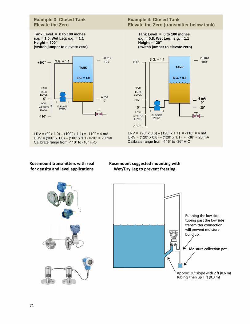
71
Example 3: Closed Tank Elevate the Zero
Example 4: Closed Tank Elevate the Zero (transmitter below tank)
Tank Level = 0 to 100 inches s.g. = 1.0, Wet Leg: s.g. = 1.1Height = 100” (switch jumper to elevate zero)
LRV = (0” x 1.0) – (100” x 1.1) = -110” = 4 mA URV = (100” x 1.0) – (100” x 1.1) =-10” = 20 mA Calibrate range from -110” to -10” H2O
Tank Level = 0 to 100 inchess.g. = 0.8, Wet Leg: s.g. = 1.1Height = 120” (switch jumper to elevate zero)
LRV = (20” x 0.8) – (120” x 1.1) = -116” = 4 mA URV = (120” x 0.8) – (120” x 1.1) = -36” = 20 mA Calibrate range from -116” to -36” H2O
Rosemount transmitters with seal Rosemount suggested mounting with for density and level applications Wet/Dry Leg to prevent freezing

72
Level displacer (Buoyancy)
The displacer tube for liquid level measurement is based on Archimedes principle that, the buoyancy force exerted on a sealed body immersed in a liquid is equal to the weight of the liquid displaced.
There are two types of displacer transmitters in common use today: torque tube and spring operated.
(8.338)
231
d f
f
Vf G
Where:
f = buoyancy force in lbf Vd f = total volume of displaced process fluid in cubic inches Ls = the submerged length of the displacer in process fluid 231 = cubic inches in one gallon of water 8.338 = weight of one gallon of water in pounds Gf = specific gravity of displaced process fluid
Sample problem: a) What is the force upward on the 30” displacer, if the displacer is 4” in diameter
and submerged 10” in a fluid, with a specific gravity of 0.72?
b) What is the mA output and percent output of the process signal?
Answer:
a) Find displaced volume:
23
1610 125.66
4 4d f s
DV L in
Find displacement force upward
125.66(8.33) (8.338)(0.72) 3.266
231 231
df
f
Vf G lbf
b) Find displacement force upward for the total 30 inches submerged :
23
1630 376.99
4 4d f s
DV L in
376.99(8.338) (8.33)(0.72) 9.798
231 231
d f
f
Vf G lbf

73
Find the % output and mA:
3.26% 0.333 100 33.3% output
9.79
0.333 16 4 9.328 outputmA mA mA
Various types of displacement measuring devices and transmitters
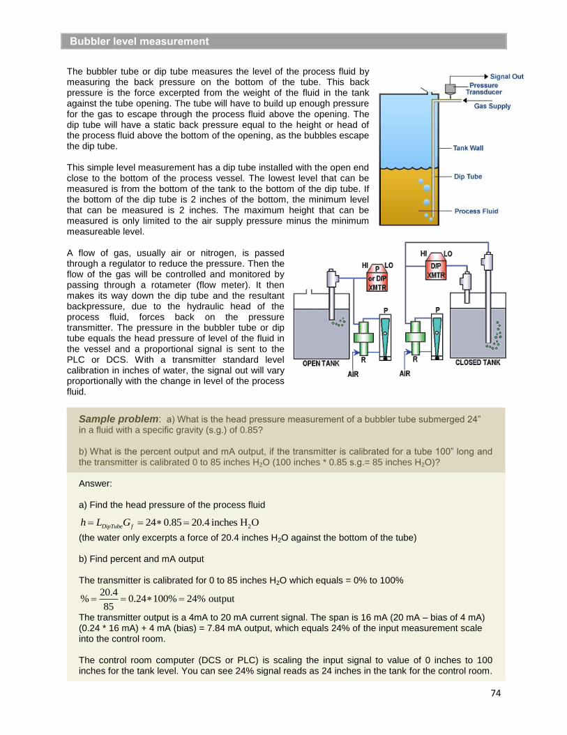
74
Bubbler level measurement
The bubbler tube or dip tube measures the level of the process fluid by measuring the back pressure on the bottom of the tube. This back pressure is the force excerpted from the weight of the fluid in the tank against the tube opening. The tube will have to build up enough pressure for the gas to escape through the process fluid above the opening. The dip tube will have a static back pressure equal to the height or head of the process fluid above the bottom of the opening, as the bubbles escape the dip tube.
This simple level measurement has a dip tube installed with the open end close to the bottom of the process vessel. The lowest level that can be measured is from the bottom of the tank to the bottom of the dip tube. If the bottom of the dip tube is 2 inches of the bottom, the minimum level that can be measured is 2 inches. The maximum height that can be measured is only limited to the air supply pressure minus the minimum measureable level.
A flow of gas, usually air or nitrogen, is passed through a regulator to reduce the pressure. Then the flow of the gas will be controlled and monitored by passing through a rotameter (flow meter). It then makes its way down the dip tube and the resultant backpressure, due to the hydraulic head of the process fluid, forces back on the pressure transmitter. The pressure in the bubbler tube or dip tube equals the head pressure of level of the fluid in the vessel and a proportional signal is sent to the PLC or DCS. With a transmitter standard level calibration in inches of water, the signal out will vary proportionally with the change in level of the process fluid.
Sample problem: a) What is the head pressure measurement of a bubbler tube submerged 24” in a fluid with a specific gravity (s.g.) of 0.85?
b) What is the percent output and mA output, if the transmitter is calibrated for a tube 100” long andthe transmitter is calibrated 0 to 85 inches H2O (100 inches * 0.85 s.g.= 85 inches H2O)?
Answer:
a) Find the head pressure of the process fluid
224 0.85 20.4 inches H ODipTube fh L G
(the water only excerpts a force of 20.4 inches H2O against the bottom of the tube)
b) Find percent and mA output
The transmitter is calibrated for 0 to 85 inches H2O which equals = 0% to 100%
20.4% 0.24 100% 24% output
85
The transmitter output is a 4mA to 20 mA current signal. The span is 16 mA (20 mA – bias of 4 mA) (0.24 * 16 mA) + 4 mA (bias) = 7.84 mA output, which equals 24% of the input measurement scale into the control room.
The control room computer (DCS or PLC) is scaling the input signal to value of 0 inches to 100 inches for the tank level. You can see 24% signal reads as 24 inches in the tank for the control room.

75
Density measurement
Head pressure and volume displacement can be used to measure density. By using a differential head pressure transmitter, calibrated in inches of water, connect the high and low lines to the tank at a fixed distance of separation, such as 10”. Both taps of the density transmitter must be completely submerged below the top of fluid whose density is being measured. The height measured in inches of water divided by 10” (in our example), is the (s.g.) of the unknown fluid. Example: The density transmitter is measuring 7 inches H2O, the s.g. = 0.7 (7”/10” = 0.7). See figure 2 below.
With the specific gravity (s.g.) known from the density transmitter, and a second level transmittercalibrated in inches of H2O, the tank level can be found. The level measurement can be divided by the (s.g.) measurement from the density transmitter, to show the true height of the process fluid in the tank.
Sample problem: Find the density of the hydrocarbon product and the interface level of the water in the bottom of the tank in figure 2. The wet leg (sealed diaphragm leg) has a s.g. equal to 1.1
Remember: [(high side * s.g.) – (low side * s.g.)] = LRV or URV
Density: LRV = (0” * 1.0) – (10” * 1.1) = -11” H2O (transmitter not covered with fluid or tank empty) URV = (10” * s.g.) – (10” * 1.1) = ?” H2O (transmitter completely covered with process fluid)
URV = (10” * 0.825) – (10” * 1.1) = -2.75” H2O (for Crude oil 40o API)
Find s.g. for crude oil 40o API: [(-11) – (-2.75)] = 8.25” so… 8.25”/10” = 0.825 s.g.
URV = (10” * 0.7874) – (10” * 1.1) = -3.126” H2O (for ethyl alcohol) Find s.g. for ethyl alcohol: [(-11) – (-3.126)] = 7.874” so… 7.874”/10” = 0.7874 s.g.s.g. process signal = mA = [16 * 0.7874] + 4 = 16.5984mA or 78.74% signal.
Level: (% Level signal / % Density signal) * Tank Level = level of process fluid in the tank.
Note: The tank level measurement can be any height and the fluid to be measured of any density. Remember to elevate the zero on the density transmitter.
Figure 1 Figure 2
Using a bubbler arrangement to measure level with a varying density of process fluid: Connect the high and low lines to the dip tubes as shown above in figure 1, at a fixed distance of separation in height, such as 2” or 10”. We will use a 2” height differential between the bottoms of the tubes. The maximum distance above L1 equals 20” of process fluid.
Sample problem: Find the density and level in the tank in figure 1, using a bubbler arrangement.
Density is calculated as LRV = (0” * s.g.) – (0” * s.g.) = 0” H2O (Density minimum, tank empty) URV = (0” * s.g.) – (2” * 1.0) = -2” H2O (Density equals H2O, L2 submersed and fluid at bottom of L1)

76
Remember to elevate the zero in the transmitter!
Since any level above L1 will cancel out in the density transmitter, the output is simply the percent signal which equals the s.g. of the process fluid.Example: -2” * 0.7874 = -1.5748” H2O (for ethyl alcohol) -1.5748”/-2” = s.g. = 0.7874 or 78.74%signal.
Level is calculated as: For a 15” level of ethyl alcohol above L1:
% mA = (15” * s.g.) = 11.811” H2O = (11.811” level)/( 20” max level) = 0.59055 or 59.055% signal At DCS/PLC the display will show Level/Density = 59.055/78.74 = 0.75 or 75% level.
Level = 0.75 * 20” = 15” level
Interface level measurement
The combined level of the fluids in the tank must be above the top tap of the level transmitter connected to the tank. The distance “h” is the height between the high and low side taps and must be at a known constant distance. We want the lower tap (high side) to see the difference in height in the higher specific gravity fluid in the bottom of the tank, minus the lower specific gravity fluid in the top of the tank. Say we are trying to measure the level of water in a tank holding a hydrocarbon product.
If we know the s.g. of the hydrocarbon, we can calibrate the transmitter to an output of zero % signal, due to cancellation of forces (pressure * area) on both sides. Then when the heavier water product enters the tank we can measure this extra weight by the force it is excerpting on the transmitter in inches of water for an interface height. If we do not know the density of the hydrocarbon product, we will do what we did in the previous examples for finding the density of a fluid in a tank. We will put the density transmitter on the upper fluid level and then divide the bottom level measurement by the density multiplier.
If the wet leg and the lighter hydrocarbon product in the tank are the same fluid, the two levels (or forces) will cancel each other out when there is no water in the tank. (The s.g. of thehydrocarbon product must be known and consistent, otherwise a density transmitter should be used to perform the level calculation for accuracy).
The height in H2O in the tank = [(height of H2O) + (height of the lighter fluid * s.g.)]
The height in H2O in the wet leg = (height of the lighter fluid in the wet leg * s.g.)
The signal height in inches of H2O from the transmitter = [(height of H2O) + (height of the lighter fluid * s.g.)] - (height of wet leg * s.g.) = measurement inchesH2O
Sample problem: Find the interface level in the tank.
The distance between taps is h = 100 inches Hydrocarbon s.g. = 0.7 (can be found from the density transmitter) Water (H2O) s.g. = 1.0 Maximum interface level to be measured = 50 inches (50% full)
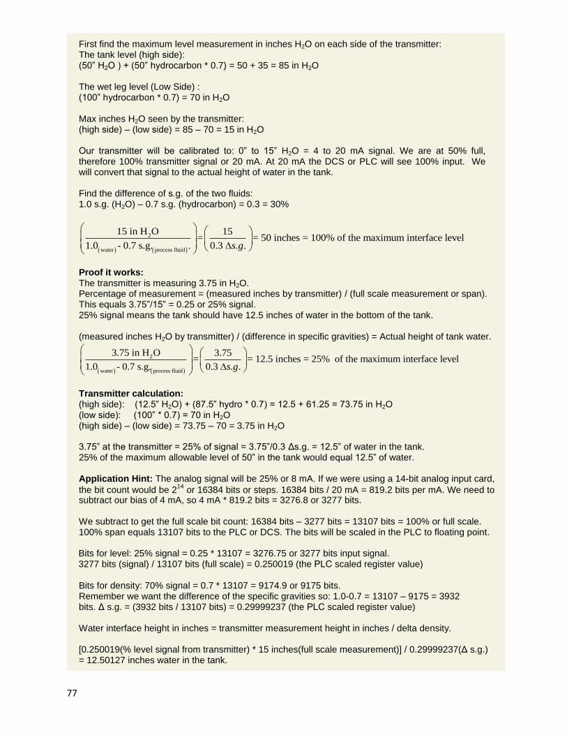
77
First find the maximum level measurement in inches H2O on each side of the transmitter: The tank level (high side):(50” H2O ) + (50” hydrocarbon * 0.7) = 50 + 35 = 85 in H2O
The wet leg level (Low Side) : (100” hydrocarbon * 0.7) = 70 in H2O
Max inches H2O seen by the transmitter: (high side) – (low side) = 85 – 70 = 15 in H2O
Our transmitter will be calibrated to: 0” to 15” H2O = 4 to 20 mA signal. We are at 50% full, therefore 100% transmitter signal or 20 mA. At 20 mA the DCS or PLC will see 100% input. We will convert that signal to the actual height of water in the tank.
Find the difference of s.g. of the two fluids:1.0 s.g. (H2O) – 0.7 s.g. (hydrocarbon) = 0.3 = 30%
2
water process fluid
15 in H O 15= = 50 inches = 100% of the maximum interface level
1.0 - 0.7 s.g. . 0.3 . .s g
Proof it works: The transmitter is measuring 3.75 in H2O. Percentage of measurement = (measured inches by transmitter) / (full scale measurement or span). This equals 3.75”/15” = 0.25 or 25% signal. 25% signal means the tank should have 12.5 inches of water in the bottom of the tank.
(measured inches H2O by transmitter) / (difference in specific gravities) = Actual height of tank water.
2
water process fluid
3.75 in H O 3.75= = 12.5 inches = 25% of the maximum interface level
1.0 - 0.7 s.g. 0.3 . .s g
Transmitter calculation: (high side): (12.5” H2O) + (87.5” hydro * 0.7) = 12.5 + 61.25 = 73.75 in H2O(low side): (100” * 0.7) = 70 in H2O (high side) – (low side) = 73.75 – 70 = 3.75 in H2O
3.75” at the transmitter = 25% of signal = 3.75”/0.3 Δs.g. = 12.5” of water in the tank. 25% of the maximum allowable level of 50” in the tank would equal 12.5” of water.
Application Hint: The analog signal will be 25% or 8 mA. If we were using a 14-bit analog input card,
the bit count would be 214
or 16384 bits or steps. 16384 bits / 20 mA = 819.2 bits per mA. We need to subtract our bias of 4 mA, so 4 mA * 819.2 bits = 3276.8 or 3277 bits.
We subtract to get the full scale bit count: 16384 bits – 3277 bits = 13107 bits = 100% or full scale. 100% span equals 13107 bits to the PLC or DCS. The bits will be scaled in the PLC to floating point.
Bits for level: 25% signal = 0.25 * 13107 = 3276.75 or 3277 bits input signal. 3277 bits (signal) / 13107 bits (full scale) = 0.250019 (the PLC scaled register value)
Bits for density: 70% signal = 0.7 * 13107 = 9174.9 or 9175 bits. Remember we want the difference of the specific gravities so: 1.0-0.7 = 13107 – 9175 = 3932 bits. Δ s.g. = (3932 bits / 13107 bits) = 0.29999237 (the PLC scaled register value)
Water interface height in inches = transmitter measurement height in inches / delta density.
[0.250019(% level signal from transmitter) * 15 inches(full scale measurement)] / 0.29999237(Δ s.g.) = 12.50127 inches water in the tank.

78
Radar and Ultrasonic level measurement
Time of flight technology
Time of flight devices are much newer technology than hydrostatic devices and consist of ultrasonic and
radar devices (non-contact and guided wave). Radar is an acronym for Radio Detection and Ranging. Radar devices used for level measurement operate with electromagnetic radiation at wavelengths of 1.5 to 26 gigahertz. They are commonly known as microwaves. Non-contact radar and guide wave radar operate using the same principle.
Ultrasonic level measurement
Ultrasonic waves are not electromagnetic waves; they are mechanical sound waves. The speed at whichmechanical waves travel is well known, about 1096 feet per second (334 meters/second) through air at 68°F. The level of the media can be determined by measuring the amount of time it takes for the ultrasonic wave to travel to the liquid, reflect and travel back to the device.
Most ultrasonic transmitters and receivers operate from 10 KHz to 70 KHz, well above the frequency of audible sound waves. In order for ultrasonic waves to be reflected, they need a media with a certain mass (density). In level measuring applications, there must be enough mass in the media (density) to reflect the sound waves.
Equations: L = E – D and D = C x T/2L = media level E = distance from measuring device to zero level D = distance from measuring device to media C = speed of sound or speed of light T = amount of time for sound or light to travel from device to liquid and back
Based on the figure to the right the level of media can be determined from the time it takes for sound waves or electromagnetic waves to travel from the measuring device to the media and back to the measuring device.
Advantages Disadvantages Accuracy independent of density changes, dielectric or conductivity No calibration with medium required Some come with SIL 2 and 3 ratings
Minimum density required Foam is an issue False measurements with turbulent surfaces No vacuum (10 psia), no high pressures (44 psia)
Radar (non-contact)
Non-contact radar devices use microwaves in the 6 to 26 gigahertz range to measure liquid level in tanks. Like the speed of sound, the speed of light (electromagnetic radiation) is well known, 186,000 miles per second. Based on equations 1 and 2 above, the level can be calculated by knowing the dimensions of the tank and measuring the amount of time it takes for the microwaves to reflect off the process media.
Why do radar level devices use microwaves compared to other types of energy in the electromagnetic spectrum? Microwaves have little effect from type of gases, temperature, pressure, buildup and condensate. However, the ability for the process medium to reflect or not reflect microwaves needs to be taken into account. You can determine this ability to reflect light or microwaves by looking at the dielectric number of the media.

79
The dielectric number is a measure of the polarization power of an insulating material or how much charge can be stored in a type of material vs. air. Water has a dielectric number of 80 and is considered a great reflector of microwaves. Air has a dielectric number of 1 and is considered a poor reflector of microwaves. Aqueous mixtures tend to work well with radar due to the high dielectric number.
However, while hydrocarbon based liquids can be measured, the measuring ranges may be lower due to lower dielectrics numbers. Petroleum oil has a dielectric number of 2 while gasoline has a dielectric number between 2 and 3. Because, ambient conditions have little effect on microwaves, radar devices are generally accepted as the most accurate level devices – some can measure level to ±0.5 mm or ±0.02 inches. This is one of the main reasons why suppliers, processors, and sellers of crude oil and other high-cost materials will use a radar device as part of their tank gauging equipment to accurately measure level.
Guided Wave Radar (GWR)
Guided wave radar devices use the same principle as non-contact radar devices – it has the ability to transmit and receive reflected microwave energy. Guided wave (sometimes called TDR – Time Domain Reflectometry) operates at 1.5 GHz. While the electronics are mostly the same as non-contact radar, the big difference is the wave guide. The wave guide is a metal rod or rope which guides the energy to the process media. See the image to the left. The wave guide directs approximately 80% of the available energy down the guide within an 8” radius.
GWR is suitable for a variety of level measurement applications including: Unstable Process Conditions - Changes in viscosity, density, or acidity do not affect accuracy Agitated Surfaces
- Boiling surfaces, dust, foam, vapor do not effect device performance - Recirculating fluids, propeller mixers, aeration tanks Extreme Operating limits
- GWR performs well under extreme temperatures up to 600ºF (315ºC) - Capable of withstanding pressures up to 580 PSIG (40 Bar)
Fine Powders and Sticky Fluids - Paint, latex, animal fat and soy bean oil - Saw dust, carbon black, titanium tetrachloride, salt, grain - Oils or grease in tanks
Capacitance level measurement
Commercial capacitance level transmitters are proven devices and were first introduced in the 1950’s. They are also extremely versatile in that they can measure the continuous level and point level (a predetermined measurement point) of liquids, slurries, liquid-liquid interface as well as point level of solids. Capacitance technology for level devices has also become known as reactance, admittance or RF technology.
The capacitance calculation for empty and full is important because a minimum change of capacitance of about 10 pF is needed for measurement. Last but not least, foam can be tricky with capacitance probes. If the foam is conductive, the capacitance probe will see the liquid and the foam as the complete level. Capacitance transmitters and switches can come with SIL 2 and 3 ratings.
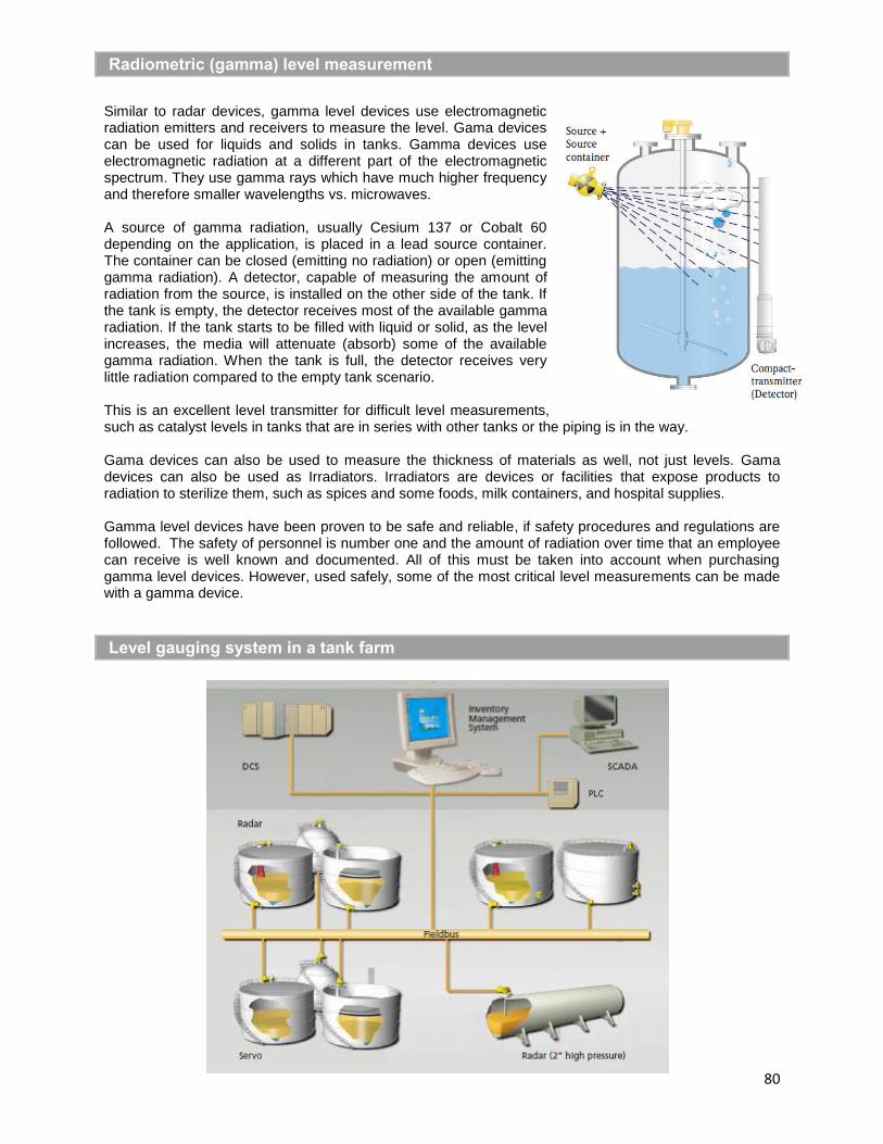
80
Radiometric (gamma) level measurement
Similar to radar devices, gamma level devices use electromagnetic radiation emitters and receivers to measure the level. Gama devices can be used for liquids and solids in tanks. Gamma devices use electromagnetic radiation at a different part of the electromagnetic spectrum. They use gamma rays which have much higher frequency and therefore smaller wavelengths vs. microwaves.
A source of gamma radiation, usually Cesium 137 or Cobalt 60 depending on the application, is placed in a lead source container. The container can be closed (emitting no radiation) or open (emitting gamma radiation). A detector, capable of measuring the amount of radiation from the source, is installed on the other side of the tank. If the tank is empty, the detector receives most of the available gamma radiation. If the tank starts to be filled with liquid or solid, as the level increases, the media will attenuate (absorb) some of the available gamma radiation. When the tank is full, the detector receives very little radiation compared to the empty tank scenario.
This is an excellent level transmitter for difficult level measurements,such as catalyst levels in tanks that are in series with other tanks or the piping is in the way.
Gama devices can also be used to measure the thickness of materials as well, not just levels. Gama devices can also be used as Irradiators. Irradiators are devices or facilities that expose products to radiation to sterilize them, such as spices and some foods, milk containers, and hospital supplies.
Gamma level devices have been proven to be safe and reliable, if safety procedures and regulations are followed. The safety of personnel is number one and the amount of radiation over time that an employee can receive is well known and documented. All of this must be taken into account when purchasing gamma level devices. However, used safely, some of the most critical level measurements can be made with a gamma device.
Level gauging system in a tank farm

81
Calculating the volume in tanks
With a head pressure measurement, the height of the liquid in a tank can be measured. This is simple with standard cylindrical tanks, but much more difficult with irregular shaped tanks.
Calculating the volume in tanks will probably not be on the CSE exam, but the formulas to calculate the volume in these tanks is derived from calculus and included in the appendix of this guide. It will show how to calculate the volume of spherical tanks and bullet tanks, so the volume can be calculated in the PLC or DCS. See the section Calculating the Volume in Tanks for the volume formulas.
The tank ends can be flat (so the tank is just a horizontal cylinder). Tanks can come with different heads (end caps). They can be dished (ASME F&D, or Flanged & Dished), 2:1 elliptical or hemispherical.
TANK VOLUME CALCULATION
Horizontal Cylinder 2
0.5-1 2
D-h
D D2cos - -h Dh-h LD2 2
2
HEAD VOLUME CALCULATION
ASME F&D 20.215483h 1.5D-h
Elliptical Head 2h 1.5D-h6
Hemispherical Head 2h 1.5D-h3
The liquid volumes in a horizontal cylinder, and ASME F&D, 2:1 elliptical and hemispherical heads are
given by these equations. The (cos-1
) or (arccos) or (arcos) function must return radians, NOT degrees. In the appendix, the volume for the tank section plus both heads combine into one formula. These formulas can be modified using the formulas above for more accuracy with different heads (end caps).
The total volume of liquid in the tank is simply the liquid volume in the cylinder plus 2 times the liquid volume in the heads. (Hint: multiply tank diameter “D” x % level signal to get “h” (the height shown on the HMI or display), and then calculate the total tank volume with the math formula in the appendix. .