Table of Contents - AVocation Systems
52
Transcript of Table of Contents - AVocation Systems


Integrating Electronic Equipment and Power into Rack Enclosures © 2002-2008 Middle Atlantic Products, Inc.
Table of Contents
Preface.............................................................................................................................................................................................................................................................................. 1 Important Things To Remember When Installing Audio / Video Equipment ...................................................................................................................................................................... 2 Dealing With Electrical Inspectors and Electrical Contractors ........................................................................................................................................................................................... 3 North American Product Safety Certification ..................................................................................................................................................................................................................... 4 Typical 120-Volt Receptacles Used For Electronic Equipment.......................................................................................................................................................................................... 5 Common Receptacle Wiring Errors ................................................................................................................................................................................................................................... 6 Calculating System Load................................................................................................................................................................................................................................................... 7 Calculating Amplifier Circuit Requirements ....................................................................................................................................................................................................................... 8 Single Circuit Sequencer Systems .................................................................................................................................................................................................................................... 9 Sequencer Systems (Multiple Modules) .......................................................................................................................................................................................................................... 10 Surge Suppression.......................................................................................................................................................................................................................................................... 11 Simplified Grounding Guidelines for Audio, Video and Electronic Systems .................................................................................................................................................................... 13 Isolated (Technical) Ground vs. Safety & Building Ground.............................................................................................................................................................................................. 14 Isolated (Technical) Ground vs. Safety & Building Ground (cont.) .................................................................................................................................................................................. 15 Isolated Ground Receptacles .......................................................................................................................................................................................................................................... 16 Wiring Isolated Ground Outlets and Conventional Outlets when using a Sub Panel....................................................................................................................................................... 17 Wiring Methods for Separately Derived Systems (Isolation Transformers) ..................................................................................................................................................................... 18 K-Rated Power Transformers.......................................................................................................................................................................................................................................... 19 The Specifics of Transformer Action on Transients......................................................................................................................................................................................................... 20 Electrostatic (Faraday) Shielding in Power Transformers................................................................................................................................................................................................ 21 Typical Three Phase Services......................................................................................................................................................................................................................................... 22 Phasing of Supply Conductors ........................................................................................................................................................................................................................................ 23 Symmetrical (Balanced) Power Systems......................................................................................................................................................................................................................... 24 Ground Myths.................................................................................................................................................................................................................................................................. 26 Grounding Gone Bad ...................................................................................................................................................................................................................................................... 27 Isolated Ground Power Strip in a Non–Isolated Rack ..................................................................................................................................................................................................... 28 Isolated Rack with Standard (not isolated) Power Strip................................................................................................................................................................................................... 30 Flexible Connections to Isolated Equipment Racks......................................................................................................................................................................................................... 31 AC Wiring Types ............................................................................................................................................................................................................................................................. 33 AC Magnetic Field Strengths from Different Wiring Types & Plug-In Power Supplies (Wall-Warts) ................................................................................................................................ 34 AC Magnetic Fields & Their Effect on Signal Wiring: Diagnosing Hum and Buzz .......................................................................................................................................................... 35 Electric Fields & Their Effect on Signal Wiring ................................................................................................................................................................................................................ 36 Signal Wiring: Unbalanced & Balanced Interfaces .......................................................................................................................................................................................................... 37 Signal Wiring: Unbalanced & Balanced Interfaces (cont.) ............................................................................................................................................................................................... 38 Single-Point Technical (Star) Ground vs. Daisy-Chain Grounding of Racks ................................................................................................................................................................... 39 Enhanced EMC Rack Bonding ........................................................................................................................................................................................................................................ 40 Introduction to Star Grounding, Signal Reference Grids & Mesh Grounding................................................................................................................................................................... 41 Star/Isolated Grounding................................................................................................................................................................................................................................................... 41 Signal Reference Grids ................................................................................................................................................................................................................................................... 42 Mesh Grounding.............................................................................................................................................................................................................................................................. 42 Authors ............................................................................................................................................................................................................................................................................ 43 References ...................................................................................................................................................................................................................................................................... 43 Notes............................................................................................................................................................................................................................................................................... 46

1
Integrating Electronic Equipment and Power into Rack Enclosures © 2002-2008 Middle Atlantic Products, Inc.
Preface
In providing this information, the intent is not to make audio/video equipment installers into electricians. Installers, however, do need a basic understanding of properly installed power distribution to avoid potential noise and safety problems during installation. In order to get a good understanding of how some potential power and grounding problems present themselves, basic knowledge of power distribution is required. It is the intent of this document to provide this information. Every state, city and municipality in the United States is responsible for its own safety standard for electrical installations. While some choose not to adopt any standard, most adopt and enact the widely-accepted National Electrical Code (NEC) or a version of the NEC enhanced to reflect the needs of their respective jurisdictions. Each is at liberty to incorporate additional requirements or remove exceptions, as they see fit. The state of New Jersey, for example, replaced the term “authority having jurisdiction (AHJ)” with “electrical subcode official” before enacting the NEC standard. Always be sure to check the requirements of the local authority having jurisdiction. The information presented in this paper is based on the NEC as it is written. Some areas may have more rigid requirements; however, the NEC is generally the minimum requirement. The NEC is updated every three years. This document is based on the 2008 version. The NEC is not intended to be used as a design specification or an instruction manual for untrained persons. In fact, some experienced installers have problems adapting the NEC to specific installations. Much of the problem is due to the many exceptions to the rules. The fact is there are more exceptions than there are rules. In addition many rules refer to, and are superseded by, several other sections of the NEC. This document should help to clarify the intentions of the NEC.

2
Integrating Electronic Equipment and Power into Rack Enclosures © 2002-2008 Middle Atlantic Products, Inc.
Important Things To Remember When Installing Audio / Video Equipment
1) Safety Comes First: The NEC Code must be adhered to at all times. 2) Bypassing or lifting equipment safety grounds may reduce hums and buzzes; but this is dangerous, violates the NEC and should
never be done!
3) Ground loops are an entirely normal occurrence. Their severity depends on many factors. They may cause significant noise problems when safety grounds of interconnected equipment in enclosures are not connected at a common point.
4) Untwisted signal conductors inside the equipment rack should not be installed in parallel (within 2”) of untwisted power
conductors or speaker wires. A hum may be induced from these wires into the signal conductors. This is especially likely in long parallel wire runs, where more separation may be required.
5) When it is necessary to install untwisted signal conductors, and untwisted power conductors or speaker wires in close proximity
to each other, coupling is minimized when the cables cross at 90-degree angles.
6) Some equipment is designed to pass noise onto the ground circuit. This noise may manifest itself as a hum or buzz in the signal path.
7) There are many causes of signal path noise. Two common problems are equipment that does not comply with either the AES48
standard (“pin one problem”), and shield current induced noise (SCIN) in signal cables. Both are beyond the scope of this paper and are well documented elsewhere (please see references listed at the end of this paper – page 42).
8) Equipment racks should be bonded per the NEC or local authority having jurisdiction. Best practices dictate that equipment
racks must be bonded together. It is best to purchase racks with pre-installed ground studs for convenience and to ensure good conductivity.
3
Integrating Electronic Equipment and Power into Rack Enclosures © 2002-2008 Middle Atlantic Products, Inc.
Dealing With Electrical Inspectors and Electrical Contractors
“Inspectors are like fuses… They only blow if there’s a problem. And like fuses, they are there for your protection; they’re not just an inconvenience.” - Jim Herrick, 2002 Most electricians and inspectors (who are usually very experienced electricians) don’t know much about audio, video or communications installation. What they usually do know very well is electrical safety and power distribution, as far as wiring and associated wiring methods are concerned. For the most part, they are only concerned with safety. Incorrectly installing a technical ground system may be safe, but may create multiple ground paths, which could contribute to system noise problems. In most areas of the country an electrical contractor’s license is required to do any type of electrical work (sometimes even low voltage). An electrical permit, issued by the municipality, is almost always required. If you are caught doing work without a permit you could pay more in fines than what you might earn on the job. If you’re not a licensed electrical contractor, it’s a good idea to develop a working relationship with one. Inspectors Will Look For:
1) Permits and licenses (State and local law). 2) Wiring installed in a neat and workmanlike manner.
-NEC: 110.12/640.6/720.11/725.24/760.24/800.24/820.24/830.24. 3) Wiring methods that are consistent with the area you’re working in. Places of Assembly, such as churches, schools and
auditoriums require different wiring methods than residential installations. 4) UL Listed equipment. –NEC: 110(Labeled)/110.2 5) Honest answers and somebody there to give them, during the inspection (Don’t leave a person with limited knowledge at the job
site to wait for the inspector!) You’ll Need To:
1) Know where the circuit breakers are that feed the equipment, and be sure the breakers are marked. –NEC: 110.22 2) Know the electrical load of your equipment and be sure wiring is of adequate size. –NEC: 220/210.19 3) Ensure low voltage wiring is not installed in the same raceway or conduit, or in close proximity to the power wiring - NEC
725.136 (unless exempted by this article) 4) Know your local codes that may supersede the NEC, which is often the case in large cities.
If your equipment is installed properly, and looks like it, you most likely will not have any problems with the inspector.
“Arguing with an inspector is like wrestling with a pig in the mud… After a while you realize the pig likes it.” (Author Unknown)

4
Integrating Electronic Equipment and Power into Rack Enclosures © 2002-2008 Middle Atlantic Products, Inc.
North American Product Safety Certification
Underwriters Laboratories, Inc. (UL) is an independent, impartial and nonprofit organization that has devoted itself to testing for public safety. To meet this objective, UL acts as a third party, evaluating thousands of different types of products, components, materials and systems.
Described here are three UL classification types: Listed, Classified and Recognized. UL specifically forbids the use of the following terms:
“UL Approved”, “UL Pending” or “Made With UL Recognized Components”
Be skeptical of equipment that is marked in such a way. UL is the most well known nationally recognized testing laboratory (NRTL). There are many others however, including ETL and the Occupational Safety and Health Administration (OSHA). Further information on OSHA can be found on its website at http://www.osha.gov
ULR
LISTED
UL Listed: This symbol represents a product that UL has tested representative samples of, and has determined that they meet UL requirements for that specific product type in the United States only.
ULRC US
LISTED
This symbol represents a product that has passed UL listing tests in both the United States and Canada. UL Inspectors also visit the factories where the UL listed products are manufactured on a regular basis to ensure products are manufactured according to UL safety standards.
This is the logo for Canada only.
UL Classified: This category of products is tested to meet specific uses or restrictions for their use, such as, “Explosion Proof” or “For Marine Use”.
R
UL Recognized: This category is for components ONLY. Generally UL listed products are manufactured using all “Recognized” components; however, this does not mean that the product is “UL Listed”. Although all recognized parts are used, the end product must still meet UL requirements to be UL listed.

5
Integrating Electronic Equipment and Power into Rack Enclosures © 2002-2008 Middle Atlantic Products, Inc.
Typical 120-Volt Receptacles Used For Electronic Equipment Receptacles have specific prong configurations indicating the voltage and amperage of the circuit for which they are designed. These receptacles and the corresponding circuit must match the plug that is attached to your equipment. Isolated ground receptacles are identified by a triangle engraved on the face and are available in all standard colors; however orange is the most typical. The triangle is not to be confused with an engraved green circle, which indicates a hospital grade device. Both symbols may appear on the same outlet. Hospital grade receptacles must pass additional UL testing, per UL Standard 498, including:
- Abrupt Plug Removal Test - Ground Contact Overstress Test - Impact Test - Assembly Security Test
Do not modify the plug on your equipment to match a receptacle that is not intended to work with your equipment. (NEC-406.7)
identified by a triangle
engraved on the face
identified by an engraved green circle on the face
NEMA 5-15R 15 amp circuit
Accepts NEMA 5-15P plug
NEMA 5-20R 20 amp circuit
Accepts NEMA 5-15P, or NEMA 5-20P plug
NEMA L5-15R 15 amp circuit Accepts NEMA
L5-15P plug
NEMA L5-20R 20 amp circuit Accepts NEMA
L5-20P plug
NEMA L5-30R 30 amp circuit Accepts NEMA
L5-30P plug
NEMA 5-20R Isolated ground
NEMA 5-20R Hospital grade

6
Integrating Electronic Equipment and Power into Rack Enclosures © 2002-2008 Middle Atlantic Products, Inc.
Common Receptacle Wiring Errors These wiring errors may not be detected by simply plugging in your equipment; it will seem to work ok, but it may cause electrical noise and may be hazardous. Always test the outlets by using a meter. If the neutral and hot conductors are reversed, it can be detected by using a voltmeter. Between neutral and ground the meter should never display more than a few volts. Between hot and ground the meter should display 120 volts (nominal). If neutral and ground conductors are reversed, it can be detected by using a clamp-on amp meter installed on the ground conductor (with a load on the circuit). No current should flow through the ground conductor (other than equipment leakage current) under normal circumstances. Inexpensive “three prong” testers cannot detect ground and neutral reversal. This reversal can be a significant cause of system noise.
HOT
NEUTRAL
GROUND
Correctwiring
Ground andneutral reversed
Hot andneutral reversed
PROPER WRONG WRONG

7
Integrating Electronic Equipment and Power into Rack Enclosures © 2002-2008 Middle Atlantic Products, Inc.
Calculating System Load If an electrical load is normally operated for three hours or more it is termed by the NEC as “continuous” (Article 100, definitions). The wiring and the over current protection (circuit breaker) must be sized at 125% of the load (NEC 210.19). If the load is normally operated for less than three hours, the wiring may be sized at 100% of the load. Although the NEC allows 100% circuit sizing, it is not advised in the case of audio power amplifiers due to the headroom that may be required to faithfully reproduce peaks. General Rule: The load determines the wire size; the wire size determines the circuit breaker size. There are many other factors that may increase the wire size required. The most common factors include:
a) Length of run (voltage drop)
b) Ambient temperature c) The number of
conductors in a conduit (heat build-up)
DSP
X-Over
Power Amp
Power Amp
Power Amp
EQ
Main Panel
Total continuous load 15 amps.
15 amps x 125%=18.75 ampwiring required
20 ampCircuit breakerrequired
20 amp powerstrip required
The smallest standardwire size that will
handle 18.75 amps is#12 (20 amp)
1
2
4
3

8
Integrating Electronic Equipment and Power into Rack Enclosures © 2002-2008 Middle Atlantic Products, Inc.
Calculating Amplifier Circuit Requirements Since the current demand of audio amplifiers is dependent on many factors, do not rely solely on the nameplate or spec sheet rating for load calculations. Following are typical examples of how applying different loads and varying program material can change the overall current draw of the same amplifier.
Program Type Speaker Ohms AC Current Draw Individual Speech 8 Ohms (Stereo) 4.1 Amps Individual Speech 2 Ohms (Stereo) 5.8 Amps
Compressed Rock Music 8 Ohms (Stereo) 13.4 Amps Compressed Rock Music 2 Ohms (Stereo) 20.1 Amps
As you can see from the above example, the current draw varies considerably depending on the intended use of the amplifier and the way it’s connected. These factors, depicted in the above examples, will have an affect on selecting the proper ampacity of the circuit(s) required to power your amplifiers. When sizing an amplifier power supply circuit, the calculated load should be multiplied by 125% in order to determine the conductor size and over-current protection (circuit breaker) required. This additional capacity will allow for adequate “headroom”, and compensate for voltage drop when your amplifier is required to reproduce peaks in program material. Calculation Example: If the calculated load is 17 amps, the minimum size conductor would normally be #12 copper (20 amps), however, if the 125% factor is applied (17 amps X 125% = 21.25 amps), the next standard wire size is #10 (30 amps). The gross over sizing of branch circuits may be somewhat restricted by the National Electrical Code in some cases. Consult the amplifier manufacturer for maximum circuit size specifications. Modifying or changing input connectors (plugs) could void the UL listing and the product warranty if it is done in such a manner that is inconsistent with the installation instructions.

9
Integrating Electronic Equipment and Power into Rack Enclosures © 2002-2008 Middle Atlantic Products, Inc.
Single Circuit Sequencer Systems Two problems can occur when a sound system requires power switching on and off on a regular basis: loud “pops” result from source or processing equipment that is turned on after power amplifiers, putting speakers at risk, or the circuit overloads from the in-rush current to power amplifiers. These problems can both be solved with a sequencing system. This type of system is used when the total electrical load of all the controlled equipment does not exceed 80% of the capacity of the stand-alone sequencer. Power amplifiers must switch on last and switch off first.
Sequencer
EQ
X-Over
DSP
Preamp
‘ON’Sequence
‘OFF’Sequence

10
Integrating Electronic Equipment and Power into Rack Enclosures © 2002-2008 Middle Atlantic Products, Inc.
Sequencer Systems (Multiple Modules)
This type of system is used when the total electrical load of all the controlled equipment exceeds the capacity of a stand-alone sequencer, or if multiple locations are required. Power amp section must switch on last and switch off first.
Low voltage controlled power modules
Sequencer controller
Signalprocessing
section
Power ampsection
Constant “on”outlet
Sequencer Systems
Power modulesmay be fed byseparate circuits
J-Box
Remote amp
Hi
Mid
Sub
Power feeds singleor multiple circuitsup to 20 A
30 A“Stand Alone”
Module
Low Voltage Control Wiring
120V Wiring
Stand AloneLow Voltage
Controlled PowerModule

11
Integrating Electronic Equipment and Power into Rack Enclosures © 2002-2008 Middle Atlantic Products, Inc.
Surge Suppression Under normal conditions an MOV (Metal Oxide Varistor) connected between two conductors will act as an open circuit i.e. no current (other than leakage current) will flow through the MOV. At a pre-determined voltage level an MOV will however start to conduct, shunting potentially damaging surges away from connected equipment. Without any form of surge suppression power line surges pass straight through to connected equipment. Note: the ability of MOVs to absorb multiple surges is permanently diminished when they are subjected to surges above their rated capacity
Example of a Branch Circuit Surge Suppressor Design that Can Pass Noise to Ground This design provides both common-mode and differential-mode surge protection. A disadvantage with this design is that the MOV’s capacitance couples higher frequency line noise to the ground circuit. Also, the use of this type of surge suppressor at outlets can actually increase the risk of equipment damage as during a large surge or spike, very high voltage differences may be created in the safety ground system. These differences can appear across the signal wires interconnecting equipment and damage input and output circuitry.
HOT
NEUTRAL
GROUND
MOV MOV MOV
Common-mode MOVsthat pass noise to ground

12
Integrating Electronic Equipment and Power into Rack Enclosures © 2002-2008 Middle Atlantic Products, Inc.
Branch Circuit Surge Suppressor Design that Does Not Pass Noise to Ground
Since the MOV is not connected to ground, this design eliminates the possibility of high frequency noise coupling to ground.
This design provides differential-mode surge protection only and is adequate in the majority of cases.
Note: Equipment signal interfaces (e.g. input and output connections) are the points most often damaged by voltage anomalies such as nearby lighting strikes and surges. Power inputs are rarely damaged.
HOT
NEUTRAL
GROUND
MOV
13
Integrating Electronic Equipment and Power into Rack Enclosures © 2002-2008 Middle Atlantic Products, Inc.
Simplified Grounding Guidelines for Audio, Video and Electronic Systems
• “Hum & Buzz-Free” and “clean” video can ONLY be obtained by having a “noise-free” signal path. Signal path noise
vulnerability depends on whether the interface is balanced or unbalanced. Design and installation of the signal path must include noise interference rejection schemes and effective grounding. Useful information about signal path design can be found by doing an internet search of “electromagnetic induced noise,” “AES48,” “pin 1 problem” and “shield SCIN.” There are also excellent design guidelines listed in the references section on page 42.
• Proper grounding reduces only ONE source of noise. Best practices of good signal path design include good cable
management (keeping signal cables more than 2” away from AC wires when run parallel) and twisting signal conductors. It is permissible to strap signal cables to power cables only in specific cases if the conductors of both cables are twisted tightly. Both the primary electrical system grounds and the signal interconnection system grounds need to be properly designed and installed to achieve a “noise free” system.
• Electrical grounding is necessary to limit danger to the user from hazardous voltages due to lightning, power surges, and
ground faults caused by equipment failure or conductor insulation failure. Proper electrical grounding assures safety by providing a low impedance path for “tripping” protective devices such as circuit breakers and fuses when a ground fault (short circuit to ground) occurs. This saves lives. Defeating a safety ground to reduce noise is illegal, dangerous and should never be done!
• There are several meanings of the word “ground” which contributes to confusion and misunderstanding. Most commonly,
ground refers to a return path for fault current. In electrical utility power, a ground is an actual connection to soil for the purpose of lightning diversion and dissipation and for the purpose of keeping the exposed surfaces at the same potential as the soil. Building safety grounds provide a return path specifically for fault current. The safety ground for audio, video, and other electronic systems must work in conjunction with the building (facility) safety ground. Safety ground connections that are loose or corroded may cause hazardous conditions and system noise.
• For optimal performance of AV systems using a technical (isolated) ground scheme (see page 14) all safety grounds
must terminate at only one point.

14
Integrating Electronic Equipment and Power into Rack Enclosures © 2002-2008 Middle Atlantic Products, Inc.
Isolated (Technical) Ground vs. Safety & Building Ground Grounding in general: The National Electrical Code (NEC) defines ground as: “A conducting connection, whether intentional or accidental, between an electrical circuit or equipment and the earth or to some body that serves in place of the earth.” Some may find this definition confusing and misleading. Here’s why: In most electrical systems the term “grounding,” as it is commonly interpreted, has little to do with the connection to the actual “earth,” although it is required that the grounding system be in contact with earth, at the source of supply. One practical reason for the connection to earth is to divert current that is caused by a lightning strike. Diverting current that is caused by a lightning strike is important but in practical applications the term “grounding” refers to a return path of “fault current” back to its source. Fault current is commonly referred to as a “short circuit.” Fault current will return to its source, not to the ground (earth). The source may be a transformer, generator, UPS, etc. The primary reason equipment is grounded is to provide a low impedance path for fault current so that over-current protection devices (circuit breakers & fuses) can stop the flow of current in the event of a ground fault. Other types of faults include overloads, phase to phase, and phase to neutral. These types of faults will not be addressed here, since they have nothing to do with the grounding system. Safety Ground & Building Ground: Safety ground is also referred to as “building ground”. Normal grounding schemes bond all metallic structures and include water pipes, building steel, concrete re-enforcing rods, machinery, A/C systems and any other parts of a building that are “likely to become energized” or that are in direct connection to earth. NEC 250.94 requires any intersystem bonding connection to be accessible at the electrical service equipment. In new construction, an electrical contractor must provide accessible means to this connection. Grounded building structures and piping systems have varying resistances and impedances. Voltages induced from power conductors or equipment leakage currents cause small amounts of current to flow on the ground circuit. Metallic building structures can act as receiving antennas for high frequency interference. All conductors in a facility modify the electric and magnetic fields in the area. They all carry current to some degree. Some people refer to metallic building structures as “dirty” or “noisy” but with a properly designed system (including proper grounding); these structures will have no effect on the signal. Under most circumstances grounded building structures do not have an adverse effect on electronic equipment, and the ground circuit will perform as intended to conduct fault current back to the source. However, equipment that does not comply with the AES48 standard (“pin-1” problem) and signal interconnect cabling not installed to best practices may be susceptible to noise and be adversely affected by small currents on the ground circuit. Equipment must still be grounded for safety, so what can be done? Two effective equipment grounding schemes are an Isolated Ground System and a Mesh Ground System (page 42).

15
Integrating Electronic Equipment and Power into Rack Enclosures © 2002-2008 Middle Atlantic Products, Inc.
Isolated (Technical) Ground vs. Safety & Building Ground (cont.)
Bonding: The term “bonding” is often confused with “grounding”. Although these terms are sometimes used interchangeably, they are quite different. The NEC defines “bonding” as: “The permanent joining of metal parts to form an electrically conductive path that ensures electrical continuity and the capacity to conduct safely any current likely to be imposed.” Isolated Ground: An isolated ground is also referred to as a “technical ground” or “isolated single-point ground”. Equipment that is connected to an “isolated ground” system is still grounded, but the bonding point of the ground connection is ONLY at the main circuit breaker panel or at the first panel after a transformer. This grounding conductor must be insulated. It may be spliced when passing through sub-panels or junction boxes, but must not be terminated in them. Since the isolated grounding conductor does not make contact with the building structure (except at the source end), undesirable current flow on this ground circuit is greatly reduced. When installed in a metallic conduit, the conduit can act as the grounding conductor (as shown on page 17). One problem with an isolated ground circuit is that its integrity is easily compromised. Any inadvertent connection between the isolated ground system and the building ground (metallic conduit, boxes, etc.) can actually increase undesirable current flow in the isolated ground system, giving an opportunity for noise to enter the signal path. Other problems with isolated ground systems arise when the installation is in close proximity to wide-band RF sources (i.e. radio or TV transmitters). In these instances the system can act as an antenna to receive these RF sources. Further, isolated ground systems can be vulnerable to large induced voltages from nearby lightning strikes. When isolated ground systems pose these problems, a mesh grounding system may be the best design. Please see the “Mesh Grounding” section of this white paper (page 42).

16
Integrating Electronic Equipment and Power into Rack Enclosures © 2002-2008 Middle Atlantic Products, Inc.
Isolated Ground Receptacles
Mounting screws and yokes of isolated ground receptacles are not electrically bonded to the outlet ground screw. The outlet ground screw is only connected internally to the ground prong on the outlet. This separates the isolated (technical) ground conductor from the building ground.
The electrical box must still be bonded to the building ground. If a supplemental (auxiliary) equipment grounding conductor is installed for box grounding, it must be installed in the conduit with the circuit conductors. It may be bare or insulated. The grounding of all metallic components is also referred to as a Safety Ground. The isolated ground conductor connected to the outlet ground screw must terminate at the system neutral-ground bonding point only; it may be spliced when passing through junction boxes and sub-panels, but must not terminate in them. Isolated ground conductors must be insulated, and must be run with the circuit conductors up to the point of their termination. An isolated ground is also commonly referred to as a Technical Ground. DO NOT BOND THE OUTLET GROUND SCREW TO THE ELECTRICAL BOX WHEN USING ISOLATED GROUND RECEPTACLES
The mounting yoke is not bonded to the ground screw or ground prong hole on isolated ground receptacles as with standard outlets.
MountingScrew
Yoke
17
Integrating Electronic Equipment and Power into Rack Enclosures © 2002-2008 Middle Atlantic Products, Inc.
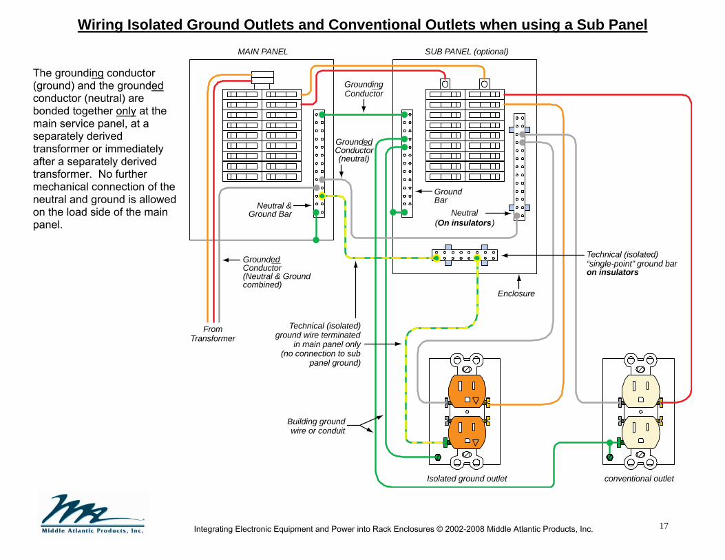
Wiring Isolated Ground Outlets and Conventional Outlets when using a Sub Panel
The grounding conductor (ground) and the grounded conductor (neutral) are bonded together only at the main service panel, at a separately derived transformer or immediately after a separately derived transformer. No further mechanical connection of the neutral and ground is allowed on the load side of the main panel.
Technical (isolated)“single-point” ground baron insulators
MAIN PANEL SUB PANEL (optional)
GroundBarNeutral &
Ground Bar
GroundedConductor(Neutral & Groundcombined)
Neutral(On insulators)
Isolated ground outlet conventional outlet
Technical (isolated)ground wire terminated
in main panel only(no connection to sub
panel ground)
Building groundwire or conduit
Enclosure
FromTransformer
GroundedConductor(neutral)
GroundingConductor
18
Integrating Electronic Equipment and Power into Rack Enclosures © 2002-2008 Middle Atlantic Products, Inc.
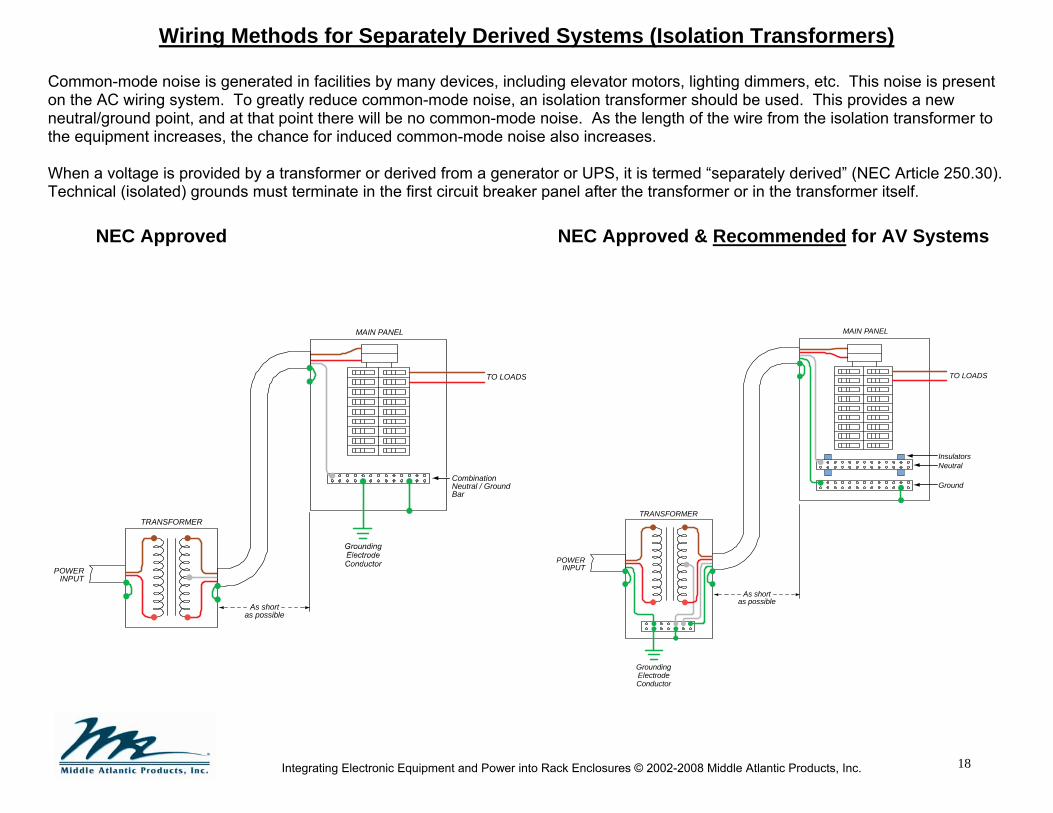
Wiring Methods for Separately Derived Systems (Isolation Transformers)
Common-mode noise is generated in facilities by many devices, including elevator motors, lighting dimmers, etc. This noise is present on the AC wiring system. To greatly reduce common-mode noise, an isolation transformer should be used. This provides a new neutral/ground point, and at that point there will be no common-mode noise. As the length of the wire from the isolation transformer to the equipment increases, the chance for induced common-mode noise also increases. When a voltage is provided by a transformer or derived from a generator or UPS, it is termed “separately derived” (NEC Article 250.30). Technical (isolated) grounds must terminate in the first circuit breaker panel after the transformer or in the transformer itself.
NEC Approved NEC Approved & Recommended for AV Systems
MAIN PANEL
TRANSFORMER
GroundingElectrodeConductor
As shortas possible
InsulatorsNeutral
Ground
TO LOADS
POWERINPUT
MAIN PANEL
TRANSFORMER
CombinationNeutral / GroundBar
TO LOADS
POWERINPUT
As shortas possible
19
Integrating Electronic Equipment and Power into Rack Enclosures © 2002-2008 Middle Atlantic Products, Inc.
K-Rated Power Transformers
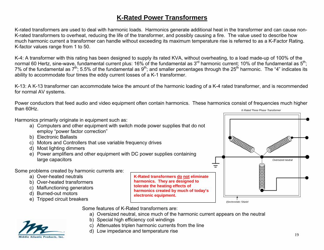
K-rated transformers are used to deal with harmonic loads. Harmonics generate additional heat in the transformer and can cause non-K-rated transformers to overheat, reducing the life of the transformer, and possibly causing a fire. The value used to describe how much harmonic current a transformer can handle without exceeding its maximum temperature rise is referred to as a K-Factor Rating. K-factor values range from 1 to 50. K-4: A transformer with this rating has been designed to supply its rated KVA, without overheating, to a load made-up of 100% of the normal 60 Hertz, sine-wave, fundamental current plus: 16% of the fundamental as 3rd harmonic current; 10% of the fundamental as 5th; 7% of the fundamental as 7th; 5.5% of the fundamental as 9th; and smaller percentages through the 25th harmonic. The “4” indicates its ability to accommodate four times the eddy current losses of a K-1 transformer. K-13: A K-13 transformer can accommodate twice the amount of the harmonic loading of a K-4 rated transformer, and is recommended for normal AV systems. Power conductors that feed audio and video equipment often contain harmonics. These harmonics consist of frequencies much higher than 60Hz. Harmonics primarily originate in equipment such as:
a) Computers and other equipment with switch mode power supplies that do not employ “power factor correction”
b) Electronic Ballasts c) Motors and Controllers that use variable frequency drives d) Most lighting dimmers e) Power amplifiers and other equipment with DC power supplies containing
large capacitors Some problems created by harmonic currents are:
a) Over-heated neutrals b) Over-heated transformers c) Malfunctioning generators d) Burned-out motors e) Tripped circuit breakers
Some features of K-Rated transformers are: a) Oversized neutral, since much of the harmonic current appears on the neutral b) Special high efficiency coil windings c) Attenuates triplen harmonic currents from the line d) Low impedance and temperature rise
K-Rated transformers do not eliminate harmonics. They are designed to tolerate the heating effects of harmonics created by much of today’s electronic equipment.
Oversized neutral
K-Rated Three Phase Transformer
Electrostatic Shield
20
Integrating Electronic Equipment and Power into Rack Enclosures © 2002-2008 Middle Atlantic Products, Inc.
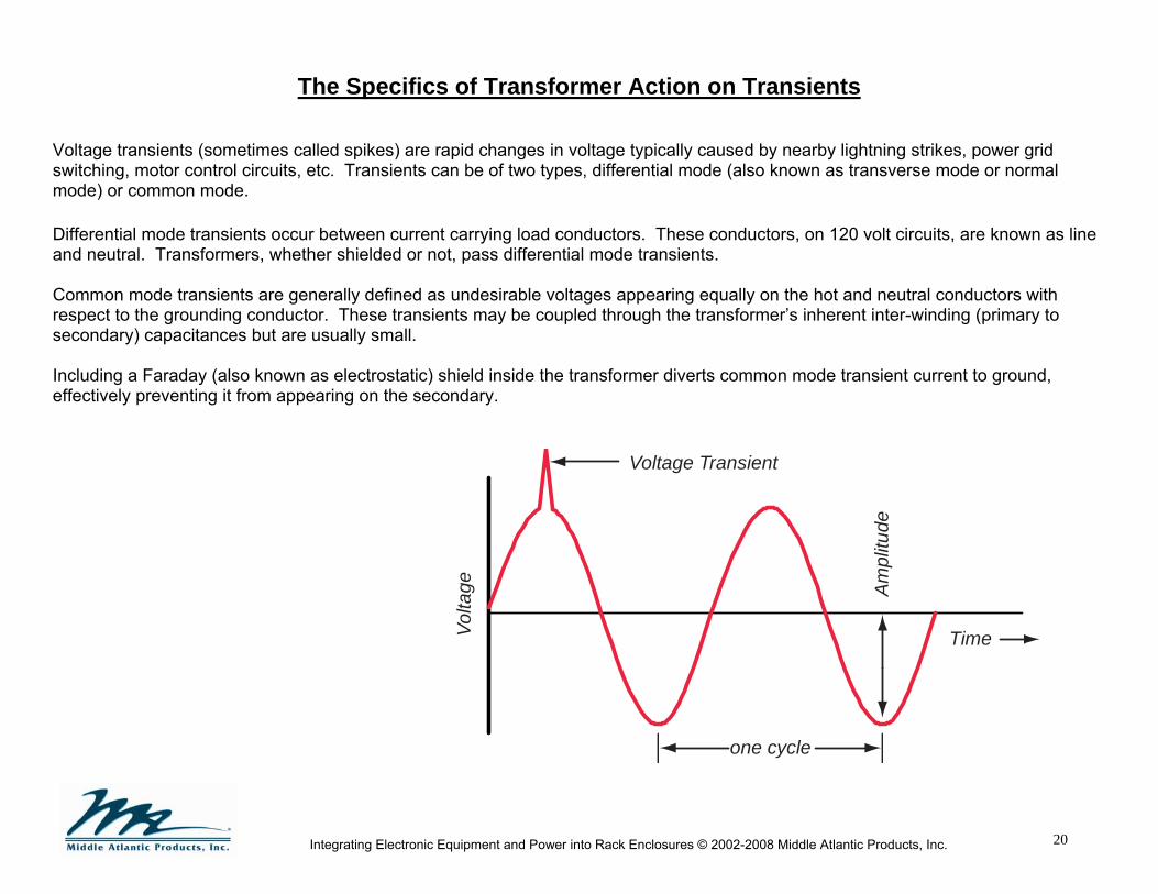
The Specifics of Transformer Action on Transients Voltage transients (sometimes called spikes) are rapid changes in voltage typically caused by nearby lightning strikes, power grid switching, motor control circuits, etc. Transients can be of two types, differential mode (also known as transverse mode or normal mode) or common mode. Differential mode transients occur between current carrying load conductors. These conductors, on 120 volt circuits, are known as line and neutral. Transformers, whether shielded or not, pass differential mode transients. Common mode transients are generally defined as undesirable voltages appearing equally on the hot and neutral conductors with respect to the grounding conductor. These transients may be coupled through the transformer’s inherent inter-winding (primary to secondary) capacitances but are usually small. Including a Faraday (also known as electrostatic) shield inside the transformer diverts common mode transient current to ground, effectively preventing it from appearing on the secondary.
Vo
ltage
one cycle
Ampl
itude
Time
Voltage Transient

21
Integrating Electronic Equipment and Power into Rack Enclosures © 2002-2008 Middle Atlantic Products, Inc.
Electrostatic (Faraday) Shielding in Power Transformers
Electrostatic (Faraday) shields reduce common-mode noise coupling between the primary windings and the secondary windings, improving the isolation.
Load
Noisepath
Standard Power Transformer
Noisepath
Electrostatic Shields
Load
Power Transformer with 2 Electrostatic Shields

22
Integrating Electronic Equipment and Power into Rack Enclosures © 2002-2008 Middle Atlantic Products, Inc.
120V
120V
120V 208V
208V
208V
Grounded Conductor
Typical Three Phase Services
120 / 208 Volt “WYE” 120 / 240 Volt “DELTA” (High Leg)
Always check the line voltage on the circuit supplying your equipment before plugging it in. Although it is not recommended to have a grounded conductor (neutral) in the same circuit breaker panel that also contains a “DELTA” system “High Leg”, there are several systems in the field wired this way. If an electrician mis-wires a circuit using a neutral and high leg, a voltage in excess of 200 volts will appear at what should be a 120-volt outlet! Additionally, if this transformer is shared by other facilities, the neutral/ground currents will also be shared.
240V
240V
240V
High leg
120V
120V
Grounded Conductor
23
Integrating Electronic Equipment and Power into Rack Enclosures © 2002-2008 Middle Atlantic Products, Inc.
Phasing of Supply Conductors When designing power distribution systems under normal circumstances, electrical engineers will balance the loads among all the phase conductors in order to reduce the load on individual phase portions of transformers and circuit breaker panels. This is not always the best design for AV systems.
• Three Phase electrical service is most commonly found in larger commercial and industrial buildings where there are motors, air conditioners and lighting controllers. Due to leakage current and grounded filter capacitors found in most equipment, loads on each phase usually couple a small amount of noise onto the ground circuit. Any device that draws a pulse of current for less than the entire voltage wave generates harmonics. Because the phase conductors are separated by 120 degrees, some of the harmonic current in the neutral conductor is tripled. The additive currents are referred to as “triplen” harmonics.
• Split single phase electrical service is most commonly found in residences and smaller commercial buildings, and can be used to feed AV equipment. One key advantage that single phase has over three phase is that while harmonic currents are still present, it is not possible for the “triplen” components to add in the neutral. In addition, use of split single phase can result in at least a 6 dB reduction in noise floor as compared to three phase if the capacitances of the connected equipment are relatively well balanced.
Note: Video equipment is usually connected using unbalanced shielded cables, and is therefore very sensitive to ground loops. In an installation where the remote cameras are mounted to grounded building structures, the cameras will likely be at a different ground potential than the ground at the monitoring station. This difference in ground potential may induce a ground loop in the camera cable shield. Grounding problems will not be corrected by connecting all equipment to a single phase. To “break” the ground loop, ensure signal transformers are installed, or ensure the camera is isolated from building steel.

24
Integrating Electronic Equipment and Power into Rack Enclosures © 2002-2008 Middle Atlantic Products, Inc.
Symmetrical (Balanced) Power Systems Per NEC 647.1 (2008) the use of a separately derived 120 volt, single phase, 3-wire system with 60 volts between each of the two ungrounded conductors and ground is permitted for the purpose of reducing objectionable noise in sensitive equipment locations, providing the following conditions are met:
1. The system is installed only in commercial or industrial occupancies 2. The system’s use is restricted to areas under close supervision by qualified personnel 3. All other requirements in NEC 647.4 through 647.8 are met
In a 60/120-volt symmetrical balanced power system the load current return path is not a grounded conductor, as it is for the standard 120-volt system. Neutral and safety ground are no longer tied together as in a standard electrical system. Symmetrical (balanced) power transformers do nothing to eliminate differential-mode noise found on the power line Another disadvantage of balanced power systems is the requirement for ground fault circuit interrupter receptacles (GFCI). These receptacles can trip due to normal ground leakage currents, and currents that flow through signal interconnect cables in a system.
120 Volts
Hot
Neutral
Ground
60 Volts
120 Volts
60 VoltsGFCI Typereceptaclerequired
BADIDEA!

25
Integrating Electronic Equipment and Power into Rack Enclosures © 2002-2008 Middle Atlantic Products, Inc.
Symmetrical (Balanced) Power Transformer (cont.)
The less balanced the internal equipment parasitic capacitances are (pairs C1/C2 and C3/C4), the less effective a symmetrical (balanced) power transformer will be at reducing leakage currents, which are a significant cause of noise in unbalanced signal interfaces.
Equipment with 3-Prong Power Cord fed by Symmetrical (Balanced) Power Transformer
Equipment with 2-Prong Power Cord fed by Symmetrical (Balanced) Power Transformer Since the noise reduction achievable with this scheme is typically only 6 to 10 dB, symmetrical (balanced) power transformers are not a cost-effective method of reducing system noise. For reducing noise, it is more cost-effective to ground isolate unbalanced signal interconnections or eliminate them and use balanced signal interconnections which are inherently immune to the effects of leakage currents.
Line
120V
0V
Neutral
60V
60V
C1
C2
C3
C4
Inter-ChassisVoltage
Safety Ground
EquipmentChassis “A”
EquipmentChassis “B”
Line
120V
0V
Neutral
60V
60V
C1
C2
C3
C4
Inter-ChassisCurrent
Safety Ground
EquipmentChassis “A”
EquipmentChassis “B”
26
Integrating Electronic Equipment and Power into Rack Enclosures © 2002-2008 Middle Atlantic Products, Inc.
Ground Myths
Myth #1) An “Isolated Ground” system is not connected to ground. MYTH BUSTED! “Isolated ground” system connects to “ground” (neutral) at the main circuit panel, isolated from any other ground
connections. If equipment is mounted in a rack to conductive rack rails, the rack must also be isolated from any grounds, including concrete or conduit, to function as designed.
Myth #2) A supplemental (auxiliary) ground rod is a place where “noise” wants to go. MYTH BUSTED! Noise will always flow back to the source; noise does not want to flow to ground (earth). In addition the NEC
mandates that any supplemental (auxiliary) ground rod be bonded to the neutral/ground bond of a separately derived system, the main service neutral/ground bond or the grounding electrode system. Improper bonding of a supplemental (auxiliary) ground rod is dangerous! Any attempt to use a supplemental (auxiliary) ground rod as a magical sink for “noise” will most likely result in circulating currents flowing in the ground wires, most likely adding to noise problems. There is no wire from a jet airplane to earth, yet it has an effective grounding system.
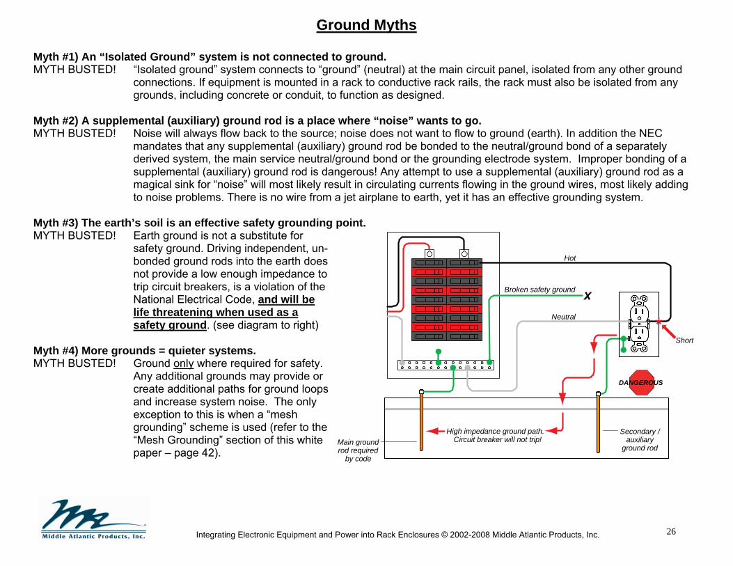
Myth #3) The earth’s soil is an effective safety grounding point. MYTH BUSTED! Earth ground is not a substitute for
safety ground. Driving independent, un-bonded ground rods into the earth does not provide a low enough impedance to trip circuit breakers, is a violation of the National Electrical Code, and will be life threatening when used as a safety ground. (see diagram to right)
Myth #4) More grounds = quieter systems. MYTH BUSTED! Ground only where required for safety.
Any additional grounds may provide or create additional paths for ground loops and increase system noise. The only exception to this is when a “mesh grounding” scheme is used (refer to the “Mesh Grounding” section of this white paper – page 42).
Short
High impedance ground path. Circuit breaker will not trip!
Hot
Neutral
Broken safety ground
DANGEROUS
Main groundrod required
by code
Secondary /auxiliary
ground rod

27
Integrating Electronic Equipment and Power into Rack Enclosures © 2002-2008 Middle Atlantic Products, Inc.
Grounding Gone Bad
Supplemental (auxiliary) grounding electrodes (building steel, ground rods, etc.) are not required or recommended because they may cause severe ground loops and may also be a safety hazard if not bonded properly.
Do not install multiple ground rods or additional ground rods, except as required per code. Supplemental (auxiliary) grounding via a ground rod or building steel is allowed by the NEC, though it must be bonded to the main safety ground (Article 250 III). Never bond an isolated ground wire to a ground rod or building steel. The grounding conductor (ground) and the grounded conductor (neutral) are bonded together only at the main service panel, at a separately derived transformer or immediately after a separately derived transformer. No further connection of the neutral and ground is allowed on the load side of the main panel or the separately derived system transformer.
120/240 VoltMain circuit
breaker panel
Powerstrip
Buss bar
Equipment
BADIDEA!
AuxiliaryGround Rod

28
Integrating Electronic Equipment and Power into Rack Enclosures © 2002-2008 Middle Atlantic Products, Inc.
Isolated Ground Power Strip in a Non–Isolated Rack Installing an isolated ground power strip does not necessarily result in a technical (isolated) ground system. An “isolated ground” system installed in this manner does not guarantee a noise-free system, and is defeated by the smallest breach of isolation via a stray ground. When an isolated grounding system is breached, current will flow in the shields of the signal interconnect cables, inducing noise into the signal conductors. Rackmounted equipment and connector panels, including cable shields, must be isolated from the rack.
Conduit bondedto building
safety ground
Isolatedgroundpowerstrip
120/240 Volt maincircuit breaker
panelSingle-pointtechnical(isolated)
groundingconductors
terminate inthis panel
Conduitcan be
bonded torack
SafetyGround
NeutralLineTechnical(Isolated) GroundBuilding GroundWire Nut
To optionalisolatedbuss bar
This is not recommended
Rack can sitdirectly on
concrete

29
Integrating Electronic Equipment and Power into Rack Enclosures © 2002-2008 Middle Atlantic Products, Inc.
Isolated ground power strip in a non-isolated rack (cont.) A problem will exist due to the fact that all equipment with a 3-prong (grounded) plug has the power cord ground conductor bonded to the chassis. When this rackmounted equipment is screwed to the rackrail, an inadvertent ground connection will be present, defeating the isolation! To avoid these problems when power to equipment is provided via an isolated ground power strip, the building safety ground (that is attached to the rack) must be segregated from the isolated technical ground. This is accomplished by installing non-conductive shoulder washers behind the equipment faces, as shown below. This scheme is hard to implement and is easily rendered ineffective. Note: Technically, even when using isolating washers, higher frequencies will couple through the capacitance of the washer.
Non-ConductiveShoulderWasher
Rack Screwwith Integral
Non-ConductiveWasher
EquipmentMounting
Ears
ThreadedRackrail
Rack MountedEquipment
Rack MountedEquipment
(after installation)
Rack Ear Insulators

30
Integrating Electronic Equipment and Power into Rack Enclosures © 2002-2008 Middle Atlantic Products, Inc.
Isolated Rack with Standard (not isolated) Power Strip
Isolate the entire equipment rack by connecting the conduit that feeds the rack via a non-metallic connection. A technical (isolated) ground conductor must be installed in this conduit and must also be bonded to the rack‘s ground stud. When the rack is sitting on or bolted to a semi-conductive surface, such as concrete, care should be taken to isolate the rack from the floor and mounting bolts. In some installations, it only takes a few milliamps of current to produce a noise problem. Isolating shoulder washers for installation of floor mounting bolts should be used. Rackmounted equipment does not have to be isolated from the rack. However, “non-technical” metallic connections (stray grounds) must be isolated from the rack. An “isolated ground” power strip may be substituted for the standard one, but there is additional cost and no additional benefit.
* If the installation is in close proximity to RF sources (i.e. radio or TV transmitters), mesh grounding may be the best design. Please see the “Mesh Grounding” section of this white paper (page 42).
Conduit bondedto building
safety ground
StandardPowerstrip (notisolatedgroundoutlets)
OptionalBuss bar
Main circuit breakerpanel
Single-pointtechnical (isolated)
grounding conductorsterminate in this panel
Noinsulators
required
NeutralLineTechnical(Isolated) GroundWire NutIndicates Isolation
To optionalbuss bar
This is highly effective and is recommended*
Rack is isolatedfrom floor
Rack Isolation Kit
Mounting bolt
Isolatingshoulderwasher
Rackbottom
Isolator
Use non-conductive (PVC)conduit fittings to isolate
the conduit from the rack;allowed per NEC 640.23(B)
Bonding jumperto ground stud

31
Integrating Electronic Equipment and Power into Rack Enclosures © 2002-2008 Middle Atlantic Products, Inc.
Flexible Connections to Isolated Equipment Racks
In the following examples, the racks are grounded via a technical (isolated) ground, and isolated from the building safety ground. Additionally, these racks are isolated from the floor by use of insulated leveling feet (example 1), and rubber or plastic wheels (example 2, next page). Since power strip mounting hardware cannot be relied upon to conduct fault current, a bonding jumper must be installed between the power strip chassis and the rack. Example 1: With this “hardwired” power strip the bonding connection is between the technical (isolated) grounding conductor (in the junction box), and the rack.
Leveling Feet withIsolating Plastic Caps
Equipment
StandardPower Strip(not isolated
ground outlets)
BondingJumper
Non-MetallicFitting
FlexibleConduit
Example #1
Building Ground
TechnicalGround Hot Neutral
Line 1
Neutral
Building Ground
Technical (isolated)ground
Indicates Isolation

32
Integrating Electronic Equipment and Power into Rack Enclosures © 2002-2008 Middle Atlantic Products, Inc.
Flexible Connections to Isolated Equipment Racks (cont’d)
Example 2: With this “cord connected” power strip the bonding connection is between the power strip chassis and the rack. Note: since the power strip is plugged into an isolated ground style outlet the power strip chassis is grounded via an isolated ground.
Isolating Plastic Or RubberWheels
Technical(Isolated)GroundOutlet
RubberCord
Standard(not isolatedground outlets)Power Strip
Example #2
Equipment
BondingJumper Technical (isolated)
ground
Indicates Isolation

33
Integrating Electronic Equipment and Power into Rack Enclosures © 2002-2008 Middle Atlantic Products, Inc.
Metal-clad cable, commonly known as “MC”.
NEC article: 330
While the NEC allows the use of abare ground wire, the best wire forAV installations is MC with an insulatedground wire. The outer sheath is not tobe used as the primary ground; it issupplemental to the ground wire.
Conduit must be installed as acomplete system before the wiring isinstalled. The conduit is considereda “grounding conductor”. Asupplemental grounding conductormay be installed.
For AV installations it is recommendedto use an insulated ground wire whenmetallic conduit is required or specified.
NEC article: 358 (EMT)NEC article: 342 (IMC)NEC article: 344 (RIGID)
AC Wiring Types
The NEC does not require a supplemental (auxiliary) equipment grounding conductor in metallic conduit (raceway). However, it is highly recommended to add an insulated grounding conductor. Without a supplemental (auxiliary) grounding conductor the integrity of the ground is dependent on all of the conduit fittings in series. If one fitting is loose or corroded, the safety ground system is compromised. Additionally, noise may be induced into the signal path. Pulling a supplemental (auxiliary) equipment grounding conductor, along with the power conductors, assures a low impedance ground path for fault current. The supplemental (auxiliary) equipment grounding conductor must be installed in the conduit with the power conductors. 1. MC cable is manufactured in both steel and aluminum. “Steel-Clad MC” cable with insulated ground wire is the best choice for
AV systems. It has twisted conductors that help reduce AC magnetic fields, however the steel jacket is what helps most. 2. Electrical metallic tubing (commonly known as “EMT” or Thin-Wall) 3. Intermediate metal conduit (commonly known as “Threaded Thin-Wall”) 4. Rigid metal conduit (commonly known as “Rigid”) 5. Flexible metallic tubing 6. Flexible metal conduit (commonly known as “Greenfield”) 7. Liquidtight flexible metal conduit (commonly known as “Liquidtight” or “Sealtight”)
NEC article: 360 (FMT)NEC article: 348 (FMC)NEC article: 356 (LFMC)
This type of raceway has limits as to theuse of the conduit as a groundingconductor. A supplemental groundingconductor is generally required onlengths over 6 ft.
For AV installations it is recommendedto use an insulated ground wire whenmetallic conduit is required or specified.

34
Integrating Electronic Equipment and Power into Rack Enclosures © 2002-2008 Middle Atlantic Products, Inc.
AC Magnetic Field Strengths from Different Wiring Types & Plug-In Power Supplies (Wall-Warts)
Field strength, in milligauss, is a unit of measurement of AC magnetic fields. Not to be mistaken for static magnetic fields like the souvenir magnet on the fridge at home, AC magnetic fields are produced by AC electrical current flow and are a component of Electromagnetic Fields. These fields are notorious for getting into the signal path, creating “hum”. The following measurements show the AC magnetic fields of different wiring types at a specified distance from the signal wires.
Note: While any twist of current-carrying conductors reduces emitted electromagnetic fields, the more twists per length, the greater the reduction.
24 Volt Wall-wart, transformer type24 Volt Wall-wart, transformer type6 Volt Wall-wart, transformer type6 Volt Wall-wart, transformer typeConductor only, not in conduitRomex1" EMT1/2" EMT1/2" RigidRubber Cord, approx. 2" twist1/2" steel-clad spiral MCTHHN, 1" twist, no conduitTHHN, 1/2" twist, no conduit
1/2”Away
2”AwayWire Type
Single #1212-212-212-212-214-312-212-312-3
none.06A (7.2 watts)none.01A (1.2 watts)7.5A (900 watts) not in proximity to return conductor7.5A (900 watts)7.5A (900 watts)7.5A (900 watts)7.5A (900 watts)7.5A (900 watts)7.5A (900 watts)7.5A (900 watts)7.5A (900 watts)
26027014714518012.06.92.71.51.20.60.30.1
10113256701357.24.61.70.90.40.10.20.0
Resistive Load@ 12OVCasing
milligauss reading

35
Integrating Electronic Equipment and Power into Rack Enclosures © 2002-2008 Middle Atlantic Products, Inc.
AC Magnetic Fields & Their Effect on Signal Wiring: Diagnosing Hum and Buzz
Cable shields do not protect against low frequency AC magnetic fields. When diagnosing signal problems caused by low frequency AC electromagnetic fields, it is helpful to short the source end of the signal cable. If a signal cable with a shorted source end hums and the hum goes away when the short is lifted then the interfering field is likely to be an AC magnetic one. AC magnetic fields generally sound like “hum,” electrical fields and high order triplen harmonics generally sound like “buzz.” Note: stationary permanent magnets cannot affect the signal path. There are two effective ways to reduce the effect of AC magnetic fields on the signal path: 1. Physical separation of at least 2” between untwisted signal and power conductors 2. Use tightly twisted signal wire and twisted AC power cables
HumShort
AC magnetic field
Quiet
Open
AC Magnetic field
36
Integrating Electronic Equipment and Power into Rack Enclosures © 2002-2008 Middle Atlantic Products, Inc.
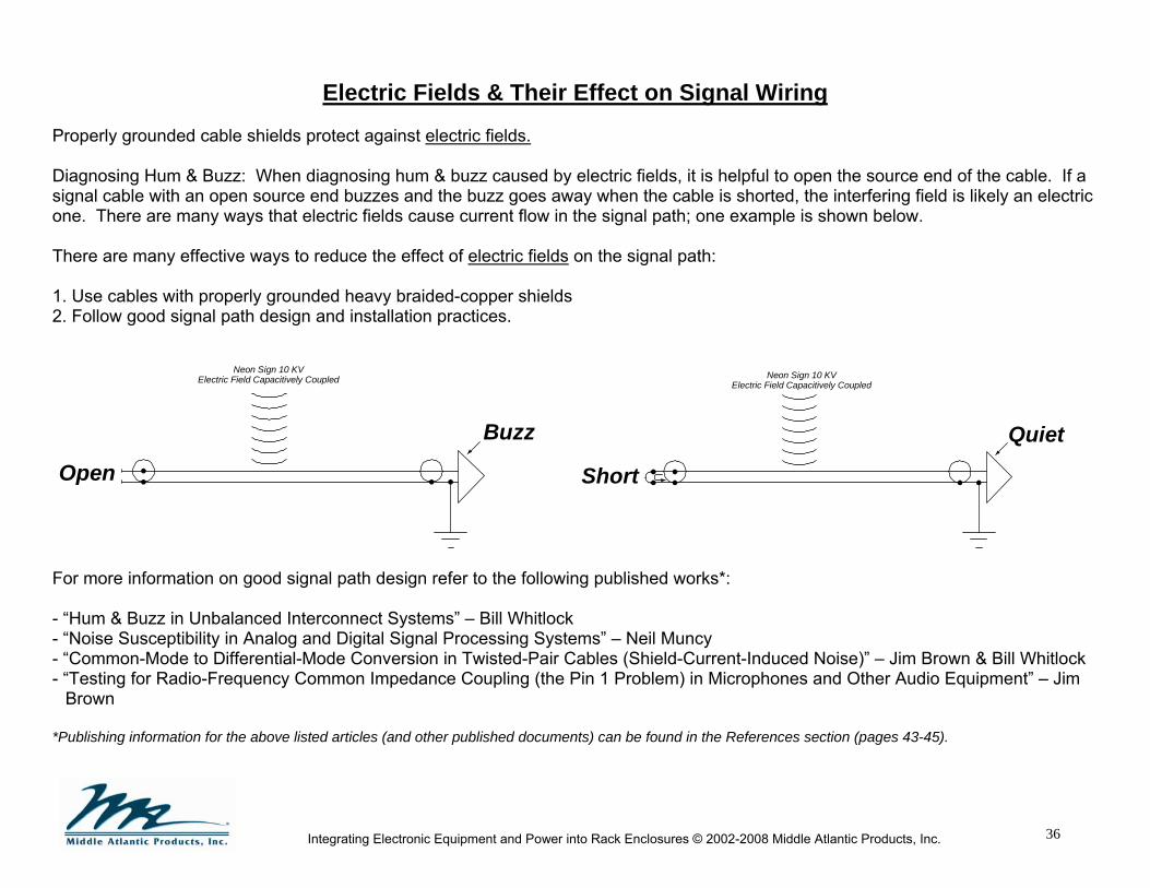
Electric Fields & Their Effect on Signal Wiring Properly grounded cable shields protect against electric fields. Diagnosing Hum & Buzz: When diagnosing hum & buzz caused by electric fields, it is helpful to open the source end of the cable. If a signal cable with an open source end buzzes and the buzz goes away when the cable is shorted, the interfering field is likely an electric one. There are many ways that electric fields cause current flow in the signal path; one example is shown below. There are many effective ways to reduce the effect of electric fields on the signal path: 1. Use cables with properly grounded heavy braided-copper shields 2. Follow good signal path design and installation practices.
For more information on good signal path design refer to the following published works*: - “Hum & Buzz in Unbalanced Interconnect Systems” – Bill Whitlock - “Noise Susceptibility in Analog and Digital Signal Processing Systems” – Neil Muncy - “Common-Mode to Differential-Mode Conversion in Twisted-Pair Cables (Shield-Current-Induced Noise)” – Jim Brown & Bill Whitlock - “Testing for Radio-Frequency Common Impedance Coupling (the Pin 1 Problem) in Microphones and Other Audio Equipment” – Jim
Brown *Publishing information for the above listed articles (and other published documents) can be found in the References section (pages 43-45).
Buzz
Open
Neon Sign 10 KVElectric Field Capacitively Coupled
Quiet
Short
Neon Sign 10 KVElectric Field Capacitively Coupled
37
Integrating Electronic Equipment and Power into Rack Enclosures © 2002-2008 Middle Atlantic Products, Inc.
Signal Wiring: Unbalanced & Balanced Interfaces Long runs of unshielded and untwisted conductors are susceptible to external noise coupling because they behave as antennas. A signal in a conductor can be coupled as noise to adjacent conductors running in close proximity. Telecommunications network cabling can also conduct EMI noise generated from internal sources and radiate or couple the EMI noise to other conductors. Careful attention to audio or video system grounding can certainly reduce the severity of system noise problems. But, regardless of how intelligently we implement system grounding and power distribution, two system “facts of life” remain:
1. Tiny voltages will always exist between pieces of grounded equipment, and 2. Tiny currents will always flow in signal cables connecting ungrounded equipment.
As a result, small power line “noise” currents will always flow in the signal cables that interconnect equipment. In an ideal world, if all equipment had well designed balanced interfaces, these currents would not be a concern at all. However, real-world equipment isn’t perfect and can’t totally prevent coupling of noise into signal circuits as these currents flow in signal cables. Generally, the noise is heard as hum or buzz in audio and seen as hum bars in video. Shield current can be attenuated by routing wires near a ground plane, since the electromagnetic field is confined to the small space between the signal conductor and the ground plane. UNBALANCED interfaces are widely used in consumer electronics and generally use RCA connectors. Unbalanced interfaces are very sensitive to noise currents! Because the grounded conductor (generally the cable shield) is a path for both the audio signal and power-line noise current, any noise voltage drop over its length, due to its resistance, is directly added to the signal. This mechanism, called common-impedance coupling, is responsible for the majority of noise problems in unbalanced interfaces. Therefore, reducing the resistance of the shield conductor can reduce noise. Some tips to lower noise:
- Obviously, avoid unbalanced interfaces whenever possible! - Keep cables short – those over a few feet long are potential problems - Use cables with heavy braided-copper shields instead of foil and drain wire - Use a high-quality signal isolation transformer at the receive end of the cable - Do not disconnect the shield at either end of any unbalanced cable
38
Integrating Electronic Equipment and Power into Rack Enclosures © 2002-2008 Middle Atlantic Products, Inc.
Signal Wiring: Unbalanced & Balanced Interfaces (cont.) BALANCED interfaces are widely used in professional audio equipment and generally use XL connectors. Balanced interfaces have substantial immunity to noise currents! Since the impedances of the two audio signal conductors is the same, noise from any source is coupled to them equally and can be rejected by the receiving input. Power line noise current will harmlessly flow in the cable shield, if present. However, some equipment is of poor design and can create noise coupling problems in real-world systems. Some tips: ► Identify equipment having a “pin 1 problem” using the simple “hummer” test (http://www.iso-max.com/as/as032.pdf) ► If necessary to circumvent a “pin 1 problem,” disconnect the shield only at the receive end of the cable ► If noise rejection is inadequate, use a high-quality signal isolation transformer at the receive end of the cable Henry Ott has published a thorough and insightful analysis of both balanced and unbalanced interfaces. The paper – Balanced vs. Unbalanced Audio Interconnections – examines the practical application of both types of connection, and provides installation best practices in each case. The paper is available at: http://www.hottconsultants.com/pdf_files/Audio%20Interconnections.pdf Furthermore, an in-depth technical discussion of these topics by Bill Whitlock, including step-by-step troubleshooting procedures, is available at: www.jensentransformers.com/an/generic%20seminar.pdf. Remember that signal cable shields are NOT intended to function as a safety ground! Safety grounding must be accomplished by the grounding conductor in the power cord. NEVER LIFT, OR OTHERWISE BYPASS THE POWER CORD GROUND… IT COULD BE FATAL!!

39
Integrating Electronic Equipment and Power into Rack Enclosures © 2002-2008 Middle Atlantic Products, Inc.
Single-Point Technical (Star) Ground vs. Daisy-Chain Grounding of Racks
Two common methods of bonding racks together with equipment grounding conductors are known as “star” grounding and “daisy chain” grounding.
When properly configured, an isolated ground (also known as a technical ground or single-point ground) system is arranged electrically in a “star” pattern. Each rack is bonded to a common single point ground with separate equipment grounding conductors, reducing voltage drop. If paint-piercing hardware is not utilized while ganging racks together, “star” grounding is the recommended design. If the installation is in close proximity to RF sources (i.e. radio or TV transmitters), mesh grounding may be the best design. Please see the “Mesh Grounding” section of this white paper (page 42).
When racks are connected in a “daisy chain” fashion, series resistances in the equipment grounding conductors can increase at each bond point. This can lead to potential differences between racks, which may lead to ground loops that interfere with the system’s performance. This is not recommended unless paint-piercing hardware is used to gang the racks together.
“Star” Grounding (isolated or technical ground)
FloorIsolators
Main ground buss (isolated from building ground)
Metallicconnectors
(stray grounds)and conduits
must be isolatedfrom racks
“Daisy Chain” Grounding
FloorIsolators
Metallicconnectors
(stray grounds)and conduits
must be isolatedfrom racks

40
Integrating Electronic Equipment and Power into Rack Enclosures © 2002-2008 Middle Atlantic Products, Inc.
Enhanced EMC Rack Bonding
Routing signal conductors adjacent or close to a ground plane is a very effective and proven method of reducing the undesirable effects of EMC in signal conductors (since the electromagnetic field is confined to the small space between the signal conductor and the ground plane). The greater the surface area of the ground plane, the lower the impedance and the more effective the protection, especially at higher frequencies. Metal chassis of racks are required by code to be bonded to ground for safety. One of the most effective ways to create a large surface area ground plane is to bond these grounded equipment racks together. One method is to grind the protective paint (or powder coat) from the ganging points where the racks join, and subsequently bolt the racks together. However, grinding exposes the base metal, which will then be subject to corrosion, defeating the intended purpose. When “paint-piercing” hardware is used to gang racks together, the opportunity for corrosion is minimized. Daisy-chain grounding techniques between the racks can then also be used without the possible associated disadvantage of additive resistances. Most electrical inspectors in the United States want to see bonding wires connected to the rack’s grounding lug, so the elimination of the daisy-chain depends on the field requirements.
Note: Daisy-chain grounding can be used in conjunction with paint-piercing hardware, as shown in the above diagram.
FloorIsolators
(required) (optional)
Paint-piercing hardwarefor ganging & bonding racks

41
Integrating Electronic Equipment and Power into Rack Enclosures © 2002-2008 Middle Atlantic Products, Inc.
Introduction to Star Grounding, Signal Reference Grids & Mesh Grounding Paragraph 5.3.2 of CEI/IEC Technical Report 61000-5-2 states “The earthing network is generally designed and implemented by the facility builder to have an impedance as low as possible in order to divert the power fault currents as well as the HF currents without passing through the electronic apparatus or systems. Different earthing network layouts exist and may give satisfaction to their users.” Note that there is no one “right way” to develop an earthing/ground network. Ideally, we would want all points in the earthing network connected together through a low impedance system, effective at all frequencies. This would minimize any potential difference between points. There are two specific methodologies that are often used to create this earthing network:
1. Single Point Ground a. Daisy-Chain: If racks are bonded together in a daisy chain fashion (i.e., Ground A is connected to Ground B, Ground B is
connected to Ground C, Ground C is connected to Ground D, etc.), resistances can add at each bond connection. b. Star (isolated): In this method, all ground connections are joined at a single point. The resistance between each ground
connection and that point is minimized. Longer runs of cable will however have higher resistance than shorter runs. 2. Multi-point Ground
a. Mesh / Plane: In these systems all points are, effectively, connected to each other.
Star/Isolated Grounding In a star connection, ground points are all connected to a single point. The resistance (and the low frequency potential difference) between a rack and the ground point is the minimum, since the connection is direct. The resistance between two racks will, however, not be the minimum since the length of the connection from one rack to another is the sum of the resistance from one rack to ground, added to the resistance from ground to the second rack. In addition, Star systems can act as antennas. This is a significant problem in a facility that is near a source of RFI (such as a radio station), where the RF signal can cause large potential differences. Connecting endpoints in the star to each other would reduce the resistance but would, again, create a ground loop. To eliminate signal interconnection ground loops the grounded shields of the interconnecting cables are often lifted at one end. In balanced interfaces however, lifting one end of a signal cable shield (also done to circumvent a pin 1 problem) can cause the shield to act as an antenna providing entry for voltage anomalies as well as RF interference. To provide a safe path for RF noise it is recommended to put a .01uF to .1uF capacitor (creating a hybrid ground) between the ungrounded end of the shield and ground. Some connectors with in-built RF bypass capacitors are available - see the EMC Series connectors at www.neutrik.com for examples.

42
Integrating Electronic Equipment and Power into Rack Enclosures © 2002-2008 Middle Atlantic Products, Inc.
Signal Reference Grids One way to implement a low impedance ground that is effective over a wide frequency range is to use a copper floor, with all racks and equipment bonded directly to it. Unfortunately, solid copper floors are impractical for many reasons (cost, manufacturability, etc.), so grounding grids are used instead. This topology is commonly known by a few names: signal reference grid, signal reference ground, and a zero signal reference ground (ZSRG). The grounding grid approximates a copper ground plane using a mesh of interconnected copper bars or conductors. These conductors are often installed just under a raised floor surface. The grounding grid is then connected to the building safety ground.
Mesh Grounding The figure to the right illustrates the topology of an effective mesh ground network. In a mesh connection, whether it is produced by a grounding grid or by ground wire interconnections, the impedance between any two points is minimized. Since there are multiple paths between any two racks, the ground current (and therefore, the potential voltage drop) in any one path is minimized. Mesh grounding may be required for sensitive digital and RF equipment found in telecom and other critical industries where higher frequencies are present. Note that creating a set of mesh connections can be logistically difficult and may increase the cost of an installation. For a more detailed insight consult: Lewis, Warren H. Handbook of Electromagnetic Compatibility. Chapter 8, Grounding and Bonding. Edited by Reinaldo Perez: Academic Press, Inc. 1995 Good engineering practices should always be used to properly ground an installation. EMC Directive 2004/108/EC of the European Parliament states “It should be possible to use harmonized standards for fixed installations in order to demonstrate conformity with the essential requirements covered by such standards.” Further, “A fixed installation shall be installed applying good engineering practices and respecting the information on the intended use of its components, with a view to meeting the protection requirements …” Generally, Star/Isolated Ground connections, which are recognized as good engineering practices in the US, are not usually recognized by the European regulatory agencies as good engineering practices. However, when properly employed Star/Isolated Ground connections or Mesh connections are effective means of minimizing ground currents and noise in electrical systems.
ElectronicEquipmentRack
ElectronicEquipmentRack
ElectronicEquipmentRack
ElectronicEquipmentRack
Grounding ElectrodeSystem
Main Ground Bus
Electrical bondto mesh
NEC required safetygrounding conductor
Mesh Ground Network

43
Integrating Electronic Equipment and Power into Rack Enclosures © 2002-2008 Middle Atlantic Products, Inc.
Authors This document was written by and in collaboration with: Henry W. Ott, MSEE – Principle Consultant, Henry Ott Consultants Bill Whitlock – President & Chief Engineer, Jensen Transformers Bruce Olson – President, Olson Sound Design Neil Muncy – President, Neil Muncy Associates Daryl Ebersole, P.E. – Fournier, Robson & Associates, LLC Bob Schluter – President & Chief Engineer, Middle Atlantic Products Jim Herrick – Senior Design Engineer, Power Products, Middle Atlantic Products (N.J. Elect. Cont Lic 6748 / Elect Insp Lic 7702) Murray Williams – Product Manager, Electrical and Electronic, Middle Atlantic Products Peter Skinner, BSEE – Electronic Development Engineer, Middle Atlantic Products Richard Lefkowitz, MSEE – Manager, Electrical and Electronic Engineering, Middle Atlantic Products Edited by: Rebeca Trautner – Middle Atlantic Products References Information copied from the National Electrical Code (NEC) was reprinted with permission from NFPA 70, The National Electrical Code, © 2008. National Fire Protection Association, Quincy, MA 02269. Directive 2004/108/EC of the European Parliament and of the Council of 15 December 2004 on the approximation of the laws of the member states relating to electromagnetic compatibility and repealing Directive 89/336/EEC BICSI Telecommunications Distribution Methods Manual, 10th Edition IEC 61000-5-2 Electromagnetic Compatibility (EMC) Part 5: Installation and Mitigation Guidelines – Section 2: Earthing and Cabling K-Rated Transformer, I-Trap, Shielded Isolation Transformer material was provided by Acme Electric Corporation.
Additional K-Rated Transformer information from Controlled Power Company and Federal Pacific
Atkinson, Charles & Philip Giddings. “Grounding Systems and their Implementation.” Journal of the Audio Engineering Society, Vol. 43, No. 6, June 1995.

44
Integrating Electronic Equipment and Power into Rack Enclosures © 2002-2008 Middle Atlantic Products, Inc.
References (cont.) Bohn, Dennis. “Why Not Wye?” RaneNote 109, Rane Corporation, 1991. Bohn, Dennis. “Interfacing Audio & POTS.” RaneNote 150, Rane Corporation, 2002. Brown, Jim. “Testing for Radio-Frequency Common Impedance Coupling (the “Pin 1 Problem”) in Microphones and Other Audio Equipment.” New York, NY: AES 115th Convention, October 10-13, 2003. Brown, Jim. “Shield Current Induced Noise Causes & Solutions.” Synergetic Audio Concepts, Inc. Vol. 31 No. 3 Summer 2003. Brown, Jim. “Shield Current Induced Noise Causes & Solutions Part 2.” Synergetic Audio Concepts, Inc. Vol. 32 No. 1 Winter 2004. Brown, Jim. “Pin 1 Revisited.” Synergetic Audio Concepts, Inc. Brown, Jim. “Pin 1 Revisited Part 2.” Synergetic Audio Concepts, Inc. Brown, Jim & Bill Whitlock. “Common-Mode to Differential-Mode Conversion in Shielded Twisted-Pair Cables (Shield-Current-Induced Noise).” Amsterdam, The Netherlands: AES 114th Convention, March 2003. Burdick, Allen H. “A Clean Audio Installation Guide.” Syracuse, NY: Benchmark Media Systems, 1997. Giddings, Philip. Audio Systems Design and Installation. Woburn, MA: Butterworth-Heinemann, 1990. Giddings, Philip. “Power and Ground Update.” Toronto, Canada: February 15, 1996. Holt, Mike. Grounding & Bonding NEC 250. Tamarac, FL: Mike Holt Enterprises Inc. August 2002. Holt, Mike. Grounding Versus Bonding. Mike Holt Enterprises Inc. 2005. Lewis, Warren H. Handbook of Electromagnetic Compatibility. Chapter 8, Grounding and Bonding. Edited by Reinaldo Perez: Academic Press, Inc. 1995 Macatee, Stephen R. “Considerations in Grounding and Shielding Computer-Controlled Audio Devices.” Mukilteo, WA: Rane Corporation, AES 13th International Conference, pp 135-139.

45
Integrating Electronic Equipment and Power into Rack Enclosures © 2002-2008 Middle Atlantic Products, Inc.
References (cont.) Morrison, Ralph. Grounding and Shielding Techniques Fourth Edition. New York, NY: John Wiley & Sons, 1998. Morrison, Ralph. Noise and Other Interfering Signals. New York, NY: John Wiley & Sons, 1991 Morrison, Ralph & Warren H. Lewis. Grounding and Shielding in Facilities. York, NY: John Wiley & Sons, 1990. Muncy, Neil. “Noise Susceptibility in Analog and Digital Signal Processing Systems.” Journal of the Audio Engineering Society, Vol. 43, No. 6, June 1995, pp. 435-453. Muncy, Neil. “Star Grounds, Loop Areas, and Electrical Safety in Project Studios, Edit Suites, & Other Compact Audio Installations.” Toronto, Canada: December 15, 2001. Ott, Henry W. Noise Reduction Techniques in Electronic Systems Second Edition. New York, NY: John Wiley & Sons, 1988. Rane Technical Staff. “Sound System Interconnection.” RaneNote 110, Rane Corporation, 1985, 1995, 2006. Simmons, J. Philip. Soares Book on Grounding (7th Edition). Richardson, Texas: International Association of Electrical Inspectors. Whitlock, Bill. “Understanding, Finding, & Eliminating Ground Loops in Audio & Video Systems.” http://www.jensentransformers.com/an/generic%20seminar.pdf Chatsworth, CA: Jensen Transformers, Inc. 2005 www.jensen-transformers.com. Whitlock, Bill. “Hum & Buzz in Unbalanced Interconnect Systems.” http://www.jensen-transformers.com/an/an004.pdf Chatsworth, CA: Jensen Transformers, Inc. www.jensen-transformers.com. Whitlock, Bill. “System Problems and Equipment Manufacturers.” Systems Contractor News, September 1997.

46
Integrating Electronic Equipment and Power into Rack Enclosures © 2002-2008 Middle Atlantic Products, Inc.
Notes
This page is for your convenience to make notes and drawings.
________________________________________________________________________________________________________________________________________________
________________________________________________________________________________________________________________________________________________
________________________________________________________________________________________________________________________________________________
________________________________________________________________________________________________________________________________________________
________________________________________________________________________________________________________________________________________________
________________________________________________________________________________________________________________________________________________

47
Integrating Electronic Equipment and Power into Rack Enclosures © 2002-2008 Middle Atlantic Products, Inc.
Notes
This page is for your convenience to make notes and drawings.
________________________________________________________________________________________________________________________________________________
________________________________________________________________________________________________________________________________________________
________________________________________________________________________________________________________________________________________________
________________________________________________________________________________________________________________________________________________
________________________________________________________________________________________________________________________________________________
________________________________________________________________________________________________________________________________________________
48
Integrating Electronic Equipment and Power into Rack Enclosures © 2002-2008 Middle Atlantic Products, Inc.
Notes
This page is for your convenience to make notes and drawings.
________________________________________________________________________________________________________________________________________________
________________________________________________________________________________________________________________________________________________
________________________________________________________________________________________________________________________________________________
________________________________________________________________________________________________________________________________________________
________________________________________________________________________________________________________________________________________________
________________________________________________________________________________________________________________________________________________

49
Integrating Electronic Equipment and Power into Rack Enclosures © 2002-2008 Middle Atlantic Products, Inc.
Copyright ©2002-2008 Middle Atlantic Products, Inc ("Middle Atlantic Products"). All rights reserved. All original information, logos, charts, graphics, images, and/or nomographs herein are the sole property of Middle Atlantic Products.
Warning: Unauthorized reproduction, copying, display or revision of this reference guide, or the information, charts, images and content of the reference guide, is prohibited by federal law and is subject to federal prosecution.
Middle Atlantic Products gives the viewer of this Reference Guide a limited nonexclusive license to view or print this publication. All uses of this Reference Guide must be for non-commercial purposes. The Reference Guide may not be copied or distributed without first obtaining the written permission of Middle Atlantic Products.
This Reference Guide is provided to the user for informational purposes only. Middle Atlantic Products makes NO WARRANTIES of any kind with regard to this document, including but not limited to liability for system failure due to design. The Reference Guide is provided "AS IS" WITHOUT WARRANTY OF ANY KIND, EITHER EXPRESSED OR IMPLIED, INCLUDING, BUT NOT LIMITED TO, THE IMPLIED WARRANTIES OF MERCHANTABILITY, FITNESS FOR A PARTICULAR PURPOSE, OR NON-INFRINGEMENT. Some jurisdictions do not allow the exclusion of implied warranties, so the above exclusion may not apply to you.
Middle Atlantic Products shall not be held liable for any damage, direct or indirect, actual or consequential, that may occur as a result of relying upon, using, following, or circumstances arising out of or in connection with this publication, or information provided, or referenced herein.
Middle Atlantic Products, nor its officers, directors, employees, contributors nor agents shall be held responsible for any errors or omissions in this Reference Guide. Information in this publication is subject to update or change without notice at any time.
References to other companies, their products or services, are provided without ANY WARRANTY OF ANY KIND, EITHER EXPRESSED OR IMPLIED.
Nothing contained in this Reference Guide should be construed as granting any right or license to use, reproduce, transmit, perform, publish, license, modify, rewrite, create derivative works from, transfer, store, or sell the content.
This publication may be accessed by users internationally and may contain references to products or services that are not available in your country. These references do not imply that Middle Atlantic Products intends to, or will make, such products and/or services available in your country.
This document is a guide only. Suggested wiring methods, described herein are not intended to supersede any National or Local codes or regulations. Work must be performed by qualified personnel only, which may include required licensing and inspection of work.

50
Integrating Electronic Equipment and Power into Rack Enclosures © 2002-2008 Middle Atlantic Products, Inc.