Table of Contents - pangonilo.com 2.2 Alternating-current quantities . 2.3 Electrical resistances ....
809
Table of Contents 1 Fundamental Physical and Technical Terms 1.1 Units of physical quantities 1.1.1 The international system of units (SI) 1.1.2 Other units still in common use; metric, British and US measures 1.1.3 Fundamental physical constants 1.2 Physical, chemical and technical values 1.2.1 Electrochemical series 1.2.2 Faraday's law 1.2.3 Thermoelectric series 1.2.4 pH value 1.2.5 Heat transfer 1.2.6 Acoustics, noise measurement, noise abatement 1.2.7 Technical values of solids, liquids and gases 1.3 Strength of materials 1.3.1 Fundamentals and definitions 1.3.2 Tensile and compressive strength 1.3.3 Bending strength 1.3.4 Loading on beams 1.3.5 Buckling strength 1.3.6 Maximum permissible buckling and tensile stress for tubular rods 1.3.7 Shear strength 1.3.8 Moments of resistance and moments of inertia 1.4 Geometry, calculation of areas and solid bodies 1.4.1 Area of polygons 1.4.2 Areas and centres of gravity 1.4.3 Volumes and surface areas of solid bodies 2 General Electrotechnical Formulae 2.1 Electrotechnical symbols as per DIN 1304 Part 1 2.2 Alternating-current quantities 2.3 Electrical resistances 2.3.1 Definitions and specific values 2.3.2 Resistances in different circuit configurations 2.3.3 The influence of temperature on resistance 2.4 Relationships between voltage drop, power loss and conductor cross-section 2.5 Current input of electrical machines and transformers 2.6 Attenuation constant a of transmission systems 3 Calculation of Short-Circuit Currents in Three-Phase Systems 3.1 Terms and definitions 3.1.1 Terms as per DIN VDE 0102 / IEC 909 3.1.2 Symmetrical components of asymmetrical three-phase systems 3.2 Fundamentals of calculation according to DIN VDE 0102 / IEC 909 3.3 Impedances of electrical equipment 3.3.1 System infeed 3.3.2 Electrical machines 3.3.3 Transformers and reactors 3.3.4 Three-phase overhead lines 3.3.5 Three-phase cables 3.3.6 Busbars in switchgear installations 3.4 Examples of calculation 3.5 Effect of neutral point arrangement on fault behaviour in three-phase high-voltage networks over 1 kV 4 Dimensioning Switchgear Installations 4.1 Insulation rating 4.2 Dimensioning of power installations for mechanical and thermal short-circuit strength 4.2.1 Dimensioning of bar conductors for mechanical short-circuit strength 4.2.2 Dimensioning of stranded conductors for mechanical short-circuit strength 4.2.3 Horizontal span displacement 4.2.4 Mechanical stress on cables and cable fittings in the event of short circuit 4.2.5 Rating the thermal short-circuit current capability 4.3 Dimensioning of wire and tubular conductors for static loads and electrical surface-field strength 4.3.1 Calculation of the sag of wire conductors in outdoor installations 4.3.2 Calculation of deflection and stress of tubular busbars 4.3.3 Calculation of electrical surface field strength 4.4 Dimensioning for continuous current rating 4.4.1 Temperature rise in enclosed switchboards
Transcript of Table of Contents - pangonilo.com 2.2 Alternating-current quantities . 2.3 Electrical resistances ....

Table of Contents 1 Fundamental Physical and Technical Terms
1.1 Units of physical quantities 1.1.1 The international system of units (SI) 1.1.2 Other units still in common use; metric, British and US measures 1.1.3 Fundamental physical constants
1.2 Physical, chemical and technical values 1.2.1 Electrochemical series 1.2.2 Faraday's law 1.2.3 Thermoelectric series 1.2.4 pH value 1.2.5 Heat transfer 1.2.6 Acoustics, noise measurement, noise abatement 1.2.7 Technical values of solids, liquids and gases
1.3 Strength of materials 1.3.1 Fundamentals and definitions 1.3.2 Tensile and compressive strength 1.3.3 Bending strength 1.3.4 Loading on beams 1.3.5 Buckling strength 1.3.6 Maximum permissible buckling and tensile stress for tubular rods 1.3.7 Shear strength 1.3.8 Moments of resistance and moments of inertia
1.4 Geometry, calculation of areas and solid bodies 1.4.1 Area of polygons 1.4.2 Areas and centres of gravity 1.4.3 Volumes and surface areas of solid bodies
2 General Electrotechnical Formulae 2.1 Electrotechnical symbols as per DIN 1304 Part 1 2.2 Alternating-current quantities 2.3 Electrical resistances
2.3.1 Definitions and specific values 2.3.2 Resistances in different circuit configurations 2.3.3 The influence of temperature on resistance
2.4 Relationships between voltage drop, power loss and conductor cross-section 2.5 Current input of electrical machines and transformers 2.6 Attenuation constant a of transmission systems
3 Calculation of Short-Circuit Currents in Three-Phase Systems 3.1 Terms and definitions
3.1.1 Terms as per DIN VDE 0102 / IEC 909 3.1.2 Symmetrical components of asymmetrical three-phase systems
3.2 Fundamentals of calculation according to DIN VDE 0102 / IEC 909 3.3 Impedances of electrical equipment
3.3.1 System infeed 3.3.2 Electrical machines 3.3.3 Transformers and reactors 3.3.4 Three-phase overhead lines 3.3.5 Three-phase cables 3.3.6 Busbars in switchgear installations
3.4 Examples of calculation 3.5 Effect of neutral point arrangement on fault behaviour in three-phase high-voltage networks over 1 kV
4 Dimensioning Switchgear Installations 4.1 Insulation rating 4.2 Dimensioning of power installations for mechanical and thermal short-circuit strength
4.2.1 Dimensioning of bar conductors for mechanical short-circuit strength 4.2.2 Dimensioning of stranded conductors for mechanical short-circuit strength 4.2.3 Horizontal span displacement 4.2.4 Mechanical stress on cables and cable fittings in the event of short circuit 4.2.5 Rating the thermal short-circuit current capability
4.3 Dimensioning of wire and tubular conductors for static loads and electrical surface-field strength 4.3.1 Calculation of the sag of wire conductors in outdoor installations 4.3.2 Calculation of deflection and stress of tubular busbars 4.3.3 Calculation of electrical surface field strength
4.4 Dimensioning for continuous current rating 4.4.1 Temperature rise in enclosed switchboards

4.4.2 Ventilation of switchgear and transformer rooms 4.4.3 Forced ventilation and air-conditioning of switchgear installations 4.4.4 Temperature rise in enclosed busbars 4.4.5 Temperature rise in insulated conductors 4.4.6 Longitudinal expansion of busbars
4.5 Rating power systems for earthquake safety 4.5.1 General principles 4.5.2 Experimental verification 4.5.3 Verification by calculation
4.6 Minimum clearances, protective barrier clearances and widths of gangways 4.6.1 Minimum clearances and protective barrier clearances in power systems with rated voltages over 1 kV (DIN VDE 0101) 4.6.2 Walkways and gangways in power installations with rated voltages over 1kV (DIN VDE0101) 4.6.3 Gangway widths in power installations with rated voltages of up to 1 kV (DIN VDE 0100 Part 729)
4.7 Civil construction requirements 4.7.1 Indoor installations 4.7.2 Outdoor installations 4.7.3 Installations subject to special conditions 4.7.4 Battery compartments 4.7.5 Transformer installation 4.7.6 Fire prevention 4.7.7 Shipping dimensions
5 Protective Measures for Persons and Installations 5.1 Electric shock protection in installations up to 1000V as per DIN VDE 0100
5.1.1 Protection against direct contact (basic protection) 5.1.2 Protection in case of indirect contact (fault protection) 5.1.3 Protection by extra low voltage 5.1.4 Protective conductors, PEN conductors and equipotential bonding conductors
5.2 Protection against contact in installations above 1000V as per DIN VDE 0101 5.2.1 Protection against direct contact 5.2.2 Protection in the case of indirect contact
5.3 Earthing 5.3.1 Fundamentals, definitions and specifications 5.3.2 Earthing material 5.3.3 Dimensioning of earthing systems 5.3.4 Earthing measurements
5.4 Lightning protection 5.4.1 General 5.4.2 Methods of lightning protection 5.4.3 Overhead earth wires 5.4.4 Lightning rods
5.5 Electromagnetic compatibility 5.5.1 Origin and propagation of interference quantities 5.5.2 Effect of interference quantities on interference sinks 5.5.3 EMC measures
5.6 Partial-discharge measurement 5.6.1 Partial-discharge processes 5.6.2 Electrical partial-discharge measurement procedures
5.7 Effects of climate and corrosion protection 5.7.1 Climates 5.7.2 Effects of climate and climatic testing 5.7.3 Reduction of insulation capacity by humidity 5.7.4 Corrosion protection
5.8 Degrees of protection for electrical equipment of up to 72.5 kV (VDE 0470 Part 1, EN 60529) 6 Methods and Aids for Planning Installations
6.1 Planning of switchgear installations 6.1.1 Concept, boundary conditions, pc calculation aids 6.1.2 Planning of high-voltage installations 6.1.3 Project planning of medium-voltage installations 6.1.4 Planning of low-voltage installations 6.1.5 Calculation of short-circuit currents, computer-aided 6.1.6 Calculation of cable cross-sections, computer-aided 6.1.7 Planning of cable routing, computer-aided
6.2 Reference designations and preparation of documents 6.2.1 Item designation of electrical equipment as per DIN 40719 Part 2

6.2.2 Preparation of documents 6.2.3 Classification and designation of documents 6.2.4 Structural principles and reference designation as per IEC 61346
6.3 CAD/CAE methods applied to switchgear engineering 6.3.1 Terminology, standards 6.3.2 Outline of hardware and software for CAD systems 6.3.3 Overview of CAD applications in ABB switchgear engineering
6.4 Drawings 6.4.1 Drawing formats 6.4.2 Standards for representation 6.4.3 Lettering in drawings, line thicknesses 6.4.4 Text panel, identification of drawing 6.4.5 Drawings for switchgear installations 6.4.6 Drawing production, drafting aids
7 Low Voltage Switchgear 7.1 Switchgear apparatus
7.1.1 Low voltage switchgear as per VDE 0660 Part 100 and following parts, EN 60947 -... and IEC 60947 7.1.2 Low voltage fuses as per VDE 0636 Part 10 and following parts, EN 60269-... IEC60269- 7.1.3 Protective switchgear for household and similar uses 7.1.4 Selectivity 7.1.5 Backup protection
7.2 Low-voltage switchgear installations and distribution boards 7.2.1 Basics 7.2.2 Standardized terms 7.2.3 Classification of switchgear assemblies 7.2.4 Internal subdivision by barriers and partitions 7.2.5 Electrical connections in switchgear assemblies 7.2.6 Verification of identification data of switchgear assemblies 7.2.7 Switchgear assemblies for operation by untrained personnel 7.2.8 Retrofitting, changing and maintaining low-voltage switchgear assemblies 7.2.9 Modular low-voltage switchgear system (MNS system) 7.2.10 Low-voltage distribution boards in cubicle-type assembly 7.2.11 Low-voltage distribution boards in multiple box-type assembly 7.2.12 Systems for reactive power compensation 7.2.13 Control systems for low-voltage switchgear assemblies
7.3 Design aids 7.4 Rated voltage 690 V 7.5 Selected areas of application
7.5.1 Design of low-voltage substations to withstand induced vibrations 7.5.2 Low voltage substations in internal arc-proof design for offshore applications 7.5.3 Substations for shelter
8 Switchgear and Switchgear Installations for High-Voltage up to and including 52 kV (Medium Voltage) 8.1 Switchgear apparatus (= 52kV)
8.1.1 Disconnectors 8.1.2 Switch-disconnectors 8.1.3 Earthing switches 8.1.4 Position indication 8.1.5 HV fuse links (DIN EN 60 282-1 (VDE 0670 Part 4)) 8.1.6 Is-limiter® - fastest switching device in the world 8.1.7 Circuit-breakers 8.1.8 Vacuum contactors
8.2 Switchgear installations (= 52 kV) 8.2.1 Specifications covering HV switchgear installations 8.2.2 Switchgear as per DIN VDE 0101 8.2.3 Metal-enclosed switchgear as per DIN EN 60298 (VDE 0670 Part 6) 8.2.4 Metal-enclosed air-insulated switchgear as per DIN EN 60298 (VDE 0670 Part 6) 8.2.5 Metal-enclosed gas-insulated switchgear under DIN EN 60298 (VDE 0670 Part 6) 8.2.6 Control systems for medium-voltage substations
8.3 Terminal connections for medium-voltage installations 8.3.1 Fully-insulated transformer link with cables 8.3.2 SF6-insulated busbar connection 8.3.3 Solid-insulated busbar connection
9 High-Current Switchgear 9.1 Generator circuit-breaker
9.1.1 Selection criteria for generator circuit-breakers 9.1.2 Generator circuit-breaker type ranges HG... and HE... (SF6 gas breaker)

9.1.3 Generator circuit-breaker type DR (air-blast breaker) 9.1.4 Generator circuit-breaker type VD 4 G (vacuum breaker)
9.2 High-current bus ducts (generator bus ducts) 9.2.1 General requirements 9.2.2 Types, features, system selection 9.2.3 Design dimensions 9.2.4 Structural design 9.2.5 Earthing system 9.2.6 Air pressure/Cooling system
10 High-Voltage Apparatus 10.1 Definitions and electrical parameters for switchgear 10.2 Disconnectors and earthing switches
10.2.1 Rotary disconnectors 10.2.2 Single-column (pantograph) disconnector TFB 10.2.3 Two-column vertical break disconnectors 10.2.4 Single-column earthing switches 10.2.5 Operating mechanisms for disconnectors and earthing switches
10.3 Switch-disconnectors 10.4 Circuit-breakers
10.4.1 Function, selection 10.4.2 Design of circuit-breakers for high-voltage (>52kV) 10.4.3 Interrupting principle and important switching cases 10.4.4 Quenching media and operating principle 10.4.5 Operating mechanism and control
10.5 Instrument transformers for switchgear installations 10.5.1 Definitions and electrical quantities 10.5.2 Current transformer 10.5.3 Inductive voltage transformers 10.5.4 Capacitive voltage transformers 10.5.5 Non-conventional transformers
10.6 Surge arresters 10.6.1 Design, operating principle 10.6.2 Application and selection of MO surge arresters
11 High-Voltage Switchgear Installations 11.1 Summary and circuit configuration
11.1.1 Summary 11.1.2 Circuit configurations for high- and medium-voltage switchgear installations
11.2 SF6-gas-insulated switchgear (GIS) 11.2.1 General 11.2.2 SF6 gas as insulating and arc-quenching medium 11.2.3 GIS for 72.5 to 800 kV 11.2.4 SMART-GIS 11.2.5 Station arrangement 11.2.6 Station layouts 11.2.7 SF6-insulated busbar links
11.3 Outdoor switchgear installations 11.3.1 Requirements, clearances 11.3.2 Arrangement and components 11.3.3 Switchyard layouts
11.4 Innovative HV switchgear technology 11.4.1 Concepts for the future
11.4.1.1 Process electronics (sensor technology, PISA) 11.4.1.2 Monitoring in switchgear installations 11.4.1.3 Status-oriented maintenance
11.4.2 Innovative solutions 11.4.2.1 Compact outdoor switchgear installations 11.4.2.2 Hybrid switchgear installations
11.4.3 Modular planning of transformer substations 11.4.3.1 Definition of modules 11.4.3.2 From the customer requirement to the modular system solution
11.5 Installations for high-voltage direct-current (HDVC) transmission 11.5.1 General 11.5.2 Selection of main data for HDVC transmission 11.5.3 Components of a HDVC station 11.5.4 Station layout
11.6 Static var (reactive power) composition (SVC) 11.6.1 Applications

11.6.2 Types of compensator 11.6.3 Systems in operation
12 Transformers and Other Equipment for Switchgear Installations 12.1 Transformers
12.1.1 Design, types and dimensions 12.1.2 Vector groups and connections 12.1.3 Impedance voltage, voltage variation and short-circuit current withstand 12.1.4 Losses, cooling and overload capacity 12.1.5 Parallel operation 12.1.6 Protective devices for transformers 12.1.7 Noise levels and means of noise abatement
12.2 Current-limiting reactors EN 60289 (VDE 0532 Part 20) 12.2.1 Dimensioning 12.2.2 Reactor connection 12.2.3 Installation of reactors
12.3 Capacitors 12.3.1 Power capacitors 12.3.2 Compensation of reactive power
12.4 Resistor devices 12.5 Rectifiers
13 Conductor Materials and Accessories for Switchgear Installations 13.1 Busbars, stranded-wire conductors and insulators
13.1.1 Properties of conductor materials 13.1.2 Busbars for switchgear installations 13.1.3 Drilled holes and bolted joints for busbar conductors 13.1.4 Technical values for stranded-wire conductors 13.1.5 Post-type insulators and overhead-line insulators
13.2 Cables, wires and flexible cords 13.2.1 Specifications, general 13.2.2 Current-carrying capacity 13.2.3 Selection and protection 13.2.4 Installation of cables and wires 13.2.5 Cables for control, instrument transformers and auxiliary supply in high-voltage switchgear installations 13.2.6 Telecommunications cables 13.2.7 Data of standard VDE, British and US cables 13.2.8 Power cable accessories for low- and medium- voltage
13.3 Safe working equipment in switchgear installations 14 Protection and Control Systems in Substations and Power Networks
14.1 Introduction 14.2 Protection
14.2.1 Protection relays and protection systems 14.2.2 Advantages of numeric relays 14.2.3 Protection of substations, lines and transformers 14.2.4 Generator unit protection
14.3 Control, measurement and regulation (secondary systems) 14.3.1 D.C. voltage supply 14.3.2 Interlocking 14.3.3 Control 14.3.4 Indication 14.3.5 Measurement 14.3.6 Synchronizing 14.3.7 Metering 14.3.8 Recording and logging 14.3.9 Automatic switching control 14.3.10 Transformer control and voltage regulation 14.3.11 Station control rooms
14.4 Station control with microprocessors 14.4.1 Outline 14.4.2 Microprocessor and conventional secondary systems compared 14.4.3 Structure of computerized control systems 14.4.4 Fibre-optic cables
14.5 Network control and telecontrol 14.5.1 Functions of network control systems 14.5.2 Control centres with process computers for central network management 14.5.3 Control centres, design and equipment 14.5.4 Telecontrol and telecontrol systems

14.5.5 Transmission techniques 14.5.6 Technical conditions for telecontrol systems and interfaces with substations
14.6 Load management , ripple control 14.6.1 Purpose of ripple control and load management 14.6.2 Principle and components for ripple-control systems 14.6.3 Ripple-control command centre 14.6.4 Equipment for ripple control 14.6.5 Ripple control recievers
15 Secondary Installations 15.1 Stand-by power systems
15.1.1 Overview 15.1.2 Stand-by power with generator systems 15.1.3 Uninterruptible power supply with stand-by generating sets (rotating UPS installations) 15.1.4 Uninterruptible power supply with static rectifiers (static UPS installations)
15.2 High-speed transfer devices 15.2.1 Applications, usage, tasks 15.2.2 Integration into the installation 15.2.3 Design of high-speed transfer devices 15.2.4 Functionality 15.2.5 Types of transfer
15.3 Stationary batteries and battery installations, DIN VDE 0510, Part 2 798 15.3.1 Types and specific properties of batteries 15.3.2 Charging and discharging batteries 15.3.3 Operating modes for batteries 15.3.4 Dimensioning batteries 15.3.5 Installing batteries, types of installation
15.4 Installations and lighting in switchgear installations 15.4.1 Determining internal requirements for electrical power for equipment 15.4.2 Layout and installation systems 15.4.3 Lighting installations 15.4.4 Fire-alarm systems
15.5 Compressed-air systems in switchgear installations 15.5.1 Application, requirements, regulations 15.5.2 Physical basics 15.5.3 Design of compressed-air systems 15.5.4 Rated pressures and pressure ranges 15.5.5 Calculating compressed-air generating and storage systems 15.5.6 Compressed-air distribution systems
16 Materials and Semi-Finished Products for Switchgear Installations 16.1 Iron and steel
16.1.1 Structural steel, general 16.1.2 Dimensions and weights of steel bars, sections and tubes 16.1.3 Stresses in steel components
16.2 Non-ferrous metals 16.2.1 Copper for electrical engineering 16.2.2 Aluminium for electrical engineering 16.2.3 Brass
16.3 Insulating materials 16.3.1 Solid insulating materials 16.3.2 Liquid insulating materials 16.3.3 Gaseous insulating materials
16.4 Semi-finished products 16.4.1 Dimensions and weights of metal sheets, DIN EN 10130 16.4.2 Slotted steel strip 16.4.3 Screws and accessories 16.4.4 Threads for bolts and screws 16.4.5 Threads for electrical engineering
17 Miscellaneous 17.1 DIN VDE specifications and IEC publications for substation design 17.2 Application of European directives to high-voltage switchgear installations. CE mark 17.3 Quality in switchgear 17.4 Notable events and achievements in the history of ABB switchgear technology
1
1
1 Fundamental Physical and Technical Terms
1.1 Units of physical quantities
1.1.1 The International System of Units (Sl)
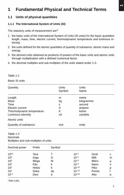
The statutory units of measurement are1)
1. the basic units of the International System of Units (Sl units) for the basic quantitieslength, mass, time, electric current, thermodynamic temperature and luminous in-tensity,
2. the units defined for the atomic quantities of quantity of substance, atomic mass andenergy,
3. the derived units obtained as products of powers of the basic units and atomic unitsthrough multiplication with a defined numerical factor,
4. the decimal multiples and sub-multiples of the units stated under 1-3.
Table 1-2DecimalsMultiples and sub-multiples of units
Decimal power Prefix Symbol
1012 Tera T 10–2 Zenti c109 Giga G 10–3 Milli m106 Mega M 10–6 Mikro µ103 Kilo k 10–9 Nano n102 Hekto h 10–12 Piko p101 Deka da 10–15 Femto f10–1 Dezi d 10–18 Atto a
Table 1-1
Basic SI units
Quantity Units UnitsSymbol Name
Length m metreMass kg kilogrammeTime s secondElectric current A ampereThermodynamic temperature K kelvinLuminous intensity cd candela
Atomic units
Quantity of substance mol mole
1)DIN 1301

2
Table 1-3
List of units
1 2 3 4 5 6 7 8
Sl unit1) Other unitsNo. Quantity Relationship1) Remarks
Name Symbol Name Symbol
1 Length, area, volume
1.1 Length metre m see Note to No. 1.1
1.2 Area square metre m2
are a 1 a = 102 m2 for land measurementhectare ha 1 ha = 104 m2 only
1.3 Volume cubic metre m3
litre l 1 l = 1 dm3 = 10–3 m3
1.4 Reciprocal reciprocal metre 1/mlength
dioptre dpt 1 dpt = 1/m
1.5 Elongation metre per m/mmetre
1) See also notes to columns 3 and 4 and to column 7 on page 15.
(continued)
Numerical value ofelongation often expressed inper cent
only for refractive index ofoptical systems

3
1
Table 1-3 (continued)
List of units
1 2 3 4 5 6 7 8
Sl unit1) Other unitsNo. Quantity Relationship1) Remarks
Name Symbol Name Symbol
2 Angle
2.1 Plane angle radian rad(angle) 1 rad = 1 m/m
full angle 1 full angle = 2 π rad
πright angle v 1 v = — rad
2
πdegree ° 1 ° = —— rad
180
minute ' 1' = 1°/60second " 1" = 1’/60
πgon gon 1 gon = —— rad
200
2.2 Solid angle steradian sr 1 sr = 1m2/m2 see DIN 1315
1) See also notes to columns 3 and 4 and to column 7 on page 15.
(continued)
see DIN 1315
In calculation the unit rad asa factor can be replaced bynumerical 1.

4
Table 1-3 (continued)
List of units
1 2 3 4 5 6 7 8
Sl unit1) Other unitsNo. Quantity Relationship1) Remarks
Name Symbol Name Symbol
3 Mass
3.1 Mass kilogramme kg
gramme g 1 g = 10–3 kgtonne t 1 t = 103 kgatomic u 1 u = 1.66053 · 10–27 kgmass unit
metric carat Kt 1 Kt = 0.2 · 10–3 kg
3.2 Mass per unit kilogramme kg/mlength per metre
Tex tex 1 tex = 10–6 kg/m = 1 g/km
1) See also notes to columns 3 and 4 and to column 7 on page 15.
(continued)
Units of weight used asterms for mass inexpressing quantities ofgoods are the units ofmass, see DIN 1305
At the present state ofmeasuring technology the3-fold standard deviation forthe relationship for u givenin col. 7 is ± 3 · 10–32 kg.
only for gems
only for textile fibres andyarns, see DIN 60905Sheet1

5
1
Table 1-3 (continued)
List of units
1 2 3 4 5 6 7 8
Sl unit1) Other unitsNo. Quantity Relationship1) Remarks
Name Symbol Name Symbol
3.3 Density kilogramme kg/m3 see DIN 1306percubic metre
3.4 Specific cubic metre m3/kg see DIN 1306volume per
kilogramme
3.5 Moment of kilogramme- kg m2
inertia square metre
1) See also notes to columns 3 and 4 and to column 7 on page 15.
(continued)
see DIN 5497 and Note to No. 3.5
6
Table 1-3 (continued)
List of units
1 2 3 4 5 6 7 8
Sl unit1) Other unitsNo. Quantity Relationship1) Remarks
Name Symbol Name Symbol
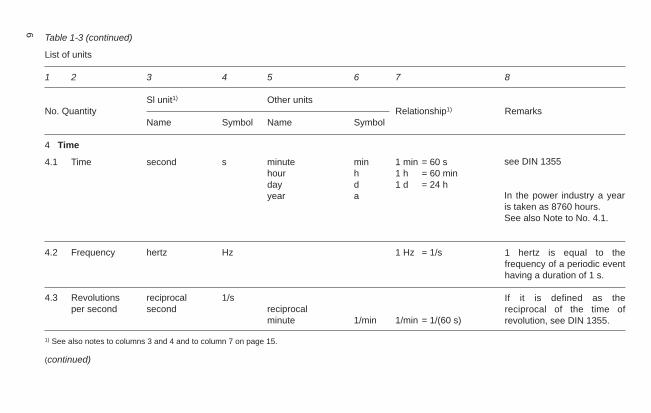
4 Time
4.1 Time second s minute min 1 min = 60 shour h 1 h = 60 minday d 1 d = 24 hyear a
4.2 Frequency hertz Hz 1 Hz = 1/s
4.3 Revolutions reciprocal 1/sper second second reciprocal
minute 1/min 1/min = 1/(60 s)
1) See also notes to columns 3 and 4 and to column 7 on page 15.
(continued)
see DIN 1355
In the power industry a yearis taken as 8760 hours.See also Note to No. 4.1.
If it is defined as thereciprocal of the time ofrevolution, see DIN 1355.
1 hertz is equal to thefrequency of a periodic eventhaving a duration of 1 s.

7
1
Table 1-3 (continued)
List of units
1 2 3 4 5 6 7 8
Sl unit1) Other unitsNo. Quantity Relationship1) Remarks
Name Symbol Name Symbol
4.4 Cyclic reciprocal 1/sfrequency second
4.5 Velocity metre per m/ssecond 1
kilometre km/h 1 km/h = —— m/sper hour 3.6
4.6 Acceleration metre per m/s2
second squared
4.7 Angular radian per rad/svelocity second
4.8 Angular radian per rad/s2
acceleration second squared
1) See also notes to columns 3 and 4 and to column 7 on page 15.
(continued)
8
Table 1-3 (continued)
List of units
1 2 3 4 5 6 7 8
Sl unit1) Other unitsNo. Quantity Relationship1) Remarks
Name Symbol Name Symbol
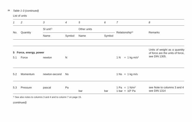
5 Force, energy, power
5.1 Force newton N 1 N = 1 kg m/s2
5.2 Momentum newton-second Ns 1 Ns = 1 kg m/s
5.3 Pressure pascal Pa 1 Pa = 1 N/m2
bar bar 1 bar = 105 Pa
1) See also notes to columns 3 and 4 and to column 7 on page 15.
(continued)
Units of weight as a quantityof force are the units of force,see DIN 1305.
see Note to columns 3 and 4see DIN 1314

9
1
Table 1-3 (continued)
List of units
1 2 3 4 5 6 7 8
Sl unit1) Other unitsNo. Quantity Relationship1) Remarks
Name Symbol Name Symbol
5.4 Mechanical newton per N/m2, Pa 1 Pa = 1 N/m2
stress square metre,pascal
5.5 Energy, work, joule J 1 J = 1 Nm = 1 Wsquantity of heat = 1 kg m2/s2
kilowatt-hour kWh 1 kWh = 3.6 MJelectron volt eV 1 eV = 1.60219 ·10–19J
5.6 Torque newton-metre Nm 1 Nm = 1 J = 1 Ws
5.7 Angular newton-second- Nsm 1 Nsm = 1 kg m2/smomentum metre
1) See also notes to columns 3 and 4 and to column 7 on page 15.
(continued)
In many technical fields it hasbeen agreed to express me-chanical stress and strengthin N/mm2.1 N/mm2 = 1 MPa.
see DIN 1345
At the present state ofmeasuring technology the3-fold standard deviation forthe relationship given in col. 7is ± 2 · 10–24 J.

10 Table 1-3 (continued)
List of units
1 2 3 4 5 6 7 8
Sl unit1) Other unitsNo. Quantity Relationship1) Remarks
Name Symbol Name Symbol
5.8 Power watt W 1 W = 1 J/s energy flow, =1 N m/sheat flow = 1 VA
6 Viscometric quantities
6.1 Dynamic pascal-second Pas 1 Pas = 1 Ns/m2 see DIN 1342viscosity = 1 kg/(sm)
6.2 Kinematic square metre m2/s see DIN 1342viscosity per second
1) See also notes to columns 3 and 4 and to column 7 on page 15.
(continued)
The watt is also termed volt-ampere (standard symbolVA) when expressing electri-cal apparent power, and Var(standard symbol var) whenexpressing electrical reactivepower, see DIN 40110.

11
1
Table 1-3 (continued)
List of units
1 2 3 4 5 6 7 8
Sl unit1) Other unitsNo. Quantity Relationship1) Remarks
Name Symbol Name Symbol
7 Temperature and heat
7.1 Temperature kelvin K
degree Celsius ° C The degree Celsius is(centigrade) the special name for
kelvin when expressingCelsius temperatures.
7.2 Thermal square metre m2/s see DIN 1341diffusivity per second
7.3 Entropy, thermal joule J/K see DIN 1345capacity per kelvin
7.4 Thermal watt per W/(K m) see DIN 1341conductivity kelvin-metre
1) See also notes to columns 3 and 4 and to column 7 on page 15. (continued)
Thermodynamic tempera-ture; see Note to No. 7.1 andDIN 1345.Kelvin is also the unit fortemperature differences andintervals.Expression of Celsius tem-peratures and Celsius tem-perature differences, seeNote to No 7.1.

12 Table 1-3 (continued)
List of units
1 2 3 4 5 6 7 8
Sl unit1) Other unitsNo. Quantity Relationship1) Remarks
Name Symbol Name Symbol
7.5 Heat transfer watt per W/(Km2) see DIN 1341coefficient kelvin-square
metre
8 Electrical and magnetic quantities
8.1 Electric current, ampere A see DIN 1324 andmagnetic potential DIN 1325difference
8.2 Electric voltage, volt V 1 V =1 W/A see DIN 1323electric potentialdifference
8 3 Electric siemens S 1 S = A/V see Note to columns 3 andconductance 4 and also DIN 1324
8.4 Electric ohm Ω 1 Ω = 1/S see DIN 1324resistance
1) See also notes to columns 3 and 4 and to column 7 on page 15. (continued)

13
1
Table 1-3 (continued)
List of units
1 2 3 4 5 6 7 8
Sl unit1) Other unitsNo. Quantity Relationship1) Remarks
Name Symbol Name Symbol
8.5 Quantity of coulomb C 1 C = 1 As see DIN 1324electricity, electric ampere-hour Ah 1 Ah = 3600 Ascharge
8.6 Electric farad F 1 F = 1 C/V see DIN 1357capacitance
8.7 Electric flux coulomb per C/m2 see DIN 1324density square metre
8.8 Electric field volt per metre V/m see DIN 1324strength
8.9 Magnetic flux weber, Wb, Vs 1 Wb = 1 Vs see DIN 1325volt-second
8.10 Magnetic flux tesla T 1 T = 1 Wb/m2 see DIN 1325density, (induction)
8.11 Inductance henry H 1 H = 1 Wb/A see DIN 1325(permeance)
1) See also notes to columns 3 and 4 and to column 7 on page 15. (continued)

14 Table 1-3 (continued)
List of units
1 2 3 4 5 6 7 8
Sl unit1) Other unitsNo. Quantity Relationship1) Remarks
Name Symbol Name Symbol
8.12 Magnetic field ampere A/m see DIN 1325intensity per metre
9 Photometric quantities
9.1 Luminous candela cdintensity
9.2 Luminance candela per cd/m2 see DIN 5031 Part 3square metre
9.3 Luminous flux lumen Im 1 Im = 1 cd · sr see DIN 5031 Part 3
9.4 Illumination lux Ix 1 lx = 1 Im/m2 see DIN 5031 Part 3
1) See also notes to columns 3 and 4 and to column 7 on page 15.
see DIN 5031 Part 3. Theword candela is stressed onthe 2nd syllable.

15
1
Notes to Table 1-3
To column 7:
A number having the last digit in bold type denotes that this number is defined byagreement (see DIN 1333).
To No. 1.1:
The nautical mile is still used for marine navigation (1 nm = 1852 m). Forconversion from inches to millimetres see DIN 4890, DIN 4892, DIN 4893.
To No. 3.5:
When converting the so-called “flywheel inertia GD2” into a mass moment ofinertia J, note that the numerical value of GD2 in kp m2 is equal to four times thenumerical value of the mass moment of inertia J in kg m2.
To No. 4.1:
Since the year is defined in different ways, the particular year in question shouldbe specified where appropriate.
3 h always denotes a time span (3 hours), but 3h a moment in time (3 o’clock).When moments in time are stated in mixed form, e.g. 2h25m3s, the abbreviationmin may be shortened to m (see DIN 1355).
To No. 7.1:
The (thermodynamic) temperature (T), also known as “absolute temperature”, isthe physical quantity on which the laws of thermodynamics are based. For thisreason, only this temperature should be used in physical equations. The unitkelvin can also be used to express temperature differences.
Celsius (centigrade) temperature (t) is the special difference between a giventhermodynamic temperature T and a temperature of T0 = 273.15 K.
Thus,
t = T – T0 = T – 273.15 K. (1)
When expressing Celsius temperatures, the standard symbol °C is to be used.
The difference ∆ t between two Celsius temperatures, e. g. the temperaturest 1 = T1 – T0 and t 2 = T2 – T0, is
∆ t = t 1 –t 2 = T1 – T2 = ∆ T (2)
A temperature difference of this nature is no longer referred to the thermo-dynamic temperature T0, and hence is not a Celsius temperature according to thedefinition of Eq. (1).
However, the difference between two Celsius temperatures may be expressedeither in kelvin or in degrees Celsius, in particular when stating a range oftemperatures, e. g. (20 ± 2) °C
Thermodynamic temperatures are often expressed as the sum of T0 and aCelsius temperature t, i. e. following Eq. (1)
T = T0 + t (3)
and so the relevant Celsius temperatures can be put in the equation straightaway. In this case the kelvin unit should also be used for the Celsius temperature(i. e. for the “special thermodynamic temperature difference”). For a Celsiustemperature of 20 °C, therefore, one should write the sum temperature as
T = T0 + t = 273.15 K + 20 K = 293.15 K (4)

16 1.1.2 Other units still in common use; metric, British and US measures
Some of the units listed below may be used for a limited transition period and in certain exceptional cases. The statutory requirements varyfrom country to country.
ångström Å length 1 Å = 0.1 nm = 10–10matmosphere physical atm pressure 1 atm = 101 325 Paatmosphere technical at, ata pressure 1 at = 98 066.5 PaBritish thermal unit Btu quantity of heat 1 Btu ≈ 1055.056 Jcalorie cal quantity of heat 1 cal = 4.1868 Jcentigon c plane angle 1 c = 1 cgon = 5 π · 10–5 raddegree deg, grd temperature difference 1 deg = 1 Kdegree fahrenheit °F temperature TK = 273.15 + (5/9) · (tF – 32)dyn dyn force 1 dyn = 10–5 Nerg erg energy 1 erg = 10–7 Jfoot ft length 1 ft = 0.3048 mgallon (UK) gal (UK) volume 1 gal (UK) ≈ 4.54609 · 10–3 m3
gallon (US) gal (US) liquid volume 1 gal (US) ≈ 3.78541 · 10–3 m3
gauss G.Gs magnetic flux density 1 G = 10–4Tgilbert Gb magnetic potential difference 1 Gb = (10/4 π) Agon g plane angle 1 g = 1 gon = 5 π · 10–3 radhorsepower hp power 1 hp ≈ 745.700 Whundredweight (long) cwt mass 1 cwt ≈ 50.8023 kginch (inches) in, " length 1 in = 25.4 mm = 254 · 10–4 minternational ampere Aint electric current 1 Aint ≈ 0.99985 Ainternational farad Fint electrical capacitance 1 Fint = (1/1.00049) Finternational henry Hint inductance 1 Hint = 1.00049 Hinternational ohm Ωint electrical resistance 1 Ωint = 1.00049 Ωinternational volt Vint electrical potential 1 Vint = 1.00034 Vinternational watt Wint power 1 Wint ≈ 1.00019 Wkilogramme-force, kilopond kp, kgf force 1 kp = 9.80665 N ≈ 10 N

17
1
Unit of mass ME mass 1 ME = 9.80665 kgmaxwell M, Mx magnetic flux 1 M = 10 nWb = 10–8 Wbmetre water column mWS pressure 1 mWS = 9806.65 PA ≈ 0,1 barmicron µ length 1 µ = 1 µm = 10–6 mmillimetres of mercury mm Hg pressure 1 mm Hg ≈ 133.322 Pamilligon cc plane angle 1 cc = 0.1 mgon = 5 π · 10–7 radoersted Oe magnetic field strength 10e = (250/π) A/mPferdestärke, cheval-vapeur PS, CV power 1 PS = 735.49875 WPfund Pfd mass 1 Pfd = 0.5 kgpieze pz pressure 1 pz = 1 mPa = 10–3 Papoise P dynamic viscosity 1 P = 0.1 Pa · spond, gram-force p, gf force 1 p = 9.80665 · 10–3 N ≈ 10 mNpound1) Ib mass 1 Ib ≈ 0.453592 kgpoundal pdl force 1 pdl ≈ 0.138255 Npoundforce Ibf force 1 Ibf ≈ 4.44822 Nsea mile, international n mile length (marine) 1 n mile = 1852 mshort hundredweight sh cwt mass 1 sh cwt ≈ 45.3592 kgstokes St kinematic viscosity 1 St = 1 cm2/s = 10–4 m2/storr Torr pressure 1 Torr ≈ 133.322 Patypographical point p length (printing) 1 p = (1.00333/2660) m ≈ 0.4 mmyard yd length 1 yd = 0.9144 mZentner z mass 1 z = 50 kg
1) UK and US pounds avoirdupois differ only after the sixth decimal place.

18 Table 1-4
Metric, British and US linear measure
Metric units of length British and US units of length
Kilometre Metre Decimetre Centimetre Millimetre Mile Yard Foot Inch Mil
km m dm cm mm mile yd ft in or " mil
1 1 000 10 000 100 000 1 000 000 0.6213 1 093.7 3 281 39 370 3 937 · 104
0.001 1 10 100 1 000 0.6213 · 10–3 1.0937 3.281 39.370 39 3700.0001 0.1 1 10 100 0.6213 · 10–4 0.1094 0.3281 3.937 3 937.00.00001 0.01 0.1 1 10 0.6213 · 10–5 0.01094 0.03281 0.3937 393.700.000001 0.001 0.01 0.1 1 0.6213 · 10–6 0.001094 0.003281 0.03937 39.371.60953 1 609.53 16 095.3 160 953 1 609 528 1 1 760 5 280 63 360 6 336 · 104
0.000914 0.9143 9.1432 91.432 914.32 0.5682 · 10–3 1 3 36 36 0000.305 · 10–3 0.30479 3.0479 30.479 304.79 0.1894 · 10–3 0.3333 1 12 12 0000.254 · 10–4 0.02539 0.25399 2.53997 25.3997 0.158 · 10–4 0.02777 0.0833 1 1 0000.254 · 10–7 0.254 · 10–4 0.254 · 10–3 0.00254 0.02539 0.158 · 10–7 0.0277· 10–3 0.0833 · 10–3 0.001 1
Special measures: 1 metric nautical mile = 1852 m 1 Brit. or US nautical mile = 1855 m1 metric land mile = 7500 m 1 micron (µ) = 1/1000 mm = 10 000 Å

19
1
Table 1-5
Metric, British and US square measure
Metric units of area British and US units of area
Square Square Square Square Square Square Square Square Square Circularkilometres metre decim. centim. millim. mile yard foot inch mils
km2 m2 dm2 cm2 mm2 sq.mile sq.yd sq.ft sq.in cir.mils
1 1 · 106 100 · 106 100 · 108 100 · 1010 0.386013 1 196 · 103 1076 · 104 1 550 · 106 197.3 · 1013
1 · 10–6 1 100 10 000 1 000 000 0.386 · 10–6 1.1959 10.764 1 550 197.3 · 107
1 · 10–8 1 · 10–2 1 100 10 000 0.386 · 10–8 0.01196 0.10764 15.50 197.3 · 105
1 · 10–10 1 · 10–4 1 · 10–2 1 100 0.386 · 10–10 0.1196 · 10–3 0.1076 · 10–2 0.1550 197.3 · 103
1 · 10–12 1 · 10–6 1 · 10–4 1 · 10–2 1 0.386 · 10–12 0.1196 · 10–5 0.1076 · 10–4 0.00155 1 9732.58999 2 589 999 259 · 106 259 · 108 259 · 1010 1 30 976 · 102 27 878 · 103 40 145 · 105 5 098 · 1012
0.8361 · 10–6 0.836130 83.6130 8 361.307 836 130.7 0.3228 · 10–6 1 9 1296 1 646 · 106
9.290 · 10–8 9.290 · 10–2 9.29034 929.034 92 903.4 0.0358 · 10–6 0.11111 1 144 183 · 106
6.452 · 10–10 6.452 · 10–4 6.452 ·10–2 6.45162 645.162 0.2396 · 10–9 0.7716 ·10–3 0.006940 1 1.27 · 106
506.7 · 10–18 506.7 · 10–12 506.7·10–10 506.7 · 10–8 506.7 · 10–6 0.196 · 10–15 0.607 · 10–9 0.00547·10–6 0.785 · 10–6 1
Special measures: 1 hectare (ha) = 100 are (a) 1 section (sq.mile) = 64 acres = 2,589 km2
1 are (a) = 100 m2 1 acre = 4840 sq.yds = 40.468 a USA1 Bad. morgen = 56 a = 1.38 acre 1 sq. pole = 30.25 sq.yds = 25.29 m2
1 Prussian morgen = 25.53 a = 0.63 acre 1 acre = 160 sq.poles = 4840 sq.yds = 40.468 a1 Württemberg morgen = 31.52 a = 0.78 acre 1 yard of land = 30 acres = 1214.05 a Brit.1 Hesse morgen = 25.0 a = 0.62 acre 1 mile of land = 640 acres = 2.589 km2
1 Tagwerk (Bavaria) = 34.07 a = 0.84 acre1 sheet of paper = 86 x 61 cm
gives 8 pieces size A4 or 16 pieces A5or 32 pieces A6

20 Table 1-6
Metric, British and US cubic measures
Metric units of volume British and US units of volume US liquid measure
Cubic Cubic Cubic Cubic Cubic Cubic Cubic Gallon Quart Pintmetre decimetre centimetre millimetre yard foot inch
m3 dm3 cm3 mm3 cu.yd cu.ft cu.in gal quart pint
1 1 000 1 000 · 103 1 000 · 106 1.3079 35.32 61 · 103 264.2 1 056.8 2 113.61 · 10–3 1 1 000 1 000 · 103 1.3079 ·10–3 0.03532 61.023 0.2642 1.0568 2.11361 · 10–6 1 · 10–3 1 1 000 1.3079 ·10–6 0.3532 · 10–4 0.061023 0.2642 · 10–3 1.0568 · 10–3 2.1136 · 10–3
1 · 10–9 1 · 10–6 1 · 10–3 1 1.3079 · 10–9 0.3532 · 10–7 0.610 · 10–4 0.2642 · 10–6 1.0568 · 10–6 2.1136 · 10–6
0.764573 764.573 764 573 764 573 ·103 1 27 46 656 202 808 1 6160.0283170 28.31701 28 317.01 28 317 013 0.037037 1 1 728 7.48224 29.92896 59.857920.1638 · 10–4 0.0163871 16.38716 16387.16 0.2143 · 10–4 0.5787 · 10–3 1 0.00433 0.01732 0.034643.785 · 10–3 3.785442 3 785.442 3 785 442 0.0049457 0.1336797 231 1 4 80.9463 · 10–3 0.9463605 946.3605 946 360.5 0.0012364 0.0334199 57.75 0.250 1 20.4732 · 10–3 0.4731802 473.1802 473 180.2 0.0006182 0.0167099 28.875 0.125 0.500 1

21
1
Table 1-7
Conversion tables
Millimetres to inches, formula: mm x 0.03937 = inch
mm 0 1 2 3 4 5 6 7 8 9
10 0.03937 0.07874 0.11811 0.15748 0.19685 0.23622 0.27559 0.31496 0.3543310 0.39370 0.43307 0.47244 0.51181 0.55118 0.59055 0.62992 0.66929 0.70866 0.7480320 0.78740 0.82677 0.86614 0.90551 0.94488 0.98425 1.02362 1.06299 1.10236 1.1417330 1.18110 1.22047 1.25984 1.29921 1.33858 1.37795 1.41732 1.45669 1.49606 1.5354340 1.57480 1.61417 1.65354 1.69291 1.73228 1.77165 1.81102 1.85039 1.88976 1.9291350 1.96850 2.00787 2.04724 2.08661 2.12598 2.16535 2.20472 2.24409 2.28346 2.32283
Inches to millimetres, formula: inches x 25.4 = mm
inch 0 1 2 3 4 5 6 7 8 9
10 25.4 50.8 76.2 101.6 127.0 152.4 177.8 203.2 228.610 254.0 279.4 304.8 330.2 355.6 381.0 406.4 431.8 457.2 482.620 508.0 533.4 558.8 584.2 609.6 635.0 660.4 685.8 711.2 736.630 762.0 787.4 812.8 838.2 863.6 889.0 914.4 939.8 965.2 990.840 1 016.0 1 041.4 1 066.8 1 092.2 1 117.6 1 143.0 1 168.4 1 193.8 1 219.2 1 244.650 1 270.0 1 295.4 1 320.8 1 246.2 1 371.6 1 397.0 1 422.4 1 447.8 1 473.2 1 498.6
1.1.3 Fundamental physical constants
General gas constant: R = 8.3166 J K–1 mol–1
is the work done by one mole of an ideal gas under constant pressure (1013 hPa) whenits temperature rises from 0 °C to 1 °C.
Avogadro’s constant: NA (Loschmidt’s number NL): NA = 6.0225 · 1023 mol–1
number of molecules of an ideal gas in one mole.When Vm = 2.2414 · 104 cm3 · mol-1: NA/Vm = 2.686 1019 cm –3.
Atomic weight of the carbon atom: 12C = 12.0000is the reference quantity for the relative atomic weights of fundamental substances.
Fractions of inch to millimetres
inch mm inch mm inch mm inch mm inch mm
¹⁄₆₄ 0.397 ⁷⁄₃₂ 5.556 ²⁷⁄₆₄ 10.716 ⁵⁄₈ 15.875 ⁵³⁄₆₄ 21.034¹⁄₃₂ 0.794 ¹⁵⁄₆₄ 5.953 ⁷⁄₁₆ 11.112 ⁴¹⁄₆₄ 16.272 ²⁷⁄₃₂ 21.431³⁄₆₄ 1.191 ¹⁄₄ 6.350 ²⁹⁄₆₄ 11.509 ²¹⁄₃₂ 16.669 ⁵⁵⁄₆₄ 21.828¹⁄₁₆ 1.587 ¹⁷⁄₆₄ 6.747 ¹⁵⁄₃₂ 11.906 ⁴³⁄₆₄ 17.066 ⁷⁄₈ 22.225⁵⁄₆₄ 1.984 ⁹⁄₃₂ 7.144 ³¹⁄₆₄ 12.303 ¹¹⁄₁₆ 17.462 ⁵⁷⁄₆₄ 22.622³⁄₃₂ 2.381 ¹⁹⁄₆₄ 7.541 ¹⁄₂ 12.700 ⁴⁵⁄₆₄ 17.859 ²⁹⁄₃₂ 23.019⁷⁄₆₄ 2.778 ⁵⁄₆ 7.937 ³³⁄₆₄ 13.097 ²³⁄₃₂ 18.256 ⁵⁹⁄₆₄ 23.416¹⁄₈ 3.175 ²¹⁄₆₄ 8.334 ¹⁷⁄₃₂ 13.494 ⁴⁷⁄₆₄ 18.653 ¹⁵⁄₁₆ 23.812⁹⁄₆₄ 3.572 ¹¹⁄₃₂ 8.731 ³⁵⁄₆₄ 13.891 ³⁄₄ 19.050 ⁶¹⁄₆₄ 24.209⁵⁄₃₂ 3.969 ²³⁄₆₄ 9.128 ⁹⁄₁₆ 14.287 ⁴⁹⁄₆₄ 19.447 ³¹⁄₃₂ 24.606¹¹⁄₆₄ 4.366 ³⁄₈ 9.525 ³⁷⁄₆₄ 14.684 ²⁵⁄₃₂ 19.844 ⁶³⁄₆₄ 25.003³⁄₁₆ 4.762 ²⁵⁄₆₄ 9.922 ¹⁹⁄₃₂ 15.081 ⁵¹⁄₆₄ 20.241 1 25.400¹³⁄₆₄ 5.159 ¹³⁄₃₂ 10.319 ³⁹⁄₆₄ 15.478 ¹³⁄₁₆ 20.637 2 50.800

22
Base of natural logarithms: e = 2.718282
Bohr’s radius: r1 = 0.529 · 10–8 cmradius of the innermost electron orbit in Bohr’s atomic model
RBoltzmann’s constant: k = —– = 1.38 · 10–23 J · K–1NA
is the mean energy gain of a molecule or atom when heated by 1 K.
Elementary charge: eo = F/NA = 1.602 · 10–19 As is the smallest possible charge a charge carrier (e.g. electron or proton) can have.
Electron-volt: eV = 1.602 · 10–19 J
Energy mass equivalent: 8.987 · 1013 J · g–1 = 1.78 · 10–27 g (MeV)–1
according to Einstein, following E = m · c2, the mathematical basis for all observedtransformation processes in sub-atomic ranges.
Faraday’s constant: F = 96 480 As · mol–1
is the quantity of current transported by one mole of univalent ions.
Field constant, electrical: εo = 0.885419 · 10–11 F · m–1.a proportionality factor relating charge density to electric field strength.
Field constant, magnetic: µ0 = 4 · π · 10–7 H · m–1
a proportionality factor relating magnetic flux density to magnetic field strength.
Gravitational constant: γ = 6.670 · 10–11 m4 · N–1 · s–4
is the attractive force in N acting between two masses each of 1 kg weight separatedby a distance of 1 m.
Velocity of light in vacuo: c = 2.99792 · 108 m · s–1
maximum possible velocity. Speed of propagation of electro-magnetic waves.
Mole volume: Vm = 22 414 cm3 · mol–1
the volume occupied by one mole of an ideal gas at 0 °C and 1013 mbar. A mole is thatquantity (mass) of a substance which is numerically equal in grammes to the molecularweight (1 mol H2 = 2 g H2)
Planck’s constant: h = 6.625 · 10–34 J · s a proportionality factor relating energy and frequency of a light quantum (photon).
Stefan Boltzmann’s radiation constant: δ = 5.6697 · 10–8 W · m–2 K–4 relates radiantenergy to the temperature of a radiant body. Radiation coefficient of a black body.
Temperature of absolute zero: T0 = –273.16 °C = 0 K.
Wave impedance of space: Γ0 = 376.73 Ωcoefficient for the H/E distribution with electromagnetic wave propagation.
Γ0 = µ0 /ε0 = µ0 · c = 1/ (ε0 · c)
Weston standard cadmium cell: E0 = 1.0186 V at 20 °C.
Wien’s displacement constant: A = 0.28978 cm · K enables the temperature of a light source to be calculated from its spectrum.

23
1
If two metals included in this table come into contact, the metal mentioned first willcorrode.
The less noble metal becomes the anode and the more noble acts as the cathode. Asa result, the less noble metal corrodes and the more noble metal is protected.
Metallic oxides are always less strongly electronegative, i. e. nobler in the electrolyticsense, than the pure metals. Electrolytic potential differences can therefore also occurbetween metal surfaces which to the engineer appear very little different. Even thoughthe potential differences for cast iron and steel, for example, with clean and rusty surfacesare small, as shown in Table 1-9, under suitable circumstances these small differencescan nevertheless give rise to significant direct currents, and hence corrosive attack.
Table 1-9
Standard potentials of different types of iron against hydrogen, in volts
SM steel, clean surface approx. – 0.40 cast iron, rusty approx. – 0.30cast iron, clean surface approx. – 0.38 SM steel, rusty approx. – 0.25
1.2.2 Faraday’s law
1. The amount m (mass) of the substances deposited or converted at an electrode isproportional to the quantity of electricity Q = l · t.
m ~ l · t
1.2 Physical, chemical and technical values
1.2.1 Electrochemical series
If different metals are joined together in a manner permitting conduction, and both arewetted by a liquid such as water, acids, etc., an electrolytic cell is formed which givesrise to corrosion. The amount of corrosion increases with the differences in potential. Ifsuch conducting joints cannot be avoided, the two metals must be insulated from eachother by protective coatings or by constructional means. In outdoor installations,therefore, aluminium/copper connectors or washers of copper-plated aluminium sheetare used to join aluminium and copper, while in dry indoor installations aluminium andcopper may be joined without the need for special protective measures.
Table 1-8
Electrochemical series, normal potentials against hydrogen, in volts.
1. Lithium approx. – 3.02 10. Zinc approx. – 0.77 19. Hydrogen approx. 0.02. Potassium approx. – 2.95 11. Chromium approx. – 0.56 20. Antimony approx. + 0.23. Barium approx. – 2.8 12. Iron approx. – 0.43 21. Bismuth approx. + 0.24. Sodium approx. – 2.72 13. Cadmium approx. – 0.42 22. Arsenic approx. + 0.35. Strontium approx. – 2.7 14. Thallium approx. – 0.34 23. Copper approx. + 0.356. Calcium approx. – 2.5 15. Cobalt approx. – 0.26 24. Silver approx. + 0.807. Magnesium approx. – 1.8 16. Nickel approx. – 0.20 25. Mercury approx. + 0.868. Aluminium approx. – 1.45 17. Tin approx. – 0.146 26. Platinum approx. + 0.879. Manganese approx. – 1.1 18. Lead approx. – 0.132 27. Gold approx. + 1.5

24
2. The amounts m (masses) of the substances converted from different electrolytes byequal quantities of electricity Q = l · t behave as their electrochemical equivalentmasses M*. The equivalent mass M* is the molar mass M divided by theelectrochemical valency n (a number). The quantities M and M* can be stated ing/mol.
M*m = — l · t
F
If during electroysis the current I is not constant, the product
l · t must be represented by the integral l dt.
The quantity of electricity per mole necessary to deposit or convert the equivalent massof 1 g/mol of a substance (both by oxidation at the anode and by reduction at thecathode) is equal in magnitude to Faraday's constant (F = 96480 As/mol).
Table 1-10
Electrochemical equivalents1)
Valency Equivalent Quantity Approximaten mass2) precipitated, optimum current
g/mol theoretical efficiencyg/Ah %
Aluminium 3 8.9935 0.33558 85 … 98Cadmium 2 56.20 2.0970 95 … 95Caustic potash 1 56.10937 2.0036 95Caustic soda 1 30.09717 1.49243 95Chlorine 1 35.453 1.32287 95Chromium 3 17.332 0.64672 —Chromium 6 8.666 0.32336 10 … 18Copper 1 63.54 2.37090 65 … 98Copper 2 31.77 1.18545 97 … 100Gold 3 65.6376 2.44884 —Hydrogen 1 1.00797 0.037610 100Iron 2 27.9235 1.04190 95 … 100Iron 3 18.6156 0.69461 —Lead 2 103.595 3.80543 95 … 100Magnesium 2 12.156 0.45358 —Nickel 2 29.355 1.09534 95 … 98Nickel 3 19.57 0.73022 —Oxygen 2 7.9997 0.29850 100Silver 1 107.870 4.02500 98 … 100Tin 2 59.345 2.21437 70 … 95Tin 4 29.6725 1.10718 70 … 95Zinc 2 32.685 1.21959 85 … 93
1) Relative to the carbon-12 isotope = 12.000.2) Chemical equivalent mass is molar mass/valency in g/mol.
Example:
Copper and iron earthing electrodes connected to each other by way of the neutralconductor form a galvanic cell with a potential difference of about 0.7 V (see Table 1-8).These cells are short-circuited via the neutral conductor. Their internal resistance is de-
t2
t1

25
1
termined by the earth resistance of the two earth electrodes. Let us say the sum of allthese resistances is 10 Ω. Thus, if the drop in “short-circuit emf” relative to the “open-circuit emf” is estimated to be 50 % approximately, a continuous corrosion current of35 mA will flow, causing the iron electrode to decompose. In a year this will give anelectrolytically active quantity of electricity of
h Ah35 mA · 8760 — = 306 —– .a a
Since the equivalent mass of bivalent iron is 27.93 g/mol, the annual loss of weight fromthe iron electrode will be
27.93 g/mol 3600 sm = ————————— · 306 Ah/a · ————— = 320 g/a.
96480 As/mol h
1.2.3 Thermoelectric series
If two wires of two different metals or semiconductors are joined together at their endsand the two junctions are exposed to different temperatures, a thermoelectric currentflows in the wire loop (Seebeck effect, thermocouple). Conversely, a temperaturedifference between the two junctions occurs if an electric current is passed through thewire loop (Peltier effect).
The thermoelectric voltage is the difference between the values, in millivolts, stated inTable 1-11. These relate to a reference wire of platinum and a temperature difference of100 K.
Table 1-11
Thermoelectric series, values in mV, for platinum as reference and temperaturedifference of 100 K
Bismut ll axis –7.7 Rhodium 0.65Bismut ⊥ axis –5.2 Silver 0.67 … 0.79Constantan –3.37 … –3.4 Copper 0.72 … 0.77Cobalt –1.99 … –1.52 Steel (V2A) 0.77Nickel –1.94 … –1.2 Zinc 0.6 … 0.79Mercury –0.07 … +0.04 Manganin 0.57 … 0.82Platinum ± 0 Irdium 0.65 … 0.68Graphite 0.22 Gold 0.56 … 0.8Carbon 0.25 … 0.30 Cadmium 0.85 … 0.92Tantalum 0.34 … 0.51 Molybdenum 1.16 … 1.31Tin 0.4 … 0.44 Iron 1.87 … 1.89Lead 0.41 … 0.46 Chrome nickel 2.2Magnesium 0.4 … 0.43 Antimony 4.7 … 4.86Aluminium 0.37 … 0.41 Silicon 44.8Tungsten 0.65 … 0.9 Tellurium 50Common thermocouplesCopper/constantan Nickel chromium/nickel(Cu/const) up to 500 °C (NiCr/Ni) up to 1 000 °CIron/constantan Platinum rhodium/(Fe/const) up to 700 °C platinum up to 1 600 °CNickel chromium/ Platinum rhodium/constantan up to 800 °C platinum rhodium up to 1 800 °C

26
1.2.4 pH value
The pH value is a measure of the “acidity” of aqueous solutions. It is defined as thelogarithm to base 10 of the reciprocal of the hydrogen ion concentration CH3O1).
pH ≡ –log CH3O.
pH scale1 m = 1 mol/ l hydrochloric acid (3.6 % HCl —– 0
0.1 m hydrochloric acid (0.36 % HCl)—–—–—–—–—–—–—–gastric acid—–—–—–—–—–—–—– —– 1
—– 2vinegar ( ≈ 5 % CH3 COOH)—–—–—–—–—–—–—–
—– 3
acidmarsh water—–—–—–—–—–—–—– —– 4
—– 5
—– 6
river water—–—–—–—–—–—–—– —– 7
tap water 20 Ωm—–—–—–—–—–—–—– neutral
—– 8see water 0.15 Ωm (4 % NaCl)—–—–—–—–—–—–—–—– 9
—– 10
0.1 m ammonia water (0.17 % NH3)—–—–—–—–—–—–—– —– 11alkaline
saturated lime-water (0.17 % CaOH2)—–—–—–—–—–—–—– —– 12
0.1 m caustic soda solution (0.4 % NaOH)—–—–—–—–—–—–—– —– 13
Fig. 1-1
pH value of some solutions1) CH3O = Hydrogen ion concentration in mol/l.
1.2.5 Heat transfer
Heat content (enthalpy) of a body: Q = V · ρ · c · ∆ϑV volume, ρ density, c specific heat, ∆ϑ temperature difference
Heat flow is equal to enthalpy per unit time: Φ = Q/t
Heat flow is therefore measured in watts (1 W = 1 J/s).
27
1
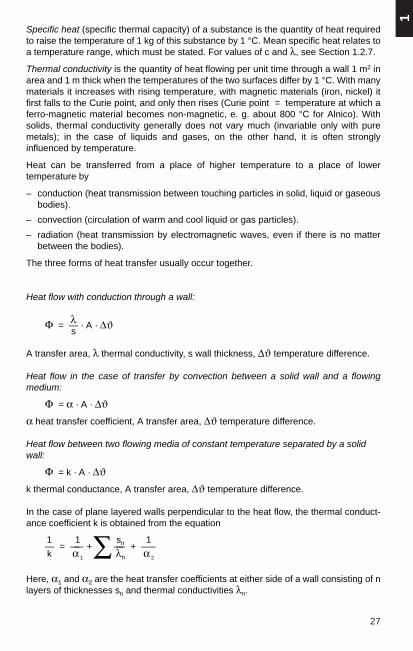
Specific heat (specific thermal capacity) of a substance is the quantity of heat requiredto raise the temperature of 1 kg of this substance by 1 °C. Mean specific heat relates toa temperature range, which must be stated. For values of c and λ, see Section 1.2.7.
Thermal conductivity is the quantity of heat flowing per unit time through a wall 1 m2 inarea and 1 m thick when the temperatures of the two surfaces differ by 1 °C. With manymaterials it increases with rising temperature, with magnetic materials (iron, nickel) itfirst falls to the Curie point, and only then rises (Curie point = temperature at which aferro-magnetic material becomes non-magnetic, e. g. about 800 °C for Alnico). Withsolids, thermal conductivity generally does not vary much (invariable only with puremetals); in the case of liquids and gases, on the other hand, it is often stronglyinfluenced by temperature.
Heat can be transferred from a place of higher temperature to a place of lowertemperature by
– conduction (heat transmission between touching particles in solid, liquid or gaseousbodies).
– convection (circulation of warm and cool liquid or gas particles).
– radiation (heat transmission by electromagnetic waves, even if there is no matterbetween the bodies).
The three forms of heat transfer usually occur together.
Heat flow with conduction through a wall:
λΦ = — · A · ∆ϑs
A transfer area, λ thermal conductivity, s wall thickness, ∆ϑ temperature difference.
Heat flow in the case of transfer by convection between a solid wall and a flowingmedium:
Φ = α · A · ∆ϑα heat transfer coefficient, A transfer area, ∆ϑ temperature difference.
Heat flow between two flowing media of constant temperature separated by a solidwall:
Φ = k · A · ∆ϑk thermal conductance, A transfer area, ∆ϑ temperature difference.
In the case of plane layered walls perpendicular to the heat flow, the thermal conduct-ance coefficient k is obtained from the equation
1 1 sn 1— = —— + —— + –—k α 1
∑ λn α 2
Here, α1 and α2 are the heat transfer coefficients at either side of a wall consisting of nlayers of thicknesses sn and thermal conductivities λn.

28
Thermal radiation
For two parallel black surfaces of equal size the heat flow exchanged by radiation is
Φ12 = σ · A(T14 – T2
4)
With grey radiating surfaces having emissivities of ε1 and ε2, it is
Φ12 = C12 · A (T14 – T2
4)
σ = 5.6697 · 10–8 W · m–2 · K–4 radiation coefficient of a black body (Stefan Boltzmann’sconstant), A radiating area, T absolute temperature.
Index 1 refers to the radiating surface, Index 2 to the radiated surface.
C12 is the effective radiation transfer coefficient. It is determined by the geometry andemissivity ε of the surface.
Special cases: A1 A2 C12 = σ · ε1
σA1 ≈ A2 C12 = —————
1 1– + – – 1ε1 ε2
Table 1-12
Emissivity ε (average values ϑ < 200 °C)
Black body 1 Oil 0.82Aluminium, bright 0.04 Paper 0.85Aluminium, oxidized 0.5 Porcelain, glazed 0.92Copper, bright 0.05 Ice 0.96Copper, oxidized 0.6 Wood (beech) 0.92Brass, bright 0.05 Roofing felt 0.93Brass, dull 0.22 Paints 0.8-0.95Steel, dull, oxidized 0.8 Red lead oxide 0.9Steel, polished 0.06 Soot 0.94
σA2 includes A1 C12 = ————————
1 A1 1– + — · — – 1ε1 A2 (ε2 )

29
1
Table 1-13
Heat transfer coefficients α in W/(m2 · K) (average values)
Natural air movement in a closed spaceWall surfaces 10Floors, ceilings: in upward direction 7
in downward direction 5Force-circulated airMean air velocity w = 2 m/s 20Mean air velocity w > 5 m/s 6.4 · w0.75
1.2.6 Acoustics, noise measurement, noise abatement
Perceived sound comprises the mechanical oscillations and waves of an elastic mediumin the frequency range of the human ear of between 16 Hz and 20 000 Hz. Oscillationsbelow 16 Hz are termed infrasound and above 20 000 Hz ultrasound. Sound waves canoccur not only in air but also in liquids (water-borne sound) and in solid bodies (solid-borne sound). Solid-borne sound is partly converted into audible air-borne sound at thebounding surfaces of the oscillating body. The frequency of oscillation determines thepitch of the sound. The sound generally propagates spherically from the sound source,as longitudinal waves in gases and liquids and as longitudinal and transverse waves insolids.
Sound propagation gives rise to an alternating pressure, the root-mean-square value ofwhich is termed the sound pressure p. It decreases approximately as the square of thedistance from the sound source. The sound power P is the sound energy flowingthrough an area in unit time. Its unit of measurement is the watt.
Since the sensitivity of the human ear is proportional to the logarithm of the soundpressure, a logarithmic scale is used to represent the sound pressure level asloudness.
The sound pressure level L is measured with a sound level metre as the logarithm ofthe ratio of sound pressure to the reference pressure po, see DIN 35 632
pL = 20 lg — in dB.po
Here: po reference pressure, roughly the audible threshold at 1000 Hz.
po = 2 · 10–5 N/m2 = 2 · 10–4 µbar
p = the root-mean-square sound pressure
Example:
p = 2 · 10–3 N/m2 measured with a sound level metre, then
2 · 10–3sound level L = 20 lg ———— = 40 dB.
2 · 10–5
The loudness of a sound can be measured as DIN loudness (DIN 5045) or as theweighted sound pressure level. DIN loudness (λ DIN) is expressed in units of DIN phon.

30
The weighted sound pressure levels LA, LB, LC, which are obtained by switching indefined weighting networks A, B, C in the sound level metre, are stated in the unit dB(decibel). The letters A, B and C must be added to the units in order to distinguish thedifferent values, e. g. dB (A). According to an ISO proposal, the weighted soundpressure LA in dB (A) is recommended for expressing the loudness of machinery noise.DIN loudness and the weighted sound pressure level, e.g. as recommended in IECpublication 123, are related as follows: for all numerical values above 60 the DINloudness in DIN phon corresponds to the sound pressure level LB in dB (B), for allnumerical values between 30 and 60 to the sound pressure level LA in dB (A). All noiselevel values are referred to a sound pressure of 2 · 10–5 N/m2.
According to VDI guideline 2058, the acceptable loudness of noises must on averagenot exceed the following values at the point of origin:
Area Daytime Night-time(6–22 hrs) (22–6 hrs)
dB (A) dB (A)
Industrial 70 70Commercial 65 50Composite 60 45Generally residential 55 40Purely residential 50 35Therapy (hospitals, etc.) 45 35
Short-lived, isolated noise peaks can be disregarded.
Disturbing noise is propagated as air- and solid-borne sound. When these sound wavesstrike a wall, some is thrown back by reflection and some is absorbed by the wall. Air-borne noise striking a wall causes it to vibrate and so the sound is transmitted into theadjacent space. Solid-borne sound is converted into audible air-borne sound byradiation from the bounding surfaces. Ducts, air-shafts, piping systems and the like cantransmit sound waves to other rooms. Special attention must therefore be paid to thisat the design stage.
There is a logarithmic relationship between the sound pressure of several soundsources and their total loudness.
Total loudness of several sound sources:
A doubling of equally loud sound sources raises the sound level by 3 dB (example: 3 sound sources of 85 dB produce 88 dB together). Several sound sources of differentloudness produce together roughly the loudness of the loudest sound source.(Example: 2 sound sources of 80 and 86 dB have a total loudness of 87 dB). Inconsequence: with 2 equally loud sound sources attenuate both of them, with soundsources of different loudness attentuate only the louder.
An increase in leveI of 10 dB signifies a doubling, a reduction of 10 dB a halving of theperceived loudness.

31
1
In general, noises must be kept as low as possible at their point of origin. This can oftenbe achieved by enclosing the noise sources.
Sound can be reduced by natural means. The most commonly used sound-absorbentmaterials are porous substances, plastics, cork, glass fibre and mineral wool, etc. Themain aim should be to reduce the higher-frequency noise components. This is alsogenerally easier to achieve than eliminating the lower-frequency noise.
When testing walls and ceilings for their behaviour regarding air-borne sound, onedetermines the difference “D” in sound level “L” for the frequency range from 100 Hz to3200 Hz.
pD = L1 – L2 in dB where L = 20 lg — dBpo
L1 = sound level in room containing sound source
L2 = sound level in room receiving the sound
Table 1-14
Attenuation figures for some building materials in the range 100 to 3200 Hz
Structural Attenuation Structural Attenuationcomponent dB component dB
Brickwork rendered, Single door without 12 cm thick 45 extra sealing to 20Brickwork rendered, Single door with 25 cm thick 50 good seal 30Concrete wall, 10 cm thick 42 Double door without seal 30Concrete wall, 20 cm thick 48 Double door with extra
sealing 40Wood wool mat, 8 cm thick 50 Single window without
sealing 15Straw mat, 5 cm thick 38 Spaced double window
with seal 30
The reduction in level ∆L obtainable in a room by means of sound-absorbing materialsor structures is:
A2 T1∆L = 10 lg — = 10 lg — dBA1 T2
In the formula:
VA = 0.163 – in m2
T
V = volume of room in m3
T = reverberation time in s in which the sound level L falls by 60 dB after soundemission ceases.
Index 1 relates to the state of the untreated room, Index 2 to a room treated with noise-reduction measures.

32 1.2.7 Technical values of solids, liquids and gases
Table 1-15
Technical values of solids
Material Density Melting Boiling Linear Thermal Mean Specific Temperatureρ or point thermal conducti- spec. electrical coefficient α
freezing expansion vity λ at heat c at resistance ρ of electricalpoint α 20 °C 0 . .100 °C at 20 °C resistance
mm/K at 20 °Ckg/dm3 °C °C x 10–6 1) W/(m · K) J/(kg · K) Ω mm2/m 1/K
E-aluminium F9 2.70 658 2270 23.8 220 920 0.02874 0.0042Alu alloy AlMgSi 1 F20 2.70 ≈ 645 23 190 920 0.0407 0.0036Lead 11.34 327 1730 28 34 130 0.21 0.0043
Bronze CuSnPb 8.6 . .9 ≈ 900 ≈ 17.5 42 360 ≈ 0.027 0.004Cadmium 8.64 321 767 31.6 92 234 0.762 0.0042Chromium 6.92 1800 2 400 8.5 452 0.028
Iron, pure 7.88 1530 2 500 12.3 71 464 0.10 0.0058Iron, steel ≈ 7.8 ≈ 1350 ≈ 11.5 46 485 0.25. .0.10 ≈ 0.005Iron, cast ≈ 7.25 ≈ 1200 ≈ 11 46 540 0.6. .1 0.0045
Gold 19.29 1063 2 700 14.2 309 130 0.022 0 0038Constantan Cu + Ni 8 . .8.9 1600 16.8 22 410 0.48 . .0.50 ≈ 0.00005Carbon diamond 3.51 ≈ 3 600 4 200 1.3 502Carbon graphite 2.25 7.86 5 711
E-copper F30 8.92 1083 2 330 16.5 385 393 0.01786 0.00392E-copper F20 8.92 1083 2 330 16.5 385 393 0.01754 0.00392Magnesium 1.74 650 1110 25.0 167 1034 0.0455 0.004
1) between 0 °C and 100 °C (continued)

33
1
Table 1-15 (continued)
Technical values of solids
Material Density Melting Boiling Linear Thermal Mean Specific Temperatureρ or point thermal conducti- spec. electrical coefficient α
freezing expansion vity λ at heat c at resistance ρ of electricalpoint α 20 °C 0. .100 °C at 20 °C resistance
mm/K at 20 °Ckg/dm3 °C °C x 10–6 1) W/(m · K) J/(kg · K) Ω mm2/m 1/K
Brass (Ms 58) 8.5 912 17 110 397 ≈ 0.0555 0.0024Nickel 8.9 1455 3 000 13 83 452 ≈ 0.12 0.0046Platinum 21.45 1773 3 800 8.99 71 134 ≈ 0.11 0.0039
Mercury 13.546 38.83 357 61 8.3 139 0.698 0.0008Sulphur (rhombic) 2.07 113 445 90 0.2 720Selenium (metallic) 4.26 220 688 66 351
Silver 10.50 960 1950 19.5 421 233 0.0165 0.0036Tungsten 19.3 3 380 6 000 4.50 167 134 0.06 0.0046Zinc 7.23 419 907 16.50 121 387 0.0645 0.0037Tin 7.28 232 2 300 26.7 67 230 0.119 0.004
1) between 0 °C and 100 °C

34
Table 1-16
Technical values of liquids
Material Chemical Density Melting Boiling Expansion Thermal Specific Relativeformula ρ or point at coefficient conductivity heat c p dielectric
freezing 760 Torr x 10–3 λ at 20 °C at 0 °C constant εr
point at 180 °Ckg/dm3 °C °C at 18 °C W/(m · K) J/(kg · K)
Acetone C3H6O 0.791 — 95 56.3 1.43 2 160 21.5Ethyl alcohol C2H6O 0.789 — 114 78.0 1.10 0.2 2 554 25.8Ethyl ether C4H10O 0.713 — 124 35.0 1.62 0.14 2 328 4.3
Ammonia NH3 0.771 — 77.8 — 33.5 0.022 4 187 14.9Aniline C6H7N 1.022 — 6.2 184.4 0.84 2 064 7.0Benzole C6H6 0.879 + 5.5 80.1 1.16 0.14 1 758 2.24
Acetic acid C2H4O2 1.049 + 16.65 117.8 1.07 2 030 6.29Glycerine C3H8O3 1.26 — 20 290 0.50 0.29 2 428 56.2Linseed oil 0.94 — 20 316 0.15 2.2
Methyl alcohol CH4O 0.793 — 97.1 64.7 1.19 0.21 2 595 31.2Petroleum 0.80 0.99 0.16 2 093 2.1Castor oil 0.97 0.69 1 926 4.6
Sulphuric acid H2S O4 1.834 — 10.5 338 0.57 0.46 1 385 > 84Turpentine C10H16 0.855 — 10 161 9.7 0.1 1 800 2.3Water H2O 1.001) 0 106 0.18 0.58 4 187 88
1) at 4 °C

35
1
Table 1- 17
Technical values of gases
Material Chemical Density Melting Boiling Thermal Specific Relative1)
formula ρ1) point point conductivity λ heat cp at 0 °C dielectricconstant εr
kg/m3 °C °C 10–2 W/(m · K) J/(kg · K)
Ammonia NH3 0.771 — 77.7 — 33.4 2.17 2 060 1.0072Ethylene C2H4 1.260 — 169.4 — 103.5 1.67 1 611 1.001456Argon Ar 1.784 — 189.3 — 185.9 1.75 523 1.00056
Acetylene C2H2 1.171 — 81 — 83.6 1.84 1 511Butane C4H10 2.703 — 135 — 0.5 0.15Chlorine Cl2 3.220 — 109 — 35.0 0.08 502 1.97
Helium He 0.178 — 272 — 268.9 1.51 5 233 1.000074Carbon monoxide CO 1.250 — 205 — 191.5 0.22 1 042 1.0007Carbon dioxide CO2 1.977 — 56 — 78.5 1.42 819 1.00095
Krypton Kr 3.743 — 157.2 — 153.2 0.88Air CO2 free 1.293 — 194.0 2.41 1 004 1.000576Methane CH4 0.717 — 182.5 — 161.7 3.3 2 160 1.000953
Neon Ne 0.8999 — 248.6 — 246.1 4.6Ozone O3 2.22 — 252 — 112Propane C2H8 2.019 — 189.9 — 42.6
Oxygen O2 1.429 — 218.83 — 192.97 2.46 1 038 1.000547Sulphur hexafluoride SF6 6.072) — 50.83) — 63 1.282) 670 1.00212)
Nitrogen N2 1.250 — 210 — 195.81 2.38 1042 1.000606Hydrogen H2 0.0898 — 259.2 — 252.78 17.54 14 235 1.000264
1) at 0 °C and 1013 mbar2) at 20 °C and 1013 mbar 3) at 2.26 bar

36
1.3 Strength of materials
1.3.1 Fundamentals and definitions
External forces F acting on a cross-section A of a structural element can give rise totensile stresses (σz), compressive stresses (σd), bending stresses (σb), shear stresses(τs) or torsional stresses (τt). If a number of stresses are applied simultaneously to acomponent, i. e. compound stresses, this component must be designed according tothe formulae for compound strength. In this case the following rule must be observed:
Normal stresses σz. σd. σb,Tangential stresses (shear and torsional stresses) τs, τt.
are to be added arithmetically;
Normal stresses σb with shear stresses τs,Normal stresses σb with torsional stresses τt,
are to be added geometrically.
Fig. 1-2
Stress-strain diagram, a) Tensile test with pronounced yield point, material = structuralsteel; b) Tensile test without pronounced yield point, material = Cu/Al, ε Elongation,σ Tensile stress, σs Stress at yield point, σE Stress at proportionality limit, Rp02 Stresswith permanent elongation less than 0.2 %, σB Breaking stress.
Elongation ε = ∆ l/l0 (or compression in the case of the compression test) is foundfrom the measured length l0 of a bar test specimen and its change in length ∆ l = l – l0
in relation to the tensile stress σz, applied by an external force F. With stresses belowthe proportionality limit σE elongation increases in direct proportion to the stress σ(Hooke’s law).
Stress σ σEThe ratio ———————— = —– = E is termed the elasticity modulus.Elongation ε εE
E is an imagined stress serving as a measure of the resistance of a material to deforma-tion due to tensile or compressive stresses; it is valid only for the elastic region.
According to DIN 1602/2 and DIN 50143, E is determined in terms of the load σ0.01, i.e.the stress at which the permanent elongation is 0.01 % of the measured length of thetest specimen.
a) b)
E
37
1
If the stresses exceed the yield point σs, materials such as steel undergo permanentelongation. The ultimate strength, or breaking stress, is denoted by σB, although a bardoes not break until the stress is again being reduced. Breaking stress σB is related tothe elongation on fracture δ of a test bar. Materials having no marked proportional limitor elastic limit, such as copper and aluminium, are defined in terms of the so-calledRp0.2-limit, which is that stress at which the permanent elongation is 0.2 % after theexternal force has been withdrawn, cf. DIN 50144.
For reasons of safety, the maximum permissible stresses, σmax or τmax in the materialmust be below the proportional limit so that no permanent deformation, such aselongation or deflection, persists in the structural component after the external forceceases to be applied.
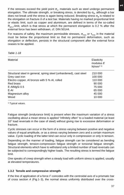
Table 1-18
Material Elasticitymodulus EN/mm2 1)
Structural steel in general, spring steel (unhardened), cast steel 210 000Grey cast iron 100 000Electro copper, Al bronze with 5 % Al, rolled 110 000Red brass 90 000E-AlMgSi 0.5 75 000E-AI 65 000Magnesium alloy 45 000Wood 10 000
1) Typical values.
Fatigue strength (endurance limit) is present when the maximum variation of a stressoscillating about a mean stress is applied “infinitely often” to a loaded material (at least107 load reversals in the case of steel) without giving rise to excessive deformation orfracture.
Cyclic stresses can occur in the form of a stress varying between positive and negativevalues of equal amplitude, or as a stress varying between zero and a certain maximumvalue. Cyclic loading of the latter kind can occur only in compression or only in tension.
Depending on the manner of loading, fatigue strength can be considered as bendingfatigue strength, tension-compression fatigue strength or torsional fatigue strength.Structural elements which have to withstand only a limited number of load reversals canbe subjected to correspondingly higher loads. The resulting stress is termed the fatiguelimit.
One speaks of creep strength when a steady load with uniform stress is applied, usuallyat elevated temperatures.
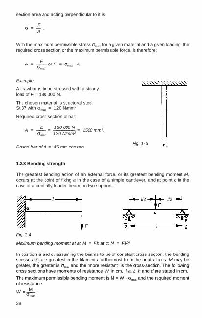
1.3.2 Tensile and compressive strength
If the line of application of a force F coincides with the centroidal axis of a prismatic barof cross section A (Fig.1-3), the normal stress uniformly distributed over the cross-
38
section area and acting perpendicular to it is
Fσ = — .A
With the maximum permissible stress σmax for a given material and a given loading, therequired cross section or the maximum permissible force, is therefore:
FA = ——— or F = σmax · A.σmax
Example:
A drawbar is to be stressed with a steadyload of F = 180 000 N.
The chosen material is structural steel St 37 with σmax = 120 N/mm2.
Required cross section of bar:
E 180 000 NA = ——— = ———————— = 1500 mm2.σmax 120 N/mm2
Round bar of d = 45 mm chosen.
1.3.3 Bending strength
The greatest bending action of an external force, or its greatest bending moment M,occurs at the point of fixing a in the case of a simple cantilever, and at point c in thecase of a centrally loaded beam on two supports.
Fig. 1-4
Maximum bending moment at a: M = Fl; at c: M = Fl/4
In position a and c, assuming the beams to be of constant cross section, the bendingstresses σb are greatest in the filaments furthermost from the neutral axis. M may begreater, the greater is σmax and the “more resistant” is the cross-section. The followingcross sections have moments of resistance W in cm, if a, b, h and d are stated in cm.
The maximum permissible bending moment is M = W · σmax and the required momentof resistance
MW = —–— .σmax
Fig. 1-3
l
F
l/2 l/2
l

39
1
Example:
A mild-steel stud (σmax = 70 N/mm2) with an unsupported length of
l = 60 mm is to be loaded in the middle with a force F = 30 000 N. Required moment ofresistance is:
M F · l 30 000 N · 60 mmW = ————— = ————— = ——————————— = 6.4 · 103 mm3.σmax 4 · σmax 4 · 70 N/mm2
According to Table 1-22, the moment of resistance W with bending is W ≈ 0.1 · d 3.
The diameter of the stud will be: d = 310 W, d =
364 000 =
364 · 10 = 40 mm.
1.3.4 Loadings on beams
Table 1-19
Bending load
Case Reaction force Required DeflectionBending moment ofmoment resistance, max.
permissible load
F l F l3A = F W = ——— f = ——— σmax 3 E J
σmax WMmax = F l F = ———— —
l
Q l Q l3A = Q W = ———— f = ———
2 σmax 8 E J
Q l 2 σmax WMmax = —— Q = ————— —
2 l
F F l F l3A = B = — W = ——— f = ————
2 4 σmax 48 E J
F l 4 σmax WMmax = —— F = ————— —
4 l
Q Q l 5 Q l3A = B = — W = ———— f = —— · ——
2 8 σmax 384 E J
Q l 8 σmax WMmax = —— Q = ————— —
8 l(continued)
l
l
l
l

40
Table 1-19 (continued)
Bending load
Case Reaction force Required DeflectionBending moment ofmoment resistance, max.
permissible load
F b F a b F a 2 b 2A = —— W = ———— f = —————
l l σmax 3 E J l
F a σmax W lB = —— F = —————
l a b
Mmax = A a = B b
for F1 = F2 = F 1) F a F aW = ——— f = ————
A = B = F σmax 24 E J[3 (l + 2 a) 2 – 4 a2]
σmax WMmax = F a F = ————
a
F1 e + F2 c A a F1 a2 e2+ F2l2 d2
A = ——————— W1= ——— f = —————————l σmax 3 E J l
F1 a + F2 d B cB = ——————— W2= ———
l σmax
Determine beam forgreatest “W”
A and B = Section at risk.
F = Single point load, Q = Uniformly distributed load. 1) If F1 und F2 are not equal, calculate with the third diagram.
Q Q l Q l3A = B = — W = ———— f = —— — · ——
l 12 σzul E J 384
Q l 12 σzul WMmax = —— Q = ——————
12 l
l
l
l
l

41
1
1.3.5 Buckling strength
Thin bars loaded in compression are liable to buckle. Such bars must be checked bothfor compression and for buckling strength, cf. DIN 4114.
Buckling strength is calculated with Euler's formula, a distinction being drawn betweenfour cases.
Table 1-20
Buckling
Case I
One end fixed, other end free
Case II
Both ends free to move along bar axis
Case III
One end fixed, other end free to movealong bar axis
Case IV
Both ends fixed, movement alongbar axis
E = Elasticity modulus of material s = Factor of safety:J = Minimum axial moment of inertia for cast iron = 8,F = Maximum permissible force for mild carbon steel = 5,I = Length of bar for wood = 10.
l l
l l
10 E JF = ————
4 s l2
4 s F l2J = ————
10 E
40 E JF = ————
s l2
s F l2J = ————
40 E
20 E JF = ————
s l2
s F l2J = ————
20 E
10 E JF = ————
s l2
s F l2J = ————
10 E

42
1.3.6 Maximum permissible buckling and tensile stress for tubular rods
Threaded steel tube (gas pipe) DIN 2440, Table 11)
or seamless steel tube DIN 24482).
10 E 10 E D4 – d4 D 4 – d 4
Fbuck = ——— · J = ——— · ————— where J ≈ ———— from Table 1-22s l2 s l2 20 20
Ften = A · σmax
in which F ForceE Elasticity modulus = 210 000 N/mm2
J Moment of inertia in cm4
s Factor of safety = 5σmax Max. permissible stressA Cross-section areaD Outside diameterd Inside diameterl Length
Fig. 1-5
Table 1-21
Nomi- Dimensions Cross- Moment Weight Fbuck for tube length l ≈ Ften
nal dia- sec- of ofmeter tions inertia tube
D D a A J 0.5 m 1 m 1.5 m 2 m 2.5 m 3 minch mm mm mm2 cm4 kg/m N N N N N N N
10 ³⁄₈ 17.2 2.35 109.6 0.32 0.85 5400 1350 600 340 220 150 660015 ¹⁄₂ 21.3 2.65 155.3 0.70 1.22 11800 2950 1310 740 470 330 930020 ³⁄₄ 26.9 2.65 201.9 1.53 1.58 25700 6420 2850 1610 1030 710 12100
25 1 33.7 3.25 310.9 3.71 2.44 62300 15600 6920 3900 2490 1730 186500.8 25 2 144.5 0.98 1.13 16500 4100 1830 1030 660 460 173500.104 31.8 2.6 238.5 2.61 1.88 43900 11000 4880 2740 1760 1220 28600
1) No test values specified for steel ST 00.2) σmax = 350 N/mm2 for steel ST 35 DIN 1629 seamless steel tube, cf. max. permissible buckling stress
for structural steel, DIN 1050 Table 3.

43
1
1.3.7 Shear strength1)
Two equal and opposite forces F acting perpendicular to the axis of a bar stress thissection of the bar in shear. The stress is
Fτs = – or for given values of F and τs max, the required cross section isA
FA = –——–τs max
Fig. 1-6
Pull-rod coupling
Stresses in shear are always combined with a bending stress, and therefore thebending stress σb has to be calculated subsequently in accordance with the followingexample.
Rivets, short bolts and the like need only be calculated for shear stress.
Example:
Calculate the cross section of a shackle pin of structural steel ST 50-12), with Rp 0.2 min = 300 N/mm2 and τs max = 0.8 Rp 0.2 min, for the pull-rod coupling shown in Fig. 1-6.
1. Calculation for shear force:
F 150 000 NA = ———— = ————————————— = 312 mm2
2 τs max 2 · (0.8 · 300) N/mm2
yields a pin diameter of d ≈ 20 mm, with W = 0.8 · 103 mm3 (from W ≈ 0.1 · d 3, seeTable 1-22).
1) For maximum permissible stresses on steel structural components of transmission towers andstructures for outdoor switchgear installations, see VDE 0210.
2) Yield point of steel ST 50-1 σ0.2 min = 300 N/mm2, DIN 17100 Table 1 (Fe 50-1).
F = 15 000 kp ≈ 1.5 · 105 N
44
2. Verification of bending stress:
The bending moment for the pin if F l/4 with a singlepoint load, and F l/8 for a uniformly distributed load. The average value is
F l F l—— + ——
4 8 3Mb = ———————— = — F l
2 16
when F = 1.5 · 105 N, l = 75 mm becomes:
3Mb = —— · 1.5 · 105 N · 75 mm ≈ 21 · 105 N · mm;
16
Mb 21 · 105 N · mm N NσB = –— = —————————— ≈ 262 · 103 ——— = 2.6 · 105 ———W 0.8 · 103 mm3 mm2 mm2
i. e. a pin calculated in terms of shear with d = 20 mm will be too weak. The requiredpin diameter d calculated in terms of bending is
Mb 21 · 105 N · mmW= ———= —————————— = 7 · 103 mm2 = 0.7 cm3
σmax 300 N/mm2
d ≈ 310 · W =
310 · 7 · 103 mm3 =
370 = 41.4 mm ≈ 42 mm.
i. e. in view of the bending stress, the pin must have a diameter of 42 mm instead of20 mm.

45
1
1.3.8 Moments of resistance and moments of inertia
Table 1-22
Cross- Moment of resistance Moment of inertiasection torsion bending1) polar1) axial2)
W 4) W 4) Jp Jcm3 cm3 cm4 cm4
0.196 d 3 0.098 d 3 0.098 d 4 0.049 d 4
≈ 0.2 d 3 ≈ 0.1 d 3 ≈ 0.1 d 4 ≈ 0.05 d 4
D 4 – d 4 D 4 – d 4 0.098 (D 4– d 4) 0.049 (D 4 – d 4)0.196 ———— 0.098 ————
D D ≈ D 4 – d 4————
20
0.208 a3 0.018 a3 0.167 a 4 0.083 a 4
0.208 k b 2 h 3) b h 2 b h b h 3—— = 0.167 b h 2 —— (b 2 + h 2) —— = 0.083 b h 36 12 12
B H 3 – b h 3 B H 3 – b h 3——————— ———————
6 H 12
B H 3 – b h 3 B H 3 – b h 3——————— ———————
6 H 12
B H 3 – b h 3 B H 3 – b h 3——————— ———————
6 H 12
b h 3 + bo h o3 b h 3 + bo h o
3——————— ———————
6 h 12
1) Referred to CG of area.2) Referred to plotted axis.3) Values for k: if h : b = 1 1.5 2 3 4
——————————————————————————then k = 1 1.11 1.18 1.27 1.36
4) Symbol Z is also applicable, see DIN VDE 0103

46
1.4 Geometry, calculation of areas and solid bodies
1.4.1 Area of polygons
Regular polygons (n angles)The area A, length of sides S and radii of the outerand inner circles can be taken from Table 1-23 below.
Irregular polygons
g1 h1 g 2 h 2A = ——— + ——— + …2 2
1= – (g1 h1 + g 2 h 2 + …)
2
Pythagoras theorem
c 2 = a 2 + b 2; c = a 2 + b 2
a 2 = c 2 – b 2; a = c 2 – b 2
b 2 = c 2 – a 2; b = c 2 – a 2
Table 1-23
Num- Area A Side S Outer radius Inner radiusber ofsides R rn S2 × R 2 × r 2 × R × r × S × r × R × S ×
3 0.4330 1.2990 5.1962 1.7321 3.4641 0.5774 2.0000 0.5000 0.28874 1.0000 2.0000 4.0000 1.4142 2.0000 0.7071 1.4142 0.7071 0.50005 1.7205 2.3776 3.6327 1.1756 1.4531 0.8507 1.2361 0.8090 0.68826 2.5981 2.5981 3.4641 1.0000 1.1547 1.0000 1.1547 0.8660 0.86608 4.8284 2.8284 3.3137 0.7654 0.8284 1.3066 1.0824 0.9239 1.2071
10 7.6942 2.9389 3.2492 0.6180 0.6498 1.6180 1.0515 0.9511 1.538812 11.196 3.0000 3.2154 0.5176 0.5359 1.9319 1.0353 0.9659 1.8660

1Triangle A = – a h U = a + b + c
2 1e = – h3
a + bTrapezium A = ——— · h U = a + b + c + d
2 h a + 2 be = – · ————
3 a + b
Rectangle A = a b U = 2 (a + b)
b r α0
Circle A = —— = —— r π U = 2 r + bsegment 2 180
α0 2 sin α 180b = r π —— e = – r ——— · ———
180 3 α0 π1
A = – π r2 U = r (2 + π) = 5.14 r2 1 r
e = – · – = 0.425 r3 π
47
1
1.4.2 Areas and centres of gravity
Table 1-24
Shape of surface A = area U = perimeterS = centre of gravity (cg)e = distance of cg
Semicircle
Circle
Annularsegment
Semi-annulus
Annulus
Circularsegment
Ellipse
d 2
A = r 2 π = π — U = 2 π r = π d4
πA = —— α0 (R 2 – r 2) U = 2 (R – r) + B + b
180 2 R 2 – r 2 sin α 180e = – · ———— · ——— · ——
3 R2 – r 2 α0 π
πA = —— α0 (R 2 – r 2) if b < 0.2 R, then
2 e ≈ 0.32 (R + r)
A = π (R 2 – r 2) U = 2 π (R + r)
α0 s h π r α0
A = —— r 2 π – —— U = 2 r 2 – h 2 + ————180 2 90
s = 2 r 2 – h 2s 2
e = ————12 · A
a b πA = —— π U = – [ 1.5 (a + b) – ab ]4 2

48
1.4.3 Volumes and surface areas of solid bodies
Table 1-25
Shape V = volume O = Surfaceof body A = Area
Solid V = a b c O = 2 (a b + a c + b c)rectangle
d 3Cube V = a3 = ——— O = 6 a2 = 3 d 2
2.828
Prism V = A h O = U h + 2 AA = base surface
Pyramid 1V = – A h O = A + Nappe
3
1Cone V = – A h O = π r s + π r2
3 s = h2 + r2
Truncated π h O =(R + r) π s + π (R2 + r2)cone V = (R 2 + r 2 + R r) · —–
3 s = h2 + (R – r)2
Truncated 1pyramid V = – h (A + A1 + AA1) O = A + A1 + Nappe
3
4Sphere V = – π r 3 O = 4 π r 2
3
2Hemisphere V = – π r 3 O = 3 π r 2
3
1Spherical V = π h 2 (r — – h) O = 2 π r h + π (2 r h – h 2) =segment 3 π h (4 r – h)
2Spherical V = – π r 2 h π rsector 3 O = —— (4 h + s)
2(continued)

Table 1-25 (continued)
Shape V = Volume O = Surfaceof body A = Area
Zone π h O = π (2 r h + a 2 + b 2)of sphere V = —— (3a 2 + 3b 2 + h 2)
3
h + h1Obliquely V = π r 2 ———— O = π r (h + h1) + A + A1cut cylinder 2
2 πCylindrical V = – r 2 h 0 = 2rh + – r 2 + Awedge 3 2
Cylinder V = π r 2h O = 2 π r h + 2 π r2
Hollow V = π h (R 2 – r 2) O = 2π h (R + r) + 2π (R2 – r2)cylinder
π D + d πBarrel V = — l · O = ———— π d + – d 2
15 2 2(2 D 2 + Dd + 0.75 d 2) (approximate)
A – A1Frustum V = (———— + A1) h O = A + A1 + areas of sides2
Body of ro- V = 2 π A O = circumference of cross-tation (ring) A = cross-section section x 2 π
Pappus’ Volume of turned Length of turned line x paththeorem for surface (hatched) x of its centre of gravitybodies of path of its O = L 2 π 1
revolution centre of gravityV = A 2 π
49
1

50

2
51
2 General Electrotechnical Formulae
2.1 Electrotechnical symbols as per DIN 1304 Part 1
Table 2-1
Mathematical symbols for electrical quantities (general)
Symbol Quantity Sl unit
Q quantity of electricity, electric charge CE electric field strength V/mD electric flux density, electric displacement C/m2
U electric potential difference Vϕ electric potential Vε permittivity, dielectric constant F/mεo electric field constant, εo = 0.885419 · 10–11 F/m F/mεr relative permittivity 1C electric capacitance FI electric current AJ electric current density A/m2
x, γ, σ specific electric conductivity S/mρ specific electric resistance ΩmG electric conductance SR electric resistance Ωθ electromotive force A
Table 2-2
Mathematical symbols for magnetic quantities (general)
Symbol Quantity - Sl unit
Φ magnetic flux WbB magnetic induction TH magnetic field strength A/mV magnetomotive force Aϕ magnetic potential Aµ permeability H/mµo absolute permeability, µo = 4 π · 10–7 · H/m H/mµr relative permeability 1L inductance HLmn mutual inductance H

52
Table 2-3
Mathematical symbols for alternating-current quantities and network quantities
Symbol Quantity Sl unit
S apparent power W, VAP active power WQ reactive power W, VarD distortion power Wϕ phase displacement radϑ load angle radλ power factor, λ = P/S, λ cos ϕ 1) 1δ loss angle radd loss factor, d = tan δ 1Z impedance ΩY admittance SR resistance ΩG conductance SX reactance ΩB susceptance Sγ impedance angle, γ = arctan X/R rad
Table 2-4
Numerical and proportional relationships
Symbol Quantity Sl unit
η efficiency 1s slip 1p number of pole-pairs 1w, N number of turns 1ü transformation ratio 1m number of phases and conductors 1γ amplitude factor 1k overvoltage factor 1ν ordinal number of a periodic component 1s wave content 1g fundamental wave content 1k harmonic content, distortion factor 1ζ increase in resistance due to skin effect, 1
ζ = R~ /R—1) Valid only for sinusoidal voltage and current.
2.2 Alternating-current quantities
With an alternating current, the instantaneous value of the current changes its directionas a function of time i = f (t). If this process takes place periodically with a period ofduration T, this is a periodic alternating current. If the variation of the current withrespect to time is then sinusoidal, one speaks of a sinusoidal alternating current.

2
53
The frequency f and the angular frequency ω are calculated from the periodic time Twith
1 2πf = – and ω = 2 π f = — .
T T
The equivalent d. c. value of an alternating current is the average, taken over oneperiod, of the value:
This occurs in rectifier circuits and is indicated by a moving-coil instrument, for example.
The root-mean-square value (rms value) of an alternating current is the square root ofthe average of the square of the value of the function with respect to time.
As regards the generation of heat, the root-mean-square value of the current in aresistance achieves the same effect as a direct current of the same magnitude.
The root-mean-square value can be measured not only with moving-coil instruments,but also with hot-wire instruments, thermal converters and electrostatic voltmeters.
A non-sinusoidal current can be resolved into the fundamental oscillation with thefundamental frequency f and into harmonics having whole-numbered multiples of thefundamental frequency. If I1 is the rms value of the fundamental oscillation of analternating current, and I2, I3 etc. are the rms values of the harmonics havingfrequencies 2 f, 3 f, etc., the rms value of the alternating current is
I = I 21 + I 2
2 + I 23 + …
If the alternating current also includes a direct-current component i–, this is termed anundulatory current. The rms value of the undulatory current is
I = I 2– + I 2
1 + I 22 + I 2
3 + …
The fundamental oscillation content g is the ratio of the rms value of the fundamentaloscillation to the rms value of the alternating current
I1g = –– .I
The harmonic content k (distortion factor) is the ratio of the rms value of the harmonicsto the rms value of the alternating current.
I 22 + I 2
3 + …k = —————— = 1 – g 2
I
The fundamental oscillation content and the harmonic content cannot exceed 1.
In the case of a sinusoidal oscillation
the fundamental oscillation content g = 1,the harmonic content k = 0.
I i i=1
d1
2d2
0
2
0Tt t
T 2⋅ ∫ = ⋅ ∫π
ωπ
.
iT
i t i tT
=1
d1
2d
0 0
2
∫ = ∫πω
π.
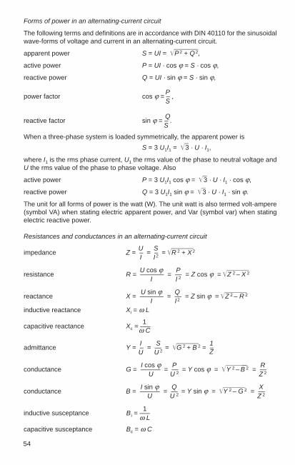
54
Forms of power in an alternating-current circuit
The following terms and definitions are in accordance with DIN 40110 for the sinusoidalwave-forms of voltage and current in an alternating-current circuit.
apparent power S = UI = P 2 + Q 2,
active power P = UI · cos ϕ = S · cos ϕ,
reactive power Q = UI · sin ϕ = S · sin ϕ,
Ppower factor cos ϕ = – ,
S
Qreactive factor sin ϕ = – .
S
When a three-phase system is loaded symmetrically, the apparent power is
S = 3 U1I1 = 3 · U · I1,
where I1 is the rms phase current, U1 the rms value of the phase to neutral voltage andU the rms value of the phase to phase voltage. Also
active power P = 3 U1I1 cos ϕ = 3 · U · I1 · cos ϕ,
reactive power Q = 3 U1I1 sin ϕ = 3 · U · I1 · sin ϕ.
The unit for all forms of power is the watt (W). The unit watt is also termed volt-ampere(symbol VA) when stating electric apparent power, and Var (symbol var) when statingelectric reactive power.
Resistances and conductances in an alternating-current circuit
U Simpedance Z = – = – = R 2 + X 2
I I 2
U cos ϕ Presistance R = ——–— = — = Z cos ϕ = Z 2 – X 2
I I 2
U sin ϕ Qreactance X = ——–— = — = Z sin ϕ = Z 2 – R 2
I I 2
inductive reactance Xi = ω L
1capacitive reactance Xc = —–ω C
I S 1admittance Y = – = — = G 2 + B 2 = –
U U 2 Z
I cos ϕ P Rconductance G = ——— = — = Y cos ϕ = Y 2 – B 2 = —
U U 2 Z 2
I sin ϕ Q Xconductance B = ——— = — = Y sin ϕ = Y 2 – G 2 = —
U U 2 Z 2
1inductive susceptance B i = —–
ω L
capacitive susceptance Bc = ω C

2
55
Fig. 2-2 Fig. 2-3 Vector diagram of resistances Vector diagram of conductances
If the voltage vector U is laid on the real reference axis of the plane of complexnumbers, for the equivalent circuit in Fig. 2-1 with Z = R + j X i: we have
U = U,
I = Iw –j Ib = I (cos ϕ – j sin ϕ),
P QIw = – ; Ib = – ;
U U
S 1) = U I* = U I (cos ϕ + j sin ϕ) = P + j Q,
S = S = U I = P 2 + Q 2,
U U UZ = R + j Xi = — = ——————— = — (cos ϕ + j sin ϕ),
I I (cos ϕ – j sin ϕ) I
U Uwhere R = — cos ϕ and Xi = — sin ϕ,
I I
I IY = G–jB = — = — (cos ϕ – j sin ϕ)
U U
I Iwhere G = — cos ϕ and B i = — sin ϕ.
U U
ω = 2 π f is the angular frequency and ϕ the phase displacement angle of the voltagewith respect to the current. U, I and Z are the numerical values of the alternating-currentquantities U, I and Z.
Complex presentation of sinusoidal time-dependent a. c. quantities
Expressed in terms of the load vector system:
U = I · Z , I = U · YThe symbols are underlined to denotethat they are complex quantities(DIN 1304).
Fig. 2- 1Equivalent circuit diagram
1) S : See DIN 40110I* = conjugated complex current vector

Table 2-5
Alternating-current quantities of basic circuits
Circuit Z Z
1. R R
2. j ω L ω L
3. – j / (ω C ) 1/ω C
4. R + j ω L1) R 2 + (ωL)2
5. R – j / (ω C ) R 2 + 1/(ωC)2
6. j (ω L – 1/(ω C )) 2) (ωL – 1/(ωC))2
7. R + j(ωL–1/(ω C)) 2) R2 + (ωL–1/(ω C))2
R ω L R ω L8. ———–– ——————–
ω L – j R R 2 + (ω L)2
R – j ω C R 2 3) R9. ———––—–— ————–——
1 + (ω C )2 R2 1 + (ω C)2R2
j 110. —–————— ——————–——–
1/(ω L) – ω C (1/ω L)2 – (ω C)2
1 111. —————–——–—–— ————————–————–
1/R + j (ω C – 1/(ω L))
[Y = 1/R 2 + j (ω C – 1/ (ω L))]1/R 2 + (ω C – 1/ (ω L))2
R+ j (L (1– ω2 LC) – R 2 C) R 2+[L (1– ω2 LC) – R 2 C ]212. ———–——–——–—–—–— ————————————––
(1 – ω2 L C)2 + (R ω C)2 (1 – ω2 L C)2 + (R ω C)2
56
1) With small loss angle δ (= 1/ϕ ) ≈ tan δ (error at 4° about 1 ‰): Z ≈ ω L (δ + j). 2) Series resonance (voltage resonance) for ω L = 1 / (ω C ):
1Xres = XL = Xc= L/C res = ———— Zres = R.
2 π LCClose to resonance (∆ < 0.1 res) is Z ≈ R + j Xres · 2 ∆ / res with ∆ = – res
3) With small loss angle δ (= 1/ϕ) ≈ tan δ = –1/(ω C R ):
δ + jZ = —–—ω C
4) Close to resonance (∆ < 0.1 res):
Y = G + j B res · 2 ∆ with ∆ = – res
5) e. g. coil with winding capacitance.
4)
5)
1Bres = C/L: res = ———— Y res = G.
2 π LC

2
57
Table 2-6
Current / voltage relationships
Ohmic Capacitance Inductanceresistance (capacitor) (choke coil)R C L
1 diGeneral law u = i R – ∫ i dt L · —
C dt
u du 1i = – C · — – ∫ u dt
R dt L
Time law u = û sin ω t û sin ω t û sin ω t
1hence u = î R sin ω t = û sin ω t – —— î cos ω t = – û cos ω t ω L î cos ω t = û cos ω t
ω C
û 1i = — sin ω t = î sin ω t ω C û cos ω t = î cos ω t – —– û cos ω t = – î cos ω t
R ω L
Elements of calculation î = û / R ω C û û / (ω L)
û = î R î /(ω C) î ω L
1 π ω L πϕ = 0 arctan ——— = – – arctan —– = –
ω C · 0 2 0 2u and i in phase i leads u by 90 ° i lags u by 90 °
ω ω ωf = —– —– —–
2 π 2 π 2 π
(continued)

58
Table 2-6 (continued)
Ohmic Capacitance Inductanceresistance (capacitor) (choke coil)R C L
Alternating current Z = R – jimpedance —— j ω L
ω C
1|Z | = R —– ω Lω C
Diagrams

2
59
Table 2-7
Numerical values for major materials
Conductor Specific Electric Temperature Densityelectric conductivity coefficient αresistance ρ x = 1/ρ(mm2 Ω/m) (m/mm2 Ω) (K–1) (kg/dm3)
Aluminium, 99.5 % Al, soft 0.0278 36 4 · 20–3 2.7Al-Mg-Si 0.03…0.033 33…30 3.6 · 10–3 2.7Al-Mg 0.06…0.07 17…14 2.0 · 10–3 2.7Al bronze, 90 % Cu, 10 % Al 0.13 7.7 3.2 · 10–3 8.5Bismuth 1.2 0.83 4.5 · 10–3 9.8Brass 0.07 14.3 1.3…1.9 · 10–3 8.5Bronze, 88 % Cu, 12 % Sn 0.18 5.56 0.5 · 10–3 8.6…9Cast iron 0.60…1.60 1.67…0.625 1.9 · 10–3 7.86…7.2Conductor copper, soft 0.01754 57 4.0 · 10–3 8.92Conductor copper, hard 0.01786 56 3.92 · 10–3 8.92Constantan 0.49…0.51 2.04…1.96 –0.05 · 10–3 8.8CrAI 20 5 1.37 0.73 0.05 · 10–3 —CrAI 30 5 1.44 0.69 0.01 · 10–3 —Dynamo sheet 0.13 7.7 4.5 · 10–3 7.8Dynamo sheet alloy (1 to 5 % Si) 0.27…0.67 3.7…1.5 — 7.8Graphite and retort carbon 13…100 0.077…0.01 –0.8…–0.2 · 10–3 2.5…1.5Lead 0.208 4.8 4.0 · 10–3 11.35Magnesium 0.046 21.6 3.8 · 10–3 1.74Manganin 0.43 2.33 0.01 · 10–3 8.4Mercury 0.958 1.04 0.90 · 10–3 13.55Molybdenum 0.054 18.5 4.3 · 10–3 10.2Monel metal 0.42 2.8 0.19 · 10–3 —Nickel silver 0.33 3.03 0.4 · 10–3 8.5
(continued)
2.3 Electrical resistances
2.3.1 Definitions and specific values
An ohmic resistance is present if the instantaneous values of the voltage areproportional to the instantaneous values of the current, even in the event oftime-dependent variation of the voltage or current. Any conductor exhibiting thisproportionality within a defined range (e. g. of temperature, frequency or current)behaves within this range as an ohmic resistance. Active power is converted in anohmic resistance. For a resistance of this kind is
PR = – .
I 2
The resistance measured with direct current is termed the d. c. resistance R– . If theresistance of a conductor differs from the d. c. resistance only as a result of skin effect,we then speak of the a. c. resistance R∼ of the conductor. The ratio expressing theincrease in resistance is
R ∼ a. c. resistanceζ = —– = ———–———– .
R– d. c. resistance
Specific values for major materials are shown in Table 2-7.

60
2.3.2 Resistances in different circuit configurations
Connected in series (Fig. 2-4)
Fig. 2-4
Total resistance = Sum of individual resistancesR = R1 + R2 + R3 + …
The component voltages behave in accordance with the resistances U1 = I R1 etc.
UThe current at all resistances is of equal magnitude I = – .
R
Connected in parallel (Fig. 2-5)
Fig. 2-5
Total conductance = Sum of the individual conductances
1 1– = G = G1 + G2 + G3 + … R = – .R G
Table 2-7 (continued)
Numerical values for major materials
Conductor Specific Electric Temperature Densityelectric conductivity coefficient αresistance ρ x = 1/ρ(mm2 Ω/m) (m/mm2 Ω) (K–1) (kg/dm3)
Ni Cr 30 20 1.04 0.96 0.24 · 10–3 8.3Ni Cr 6015 1.11 0.90 0.13 · 10–3 8.3Ni Cr 80 20 1.09 0.92 0.04 · 10–3 8.3Nickel 0.09 11.1 6.0 · 10–3 8.9Nickeline 0.4 2.5 0.18…0.21 · 10–3 8.3Platinum 0.1 10 3.8…3.9 · 10–3 21.45Red brass 0.05 20 — 8.65Silver 0.0165 60.5 41 · 10–3 10.5Steel, 0.1% C, 0.5 % Mn 0.13…0.15 7.7…6.7 4…5 · 10–3 7.86Steel, 0.25 % C, 0.3 % Si 0.18 5.5 4…5 · 10–3 7.86Steel, spring, 0.8 % C 0.20 5 4…5 · 10–3 7.86Tantalum 0.16 6.25 3.5…10–3 16.6Tin 0.12 8.33 4.4 · 10–3 7.14Tungsten 0.055 18.2 4.6 · 10–3 19.3Zinc 0.063 15.9 3.7 · 10–3 7.23
Resistance varies with temperature, cf. Section 2.3.3

2
61
In the case of n equal resistances the total resistance is the n th part of the individualresistances. The voltage at all the resistances is the same. Total current
U UI = – = Sum of components I1 = — etc.
R R1
The currents behave inversely to the resistances
R R RI1 = I — ; I2 = I — ; I3 = I — .
R1 R2 R3
Transformation delta-star and star-delta (Fig. 2-6)
Fig. 2-6
Conversion from delta to star connection with the same total resistance:
R d2 R d3RS1 = ———————–R d1 + R d2 + R d3
R d3 Rd1RS2 = ———————–R d1 + R d2 + R d3
R d1 R d2RS3 = ———————–R d1 + R d2 + R d3
Conversion from star to delta connection with the same total resistance:
RS1 RS2 + RS2 RS3 + RS3 RS1Rd1 = ——————–———————–RS1
RS1 RS2 + RS2 RS3 + RS3 RS1Rd2 = ——————–————————RS2
RS1 RS2 + RS2 RS3 + RS3 RS1Rd3 = ——————–———————–RS3
Calculation of a bridge between points A and B (Fig. 2-7)
To be found:
1. the total resistance R tot between points A and B,2. the total current I tot between points A and B,3. the component currents in R1 to R 5.
Given:
voltage U = 220 V.resistance R1 = 10 Ω,
R2 = 20 Ω,R3 = 30 Ω,R4 = 40 Ω,R5 = 50 Ω. Fig. 2-7

62
First delta connection CDB is converted to star connection CSDB (Fig. 2-8):
R2 R5 20 · 50R25 = ———–—— = ———–—— = 10 Ω,
R2 + R3 + R5 20 + 30 + 50
R3 R5 30 · 50R35 = ———–—— = ———–—— = 15 Ω,
R2 + R3 + R5 20 + 30 + 50
R2 R3 20 · 30R23 = ———–—— = ———–—— = 6 Ω,
R2 + R3 + R5 20 + 30 + 50
(R1 + R25) (R4 + R35)Rtot = ———–—————— + R23 = R1 + R25 + R4 + R35
(10 +10) (40 + 15)= ———–—————— + 6 = 20.67 Ω.
10 + 10 + 40 + 15
U 220Itot = —– = ——– = 10.65 A.
Rtot 20.67
Rtot – R23 20.67 – 6IR1 = Itot ——–—– = 10.65 · ————– = 7.82 A,
R1 + R25 10 + 10
Rtot – R23 20.67 – 6IR4 = Itot —–—–—– = 10.65 · ————– = 2.83 A,
R4 + R35 40 + 15
By converting the delta connection CDA to star con-nection CSDA, we obtain the following values (Fig. 2-9):R15 = 5 Ω; R45 = 20Ω; R14 = 4 Ω; IR2 = 7.1A; IR3 = 3.55 A.
With alternating current the calculations are somewhat more complicated and arecarried out with the aid of resistance operators. Using the symbolic method ofcalculation, however, it is basically the same as above.
2.3.3 The influence of temperature on resistance
The resistance of a conductor isl · ρ l
R = ––— = ——A x · A
wherel = Total length of conductor A = Cross-sectional area of conductor ρ = Specific resistance (at 20 °C)
1x = – Conductance
ρα = Temperature coefficient.
Values for ρ, x and α are given in Table 2-7 for a temperature of 20 °C.
For other temperatures ϑ1) (ϑ in °C)ρϑ = ρ20 [1 + α (ϑ – 20)]
1) Valid for temperatures from – 50 to + 200 °C.
Fig. 2-9
Fig. 2-8

2
63
and hence for the conductor resistance
lRϑ = – · ρ20 [1 + α (ϑ – 20)].
A
Similarly for the conductivity
xϑ = x20 [1 + α (ϑ – 20)]–1
The temperature rise of a conductor or a resistance is calculated as
Rw / R k –1∆ ϑ = ————– ·
αThe values R k and Rw are found by measuring the resistance of the conductor orresistance in the cold and hot conditions, respectively.
Example:
The resistance of a copper conductor of l = 100 m and A = 10 mm2 at 20 °C is
100 · 0.0175R20 = —————– = 0.175 Ω.
10
If the temperature of the conductor rises to ϑ = 50 °C, the resistance becomes
100 R50 = —– · 0.0175 [1 + 0.004 (50 – 20)] ≈ 0.196 Ω.
10
2.4 Relationships between voltage drop, power loss and conductorcross section
Especially in low-voltage networks is it necessary to check that the conductor cross-section, chosen with respect to the current-carrying capacity, is adequate as regardsthe voltage drop. It is also advisable to carry out this check in the case of very longconnections in medium-voltage networks. (See also Sections 6.1.6 and 13.2.3).
Direct current
2 · l · I 2 · l · Pvoltage drop ∆ U = R'L · 2 · l · I = ——— = ————
x · A x · A · U
percentage ∆ U R ’L · 2 · l · Ivoltage drop ∆ u = —— 100 % = ————— 100 %
Un Un
2 · l · P 2
power loss ∆ P = I 2 R'L 2 · l = ————x · A · U 2
percentage ∆ P I 2 R'L · 2 · lpower loss ∆ p = —— 100 % = ————— 100 %
Pn Pn
conductor 2 · l · I 2 · l · I 2 · l · Pcross section A = ———— = ————– 100 % = ————— 100 %
x · ∆ U x · ∆ u · U ∆ p · U 2 · x

64
Three-phase current
voltage drop2) ∆ U = 3 · I · l (R'L · cos ϕ + X'L · sin ϕ)
∆ U 3 · I · l (R ’L · cos ϕ + X'L · sin ϕ)percentage ∆ u = —– 100 % = —————–————————— 100 %voltage drop2) Un Un
l · P 2
power loss ∆ P = 3 · I 2 R'L · l = —————–——–x · A · U 2 · cos2 ϕ
percentage ∆ P 3 I 2 · R'L · lpower loss ∆ p = —— 100 % = ————— 100 %
Pn Pn
l · cos ϕconductor A = ———————————–cross-section1) ∆ U
x (——– – X'L · l · sin ϕ)3 · I
Single-phase alternating current
voltage drop2) ∆ U = I · 2 · l (R'L · cos ϕ + X'L · sin ϕ)
∆ U I · 2 · l (R'L · cos ϕ + X'L · sin ϕ)percentage ∆ u = —– 100 % = —————–————————voltage drop2) Un Un
2 · l · P 2
power loss ∆ P = I 2R'L · 2 · l = —————––——x · A · U 2 · cos2 ϕ
percentage ∆ P I 2 · R'L · 2 · lpower loss ∆ p = —— 100 % = —————– 100 %
Pn Pn
2 · l cos ϕconductor A = ———————————–— cross-section1) ∆ U
x (—— — X'L· 2 · l · sin ϕ)I2 · l cos ϕ
——————————————–∆ u · Un
x (———— — X'L· 2 · l · sin ϕ)I · 100 %
In single-phase and three-phase a.c. systems with cables and lines of less than 16 mm2
the inductive reactance can usually be disregarded. It is sufficient in such cases tocalculate only with the d.c. resistance.1) Reactance is slightly dependent on conductor cross section. 2) Longitudinal voltage drop becomes effectively apparent.
l = one-way length of R'L = Resistance P = Active power to beconductor per km transmitted (P = Pn)
U = phase-to-phase X'L = Reactance I = phase-to-phasevoltage per km current
l · cos ϕ= ————————————–———
∆ u · Ux (——————– — X'L · l · sin ϕ)3 · I · 100 %
=

2
65
Table 2-8
Effective resistances per unit length of PVC-insulated cables with copper conductors asper DIN VDE 0271 for 0.6/1 kV
Number D. C. Ohmic Induc- Effective resistance per unit lengthof conduc- resist- resist- tive R'L · cos ϕ + X'L · sin ϕtors and ance ance at react- at cos ϕcross- at 70 °C 70 °C ance 0.95 0.9 0.8 0.7 0.6section
R'L– R'L~ X'Lmm2 Ω /km Ω /km Ω /km Ω /km Ω /km Ω /km Ω /km Ω /km
4 × 1.5 14.47 14.47 0.115 13.8 13.1 11.65 10.2 8.774 × 2.5 8.71 8.71 0.110 8.31 7.89 7.03 6.18 5.314 × 4 5.45 5.45 0.107 5.21 4.95 4.42 3.89 3.364 × 6 3.62 3.62 0.100 3.47 3.30 2.96 2.61 2.254 × 10 2.16 2.16 0.094 2.08 1.99 1.78 1.58 1.374 × 16 1.36 1.36 0.090 1.32 1.26 1.14 1.020 0.8884 × 25 0.863 0.863 0.086 0.847 0.814 0.742 0.666 0.5874 × 35 0.627 0.627 0.083 0.622 0.60 0.55 0.498 0.4434 × 50 0.463 0.463 0.083 0.466 0.453 0.42 0.38 0.3444 × 70 0.321 0.321 0.082 0.331 0.326 0.306 0.283 0.2584 × 95 0.231 0.232 0.082 0.246 0.245 0.235 0.221 0.2054 × 120 0.183 0.184 0.080 0.2 0.2 0.195 0.186 0.1744 × 150 0.149 0.150 0.080 0.168 0.17 0.168 0.162 0.1544 × 185 0.118 0.1202 0.080 0.139 0.143 0.144 0.141 0.1364 × 240 0.0901 0.0922 0.079 0.112 0.117 0.121 0.121 0.1194 × 300 0.0718 0.0745 0.079 0.0954 0.101 0.107 0.109 0.108
Example:
A three-phase power of 50 kW with cos ϕ = 0.8 is to be transmitted at 400 V over a line100 m long. The voltage drop must not exceed 2 %. What is the required cross sectionof the line?
The percentage voltage drop of 2 % is equivalent to
∆ u 2 %∆ U = ——– Un = ——— 400 V = 8.0 V.
100 % 100 %
The current is
P 50 kWI = ——————– = ——————— = 90 A.
3 · U · cos ϕ 3 · 400 V · 0.8
Calculation is made easier by Table 2-8, which lists the effective resistance per unit length R ’L · cos ϕ + X ’L · sin ϕ for the most common cables and conductors.Rearranging the formula for the voltage drop yields
∆ U 8.0R ’L · cos ϕ + X ’L · sin ϕ = ———— = ———————— = 0.513 Ω /km.
3 · I · l 3 · 90 A · 0.1 km
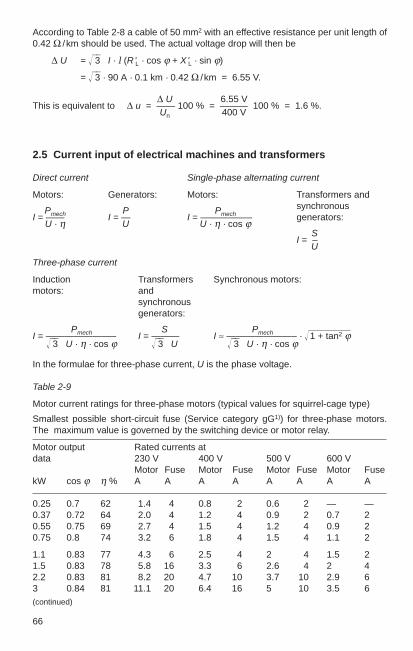
66
According to Table 2-8 a cable of 50 mm2 with an effective resistance per unit length of0.42 Ω /km should be used. The actual voltage drop will then be
∆ U = 3 · I · l (R'L · cos ϕ + X'L · sin ϕ)
= 3 · 90 A · 0.1 km · 0.42 Ω /km = 6.55 V.
∆ U 6.55 VThis is equivalent to ∆ u = —— 100 % = ——— 100 % = 1.6 %.
Un 400 V
2.5 Current input of electrical machines and transformers
Direct current Single-phase alternating current
Motors: Generators: Motors: Transformers and
Pmech P Pmechsynchronous
I = —— I = — I = ————–— generators:U · η U U · η · cos ϕ
SI = –
U
Three-phase current
Induction Transformers Synchronous motors:motors: and
synchronousgenerators:
Pmech S PmechI = ———————– I = ——— I ≈ ———————– · 1 + tan2 ϕ3 · U · η · cos ϕ 3 · U 3 · U · η · cos ϕ
In the formulae for three-phase current, U is the phase voltage.
Table 2-9
Motor current ratings for three-phase motors (typical values for squirrel-cage type)
Smallest possible short-circuit fuse (Service category gG1)) for three-phase motors.The maximum value is governed by the switching device or motor relay.
Motor output Rated currents atdata 230 V 400 V 500 V 600 V
Motor Fuse Motor Fuse Motor Fuse Motor FusekW cos ϕ η % A A A A A A A A
0.25 0.7 62 1.4 4 0.8 2 0.6 2 — —0.37 0.72 64 2.0 4 1.2 4 0.9 2 0.7 20.55 0.75 69 2.7 4 1.5 4 1.2 4 0.9 20.75 0.8 74 3.2 6 1.8 4 1.5 4 1.1 2
1.1 0.83 77 4.3 6 2.5 4 2 4 1.5 21.5 0.83 78 5.8 16 3.3 6 2.6 4 2 42.2 0.83 81 8.2 20 4.7 10 3.7 10 2.9 63 0.84 81 11.1 20 6.4 16 5 10 3.5 6(continued)
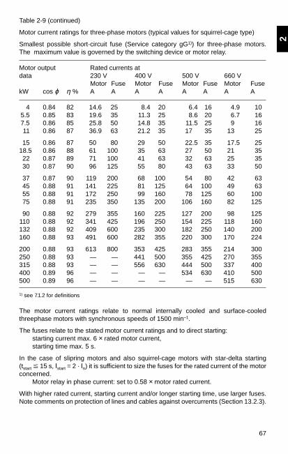
2
67
Table 2-9 (continued)
Motor current ratings for three-phase motors (typical values for squirrel-cage type)
Smallest possible short-circuit fuse (Service category gG1)) for three-phase motors.The maximum value is governed by the switching device or motor relay.
Motor output Rated currents atdata 230 V 400 V 500 V 660 V
Motor Fuse Motor Fuse Motor Fuse Motor FusekW cos ϕ η % A A A A A A A A
4 0.84 82 14.6 25 8.4 20 6.4 16 4.9 105.5 0.85 83 19.6 35 11.3 25 8.6 20 6.7 167.5 0.86 85 25.8 50 14.8 35 11.5 25 9 1611 0.86 87 36.9 63 21.2 35 17 35 13 25
15 0.86 87 50 80 29 50 22.5 35 17.5 2518.5 0.86 88 61 100 35 63 27 50 21 3522 0.87 89 71 100 41 63 32 63 25 3530 0.87 90 96 125 55 80 43 63 33 50
37 0.87 90 119 200 68 100 54 80 42 6345 0.88 91 141 225 81 125 64 100 49 6355 0.88 91 172 250 99 160 78 125 60 10075 0.88 91 235 350 135 200 106 160 82 125
90 0.88 92 279 355 160 225 127 200 98 125110 0.88 92 341 425 196 250 154 225 118 160132 0.88 92 409 600 235 300 182 250 140 200160 0.88 93 491 600 282 355 220 300 170 224
200 0.88 93 613 800 353 425 283 355 214 300250 0.88 93 — — 441 500 355 425 270 355315 0.88 93 — — 556 630 444 500 337 400400 0.89 96 — — — — 534 630 410 500500 0.89 96 — — — — — — 515 630
1) see 7.1.2 for definitions
The motor current ratings relate to normal internally cooled and surface-cooledthreephase motors with synchronous speeds of 1500 min–1.
The fuses relate to the stated motor current ratings and to direct starting: starting current max. 6 × rated motor current, starting time max. 5 s.
In the case of slipring motors and also squirrel-cage motors with star-delta starting(tstart 15 s, Istart = 2 · In) it is sufficient to size the fuses for the rated current of the motorconcerned.
Motor relay in phase current: set to 0.58 × motor rated current.
With higher rated current, starting current and/or longer starting time, use larger fuses.Note comments on protection of lines and cables against overcurrents (Section 13.2.3).
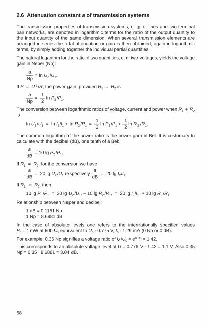
68
2.6 Attenuation constant a of transmission systems
The transmission properties of transmission systems, e. g. of lines and two-terminalpair networks, are denoted in logarithmic terms for the ratio of the output quantity tothe input quantity of the same dimension. When several transmission elements arearranged in series the total attenuation or gain is then obtained, again in logarithmicterms, by simply adding together the individual partial quantities.
The natural logarithm for the ratio of two quantities, e. g. two voltages, yields the voltagegain in Neper (Np):
a—– = In U2 /U1.Np
If P = U 2 /R, the power gain, provided R1 = R2 is
a 1—– = — In P2 /P1.Np 2
The conversion between logarithmic ratios of voltage, current and power when R1 R2
is1 1
In U2 /U1 = In I2/l1 + In R2 /R1 = — In P2 /P1 + — In R 2 /R1.2 2
The common logarithm of the power ratio is the power gain in Bel. It is customary tocalculate with the decibel (dB), one tenth of a Bel:
a—– = 10 lg P2 /P1.dB
If R1 = R2, for the conversion we havea a
—– = 20 lg U2 /U1 respectively —– = 20 lg I2/l1.dB dB
If R1 R2, then
10 lg P2 /P1 = 20 lg U2 /U1, – 10 lg R2 /R1, = 20 lg I2/l1, + 10 lg R2 /R1.
Relationship between Neper and decibel:
1 dB = 0.1151 Np1 Np = 8.6881 dB
In the case of absolute levels one refers to the internationally specified values P0 = 1 mW at 600 Ω, equivalent to U0 · 0.775 V, I0 · 1.29 mA (0 Np or 0 dB).
For example, 0.36 Np signifies a voltage ratio of U /U0 = e0.35 = 1.42.
This corresponds to an absolute voltage level of U = 0.776 V · 1.42 = 1.1 V. Also 0.35Np = 0.35 · 8.6881 = 3.04 dB.

3
69
3 Calculation of Short-Circuit Currentsin Three-Phase Systems
3.1 Terms and definitions
3.1.1 Terms as per DIN VDE 0102 / IEC 909
Short circuit: the accidental or deliberate connection across a comparatively lowresistance or impedance between two or more points of a circuit which usually havediffering voltage.Short-circuit current: the current in an electrical circuit in which a short circuit occurs.Prospective (available) short-circuit current: the short-circuit current which would ariseif the short circuit were replaced by an ideal connection having negligible impedancewithout alteration of the incoming supply.Symmetrical short-circuit current: root-mean-square (r.m.s.) value of the symmetricalalternating-current (a.c.) component of a prospective short-circuit current, taking noaccount of the direct-current (d.c.) component, if any.Initial symmetrical short-circuit current I k": the r.m.s. value of the symmetrical a.c.component of a prospective short-circuit current at the instant the short circuit occurs ifthe short-circuit impedance retains its value at time zero.Initial symmetrical (apparent) short-circuit power Sk": a fictitious quantity calculated asthe product of initial symmetrical short-circuit current I k", nominal system voltage Un andthe factor 3.D.C. (aperiodic) component iDC of short-circuit current: the mean value between the upperand lower envelope curve of a short-circuit current decaying from an initial value to zero. Peak short-circuit current i p: the maximum possible instantaneous value of aprospective short-circuit current.Symmetrical short-circuit breaking current Ia: the r.m.s. value of the symmetrical a.c.component of a prospective short-circuit current at the instant of contact separation bythe first phase to clear of a switching device.Steady-state short-circuit current Ik: the r.m.s. value of the symmetrical a.c. component ofa prospective short-circuit current persisting after all transient phenomena have died away.(Independent) Voltage source: an active element which can be simulated by an idealvoltage source in series with a passive element independently of currents and othervoltages in the network.Nominal system voltage Un: the (line-to-line) voltage by which a system is specifiedand to which certain operating characteristics are referred.Equivalent voltage source cUn / 3: the voltage of an ideal source applied at theshort-circuit location in the positive-sequence system as the network’s only effectivevoltage in order to calculate the short-circuit currents by the equivalent voltage sourcemethod.Voltage factor c: the relationship between the voltage of the equivalent voltage sourceand Un / 3.Subtransient voltage E" of a synchronous machine: the r.m.s. value of the symmetricalinterior voltages of a synchronous machine which is effective behind the subtransientreactance Xd" at the instant the short circuit occurs.Far-from-generator short circuit: a short circuit whereupon the magnitude of thesymmetrical component of the prospective short-circuit current remains essentiallyconstant.
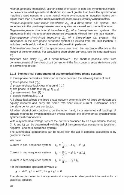
70
Near-to-generator short circuit: a short circuit whereupon at least one synchronous machi-ne delivers an initial symmetrical short-circuit current greater than twice the synchronousmachine’s rated current, or a short circuit where synchronous or induction motors con-tribute more than 5 % of the initial symmetrical short-circuit current Ik" without motors.Positive-sequence short-circuit impedance Z(1) of a three-phase a.c. system: theimpedance in the positive-phase-sequence system as viewed from the fault location.Negative-sequence short-circuit impedance Z(2) of a three-phase a.c. system: theimpedance in the negative-phase-sequence system as viewed from the fault location.Zero-sequence short-circuit impedance Z (0) of a three-phase a.c. system: theimpedance in the zero-phase-sequence system as viewed from the fault location. Itincludes the threefold value of the neutral-to-earth impedance.Subtransient reactance X"d of a synchronous machine: the reactance effective at theinstant of the short circuit. For calculating short-circuit currents, use the saturated valueX"d.Minimum time delay tmin of a circuit-breaker: the shortest possible time fromcommencement of the short-circuit current until the first contacts separate in one poleof a switching device.
3.1.2 Symmetrical components of asymmetrical three-phase systems
In three-phase networks a distinction is made between the following kinds of fault:a) three-phase fault (I "k 3) b) phase-to-phase fault clear of ground (I "k 2) c) two-phase-to-earth fault (I "k 2 E; I "k E 2 E) d) phase-to-earth fault (I "k 1) e) double earth fault (I "k E E)A 3-phase fault affects the three-phase network symmetrically. All three conductors areequally involved and carry the same rms short-circuit current. Calculation needtherefore be for only one conductor.All other short-circuit conditions, on the other hand, incur asymmetrical loadings. Asuitable method for investigating such events is to split the asymmetrical system into itssymmetrical components.With a symmetrical voltage system the currents produced by an asymmetrical loading(I1, I2 and I3) can be determined with the aid of the symmetrical components (positive-,negative- and zero-sequence system).The symmetrical components can be found with the aid of complex calculation or bygraphical means.
We have: 1
Current in pos.-sequence system I m = – (I1 + a I 2 + a2 I 3)31
Current in neg.-sequence system I g = – (I1 + a2 I 2 + a I 3)31
Current in zero-sequence system I o = – (I1 + I 2 + I 3)3
For the rotational operators of value 1:
a = ej120˚; a2 = ej240˚; 1 + a + a2 = 0
The above formulae for the symmetrical components also provide information for agraphical solution.

3
71
If the current vector leading the current in the reference conductor is rotated 120°backwards, and the lagging current vector 120 ° forwards, the resultant is equal to threetimes the vector Im in the reference conductor. The negative-sequence components areapparent.
If one turns in the other direction, the positive-sequence system is evident and theresultant is three times the vector I g in the reference conductor.
Geometrical addition of all three current vectors (I1, I 2 and I 3) yields three times thevector I 0 in the reference conductor.
If the neutral conductor is unaffected, there is no zero-sequence system.
3.2 Fundamentals of calculation according to DIN VDE 0102 / IEC 909
In order to select and determine the characteristics of equipment for electrical networksit is necessary to know the magnitudes of the short-circuit currents and short-circuitpowers which may occur.
The short-circuit current at first runs asymmetrically to the zero line, Fig. 3-1. It containsan alternating-current component and a direct-current component.
Fig. 3-1
Curve of short-circuit current: a) near-to-generator fault, b) far-from-generator fault I "k initial symmetrical short-circuit current, i p peak short-circuit current, I k steady stateshort-circuit current, A initial value of direct current, 1 upper envelope, 2 lowerenvelope, 3 decaying direct current.
i pi p

72
Calculatlon of initial symmetrical short-circuit current I "k
The calculation of short-circuit currents is always based on the assumption of a deadshort circuit. Other influences, especially arc resistances, contact resistances, conduc-tor temperatures, inductances of current transformers and the like, can have the effectof lowering the short-circuit currents. Since they are not amenable to calculation, theyare accounted for in Table 3-1 by the factor c.
Initial symmetrical short-circuit currents are calculated with the equations in Table 3-2.
Table 3-1
Voltage factor c
Nominal voltage Voltage factor c for calculatingthe greatest the smallestshort-circuit current short-circuit current
c max c min
Low voltage100 V to 1000 V(see IEC 38, Table I)a) 230 V / 400 V 1.00 0.95b) other voltages 1.05 1.00
Medium voltage>1 kV to 35 kV 1.10 1.00(see IEC 38, Table III)
High-voltage> 35 kV to 230 kV 1.10 1.00(see IEC 38, Table IV)380 kV 1.10 1.00
Note: cUn should not exceed the highest voltage Um for power system equipment.

3
73
Table 3-2
Formulae for calculating initial short-circuit current and short-circuit powers
Kind of fault Dimension equations Numerical equations(IEC 909) of the % / MVA systems
Three-phase faultwith orwithout earth fault
Phase-to-phasefault clearof ground
Two-phase-to-earth fault
Phase-to-earth fault
In the right-hand column of the Table, I "k is in kA, S"k in MVA, Un in kV and Z in % / MVA.The directions of the arrows shown here are chosen arbitrarily.
1.1 · UnI "k 3 = ———–3 Z1
3 · 1.1 · UnI "k 1 = ——————–Z1 + Z 2 + Z 0
1.1 · UnI "k 2 = ——–—–Z1 + Z 2
1.1 · 100 % 1I "k 3 = ————–– · —
3 Z1 Un
1.1 ·100 % 1I "k 2 = ————– · —
Z1 + Z 2 Un
3 · 1.1 · 100 % 1I "k 1 = ————–——– · —
Z1 + Z 2 + Z 0 Un
3 · 1.1 UnI"kE2E= ———————– Z1Z1 + Z 0 + Z 0 —Z 2
3 · 1.1 · 100 % 1I"kE2E= ———————– · —
Z1Z1 + Z 0 + Z 0 —Un
Z 2
1.1 · 100 %S"k = ————––
z1
S"k = 3 Un I "k 3

74
Calculation of peak short-circuit current ip
When calculating the peak short-circuit current ip, sequential faults are disregarded.Three-phase short circuits are treated as though the short circuit occurs in all threeconductors simultaneously. We have:
ip = κ · 2 · I "k .
The factor κ takes into account the decay of the d. c. component. It can be calculatedas
κ = 1.02 + 0.98 e–3 R/X or taken from Fig. 3-2.
Exact calculation of ip with factor κ is possible only in networks with branches havingthe same ratios R/X. If a network includes parallel branches with widely different ratiosR/X, the following methods of approximation can be applied:
a) Factor κ is determined uniformly for the smallest ratio R/X. One need only considerthe branches which are contained in the faulted network and carry partialshort-circuit currents.
b) The factor is found for the ratio R/X from the resulting system impedance Zk = Rk + jXk at the fault location, using 1.15 · κk for calculating ip. In low-voltagenetworks the product 1.15 · κ is limited to 1.8, and in high-voltage networks to 2.0.
c) Factor κ can also be calculated by the method of the equivalent frequency as in IEC 909 para. 9.1.3.2.
The maximum value of κ = 2 is attained only in the theoretical limiting case with anactive resistance of R = 0 in the short-circuit path. Experience shows that with ashort-circuit at the generator terminals a value of κ = 1.8 is not exceeded with machines< 100 MVA.
With a unit-connected generator and high-power transformer, however, a value of κ = 1.9 can be reached in unfavourable circumstances in the event of a short circuitnear the transformer on its high-voltage side, owing to the transformer’s very small ratioR/X. The same applies to networks with a high fault power if a short circuit occurs aftera reactor.

3
75
Calculation of steady-state short-circuit current Ik
Three-phase fault with single supply
Ik = I"kQ network
Ik = λ · IrG synchronous machine
Three-phase fault with single supply from more than one side
Ik = IbkW + I"kQ
Ibkw symmetrical short-circuit breaking current of a power plant
I"kQ initial symmetrical short-circuit current of network
Three-phase fault in a meshed network
Ik = I"koM
I"koM initial symmetrical short-circuit current without motors
Ik depends on the excitation of the generators, on saturation effects and on changes inswitching conditions in the network during the short circuit. An adequate approximationfor the upper and lower limit values can be obtained with the factors λmax and λmin,Fig. 3-3 and 3-4. IrG is the rated current of the synchronous machine.
For Xdsat one uses the reciprocal of the no-load/short-circuit ratio Ik0/IrG(VDE 0530 Part 1).
The 1st series of curves of λmax applies when the maximum excitation voltage reaches1.3 times the excitation voltage for rated load operation and rated power factor in thecase of turbogenerators, or 1.6 times the excitation for rated load operation in the caseof salient-pole machines.
The 2nd series of curves of λmax applies when the maximum excitation voltage reaches1.6 times the excitation for rated load operation in the case of turbogenerators, or 2.0times the excitation for rated load operation in the case of salient-pole machines.
Fig. 3-2
Factor κ

76
Fig. 3-4
Factors λ for turbogenerators in relation to ratio I "kG / IrG and saturated synchronousreactance Xd of 1.2 to 2.2, —— λmax, – · – λmin;a) Series 1 Ufmax / Ufr = 1.3; b) Series 2 Ufmax / Ufr = 1.6.
Three-phase short circuit I"kG /IrG Three-phase short circuit I"kG /IrG
Fig. 3-3
Factors λ for salient-pole machines in relation to ratio I"kG /IrG and saturatedsynchronous reactance Xd of 0.6 to 2.0, —— λmax, – · – λmin;a) Series 1 U fmax / U fr = 1.6; b) Series 2 Ufmax / U fr = 2.0.
Three-phase short circuit I"kG /IrG Three-phase short circuit I"kG /IrG

3
77
Calculation of symmetrical breaking current Ia
Three-phase fault with single supply
I a = µ · I"kG synchronous machine
I a = µ · q · I"kM induction machine
I a = I"kQ network
Three-phase fault with single supply from more than one side
I a = I aKW + I"kQ + I aM
I aKW symmetrical short-circuit breaking current of a power plant
I kQ initial symmetrical short-circuit current of a network
I aM symmetrical short-circuit breaking current of an induction machine
Three-phase fault in a meshed network
I a = I"k
A more exact result for the symmetrical short-circuit breaking current is obtained withIEC 909 section 12.2.4.3, equation (60).
The factor µ denotes the decay of the symmetrical short-circuit current during theswitching delay time. It can be taken from Fig. 3-5 or the equations.
µ = 0.84 + 0.26 e–0.26 I"kG/ IrG for tmin = 0.02 s
µ = 0.71 + 0.51 e–0.30 I"kG/ IrG for tmin = 0.05 s
µ = 0.62 + 0.72 e–0.32 I"kG/ IrG for tmin = 0.10 s
µ = 0.56 + 0.94 e–0.38 I"kG/ IrG for tmin = 0.25 s
µmax = 1
Fig. 3-5
Factor µ for calculating the symmetrical short-circuit breaking current Ia as a function ofratio I"kG /IrG or I"kM / IrM, and of switching delay time tmin of 0.02 to 0.25 s.
I"kG / I rG or I "kM / I rM

78
If the short circuit is fed by a number of independent voltage sources, the symmetricalbreaking currents may be added.
With compound excitation or converter excitation one can put µ = 1 if the exact value isnot known. With converter excitation Fig. 3-5 applies only if tv ≤ 0.25 s and themaximum excitation voltage does not exceed 1.6 times the value at nominal excitation.In all other cases put µ = 1.
The factor q applies to induction motors and takes account of the rapid decay of themotor’s short-circuit current owing to the absence of an excitation field. It can be takenfrom Fig. 3-6 or the equations.
q = 1.03 + 0.12 ln m for tmin = 0.02 s
q = 0.79 + 0.12 ln m for tmin = 0.05 s
q = 0.57 + 0.12 ln m for tmin = 0.10 s
q = 0.26 + 0.12 ln m for tmin = 0.25 s
qmax = 1
Fig. 3-6
Factor q for calculating the symmetrical short-circuit breaking current of inductionmotors as a function of the ratio motor power / pole pair and of switching delay time tmin
of 0.02 to 0.25 s.
Taking account of transformers
The impedances of equipment in the higher- or lower-voltage networks have to be re-calculated with the square of the rated transformer ratio ür (main tap).
The influence of motors
Synchronous motors and synchronous condensers are treated as synchronousgenerators.
Induction motors contribute values to I"k, ip and I a and in the case of a two-phase shortcircuit, to Ik as well.
Motor power / pole pair

3
79
The heaviest short-circuit currents I"k, ip, Ia and Ik in the event of three-phase and two-phase short circuits are calculated as shown in Table 3-3.
For calculating the peak short-circuit current:κm = 1.65 for HV motors, motor power per pole pair < 1MWκm = 1.75 for HV motors, motor power per pole pair ≥ 1MWκm = 1.3 for LV motors
Table 3-3
To calculate short-circuit currents of induction motors with terminal short circuit
three-phase two-phase
Initial symmetricalshort-circuit current
Peak short-circuit current
Symmetrical short-circuitbreaking current
Steady-stateshort-circuit current
The influence of induction motors connected to the faulty network by way oftransformers can be disregarded if
c · UnI"k3M = ———3 · ZM
3I"k2M = — I "k3M
2
3I "p2M = — ip3M2
I"p3M = κm 2 I "k3M
3I "a2M ~ — I "k3M2
Ia3M = I "k3M
1I k2M ~ — I "k3M2
I"k3M = 0
Σ PrM 0.8——– ———————Σ S rT 100 Σ S rT—–——— – 0.3.
S"k
Here,
Σ PrM is the sum of the ratings of all high-voltage and such low-voltage motors as needto be considered,
Σ SrT is the sum of the ratings of all transformers feeding these motors and
S"k is the initial fault power of the network (without the contribution represented bythe motors).
To simplify calculation, the rated current IrM of the low-voltage motor group can be takenas the transformer current on the low-voltage side.
%/MVA system
The %/MVA system is particularly useful for calculating short-circuit currents in high-voltage networks. The impedances of individual items of electrical equipment in %/MVA can be determined easily from the characteristics, see Table 3-4.

80
Table 3-4
Formulae for calculating impedances or reactances in %/MVA
Network component Impedance z or reactance x
Synchronous x"d x"d = Subtransient reactance in %machine Sr
Sr = Rated apparent power in MVA
Transformer u k u k = Impedance voltage drop in %Sr
Sr = Rated apparent power in MVA
Current-limiting ur ur = Rated voltage drop in %reactor SD
SD = Throughput capacity in MVA
Induction motor Ir/Istart · 100 %I r = Rated current
SrIstart = Starting current (with rated voltage
and rotor short-circuited)
Sr = Rated apparent power in MVA
Line Z´ · l · 100 % Z´ = Impedance per conductor in Ω /kmU 2
n Un = Nominal system voltage in kVl = Length of line in km
Series – Xc · 100 % Xc = Reactance per phase in Ωcapacitor U 2
nUn = Nominal system voltage in kV
100 %Shunt capacitor – ——— Sr = Rated apparent power in MVASr
Network 1.1 · 100 % S"kQ = Three-phase initial symmetrical—————short-circuit power at point ofS"kQconnection Q in MVA
Table 3-5
Reference values for Z 2 /Z1 and Z 2 /Z 0
Z 2 /Z1 Z 2 /Z 0
to calculateI"k near to generator 1 –
far from generator 1 –Ik near to generator 0.05…0.25 –
far from generator 0.25…1 –
Networks with isolated neutral – 0with earth compensation – 0with neutral earthed via impedances – 0…0.25
Networks with effectively earthed neutral – > 0.25
Calculating short-circuit currents by the %/MVA system generally yields sufficientlyaccurate results. This assumes that the ratios of the transformers are the same as theratios of the rated system voltages, and also that the nominal voltage of the networkcomponents is equal to the nominal system voltage at their locations.
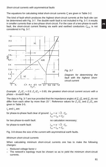
3
81
Short-circuit currents with asymmetrical faults
The equations for calculating initial short-circuit currents I"k are given in Table 3-2.
The kind of fault which produces the highest short-circuit currents at the fault site canbe determined with Fig. 3-7. The double earth fault is not included in Fig. 3-7; it resultsin smaller currents than a two-phase short-circuit. For the case of a two-phase-to-earthfault, the short-circuit current flowing via earth and earthed conductors I"kE2E is notconsidered in Fig. 3-7.
Fig. 3-7
Diagram for determining thefault with the highest short-circuit current
Example: Z2 /Z1 = 0.5; Z2 /Z0 = 0.65, the greatest short-circuit current occurs with aphase – to-earth fault.
The data in Fig. 3-7 are true provided that the impedance angles of Z 2 /Z1 and Z 0 do notdiffer from each other by more than 15 °. Reference values for Z 2 /Z1 and Z 2 /Z 0 aregiven in Table 3-5.
i p and I k are:
for phase-to-phase fault clear of ground: i p2 = κ · 2 · I"k2,I k2 = Ia2 = I"k2;
for two-phase-to-earth fault: no calculation necessary;
for phase-to-earth fault: i p1 = κ · 2 · I"k1,I k1 = Ia1 = I"k1.
Fig. 3-8 shows the size of the current with asymmetrical earth faults.
Minimum short-circuit currents
When calculating minimum short-circuit currents one has to make the followingchanges:
– Reduced voltage factor c– The network’s topology must be chosen so as to yield the minimum short-circuit
currents.
k1
k2E
k2
k3

82
– Motors are to be disregarded– The resistances RL of the lines must be determined for the conductor temperature te
at the end of the short circuit (RL20 conductor temperature at 20 °C).
RL = [1 + 0.004 (te – 20 °C) / °C] · R L20
For lines in low-voltage networks it is sufficient to put te = 80°C.
Fig. 3-8
Initial short-circuit current I"k at the fault location with asymmetrical earth faults innetworks with earthed neutral:
S"k = 3 · Ul"k3 = Initial symmetrical short-circuit power,I"kE2E Initial short-circuit current via earth for two-phase-to-earth fault,I"k1 Initial short-circuit current with phase-to-earth fault,X1, X 0 Reactances of complete short-circuit path in positive- and zero-phase sequence
system (X2 = X1)

3
83
3.3 Impedances of electrical equipment
The impedances of electrical equipment are generally stated by the manufacturer. Thevalues given here are for guidance only.
3.3.1 System infeed
The effective impedance of the system infeed, of which one knows only the initialsymmetrical fault power S"kQ or the initial symmetrical short-circuit current I"kQ at junctionpoint Q, is calculated as:
c · U2nQ c · UnQZQ = ———– = ——–—
S"kQ 3 · I"kQ
c · U 2nQ 1 c · UnQ 1
ZQ = ———– · — = ——––— · — .S"kQ ü 2
r 3 · I"kQ ü 2r
3.3.2 Electrical machines
Synchronous generators with direct system connection
For calculating short-circuit currents the positive- and negative-sequence impedancesof the generators are taken as
ZGK = KG · ZG = KG (RG + jX"d)
with the correction factor
Un cmaxKG = — · —————–—Urg 1 + X"d · sin ϕrg
Here:
cmax Voltage factor
Un Nominal system voltage
Here UnQ Nominal system voltage
S"kQ Initial symmetrical short-circuit power
I "kQ Initial symmetrical short-circuit current
ZQ = RQ + jXQ, effective impedance of system infeed for short-circuit currentcalculation
XQ = Z 2Q – R 2
Q.
If no precise value is known for the equivalent active resistance RQ of the systeminfeed, one can put RQ = 0.1 XQ with XQ = 0.995 ZQ. The effect of temperature can bedisregarded.
If the impedance is referred to the low-voltage side of the transformer, we have

84
UrG Rated voltage of generator
ZGK Corrected impedance of generator
ZG Impedance of generator (ZG = RG + jX"d)
X"d Subtransient reactance of generator referred to impedance
x"d = X"d / ZrG ZrG = U 2rG /SrG
It is sufficiently accurate to put:
RG = 0.05 · X"d for rated powers 100 MVA with high-voltage
RG = 0.07 · X"d for rated powers < 100 MVA generators
RG = 0.15 · X"d for low-voltage generators.
The factors 0.05, 0.07 and 0.15 also take account of the decay of the symmetricalshort-circuit current during the first half-cycle.Guide values for reactances are shown in Table 3-6.
Table 3-6
Reactances of synchronous machines
Generator type Turbogenerators Salient-pole generatorswith damper without damperwinding1) winding
Subtransient 9…222) 12…303) 20…403)
reactance (saturated)x"d in %
Transient reactance 14…354) 20…45 20…40(saturated)x"d in %
Synchronous reactance 140…300 80…180 80…180(unsaturated) 5)
x"d in %
Negative-sequence 9…22 10…25 30…50reactance6)
x2 in %
Zero-sequence 3…10 5…20 5…25reactance7)
x0 in %
1) Valid for laminated pole shoes and complete damper winding and also for solid pole shoes withstrap connections.
2) Values increase with machine rating. Low values for low-voltage generators. 3) The higher values are for low-speed rotors (n < 375 min–1). 4) For very large machines (above 1000 MVA) as much as 40 to 45 %. 5) Saturated values are 5 to 20 % lower. 6) In general x2 = 0.5 (x"d + x"q). Also valid for transients. 7) Depending on winding pitch.

3
85
Generators and unit-connected transformers of power plant units
For the impedance, use
ZG, KW = KG, KW ZG
with the correction factorcmaxKG, KW = —————–—
1 + X"d · sin ϕrG
ZT, KW = KT, KW ZTUS
with the correction factor
KT, KW = cmax.
Here:
ZG, KW ZT, KW Corrected impedances of generators (G) and unit-connected transformers(T) of power plant units
ZG Impedance of generator
ZTUS Impedance of unit transformer, referred to low-voltage side
If necessary, the impedances are converted to the high-voltage side with the fictitioustransformation ratio üf = Un/UrG
Power plant units
For the impedances, use
ZKW = KKW (ü 2r ZG + ZTOS)
with the correction factor
U 2nQ U 2
rTUS cmaxKKW = —— · —–— · —————————U 2
rG U 2rTOS 1 + (X"d – X"T)sin ϕrG
Here:
ZKW Corrected impedance of power plant unit, referred to high-voltage side
ZG Impedance of generator
ZTOS Impedance of unit transformer, referred to high-voltage side
UnQ Nominal system voltage
UrG Rated voltage of generator
XT Referred reactance of unit transformer
UrT Rated voltage of transformer
Synchronous motors
The values for synchronous generators are also valid for synchronous motors andsynchronous condensers.

86
Induction motors
The short-circuit reactance ZM of induction motors is calculated from the ratio Ian/IrM:
1 U rM U 2rMZM = ——— · ——–— = —————
Istart /IrM 3 · IrM Istart/IrM· SrM
where Istart Motor starting current, the rms value of the highest current the motordraws with the rotor locked at rated voltage and rated frequency aftertransients have decayed,
U rM Rated voltage of motor
I rM Rated current of motor
SrM Apparent power of motor (3 · UrM · IrM).
3.3.3 Transformers and reactors
Transformers
Table 3-7
Typical values of impedance voltage drop u k of three-phase transformers
Rated primaryvoltage 5…20 30 60 110 220 400in kV
u k in % 3.5…8 6…9 7…10 9…12 10…14 10…16
Table 3-8
Typical values for ohmic voltage drop uR of three-phase transformers
Powerrating 0.25 0.63 2.5 6.3 12.5 31.5in MVA
uR in % 1.4…1.7 1.2…1.5 0.9…1.1 0.7… 0.85 0.6…0.7 0.5…0.6
For transformers with ratings over 31.5 MVA, uR < 0 5 %.
The positive- and negative-sequence transformer impedances are equal. The zero-sequence impedance may differ from this.
The positive-sequence impedances of the transformers Z1 = ZT = RT + jXT are cal-culated as follows:
Ukr U 2rT uRr U 2
rTZT = ——— —– RT = ——— —– XT = Z 2T – R 2
T100 % S rT 100 % S rT

3
87
U2rTZ12
= Z1 + Z2
= ukr12 ——SrT12
U2rTZ13
= Z1 + Z2
= ukr13 ——SrT13
U2rTZ23
= Z2 + Z3
= ukr23 ——SrT23
and the impedances of each winding are
1Z1 = – (Z12 + Z13 – Z23)2
1Z2 = – (Z12 + Z23 – Z13)2
1Z3 = – (Z13 + Z23 – Z12)2
With three-winding transformers, the positive-sequence impedances for the corres-ponding rated throughput capacities referred to voltage UrT are:
Fig. 3-9
Equivalent diagram a) and winding impedance b) of a three-winding transformerukr12 short-circuit voltage referred to SrT12
ukr13 short-circuit voltage referred to SrT13
ukr23 short-circuit voltage referred to SrT23
S rT12, S rT13, S rT23 rated throughput capacities of transformer
Three-winding transformers are mostly high-power transformers in which thereactances are much greater than the ohmic resistances. As an approximation,therefore, the impedances can be put equal to the reactances.
The zero-sequence impedance varies according to the construction of the core, thekind of connection and the other windings.
Fig. 3-10 shows examples for measuring the zero-sequence impedances oftransformers.
Fig. 3-10
Measurement of the zero-sequence impedances of transformers for purposes of short-circuit current calculation: a) connection Yd, b) connection Yz
a)
b)

88
Three-limb core 0.7…1 3…10 3…10 ∞ 1…2.4∞ ∞ ∞ 0.1…0.15 ∞
Five-limb core 1 10…100 10…100 ∞ 1…2.4∞ ∞ ∞ 0,1…0.15 ∞
3 single-phase 1 10…100 10…100 ∞ 1…2.4transformers ∞ ∞ ∞ 0,1…0.15 ∞
Values in the upper line when zero voltage applied to upper winding, values in lower linewhen zero voltage applied to lower winding (see Fig. 3-10).
For low-voltage transformers one can use:
Connection Dy R 0T ≈ RT X 0T ≈ 0.95 XT
Connection Dz, Yz R 0T ≈ 0.4 RT X 0T ≈ 0.1 XT
Connection Yy1) R 0T ≈ RT X 0T ≈ 7…1002) XT
1) Transformers in Yy are not suitable for multiple-earthing protection. 2) HV star point not earthed.
Current-limiting reactors
The reactor reactance XD is
∆ u r · Un ∆ u r · U 2nXD = ——————– = —————
100 % · 3 · I r 100 % · SD
where ∆ u r Rated percent voltage drop of reactor
U n Network voltage
I r Current rating of reactor
SD Throughput capacity of reactor.
Standard values for the rated voltage drop
∆ u r in %: 3, 5, 6, 8, 10.
Table 3-9
Reference values of X 0 /X1 for three-phase transformers
Connection

3
89
Further aids to calculation are given in Sections 12.1 and 12.2. The effective resistanceis negligibly small. The reactances are of equal value in the positive-, negative- andzero-sequence systems.
3.3.4 Three-phase overhead lines
The usual equivalent circuit of an overhead line for network calculation purposes is theΠ circuit, which generally includes resistance, inductance and capacitance, Fig. 3-11.
In the positive phase-sequence system, the effective resistance R L of high-voltageoverhead lines is usually negligible compared with the inductive reactance. Only at thelow- and medium-voltage level are the two roughly of the same order.
When calculating short-circuit currents, the positive-sequence capacitance is disre-garded. In the zero-sequence system, account normally has to be taken of the conduc-tor-earth capacitance. The leakage resistance R a need not be considered.
Fig. 3-11 Fig. 3-12
Equivalent circuit of an overhead line Conductor configurationsa) 4-wire bundleb) 2-wire bundle
Calculation of positive- and negative-sequence impedance
Symbols used:
aT Conductor strand spacing, r Conductor radius, re Equivalent radius for bundle conductors (for single strand re = r ), n Number of strands in bundle conductor, rT Radius of circle passing through midpoints of strands of a bundle (Fig. 3-12),d Mean geometric distance between the three wires of a three-phase system, d 12, d 23, d 31, see Fig. 3-13,rS Radius of earth wire,
Hµ0 Space permeability 4π · 10–4 —–,
km
µ S Relative permeability of earth wire, µ L Relative permeability of conductor (in general µL = 1),ω Angular frequency in s–1,δ Earth current penetration in m, ρ Specific earth resistance,R L Resistance of conductor,RS Earth wire resistance (dependent on current for steel wires and wires containing
steel),L b Inductance per conductor in H/km; L b = L1.
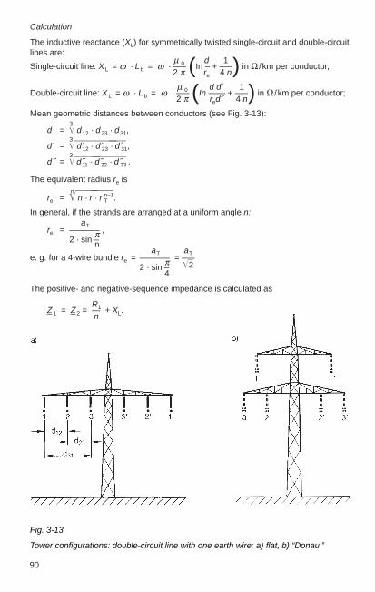
90
Calculation
The inductive reactance (XL) for symmetrically twisted single-circuit and double-circuitlines are:
µ 0 d 1Single-circuit line: X L = ω · L b = ω · —– (In – + —–) in Ω /km per conductor,
2 π re 4 n
µ 0 d d´ 1Double-circuit line: X L = ω · L b = ω · —– (In —— + —–) in Ω /km per conductor;
2 π red˝ 4 n
Mean geometric distances between conductors (see Fig. 3-13):3
d = d 12 · d 23 · d 31,3
d ´ = d 12 · d 23 · d 31,3
d ˝ = d 11 · d 22 · d 33 .
The equivalent radius re isn
re = n · r · r nT
–1.
In general, if the strands are arranged at a uniform angle n:aT
re = ———– ,π2 · sin –naT aT
e. g. for a 4-wire bundle re = ———– = —–π 22 · sin –4
The positive- and negative-sequence impedance is calculated as
R1Z 1 = Z 2 = — + XL.n
Fig. 3-13
Tower configurations: double-circuit line with one earth wire; a) flat, b) “Donau‘”

3
91
Fig. 3-14 and 3-15 show the positive-sequence (and also negative-sequence)reactances of three-phase overhead lines.
Calculation of zero-sequence impedance
The following formulae apply:
Single-circuit line without earth wire Z I0
= R 0 + jX 0,Z 2
asSingle-circuit line with earth wire Z Is0
= Z I0
– 3 ——,Z s
Double-circuit line without earth wire Z II0
= Z I0
+ 3 Z ab,
Z 2asDouble-circuit line with earth wire Z IIs
0= Z II
0– 6 ——,
Z s
For the zero-sequence resistance and zero-sequence reactance included in theformulae, we have:
Zero-sequence resistanceµ0R0 = R L + 3 — ω,8
Zero-sequence reactance
µ0 δ µLX0 = ω –— (3 In 3—— + —–)
2 π rd 2 4 n
Fig. 3-14
Reactance X L (positive phase sequence) of three-phase transmission lines up to72.5 kV, f = 50 Hz, as a function of conductor cross section A, single-circuit lines withaluminium / steel wires, d = mean geometric distance between the 3 wires.
3d = d12 d 23 d 31;
1.85δ = ————— .
1µ0 – ωρ

92
Fig. 3-15
Reactance X L (positive-sequence) of three-phase transmission lines with alumimium/steel wires (“Donau” configuration), f = 50 Hz. Calculated for a mean geometricdistance between the three conductors of one system, at 123 kV: d = 4 m, at 245 kV:d = 6 m, at 420 kV: d = 9.4 m;E denotes operation with one system; D denotes operation with two systems; 1 singlewire, 2 two-wire bundle, a = 0.4 m, 3 four-wire bundle, a = 0.4 m.
Table 3-10
Earth current penetration δ in relation to specific resistance ρ at f = 50 Hz
Nature Alluvial Porous Quartz, impervious Granite, gneissof soil as per: land Limestone Limestone
DIN VDE Clay0228 andCCITT
Marl Sandstone, Clayeyclay schist slate
DIN VDE Moor- — Loam, clay Wet Wet Dry Stony0141 land and soil sand gravel sand or ground
arable land gravel
ρ Ωm 30 50 100 200 500 1 000 3 0001σ = – µS/cm 333 200 100 50 20 10 3.33ρ
δ m 510 660 930 1 320 2 080 2 940 5 100
The earth current penetration δ denotes the depth at which the return current dimin-ishes such that its effect is the same as that of the return current distributed over theearth cross section.

3
93
Compared with the single-circuit line without earth wire, the double-circuit line withoutearth wire also includes the additive term 3 · Z a b, where Z a b is the alternatingimpedance of the loops system a/earth and system b/earth:
µ 0 µ 0 δZ a b = — ω + j ω —– In —— ,
8 2 π d a b
d a b = d´d˝ 3
d ´ = d 12 · d 23 · d 31,3
d ˝ = d 11 · d 22 · d 33 .
For a double-circuit line with earth wires (Fig. 3-16) account must also be taken of:
1. Alternating impedance of the loops conductor/earth and earth wire/earth:
µ 0 µ 0 δ 3Z as = —– ω + j ω —– In —— , das = d1s d 2s d 3s;8 2 π d as
for two earth wires:
6das =
2. Impedance of the loop earth wire /earth:
µ0 µ0 δ µ sZ s = R + —– ω + j ω —– (In – + —–) .8 2 π r 4 n
The values used are for one earth wire n = 1; r = rs; R = R s;Rs
for two earth wires n = 2; r = rs d s1s2; R = —2
d 1s1 d 2s1 d 3s1 d 1s2 d 2s2 d 3s2
Fig: 3-16
Tower configuration: Double-circuit line withtwo earth wires, system a and b

94
Values of the ratio Rs /R– (effective resistance / d. c. resistance) are roughly between1.4 and 1.6 for steel earth wires, but from 1.05 to 1.0 for well-conducting earth wires ofAl /St, Bz or Cu.
For steel earth wires, one can take an average of µ s ≈ 25, while values of about µ s = 5 to 10 should be used for Al /St wires with one layer of aluminium. For Al /St earthwires with a cross-section ratio of 6:1 or higher and two layers of aluminium, and alsofor earth wires or ground connections of Bz or Cu, µ s ≈ 1.
The operating capacitances C b of high-voltage lines of 110 kV to 380 kV lie within arange of 9 · 10–9 to 14 · 10–9 F /km. The values are higher for higher voltages.
The earth wires must be taken into account when calculating the conductor /earthcapacitance. The following values are for guidance only:
Flat tower: CE = (0.6…0.7) · C b.
“Donau” tower: CE = (0.5…0.55) · C b
The higher values of CE are for lines with earth wire, the lower values for those withoutearth wire.
The value of CE for double-circuit lines is lower than for single-circuit lines.
The relationship between conductor /conductor capacitance C g, conductor /earthcapacitance CE and operating capacitance C b is
C b = CE + 3 · C g.
Technical values for transmission wires are given in Section 13.1.4.
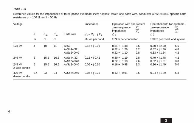
3
95
Table 3-11
Reference values for the impedances of three-phase overhead lines: “Donau” tower, one earth wire, conductor Al /St 240/40, specific earthresistance ρ = 100 Ω · m, f = 50 Hz
Voltage Impedance Operation with one system Operation with two systemszero-sequence X 0 zero-sequence X 0
impedance X 1impedance X 1
d d ab d as Earth wire Z 1 = R 1 + j X 1 Z 10 Z 11
0
m m m Ω / km per cond. Ω / km per conductor Ω / km per cond. and system
123 kV 4 10 11 St 50 0.12 + j 0.39 0.31 + j 1.38 3.5 0.50 + j 2.20 5.6Al/St 44/32 0.32 + j 1.26 3.2 0.52 + j 1.86 4.8Al/St 240/40 0.22 + j 1.10 2.8 0.33 + j 1.64 4.2
245 kV 6 15.6 16.5 Al/St 44/32 0.12 + j 0.42 0.30 + j 1.19 2.8 0.49 + j 1.78 4.2Al/St 240/40 0.22 + j 1.10 2.6 0.32 + j 1.61 3.8
245 kV 6 15.6 16.5 Al/St 240/40 0.06 + j 0.30 0.16 + j 0.98 3.3 0.26 + j 1.49 5.02-wire bundle
420 kV 9.4 23 24 Al/St 240/40 0.03 + j 0.26 0.13 + j 0.91 3.5 0.24 + j 1.39 5.34-wire bundle
96
3.3.5 Three-phase cables
The equivalent diagram of cables can also be represented by Π elements, in the sameway as overhead lines (Fig. 3-11). Owing to the smaller spacings, the inductances aresmaller, but the capacitances are between one and two orders greater than with over-head lines.
When calculating short-circuit currents the positive-sequence operating capacitance isdisregarded. The conductor/earth capacitance is used in the zero phase-sequencesystem.
Calculation of positive and negative phase-sequence impedance
The a.c. resistance of cables is composed of the d.c. resistance (R –) and the com-ponents due to skin effect and proximity effect. The resistance of metal-clad cables(cable sheath, armour) is further increased by the sheath and armour losses.
The d.c. resistance (R –) at 20 °C and A = conductor cross section in mm2 is
18.5 Ωfor copper: R – = —— in ——,
A km
29.4 Ωfor aluminium: R – = —— in ——,
A km
32.3 Ωfor aluminium alloy: R – = —— in ——.
A km
The supplementary resistance of cables with conductor cross-sections of less than 50mm2 can be disregarded (see Section 2, Table 2-8).
The inductance L and inductive reactance X L at 50 Hz for different types of cable anddifferent voltages are given in Tables 3-13 to 3-17.
For low-voltage cables, the values for positive- and negative-sequence impedances aregiven in DIN VDE 0102, Part 2 /11.75.

3
97
Table 3-12
Reference value for supplementary resistance of different kinds of cable in Ω / km, f = 50 Hz
Type of cable cross-section mm2 50 70 95 120 150 185 240 300 400
Plastic-insulated cableNYCY1) 0.6/1 kV — 0.003 0.0045 0.0055 0.007 0.0085 0.0115 0.0135 0.018NYFGbY2) 3.5/6 kV to 5.8/10 kV — 0.008 0.008 0.0085 0.0085 0.009 0.009 0.009 0.009NYCY2) — —- 0.0015 0.002 0.0025 0.003 0.004 0.005 0.0065
Armoured lead-covered cableup to 36 kV 0.010 0.011 0.011 0.012 0.012 0.013 0.013 0.014 0.015
Non-armoured aluminium-covered cable up to 12 kV 0.0035 0.0045 0.0055 0.006 0.008 0.010 0.012 0.014 0.018
Non-armoured single-core cable(laid on one plane, 7 cm apart)up to 36 kVwith lead sheath 0.012 0.012 0.012 0.012 0.012 0.012 0.012 0.012 0.012with aluminium sheath 0.005 0.005 0.005 0.005 0.005 0.005 0.005 0.005 0.005
Non-armoured single-core oil-filled cable with lead sheath(bundled) 123 kV — — 0.009 0.009 0.009 0.0095 0.0095 0.010 0.0105(laid on one plane,18 cm apart) 245 kV — — — — 0.0345 0.035 0.035 0.035 0.035
Three-core oil-filled cable,armoured with lead sheath, 36 to 123 kV 0.010 0.011 0.011 0.012 0.012 0.013 0.013 0.014 0.015non-armoured with 36 kV — 0.004 0.006 0.007 0.009 0.0105 0.013 0.015 0.018aluminium sheath, 123 kV — — 0.0145 0.0155 0.0165 0.018 0.0205 0.023 0.027
1) With NYCY 0.6/1 kV effective cross section of C equal to half outer conductor. 2) With NYFGbY for 7.2 /12 kV, at least 6 mm2 copper.

98
Table 3-14
Hochstädter cable (H cable) with metallized paper protection layer, inductive reactanceX L (positive phase sequence) per conductor at f = 50 Hz
Number of cores and U = 7.2 kV U = 12 kV U = 17.5 kV U = 24 kV U = 36 kVconductor cross-section X L X L X L X L X L
mm2 Ω / km Ω / km Ω / km Ω / km Ω / km
3 × 10 re 0.134 0.143 — — —3 × 16 re or se 0.124 0.132 0.148 — —3 × 25 re or se 0.116 0.123 0.138 0.148 —
3 × 35 re or se 0.110 0.118 0.13 0.14 0.1543 × 25 rm or sm 0.111 0.118 — — —3 × 35 rm or sm 0.106 0.113 — — —
3 × 50 rm or sm 0.10 0.107 0.118 0.126 0.1383 × 70 rm or sm 0.096 0.102 0.111 0.119 0.133 × 95 rm or sm 0.093 0.098 0.107 0.113 0.126
3 × 120 rm or sm 0.090 0.094 0.104 0.11 0.1213 × 150 rm or sm 0.088 0.093 0.10 0.107 0.1163 × 185 rm or sm 0.086 0.090 0.097 0.104 0.113
3 × 240 rm or sm 0.085 0.088 0.094 0.10 0.1083 × 300 rm or sm 0.083 0.086 0.093 0.097 0.105
Table 3-13
Armoured three-core belted cables1), inductive reactance X L (positive phasesequence) per conductor at f = 50 HZ
Number of cores U = 3.6 kV U = 7.2 kV U = 12 kV U = 17.5 kV U = 24 kVand conductor X L X L X L X L X L
cross-sectionmm2 Ω / km Ω / km Ω / km Ω / km Ω / km
3 × 6 0.120 0.144 — — —3 × 10 0.112 0.133 0.142 — —3 × 16 0.105 0.123 0.132 0.152 —
3 × 25 0.096 0.111 0.122 0.141 0.1513 × 35 0.092 0.106 0.112 0.135 0.1423 × 50 0.089 0.10 0.106 0.122 0.129
3 × 70 0.085 0.096 0.101 0.115 0.1223 × 95 0.084 0.093 0.098 0.110 0.1173 × 120 0.082 0.091 0.095 0.107 0.112
3 × 150 0.081 0.088 0.092 0.104 0.1093 × 185 0.080 0.087 0.09 0.10 0.1053 × 240 0.079 0.085 0.089 0.097 0.102
3 × 300 0.077 0.083 0.086 — —3 × 400 0.076 0.082 — — —
1) Non-armoured three-core cables: –15 % of values stated.Armoured four-core cables: + 10 % of values stated.

3
99
Table 3-15
Armoured SL-type cables1), inductive reactance X L (positive phase sequence) perconductor at f = 50 HZ
Number of cores and U = 7.2 kV U = 12 kV U = 17.5 kV U = 24 kV U = 36 kVconductor cross-section X L X L X L X L X L
mm2 Ω / km Ω / km Ω / km Ω / km Ω / km
3 x 6 re 0.171 — — — —3 x 10 re 0.157 0.165 — — —3 x 16 re 0.146 0.152 0.165 — —
3 x 25 re 0.136 0.142 0.152 0.16 —3 x 35 re 0.129 0.134 0.144 0.152 0.1653 x 35 rm 0.123 0.129 — — —
3 x 50 rm 0.116 0.121 0.132 0.138 0.1493 x 70 rm 0.11 0.115 0.124 0.13 0.1413 x 95 rm 0.107 0.111 0.119 0.126 0.135
3 x 120 rm 0.103 0.107 0.115 0.121 0.133 x 150 rm 0.10 0.104 0.111 0.116 0.1263 x 185 rm 0.098 0.101 0.108 0.113 0.122
3 x 240 rm 0.096 0.099 0.104 0.108 0.1183 x 300 rm 0.093 0.096 0.102 0.105 0.113
1) These values also apply to SL-type cables with H-foil over the insulation and for conductors with ahigh space factor (rm/v and r se/3 f). Non-armoured SL-type cables: –15 % of values stated.
Table 3-16
Cables with XLPE insulation, inductive reactance X L (positive phase sequence) perconductor at f = 50 Hz, triangular arrangement
Number of cores and U = 12 kV U = 24 kV U = 36 kV U = 72.5 kV U = 123 kVconductor cross-section X L X L X L X L X L
mm2 Ω / km Ω / km Ω / km Ω / km Ω / km
3 x 1 x 35 rm 0.135 — — — —3 x 1 x 50 rm 0.129 0.138 0.148 — —3 x 1 x 70 rm 0.123 0.129 0.138 — —
3 x 1 x 95 rm 0.116 0.123 0.132 — —3 x 1 x 120 rm 0.110 0.119 0.126 0.151 0.1633 x 1 x 150 rm 0.107 0.116 0.123 0.148 0.160
3 x 1 x 185 rm 0.104 0.110 0.119 0.141 0.1543 x 1 x 240 rm 0.101 0.107 0.113 0.138 0.1483 x 1 x 300 rm 0.098 0.104 0.110 0.132 0.145
3 x 1 x 400 rm 0.094 0.101 0.107 0.129 0.1383 x 1 x 500 rm 0.091 0.097 0.104 0.126 0.1323 x 1 x 630 rm — — — 0.119 0.129

100
Table 3-17
Cables with XLPE insulation, inductive reactance X L (positive phase sequence) perconductor at f = 50 Hz
Number of cores and U = 12 kVconductor cross-section X L
mm2 Ω / km
3 x 50 se 0.1043 x 70 se 0.1013 x 95 se 0.0943 x 120 se 0.0913 x 150 se 0.0883 x 185 se 0.0853 x 240 se 0.082
Zero-sequence impedance
It is not possible to give a single formula for calculating the zero-sequence impedanceof cables. Sheaths, armour, the soil, pipes and metal structures absorb the neutralcurrents. The construction of the cable and the nature of the outer sheath and of thearmour are important. The influence of these on the zero-sequence impedance is bestestablished by asking the cable manufacturer. Dependable values of the zero-sequenceimpedance can be obtained only by measurement on cables already installed.
The influence of the return line for the neutral currents on the zero-sequenceimpedance is particularly strong with small cable cross-sections (less than 70 mm2). Ifthe neutral currents return exclusively by way of the neutral (4th) conductor, then
R 0L = R L + 3 · R neutral, X 0L ≈ (3,5…4.0)xL
The zero-sequence impedances of low-voltage cables are given in DIN VDE 0102,Part 2 / 11.75.
Capacitances
The capacitances in cables depend on the type of construction (Fig. 3-17).
With belted cables, the operating capacitance Cb is Cb = CE + 3 Cg, as for overheadtransmission lines. In SL and Hochstädter cables, and with all single-core cables, thereis no capacitive coupling between the three conductors; the operating capacitance Cbis thus equal to the conductor/earth capacitance CE. Fig. 3-18 shows the conductor /earth capacitance CE of belted three-core cables for service voltages of 1 to 20 kV, asa function of conductor cross-section A. Values of CE for single-core, SL and H cablesare given in Fig. 3-19 for service voltages from 12 to 72.5 kV.
Fig. 3-17
Partial capacitances for different types of cable:a) Belted cable, b) SL and H type cables, c) Single-core cable
a) b) c)
Cb = CE = 3 Cg Cg = 0 Cb = CE Cg = 0 Cb = CE
CE ≈ 0,6 Cb

3
101
Fig. 3-18
Conductor /earth capacitance CE of belted three-core cables as a function of conductorcross-section A. The capacitances of 1 kV cables must be expected to differconsiderably.
Fig. 3-19
Conductor/earth capacitance CE of single-core, SL- and H-type cables as a function ofconductor cross-section A.
The conductor /earth capacitances of XLPE-insulated cables are shown in Tables 3-18and 3-19.

102
3.3.6 Busbars in switchgear installations
In the case of large cross-sections the resistance can be disregarded.Average values for the inductance per metre of bus of rectangular section and arrangedas shown in Fig. 3-20 can be calculated from
π · D + bL´ = 2 · [In (2 ————–) + 0.33] · 10–7 in H /m.π · B + 2 b
Table 3-18
Cables with XLPE insulation, conductor /earth capacitance C E per conductor
Number of cores and U = 12 kV U = 24 kV U = 36 kV U = 72.5 kV U = 123 kVconductor cross-section C E C E C E C E C Emm2 µF/km µF/km µF/km µF/km µF/km
3 x 1 x 35 rm 0.239 — — — —3 x 1 x 50 rm 0.257 0.184 0.141 — —3 x 1 x 70 rm 0.294 0.202 0.159 — —3 x 1 x 95 rm 0.331 0.221 0.172 — —3 x 1 x 120 rm 0.349 0.239 0.184 0.138 0.1103 x 1 x 150 rm 0.386 0.257 0.196 0.147 0.1153 x 1 x 185 rm 0.423 0.285 0.208 0.156 0.1253 x 1 x 240 rm 0.459 0.312 0.233 0.165 0.1353 x 1 x 300 rm 0.515 0.340 0.251 0.175 0.1453 x 1 x 400 rm 0.570 0.377 0.276 0.193 0.1553 x 1 x 500 rm 0.625 0.413 0.300 0.211 0.1653 x 1 x 630 rm — — — 0.230 0.185
Here:D Distance between centres of outer main conductor, b Height of conductor, B Width of bars of one phase,L´ Inductance of one conductor in H/m.
To simplify calculation, the value for L´ for common busbar cross sections andconductor spacings has been calculated per 1 metre of line length and is shown by thecurves of Fig. 3-20. Thus,
X = 2 π · f · L´ · l
Table 3-19
Cables with XLPE insulation, conductor /earth capacitance C E per conductor
Number of cores and U = 12 kVconductor cross-section C Emm2 µF/km
3 x 50 se 0.2763 x 70 se 0.3123 x 95 se 0.3493 x 120 se 0.3683 x 150 se 0.4043 x 185 se 0.4413 x 240 se 0.496

3
103
3.4 Examples of calculation
More complex phase fault calculations are made with computer programs (Calpos®).See Section 6.1.5 for examples.
When calculating short-circuit currents in high-voltage installations, it is often sufficientto work with reactances because the reactances are generally much greater inmagnitude than the effective resistances. Also, if one works only with reactances in thefollowing examples, the calculation is on the safe side. Corrections to the reactancesare disregarded.
The ratios of the nominal system voltages are taken as the transformer ratios. Insteadof the operating voltages of the faulty network one works with the nominal system
Example:
Three-phase busbars 40 m long, each conductor comprising three copper bars 80 mm × 10 mm (A = 2400 mm2), distance D = 30 cm, f = 50 Hz. According to the curve,L´ = 3.7 · 10–7 H/m; and so
X = 3.7 · 10–7 H /m · 314 s–1 · 40 m = 4.65 m Ω.
The busbar arrangement has a considerable influence on the inductive resistance.
The inductance per unit length of a three-phase line with its conductors mounted onedge and grouped in phases (Fig. 3-20 and Fig. 13-2a) is relatively high and can beusefully included in calculating the short-circuit current.
Small inductances can be achieved by connecting two or more three-phase systems inparallel. But also conductors in a split phase arrangement (as in Fig. 13-2b) yield verysmall inductances per unit length of less than 20 % of the values obtained with themethod described. With the conductors laid flat side by side (as in the MNS system) theinductances per unit length are about 50 % of the values according to the method ofcalculation described.
Fig. 3-20
Inductance L´ ofbusbars of rectangularcross section

104
voltage. It is assumed that the nominal voltages of the various network components arethe same as the nominal system voltage at their respective locations. Calculation isdone with the aid of the %/ MVA system.
Example 1
To calculate the short-circuit power S"k, the peak short-circuit current i p and thesymmetrical short-circuit breaking current Ia in a branch of a power plant station servicebusbar. This example concerns a fault with more than one infeed and partly commoncurrent paths. Fig. 3-21 shows the equivalent circuit diagram.
For the reactances of the equivalent circuit the formulae of Table 3-4 give:
1.1 · 100 110Network reactance xQ = ———— = ——– = 0.0138 %/MVA,S kQ 8000
uK 13Transformer 1 xT1 = —— = —— = 0.1300 %/MVA,
S rT1 100x d 11.5
Generator xG = —— = —— = 0.1227 %/MVA,S rG 93.7uK 7
Transformer 2 xT2 = —— = —— = 0.8750 %/MVA,S rT2 8IrM/Istart 1
Induction motor xM1 = ——— · 100 = ———— · 100 = 7.4349 %/MVA,S rM 5 · 2.69
IrM/Istart 1Induction- xM2 = ——— · 100 = —————– · 100 = 5.4348 %/MVA.motor group S rM 5 · 8 · 0.46
For the location of the fault, one must determine the total reactance of the network. Thisis done by step-by-step system transformation until there is only one reactance at theterminals of the equivalent voltage source: this is then the short-circuit reactance.
Calculation can be made easier by using Table 3-20, which is particularly suitable forcalculating short circuits in unmeshed networks. The Table has 9 columns, the first ofwhich shows the numbers of the lines. The second column is for identifying the parts andcomponents of the network. Columns 3 and 4 are for entering the calculated values.The reactances entered in column 3 are added in the case of series circuits, while thesusceptances in column 4 are added for parallel configurations.Columns 6 to 9 are for calculating the maximum short-circuit current and thesymmetrical breaking current.To determine the total reactance of the network at the fault location, one first adds thereactances of the 220 kV network and of transformer 1. The sum 0.1438 % /MVA is incolumn 3, line 3.The reactance of the generator is then connected in parallel to this total. This is doneby forming the susceptance relating to each reactance and adding the susceptances(column 4, lines 3 and 4).The sum of the susceptances 15.1041 % /MVA is in column 4, line 5. Taking thereciprocal gives the corresponding reactance 0.0662 % /MVA, entered in column 3, line5. To this is added the reactance of transformer 2. The sum of 0.9412 % /MVA is incolumn 3, line 7.The reactances of the induction motor and of the induction motor group must then beconnected in parallel to this total reactance. Again this is done by finding thesusceptances and adding them together.

3
105
The resultant reactance of the whole network at the site of the fault, 0.7225% /MVA, isshown in column 3, line 10. This value gives
1.1 · 100 % 1.1 · 100 %S k = ————— ———————— = 152 MVA, (column 5, line 10).
x k 0.7225 % /MVA
To calculate the breaking capacity one must determine the contributions of theindividual infeeds to the short-circuit power S k.
The proportions of the short-circuit power supplied via transformer 2 and by the motorgroup and the single motor are related to the total short-circuit power in the same wayas the susceptances of these branches are related to their total susceptance.
Contributions of individual infeeds to the short-circuit power:
0.1345Contribution of single motor S kM1 = ——— · 152 = 14.8 MVA,1.381
0.184Contribution of motor group S kM2 = ——— · 152 = 20.3 MVA,1.381
1.0625Contribution via transformer 2 S kT2 = ——— · 152 = 116.9 MVA.1.381
The proportions contributed by the 220 kV network and the generator are foundaccordingly.
8.150Contribution of generator S kG = ——— · 116.9 = 63.1 MVA,15.104
6.954Contribution of 220 kV network S kQ = ——— · 116.9 = 53.8 MVA.15.104
The calculated values are entered in column 5. They are also shown in Fig. 3-21b.
To find the factors µ and q
When the contributions made to the short-circuit power S k by the 220 kV network, thegenerator and the motors are known, the ratios of S k /S r are found (column 6). Thecorresponding values of µ for t v = 0.1 s (column 7) are taken from Fig. 3-5.Values of q (column 8) are obtained from the ratio motor rating / number of pole pairs(Fig. 3-6), again for t v = 0.1 s.
Single motorS kM1 14.8 motor rating 2.3—— = —— = 5.50 → µ = 0.74 —————— = —– = 1.15 → q = 0.59S rM1 2.69 no. pole pairs 2
Motor groupS kM2 20.3 motor rating 0.36—— = —–—— = 5.52 → µ = 0.74 —————— = —–– = 1.12 → q = 0.32SrM2 8 · 0.46 no. pole pairs 3
S kG 63.1Generator —— = —–– = 0.67 → µ = 1
S rG 93.7
For the contribution to the short-circuit power provided by the 220 kV network, µ = 1,see Fig. 3-5, since in relation to generator G 3 it is a far-from-generator fault.

106
Contributions of individual infeeds to the “breaking capacity”
The proportions of the short-circuit power represented by the 220 kV network, thegenerator and the motors, when multiplied by their respective factors µ and q, yield thecontribution of each to the breaking capacity, column 9 of Table 3-20.
Single motor SaM1 = µ q S kM1 = 0.74 · 0.59 · 14.8 MVA = 6.5 MVA
Motor group SaM2 = µ q S kM2 = 0.74 · 0.32 · 20.3 MVA = 4.8 MVA
Generator SaG = µ S kG = 1 · 63.1 MVA = 63.1 MVA
220 kV network SaQ = µ S kQ = 1 · 53.8 MVA = 53.8 MVA
The total breaking capacity is obtained as an approximation by adding the individualbreaking capacities. The result Sa = 128.2 MVA is shown in column 9, line 10.
Table 3-20
Example 1, calculation of short-circuit current
1 2 3 4 5 6 7 8 9Component x 1 S k S k /Sr µ q Sa
x% /MVA MVA/% MVA (0.1s) (0.1s) MVA
1 220 kV network 0.0138 — 53.8 — 1 — 53.82 transformer 1 0.1300 — — — — — —3 1 and 2 in series 0.1438 → 6.9541 — — — — —4 93.7 MVA generator 0.1227 → 8.1500 63.1 0.67 1 — 63.15 3 and 4 in parallel 0.0662 ← 15.1041 — — — — —6 transformer 2 0.8750 — — — — — —7 5 and 6 in series 0.9412 → 1.0625 116.9 — — — —8 induction motor
2.3 MW/ 2.69 MVA 7.4349 → 0.1345 14.8 5.50 0.74 0.59 6.59 motor group
Σ = 3.68 MVA 5.4348 → 0.1840 20.3 5.52 0.74 0.32 4.810 fault location
7, 8 and 9 in parallel 0.7225 ← 1.3810 152.0 — — — 128.2
At the fault location:
S k 152.0 MVA I k = ——–— = ————— = 14.63 kA,
3 · Un 3 · 6.0 kV
I p = κ · 2 · I k = 2.0 · 2 · 14.63 kA = 41.4 kA (for κ = 2.0),
S a 128.2 MVA I a = ——–— = ————— = 12.3 kA.
3 · Un 3 · 6.0 kV
Example 2
Calculation of the phase-to-earth fault current I k1.
Find I k1 at the 220 kV busbar of the power station represented by Fig. 3-22.
Calculation is made using the method of symmetrical components. First find thepositive-, negative- and zero-sequence reactances X1, X 2 and X 0 from the networkdata given in the figure.

3
107
Fig. 3-21
a) Circuit diagram, b) Equivalent circuit diagram in positive phase sequence withequivalent voltage source at fault location, reactances in %/MVA: 1 transformer 1,2 transformer 2, 3 generator, 4 motor, 5 motor group, 6 220 kV network, 7 equivalentvoltage at the point of fault.
Zero-sequence reactances (index 0)
A zero-sequence system exists only between earthed points of the network and thefault location. Generators G1 and G 2 and also transformer T1 do not thereforecontribute to the reactances of the zero-sequence system.
Positive-sequence reactances (index 1)
1Overhead line X1L = 50 · 0.32 Ω · – = 8 Ω2
1.1 · (220 kV)2220 kV network X = 0.995 · —————–— = 6.622 Ω
8000 MVA(21 kV)2
Power plant unit XG = 0.14 · ———— = 0.494 Ω125 MVA
(220 kV)2XT = 0.13 · ———— = 48.4 Ω
130 MVA
XKW = KKW (ü2r · XG + XT)
1.1KKW = ——————————1 + (0.14 – 0.13) · 0.6
220XKW = 1.093 [(——)2· 0.494 + 48.4] Ω = 112.151 Ω
21
At the first instant of the short circuit, x 1 = x 2. The negative-sequence reactances arethus the same as the positive-sequence values. For the generator voltage: UrG = 21 kVwith sin ϕ rG = 0.6, the rated voltages of the transformers are the same as the systemnominal voltages.

108
Overhead lineX 0L = 3.5 · X 1L = 28 Ω2 circuits in parallel
220 kV network X 0Q = 2.5 · X 1Q = 16.555 ΩTransformer T 2 X 0T2
= 0.8 · X 1T · 1.093 = 42.321 Ω
With the reactances obtained in this way, we can draw the single-phase equivalentdiagram to calculate I k1 (Fig. 3-22b).
Since the total positive-sequence reactance at the first instant of the short circuit is thesame as the negative-sequence value, it is sufficient to find the total positive and zerosequence reactance.
Calculation of positive-sequence reactance:1 1 1
— = ——––— + ———— → x 1 = 11.598 Ωx 1 56.076 Ω 14.622 Ω
Calculation of zero-sequence reactance:1 1 1
— = ——––— + ———— → x 0 = 21.705 Ωx 0 42.321 Ω 44.556 Ω
Fig. 3-22
a) Circuit diagram, b) Equivalent circuit diagram in positive phase sequence, negativephase sequence and zero phase sequence with connections and equivalent voltagesource at fault location F for I k1.
With the total positive-, negative- and zero-sequence reactances, we have
1.1 · 3 · Un 1.1 · 3 · 220I k1 = ————–— = —————— = 9.34 kA.
x 1 + x 2 + x 0 44.901

3
109
The contributions to I k1 represented by the 220 kV network (Q) or power station (KW)are obtained on the basis of the relationship
I k1 = I 1 + I 2 + I 0 = 3 · I 1 with I 0 = I 1 = I 2 = 3.11 kA
to right and left of the fault location from the equations:
I k1Q = I 1Q + I 2Q + I 0Q, and I k1KW = I 1KW + I 2KW + I 0KW.
The partial component currents are obtained from the ratios of the respectiveimpedances.
56.08I 1Q = I 2Q = 3.11 kA · ——— = 2.47 kA70.70
42.32I 0Q = 3.11 kA · ——— = 1.51 kA86.88
I 1KW = 0.64 kA
I 0KW = 1.60 kA
I k1Q = (2.47 + 2.47 + 1.51) kA = 6.45 kA
I k1KW = (0.641 + 0.64 + 1.60) kA = 2.88 kA
Example 3
The short-circuit currents are calculated with the aid of Table 3-2.
1.1 · (0.4)2
20 kV network: x1Q = 0.995 ————— = 0.0007 Ω250
r1Q ≈ 0.1 x1Q = 0.00007 Ω
(0.4)2
Transformer: x1T = 0.058 ——— = 0.0147 Ω0.63
(0.4)2
r1T = 0.015 ——— = 0.0038 Ω0.63
x 0T = 0.95 · x 1T = 0.014 Ωr0T ≈ r1T = 0.0038 Ω
Cable: x1L = 0.08 · 0.074 = 0.0059 Ωr1L20 = 0.08 · 0.271 = 0.0217 Ωr1L80 = 1.24 · r 1L20 = 0.0269 Ωx 0L ≈ 7.36 · x 1L = 0.0434 Ωr0L20 ≈ 3.97 · r 1L20 = 0.0861 Ωr0L80 = 1.24 · r 0L20 = 0.1068 Ω
Maximum and minimum short-circuit currents at fault location F 1
a. Maximum short-circuit currents
Z 1 = Z 2 = (0.0039 + j 0.0154) Ω; Z 0 = (0.0038 + j 0.0140) Ω1.0 · 0.4I k3 = —————– kA = 14.5 kA
3 · 0.0159
3I k2 = —– I k3 = 12.6 kA2
3 · 1.0 · 0.4I k1 = —–——–—— kA = 15.0 kA.0.0463

110
Table 3-21
Summary of results
Fault Max. short-circuit currents Min. short-circuit currentslocation 3p 2p 1p 3p 2p 1p
kA kA kA kA kA kA
Fault location F 1 14.5 12.6 15.0 13.8 12.0 14.3Fault location F 2 6.9 6.0 4.0 6.4 5.5 3.4
The breaking capacity of the circuit-breakers must be at least 15.0 kA or 6.9 kA.Protective devices must be sure to respond at 12 kA or 3.4 kA. These figures relate tofault location F1 or F2.
b. Minimum short-circuit currents
The miminum short-circuit currents are calculated with c = 0.95.
Maximum and minimum short-circuit currents at fault location F 2
a. Maximum short-circuit currents
Z 1 = Z 2 = (0.0265 + j 0.0213) Ω; Z 0 = (0.0899 + j 0.0574) Ω1.0 · 0.4I k3 = —————– kA = 6.9 kA
3 · 0.0333
3I k2 = —– I k3 = 6.0 kA2
3 · 1.0 · 0.4I k1 = —–——–—— kA = 4.0 kA.0.1729
b. Minimum short-circuit currents
The minimum short-circuit currents are calculated with c = 0.95 and a temperature of80 °C.
Fig. 3-23
a) Circuit diagram oflow-voltage network,b) Equivalent diagram incomponent systems andconnection for single-phase fault

3
111
Examples of use Networks of limited Overhead-line Cable networks High-voltage networksextent, power plant networks 10…230 kV system (123 kV) to 400 kVauxiliaries 10…123 kV e. g. in towns (protective multiple
earthing in I. v. network)
Between system Capacitances, (inst. trans- Capacitances, Capacitances, (Capacitances),and earth are: former inductances) Suppression coils Neutral reactor Earth conductor
Z 0 / Z 1 1/ jωCE very high resistance inductive: 4 to 60 2 to 4——— resistive: 30 to 60Z 1
Current at fault site with Ground-fault Residual ground- Ground-fault current I k1
single-phase fault current fault currentCalculation (approximate) I E (capacitive) I R
I E ≈ j 3 ω CE · E 1 I R ≈ 3 ω CE(δ + jν) E 1
δ = loss angleν = interference
3.5 Effect of neutral point arrangement on fault behaviour in three-phase high-voltage networks above 1 kV
Table 3-22
Arrangement of neutral isolated with arc current-limiting low-resistance earthpoint suppression coil R or X
c · UnE1 = —–— = E ˝
3
3 E 1I k1 = I R ≈ —–———–——
j (X 1 + X 2 + X 0)
I k1 3 X 1 3—– = —–——— = —–—––—I k3 2 X 1 + X 0 2 + X 0 /X1 (continued)

112 Table 3-22 (continued)
Arrangement of neutral isolated with arc current-limiting low-resistance earthpoint suppression coil R or X
I k2 / I k3 ICE / I k3 IR / I k3 inductive: 0.05 to 0.5 0.5 to 0.75resistive: 0.1 to 0.05
U LEmax /Un ≈ 1 1 to (1.1) inductive: 0.8 to 0.95 0.75 to 0.80resistive: 0.1 to 0.05
U 0max /Un ≈ 0.6 0.6 to 0.66 inductive: 0.42 to 0.56 0.3 to 0.42resistive: 0.58 to 0.60
Voltage rise in yes yes no nowhole network
Duration of fault 10 to 60 min 10 to 60 min < 1 s < 1 sPossible short-time earthing with subsequent selectivedisconnection by neutral current (< 1 s)
Ground-fault arc Self-quenching Self-quenching Partly self-quenching Sustainedup to several A usually sustained
Detection Location by disconnection, ground-fault wiping-contact Selective disconnection by Short-circuitrelay, wattmeter relay. (With short-time earthing: dis- neutral current (or short- protectionconnection by neutral current) circuit protection)
Risk of double earth fault yes yes slight no
Means of earthing Earth electrode voltage UE < 125 V Earth electrode voltage U E > 125 V permissibleDIN VDE 0141 Touch voltage 65 V Touch voltages 65V
Measures against interfer- Generally not Not necessary Overhead lines: possibly required if approaching overence with communication necessary a considerable distancecircuits Cables: generally not necessaryDIN VDE 0228 needed only with railway block lines

4
113
4 Dimensioning switchgear installations
4.1 Insulation rating
Rating the dielectric withstand of equipment is based on the expected dielectricstresses. This is a combination of the stress caused by the power-frequency continuousvoltage and the stress caused by the mostly short-term overvoltages. The insulationcoordination for power-frequency continuous voltages ≤ 1 kv is based on DIN VDE0110 and DIN VDE 0109 (currently still in draft form). In the case of voltages > 1 kV thespecifications in DIN EN 60071-1 (VDE 0111 Part l) and the application guide in DIN EN 60071-2 (VDE 0111 Part 2) apply.
The insulation coordination is defined in DIN EN 60071-1 (VDE 0111 Part l) as theselection of the dielectric withstand required for equipment that is to be used at aspecific site in a network. This process requires knowledge of the operationalconditions in the network and the planned overvoltage protection devices, and theprobability of an insulation fault on equipment which can be accepted under economicand operational aspects.
The “dielectric withstand” can be defined here by a rated insulation level or by astandard insulation level. A rated insulation level is considered any combination ofstandard withstand voltages, a standard insulation level is considered a rated insulationlevel whose standard withstand voltages in combination with the associated highestvoltage for equipment Um are recommended in selection tables (Tables 4-1 and 4-2).These combinations are based on operational experience with networks that meet theIEC standard. However, they are not associated with specific operational conditions.
When discussing insulation, a distinction is made between external and internalinsulation. External insulation consists of clearances in air and the dielectricallystressed surfaces of solid insulation. It is exposed to atmospheric and other effectssuch as pollution, moisture, animals etc. It can be either protected (indoor) orunprotected (outdoor). The internal insulation can be solid, fluid or gaseous insulationmaterial. It is protected against atmospheric and other external effects.
There is also a distinction between self-restoring and non-self-restoring insulation, butonly with reference to the response of the insulation under dielectric tests. Insulation isconsidered self-restoring if its insulation properties are restored after a breakdownduring the test.
The power frequency voltages and the overvoltages acting on an insulation or anovervoltage protection device can be classified by causes and processes into thefollowing categories:– power frequency continuous voltages resulting from normal system operation– temporary overvoltages (power frequency) resulting from earth faults, switching
operations (e.g. load shedding, resonances, ferroresonance or similar)– slow-front overvoltages resulting from switching operations or direct lightning strikes
at great distance, with rise times between 20 µs and 5000 µs and times to half-valueup to 20 ms
114
– fast-front overvoltages resulting from switching operations or lightning strikes withrise times between 0.1 µs and 20 µs and times to half-value up to 300 µs
– very fast-front overvoltages resulting from faults or switching operations in gas-insulated switchgear with rise times below 0.1 µs and superimposed oscillations inthe frequency range of 30 kHz to 100 MHz with a total duration of 3 ms
– combined overvoltages, primarily between conductors and at open breaker gaps.
It is assumed that within one of these categories the different voltage characteristicscan have the same dielectric effects on the insulation or can be converted to a specifiedcharacteristic. The following standardized voltage shapes are defined as representativevoltage characteristics for the above categories – except for the very fast-frontovervoltages:– standard short-duration power-frequency voltage with a frequency between 48 Hz
and 62 Hz and a duration of 60 s – standard switching impulse voltage; a voltage pulse with a rise time of
250 µs and a time to half-value of 2500 µs – standard lightning impulse voltage; a voltage pulse with a rise time of
1.2 µs and a time to half-value of 50 µs– combined standard switching impulse voltage; two simultaneous voltage impulses of
opposite polarity
Insulation coordination procedure
The procedure in accordance with DIN EN 60071-1 (VDE 0111 Part l) in its current formrequires basic knowledge of the physical processes, the operating conditions and thedielectric response of the equipment with its application. Fig. 4-1 shows the predictedprocess sequence as a flow chart.
The starting point of the coordination procedure is the system analysis, which shoulddetermine what voltage stresses can be expected under operational conditions,possibly with the aid of switching tests in the system. This should also includeovervoltage protection devices. The investigations for all ranges of service voltagesmust include the stress on the conductor-earth insulation, the stress between theconductors and the longitudinal stress on the switching apparatus. The overvoltagesmust be assessed by peak value, curve and rate of occurrence and classified under thecorresponding (curve) categories. The results of the system analysis will include peakvalues and rate of occurrence of voltage stress in the following categories: short-duration power-frequency voltage, switching impulse voltage, lightning impulse voltageetc. They are shown in the flow chart (Fig. 4-1) as Urp, representative voltages andovervoltages.

4
115
Fig. 4-1
Flow chart for determining the rated insulation level or the standard insulation level
Values and classification of stressingvoltages, rate of occurrence of stressingvoltage values, protection level of theovervoltage protection devices
System analysis
Coordination factor Kc Performance criteria Insulation characteristic
(statistical distribution) Inaccuracy of input data
Urp Representative voltages and overvoltages
Atmospheric correction factor Ka
Safety factor Ks Test assembly of equipment Number of devices in service Spread of production Quality of the installation Aging in operation
Test conversion factor Kt
Comparison with standard withstandvoltages
Selection of insulation with reference to the performance criterion
Selection of standard withstand voltages Uw
Application of factors for consideration of the differencesbetween type-testing conditionsand actual operating conditions
Ucw coordinating withstand voltages
Urw required withstand voltages
Rated insulation level:combination of Uw values
Framed field with required data
Framed field with required actions
Framed field with results

116
The performance criterion is of fundamental importance for the next step. This is givenin the form of a permissible fault rate, how often a device at that specific point on thesystem may be subject to insulation faults caused by the representative voltages andovervoltages (Urp). The next step is to determine the lowest values of the withstandvoltages, the equipment must satisfy to meet the Performance criterion. They arereferred to as coordinating withstand voltages (Ucw). The difference between the valueof a representative overvoltage and that of the associated coordinating withstandvoltage is characterized by the coordination factor Kc, which must be multiplied by therepresentative overvoltage to derive the coordinating withstand voltage.
To determine the coordination factor Kc with transient overvoltages, a deterministicprocedure, a statistical procedure or a combination of the two may be selected. Inputquantities are the probability function of the overvoltages (Urp), as the result of thesystem analysis on one hand and on the other hand, the disruptive dischargeprobability distribution of the insulation in question. The coordination factor should alsoinclude an allowance for any inaccuracies in the input quantities.
The deterministic procedure is used in cases where, for example, with an internalinsulation only a conventional withstand voltage (Pw = 100%) can be assumed and thisis also protected by a surge arrester. The deterministic layout is also used in the caseof overvoltage protection of equipment linked to overhead lines, when the differencebetween an existing statistical withstand-voltage characteristic (Pw = 90%) and theassumed conventional withstand voltage of the same insulation configuration is takeninto consideration by the coordination factor Kc. The deterministic procedure does notleave a defined fault rate for the equipment during operation.
In the statistical procedure, the overvoltage and disruptive discharge probability areavailable as statistical data and can be combined simultaneously, e.g. with the MonteCarlo method. This calculation must be done for the different kinds of insulationconcerned and for different system configurations to determine the total non-availabilityof a device or an installation.
An insulation can therefore only be economically optimized by statistical design whenthe downtime expenses are defined for specific fault types. Therefore, the morecomplex statistical procedure can only be applied in very specific cases, such as thedesign of switchgear installations for the maximum transmission voltages.
The next step leads from the coordinating withstand voltages (Ucw) to the requiredwithstand voltages (Urw). Two correction factors are used here. The atmosphericcorrection factor Ka primarily corrects for the air pressure at the set-up area of theequipment with external insulation, i.e. primarily the altitude. Ambient temperature andhumidity have the tendency of acting against each other in their influence on thewithstand voltage. The atmospheric conditions generally do not influence the internalinsulation.

4
117
The atmospheric correction factor is calculated as follows:
H: altitude in metresm: an exponent that for clean insulators is different from 1 only with switching impulses
and that depending on the voltage and geometry of the insulation is to be taken asa guidance value from characteristics (cf. DlN EN 60071-2, Fig. 9!). In the case ofcontaminated insulators, m is in the range between 0.5 and 0.8 for the power-frequency withstand voltage test.
The safety factor Ks considers the number of all other influences that could result in adifference between the equipment in operation and the test object in the type test.
These are:– aging caused by thermal, dielectric, chemical and mechanical stresses, – spread caused by manufacturing conditions,– spread caused by installation, such as changes in the connection technology, parallel
loading or numerous devices in operation in comparison to type-testing one singlespecimen only, etc.
Recommended safety factors are:– for internal insulation: Ks = 1.15,– for external insulation: Ks = 1.05.
If the safety factor of 1.15 applicable for internal insulation is also used for externalinsulation, the atmospheric correction is also covered to an operational altitude of 1000 m.
The required withstand voltages (Urw) determined to this point are the minimumwithstand voltages that must be verified for a device by type tests to ensure that thefailure rate predicted in the performance criterion is not exceeded at the operational sitein the system. The required withstand voltages can basically be discarded for each ofthe (curve) categories described above.
The selection tables (Tables 4-1 and 4-2) show standard withstand voltages for the testing of equipment. They show standard voltages for the voltage range I (≤ 245 kV) for testing with short-time power-frequency withstand voltage and withlightning impulse withstand voltage. Voltage range II (> 245 kV) lists standard voltagesfor testing with lightning impulse withstand voltage and switching impulse withstandvoltage.
If the system analysis shows required withstand voltages (Urw) in categories for whichthe selection tables do not have standard values, conversion to one of the categorieslisted there is recommended by using corresponding test conversion factors. Testconversion factors are listed for the two voltage ranges for internal and externalinsulation in DIN EN 60071-2 in Tables 2 and 3.
Ka = emH
——– 8150

118
Table 4-1
Standardized insulation levels in voltage range I (1 kV < Um ≤ 245 kV)as per DIN EN 60071-1 (VDE 0111 Part 1)
Highest voltage Standard short-time Standard for equipment power-frequency lightning impulseUm withstand voltage withstand voltagekV kV kVrms value rms value peak value
3.6 10 2040
7.2 20 4060
12 28 607595
17.5 38 7595
24 50 95125145
36 70 145170
52 95 250
72.5 140 325
123 (185) 450230 550
145 (185) (450)230 550275 650
170 (230) (550)275 650325 750
245 (275) (650)(325) (750)
360 850395 950460 1050
Note: if the values in parentheses are not sufficient to verify that the required conductor-conductorwithstand voltages are met, additional withstand voltage tests will be required.

4
119
Table 4-2
Standardized insulation levels in range II: Um > 245 kVas per DIN EN 60071-1 (VDE 0111 Part 1)
Highest Standard switching-impulse withstand voltage Standard voltage for lightning impulse equipment Longitudinal Conductor-earth Ratio conductor- withstand Um insulation (note 1) conductor to voltagekV kV kV conductor-earth kVrms value peak value peak value peak value peak value
300 750 750 1.50 850950
750 850 1.50 9501 050
362 850 850 1.50 9501 050
850 950 1.50 1 0501 175
420 850 850 1.60 1 0501 175
950 950 1.50 1 1751 300
950 1 050 1.50 1 3001 425
525 950 950 1.70 1 1751 300
950 1 050 1.60 1 3001 425
950 1 175 1.50 1 4251 550
765 1 175 1 300 1.70 1 6751 800
1 175 1 425 1.70 1 8001 950
1 175 1 550 1.60 1 9502 100
Note 1: value of the impulse voltage in combined test.
Note 2: the introduction of Um = 550 kV (instead of 525 kV), 800 kV (instead of 765 kV), 1200 kV andanother value between 765 kV and 1200 kV and the associated standard withstand voltages is beingconsidered.

4.2 Dimensioning of power installations for mechanical andthermal short-circuit strength
(as per DIN EN 60865-1 (November 1994), classification VDE 0103, see alsoIEC 60865-1 (1993-09))1)
Symbols used
A cross section of conductor, with bundle conductors (composite mainconductors): total cross- section
a, l or ls distances in Fig. 4-2
am, as effective main conductor and sub-conductor spacing(Fig. 4-3 and Table 4-3)
a12, a13…a1n geometrical distances between the sub-conductors
k12, k13…k1n correction factors (Fig. 4-3)
E Young’s modulus
f operating frequency of the current circuit
fc relevant characteristic frequency of a main conductor
Fm or Fs electrodynamic force between the main or sub-conductors
I th thermally equivalent short-time current (rms value)
I "k initial symmetrical short-circuit current (rms value)
I "k2 initial symmetrical short-circuit current with phase-to-phase shortcircuit (rms value)
ip, ip2, ip3 peak short-circuit current or cut-off current of current limitingswitchgear or fuses (peak value) with symmetrical short circuit (ip2, ip3: with phase-to-phase or three-phase short circuit)
120
A standardized insulation level from Tables 4-1 and 4-2 must be selected to ensure thatin all test voltage categories the values of the required withstand voltages (Urw) arereached or exceeded.
At least two combinations of rated voltage values are assigned to almost every valuefor the maximum equipment voltage Um. The result of the procedure for the insulationcoordination determines whether the higher or lower values are required, or whetherthe insulation level of another equipment voltage is to be used.
Note:The space available here only allows the basics of the (new) procedure for insulation coordination tobe considered, but not with all the details. Proper application of the procedure is not trivial; it requirescomplete familiarity with the material.This will result in continuing use of the previous procedure in general practice. An exact test will onlybe economically justifiable with specific projects.
1) see KURWIN calculation program in Table 6-2

4
121
J axial planar moment of inertia (Table 1-22)
m factor for thermal effect of the d.c. component (Fig. 4-15)
m’ mass per unit length (kg / m) of a conductor without ice, with bundleconductors: total mass per unit length
n factor for the thermal effect of the a.c. component (Fig. 4-15)
R p02, R ’p02 minimum and maximum stress of the yield point (Table 13-1)
S thr rated short-time current density (rms value) for 1 s
Tk short-circuit duration
Tk1 short-circuit duration with auto-reclosing: duration of the 1st current flow
t number of sub-conductors
Vr orVσ factors for conductor stress
VF ratio of dynamic force to static force on the support
Vr factor for unsuccessful three-phase auto-reclosure in three-phasesystems
Z or Zs moment of resistance of main or sub-conductor during bending(Table 1-22, shown there with W), also called section modulus asused in DIN EN 60865-1 and in KURWIN
α factor for force on support (Table 4-4), dependent on the type ofbusbar and its clamping condition
β factor for main conductor stress (Table 4-4), dependent on the typeof busbar and its clamping condition
γ factor for determining the relevant characteristic frequency of aconductor (Table 4-4)
κ factor for calculating the peak short-circuit current ip as in Fig. 3-1
µ 0 magnetic field constant (4 π · 10–7 H/m)
σ conductor bending stress
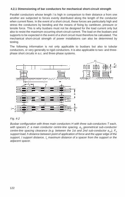
122
4.2.1 Dimensioning of bar conductors for mechanical short-circuit strength
Parallel conductors whose length l is high in comparison to their distance a from oneanother are subjected to forces evenly distributed along the length of the conductorwhen current flows. In the event of a short circuit, these forces are particularly high andstress the conductors by bending and the means of fixing by cantilever, pressure ortensile force. This is why busbars must not be designed for the load current only butalso to resist the maximum occurring short-circuit current. The load on the busbars andsupports to be expected in the event of a short circuit must therefore be calculated. Themechanical short-circuit strength of power installations can also be determined bytesting.
The following information is not only applicable to busbars but also to tubularconductors, or very generally to rigid conductors. It is also applicable to two- and three-phase short circuits in a.c. and three-phase systems.
Fig. 4-2
Busbar configuration with three main conductors H with three sub-conductors T each,with spacers Z: a main conductor centre-line spacing, a1i geometrical sub-conductorcentre-line spacing clearance (e.g. between the 1st and 2nd sub-conductor a12), Fd
support load, h distance between point of application of force and the upper edge of thesupport, l support distance, ls maximum distance of a spacer from the support or theadjacent spacer.
a
a12

4
123
IEC 61660-2 applies to calculations in d.c. systems.
When calculating F with three-phase short-circuits for i p the value 0.93 · i p3 can beused. The factor 0.93 considers the greatest possible load that can be experienced bythe middle conductor of a single-plane configuration in three-phase systems.
The e l e c t r o d y n a m i c f o r c e between the main conductors through which thesame current flows is
µ0 lFm = —— · i p
2 · –2 π a
or as a numerical equation
l lFm = 0.2 · i p22 · – or Fm = 0.173 · i p
23 · –.a a
If the main conductor consists of t single conductors, the electrodynamic force Fs
between the sub-conductors is
µ0 i p2 ls
Fs = —— · (—) · —2 π t as
or as a numerical equation
i p2 ls
Fs = 0.2 · (—) · —t as
Numerical equations with i p in kA, Fm in N and l in the same unit as a.
Effective conductor spacing
As previously mentioned, these equations are strictly speaking only for filament-shapedconductors or in the first approximation for conductors of any cross section, so long astheir distance from one another is significantly greater than the greatest conductordimension. If this condition is not met, e.g. with busbar packets comprising rectangularbar conducters, the individual bars must be divided into current filaments and the forcesbetween them calculated. In this case, the actual effective main conductor spacing am
= a / k1s must be used as the main conductor spacing.
Here, k1s must be taken from Fig. 4-3 where a1s = a and d the total width of the busbarpacket in the direction of the short-circuit force. b – as shown in Fig. 4-3 – is the heightof the busbars perpendicular to the direction of the short-circuit force.
The actual effective sub-conductor clearance is
1 k12 k13 k1n— = —– + —– + … + —–as a12 a13 a1n
For the most frequently used conductor cross sections, as is listed in Table 4-3.

124
Table 4-3
Effective sub-conductor spacing as for rectangular cross sections of bars and U-sections (all quantities in cm) as per DIN EN 60865-1 (VDE 0103)
Configuration Bar Bar width bof bars thickness d 4 5 6 8 10 12 16 20
cm cm cm cm cm cm cm cm cm
0.5 2.0 2.4 2.7 3.3 4.0 — — —1 2.8 3.1 3.4 4.1 4.7 5.4 6.7 8.0
0.5 — 1.3 1.5 1.8 2.2 — — —1 1.7 1.9 2.0 2.3 2.7 3.0 3.7 4.3
1 1.4 1.5 1.6 1.8 2.0 2.2 2.6 3.1
0.5 — 1.4 1.5 1.8 2.0 — — —1 1.74 1.8 2.0 2.2 2.5 2.7 3.2 —
U 60 U 80 U100 U120 U140 U160 U180 U 200
hs = 6 8 10 12 14 16 18 20es = 8.5 10 10 12 14 16 18 20as = 7.9 9.4 10 12 14 16 18 20
Stresses on conductors and forces on supports
The bending stress σ of a busbar must not exceed a specified limit in the event of ashort circuit to avoid excessive stress on the material. In specifying this limit a sustainedbending of the busbar of up to 1 % of the support length has been assumed, becausea deformation of this magnitude is virtually undetectable with the naked eye.
The stress on rigid conductors (busbars) and the forces on the supports are influencedby the oscillation response of the conductors. This in return is dependent on theclamping conditions and the permissible plastic deformation or the natural frequency ofthe conductor. First the upper limit values of the stress are given with consideration tothe plastic deformation, while the following section shows the stresses arising fromconsideration of the oscillation response.

4
125
Fm · lMain conductor stress: σm = Vσ · Vr · β · ———
8 · ZFs · lsSub-conductor stress: σs = Vσ s · Vr · —–——
16 · Z s
When considering the plastic deformation
Vσ · Vr = Vσs · Vr = 1 in two-phase a.c. systems
Vσ · Vr = Vσs · Vr = 1 in three-phase systems without three-phase auto-reclosure
Vσ · Vr = Vσs · Vr = 1.8 in three-phase systems with three-phase auto-reclosure
The resulting conductor stress is a combination of the main and sub-conductor stress:
σ tot = σ m + σ s
The force Fd on each support:
Fd = VF · Vr · α · Fm
with
VF · Vr = 1 for σ tot ≥ 0.8 · R p0.2
0.8 · R p0.2VF · Vr = ———–— for σ tot < 0.8 · R p0.2σ tot
However, in two-phase a.c. systems VF · Vr does not require a value greater than 2 andin three-phase systems no greater than 2.7.If it is unclear whether a busbar can be considered supported or fixed at any specificsupport point, the least suitable case must be taken for rating the busbar and thesupport.
Fig. 4-3
Correction factor k1s
for effective mainconductor and sub-conductor spacingwhere s = 2…t

126
If the condition σ tot ≥ 0.8 · R p0.2 is met, the busbar cannot transfer any forces greaterthan the static forces to the supports, because it will be previously deformed(VF · Vr = 1). However, if σ tot is well below 0.8 · R p0.2, it is recommended that conductorand support loads be determined as follows taking into consideration the relevantcharacteristic frequency of the conductor.
Note to Table 4-4
Continuous beams with multiple supports are continuous bars or tubular conductorsthat have one or more supports along their length. They are secured against horizontaldisplacement at one of the supports. The length to be used in the calculation l is thedistance between the supports, i.e. the length of the spans, not the length of thecontinuous beam.
The factors α and β apply for equal support distances. Support distances are stillconsidered equal when the smallest support distance is at least 0.2 times the value ofthe largest. In this case, end supports are not subject to a higher force than the innersupports. Use the largest support distance for l in the formula.
Table 4-4
Factors α, β and γ as per DIN EN 60865-1 (VDE 0103)
Type of busbar and its clamping condition Force on Main conductor Relevant support stress charcteristic
frequencyFactor α Factor β Factor γ
both sides A: 0.5 1.0 1.57supported B: 0,5
Single-span fixed, A: 0.625 0.73 2.45beam supported B: 0.375
both sides A: 0.5 0.50 3.56fixed B: 0.5
N = 2 A: 0.375 0.73 2.45B: 1.25
N 3 A: 0.4 0.73 3.56B: 1.1
Continuous beamwith multiplesupprts and Nequal orapproximatelyequal supportdistances

4
127
When the characteristic frequencies are considered, the values for Vσ , Vσ s, VF and Vr
to calculate the main conductor and sub-conductor stresses and the forces on supportsusing the formulae given above may be taken from Fig. 4-4, 4-5 and 4-6 (as per DIN EN60865-1 (VDE 0103)). At short-circuit durations Tk or Tk1 of 0.1 s or less the actualstresses and forces may be considerably less than the calculated values with fc ≤ f.
Stresses on conductors and forces on supports with respect to conductor oscillation
If the characteristic frequency fc of a conductor is taken into account, lower values forstresses on conductors and forces on supports may be derived than if the characteristicfrequency is not considered. If higher values are found here, they are not relevant.
The characteristic frequency of a conductor is
γ E · Jfc = — ———l 2 m´
For determining the characteristic frequency of a main conductor, the factor γ is useddepending on the clamping conditions in Table 4-4. If the main conductor consists ofseveral sub-conductors, J and m’ refer to the main conductor. The data of a sub-conductor should be used for J and m’ if there are no stiffening elements along thelength of the support distance. In the event that stiffening elements are present, seeDIN EN 60865-1 and IEC 60865-1 for additional information. The installation position ofthe bar conductor with reference to the direction of the short-circuit force must beconsidered for the axial planar moment of inertia. γ = 3.56 and l for the distancebetween two stiffening elements must be used for calculating the sub-conductorstresses.
Fig. 4-4 Factor VF to determine theforces on supports
Fig. 4-5
Factors Vσ and Vσ s todetermine the conductorstresses
1: κ ≥ 1.602: κ = 1.403: κ = 1.254: κ = 1.105: κ = 1.00
κ values for Fig. 4-4 and 4-5
νσ
νσs
1,0
0,02 0,05 0,1 0,2 0,5 21 5 100
5
4
321
three-phaseand two-phase
νF
1,0
2,0
3,0
0,02 0,05 0,1 0,2 0,5 21 5 100
5
4
321
two-phase
three-phase

128
Maximum permissible stresses
Conductors are considered short-circuit proof when
σtot ≤ q · Rp0.2 and
σs ≤ Rp0.2
The plasticity factor q for rectangular busbars is 1.5, for U and I busbars 1.19 or 1.83.Here q = 1.19 applies with U busbars with bending around the axis of symmetry of theU, otherwise 1.83. With I busbars q = 1.83 applies for bending around the vertical axisof the I, otherwise 1.19. For tubular conductors (with D = external diameter and s = wallthickness) calculate as follows
s1 – (1 – 2 – )3
Dq = 1.7 · ———————— . s1 – (1 – 2 – )4
D
The force Fd on the supports must not exceed the minimum breaking force guaranteedby the manufacturer Fr (DIN 48113, DIN EN 60168 – VDE 0674 Part 1) of the insulators.The comparison value for the devices is the rated mechanical terminal load for static +dynamic load. Because this value is not defined in the device standards, it must be obtained from the manufacturer of the devices.
In the case of post insulators that are stressed by cantilever force the distance h of thepoint of application of force (Fig. 4-2) must be considered.
Fred = kred · Fr = reduced rated full load of support.
The reduction factor kred for the approved cantilever force is calculated with the bendingmoment at the foot of the insulator.
Moments of resistance of composite main conductors
If a stress as in Fig. 4-7a is applied, the main conductor moment of resistance is thesum of the sub-conductor moments of resistance. The same applies for a stress appliedas in Fig. 4-7b when there is no or only one stiffening element per span.Note: The moment of resistance is also called section modulus, as used in DIN EN 60865-1 and inthe calculation program KURWIN.
With elastic supports the actual value of fc is less than the calculated value. This needsto be taken into account for fc > 2.4 f.
Information on digitizing these curves is given in DIN EN 60865-1 and in IEC 60865-1.
Fig. 4-6
Factor Vr, to be used withthree-phase auto-reclosing inthree-phase systems; in all othercases Vr = 1.
νr
1,5
2
0,02 0,05 0,1 0,2 0,5 21 5 101
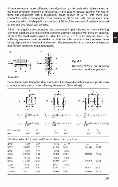
4
129
Cross section Jy Zy Jy Zy Jy Zy
mm cm4 cm3 cm4 cm3 cm4 cm3
Calculated values for Jy in cm4 and Zy in cm3, if a´ = d and d3 = 5 cm
50/51 1.355 1.80 5.15 4.125 — —50/10 10.830 7.20 41.25 16.5 341.65 62.10
60/51 1.626 2.16 6.18 4.95 — —60/10 12.996 8.64 49.50 19.8 409.98 74.52
80/51 2.168 2.88 8.24 6.60 — —80/10 17.328 11.52 66.00 26.4 546.64 99.36
100/51 2.71 3.6 10.3 8.25 — —100/10 21.66 14.4 82.5 33 683.3 124.2
120/10 26 17.28 99.00 39.6 819.96 149.04
If there are two or more stiffeners, the calculation can be made with higher values forthe main conductor moment of resistance. In the case of busbar packets with two orthree sub-conductors with a rectangular cross section of 60 %, with more sub-conductors with a rectangular cross section of 50 % and with two or more sub-conductors with a U-shaped cross section of 50 % of the moment of resistance basedon the axis 0-0 (ideal) can be used.
If four rectangular sub-conductors are connected in pairs by two or more stiffeningelements but there are no stiffening elements between the pairs with the 5 cm spacing,14 % of the ideal values given in Table 4-5, i.e. Zy = 1.73 b d2, may be used. Thestiffening elements must be installed so that the sub-conductors are prevented frombeing displaced in a longitudinal direction. The plasticity factor q is exactly as large asthat for non-combined main conductors.
Fig. 4-7
Direction of force and bendingaxes with conductor packets
Table 4-5
Formulae for calculating the ideal moments of inertia and resistance of composite mainconductors with two or more stiffening elements (100 % values).
bJ y = —– (B 3 – a´3)
12
bZ y = —— (B 3 – a´3)
6 B
bJ y = —– (B 3 – d 3
1 + d 3)12
bZ y = —— (B 3 – d 3
1 + d 3)6 B
bJ y = — (B 3 – d3
1 + d 32 – d 3
3)12
bZ y = —— (B 3 – d 31 + d 3
2 – d 33)6 B

130
Table 4-6
Moments of inertia and resistance for flat bars
Configuration flat upright
Calculation example
Busbar configuration as shown in Fig. 4-2 with three main conductors of three sub-conductors each with rectangular cross section 80 mm × 10 mm of 3.2 m length from
E – Al Mg Si 0.5 F 17.
Rp0.2 = 12 000 N /cm2 (Table 13-1)
Rp0.2 = 18 000 N /cm2 (Table 13-1)
Stiffeners for each main conductor consist of the tee-off bars and one extra stiffeningelement in each of the conductors (phases) L1 and L3.
Z x Jx Zy Jymm cm3 cm4 cm3 cm4
12 × 2 0.048 0.0288 0.008 0.000815 × 2 0.075 0.0562 0.010 0.00115 × 3 0.112 0.084 0.022 0.00320 × 2 0.133 0.133 0.0133 0.0013320 × 3 0.200 0.200 0.030 0.004520 × 5 0.333 0.333 0.083 0.020825 × 3 0.312 0.390 0.037 0.00525 × 5 0.521 0.651 0.104 0.02630 × 3 0.450 0.675 0.045 0.00730 × 5 0.750 1.125 0.125 0.03140 × 3 0.800 1.600 0.060 0.00940 × 5 1.333 2.666 0.166 0.04240 × 10 2.666 5.333 0.666 0.33350 × 5 2.080 5.200 0.208 0.05250 × 10 4.160 10.400 0.833 0.41660 × 5 3.000 9.000 0.250 0.06360 × 10 6.000 18.000 1.000 0.50080 × 5 5.333 21.330 0.333 0.083380 × 10 10.660 42.600 1.333 0.666
100 × 5 8.333 41.660 0.4166 0.104100 × 10 16.660 83.300 1.666 0.833120 × 10 24.000 144.000 2.000 1.000160 × 10 42.600 341.300 2.666 1.333200 × 10 66.600 666.000 3.333 1.660
Busbar dimensions

4
131
ls = 40 cml = 80 cma = 12 cmam = 12.4 cm with k1s = 0.97 as shown in Fig. 4-3 where a1s = a, d = 5 cm, b = 8 cma s = 2.3 cm (Table 4-3)Zs = 1.333 cm3 (Table 4-6)Zy = 26.4 cm3 (Table 4-5)Z = 0.6 · Zy = 0.6 · 26.4 cm3 = 15.84 cm3
vσ · vr = vσs · vr = 1 α = 1.1 (Table 4-4 for continuous beam with N 3, end bay supports α = 0.4)β = 0.73 (Table 4-4)
Size h b d r e Wx J x W y J y
mm mm mm mm mm mm cm3 cm4 cm3 cm4
150 50 25 4 2 7.71 5.24 13.1 1.20 2.07160 60 30 4 2 8.96 7.83 23.5 1.76 3.71170 70 32.5 5 2 9.65 12.4 43.4 2.57 5.87180 80 37.5 6 2 11.26 19.38 77.5 4.08 10.70100 100 37.5 8 2 10.96 33.4 167 5.38 14.29120 120 45 10 3 13.29 59.3 356 9.63 30.53
140 140 52.5 11 3 15.27 90.3 632 14.54 54.15160 160 60 12 3 17.25 130 1042 20.87 89.22
180 180 67.5 13 3 19.23 180 1622 28.77 138.90200 200 75 14 3 21.21 241 2414 38.43 206.72
Usection
The prospective peak short-circuit current without auto-reclosing is ip3 = 90 kA.
l 80Fm = 0.173 · i 2
p3 · —— = 0.173 · 902 · ——— = 9041 Nam 12.4
Fm · l 9041 N · 80 cmσ m = Vσ · Vr · β · ———— = 1.0 · 0.73 ———–——————– = 4167 N/cm2
8 · Z 8 · 15.84 cm3
ip3 ls 90 40Fs = 0.2 (——)2
· — = 0.2 (—–)2· —– = 3130 N
t as 3 2.3
Fs · ls 3130 N · 40 cmσ s = Vσs · Vr · ———— = 1.0 · ————————— = 5870 N/cm2
16 · Zs 16 · 1.333 cm3
Table 4-7
Moments of inertia and resistance for U busbars
Busbar configuration
r

132
σ tot = σ m + σ s = 4 167 N/cm2 + 5 870 N/cm2 = 10 037 N/cm2
σ tot = 10 037 N/cm2 < 0.8 · R´p0.2
0.8 · R´p0.2 0.8 · 18 000VF · Vr = ——————— = ——————— = 1.44σ tot 10 037
Fd = VF · Vr · α · Fm = 1.44 · 1.1 · 9 041 = 14 321 N
Conductor stresses
σ tot = 10 037 N/cm2 < 1.5 · Rp0,2 = 18000 N/cm2
σ s = 5 870 N/cm2 < Rp0,2 = 12 000 N/cm2
The busbars can be manufactured in accordance with the planned design.
Force on support
If the height of the point of application of force in Fig. 4-2 h ≤ 50 mm, a post insulator ofform C as in Table 13-34 at a rated force F = 16 000 N may be used. If the point ofapplication of the force F is higher than shown in the table, the forces must beconverted to take the maximum bending moment at the foot of the insulator intoaccount.
Assessment with respect to the conductor oscillations
Main conductor:γ = 3.56 (Table 4-4)l = 80 cmE = 70 000 N/mm2 (Table 13-1)J = b d 3 /12 = 0.67 cm4 (for single conductors, Table 1-22)m’ = 2.16 kg/m (per sub-conductor, cf. Table 13-7)fc = 82.4 Hz (where 1 N = 1 kg m/s2), valid without stiffening elementsfc = 144 Hz with stiffening elements (see DIN EN 60865-1)Vr = 1 (as in Fig. 4-6 where f = 50 Hz and fc /f = 2.88)Vσ = 1, VF = 1.5 (as in Fig. 4-4 and 4-5) (Regarding the elasticity of the supports, smaller values for fc must be used, i.e.for VF with values up to 2.7.)
Sub-conductors:γ = 3.56, l = 40 cm, fcs = 330 Hz, Vr = 1, Vσs = 1
In this case the short, rigid busbars, taking conductor vibrations into account, do notyield smaller values for products Vσ Vr, Vσ s Vr, VF Vr, i.e. lower stresses than when theplastic deformation is taken into account. This makes the above results determining.

150
For extremely short break times with short circuits (Tk < 15 ms), current limiting comesinto play and the thermal short-circuit current capability of carriers can only beassessed by comparison of the Joule integrals ∫ i 2 d t = f (Î "k ). The cut-off power of theovercurrent protection device must be less than the still permissible heat energy of theconductor.
Permissible Joule integrals for plastic-insulated conducters:
A = 1.5 2.5 4 10 25 50 mm2
∫ i 2 d t = 2.9 · 104 7.8 · 104 2.2 · 105 1.3 · 106 7.6 · 106 3.3 · 107 A2s
Current limiting overcurrent protection devices such as fuses or current limitingbreakers are particularly advantageous for short-circuit protection of carriers. Their cut-off power in the event of a short circuit is small. As a result the Joule heat impulse ∫ i 2 d t increases with increasing prospective short-circuit current I"k with the zero-currentinterrupter many times faster than with the current limiter.
Table 4-8
Permissible short-circuit conductor temperatures and rated short-time current densitiesfor plastic-insulated cables
Insulation Nominal Conductor Permissible Conductor Rated short-material voltage temperature end material time current
U0/U at beginning of temperature density (1 s) kV the short circuit A /mm2
PVC 0.6/1…6/10 70 °C 160 °C1) Cu 115Al 76
140 °C2) Cu 103Al 68
XLPE all ranges 90 °C 250 °C3) Cu 143LV and HV Al 94
1) for cross sections ≤ 300 mm2
2) for cross sections > 300 mm2
3) not permitted for soldered connections
4.3 Dimensioning of wire and tubular conductors for static loadsand electrical surface-field strength
4.3.1 Calculation of the sag of wire conductors in outdoor installations
Busbars and tee-offs must be rated for normal service current and for short circuit inaccordance with DIN EN 60865-1, see Sec. 4.2.
Al/St wire conductors are primarily used for the tensioned busbars, for connectingequipment and tee-off conductors Al wire conductors with a similar cross section areused.
For wire data, see Sections 13.1.4, Tables 13-22 to 13-33.
Wire conductor sag is determined by the dead-end strings, the weight of the wire, theanticipated ice load, the supplementary load of tee-offs or fixed contacts for single-column disconnectors, by the wire-pulling force, by built-in springs or the springstiffness of the supports and the cable temperature.
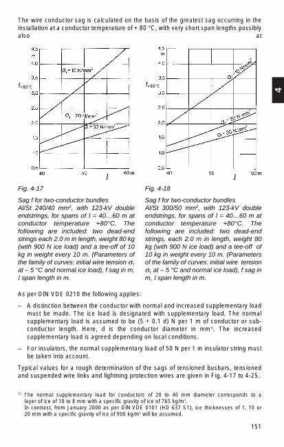
4
151
The wire conductor sag is calculated on the basis of the greatest sag occurring in theinstallation at a conductor temperature of + 80 °C, with very short span lengths possiblyalso at
Fig. 4-17
Sag f for two-conductor bundlesAl/St 240/40 mm2, with 123-kV doubleendstrings, for spans of l = 40…60 m atconductor temperature +80°C. Thefollowing are included: two dead-endstrings each 2.0 m in length, weight 80 kg(with 900 N ice load) and a tee-off of 10kg in weight every 10 m. (Parameters ofthe family of curves: initial wire tension σ1
at – 5 °C and normal ice load), f sag in m,l span length in m.
Fig. 4-18
Sag f for two-conductor bundles Al/St 300/50 mm2, with 123-kV doubleendstrings, for spans of l = 40…60 m atconductor temperature +80°C. Thefollowing are included: two dead-endstrings, each 2.0 m in length, weight 80kg (with 900 N ice load) and a tee-off of 10 kg in weight every 10 m. (Parametersof the family of curves: initial wire tensionσ1 at – 5 °C and normal ice load), f sag inm, l span length in m.
As per DIN VDE 0210 the following applies:
– A distinction between the conductor with normal and increased supplementary loadmust be made. The ice load is designated with supplementary load. The normalsupplementary load is assumed to be (5 + 0.1 d) N per 1 m of conductor or sub-conductor length. Here, d is the conductor diameter in mm1). The increasedsupplementary load is agreed depending on local conditions.
– For insulators, the normal supplementary load of 50 N per 1 m insulator string mustbe taken into account.
Typical values for a rough determination of the sags of tensioned busbars, tensionedand suspended wire links and lightning protection wires are given in Fig. 4-17 to 4-25.
l
1) The normal supplementary load for conductors of 20 to 40 mm diameter corresponds to a layer of ice of 10 to 8 mm with a specific gravity of ice of 765 kg/m3.In contrast, from January 2000 as per DIN VDE 0101 (HD 637 S1), ice thicknesses of 1, 10 or 20 mm with a specific gravity of ice of 900 kg/m3 will be assumed.
f+80°Cf+80°C
l

152
Sag of the tensioned busbars with loads, dead-end strings and tee-offs at every 10 m(width of bay) with a weight of 10 kg each
The sags and tensions of the busbar wires are influenced by their dead-end strings andtee-offs (point loads).
The busbar sags in a 123-kV outdoor installation with a bay width of 10.0 m can beroughly determined using the diagrams in Figs. 4-17 to 4-20. These give the mostcommon types of wire conductors like two-conductor bundle 240/40 mm2, two-conductor bundle 300/50 mm2, single-conductor wire 380/50 mm2 and single-conductorwire 435/55 mm2, for spans of 40…60 m and initial wire tensions σ1 = 10.0…30.0N/mm2 with ice load as per DIN VDE 0210, values for the sags occuring at + 80 °Cconductor temperature. This ice load is (5 + 0.1 d) N/m with wire diameter d in mm.
At 245- and 420-kV outdoor installations in diagonal arrangement with single-columndisconnectors the busbars take the weight of the disconnector fixed contacts instead ofthe tee-off wires. To limit the temperature-dependent change in sag, spring elementsare frequently included in the span to maintain the suspended contacts within the reachof the disconnector scissors.
Fig. 4-20
Sag f for single-conductor wires Al/St 435/55 mm2, with 123-kV double-end strings, for spans of l = 40…60 m atconductor temperature + 80°C. Thefollowing are included: two dead-endstrings, each 2.0 m in length, weight 80kg (with 900 N ice load) and a tee-offevery 10 m of 10 kg in weight.(Parameters of the family of curves initialwire tension σ1 at – 5 °C and normal iceload), f sag in m, l span length in m.
Fig. 4-19
Sag f for single-conductor wires Al/St 380/50 mm2, with 123-kV double-end strings, for spans of l = 40…60 m atconductor temperature + 80°C. Thefollowing are included: two dead-endstrings, each 2.0 m in length, weight 80kg (with 900 N ice load) and a tee-offevery 10 m of 10 kg in weight.(Parameters of the family of curves initialwire tension σ1 at – 5 °C and normal iceload), f sag in m, l span length in m.
l l
f+80°Cf+80°C

4
153
Fracture of an insulator of a double dead-end string
For safety reasons the wire connections in switchgear installations have double dead-end strings. The fracture of an insulator results in an increase in the sag in the middleof the span.
The greatest sag fk is roughly calculated as follows
3f k = f 2ϑ + – · 0,5 y · l
8
fϑ = sag at ϑ °C l = span length y = length of yoke of double-end string
Fig. 4-21
Sag f80 °C for spanned wire connections forspans up to 150 m with conductortemperature + 80 °C:
1 two-conductor bundle Al /St 560 /50 mm2,245-kV-double-end strings, σ1 20,0 N /mm2
at – 5 °C and normal ice load
2 two-conductor bundles Al /St 380 /50 mm2, 245-kV-double-end strings, σ1 30.0 N /mm2
at – 5 °C and normal ice load
3 two-conductor bundles Al /St 240 /40 mm2, 245-kV-double-end strings, σ1 40.0 N /mm2
at – 5 °C and normal ice load
4 two-conductor bundles Al /St 240 /40 mm2, 123-kV-double-end strings, σ1 10.0 N /mm2
at – 5 °C and normal ice load
5 two-conductor bundles Al /St 435 /50 mm2, 123-kV-double-end strings, σ1 20.0 N /mm2
at – 5 °C and normal ice load
(sag in logarithmic scale)
Sag of the spanned wire conductors
In many outdoor installations spanned wire conductors with dead-end strings arerequired. They generally only have a wire tee-off at the ends of the stays (near thestring insulators).
The sag can be calculated as follows when σx is known:
g nf x = —–———— [m' · (0.25 l2 – l k
2) + m k · lk]2 · σ x · A
fx sag m, σx horizontal component of the cable tension N/mm2, m’ mass per unit lengthof wire kg/m, with ice load if applicable, mK weight of insulator string in kg, A conductorcross section in mm2, l span including insulator strings in m, lk length of the insulatorstring in m, gn gravity constant. The sags of some wire conductor spanned with double-end strings in 123 and 245-kV switchgear installations can be taken from the curves inFig. 4-21 as a function of the span.
l
80°Cf

154
The curves in Fig. 4-22 can be used to make an approximate determination for y = 0.4 m of the greatest occurring sags.
Fig. 4-22
General determination of changes in sagin the event of a fracture of an insulator ofthe double-end spring. Length of yokebetween two insulators y = 0.4 m, fk maximum sag in m, fϑ sag at ϑ °C in m,parameter l length of span.
Sag of the earth wire
Outdoor installations are protected against lightning strikes by earth wires. Al/St wiresare generally used. Section 5.4 shows the configuration and the protection range of theearth wires in detail. They are placed along the busbar and at right-angles to theoverhead line and transformer feeder bays.
The ice load on the wires must also be considered here. For Al/St 44/32 and Al/St 50/30earth wires in Fig. 4-25, the sags can be determined at conductor temperature + 40 °C(because there is no current heat loss) and for span lengths to 60 m at cable tensionsσ1 = 10.0 to 30.0 N/mm2. In practice, the earth wires are generally spanned so their sagis identical to that of the busbars.
fϑ
fk
Wire connections of equipment
In outdoor installations the high-voltage equipment is generally connected with wirecondcutors. The applicable wire pull depends on the approved pull (static + dynamic) ofthe apparatus terminals. The minimum clearances and conductor heights overwalkways in switchgear installations are specified in Section 4.6. These are minimumdimensions. For rating for mechanical short-circuit current capability, see Section 4.2.

4
155
Tensions in wire connections
For the conductor sag of 0.5 m accepted in practice at + 80 °C conductor temperature,the required tensions depending on the span for the Al wire conductor cross sections240, 300, 400, 500, 625 and 800 mm2 can be taken from the curves in Figs. 4-23 and4-24. The permissible mechanical terminal load of the installed devices and apparatusmust be observed.
Fig. 4-23
Tensions σ1 for suspended wireconnections at –5 °C and normal ice load: 1 cable Al 240 mm2; 2 cable Al 400 mm2, 3 cable Al 625 mm2
Fig. 4-24
Tensions σ1 for suspended wireconnections at –5 °C and normal ice load: 4 cable Al 300 mm2; 5 cable Al 500 mm2, 6 cable Al 800 mm2
The sags and conductor tensions can be calculated with standard formulae used indesigning overhead lines. The sag in midspan is calculated with the parabolic equation:
(m' gn + Fz) l 2
f x = ———————8 · σx · A
f x sag in m σx horizontal component of the cond. tension N/mm2
A cond. cross section mm2 m’ conductor weight per unit length in kg/ml span in m Fz normal ice load in N/m (in DIN VDE 0210 designated
as supplementary load). Fz = (5 + 0.1 d) N/m.
Values for DlN wire conductors, see Section 13.1.4, Tables 13.22 to 13.29.
l l

156
Fig. 4-26
Sag of a connection of equipment atdistance c from terminal point A.1 rotary disconnector, 2 currenttransformer, A terminal point, l lengthof device connection, f max sag inmidspan, fc sag at distance c, H heightabove ground (see Fig. 4-37).
Fig. 4-25
Sag f for earth wire Al/St 44/32 mm2
and Al/St 50/30 mm2 — — — forspans of 20 to 60 m at conductor temperature + 40 °C (noJoule heat). (Parameters of the family ofcurves: initial tension σ1 at –5 °C andnormal ice load), f sag in m,l span length in m.
Sag in proximity to terminal points
When connecting the rotary disconnector, ensure that the cable sag does not affect thefunctioning of the disconnector arm. As shown in Fig. 4-26, the sag determines theminimum height of the conductor at the distance c from the terminal point A. The sag atdistance c is calculated as follows:
4 · f max · c · (l – c)f c = ——————————
l2
4.3.2 Calculation of deflection and stress of tubular busbars
In general, the deflection f and the stress σ of a tube is the result of its own weight
1 Q · l3 k · Q · lf = – · ——— and σ = —————
i E · J W
Where:
Q = m’ · g n · l load by weight of the tube between the support pointsl span (between the support points)E module of elasticity (for copper = 11 · 106, for Al = 6.5…7.0 · 106,
for steel = 21 · 106, for E-AlMgSi 0.5 F 22 = 7 · 106 N /cm2; see Table 13-1)
l

4
157
J moment of inertia (for tube J = 0.049 [D 4 – d 4]) as in Table 1-22W moment of resistance for bending (for tube W = 0.098 [D 4 – d 4]/D) as
in Table 1-22m’ weight of tube per unit of length (without supplementary load) in kg/m
(see Tables 13-5, 13-9 and 13-10)g n gravity constant 9.81 m/s2
i, k factors (see Table 4-9)
Table 4-9
Factors for calculating the deflection of tubular busbars
Type of support i k
Tube supported at both ends 177 0.125Tube one end fixed, one freely supported 185 0.125Tube fixed at both ends 384 0.0834Tube on three support points 185 0.125Tube on four support points 145 0.1Tube on more than four support points 130 0.11
As per DIN VDE 0101, an ice load equivalent to a layer of ice of 1.5 cm with a specificgravity of 7 kN/m3 must be taken into account (see footnote 1) on page 151). Whendoing the calculation with ice, the load Q (due to the weight of the tube) must beincreased by adding the ice load.
A permissible value for the compliance is only available as a typical value for opticalreasons. For the compliance under own weight, this is l /150 or D and for thecompliance under own weight and ice l / 80.
Permissible value for the stress under own weight plus ice is Rp0.2 / 1.7 with Rp0.2 as inTable 13-1. Permissible value with simultaneous wind load is Rp0.2 / 1.5.
Example:
Given an aluminium tube E-AlMgSi 0.5 F 22 as in Table 13-10, with external diameter80 mm, wall thickness 5 mm, span 8 m, supported at both ends. Then
kg mQ = m’ · gn · l = 3.18 –— · 9.81 — · 8 m = 250 N
m s 2
J = 0.049 (84 – 74) cm4 = 83 cm4
(84 – 74)W = 0.098 ——–——cm3 = 20.8 cm3
8
The deflection is:
1 250 N · 83 · 106 cm3
f = — · ——————–————––—— = 2,9 cm77 7 · 106 (N/cm2) · 83 cm4
The stress is:
0.125 · 250 N · 800 cm Nσ = ——————–——————— = 12 ———
20.8 cm3 mm2
Deflection and stress are acceptable.

158
4.3.3 Calculation of electrical surface field strength
The corona effect on the conductor surface of overhead lines is a partial electricaldischarge in the air when the electrical field strength exceeds a critical value on theconductor surface.
There is no specification for the permissible surface field strength for outdoorinstallations. In general for overhead lines, the value is 16…19 kV/cm, in individualcases up to 21 kV/cm is approved. These values should also be retained withswitchgear installations. The surface field strength E can be calculated with thefollowing formula:
The following apply in the equations:
E electrical surface field strength
U nominal voltage
β multiple conductor factor (for tube = 1)
r L conductor radius
r T radius of the bundle
re equivalent radius of bundleconductor
a T centre-to-centre distance of sub-conductors
a centre-to-centre distance of mainconductors
h conductor height above ground
n number of sub-conductors perbundle
Example:
Lower busbars in a 420-kV outdoor installation with Al/St 4 × 560/50 mm2, as in Fig. 3-17a, Section 3.4.4, at a medium height of 9.5 m above ground: U = 380 kV, rL = 1.61 cm, aT = 10 cm, a = 500 cm, h = 950 cm, n = 4. With these figures, the aboveequations yield:
The calculated value is within the permissible limits. This configuration can be designedwith these figures.
U βE = —– · —————————–——
3 a 2 · hrL · In (— · ————–—)re
1 + (n – 1) rL / rTwhere β = ——————––––
n
1.611 + (4 – 1) ——
7.07β = ——————–— = 0.42
4
re = nn · r L · r T
n–1
aTr T = ——————
2 · sin (π / n)
10 cmr T = ———— = 7.07 cm
π2 · sin –
4
re = 44 ·1.61· 7.073 = 6.91 cm
380 kV 0,42 kVE = ——— · —————————––——————————— = 13.5 —–
3 500 2 · 950 cm1.61 cm In (—— · ———————–———)6.91 4 · 9502+ 5002
4 h2 + a2

4
159
4.4 Dimensioning for continuous current rating4.4.1 Temperature rise in enclosed switch boards
Electrical equipment in switchboards gives off loss heat to the ambient air. To ensurefault-free function of this equipment, the specified limit temperatures must be retainedinside the switchboard.
The following applies according to the relevant IEC or VDE specifications
– with open installations as ambient temperature the temperature of the ambient roomair (room temperature ϑ).
– in closed installations as ambient temperature the temperature inside the enclosure(inside air temperature ϑi).
– as temperature rise the difference between inside air temperature (ϑi) and room airtemperature (ϑ).
The most significant heat sources inside the enclosure are the conducting paths in themain circuit. This includes the circuit-breakers and fuses, including their connectionsand terminals and all the auxiliary equipment in the switchboard.
Inductive heat sources such as eddy currents in steel parts only result in localtemperature rises. Their contribution is generally negligible for currents < 2500 A.
The power dissipation for the electrical equipment can be found in the relevant datasheets.
In fully enclosed switchboards (protection classes above IP 50) the heat is dissipated tothe outside air primarily by radiation and external convection. Thermal conduction isnegligibly small.
Experiments have shown that in the inside temperature is distributed depending on theheight of the panel and on the equipment configuration. The density variations of theheated air raises the temperature in the upper section of the enclosure.
The temperature distribution can be optimized when the electrical equipment with thegreatest power dissipation is positioned in the lower part of the panel, so the entireenclosure is involved in heat dissipation as far as possible.
When installed on a wall, the panel should have 8…10 cm clearance from the wall. Thisallows the rear wall of the panel to be involved effectively in dissipating heat.
The average air temperature inside the enclosure, neglecting the heat radiation, can becalculated as follows:
PV eff∆ ϑ = ————α · AM
∆ ϑ Temperature increase of air inside enclosure
PV eff power dissipation with consideration of load factor as per DIN EN 60439-1 (VDE 0660 Part 500) Tab. 1
AM heat-dissipating surface of enclosure
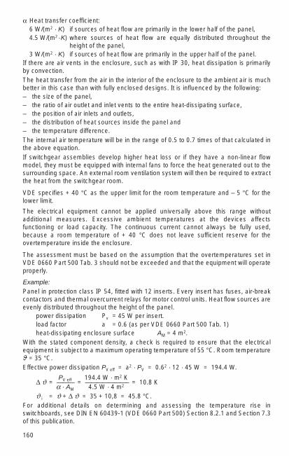
160
α Heat transfer coefficient:6 W/(m2 · K) if sources of heat flow are primarily in the lower half of the panel,4.5 W/(m2 ·K) where sources of heat flow are equally distributed throughout the
height of the panel,3 W/(m2 · K) if sources of heat flow are primarily in the upper half of the panel.
If there are air vents in the enclosure, such as with IP 30, heat dissipation is primarilyby convection.The heat transfer from the air in the interior of the enclosure to the ambient air is muchbetter in this case than with fully enclosed designs. It is influenced by the following:– the size of the panel,– the ratio of air outlet and inlet vents to the entire heat-dissipating surface,– the position of air inlets and outlets,– the distribution of heat sources inside the panel and– the temperature difference.The internal air temperature will be in the range of 0.5 to 0.7 times of that calculated inthe above equation.If switchgear assemblies develop higher heat loss or if they have a non-linear flowmodel, they must be equipped with internal fans to force the heat generated out to thesurrounding space. An external room ventilation system will then be required to extractthe heat from the switchgear room.
VDE specifies + 40 °C as the upper limit for the room temperature and – 5 °C for thelower limit.
The electrical equipment cannot be applied universally above this range withoutadditional measures. Excessive ambient temperatures at the devices affectsfunctioning or load capacity. The continuous current cannot always be fully used,because a room temperature of + 40 °C does not leave sufficient reserve for theovertemperature inside the enclosure.
The assessment must be based on the assumption that the overtemperatures set in VDE 0660 Part 500 Tab. 3 should not be exceeded and that the equipment will operateproperly.
Example:Panel in protection class IP 54, fitted with 12 inserts. Every insert has fuses, air-breakcontactors and thermal overcurrent relays for motor control units. Heat flow sources areevenly distributed throughout the height of the panel.
power dissipation Pv = 45 W per insert.load factor a = 0.6 (as per VDE 0660 Part 500 Tab. 1)heat-dissipating enclosure surface AM = 4 m2.
With the stated component density, a check is required to ensure that the electricalequipment is subject to a maximum operating temperature of 55 °C. Room temperatureϑ = 35 °C.Effective power dissipation PV eff = a2 · PV = 0.62 · 12 · 45 W = 194.4 W.
PV eff 194.4 W · m2 K ∆ ϑ = ——— = ———————– = 10.8 K
α · AM 4.5 W · 4 m2
ϑ i = ϑ + ∆ ϑ = 35 + 10,8 = 45.8 °C.For additional details on determining and assessing the temperature rise inswitchboards, see DIN EN 60439-1 (VDE 0660 Part 500) Section 8.2.1 and Section 7.3of this publication.

4
161
4.4.2 Ventilation of switchgear and transformer rooms
Design criteria for room ventilation
The air in the room must meet various requirements. The most important is not toexceed the permissible maximum temperature. Limit values for humidity and air quality,e.g. dust content, may also be set.
Switchboards and gas-insulated switchgear have a short-term maximum temperatureof 40 °C and a maximum value of 35°C for the 24h average. The installationrequirements of the manufacturers must be observed for auxiliary transformers, powertransformers and secondary installations.
The spatial options for ventilation must also be considered. Ventilation cross sectionsmay be restricted by auxiliary compartments and buildings. If necessary, the loss heatcan be vented through a chimney. If HVAC (air-conditioning) installations and air ductsare installed, the required space and the configuration must be included at an earlystage of planning.
Ultimately, economic aspects such as procurement and operating expenses must betaken into account as well as the reliability (emergency power supply and redundancy)of the ventilation.
At outside air temperatures of up to 30 °C, natural ventilation is generally sufficient. Athigher temperatures there is danger that the permissible temperature for the equipmentmay be exceeded.
Figs. 4-27 and 4-28 show frequently used examples of room ventilation.
Fig. 4-27
Compartment ventilation: a) Simple compartment ventilation, b) compartmentventilation with exhaust hood above the switchboard, c) ventilation with false floor, d) ventilation with recirculating cooling system

162
The ventilation efficiency is influenced by the configuration and size of the incomingair and exhaust air vents, the rise height of the air (centre of incoming air opening tocentre of exhaust air opening), the resistance in the path of the air and the temperaturedifference between incoming air and outgoing air. The incoming air vent and theexhaust air vent should be positioned diagonally opposite to each other to preventventilation short circuits.
If the calculated ventilation cross section or the chimney opening cannot bedimensioned to ensure sufficient air exchange, a fan will have to be installed. It must bedesigned for the required quantity of air and the pressure head.
If the permissible room temperature is only slightly above or even below the maximumoutside temperature, refrigeration equipment or air-conditioning is used to control thetemperature.
In ventilated and air-conditioned compartments occupied by personnel for extendedperiods the quality regulations for room air specified by DIN 1946 must be observed.
The resistance of the air path is generally:R = R1 + m2 R2.
Here: R1 resistance and acceleration figures in the incoming air duct, R2 resistance andacceleration figures in the exhaust air duct, m ratio of the cross section A1 of theincoming air duct to the cross section A2 of the exhaust air duct. Fig. 4-28 showscommon configurations.The total resistance consists of the components together. The following values for theindividual resistance and acceleration figures can be used for an initial approximation:acceleration 1 slow change of direction 0…0.6right-angle bend 1.5 wire screen 0.5…1rounded bend 1 slats 2.5…3.5a bend of 135 ° 0.6 cross section widening 0.25…0.91)
1) The smaller value applies for a ratio of fresh air cross section to compartment cross section of 1:2,the greater value for 1:10.
Fig. 4-28
Cross section through transformer cells:
a) incoming air is channelled over ground, exhaust air is extracted through a chimney.b) as in a), but without chimney. c) incoming air is channelled below ground, exhaustair is removed through an opening in the wall of the transformer compartment.d) transformer compartment with fan. A1 = incoming air cross section, A2 = exhaust aircross section, H = “chimney” height, 1 = fan, 2 = exhaust air slats, 3 = inlet air gratingor slats, 4 = skirting, 5 = ceiling.

Calculation of the quantity of cooling air:· QL
V0 = ———— ; ∆ϑ = T2 – T1cpL · ∆ϑ
With temperature and height correction1) the following applies for the incoming air flow:· · T1 g · H
V1 = V0 · — · e–
——T0 RL · T0
V0 = standard air volume flow at sea level, p0 = 1013 mbar, T0 = 273 K = 0 °C,T1 = cooling air temperature (in K),T2 = exhaust air temperature (in K),
mg = gravitational acceleration, g = 9.81 — ,
s2
H0 = height above sea level,kJ
RL = gas constant of the air, RL = 0.287 ——— ,kg · K
kJcpL = specific heat capacity of the air, cpL = 1.298 ———— ,
m3 · KQL = total quantity of heat exhausted by ventilation: QL = PV + ΣQ,PV = device power loss, ΣQ = heat exchange with the environment.
1) May be neglected at up to medium installation height and in moderate climates
At high power dissipation and high temperatures, solar radiation and thermalconduction through the walls can be neglected. Then QL = PV.
Example:At given incoming air and exhaust air temperature, the power dissipation PV should beexhausted by natural ventilation. The volume of air required should be calculated:T2 = 40 °C = 313 K, T1 = 30°C = 303 K, PV = 30 kW = 30 kJ/s, height above sea level = 500 m
· PV T1 g · H m 3 m 3
V1 = —————— · — · e–
——— = 2,4 — = 8640 —cpL (T2 – T1) T0 RL · T0 s h
If the warm air is exhausted directly over the heat source, this will increase the effectivetemperature difference ∆ϑ to the difference between the temperature of the outsideair and the equipment exhaust air temperature. This will allow the required volume ofcooling air to be reduced.
Calculation of the resistances in the air duct and the ventilation cross section:
Based on the example in Fig. 4-28a, the following applies:
for incoming air: acceleration 1screen 0.75widening in cross section 0.55gradual change of direction 0.6
R1 = 2.9
for exhaust air: acceleration 1right-angle bend 1.5slats 3
R2 = 5.5
4
163
g · H ———RL · T0
g · H ———RL · T0

164
If the exhaust air duct is 10 % larger than the incoming air duct, thenA1 1
m = —– = —– = 0.91 and m2 = 0.83,A2 1.1
then R = 2.9 + 0.83 · 5.5 = 7.5.
The ventilation ratios can be calculated with the formulaPV
2
(∆ ϑ)3 · H = 13.2 —– (R1 + m2 R2).A2
1
numerical value equation with ∆ ϑ in K, H in m, PV in kW and A1 in m2.
Example:
transformer losses PV = 10 kW, ∆ ϑ = 12 K, R = 7.5 and H = 6 m yield:
A1 ≈ 1 m2.
Practical experience has shown that the ventilation cross sections can be reduced if thetransformer is not continuously operated at full load, the compartment is on the northside or there are other suitable intervals for cooling. A small part of the heat is alsodissipated through the walls of the compartment. The accurate calculation can be doneas per DIN 4701. For the design of transformer substations and fire-preventionmeasures, see Section 4.7.5 to 4.7.6.
Fans for switchgear and transformer rooms
Ventilation fans, in addition to their capacity, must compensate for the pressure lossesin the air path and provide blow-out or dynamic pressure for the cooling air flow. Thisstatic and dynamic pressure can be applied with ∆p ≈ 0.2…0.4 mbar.
Then the propulsion power of the fan is:
V · ∆pPL = ——–—, η = efficiency
η
Example:
For the cooling air requirement of the transformer in the example above, where Pv = 30 kW, with V
.= 2.4 m3/s, η = 0.2, ∆p = 0.35 mbar = 35 Ws/m3
the fan capacity is calculated as:
2.4 · 0.35PL = ————— = 0.42 kW.
0.2
Resistances in the ventilation ducts and supplementary system components, such asdust filters, must be considered separately in consultation with the supplier.
For sufficient air circulation, a minimum clearance between the equipment and the wallis required, depending on the heat output. For auxiliary transformers, this is about 0.4m, for power transformers about 1 m.
4.4.3 Forced ventilation and air-conditioning of switchgear installations
Overview and selection
When planning switchgear installations, thermal loads resulting from heat dissipationfrom the installation and environmental conditions (local climate) must be taken intoaccount. This is generally done by:
.
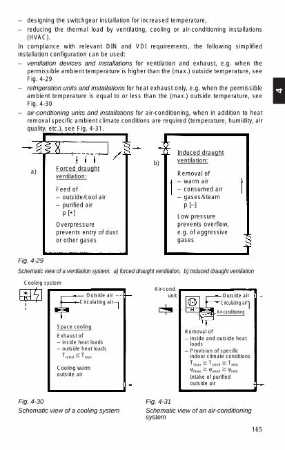
4
165
– designing the switchgear installation for increased temperature,– reducing the thermal load by ventilating, cooling or air-conditioning installations
(HVAC).In compliance with relevant DIN and VDI requirements, the following simplifiedinstallation configuration can be used:– ventilation devices and installations for ventilation and exhaust, e.g. when the
permissible ambient temperature is higher than the (max.) outside temperature, seeFig. 4-29
– refrigeration units and installations for heat exhaust only, e.g. when the permissibleambient temperature is equal to or less than the (max.) outside temperature, seeFig. 4-30
– air-condtioning units and installations for air-conditioning, when in addition to heatremoval specific ambient climate conditions are required (temperature, humidity, airquality, etc.), see Fig. 4-31.
a)b)
Forced draughtventilation:
Feed of– outside/cool air– purified air
p [+]
Overpressureprevents entry of dustor other gases
Induced draughtventilation:
Removal of– warm air– consumed air– gases/steam
p [–]
Low pressureprevents overflow, e.g. of aggressivegases
Fig. 4-29
Schematic view of a ventilation system: a) forced draught ventilation, b) Induced draught ventilation
Cooling systemAir-cond.
unitOutside airCirculating air
Outside airCirculating air
Air-conditioning
Space cooling
Exhaust of– inside heat loads– outside heat loads
Trated Tmax
Cooling warm outside air
Removal of– inside and outside heat
loads– Provision of specific
indoor climate conditionsTimax Trated Timinϕimax ϕrated ϕimin
Intake of purified outside air
Fig. 4-30 Fig. 4-31Schematic view of a cooling system Schematic view of an air-conditioning
system

166
Definitions and standards
– Permissible ambient temperatures are the max. permissible compartmenttemperatures as specified in DIN VDE or other standards.
– Telecommunications and electronics modules require special environmentalconditions and are specified in DIN 40040.
– In addition to the technical requirements, human (physiological) requirements maydetermine the compartment climate, e.g. the workplace regulations in Germany.
– The (max.) outside temperature is defined as the maximum outside temperaturesoccurring at the set-up area. It is selected from relevant climate tables, such asgiven in an encyclopedia or using information from meteorological organizations.
– Space heating systems in substation design is only relevant for occupiedcompartments. It is used almost exclusively in connection with ventilation or air-conditioning systems.
– Some of the most important and internationally accepted regulations (standards)are listed below:– DIN 4701 – Calculating heat requirements –– DIN 1946 – Ventilation engineering –– VDI 2078 – Calculating cooling loads –– Ashrae Handbook (NEW YORK)– Carrier Handbook of air-conditioning system design (NEW YORK).
Basis for HVAC design is calculation of the thermal loads (Qth) (heat balance).
Qth = Qtr + Qstr + Qi + Q a
Qtr = heat transmission by the areas around the room (outside heat loads)= A (m2) · k (W/m2 · K) · ∆ T (K)
Qstr = radiation heat from exterior areas exposed to the sunQ i = installation and personnel heat (inside heat loads)Qa = heat from outside air, humidifiers and dehumidifiers (outside heat loads)
= m (kg/h) · c (W h / kg · K) · ∆T (K) (without dehumidifiers)= m (kg/s) · ∆h (kJ/kg) (with dehumidifiers)
A = areas around the compartment (m2)k = heat transmission coefficient (W/m2) ∆T = temperature difference m = quantity of air flow/outside air flow (kg/h])c = specific heat capacity of air (Wh/kg.K) ∆h = difference of the specific outside air enthalpy (Wh/kg)
This is calculated in compliance with various DIN, VDI or relevant international rules.

4
167
4.4.4 Temperature rise in enclosed busbars
Busbars in medium and low-voltage substation design are often installed in smallcompartments or in conduits. For this reason they are subject to different thermalconditions to busbar configurations installed in the open general compartment.
It is not possible to select the busbar cross sections directly from the load tables inSection 13.1.2. Because of the number of parameters influencing the temperature ofenclosed busbars (such as position of the busbars in the conduit, conduit dimensions,ventilation conditions), the permissible current load must be calculated for the specificconfiguration.
The heat network method has proven useful for this calculation; Fig. 4-32 b.
Heat flows are generated by power dissipation.
Symbols used: Indices used:α Heat transfer coefficient D Forced coolingA Effective area K Convector P Heat output S RadiationR Equivalent thermal resistance O Environment ∆ ϑ Temperature difference 1 Busbar D Throughput of circulating 2 Inside air
cooling medium (D = V/t) 3 EnclosureC Radiant exchange numberT Absolute temperaturecp Specific heatρ Density
Thermal transfer and thermal resistances for radiation:
1PS = αS · AS · ∆ ϑ or RS = —–——αS · AS
= C13 · As · (T14 – T3
4) where αs =for the convection:
1PK = αK · AK · ∆ ϑ or RK = —–——αK · A K
for the circulating cooling medium:1PD = cp · ρ · D · ∆ ϑ or RD = —–———
cp · ρ · D
For additional information, see Section 1.2.5.
For information on temperature rise of high-current busbars, see Section 9.2.
Fig. 4-32
Temperature risein enclosedbusbarsa) thermal flow,b) heat network
environment
C13 (T14 – T3
4)∆ ϑ
P1 P3
P1
RK30RK12
RS13
RK23
RD20
RS30
RK12 RK23 RK30
RS13 RS30
P3
ϑ3 ϑ0ϑ1
RD20
b)a)

168
4.4.5 Temperature rise in insulated conductors
Conductors have a real resistance. This causes current thermal losses by current flow.The conductors and the insulation around them become warmer.
One part of the heat quantity developed in the line (power dissipation):d
Pc = c · γ · A — ∆ ϑ is stored and the other part isd t
PA = α · U · ∆ ϑ dissipated to the environment.
The heat process can be described as follows:
c · γ · A d A · ρ I———– · — ∆ ϑ + ∆ ϑ = —–— (—)2
α · U d t α · U A
Here:
∆ ϑ = conductor overtemperature (K)∆ ϑe = end value of the conductor overtemperature (K)α = heat transfer coefficient (9…40 W/(m2 K)c = specific heat (384.38 Ws/K · kg for copper)γ = density (8.92 · 10–3 kg /cm3 for copper)ρ = specific resistance (0.0178 Ωmm2/m at 20 °C for copper)A = conductor cross sectionU = conductor circumferenceI = current in conductor (A)
The stationary state in the temperature rise occurs when all the power dissipationgenerated can be dissipated to the environment. This is the case when the temperaturechange is zero:
ρ · A I∆ ϑe = —–— (—)2
.α · U A
The solution of the differential equation yields the overtemperature in relation to time: 1
– ––∆ ϑ = ∆ ϑe · (1 – e T ).
T is referred to as the time constant. It is the scale for the time in which the endtemperature ∆ ϑe would be reached if the temperature rise were constant, therefore ifthe generated heat is completely stored in the conductor and the thermal dissipation isequal to zero. It is:
c · γ · A thermal storage capacityT = ———— = ————————–——————
α · U thermal dissipation capacity
The result of this is that T increases with the cross section of the conductor and by αalso depends on the way it is laid and the accumulation of conductors. For example,multicore PVC copper conductors or cables laid well apart on the wall have thefollowing heating time constants:
A = 1.5 2.5 4 10 25 95 150 240 mm2
T = 0.7 1.0 1.5 3 6 16 23 32 min
Continuous operation occurs when the equilibrium temperature is reached. In practice,this is the case with 4 to 5 times the value of the time constants. A higher load may beapproved for intermittent operation, so long as t < 4 · T.

4
169
Excessively high conductor temperatures endanger the conductors and theenvironment. Care must be taken to ensure that non-permissible temperatures cannotoccur. The limit temperature of the conductors for continuous load is:
– with rubber insulation 60 °C and – with plastic insulation 70 °C – with plastic insulation with increased heat resistance 100 °C.
In the event of a short circuit, the DIN VDE regulations allow a higher limit temperaturefor a brief period, see also Section 4.2.5.
The maximum load duration tBmax in which a conductor with the current carryingcapacity I z at higher load I a = a · I z has been heated to the still permissible limittemperature is:
a2
t Bmax = T · In (———)a 2 – 1Example:
Is a conductor of 1.5 mm2 Cu for a three-phase a.c. motor (Istart = 6 · In Mot) sufficientlyprotected against overload with the motor protection switch when the rotor is blocked?
The current-carrying capacity of the conductor is In Mot · 0.8.
a = 0.8 · 6 = 4,8T = 0.7 min = 42 s
4.82t Bmax = 42 s · I n (———) = 1.86 s
4.82 –1
Because the overload protection device only responds after about 6 s at 6 times currentvalue, a 1.5 mm2 Cu is not sufficiently protected. After 6 s this wire already reaches152 °C. A larger conductor cross section must be selected.
A 2.5 mm2 Cu wire (utilization 0.53) only reaches the limit temperature after 6.2 s.
4.4.6 Longitudinal expansion of busbars
Operational temperature variations result in longitudinal expansion or contraction of thebusbars. This is calculated from
∆ l = lo α ∆ ϑ.
For a busbar of 10 m in length at 50 K temperature difference, the following typicalvalues are obtained:
with Cu: ∆ l = 10 · 0.000017 · 50 = 0.0085 m = 8.5 mm,with Al: ∆ l = 10 · 0.000023 · 50 = 0.0115 m = 11.5 mm.
These temperature-caused longitudinal changes may cause significant mechanicalstresses on the conductors, on their supports and on connections to apparatus if thereare no e x p a n s i o n s e c t i o n s installed in long line segments.
The forces generated are very easy to calculate if the longitudinal change caused bythe difference in temperature (ϑ – ϑ0) = ∆ϑ is assumed to be equal to the longitudinalchange that would be caused by a mechanical force F, which means:
F l o∆ l = l o α ∆ ϑ = ——E A

170
Where:
l0 length of the conductor at temperature at which it was laid ϑo
∆ ϑ temperature differenceF mechanical stressA conductor cross sectionα linear coefficient of thermal expansion, for Cu = 0.000017 · K–1,
for Al = 0.000023 · K–1
E module of elasticity, for Cu = 110 000 N/mm2, for Al = 65 000 N /mm2.
The above equation gives the mechanical stress as:F = α · E · A · ∆ ϑ
and for ∆ ϑ = 1 K and A = 1 mm2 the specific stress:F’ = α · E.
Therefore, for copper conductors:F’Cu = 0.000017 · 110 000 = ≈ 1.87 N/(K · mm2)
and for aluminium conductors:F’Al = 0.000023 · 65 000 = ≈ 1.5 N/(K · mm2).
4.5 Rating power systems for earthquake safety
4.5.1 General principles
Earthquakes in 95 of 100 cases originate from faults at the edges of the tectonic plates.The remainder are caused by volcanic action and landslides. The tectonic plates floaton the surface of the viscous mantle of the earth and are subject to strong convectioncurrents. The relative motion of the rigid plates in relation to one another generateslocal mechanical tension peaks at their edges, which from time to time are released bysudden deformations. These vibrations are spread by seismic waves, which propagatein accordance with the laws of wave propagation by reflection and refraction in complexwaveforms and occur primarily as energetic surface waves in the frequency range of0.1 Hz to 30 Hz with strong horizontal acceleration at the surface of the earth. The mostenergetic waves are therefore in the range of the natural frequencies of devices andcomponents in high-voltage substations, but they must not adversely affect theirfunctioning in the preset limits. The ground acceleration amplitudes are mostly in therange of 0.3 to 0.7 g. The strong earthquake phase only lasts a few seconds. In total,an earthquake rarely lasts more than 1 to 2 minutes.The edges of the plates subject to earthquakes are primarily found in line reaching fromsouth-eastern Europe through central Asia to Indonesia and around the Pacific Ocean.Even in central Europe earthquakes of moderate power occur occasionally. For thisreason, even here nuclear installations also require verification of earthquake safety forall important components. This is also required for high-voltage power systems.
The most important parameters of an earthquake with respect to the mechanical stresson equipment and installations is the limit value of the acceleration of the ground at theinstallation site.
Characteristic values are:
– 5 m/s2 ( 0.5 g, qualification class AF5),– 3 m/s2 ( 0.3 g, qualification class AF3) and– 2 m/s2 ( 0.2 g, qualification class AF2)

4
171
For the oscillation in the horizontal direction (x and y component). The vertical stress iscalculated with half that value for every case. Of primary importance for the mechanicalstress of equipment and device combinations is their mechanical natural frequencies,which are generally in the frequency spectrum of the seismic excitation. When verifyingearthquake safety, the excitation with the natural frequency values of the equipmentmust be regarded as the “worst case”.
The temporal process of the seismic excitation, i.e. the process of the oscillation of theground at the installation site, can be selected differently for the verification. Thefollowing options are available:– Continuous sine wave with natural frequencies– Several (5) groups of 5 sinusoidal increasing and decreasing load cycle oscillations
with natural frequency (5-sine beat, Fig. 4-33) separated by pauses– Exponentially damped decaying load cycle oscillations with natural frequency
(e-beat, Fig. 4-34)– Simulation of an earthquake sequence typical for the installation site (Fig. 4-35)
The earthquake safety of equipment and installations (DIN EN 61166 (VDE 0670 Part 111), IEC 60068-3-3) can be verified in different ways, i.e. – by testing,– by a combination of testing and calculation or– by calculation alone.
Fig. 4-33
Result of 5 sine wave impulses with 5 load cycles each
Fig. 4-34
ag ground acceleration
Exponential beat,“e-beat” for short,as excitation function for simulationof an earthquake shock
Am
plitu
de
1st sine waveimpulse
2nd sine waveimpulse
3rd sine waveimpulse
5 load cyclesf = test frequency
1/fTime
4th sine waveimpulse
5th sine waveimpulse
Pause Pause Pause Pause
ag
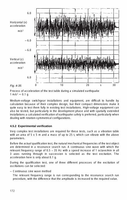
172
Medium-voltage switchgear installations and equipment, are difficult to handle bycalculation because of their complex design, but their compact dimensions make itquite easy to test them fully in existing test installations. High-voltage equipment canalso be tested, but particularly in the development phase and with spatially extendedinstallations a calculated verification of earthquake safety is preferred, particularly whendealing with rotation-symmetrical configurations.
4.5.2 Experimental verification
Very complex test installations are required for these tests, such as a vibration tablewith an area of 5 x 5 m and a mass of up to 25 t, which can vibrate with the aboveparameters.
Before the actual qualification test, the natural mechanical frequencies of the test objectare determined in a resonance search run. A continuous sine wave with which therelevant frequency range of 0.5 – 35 Hz with a speed increase of 1 octave/min in all 3 axes running through in succession is selected as the test excitation. Theacceleration here is only about 0.1 g.
During the qualification test, one of three different processes of the excitation ofoscillations can be selected:
– Continuous sine wave methodThe relevant frequency range is run corresponding to the resonance search runprocedure, with the difference that the amplitude is increased to the required value.
Horizontal (x)acceleration
m/s2
6.0
– 6.0
Vertical (z)acceleration
m/s2
– 6.0
6.0
Fig. 4-35
Process of acceleration of the test table during a simulated earthquake 1 m/s2 0.1 g
0 10 20 s 30
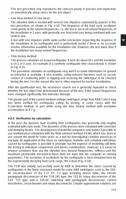
4
173
This test procedure only reproduces the stresses poorly in practice and representsan unrealistically sharp stress for the test object.
– Sine beat method (5-sine beat)The vibration table is excited with several sine impulses separated by pauses in thistest procedure, as shown in Fig. 4-33. The frequency of the load cycle oscillationcorresponds to the natural frequencies, i.e. the test is run in all natural frequencies ofthe installation in 2 axes, with generally one horizontal axis being combined with onevertical axis.A test with sine impulses yields quite useful conclusions respecting the response ofthe installation to an earthquake and is particularly useful if there is no accurateseismic information available for the installation site. However, the test takes time ifthe installation has many natural frequencies.
– Time history methodThis process simulates an actual earthquake. It lasts for about 30 s and the excitationis on 2 or 3 axes. An example of a synthetic earthquake time characteristic is shownin Fig. 4-35.This procedure simulates an earthquake very well if accurate information on groundacceleration is available. It also enables safety-relevant functions such as securecontact of conducting paths or tripping and reclosing the switchgear to be checkedduring the test. For this reason this test is often required for nuclear installations.
After the qualification test, the resonance search run is generally repeated to checkwhether the test object has deteriorated because of the test. If the natural frequencieshave changed significantly, this indicates damage.
The greater part of the current medium-voltage switchgear range from ABB Calor Emaghas been verified for earthquake safety by testing, in some cases with the 5-sine-beat method, in part while using the time history method with excitationaccelerations to 0.7 g.
4.5.3 Verification by calculation
In the past, the dynamic load resulting from earthquakes was generally only roughlyestimated with static loads. The dynamics of the process were simulated with correctionand damping factors. The development of powerful computers now makes it possible touse mathematical simulation with the finite-element method (FEM), which has been inuse around the world for some years as a tool for investigating complex processes ofany type. Its application to the stress on switchgear, modules and complete switchbayscaused by earthquakes is possible in principle, but the expense of modelling still limitsthe testing to individual components and device combinations. However, it is easier toanalyse variations than use the vibration test. Natural frequencies, stiffness and themaximum permissible mechanical basic data are input into the computer as startingparameters. The excitation of oscillations by the earthquake is best simulated here bythe exponentially decaying load cycle surge, the e-beat (Fig. 4-34).
The FEM was initially successfully used by ABB to determine the stress caused byearthquakes in the finely structured model for some ABB switchgear, such as the 550-kV circuit-breakers of the ELF SP 7-2 type including device table, the 245-kVpantograph disconnector of the TFB 245 type, the 123 kV rotary disconnector of theSGF 123 type and a 245-kV switchbay with pantograph disconnector, currenttransformer, circuit-breaker and rotary disconnector. Simpler approximate solutions are

174
currently being developed in two directions, in one case an FEM with a roughlystructured model and in the other case an alternative calculation procedure withstatically equivalent loads derived from the dynamic process with earthquakes.
4.6 Minimum clearances, protective barrier clearances and widths ofgangways
Key to symbols used
Um (kV) maximum voltage for apparatus
Un (kV) nominal voltage
U rB (kV) rated lightning impulse withstand voltage
U rS (kV) rated switching impulse withstand voltage
N (mm) minimum clearance (Table 4-10)
B1 (mm) protective barrier clearances for solid-panel walls (≥ 1800 mm high)with no openings. The dimension applies from the interior of the solidwall. B1 = N
B2 (mm) protective barrier clearances with wire mesh, screens or solid walls (≥1800 mm high)≤ 52 kv: B2 = N + 80 mm and protection class IP2X,> 52 kV: B2 = N + 100 mm and protection class IP1XB.
O1, O2 (mm) protective barrier clearances for obstacles, such as rails, chains,wires, screens, walls (< 1800 mm high)for indoor installations:O1 = N + 200 mm (minimum 500 mm),for outdoor installations:O2 = N + 300 mm (minimum 600 mm).rails, chains and wires must be placed at a height of 1200 mm to 1400 mm. With chains or wires, the protective barrier clearance mustbe increased by the sag.
C, E (mm) protective barrier clearances at the outer fence (≥ 1800 mm high) withsolid walls C = N + 1000 mm,with wire mesh, screens (mesh size ≤ 50 mm)E = N + 1500 mm
H (mm) minimum height of live parts (without protective barrier) aboveaccessible areas H = N + 2250 mm (minimum 2500 mm)
H’ (mm) minimum height of overhead lines at the outer fencing.≤ 52 kv: H’ = 4300 mm > 52 kV: H’ = N + 4500 mm (minimum 6000 mm)
T (mm) minimum transport clearance for vehicles T = N + 100 mm (minimum 500 mm)

4
175
4.6.1 Minimum clearances and protective barrier clearances in power systems with rated voltages over 1 kV (DIN VDE 0101)
Minimum clearances
The clearances of live parts of a system from one another and from earthed parts mustat least comply with Table 4-10. This table lists the minimum clearances for themaximum apparatus voltages assigned to the associated insulation levels as per DINEN 60071-1 (VDE 0111 Part 1). The various insulation levels available should beselected in accordance with the insulation coordination as per this standard.
Table 4-10
Minimum clearances of live parts of a system from one another and from earth as perDIN VDE 0101 (HD 637 S1).
In the areas of 1 kV < Um < 300 kV, the rated lightning impulse withstand voltage is thebasis for the rating.
1) These nominal voltages are not recommended for planning of new networks.2) This voltage value is not included in DIN EN 60071-1.
Nominal Maximum Short-duration Rated lightning Minimum voltage voltage for power frequency impulse withstand clearance (N)
apparatus withstand voltage phase-to-earthvoltage 1.2/50 µs and phase-to-
UrB phaseIndoor Outdoor
Un Um installationkV kV kV kV mm mm
3 3.6 10 20 60 12040 60 120
6 7.2 20 40 60 12060 90 120
10 12 28 60 90 15075 120 150
15 1) 17.5 38 75 120 16095 160 160
20 24 50 95 160125 220
30 36 70 145 270170 320
36 2) 41.5 80 170 320200 360
In the area of 1 kV < Um < 52 kV
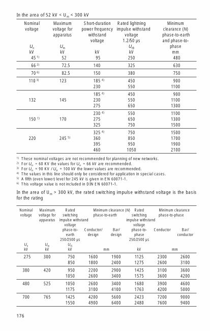
176
Nominal Maximum Short-duration Rated lightning Minimum voltage voltage for power frequency impulse withstand clearance (N)
apparatus withstand voltage phase-to-earthvoltage 1.2/50 µs and phase-to-
Un Um UrB phasekV kV kV kV mm45 1) 52 95 250 480
66 2) 72.5 140 325 630
70 6) 82.5 150 380 750
110 3) 123 185 4) 450 900230 550 1100
185 4) 450 900132 145 230 550 1100
275 650 1300
230 4) 550 1100150 1) 170 275 650 1300
325 750 1500
325 4) 750 1500220 245 5) 360 850 1700
395 950 1900460 1050 2100
In the area of 52 kV < Um < 300 kV
Nominal Maximum Rated Minimum clearance (N) Rated Minimum clearancevoltage voltage for switching phase-to-earth switching phase-to-phase
apparatus impulse withstand impulse withstandvoltage voltage
phase-to- Conductor/ Bar/ phase-to- Conductor Bar/earth design design phase conductor
250/2500 µs 250/2500 µsUn Um UrS
kV kV kV mm kV mm
275 300 750 1600 1900 1125 2300 2600850 1800 2400 1275 2600 3100
380 420 950 2200 2900 1425 3100 36001050 2600 3400 1575 3600 4200
480 525 1050 2600 3400 1680 3900 46001175 3100 4100 1763 4200 5000
700 765 1425 4200 5600 2423 7200 90001550 4900 6400 2480 7600 9400
In the area of Um > 300 kV, the rated switching impulse withstand voltage is the basisfor the rating
1) These nominal voltages are not recommended for planning of new networks.2) For Un = 60 KV the values for Un = 66 kV are recommended.3) For Un = 90 KV / Un = 100 kV the lower values are recommended.4) The values in this line should only be considered for application in special cases.5) A fifth (even lower) level for 245 kV is given in EN 60071-1.6) This voltage value is not included in DIN EN 60071-1.
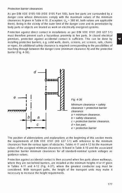
4
177
Fig. 4-36
Minimum clearance + safetyclearance = protective barrierclearance:a = minimum clearance, b = safety clearance, c = protective barrier clearance,d = live part, e = protective barrier
The position of abbreviations and explanations at the beginning of this section meetsthe requirements of DIN VDE 0101 (HD 637 S1) with reference to the minimumclearances from the various types of obstacles. Tables 4-11 and 4-12 list the maximumvalues of the assigned minimum clearances N listed in Table 4-10 and the associatedprotective barrier minimum clearances for all standard-nominal system voltages asguidance values.
Protection against accidental contact is then assured when live parts above walkways,where they are not behind barriers, are installed at the minimum heights H or H’ givenin Tables 4-11 and 4-12 (Fig. 4-37), where the greatest conductor sag must beconsidered. With transport paths, the height of the transport units may make itnecessary to increase the height requirements.
Protective barrier clearances
As per DIN VDE 0105-100 (VDE 0105 Part 100), bare live parts are surrounded by adanger zone whose dimensions comply with the maximum values of the minimumclearances N given in Table 4-10. (Exception: Um = 380 kV, both values are applicablethere). Being in the vicinity of the outer limit of the danger zone and its penetration bybody parts or objects are treated as work on electrically energized systems.
Protection against direct contact in installations as per DIN VDE 0101 (HD 637 S1)must therefore prevent such a hazardous proximity to live parts. In closed electricalpremises, protection against accidental contact is sufficient. This can be done byinstalling protective barriers, e.g. solid walls, doors, screens, arc screens, rails, chainsor ropes. An additional safety clearance is required corresponding to the possibilities ofreaching through between the danger zone (minimum clearance N) and the protectivebarrier (Fig. 4-36).
a
d
e
b
c

178
The upper edge of an insulator base must be at least 2250 mm over walkways if thereis no protective barrier installed.
If the protective barrier clearance is partly or completely bridged by insulators,protection against direct contact must be assured by panel walls, panel doors, screensor screen doors with a minimum height of 1800 mm (Fig. 4-38). Where the insulatorsare installed above 2250 mm, rails, chains or wires are sufficient (Fig. 4-38 b).
Fig. 4-37
Minimum heights of liveparts over walkways
Fig. 4-38
Minimum clearance bridged by insulators and design of walkways over live parts(dimensions in mm):
a) panel wall or panel door, b) screen or screen door, rail, chain or wire*) min. 1200 mm, max. 1400 mm
Walkways over live parts accessible during operation must be of solid plate. If rails,chains or wires are installed as protective barriers, they must be widened by the safetyclearance and a minimum 50 mm high edge must be installed as a limit (see Fig.4-38b). This is intended to prevent objects from falling on live parts.
4.6.2 Walkways and gangways in power installations with rated voltages over 1 kV (DIN VDE 0101)
The minimum width of walkways within outdoor installations should be a minimum of1000 mm, the minimum width of gangways in indoor installations should be 800 mm.For safety reasons these dimensions must not be reduced. Service aisles behindmetall-enclosed installations may be an exception; a minimum gangway width of 500mm is permissible here.
Panel wall or panel door Screen or screen door
Upper edge ofwalkway or depth of snow
Rail, chain orwire
2250
2250
B1
N
N
2250
B2O1,2
*)
H H
N

4
179
The minimum width of walkways and gangways must not be reduced, not even byprojecting parts such as fixed drives, control cabinets, switchgear truck in isolatedposition. When measuring the gangway width of indoor switchgear installations, theopen position of the cubicle door must be taken into account. Cubicle doors must slamshut in the escape direction. When the door is open, the gangway width must still be500 mm.
In the case of transport paths inside enclosed electrical premises, the dimensions for the transport unit must be agreed between the installer and the operator.The following regulations are applicable (Fig. 4-39):
Vehicles and similar may pass below live parts (without protection devices) or in theirvicinity when
– the vehicle, even with its doors open, and its load do not come into the danger zone(minimum transport clearance T = N + 100 mm; minimum 500 mm) and
– the minimum height H of live parts over walkways is maintained.
Fig. 4-39
Limit of the transport path inoutdoor switchgear installations
T
TT
H
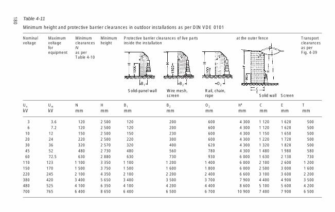
180
Un Um N H B1 B2 O2 H C E TkV kV mm mm mm mm mm mm mm mm mm
3 3.6 120 2 500 120 200 600 4 300 1 120 1 620 5006 7.2 120 2 500 120 200 600 4 300 1 120 1 620 500
10 12 150 2 500 150 230 600 4 300 1 150 1 650 50020 24 220 2 500 220 300 600 4 300 1 220 1 720 50030 36 320 2 570 320 400 620 4 300 1 320 1 820 50045 52 480 2 730 480 560 780 4 300 1 480 1 980 58060 72.5 630 2 880 630 730 930 6 000 1 630 2 130 730
110 123 1 100 3 350 1 100 1 200 1 400 6 000 2 100 2 600 1 200150 170 1 500 3 750 1 500 1 600 1 800 6 000 2 500 3 000 1 600220 245 2 100 4 350 2 100 2 200 2 400 6 600 3 100 3 600 2 200380 420 3 400 5 650 3 400 3 500 3 700 7 900 4 400 4 900 3 500480 525 4 100 6 350 4 100 4 200 4 400 8 600 5 100 5 600 4 200700 765 6 400 8 650 6 400 6 500 6 700 10 900 7 400 7 900 6 500
Table 4-11
Minimum height and protective barrier clearances in outdoor installations as per DIN VDE 0101
Nominal Maximum Minimum Minimum Protective barrier clearances of live parts at the outer fence Transportvoltage voltage clearances height inside the installation clearances
for N as perequipment as per Fig. 4-39
Table 4-10
Solid-panel wall Wire mesh, Rail, chain,screen rope
B1 B2 O2
CE
H
Solid wall Screen
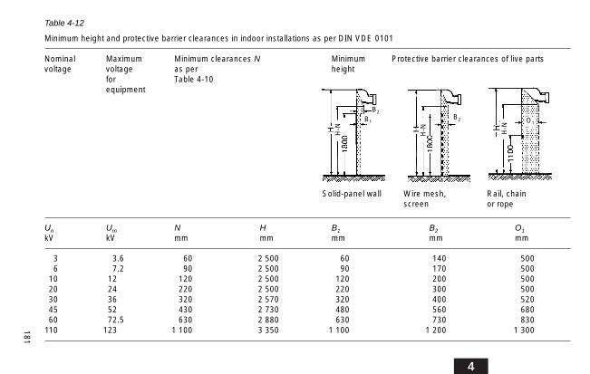
4
181
Un Um N H B1 B2 O1
kV kV mm mm mm mm mm
3 3.6 60 2 500 60 140 5006 7.2 90 2 500 90 170 500
10 12 120 2 500 120 200 50020 24 220 2 500 220 300 50030 36 320 2 570 320 400 52045 52 430 2 730 480 560 68060 72.5 630 2 880 630 730 830
110 123 1 100 3 350 1 100 1 200 1 300
Table 4-12
Minimum height and protective barrier clearances in indoor installations as per DIN VDE 0101
Nominal Maximum Minimum clearances N Minimum Protective barrier clearances of live partsvoltage voltage as per height
for Table 4-10equipment
Solid-panel wall Wire mesh, Rail, chainscreen or rope
H-N
H-N H-N
B2
B2
B1 O1

182
1) minimum passage height under obstacles, such as barriers2) minimum passage height under bare live parts
4.6.3 Gangway widths in power installations with rated voltages of up to 1 kV (DIN VDE 0100 Part 729)
Specifications for the arrangement of switchgear installations
They apply for both type-tested and partially type-tested switchgear installations andswitchboards
Control and service gangways
Switchgear installations and distribution boards must be configured and installed so thewidth and height of gangways are not less than the dimensions shown in Fig. 4-40. Theexits must also be accessible in emergencies even when the panel and housing doorsare open. These conditions are considered fulfilled if doors slam shut in the escapedirection or open completely. The remaining minimum accesses may not be less than500 mm.
Service and operational accesses with a length of more than 20 m must be accessiblefrom both ends. Access from both ends is also recommended for gangways that arelonger than 6 m. Exits must be placed so that the escape path inside a room of electricalor enclosed electrical premises is no more than 40 m long.
Fig. 4-40
Minimum dimensions for gangways
a) gangways for low-voltage installations with the minimum degree of protection IP 2X as per DIN 40 050.
b) gangways for low-voltage installations with degrees of protection below IP 2X.
See Section 5.7 for degrees of protection
The values of DIN VDE 0101 as the dimension for gangways are applicable for thegangway widths where low-voltage and high-voltage device combinations are installedfront-to-front in the same room (see Section 4.6.2).
Protective clearances DIN VDE 0660
Removable parts that are intended to prevent direct contact with live parts may only beremovable with a tool or key.

4
183
Fig. 4-40a shows the minimum dimensions for closed installations. The minimumdimensions in Fig. 4-40b are applicable for open installations in locked electricalpremisses only.
In the case of barriers, such as wooden railings, the gangway widths must meet theminimum dimensions for operating handles (900 or 700 mm) listed in Fig. 4-40b andalso the additional minimum clearance of 200 mm between barrier and live part givenin Fig. 4-41.
4.7 Civil construction requirements
The civil engineering consultant must determine a large quantity of information anddetails for the structural drawings required to design switchgear installations. Thestructural drawings are the basis for producing the structural design plans (foundation,shell and reinforcement plans, equipment plans). In Germany the ArbeitsgemeinschaftIndustriebau e. V. (AGI) has issued the following datasheets:
datasheet J11 for transformer compartmentsdatasheet J12 for indoor switchgeardatasheet J21 for outdoor transformersdatasheet J31 for battery compartments
The structural information includes the following data:
– spatial configuration of the installation components– aisle widths for control, transport and assembly– main dimensions of the station components– load specifications– doors, gates, windows with type of opening and type of fire-preventive or fire-
resistant design – ceiling and wall openings for cables, pipes or conduits– information on compartments with special equipment– information on building services– ventilation, air-conditioning information– floors including steel base frames– foundation and building earth switches– lightning protection– drainage.
The following design details must be observed:
Fig. 4-41
Minimum dimensions for barriers
184
4.7.1 Indoor installations
When planning indoor installations (substation buildings and switchboard rooms), inaddition to configuration to meet operational requirements, ensure that the selectedcompartments are not affected by groundwater and flooding and are also easilyaccessible for control and transport equipment and also for firefighting. The currentapplicable construction codes, regulations and directives must be observed.Construction laws include regulations that must be observed and in addition, thegenerally accepted engineering requirements apply.
Walls, ceilings and floors must be dry. Pipes carrying liquids, steam and flammablegases must not be laid in, above or under rooms intended for switchgear installations.If, however, necessary, structural measures for protection of the electrical installationsare required.
The clearance dimensions of an equipment room depend on the type, size andconfiguration of the switchbays, on their number and on the operating conditions. Therequired minimum aisle widths and safety clearances are specified in DIN VDE 0101 or DIN VDE 0105 Part 1.
The exits must be laid out so the escape route from the installation is no more than 40 m for rated voltages over 52 kV and no more than 20 m for rated voltages of up to52 kV. A servicel aisle more than 10 m long must have two exits, one of which may bean emergency exit.
The interiors of the switchgear house walls must be as smooth as possible to preventdust from accumulating. The brickwork must be plastered, but not ceilings in the areaof open installations, so switchgear parts are not subject to falling plaster.
The floor covering must be easy to clean, pressure-resistant, non-slippery andabrasion-proof (e.g. stoneware tiles, plastic covering, gravel set in concrete withabrasion-resistant protective coating to reduce dust formation); the pressure load onthe floor from transport of station components must be considered.
Steps or sloping floor areas must always be avoided in switchgear compartments.
Opening windows must be positioned so they can be operated. In open areas, this mustnot place personnel in danger of contacting live parts.
Windows in locked electrical premises must be secured to prevent access. Thiscondition is considered to be met by one of the following measures:
– The window consists of unbreakable materials.– The window is barred. – The bottom edge of the window is at least 1.8 m above the access level. – The building is surrounded by a fence at least 1.8 m high.
Ventilation and pressure relief
The compartments should be ventilated sufficiently to prevent the formation ofcondensation. To prevent corrosion and reduction of the creepage distance by highhumidity and condensation, it is recommended that the typical values for climate stresslisted in DIN VDE 0101 be observed in switchgear rooms. The following apply:
– the maximum relative humidity is 95 % in the 24 hour average,– the highest and lowest ambient temperature in the 24 hour average is 35 °C and
– 5 °C with “Minus 5 Indoor” class.

4
185
In areas of high pollution, the compartments must be kept at a low level of overpressurewith filtered air. The air vents required for this must prevent the entry of rain, spray waterand small animals. Sheetmetal covers must also be installed over the vents at heightsto about 2.50 m above ground. See Sections 4.4.2 and 4.4.3 for additional informationon ventilation.
SF6 installationsFor SF6 installations, it is recommended that the building be extended by the length ofone bay for installation and renovation purposes and that a hoist system with a liftingcapacity equal to the heaviest installation components be installed.Natural cross-ventilation in above-ground compartments is sufficient to remove theSF6 gas that escapes because of leakage losses. This requires about half of therequired ventilation cross section to be close to the floor.It must be possible to ventilate compartments, conduits and the like undercompartments with SF6 installations.Mechanical ventilation is not necessary so long as the gas content of the largestcontiguous gas space including the content of all connected SF6 tanks (based onatmospheric pressure) does not exceed 10% of the volume of the compartmentreceiving the leakage gas.Mechanical ventilation may be required in the event of faults with arcing.Reference is also made to the requirement to observe the code of practice“SF6 Installations” (Edition 10/92) of the professional association for precisionengineering and electrical engineering (BGFE, Germany).
Pressure reliefIn the event of an accidental internal arc in a switchgear installation, significantoverpressure occurs in switchgear compartments, in particular in those withconventional air insulation with high arc lengths. Damage to walls and ceilings causedby unacceptably high pressure load can be prevented by appropriate pressure reliefvents. Floor plates must be properly secured. Pressure relief facilities in switchgearrooms should meet the following criteria:– they should normally be closed to prevent the entry of small animals, snow, rain etc.;
light, self-actuating opening of the facility at an overpressure of less than 10 mbar;
– pressure relief in an area where there are usually no personnel; – no parts should become detached during pressure relief.
Cable layingThe options listed below are available for cable laying:Tubes or cable conduit forms, covered cable conduits, cable conduits accessible ascrawl space and cable floors, accessible cable levels.Tubes or cable conduit forms are used to lay single cables. To avoid water damagewhen laid outside they should be sloped. The bending radius of the cable used shouldbe observed for proper cable layout.Covered cable conduits are intended when several cables are laid together, with thewidth and depth of the conduit depending on the number of cables. The covers of theconduits should be fireproof, non-slip and non-rattling and should not have a raisededge. They must able to take the weight of transport vehicles carrying electricalequipment during installation. The conduits should be placed before the compartmentsto allow cable work to be done at any time without having to disconnect equipment.

186
Cable conduits accessible as crawl spaces and cable floors should be at least 1.50 mwide; the overhead clearance should not be less than 1.00 m to allow for any cablecrossings. Access and ventilation openings and the required cable accesses must betaken into account.
Accessible cable conduits and cable levels are required for a large accumulation ofcables in larger installations. A height of 2.10 m (to the lower edge of the support girder)is recommended to provide space for the required lighting and suspended cables. Thecables can be laid on cable racks and also fastened to supports using cable clamps.Escape paths (emergency exits) must be available. Access doors must open outwards,should be airtight when closed, must be fire-resistant and have a panic lock.
Auxiliary cables are laid on separate cable racks or on supports beneath the ceiling.
The VDEW directives “Empfehlungen für Maßnahmen zur Herabsetzung vontransienten Überspannungen” (recommendations for measures to reduce transientovervoltages) in secondary lines are particularly important in the selection and laying ofcables; for this reason power cables should be laid apart from control cables. Separateconduits should be provided for cable laying where possible.
The cable conduits, particularly for the power cables, must be dimensioned to providesufficient space for the heat from power dissipation.
4.7.2 Outdoor installations
Foundations
Foundations for portals, supports (for equipment) and similar and also for transformersare constructed as simple concrete foundations.
As well as the static loads, they must be able to resist operational loads, such as theeffects of switching forces, short-circuit forces, tension caused by temperaturevariations and wind and ice load. The foundation types, such as slab or individual,depend on the soil quality or other installation-specific criteria.
Foundation design is determined by the installation structure and the steel structuredesign.
The base of the foundation must be frost-free, i.e. at a depth of around 0.8 – 1.2 m. Thefoundations must have the appropriate openings for earth wires and any necessarycables.
The relevant regulations for outdoor construction specified in DIN VDE 0210 apply forthe mechanical strength analyses.
Access roads
The type, design, surveying and layout of access roads is determined by the purposeof the roads and the installation design:
– for transport of switchgear (up to approx. 123 kV) roads are provided only inspecially extended installations, (otherwise possible for higher voltage levels) min.2.50 m wide and with a load rating corresponding to the maximum transportcomponent;
– for transport of transformers, min. 5 m wide, load capacity corresponding to thetransport conditions. When laying out the road, the radius of the curves should besuitable for multi-axle transport vehicles.
4
187
When planning the roads, the required cable conduits, such as for earthing conductorsor cable connections that cross the road, must be taken into account.
The height of live parts over access roads depends on the height of the transport units(this must be agreed between the contractor and the operator) and the requiredminimum clearances T as shown in Fig. 4-39.
Design and rating must be suited for transport of the heaviest station components.
Cable trenches
Covered cable trenches are planned for cables in outdoor installations. In largeinstallations with conventional secondary technology, an accessible cable trench withsingle or double-sided cable racks may be required for most of the control cables.
Main trenches should not be more than 100 cm wide because of the weight of the coverplates. The depth depends on the number of cables. Cable racks are installed on thesides.
Branch ducts, which can be designed as finished parts, run from the control cabinets orrelay compartments to the high-voltage equipment. The upper part of the mainconduits and branch ducts is placed a little above ground level to keep the trench dryeven in heavy rain.
Cables to individual devices can also be laid in prefabricated cable ducts or directly inthe ground and covered with bricks or similar material.
Otherwise refer to the information given in Section 4.7.1 on laying cables as applicable.For preferred cable trench designs, see Section 11.3.2 Fig. 11-17.
4.7.3 Installations subject to special conditions
Electrical installations subject to special conditions include:
– installations in equipment rooms that are subject to the German Elt-Bau-VO,– installations in enclosed design outside locked electrical premises,– mast and tower substations to 30 kV nominal voltage, – installations in premises subject to fire hazard.
Installations that are subject to the Elt-Bau-VO are subject to the implementationregulations for Elt-Bau-VO issued by the various German states with respect to theirstructural design. This particularly covers structural measures required for fireprevention.
The other installations subject to special conditions are subject to the structuralrequirements as in Section 4.6.1.
4.7.4 Battery compartments
The following specifications must be observed for the structural design:
The layout of the compartments should be such that they are easily accessible fortransporting batteries. In addition, the compartments should be proof againstgroundwater and flooding, well ventilated – either natural or forced ventilation –, well lit,dry, cool, frost-free and free from vibrations. Temperature variations and direct solar
188
radiation should be avoided. The room temperature should not fall below 0 °C and notexceed 35 °C so far as possible.
The floor must be rated for the anticipated load, including any point loads that mightoccur. It must be resistant to the effects of electrolytes and should be sloping. Very largecompartments may require the installation of a drain for cleaning the floor. This willrequire a sloping floor leading to the drain. A neutralization trap must be installedbetween the drain outlet and the sewer system. The ground leakage resistance of thesoil must comply with DIN 51953 ≤ 108 Ω.
Ceilings and walls must be smooth and abrasion-resistant; they should be painted withan acid-resistant coating that does not release toxic vapours.
Windows are not required in a battery room with forced ventilation. If there are any,they should be resistant to corrosion by electrolyte. If the compartment has naturalventilation, aluminium windows should not be used. The windows should have ventsthat cannot be closed to ensure a continuous circulation of air.
The VDE standards do not require gas or air locks. However, if they are planned, theymust be ventilated and fitted with a water connection and drain, unless these arealready provided in the battery room. The outlet must pass though a neutralizationsystem.
Battery compartments must have natural or forced ventilation.
The fresh air should enter near ground level and be sucked out below the ceiling so faras possible. This ensures that the fresh air passes over the cells.
Natural ventilation is preferable. This can be done with windows, air ducts or chimneys.Air ducts must be of acid-resistant material. Chimneys must not be connected to anysources of fire because of the danger of explosion.
With forced ventilation, the fan motors must be designed for protection againstexplosion and acid-resistant or they must be installed outside the hazard zone. The fanblades must be manufactured of material that does not take a static charge and doesnot generate sparks on contact with foreign bodies.
The forced ventilation should include extractor fans. The installation of forced-air fansis not advisable for reasons of ventilation technology.
As per DIN VDE 0510 Part 2, the ventilation is considered satisfactory when themeasured air-flow volume complies with the numerical comparison below. Thisinformation is applicable for ventilation of rooms, containers or cabinets in whichbatteries are operated:
Q = 0,05 · n · I [m3/h]
where n = number of cells,
l = current value in A as per DIN VDE 0510 that initiates the development of hydrogen.
The requirements for the installation of batteries are dealt with in Section 15.3.5.
Additional information on the subject of ventilation can be found in Section 4.4.3.
Electrical equipment should meet the degree of protection IPX2 as per DIN 40050 as aminimum.

4
189
4.7.5 Transformer installation
The transformers and switchgear compartments should be configured for easy access,because the power supply components in the transformer substation must be quicklyand safely accessible from outside at all times.
The compartment dimensions must be determined from the point of view oftemperature rise, noise generation, transmission of structural noise, fire hazard andreplacement of equipment. The structure must be planned subject to these criteria. SeeSection 1.2.6 for information on measuring noise and noise reduction.
Oil-insulated transformers may be installed in large buildings only with specifiedstructural and electrical requirements satisfied.
Indoor and outdoor oil-insulated transformers do not require special protection againstenvironmental influences. Cast-resin transformers in the IP00 design (without housing)may be installed in dry indoor rooms. Outdoor installation of cast-resin transformersrequires a housing complying with the degree of protection of minimum IP23 with a roofprotecting them against rain.
The requirements of DIN VDE 0100, 0101 and 0108 must be observed for theinstallation and connection of transformers. The installation of surge arrestors isrecommended as protection against overvoltages caused by lightning and switchingoperations (Section 10.6).
If transformers are installed in indoor compartments for natural cooling, sufficientlylarge cooling vents above and below the transformers must be provided for venting theheat dissipation. If natural ventilation is not sufficient, forced ventilation is required, seeSection 4.4.2, Fig. 4-28.
In detail, the following requirements for installation of transformers must be observed:
– clearances– safety distances – design of high-voltage connections – accessibility for operation and maintenance – transport paths – cooling/ventilation (see Section 4.4.3) – fire prevention (see Section 4.7.6) – auxiliary equipment– setup – withdrawal for future replacement of transformers.

190
Catchment equipment, water protection
For construction details see AG datasheet J21, Arbeitsgemeinschaft Industriebau(industrial construction workgroup).
Catchment pans, sumps and sump groups must be installed under transformers withliquid insulation (cooling types O and L) for fire and water protection. Their design mustprevent the insulation fluid from leaking into the soil.
Connection lines between catchment pans and sumps must be designed to preventinsulation fluid from continuing to burn in the collection sumps (longer pipes or gravelsystem).
Catchment or collection sumps must be large enough to catch water flowing in (rain,extinguishing and washing water) as well as insulation fluid.
Water flows must be directed to an oil separator, or otherwise it must be possible topump out the contents of the catchment sump.
The local water authority may allow concessions in accordance with DIN VDE 0101 forspecified local conditions (soil characteristics) and transformers with less than 1000 l ofinsulation fluid .
Fig. 4-42 shows the preferred configuration of oil catchment equipment.
Fig. 4-42
Configuration of oil sumps a) and oil catchment pans b)
GravelParticle size
GravelParticle size

4
191
4.7.6 Fire prevention
The possibility of fire in switchgear and transformer rooms cannot be excluded. Theseriousness of the fire risk depends on the type of installation, the structure, theinstallation components (devices, apparatus etc.) and on the fire load.
Targeted structural fire prevention measures (e.g. small fire compartments, fire-reducing and fire-resistant barriers, cable and conductor compartmentalization) cansignificantly reduce the risk of a fire spreading.
Fires caused by electrical equipment may occur due to: short-circuit arcing,unacceptable temperature rise caused by operational overload or short-circuit currents.
Fire load, effects of fire
The fire load corresponds to the theoretical energy that can be released from allflammable material with reference to a defined area. It is expressed in kWh per m2 offire compartment area. Data from the association of insurers (VdS) provides guidancevalues on the combustion heat of cables and wires.
Measures
The following measures for protection of installations emphasize cable compartments,cable ducts and transformers:
a) partitioning of cable feeds by ceilings and walls, see Fig. 4-43
b) partitioning of cable infeeds in switchgear cubicles or bays, see Fig. 4-44
c) cable sheathing – insulation layer formation
d) fire-resistant sheathing of cable racks and supports
e) compartmentalization of cable ducts, use of small fire compartments, see Fig. 4-45, installation of fire-protection valves in inlet and outlet air ducts
f) sprinkler systems in buildings
g) installation of venting and smoke removal systems
h) fire-protection walls for transformers, see Fig. 4-46
i) oil catchment systems for transformers, see Section 4.7.5, Fig. 4-42
k) water spray extinguishing systems for transformers, see Fig. 4-47, for preventingfires in leaked flammable insulation and cooling fluids
I) fire alarms, see Section 15.4.4.
If cables and conductors are run through walls and ceilings with planned fire resistanceclass (e.g. F 30, F 90), the openings must be closed with tested cable barrier systemsin accordance with DIN 4102, Part 9, corresponding to the fire-resistance class (e.g. S 30, S 90) of the component.

192
Functional endurance of cable and wiring systems
On the basis of DIN VDE 0108 and in accordance with DIN 4102 Part 12, there arespecial fire-prevention requirements for the functioning of cables and wires for“buildings of special types or usage”. Various German states have introducedcorresponding administrative regulations covering the above structural standards.These requirements specifically cover government-supported safety equipment.
DIN 4102 is divided into the functional classes E 30, E 60 and E 90 corresponding tothe fire resistance class. It can be satisfied by laying cables under plaster, in testedcables ducts or by the electrical lines themselves.
The functional duration for government-supported and required safety equipment mustbe at least:
– 30 minutes with
• Fire alarm systems
• Installations for alarming and distributing instructions to visitors and employees
• Safety lighting and other emergency electric lighting, except for branch circuits
• Lift systems with evacuation setting
– 90 minutes with
• Water pressure-lifting systems for water supply for extinguishing fires
• Ventilation systems for safety stairwells, interior stairwells
• Lift shafts and machinery compartments for firefighting lifts
• Smoke and heat removal systems
• Firefighting lifts
Escape routes
All installations must have escape routes leading outside. They must be protected byfire-preventive and fire-resistant structures. The safest escape route length inaccordance with the German sample construction code is 40 m or in accordance withthe workplace regulations 35 m.

4
193
Fig. 4-43
Partition construction of a cable feed for wall or ceiling:
1 cable, 2 sheath of fire-resistantinsulation material, 3 mineral fibre plates,4 mineral wool stuffing, 5 firewall
Fig. 4-44
Partition construction of a switchgear cubicle infeed:
1 cable, 2 sheath of fire-resistantinsulation material, 3 mineral fibre plates,4 fire ceiling, 5 base frame of cubicle
Fig. 4-45
Partition construction of an accessible cable duct:
1 cable, 2 sheath of fire-resistantinsulation material, 3 mineral fibre plates,4 fire-protection door, 5 concrete orbrickwork, 6 cable rack, 7 smoke alarm

194
Transformer output Clearancesover less than
1 MVA 3 m10 MVA 5 m40 MVA 10 m
200 MVA 15 m
Fig. 4-46
Configuration of firewall for transformers:
a) Top view b) Side view c) Typical value table forinstallation of firewalls,dependent on transformeroutput and clearance
Fig. 4-47
Spray fire-extinguishing system(sprinkler) for a transformer withthe following functional elements:
1 Water supply2 Filler pump3 Air/Water pressure vessel4 Valve block5 Water feed6 Pipe cage with spray nozzles7 Compressor8 Detector line9 Pipe cage with detectors
10 Safety valves
c)
Clearance
Hei
gth
Fire
wal
l
Leng
th
Fire
wal
l

4
195
4.7.7 Shipping dimensions
Table 4-13
Container for land, sea and air freight, general data.
Type External dimensions Internal dimensions Clearance dimension Volume Weights(’ foot, " inch) – minimum dimension – of door permitted max.ft. in. – minimum – Total Tare cargo
weight 1) weightweight
Length Width Height Length Width Height Width Height from to from tomm mm mm mm mm mm nm mm m3 kg kg kg
20' × 8' × 8' 6 058 2 438 2 438 5 935 2 370 2 248 2 280 2 135 31.6 20 320 2 030 18 2901 950 18 370
20' × 8' × 8'6" 6 058 2 438 2 591 5 880 2 330 2 340 2 330 2 270 32.7 20 320 2 450 17 8702 080 18 240
40' × 8' × 8'6" 12 192 2 438 2 591 12 010 2 330 2 365 2 335 2 280 66.4 30 480 4 200 26 2803 490 26 990
40' × 8' × 9'6" 12 192 2 438 2 895 12 069 2 773 2 709 2 335 2 587 77.5 30 480 3 820 26 6602) (High Cube)
1) Observe permissible load limit for road and rail vehicles.2) Observe overheight for road and rail transport.

196

197
5
5 Protective Measures for Persons andInstallations
5.1 Electric shock protection in installations up to 1000 V as per DIN VDE 0100
5.1.1 Protection against direct contact (basic protection)
The danger of touching live parts is particularly great with this kind of switchgear,because in locked electrical premises this equipment does not require any electricshock protection by an enclosure (IP 00), or the electric shock protection can bebecome ineffective on opening the cubicle doors.
According to DIN VDE 0100-410 (VDE 0100 Part 410), protection against direct contactis always required regardless of the voltage. Exception: the voltage is generated inaccordance with the regulations for extra low voltage SELV and does not exceed 25 VAC or 60 V DC (cf. Section 5.1.3!).
Protection against direct contact is assured by insulating, enclosing or covering the liveparts and is essential for operation by electrically untrained personnel. This kind ofprotection should be chosen wherever possible. However, with switchgear, interventionis sometimes required to restore things to the normal conditions, e.g. actuate miniaturecircuit-breakers or replace indicator lamps, in areas where there is only partialprotection against direct contact. Such activities may only be carried out by at leastelectrically instructed personnel. DIN 57106-100 (VDE 0106 Part 100) specifies theareas in which controls for restoring normal conditions may be installed (Fig. 5-1), andthe clearances to bare live parts required in front of the controls (protected zone, Fig.5-2). The rules for minimum clearance do not apply in the case of finger-proofequipment (Fig. 5-3) and for devices that cannot be contacted by the back of the hand(Fig. 5-4), within the protected zone or when mounted in substation doors.
Fig. 5-1
Examples for protected zones forstanding or kneeling positions
Permitted zone for location of conditionrestoring controls
Additional protected zone (when controlslocation depth > 400)
Height
Protectedzone
Protetedzone
Access area(kneeling)
Base area
Access area (standing)•
•
•
•
•
•

198
The standard VDE 0106 Part 100 applies for all switchgear, including those in lockedelectrical premises. It does not apply for installations that are operated at voltages of upto 50 V AC or 120 V DC, so long as these voltages are not generated by equipmentsuch as autotransformers, potentiometers, semiconductor elements or similar.
Provisions of this standard do not apply for work on switchgear in accordance with DINEN 50110-1 (VDE 0105 Part 1), and therefore also not to the replacement of HRC fuselinks.
Additional protection in case of direct contact
The purpose of additional protection is to ensure that potentially fatal currents cannotflow through the body in the event of direct contact of live parts. The additionalprotection is provided by the use of highly sensitive residual current protective devices(RCDs), each with a rated fault current ≤ 30 mA. DIN VDE 0100 Part 701ff specifieswhich protection device is to be used in which special installations. The additionalprotection in case of direct contact is not permissible as the sole form of protection; therequirements for protection against direct contact must always be met.
Fig. 5-2
Example for protectedzone for push-buttonoperation (A)
Fig. 5-3
Examples for finger-proof arrangement of shock-hazard parts
Fig. 5-4
Examples for arrangement of shock-hazard parts to prevent contact with theback of the hand
Test finger
Part not to betouched
Test finger
Cover
400 inkneelingposition
Front of cubicle
Base area
Accessarea
Accessarea
Safety areaA
Finger-proof
500 instandingposition
Part not tobe touched
Part not to be touched
Push-button
Push-button
Part not tobe touched

199
5
5.1.2 Protection in case of indirect contact (fault protection)
The hazard from touch voltages in the event of a malfunction (earth fault to frame) canbe avoided as per DIN VDE 0100-410 (VDE 0100 Part 410) by several differentprotection concepts. The two concepts that are most commonly used in switchgearinstallation design are discussed here.
Protection by automatic tripping of the power supplyThe following are specified as limit values for the touch voltage:
50 V AC120 V DC
Lower values are required for certain applications.
Protection by tripping ensures that in the event of faults, hazardous touch voltages areautomatically prevented from persisting by protection devices. These protectivemeasures require coordination of the earthing of the system and the protection device(Fig. 5-5), which has to trip the faulty component within the set break time (between0.1s and 5s) (Table 5-1). The metallic enclosures of the equipment must be connectedwith a protective conductor.Protection by tripping requires a main equipotential bonding conductor, which connectsall conductive parts in the building, such as main protective conductor, main earthingconductor, lightning protection earth, main water and gas pipes and other metallicpipe and building construction systems.If only one fault occurs in the IT system (enclosure or earth fault), tripping is notnecessary if the break conditions listed in Table 5-1 are not reached. In the event of asecond fault, depending on the earthing of the enclosure, the break conditions apply asin the TT system (single or group earthing) or the TN system (one common protectiveconductor).
Supplementary equipotential bonding may be required if the specified break conditionscannot be reached or if it is specified in the standards for special installations, e.g.rooms with a shower or bath. All metallic enclosures of equipment, which can betouched simultaneously, protective conductors, other conductive parts and theconcrete-reinforcing steel rods (so far as possible) have to be included in thesupplementary equipotential bonding system.
TN system
Fig. 5-5 (Part 1)
Overview of the types of earthing for systems: a) TN-C system: Neutral conductor and protective conductor combined;b) TN-S system: Neutral conductor and protective conductor separate; c) TN-C-S system: Combination of layouts a) and b).1 wire colour green/yellow, 2 wire colour light blue.

200
Fig. 5-5 (Part 2)
Overview of the types of earthing for systems: d) TT system, neutral conductor and protective conductor (exposed conductive part)separately earthed, e) IT system, system not earthed or high-resistance earthed,metallic enclosures, earthed in groups or individually, Z<: insulation monitoring device.
Table 5-1
Coordination of the type of earthing of the systems and protection devices
System Protection devices Application Break condition
TN-S and OvercurrentTN-C-S Fault current ZS · Ia ≤ U0
TN-C Overcurrent
TT Overcurrent not alwaysFault current RA · Ia ≤ 50 VInsulation monitoring
IT OvercurrentFault current not always RA · Id ≤ 50 VInsulation monitoring
ZS Impedance of fault loopNote: ZS can be found by calculation, measurement or with network analyser.
RA Earth resistance of earth of metallic enclosures
Ia Current automatically tripping the protection device within– 0.4 s at rated alternating voltage (effective) ≤ 230 V– 0.2 s at rated alternating voltage (effective) ≤ 400 V– 0.1 s at rated alternating voltage (effective) > 400 Vin circuits supplying via socket-outlets or fixed connections handheld devices of safety class I orportable equipment of safety class I. In all other current circuits a break time up to a maximum of5 s can be agreed.When a residual current protective device is used, Ia is the rated fault current I ∆ N.
Id Fault current in the event of the first fault with negligible impedance between a phase and theprotective conductor or a metallic enclosure connected to it. The value of Id considers the leakagecurrents and the total impedance of the electrical installation against earth.
U0 Rated voltage (r.m.s.) against earth.
TT system IT system
201
5
The following are used as protection devices:
Overcurrent protection devices– low-voltage fuses according to VDE 0636 Part 10 ff.– miniature fuses according to VDE 0820 Part 1 ff.
Miniature circuit-breakers according to VDE 0641 Part 2 ff.Circuit-breaker according to VDE 0660 Part 100 ff.Residual current-operated circuit-breakers according to VDE 0664 Part 10 ff.Insulation monitoring device according to VDE 0413 Part 2, Part 8, Part 9.
In TN or TT systems, the total earthing resistance of all functional earths should be aslow as possible to limit the voltage rise against earth of all other conductors, particularlythe protection or PEN conductor in the TN network if an earth fault occurs on a phase.A value of 2 Ω is considered sufficient in TN systems. If the value of 2 Ω cannot be reached in soils of low conductivity, the following condition must be met:
RB 50 V—— ≤ —————RE U0 – 50 V
RB total earthing resistance of all parallel earths of the system
RE assumed lowest earth resistance of conductive parts not connected to aprotective conductor over which an earth fault can occur
U0 rated voltage (r.m.s.) against earth.
In the TT system, the implementation of overcurrent protection devices is problematicbecause of the required very low continuous earth resistance. In the IT system an earthresistance of ≤ 15 Ω is generally sufficient when all metallic enclosures of equipmentare connected to a common earthing system.
If a supplementary equipotential bonding is required in an electrical installation, itseffectiveness must be verified by the following condition:
50 VR ≤ ——
Ia
R Resistance between metallic enclosures and other conductive parts that canbe touched at the same time.
/a Current that effects the automatic tripping of the protection device within theset time.
When a residual current-operated device is used, Ia is the rated fault currentI ∆ N.
Protection by equipment of safety class II
Another common measure, against the occurrence of hazardous touch voltages that isalso used in switchgear installation design is protection by equipment of safety class II(equipment of safety class II as per DIN VDE 0106 Part 1) or by type-tested assemblieswith total insulation (type-tested assemblies with total insulation as per DIN EN 60439-1 (VDE 0660 Part 500)) or by application of an equivalent insulation.

202
Equipment of safety class II and type-tested assemblies with total insulation areidentified with the symbol as per DIN 40014.
Conductive parts within the enclosure must not be connected to the protectiveconductor, otherwise it will be a device in safety class I. If protective conductors mustbe routed through insulated equipment, they must be insulated like live conductors.
Exceptions
Measures for protection in case of indirect contact are not required for the followingequipment:– lower parts of overhead line insulators (except when they are within reach)– steel towers, steel-concrete towers, packing stands– equipment that is not likely to come into contact by any part of the human body
because of its small dimensions (e.g. 50 mm x 50 mm) or because of its configuration, – metal enclosures for protection of equipment of safety class II or equivalent.
5.1.3 Protection by extra low voltage
As per DIN VDE 0100-410 (VDE 0100 Part 410) the use of the SELV and PELV extralow-voltage systems (Fig. 5-6) can offer protection in case of direct and indirect contact.Extra low voltages in accordance with these specifications are AC voltages ≤ 50 V andDC voltages ≤ 120 V. Corresponding specifications for current circuits with limiteddischarge energy (≤ 350 m J) are in preparation.Current sources for supplying extra low-voltage systems of the SELV and PELV types must be safely separated from the infeed system, e.g. as isolating transformer withshielding (DIN EN 60742 (VDE 0551) or as motor generators (DIN VDE 0530), but notas autotransformer, potentiometer and the like.The SELV extra low voltage, apart from secure separation of the current circuits,requires that neither live parts nor metallic enclosures must be earthed. Protectivemeasures to prevent direct contact, such as barriers, enclosures or insulation are notnecessary here if the rated voltage does not exceed AC 25 V and DC 60 V.Live parts and metallic enclosures may be earthed with the PELV extra low voltage.Protective measures against direct contact are also not necessary here with ratedvoltages below AC 25 V and DC 60 V, if metallic enclosures, which can be touchedsimultaneously, and other conductive parts are connected to the same earthing system.The FELV extra low voltage is supplied by a power source without a safe isolation.Earthing the current circuits is permitted. Metallic enclosures must be connected to theprotective conductor on the primary side of the power source. Protection against directcontact and in case of indirect contact is generally required (DIN VDE 0100-470 (VDE 0100 Part 470).Auxiliary circuits in switchgear installations are often operated with extra low voltage.With reference to protection in case of indirect contact, the systems with safe isolation(SELV, PELV) are to be recommended, particularly with small direct cross sections,because in contrast to the FELV system, no additional measures are required.Consistent safe isolation from the supply network must be assured by the selection ofthe equipment in the entire current circuit.

203
5
with safe without safe not electrical electrical approvedisolation isolation
Fig. 5-6 Power sources for extra low voltages
extra low voltages extra low voltage autotransformerSELV and PELV FELV
5.1.4 Protective conductors, PEN conductors and equipotential bonding conductors
Requirements as specified by VDE 0100 Part 540The following may be used as protective conductors:– conductors in multicore cables and wires,– insulated or bare conductors in the same covering together with phase conductors
and the neutral conductor, e.g. in pipes or electrical conduits,– permanently installed bare or insulated conductors,– metallic enclosures, such as sheaths, shields and concentric conductors of cables
and wires,– metal pipes or other metallic coverings, such as electrical conduits, housings for
busbar systems,– external conductive parts,– mounting channels, also when carrying terminals and/or devices.If structural components or external conductive parts are used as protectiveconductors, their conductivity must correspond to the specified minimum cross section,and their continuous electrical connection must not be interrupted by temporarystructures or affected by mechanical, chemical or electrochemical influences. Guywires, suspension wires, metal hoses and similar must not be used as protectiveconductors.The cross sections for protective conductors must be selected from Table 5-2 orcalculated by the following formula for break times up to max. 5 s
I 2tS = ———
k
Here:
S minimum cross section in mm2,I r.m.s. value of the fault current in A, which can flow through the protective device
in the event of a dead short circuit,t response time in s for the tripping device,k material coefficient, which depends on
– the conductor material of the protective conductor,– the material of the insulation,– the material of other parts,– the initial and final temperature of the protective conductor,
see Tables 5-3 and 5-4.

204
Table 5-2
Minimum cross sections of protective conductors to the cross section of the phaseconductors (as per DIN VDE 0100-540/05.86 – superseded by edition 11.91)
1 2 3 4 5
Nominal cross sections
Phase protective conductor protective conductor3)
conductor4) 5) or PEN conductor1) laid separately
Insulated 0.6/1-kV cable protected unprotected2)
power with mm2 mm2
cables 4 conductors
mm2 mm2 mm2 Cu Al Cu
to 0.5 0.5 – 2.5 – 40.75 0.75 – 2.5 – 41 1 – 2.5 – 4
1.5 1.5 1.5 2.5 – 42.5 2.5 2.5 2.5 – 44 4 4 4 – 4
6 6 6 6 – 610 10 10 10 – 1016 16 16 16 16 16
25 16 16 16 16 1635 16 16 16 16 1650 25 25 25 25 25
70 35 35 35 35 3595 50 50 50 50 50
120 70 70 70 70 70
150 95 95 95 95 95185 95 95 95 95 95240 – 120 120 120 120
300 – 150 150 150 150400 – 240 240 240 240
1) PEN conductor ≥ 10 mm2 Cu or ≥ 16 mm2 Al. 2) Unprotected aluminium conductors may not be laid.3) From an outside conductor cross section of ≥ 95 mm2, bare conductors are preferred.4) Minimum cross section for aluminium conductors: 16 mm2.5) For minimum conductor cross sections for phase conductors and other conductors, see also
DIN VDE 0100 Part 520.
PEN conductors, a combination of protective and neutral conductors, are permitted inTN networks if they are permanently laid and have a minimum conductor cross sectionof 10 mm2 Cu. The protective conductor function has priority with PEN conductors. Ifthe concentric conductor of cables or wires is used as a PEN conductor, the minimumcross section can be 4 mm2 Cu if all connections and joints are duplicated for thecourse of the concentric conductor. PEN conductors must be insulated for the highestexpected voltage; except within switchgear installations.

205
5
After a PEN conductor has been split into protective and neutral conductor, they mustnot be joined again and the neutral conductor must not be earthed. The PEN conductormust be connected to the protective conductor terminal.
The conductor cross sections for equipotential bonding conductors can be found inTable 5-5.
When insulated conductors are used as protective or PEN conductors they must becoloured green-yellow throughout their length. The insulated conductors of single-corecables and sheathed cables are an exception. They must have durable green-yellowmarkings at the ends.
Equipotential bonding conductors may be marked green-yellow.
Non-insulated conductors do not require the green-yellow marking.
Green-yellow markings are not approved for anything other than the above conductors.
Table 5-3
Material coefficients k
Protective conductor
Group 1 Group 2
G PVC VPE, EPR IIK G PVC VPE, EPR IIK
ϑi in °C 30 30 30 30 60 70 90 85ϑf in °C 200 160 250 220 200 160 250 220
k in A s/mm2 k in A s/mm2
Cu 159 143 176 166 141 115 143 134Al — 95 116 110 87 76 94 89Fe — 52 64 60 — — — —Pb — — — — — — — —
Group 3
G PVC XLPE, EPR IIK
ϑi in °C 50 60 80 75ϑf in °C 200 160 250 220
k in A s/mm2
Cu — — — —Al 97 81 98 93Fe 53 44 54 51Pb 27 22 27 26
Group 1: insulated protective conductors outside cables, bare protective conductorsin contact with cable sheaths
Group 2 insulated protective conductors in cables
Group 3: protective conductors as sheath or armouring of cables
See notes to Table 5-4!

206
Table 5-4
Material coefficients k for bare conductors in cases where there is no danger to thematerials of adjacent parts from the temperatures given in the table
Conductor Conditions Visible and Normal If firematerial in delimited conditions hazard
areas*)
Cu ϑf in °C 500 200 150k in A s/mm2 228 159 138
Al ϑf in °C 300 200 150k in A s/mm2 125 105 91
Fe ϑf in °C 500 200 150k in A s/mm2 82 58 50
Note: The initial temperature ϑi on the conductor is assumed to be 30 °C.*) The given temperatures only apply if the temperature of the joint does not impair the quality of the
connection.
Symbols used in Tables 5-3 and 5-4:
ϑi Initial temperature at conductor VPE Insulation of cross-linkedϑf Max. permitted temperature at conductor polyethyleneG Rubber insulation EPR Insulation of ethylenePVC Insulation of polyvinyl chloride propyIene rubber
IIK Insulation of butyl rubber
Table 5-5
Cross-sections for equipotential bonding conductors
Main equipotential Additional equipotential bondingbonding
normal ≥ 0.5 × cross-section between two ≥ 1 × cross-section of the largest protective exposed conductive of the smallerconductor parts protective of the installation conductor
between a metallic en- ≥ 0.5 × cross-closure and an external section of the conductive part protective
conductor
at least 6 mm2 Cu with mechanical 2.5 mm2 Cuor equivalent protection 4 mm2 Alconductivity1)
without mechanical 4 mm2 Cuprotection
possible 25 mm2 — —limitation or equivalent
conductivity1)
1) Unprotected aluminium conductors may not be laid.

207
5
5.2 Protection against contact in installations above 1000 V as per DIN VDE 0101
5.2.1 Protection against direct contact
To provide protection against direct contact, measures are required to prevent peoplefrom coming dangerously close, indirectly or directly with tools or objects to thefollowing system components:
– live parts
– conductor insulation of cables and wires from whose ends the conductive coveringhas been removed
– termination parts and conductive coverings on the ends of single-core cables ifhazardous touch voltages are possible
– insulating bodies of insulators and other equipment
– windings of electrical machines
– converters, converter transformers and capacitors having live enclosures in fault-free operation
– installations with insulated enclosures and electric shock protection Aas per IEC 60466 (formerly DIN VDE 0670 Part 7)
Depending on the location of the electrical installation, the following is required:
– complete protection against direct contact for installations outside locked premises,
– non-complete protection against direct contact for installations inside lockedpremises.
Protective measures against direct contact:
– protection by covering (complete protection)
– protection by distance (non-complete protection)
– the vertical distance between walkways and the parts to be guarded against directcontact must correspond at least to the values in the tables in Section 4.6.
– protection by partition (non-complete protection) solid walls without openings, minimum height 1800 mm, wire mesh, screens, minimum height 1800 mm
– protection by obstacle (non-complete protection) solid walls, height < 1800 mm, wire mesh, screens, height < 1800 mm, rails, chains or ropes

208
Protective barriers must meet the following requirements:
– mechanically robust and reliably fastened (in installations outside locked electricalpremises they must be removable only with tools). Guard rails that can be removedwithout tools must be of non-conductive materials or wood.
– solid or wire mesh doors (40 mm mesh) may be opened only with keys, includingsocket-type keys. Safety locks are required for installations outside locked electricalpremises.
– rails, chains or ropes must be installed at a height of 1200 to 1400 mm; in the caseof chains and ropes, the clearance to the protective barrier must be greaterdepending on the amount of sag.
– walkways above live conductors must be of solid material and have a 50 mm highlip. They must also extend 300 mm beyond this in outside installations and 200 mmin indoor installations.
5.2.2 Protection in case of indirect contact
Measures as specified in DIN VDE 0141 must be implemented.
In the event of a short circuit in the system with earth contact, the earth carries at leastpart of the short-circuit current. Voltage drops that could result in potential differencesare associated with this partial short-circuit current. The potential differences may bebridged by humans; they represent a danger to personnel, particularly in the form oftouch voltage.
The protective earth system must be designed so that the earth fault current flows overthe protective earthing in the event of an earth fault in the system.
When using protective earthing, all non-live equipment parts and installations must beearthed if they can come into contact with live parts as a result of creepage paths,arcing or direct contact. Metallic sheathing, armouring and screening of cables must beconnected to one another at the joints and with the metallic joint boxes and earthed atthe end seals. Earthing of sheathing at only one end is permissible if an unacceptabletouch voltage cannot occur at the exposed metal parts of the cable installation undernormal operation or in the event of faults. It may be desirable to earth three-coresheathed and single-conductor cables at one end only because of inductive effects inthe sheaths. In this case, the end seals must be insulated. In long cable units, the touchvoltage may be too high because of the induced voltage in the cable sheath, so thesecables must be earthed at both ends. Low-voltage circuits of instrument transformersand surge arresters must also be connected to the protective earthing.
Certain resistance values are not required for protective earth systems in the relevantregulations. If earth voltages that are not greater than 65 V occur at a protective earthsystem, the approved touch voltages will be deemed to be met without verification.

209
5
Fig. 5-7
Touch voltage UB in relationship to the duration tF of the fault current.
The requirement that the flow of electricity does not exceed Q = 70 mAs is met at everypoint on the curve in Fig. 5-7. This value is taken as the criterion, because studies haveshown that no fatal accidents have occurred with this quantity of electricity. The lowervalue of 1000 Ω is taken as the body’s resistance.
Conditions for the value of the permissible touch voltages, requirements according towhich the conditions for complying with the touch voltages are met or measures to betaken 1) if the conditions are not met are described in DIN VDE 0141.
1) Voltage grading, insulation
In high-voltage installations with low-resistance neutral earthing, the permissible limitvalue for touch voltages depends on the duration of the fault current. The shorter thefault current duration, the higher the permissible limit value for the touch voltagesoccurring in the installation. Fig. 5-7 shows this relationship.
210
5.3 Earthing
5.3.1 Fundamentals, definitions and specifications
Earthing systems have the following general purpose:
Protection of life and property in the event of
– 50-Hz-faults (short circuits and earth faults)
– transient phenomena (lightning, switching operations)
The general layout of a complete earthing system with sections for low voltage, highvoltage and buildings and building services is shown in Fig. 5-8.
The most important definitions related to earthing are grouped below.
Earth is the term for the earth as a location and for the earth as material, e.g. the soil types of humus, clay, sand, gravel, rock.
Reference earth (neutral earth) is that part of the earth, particularly the surface outsidethe area of influence of an earth electrode or an earthing system, in which there are nodetectable voltages resulting from the earthing current between any two random points.
Earth electrode is a conductor embedded in the ground and electrically connected to it,or a conductor embedded in concrete that is in contact with the earth over a large area(e.g. foundation earth).
Earthing conductor is a conductor connecting a system part to be earthed to an earthelectrode, so long as it is laid out of contact with the ground or is insulated in the ground.
If the connection between a neutral or phase conductor and the earth electrodeincludes an isolating link, a disconnector switch or an earth-fault coil, only theconnection between the earth electrode and the earth-side terminal of the nearest ofthe above devices is deemed to be an earthing conductor.
Main earthing conductor is an earthing conductor to which a number of earthingconductors are connected.
It does not include:
a) Earthing conductors joining the earthed parts of the single units of three-phaseassemblies (3 instrument transformers, 3 potheads, 3 post insulators etc.),
b) with compartment-type installations: earthing conductors that connect the earthedparts of several devices of a compartment and are connected to a (continuous) mainearthing conductor within this compartment.
Earthing system is a locally limited assembly of conductively interconnected earthelectrodes or metal parts operating in the same way (e.g. tower feet, armouring, metalcable sheaths) and earthing conductors.
To earth means to connect an electrically conductive part to the ground via an earthingsystem.
Earthing is the total of all measures used for earthing.
Specific earth resistivity ρE is the specific electrical resistivity of the ground. It is generally stated in Ω m2/m = Ω m and indicates the resistance between twoopposite cube faces of a cube of soil with sides of 1 m.

211
5
Fig. 5-8
Earthing system with equipotential bonding between HV/LV indoor switchgear and building/building services
Low voltage High-voltage zone Building and services
Cable racks
Pressure relief
Door earthing
Metal structure
Floor reinforcement
Floor reinforcement
Foundation earth
Isolating link
Transformer roomInsulating section
EBCEBC
Base frame
Generator busbar
Pothead
Cable racks
HV motor
Floor reinforcement
Antenna mount
LV switchgear
System earth System earthAC installation/ventilation
Cable racksLift guide rail
Metal structure
Heating pipes
Gas supply
Water supply
Grading ring around the building
if necessary:waste pipe (metal)
Communicationscentre
Equipotential bonding conductor (EBC)
Lightning protection system
High-voltageswitchgear
Low-voltageswitchgear
212
Dissipation resistance RA of an earth electrode is the resistance of the earth betweenthe earth electrode and the reference earth. RA is in practice a real resistance.
Earthing impedance ZE is the AC impedance between an earthing system and thereference earth at operating frequency. The value of the earthing impedance is derivedfrom parallelling the dissipation resistances of the earth electrodes and the impedancesof connected conductor strings, e.g. the overhead earth wire and cables acting as earthelectrodes.
Impulse earthing resistance Rst is the resistance presented to the passage of lightningcurrents between a point of an earthing system and the reference earth.
Protective earthing is the earthing of a conductive component that is not part of themain circuit for the protection of persons against unacceptable touch voltages.
System earthing is the earthing of a point of the main circuit necessary for properoperation of devices or installations.
It is termed:a) direct, if it includes no resistances other than the earthing impedance.b) indirect, if it is established via additional resistive, inductive or capacitive
resistances.
Lightning protection earthing is the earthing of a conductive component that is not partof the main circuit to avoid flashovers to the operational live conductors resulting fromlightning as much as possible (back flashovers).
Earthing voltage UE is the voltage occurring between an earthing system and thereference earth.
Earth surface potential ϕ is the voltage between a point on the surface of the earth andthe reference earth.
Touch voltage UB is the part of the earthing voltage that can be shunted through thehuman body, the current path being through the human body from hand to foot(horizontal distance from exposed part about 1 m) or from hand to hand.
Step voltage US is that part of the earthing voltage that can be shunted by a person witha stride of 1 m, with the current path being through the human body from foot to foot.
In contrast to the IEEE, DIN VDE 0101 does not set any limit values for the size of thestep voltage.
Potential control consists in influencing the earth potential, particularly the earth surfacepotential, by earth electrodes to reduce the step and touch voltage in the outer area ofthe earthing system.
Earth fault is an electrical connection between a conductor of the main circuit with earthor an earthed part caused by a defect. The electrical connection can also be caused byan arc.
Earth fault current IF is the current passing to earth or earthed parts when an earth faultexists at only one point at the site of the fault (earth fault location).

213
5
This isa) the capacitive earth-fault current IC in networks with isolated neutral
b) the earth-fault residual current IRest in networks with earth-fault compensation
c) the zero-sequence current I"k1in networks with low-resistance neutral earthing.
c) also includes networks with isolated neutral point or earth-fault compensators inwhich the neutral point is briefly earthed at the start of the fault.
Earthing current IE is the total current flowing to earth via the earthing impedance.
The earthing current is the component of the earth-ault current IF which causes the risein potential of an earthing system.
Types of earth electrodes
Classification by location
The following examples are distinguished:a) surface earth electrodes are earth electrodes that are generally positioned at
shallow depths to about 1 m. They can be of strip, bar or stranded wire and be laidout as radial, ring or meshed earth electrodes or as a combination of these.
b) deep earth electrodes are earth electrodes that are generally positioned vertically atgreater depths. They can be of tubular, round or sectional material.
Classification by shape and cross section
The following examples are distinguished: Strip, stranded wire and tube earth electrodes.
Natural earth electrodes are metal parts in contact with the ground or water, directly orvia concrete, whose original purpose is not earthing but they act as an earth electrode.They include pipes, caisson walls, concrete pile reinforcement, steel parts of buildingsetc.
Cables with earthing effect are cables whose metal sheathing, shield or armouringprovides a leakage to earth similar to that of strip earth electrodes.
Foundation earths are conductors embedded in concrete that is in contact with theground over a large area . Foundation earths may be treated as if the conductor werelaid in the surrounding soil.
Control earth electrodes are earth electrodes that by their shape and arrangement aremore for potential control than for retaining a specific dissipation resistance.
Rod earth electrodes of any significant length generally pass through soil horizons ofvarying conductivity. They are particularly useful where more conductive lower soilhorizons are available and the rod earth electrodes can penetrate these horizonssufficiently (approximately 3 m). To determine whether more conductive lower soilhorizons are available, the specific resistance of the soil at the site is measured (seeSection 5.3.4).

214
Relevant standards on earthing
DIN VDE 0100-410 (VDE 0100 Part 410)Installation of power systems with nominal voltages to 1000 V; protective measures;protection against electric shock.
DIN VDE 0100, Part 540.Installation of power systems with nominal voltages to 1000 V; selection and installationof electrical equipment, earthing; protective conductors; equipotential bondingconductors.
DIN VDE 0151 Materials and minimum dimensions of earth electrodes with referenceto corrosion.
DIN VDE 0101: 2000-01Power installations exceeding AC 1kV
DIN VDE 0800 Part 2.Telecommunications; earthing and equipotential bonding
IEC 60621-2Electrical installations for outdoor sites under heavy-duty conditions (including open-cast mines and quarries). Part 2: General protection requirements.
IEC/TR 2 60479-1
Effects of currents passing on human beings and livestock. Part 1: General aspects.
IEEE Std 80-1986 IEEE Guide for Safety in AC Substation Earthing.
5.3.2 Earthing material
Earth electrodes (under ground) and earthing conductors (above ground) must conformto specific minimum dimensions regarding mechanical stability and possible corrosionresistance as listed in Table 5-6.
Selection of material for earth electrodes with respect to corrosion (no connection toother materials) may be made in accordance wtih the following points (DIN VDE 0151):
Hot-dip galvanized steel is very durable in almost all soil types. Hot-galvanized steel isalso suitable for embedding in concrete. Contrary to DIN 1045, foundation earths,earthing conductors embedded in concrete, equipotential bonding conductors andlightning conductor leads of galvanized steel can be connected to reinforcing steel if thejoints are not subjected to prolonged temperatures higher than 40 °C.
Copper is suitable as an earth electrode material in power systems with high faultcurrents because of its significantly greater electrical conductivity compared to steel.
Bare copper is generally very durable in the soil.
Copper coated with tin or zinc is, like bare copper, generally very durable in the soil. Tin-plated copper has no electrochemical advantage over bare copper.
Copper with lead sheath. Lead tends to form a good protective layer underground andis therefore durable in many soil types. However, it may be subject to corrosion in astrongly alkaline environment (pH values ≥ 10). For this reason, lead should not bedirectly embedded in concrete. The sheath may corrode under ground if it is damaged.
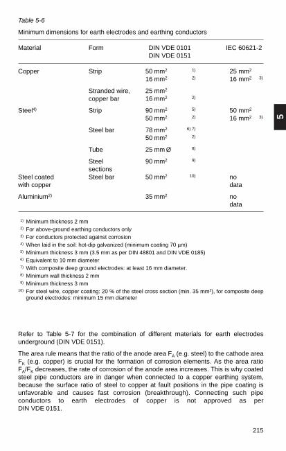
215
5
Table 5-6
Minimum dimensions for earth electrodes and earthing conductors
Material Form DIN VDE 0101 IEC 60621-2DIN VDE 0151
Copper Strip 50 mm2 1) 25 mm2
16 mm2 2) 16 mm2 3)
Stranded wire, 25 mm2
copper bar 16 mm2 2)
Steel4) Strip 90 mm2 5) 50 mm2
50 mm2 2) 16 mm2 3)
Steel bar 78 mm2 6) 7)
50 mm2 2)
Tube 25 mm Ø 8)
Steel 90 mm2 9)
sectionsSteel coated Steel bar 50 mm2 10) nowith copper data
Aluminium2) 35 mm2 nodata
1) Minimum thickness 2 mm2) For above-ground earthing conductors only3) For conductors protected against corrosion4) When laid in the soil: hot-dip galvanized (minimum coating 70 µm)5) Minimum thickness 3 mm (3.5 mm as per DIN 48801 and DIN VDE 0185) 6) Equivalent to 10 mm diameter7) With composite deep ground electrodes: at least 16 mm diameter.8) Minimum wall thickness 2 mm9) Minimum thickness 3 mm
10) For steel wire, copper coating: 20 % of the steel cross section (min. 35 mm2), for composite deepground electrodes: minimum 15 mm diameter
Refer to Table 5-7 for the combination of different materials for earth electrodesunderground (DIN VDE 0151).
The area rule means that the ratio of the anode area FA (e.g. steel) to the cathode areaFK (e.g. copper) is crucial for the formation of corrosion elements. As the area ratioFA/FK decreases, the rate of corrosion of the anode area increases. This is why coatedsteel pipe conductors are in danger when connected to a copper earthing system,because the surface ratio of steel to copper at fault positions in the pipe coating isunfavorable and causes fast corrosion (breakthrough). Connecting such pipeconductors to earth electrodes of copper is not approved as per DIN VDE 0151.

216 Table 5-7
Connections for different earth electrode materialsRatio of large area : small area ≥ 100:1
Material Material with large surface areawith small Steel, hot-dip Steel Steel Steel, hot-dip Copper Copper Copper, hot-dip Coppersurface area galvanized in concrete galvanized tin-plated galvanized with lead sheath
in concrete
Steel, hot-dip + + — + — — + +galvanized Zinc loss Zinc loss Zinc loss
Steel + + — + — — + +Steelin concrete
+ + + + + + + +
Steel +with lead sheath
+ +Lead loss
— + + +
Steelwith Cu sheath
+ + + + + + + +
Copper + + + + + + + +Coppertin-plated
+ + + + + + + +
Copper + + + + + +galvanized
+Zinc loss Zinc loss Zinc loss Zinc loss Zinc loss
+Zinc loss
Copper + + +with lead sheath
+ +Lead loss Lead loss
+ + +
+ Good for joining Can be joined— must not be joined

217
5
5.3.3 Dimensioning of earthing systems
The cross-section of earth electrodes and earthing conductors must be measured sothat in the event of a fault current IF (I"K1 in networks with low-resistance neutralearthing), the strength of the material is not reduced. The required cross-section maybe determined as follows:
tFA = IF · ———k
WhereIF : fault currenttf : duration of fault currentk : material coefficient
The material coefficient for copper is (see Sec. 5.1.3 for other materials)
ϑf — ϑ ik = 226 In (1 + ———————— ) A · s/mm2
234.5 °C + ϑ i
Where
ϑi : initial temperature in °C (maximum ambient temperature) ϑf: permitted final temperature
For the permissible final temperature see Table 5-8, (see also Sec. 13.1.1). Whereearthing conductors and PVC cables are laid on cable racks together ϑf must notexceed 150 °C.
Table 5-8
Permissible final temperatures in ° C for various materials
Material DIN VDE 0101IEC 60621-2DIN VDE 0100 Part 540
Cu bare 300 1) 500 2)
200 3)
150 4)
Al bare 300 1) 300 2)
200 3)
150 4)
Steel bare 300 1) 500 2)
or galvanized 200 3)
150 4)
Cu tin-plated 150 no dataor with lead sheath
1) If there is no risk of fire2) For visible conductors in locations that are not generally accessible3) For non-visible conductors in locations that are generally accessible4) Where hazards are greater
– for non-visible conductors in locations with increased fire risk– for earthing conductors laid together with PVC cables
The required standard cross-sections for bare copper depending on the single-line faultcurrent and fault current duration are given in Table 5-9.

218
Personnel safety in the event of malfunction is ensured when the step and touchvoltages do not exceed the limit values set in the standards (e.g. DIN VDE 0101).Step and touch voltages can only be calculated with the aid of computer programs in avery complex process.As per DIN VDE 0101, the touch voltages in outdoor installations are in compliancewhen the following three conditions are met simultaneously:1) Presence of a surface earth electrode surrounding the earthing system in the form
of a closed ring. Inside this ring there is an earthing grid (grid size ≤ 50 m × 10 m). Any station components outside the ring and connectedto the earthing system are provided with control earth electrodes.
2) Fault current duration ≤ 0.5 s 3) Earthing voltage UE ≤ 3000 v. The earthing voltage UE is the voltage that the entire earthing system has in the eventof malfunction compared to reference earth (∞ removed).
Table 5-9 Standard cross-sections
I“k 1 = I”k 33 Standard cross-sections for earthing material
2 + x0 /x1of copper in mm2
I“k 3 x0/x1I”k 1 ϑi = 30 °C, ϑf = 300 °C ϑi = 30 °C, ϑf = 150 °C
in kA in kA 1.0 s 0.5 s 0.2 s 1.0 s 0.5 s 0.2 s
1 80 — 4 × 95 2 × 95 — 4 × 120 4 × 7080 2 60 — 2 × 120 2 × 95 — 4 × 95 2 × 120
3 48 — 2 × 95 120 — 4 × 70 2 × 95
1 63 — 2 × 120 2 × 95 — 4 × 95 2 × 12063 2 47.3 — 2 × 95 120 — 4 × 70 2 × 95
3 37.8 — 2 × 95 95 — 2 × 120 2 × 70
1 50 — 2 × 95 120 — 4 × 70 2 × 9550 2 37.5 — 2 × 70 95 — 2 × 120 2 × 70
3 30 — 120 95 — 2 × 95 120
1 40 2 × 120 2 × 95 95 4 × 95 2 × 120 2 × 7040 2 30 2 × 95 120 95 2 × 120 2 × 95 120
3 24 2 × 70 95 70 2 × 95 2 × 70 95
1 31.5 2 × 95 120 95 2 × 120 2 × 95 12031.5 2 23.6 2 × 70 95 70 2 × 95 2 × 70 95
3 18.9 120 70 50 2 × 70 120 70
1 25 2 × 70 95 70 2 × 95 2 × 70 9525 2 18.8 120 70 50 2 × 70 120 70
3 15 95 70 35 120 95 50
1 20 120 95 50 2 × 95 120 7020 2 15 95 70 35 120 95 50
3 12 70 50 35 95 70 50
1 16 95 70 50 120 95 7016 2 12 70 50 35 95 70 50
3 9.6 70 50 35 70 50 35(continued)

219
5
Table 5-9 (continued)
Standard cross-sections
I"k 1 = I"k 33 standard cross-sections for earthing material of copper
2 + x0 /x1 in mm2
I"k 3 x0/x1I"k 1 ϑi = 30 °C, ϑf = 300 °C ϑi = 30°C, ϑf = 150 °C
in kA in kA 1.0 s 0.5 s 0.2 s 1.0 s 0.5 s 0.2 s
1 12.5 70 50 35 95 70 5012.5 2 9.4 50 35 35 70 50 35
3 7.5 50 35 35 70 50 35
1 10 70 50 35 95 70 35≤ 10 2 7.5 50 35 35 70 50 35
3 6 35 35 35 50 35 35
x0 /x1: Ratio of zero-sequence reactance to positive-sequence reactance of thenetwork from the point of view of the fault location; 1 for faults near thegenerator, heavily loaded networks and in case of doubt; 2 for all otherinstallations; 3 for faults far from the generator.
The earthing voltage UE in low-resistance earthed networks given approximately by:
UE = r · I"K1 · ZE
Wherer : reduction factorZE : earthing impedance I"K1 : single-line initial symmetrical short-circuit current
Overhead earth wires or cable sheaths connected to the earthing system carry some ofthe fault current in the event of malfunction as a result of magnetic coupling. This effectis expressed by the reduction factor r. If overhead earth wires or cable sheaths are notconnected, r = 1. In the case of overhead earth wires of overhead lines, the typicalvalues given in Table 5-10 apply.
Table 5-10
Typical values for earth wire reduction factors r
Earth wire type r
1 x St 70 0.971 x Al/St 120/20 0.801 x Al/St 240/40 0.702 x Al/St 240/40 0.60
The earthing impedance ZE is derived from the parallel switching of the dissipationresistance RA of the installation and the impedance ZP of parallel earth electrodes(cable, overhead cables, water pipes, railway tracks etc.). The following is approximate:
1 1 –1ZE = (—— + ——)RA ZP
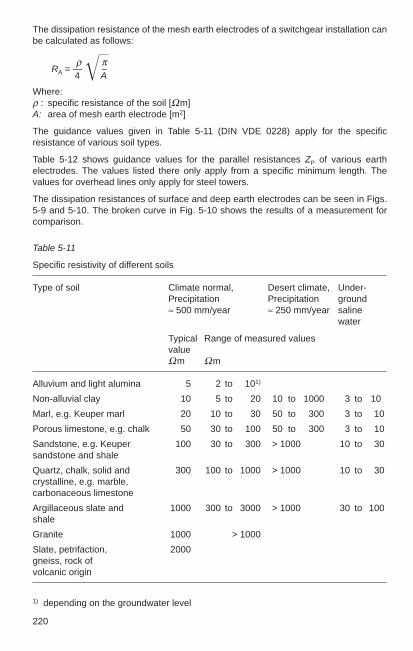
220
The dissipation resistance of the mesh earth electrodes of a switchgear installation canbe calculated as follows:
ρ πRA = — –
4 AWhere: ρ : specific resistance of the soil [Ωm] A: area of mesh earth electrode [m2]
The guidance values given in Table 5-11 (DIN VDE 0228) apply for the specificresistance of various soil types.
Table 5-12 shows guidance values for the parallel resistances ZP of various earthelectrodes. The values listed there only apply from a specific minimum length. Thevalues for overhead lines only apply for steel towers.
The dissipation resistances of surface and deep earth electrodes can be seen in Figs.5-9 and 5-10. The broken curve in Fig. 5-10 shows the results of a measurement forcomparison.
Table 5-11
Specific resistivity of different soils
Type of soil Climate normal, Desert climate, Under-Precipitation Precipitation ground≈ 500 mm/year ≈ 250 mm/year saline
water
Typical Range of measured valuesvalueΩm Ωm
Alluvium and light alumina 5 2 to 101)
Non-alluvial clay 10 5 to 20 10 to 1000 3 to 10
Marl, e.g. Keuper marl 20 10 to 30 50 to 300 3 to 10
Porous limestone, e.g. chalk 50 30 to 100 50 to 300 3 to 10
Sandstone, e.g. Keuper 100 30 to 300 > 1000 10 to 30sandstone and shale
Quartz, chalk, solid and 300 100 to 1000 > 1000 10 to 30crystalline, e.g. marble,carbonaceous limestone
Argillaceous slate and 1000 300 to 3000 > 1000 30 to 100shale
Granite 1000 > 1000
Slate, petrifaction, 2000gneiss, rock ofvolcanic origin
1) depending on the groundwater level

221
5
Table 5-12
Parallel resistances of earth electrodes
earth electrode type Zp Minimum length[Ω] [km]
overhead line with 1 earth wire St 70 3.2 1.8overhead line with 1 earth wire Al/St 120/20 1.3 4.2overhead line with 1 earth wire Al/St 240/40 1.2 5.4overhead line with 2 earth wires Al/St 240/40 1.1 6.810-kV cable NKBA 3 × 120 1.2 0.9Water pipe NW 150 2.3 1.5Water pipe NW 700 0.4 3.0Electric rail 1 track 0.6 8.0Electric rail 2 tracks 0.4 6.9
Fig. 5-9
Dissipation resistance RA of surface earthelectrodes (strip, bar or stranded wire) laidstraight in homogenous soil in relationshipto the length l with different specificresistivities ρE
Fig. 5-10
Dissipation resistance RA of deep earthelectrodes placed vertically inhomogenous soil in relationship to theelectrode length l with various diametersand specific resistivities ρE, curve x ... x:Measured values

222
5.3.4 Earthing measurements
The specific resistivity ρE of the soil is important for calculating earthing systems. Forthis reason, ρE should be measured before beginning construction work for aswitchgear installation; the measurements are made using the “Wenner Method” (F. Wenner: A Method of Measuring Earth Resistivity, Scientific papers of the Bureau ofStandards, No. 248, S. 469-478, Washington 1917).
Measuring the step and touch voltages after setup of a switchgear installation is oneway to confirm the safety of the system; the measurements are conducted inaccordance with the current and voltage method in DIN VDE 0101.
The current and voltage method also allows the earthing impedance (dissipationresistance) of the installation to be calculated by measuring the potential gradient.
Use of earth testers (e.g. Metraterr II) to measure dissipation resistance should berestricted to single earth electrodes or earthing systems of small extent (e.g. rod earthelectrode, strip earth electrode, tower earth electrode, earthing for small switchgearinstallations).
5.4 Lightning protection
Damage caused by lightning strikes cannot be completely prevented either technicallyor economically. For this reason, lightning protection facilities cannot be specified asobligatory.
The probability of direct lightning strikes can be greatly reduced on the basis of modelexperiments, measurements and years of observation with the methods describedbelow.
5.4.1 General
A distinction is made between external and internal lightning protection.
External lightning protection is all devices provided and installed outside and in theprotected installation provided to intercept and divert the lightning strike to the earthingsystem.
Internal lightning protection is total of the measures taken to counteract the effects oflightning strike and its electrical and magnetic fields on metal installations and electricalsystems in the area of the structure.
The earthing systems required for lightning protection must comply with DIN VDE 0101, with particular attention paid to the requirements for lightning protectionin outdoor switchgear (e.g. back flashover).

223
5
Key to symbols used
A live partB overhead earth wire
lightning rodC (m) distance between lightning rodsH (m) height of earth wire
height of lightning rod(height of interception device)
2H (m) twice the height of the earth wire3H (m) three times the height of the lightning rodh (m) height of live part over ground level (object height)hB (m) radius of lightning sphere, flashover distance to earthhx (m) lowest height of protected zone at midpoint between two lightning rodsL (m) distance overhead earth wire to equipment
distance lightning rod to equipmentLx (m) distance live part from axis of lightning rod
(protected distance)M centre of arc for limitation of outer protective zoneM1 centre of arc for limitation of inner protective zoneR (m) radius for M1-Brx (m) radius for limitation of protected zone at height hα shielding angle (with universal method)
5.4.2 Methods of lightning protection
There are currently four methods of designing lightning protection systems:
– Lightning sphere method– Method as per DIN VDE 0185– Linck’s universal method– Method as per DIN VDE 0101
Lightning sphere method
The lightning sphere method ensures complete lightning protection. It is used forresidential buildings or high-hazard locations (warehouses with highly flammablematerials such as oil, gas, cotton etc.). It is not used for electrical power systems.
The contours of the objects that are to be protected and the planned interceptiondevices are modeled – e.g. at a scale of 1:100 to 1:500. Then a sphere is made with ascale radius of 10, 20 or 40 m depending on the requirements, which corresponds tothe flashover distance to earth hB. The lightning sphere is then rolled around the modelon a flat surface. If the lightning sphere only touches the interception devices, theprotected objects are completely in the protected area. However, if the lightning spheredoes touch parts of the protected objects, the protection is not complete at thesesections (see Fig. 5-11).
If the configurations of the air terminals are simple, it will generally be unnecessary toproduce a model. The effectiveness of the protection system can be assessed byexaminations based on the projection of the lightning sphere.

224
Method as per DIN VDE 0185
The lightning protection method as per DIN VDE 0185 ensures that buildings arealmost fully protected. The structural features for the protected area are determined bythe above method and are generally the same as the method as per DIN VDE 0101.
Linck’s universal method
Linck’s universal method (see Fig. 5-12) provides the following data for the externallightning protection system (interception devices):– number and height of lightning rods and overhead earth wires,– theoretical location layout for interception devices.
Linck’s lightning protection method is based on the statistical data of the disconnectionfrequency in overhead cables.
Disconnecting of overhead lines caused by a direct lightning strike is based on twoeffects:– incomplete shielding by the earth wire,– back flashover.
Depending on the nominal voltage and the shielding angle of the building and overheadline, the back flashover is involved in the following percentages of all disconnections:
min. 0 %mean 25 % max. 50 %
When using Linck’s method to specify the permissible disconnection frequency forswitchgear installations, note that back flashover cannot occur in switchgearinstallations and the assumed disconnection frequency Y is conservative.
It is calculated as follows:– defining the required data,– preparing the input data,– calculation,– preparing design data.
Fig. 5-11
Determining the effectiveness of lightningrods and conductors for protecting thebuilding
Lightning sphere
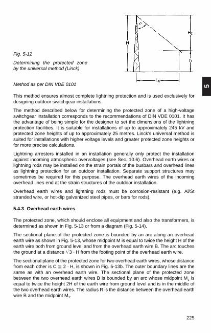
225
5Method as per DIN VDE 0101
This method ensures almost complete lightning protection and is used exclusively fordesigning outdoor switchgear installations.
The method described below for determining the protected zone of a high-voltageswitchgear installation corresponds to the recommendations of DIN VDE 0101. It hasthe advantage of being simple for the designer to set the dimensions of the lightningprotection facilities. It is suitable for installations of up to approximately 245 kV andprotected zone heights of up to approximately 25 metres. Linck’s universal method issuited for installations with higher voltage levels and greater protected zone heights orfor more precise calculations.
Lightning arresters installed in an installation generally only protect the installationagainst incoming atmospheric overvoltages (see Sec. 10.6). Overhead earth wires orlightning rods may be installed on the strain portals of the busbars and overhead linesas lightning protection for an outdoor installation. Separate support structures maysometimes be required for this purpose. The overhead earth wires of the incomingoverhead lines end at the strain structures of the outdoor installation.
Overhead earth wires and lightning rods must be corrosion-resistant (e.g. Al/Ststranded wire, or hot-dip galvanized steel pipes, or bars for rods).
5.4.3 Overhead earth wires
The protected zone, which should enclose all equipment and also the transformers, isdetermined as shown in Fig. 5-13 or from a diagram (Fig. 5-14).
The sectional plane of the protected zone is bounded by an arc along an overheadearth wire as shown in Fig. 5-13, whose midpoint M is equal to twice the height H of theearth wire both from ground level and from the overhead earth wire B. The arc touchesthe ground at a distance 3 · H from the footing point of the overhead earth wire.
The sectional plane of the protected zone for two overhead earth wires, whose distancefrom each other is C 2 · H, is shown in Fig. 5-13b. The outer boundary lines are thesame as with an overhead earth wire. The sectional plane of the protected zonebetween the two overhead earth wires B is bounded by an arc whose midpoint M1 isequal to twice the height 2H of the earth wire from ground level and is in the middle ofthe two overhead earth wires. The radius R is the distance between the overhead earthwire B and the midpoint M1.
Fig. 5-12
Determining the protected zone by the universal method (Linck)

226
The angle between the tangents to the two bounding lines is 2 × 30° at their point ofintersection. If an angle of around 2 × 20° is required in extreme cases, the distance1.5H must be selected instead of the distance 2H.
The arrangement of the overhead earth wires for a 245 kV outdoor installation is shownin Fig. 5-13 c. The bounding line of the protected zone must be above the live stationcomponents.
Fig. 5-13
Sectional plane of the protected zone provided by overhead earth wires as per the FGHrecommendations:a) sectional plane of the protected zone with one overhead earth wire, a) sectional plane of the protected zone with two overhead earth wires, c) arrangement of the overhead earth wires and protected zone of an outdoor
switchgear installation.

227
5
The height H of the overhead earth wire can be calculated from Fig. 5-14. The curvesshow the sectional plane of the protected zone one overhead earth wire.
Example: equipment is installed at a distance of L = 12.5 m from the overhead earthwire, with the live part at height h = 9.0 m above ground level: The overhead earth wiremust be placed at height H = 23.0 m (Fig. 5-14).
Fig. 5-14
Sectional plane of the protected zone for one overhead earth wire
5.4.4 Lightning rods
Experience and observation have shown that the protected zone formed by rods islarger than that formed by wires at the same height.
A lightning rod forms a roughly conical protected zone, which in the sectional planeshown in Fig. 5-15 a) is bounded by the arc whose midpoint M is three times the heightH of the rod both from ground level and the tip of the lightning rod. This arc touches theground at distance 5 · H from the footing point of the lightning rod.
The area between two lightning rods whose distance from each other is 3 · H formsanother protected zone, which in the sectional plane shown in Fig. 5-15 b) is boundedby an arc with radius R and midpoint M1 at 3 · H, beginning at the tips of the lightningrods.
m
H
Lm

228
Fig. 5-15
Sectional plane of the zone protected by lightning rods: a) sectional plane of theprotected zone with one lightning rod, b) sectional plane of the protected zone with twolightning rods.
Fig. 5-16
Sectional plane of the protected zone for two lightning rods
M1
M1
mC
H
m
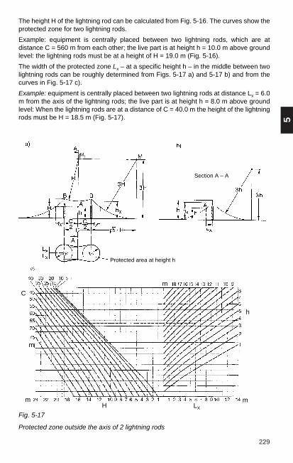
229
5
The height H of the lightning rod can be calculated from Fig. 5-16. The curves show theprotected zone for two lightning rods.
Example: equipment is centrally placed between two lightning rods, which are atdistance C = 560 m from each other; the live part is at height h = 10.0 m above groundlevel: the lightning rods must be at a height of H = 19.0 m (Fig. 5-16).
The width of the protected zone Lx – at a specific height h – in the middle between twolightning rods can be roughly determined from Figs. 5-17 a) and 5-17 b) and from thecurves in Fig. 5-17 c).
Example: equipment is centrally placed between two lightning rods at distance Lx = 6.0m from the axis of the lightning rods; the live part is at height h = 8.0 m above groundlevel: When the lightning rods are at a distance of C = 40.0 m the height of the lightningrods must be H = 18.5 m (Fig. 5-17).
Fig. 5-17
Protected zone outside the axis of 2 lightning rods
Protected area at height h
Section A – A
M1
m
m
C
h
mmH LX

230
5.5 Electromagnetic compatibility
The subject of electromagnetic compatibility (EMC) includes two fundamentallydifferent aspects of the effects of electromagnetic fields, i.e.– electromagnetic compatibility between electrical equipment and – the effects of electromagnetic fields on biological systems, particularly on humans.
Effects of electromagnetic fields on humans
Treatment of this part of the subject in the media has resulted in increased worry amongthe public, although there is no foundation for this, based on events in practice or anyrelevant research results.
The effects of electromagnetic fields on humans are divided into a low-frequency range(0 Hz to 30 kHz) and a high-frequency range (30 kHz to 300 GHz).
“Approved values” have already been established for both ranges. The low-frequencyrange is of primary interest for the operation of switchgear installations. The work ofstandardization in this area is still not complete. Currently there are:– the 26th federal regulations for the Federal Immission Control Act (26th BImSchV), in
force since 1 January 1997 for generally accessible areas without limitation on timeof exposure for fixed installations with voltages of 1000 V and above,
– DIN VDE V 0848-4/A3, published in July 1995 as a draft standard and– ENV 50166-1, a European draft standard from January 1995.
In the low-frequency range, the current density occurring in the human body is the decisive criterion for setting the limit values. According to a study by the WorldHealth Organisation (WHO), interaction between current and muscle and nerve cellsoccurs above a body current density of 1000 mA/m2, with proven acute danger to healthin the form of interference with the functioning of the nerves, muscles and heart. Thelowest limit for detection of biological effects is approximately 10 mA/m2. Currentdensities below 1 mA/m2 have no biological effects.
In 26th BImSchV, a body current density of 1-2 mA/m2 was selected as the basic valuefor the derivation of approved field quantities. At 50 Hz this yields permissible values of5 kV/m for the electrical field and 100 µT for the magnetic flux density.
Short-term higher values to double the permissible value are approved for both values.Higher values in a small space in the same dimensions are approved for the electricalfield outside buildings.
DIN VDE V 0848-4 and ENV 50166-1 specify a body current density of 10 mA/m2 as theinitial value for exposure in the workplace with limited exposure time. The associatedderived field quantities vary greatly depending on the exposure time. They aresignificantly higher than those specified by 26th BImSchV.
The approved limit values are set with close attention to the effects detected in the bodywith due consideration to high safety factors (250-500) with reference to the limit ofdirect health hazards. The current research results give no indication that lower valuesshould be specified as approved quantities with reference to the occurrences ofcancers.

231
5
TelecommunicationsequipmentDischarge
of staticelectricity
Broadcast radio
Service radio
Emission
Arc furnaces
Effect
Converters
Enviro
nmen
t
Switches
Coupling
Switchgearinstallation
Power equipment
NEMP
Lightning
Switches
Ripple-control
technology
Source
Electricalequipment
Sink
Arccontrol
Oscillationpacketcontroller
Therapysystems
Measuring
Process control
Feedback control
Computerized processes
Dataprocessing
Readings in the field taken under a 380 kV line at the point of greatest sag showed amagnetic flux density of 15 to 20 µT (at half maximum load) and an electrical fieldintensity of 5-8 kV/m. The corresponding values were lower with 220 kV and 110 kV lines. Electrical field intensities are practically undetectable outside metal-encapsulated switchbays, and the magnetic field intensity generally remains below thelimits of 26th BImSchV, even at full load.
Heart pacemakers may, but need not be influenced by electrical and magnetic fields. Itis difficult to predict the general sensitivity of pacemakers. When utilizing the approvedlimit value for workplace exposure, a careful case-by-case analysis is recommended.
Electromagnetic compatibility between electrical equipment
This part of the subject includes terms such as secondary lightning protection, precisionprotection and nuclear electromagnetic pulses (EMP or NEMP) and radio interferencesuppression. While these subjects are not treated in detail, this section deals with thephysical phenomena and the technical measures described in the following sections.
Electromagnetic compatibility is the capacity of an electrical device to functionsatisfactorily in its electromagnetic environment without influencing this environment,which includes other equipment, in a non-approved manner (DIN VDE 0870).
The electromagnetic environment of a device is represented by all the sources ofinterference and the paths to the device (Fig. 5-18). At the same time, theelectromagnetic quantities generated in the device also act on the environment throughthe same paths.
Fig. 5-18
Multilateral interference model

Electromagnetic compatibility (EMC) is essential at every phase of a switchgearinstallation project and extends from establishing the electromagnetic environment tospecifying and checking the measures required to maintaining control over planningand changes to the installation. The EMC activities are shown in Table 5-13.
232
Good electrical conductivity in the system is an essential basis for decouplingmeasures between the parts of the system and its environment to ensure equipotentialbonding and shielding.
Measures for equipotential bonding are combined under the term “bonding”. Allelectrical conductive parts of a system are connected to an earth. Conducting parts ofthe system can be conductively connected to this earth to enable operation of thesystem in accordance with regulations (bonding). If the earth is conductively connectedto an earth electrode (earthing), this is considered functional earthing(telecommunications, DIN VDE 0804) or system earthing (low-voltage systems).Functional earthing can also be implemented with protective functions (in connectionwith low-voltage) and must then be able to meet the corresponding requirements.
Table 5-13
Overview of EMC activities during the design of switchgear installations
EMC analysis– identifying sources of interference– determining interference quantities– calculating/estimating/measuring paths– determining the interference resistance of interference sinks
(e.g. from secondary equipment)
Measures for achieving EMC– measures at interference sources– measures on coupling paths– measures at interference sinks
Verification of EMC– generating interference quantities with switching operations– simulation of interference quantities in the laboratory
Particularly in the event of a fault, i.e. if there is non-permissible interference, thebilateral influence model as shown in Fig. 5-19 is sufficient to clarify the situation. Actionmust be taken to decouple the interference source and the interference sink.
Fig. 5-19
Bilateral interference model
Source
Emission Effect
ImmunityPower networksEarthing systemsCable runsConcentrated fields
SinkCoupling

233
5
Equipment housing that forms a part of the earthing system can be designed so it formsan equipotential envelope, which protects the equipment by shielding it againstincoming and outgoing interference fields.
Two important points must be observed when connecting conductive parts of electricalequipment during design of electrical installations:– protection against unacceptably high touch voltages by protective measures, as
specified by DIN VDE 0100 and 0101: a protective conductor system is used for thiswhen required.
– reduction of electromagnetic interference by creating equipotentials: this is thepurpose of the bonding system.
5.5.1 Origin and propagation of interference quantities
An electromagnetic interference quantity is an electromagnetic quantity that canindicate undesirable interference in an electrical system.
The interference quantity is a collective term that covers the actual physical terms ofinterference caused by voltage, current, signals, energy etc. (DIN VDE 0870).Interference quantities are caused by otherwise useful technical quantities or parts ofthem and by discharge of natural and technically generated static electricity. The term“interference” expresses the intention of considering the quantity in question in terms ofits possible interference effects.
Fig. 5-20 shows an overview of the most important interference sources in switchgearinstallations and their interference quantities and coupling paths.u
The behaviour of an interference quantity over time depends on the type of process thatcauses it and may be periodic or unique.
Periodic, sinusoidal interference quantities
They are referred to as ripple-control signals or carrier signals in data transmission andin general radio technology. Harmonics caused by the system voltage caused byignition processes (fluorescent lights, power supplies, power electronics) must also beconsidered. The actual cause of these harmonics is individual periodic switchingoperations of electronic devices. Each one of these switching operations can thereforebe considered as an interference quantity, which can be classified among the transient,pulse-type sources of interference described below.
Periodic, sinusoidal processes are shown in the frequency range resulting from aFourier series transformation, in the so-called amplitude spectrum as single lines. Theheight of these lines represents the proportion of a characteristic frequency, which iscontained in the sinusoidal interference signal. These frequency segments can also bedirectly measured (DIN VDE 0847 Part 1).
Transient, pulse-type interference quantities
These occur with switching operations with a more or less steep transition from oneswitch status to the other, in arc furnaces, in manually or electrically actuatedmechanical switches of the most varied power and in the semiconductors of power-electronic and computer equipment. A discharge process can also act as a generalpulse-type interference source. So both the discharge of static electricity, such asnatural lightning and the exposed conductive part discharge, and partial discharges ininsulation (transformers, transducers, machines) can be described as pulse processes.

234
Pulse-type, periodic processes, such as are generated by brush motorsasynchronously to the network frequency (“brush fire”), must also be classified astransient, pulse-type interference quantities when the individual processes areconsidered, in spite of a periodicity of the pulse sequences.
A unified and coherent representation of pulse-type interference quantities, includingtheir partial phenomena, is also possible in the amplitude density spectrum, which is derived from the Fourier series transformation and can also be measured (DIN VDE 0847 Part 1).
The interference quantities that originate with the very frequently occurring switchingoperations in the high-voltage area (primary side) of switchgear installations are listedin Table 5-14. They oscillate with high frequency.
Fig
. 5-2
0
Orig
in a
nd p
ropa
gatio
n of
inte
rfer
ence
qua
ntiti
es in
sw
itchg
ear
inst
alla
tions
.
Sw
itchi
ngev
ents
in th
e pr
imar
y ci
rcui
t
Ligh
tnin
gst
rike
on th
eh.
v. li
ne
Ligh
tnin
g st
rike
inea
rthed
sta
tion
com
pone
nts
Res
pons
e of
insu
latio
n
Con
duct
or-
born
e w
aves
Tran
smiss
ion
thro
ugh
inst
rum
ent
trans
form
er
Cur
rent
s vi
a ca
ble
shie
lds
Cur
rent
s vi
a ho
usin
gs
Mea
sure
men
tan
d pr
otec
tion
circ
uits
Con
trol
and
sign
al c
ircui
ts
Sec
onda
ry d
evic
e an
d se
cond
ary
syst
em
Rad
iate
dw
aves
Cur
rent
feed
into
the
earth
ing
syst
em
Mag
netic
field
s
Hig
h-fr
eque
ncy
field
s
Res
pons
e of
surg
e ar
rest
ers
Ear
th
faul
t
Sw
itchi
ng
even
ts in
the
seco
ndar
y ci
rcui
t
RT
tran
smis
sion
s
Inte
rfer
ence
sour
ce
Inte
rfer
ence
quan
tity
Cou
plin
gpa
th
Inte
rfer
ence
sink

235
5
SF6 disconnectorSelf-actuating
pressure switch
Quantity Voltage U Voltage UK E field H field Voltage U Voltage U E field H field
Rise time 4 – 7 ns 15 – 50 ns 50 – 100 ns 200 ns 180 – 700 ns 60 – 100 nsFrequency kHz – MHz – 20 MHz – 20 MHz kHz – MHz kHz – MHz
10 MHz
kV A kV AHeight system- system- 11) – 502) — 2.51) – 1252)— system- system- 53) – 504) — 13) – 24) —
specific specific m m specific specific m m
Damping weak strong strong strong strong strong strong strongGeometrical small large large largedistances
Table 5-14
Characteristic parameters of interference quantities with switching operations in the primary circuit of high-voltage installations
SF6 Gas-insulated switchgear (GIS) Conventional outdoor switchgear installation (AIS)
1) GIS with building 3) 345-kV breakers2) GIS without building 4) 500-kV breakers
E field
H fieldE field
H field

236
Fig. 5-21
Coupling mechanisms for interference quantities in a high-voltage switchgearinstallationUI1, UI2 components of longitudinal voltage, Uq transverse voltage➀ Capacitive coupling, CE capacitance of high-voltage conductor to earth grid,
CS1, CS2, CS3 capacitances of the secondary system conductor➁ Inductive couplings, H influencing magnetic fields, A1, A2 induction areas➂ Galvanic coupling, RE, LE resistivity and inductivity of the earth grid,
iE current in earth grid resulting from coupling over CE
➃ Radiation coupling➄ Surge waves from transient processes, Z1, Z2, Z3 wave impedances
Interference quantities propagate along the wires and by radiation: – galvanically, over the apparent resistances of conductors, – inductively coupled, – capacitively coupled, – as a common wave from two conductor systems, – as a free spatial wave.
Once coupled into the bonding system, earthing system or a signal circuit, theinterference quantity moves along the path of the conductor.
An interference quantity varies in time in the course of its propagation according to thecoupling between interference source and interference sink: – partial events may merge, – an event may be split into partial events.
The spectral energy density of the interference quantity causes the entire systemtransmitting it to oscillate; see Fig. 5-21, Coupling mechanisms for interferencequantities in a high-voltage switchgear installation.
Contr

237
5
Fig. 5-22
Relationships among potentials of an interference voltage:U12 symmetrical interference voltage componentU10, U20 non-symmetrical interference voltage componentsU0 asymmetrical interference voltage component
If an interference quantity is produced in a current circuit, its asymmetrical componentdisappears if the current circuit is structured and operated completely symmetrically.The asymmetrical component is the interference quantity, which may causeinterference in an isolated sink circuit.
If a conductor of the source current circuit is earthed, i.e. connected with referenceearth, its non-symmetrical component becomes very small while the other conductorassumes the symmetrical component as non-symmetrical. In this case, theasymmetrical component is about half the symmetrical.
An asymmetrical interference voltage component coupled to a sink current circuit has anon-symmetrical and a symmetrical component corresponding to the current circuit’snon-symmetry.
5.5.2 Effect of interference quantities on interference sinks
The origin of interference components at the input terminals of a device considered asan interference sink is determined by its design, the operating mode and the design ofthe connected line and also the device operated via the line.
a) Symmetrical operation:
Symmetrical operating mode for a current circuit occurs when its conductors haveequal impedances with respect to reference earth in the frequency range of the usefulquantity. Symmetrical operation is achieved by potential separation or the use ofdifferential amplifiers.
– The asymmetrical influence of the line acts equally on both wires of the line andgenerates non-symmetrical components in accordance with the earth relationshipsof the line terminals at the equipment. The difference of the non-symmetricalcomponents occurring at higher frequencies is a symmetrical component.
An interference quantity occurs in a current circuit (Fig. 5-22) whose conductors showearth impedances (primarily capacitance). This means that the interference quantityalso finds current paths to earth or reference earth. This yields the followinginterference voltage components:– symmetrical (differential mode, transverse voltage) between the conductors of the
current circuit– non-symmetrical between a conductor and earth or reference earth
– asymmetrical (common mode, longitudinal voltage) as resultant of non-symmetricalcomponents

238
– A symmetrical interference component in the high-frequency range occurs becauseof non-symmetries of the connected equipment on the asymmetrical coupling path,in the low-frequency range by couplings (inductive for finite area, capacitive for non-symmetrical configuration) in the conductor loop of the line.
– Direct non-symmetrical influence does not occur with symmetrical operation.
b) Non-symmetrical operation:
Non-symmetrical operating mode occurs when the conductors of a current circuit haveunequal impedances compared to the reference earth; this is always the case whenmultiple signal voltages have a common reference conductor.
The interference then affects each wire of the line separately. Particularly in the case ofinductive impedances within the equipment, the non-symmetrical interferencecomponent on the signal reference conductor is not always zero.
– The symmetrical interference component on the low-frequency range is equal to thenon-symmetrical component, and in the high-frequency range approximately equalto the non-symmetrical component.
– The asymmetrical influence has no meaning with non-symmetrical operation.
The ultimate effect of an interference quantity in equipment must be assessed in termsof voltage or current.
An interference effect in or even destruction of a semiconductor only occurs if a voltage(a current) exceeds a specific threshold value and then forms a sufficiently large pulse-time area.
Even if interference does not affect the functioning of an electronic circuit or stop it fromfunctioning, it is essential that the semiconductors used are not overstressed by theinterference quantity.
Semiconductors are destroyed by current spikes when exposed to pulsed events orthey are affected by cumulative damage until they eventually no longer have theproperties required for proper functioning of the device: dielectric strength, currentamplification and residual current.
An interference quantity can be superimposed on the useful signal as a symmetricalcomponent and can adversely affect the functioning in the influenced equipmentdepending on the interference distance (signal level – interference level) or sensitivity.
As a non-symmetrical component, the interference quantity can reach any part of thecircuit and result in spurious functions or affect the actual signal processing.
5.5.3 EMC measures
EMC must be planned quantitatively. This means that the interface requirements(emission, strength) must be specified for defined zones (EMC zones). Then thecompatibility level is defined, for which various types of decoupling measures arerequired. In this connection, the bonding system is particularly important.

239
5
The purpose of EMC measures is to reduce interference quantities at specific pointsbetween the site of origin (interference source) and the site of functional effect(interference sink), see Table 5-15.
Table 5-15
Application of EMC measures in a complete switchgear installation
Zone Source Coupling path Sink
Objective To reduce To reduce To enhanceInterference emission coupling interference
resistance
Technical Low-inductance Layout Filteringmeasure earthing Isolation Limitation
Equipotential bonding OptocouplerShielding
Wiring Balancingof relay coils Symmetrical operation
Non-electricaltransmission
Organizational Separation by coordinating operation processesmeasures Fault-tolerant programs and protocols
It is useful to assess the hierarchical elements of a systems, such as the complete plantequipment room
cubicle assemblyrack assembly
circuit boardcircuit section
componentwith respect to their multilateral compatibility in their various electromagneticenvironments; see Fig. 5-23.
Electromagnetic system environment
Interferencequantities
TransmissionSubsystem Subsystem
Subsystem
Cable run A – B
Equipment room A
Equipment room B
OVERALL SYSTEM
CubicleFig. 5-23
EMC zones in theirenvironment

240
Fig. 5-24
Meshed bonding system and treatment of shielding of secondary wiring in a high-voltage switchgear installation1)
1) ABB publication DSI 1290 88 D, reprint from “Elektrotechnik und Informationstechnik” 105 (1988):p. 357-370: Remde, Meppelink, Brand “Electromagnetic compatibility in high-voltage switchgearinstallations”.
The effectiveness of any measures must be assessed depending on the frequency; seeTable 5-16. The upper limit frequency for the effectiveness of a measure is limited bythe extension of the configuration for which they are used (Lambda/10 rule). Thisassessment must be applied to the length of earthing conductors, cable shields andtheir connections, to the side lengths and openings of shielding housings and to the gridsize of bonding systems.
Table 5-16
Limit frequencies for the effectiveness of measures
Zone Upper limit frequency Max. length
Switchgear installation 100 kHz 300 mBuilding 1 MHz 30 m
Equipment room 10 MHz 3 mCubicle 15 MHz 2 m
Device (rack – circuit board) 100 – 1000 MHz 30 – 3 cm
EMC measures should prevent or minimize the occurrence of symmetrical and non-symmetrical components. They are generally initially based on minimizing theasymmetrical component and with that, the symmetrical component. Measures againstthe asymmetrical component are bonding or ground-based. Measures for minimizingthe symmetrical component must be compatible with these.
Bonding-based EMC measures are shown in Fig. 5-24 with the example of an outdoorswitchgear installation. The following is assumed:
Instrumenttransformers
Switchbox/Relay building
Control centre

241
5
– secondary lines laid parallel to earth conductors– screening connected to ground at both ends by coaxial connection wherever
possible– additional equipotential bonding conductor over full length of line– multiple connection of building earth with the switchgear installation earth– multiple shield earth connection with increasing density in the direction of the
electronics, in accordance with the Lambda/10 rule– instrument transformer secondary circuit earthed only once per 3-phase group (in
local cubicle)
Decoupling measures
The interference level of an interference source acting on an interference sink can bereduced by a number of measures. In most cases, a single type of decoupling measureis not sufficient to achieve the required decoupling damping; several types of measuremust be applied in combination. Depending on the design in practice, the following listof options should be considered:
– Routing: lines of different interference sensitivity laid separately; minimum clearance,restriction of common lengths.
– Conductors: two-wire lines instead of common returns; symmetrical signal transmission withsymmetrical source and sink impedances.
– Potential isolation: galvanic isolation of the signal circuits at the system boundary; attention to parasiticcoupling properties of the isolating components.
– Shielding: for extensive compensation of galvanically coupled high-frequency potentialdifferences in the earthing system, generating a negative-sequence field withinductive influence and diversion of displacement currents with capacitive influence.
– Filtering: generally low-pass filter with concentrated components.
– Limitation: voltage-limiting components (surge arresters) to limit the voltage, but less influenceon steepness, source of new interference quantities because of non-linearity; morefor protection against destruction than to avoid functional deterioration.
– Equipotential bonding:for low-impedance connection of system or circuit sections between which thepotential difference should be as low as possible; basic requirement foreffectiveness of shielding, filtering and limitation.
Decoupling measures are only effective in restricted frequency ranges (see Fig. 5-25). This makes it all the more important to know what frequency range requires thegreatest decoupling damping. The greater the bandwidth of the decoupling is required,the more measures are required in the chain. The basic rule with the application ofdecoupling measures in the direction of propagation of the interference quantity is tobegin with the following:
– from the interference source to the environment with the decoupling of highfrequencies,
– from the environment to the interference sink with the decoupling of low frequencies.

242
Fig. 5-25
Effectiveness trend of decoupling measures with respect to preferred frequency ranges
Bonding system
The bonding system includes all equipment for electrically connecting the housing grounds, shield conductors, reference conductors where ever they are to be connected to the earth.
DIN VDE 0870 defines the terms for bonding and earthing. Bonding is most importantfor the requirements of EMC. It is the total of all electrically conductive metallic parts ofan electrical system, which equalizes different potentials for the relevant frequencyrange and forms a reference potential.
Note: The relevant frequency range covers both the functional and the environmentalfrequencies. This frequency range and the spatial extent of the electrical equipmentdetermine the achievable equipotential bonding and therefore the effectiveness of thebonding system. The bonding does not always cover the safety requirements of thepotential equalization.
The bonding can be connected with the earth (protective measures); this is the generalrule in switchgear installations.
Telecommunications equipment in particular can be operated with functional earthing.In this case, the earthing has the purpose of enabling the required function of anelectrical system. The functional earthing also includes operating currents of thoseelectrical systems that use the earth as a return.
An equipotential bonding between system parts intended for protection againstunacceptably high touch voltages and also for electromagnetic compatibility must havesufficiently low resistivity even in the high frequency range in which the line inductanceis dominant. This can be done by designing the bonding system as a meshconfiguration, which reduces the inductance by up to 5 times more than linear systems.The effectiveness of this measure is limited by the grid size for high frequencies (seeTable 5-16).
The leakage currents from limiters, filters and shielding must be considered in thedesign of a bonding system and coupling in signal circuits must be avoided.
Dec
oupl
ing
mea
sure
s InsulationConductor spacing
Electrical insulationOptocoupler
Shielded cable
Matching circuitsFilter
Circuit layoutShielded circuits
Limiters
Filter

243
5
Extended conductors, which of course include conductors for equipotential bonding,are also subject to electromagnetic interference quantities. Coupling anelectromagnetic wave carried by a line is reduced as the effective area of the conductorpicking up the interference increases. The inductive coupling with meshed conductorsis reduced by generating opposing fields around the conductors of the mesh.Therefore, meshed systems, combined with their effective capacitance, particularlywith the influence of the housing grounds installed over them, have an excellent stablepotential in whose vicinity the influence on the signal lines is low, similar to laying themin natural soil with its natural electrical properties.
The more extensive the design of a system, the more difficult is it to implement acontinuous ground plane. For this reason, such grounds are only hierarchical,correspondingly limit the EMC areas and must be consistently linked to the entirebonding system with consideration of their limit frequency. Potential differencesbetween the earths of subsystems distant from one another must be accepted. Thismeans that a non-symmetrical transmission of small signals of high bandwidth betweenthese subsystems may be subject to interference.
The bonding system set up with reference to EMC must be assessed according to thefollowing regulations:
– DIN VDE 0160 for heavy-current installations with electronic equipment– DIN VDE 0800 for the installation and operation of telecommunications systems
including data-processing systems– DIN VDE 0804 for telecommunications devices including data-processing devices
DIN VDE 0160 deals with the properties of the operational leakage currents (from allpractical busbar systems) that can occur in industrial power systems in the dataprocessing and heavy current subsystems.
In this case, a hierarchical, radial earthing design offers advantages for decoupling thesubsystems and systems with respect to interference.
DIN VDE 0800 and 0804 deal with the requirements of more extended data-processingsystems where the levels handled are generally of the same order of magnitude andinterference by common busbars is not anticipated, making it unnecessary to decouplethe busbars. This is advantageous for the treatment of the signal interfaces.
Systems and subsystems complying with the above regulations can be integrated intoan earthing/bonding concept if a bonding system with a superimposed protectiveconductor system is designed. The interface between the subsystems and theirenvironment is defined as follows:– protective conductor connection– bonding system connection.For more general reasons, structures intended for installation in systems (radial ormesh) may be specified for the bonding system. It is possible to use radialsubstructures in a meshed bonding system with no particular measures.
If a radial bonding system is specified (Fig. 5-26), the earths of the subsystems mustonly be connected together over the common equipotential bonding. This means thatthe following configurations are not permitted when signals are exchanged betweensubsystems:

244
Fig. 5-26
Two subsystems in a radial bonding system
Shielding
Cables are shielded to protect the internal conductors of the cable against interference,which can be coupled capacitively and inductively or galvanically (alternating values).With respect to the effect, the shielding must initially be considered as the influencedconductor. Coupling interference quantities in this conductor yields a current thatgenerates a voltage between the inner conductor and shield as a product of theshielding current and the complex shield resistance. The complex shield resistance isidentical to the shield-coupling resistance. The lower the shield resistance, the greaterthe decoupling effect of the shield. In practice, it is essential to include the resistance ofthe entire shield circuit, i.e. the shield connection, in the calculation.
A shield that is connected to reference earth at just one end only acts against thecapacitive interference. It then forms a distributed low-pass filter whose full capacitanceacts at the end of the line to which the shield is connected. The interference couplingtends to increase at the open end of the shield, which becomes particularly evident athigh interference frequencies.
If a shield can only be earthed at one end, this should always be the point of lowerinterference resistance. This is often the receiver, amplifier or signal processor side.
– shielding connected at both ends,
– signal exchange with reference to a common signal reference conductor connectedto the earth at both ends
– signal exchange over coaxial cable connected to earth at both ends.
This means that signal connections between subsystems must be configured in a radialbonding system to be always isolated.
Subsystem 1 Subsystem 2
Isolation channel 1
Isolation channel 2
Signal exchange
Equipotential bonding

245
5
A shield earthed at both ends, closes the current circuit around the area carrying amagnetic flux. A current that acts against the interference field according to the Lentzrule flows and so has a decoupling effect on the conductors of the shielded cable. Thiseffect can also be induced with non-shielded lines by using free wires or closely parallelearth conductors as substitute shields.
The assumption here is that the shielded line is not influenced by low frequency shieldcurrents resulting from equipotential bonding. This requirement is met by a bondingsystem that has sufficiently low impedances with the relevant frequencies. Forfrequencies where the external inductive component of the shield resistance issufficiently large compared to its real component, i.e. at high frequencies, a couplingcaused by potential difference is reduced to a value only induced by the transferimpedance.
The higher limit frequency of the shield effect depends on the length of the shieldbetween its connections to earth. Therefore, a shield must be connected to earth atshorter intervals, the higher the limit frequency of its effectiveness should be. Fig. 5-27shows typical methods of connecting shields for control cables.
Fig. 5-27
Methods of connecting shielded control cables: ˇˇˇˇˇˇˇˇˇˇˇˇˇˇˇˇˇˇˇˇˇˇˇˇˇˇˇˇˇˇˇˇˇˇˇˇˇˇˇˇˇˇˇˇˇˇˇˇˇˇˇa) coaxial (preferred) b) braided (less effective)
There are (fully insulated) devices with no connection to a protective conductor system.However, they have an inner shield for connection to the shield of the signal lines. Thisshield may carry interference voltages relative to its environment (“remote earth”).
The manufacturer’s directions for installation of all types of devices must be observed,without affecting the structure of the bonding system (DIN VDE 0160 or DIN VDE0800/0804).
Cable shields should always be connected at both ends. The ground connectionbetween the subsystems to be connected with the shielded cable should have a lowerresistance than the shield circuit. This is sufficient to prevent interference from bondingcurrents on the shield.
The relevant equipment can have a shield conductor rail (as per DIN VDE 0160) orspecial shield conductor terminals (as per DIN VDE 0800). Design in accordance withDIN VDE 0800 should be preferred for data-processing systems when considering the
a)
Shield contact union Terminal strip Terminal strip
Cableshield
Cableshield
Cablecores
Cablecores
Singleshields
Singleshields
Earth connection 1.5 mm2 (braid)
Shieldcontactring
Tohousing(earth)
Housing(earth)
Insulation Insulation
b)

246
possibility of interference. Where several systems interact, both bonding principles can be applied independently with reference to their shield connections, as shown inFig. 5-28.
Cable routing
Signal cables of control systems must always be laid separately from the generalinstallation network. However, power supply cables leading from a central distributionpoint to subsystems (e.g. peripheral devices) should be laid with the signal cables. – Aclearance of more than 0.3 m between the cables is sufficient for separate cable laying.
In the control rooms, the power supply lines are laid in a radial pattern from the low-voltage distributors to the various devices or subsystems. They are laid along theconductors of a bonding system that is meshed wherever possible.
Switch cabinets
The following information applies for proper design of switchbays with respect to EMC:– Wide-area, metallic conductive equipotential bonding of all metallic components of
the switchbox together is essential.– Use support plates, rails and racks of galvanized sheet steel only. Note: painted,
anodized or yellow-passivized components in some cases have very highresistance values above the 50 Hz frequency.
– Metallic components and parts inside the switchbay must be connected over a widearea and reliably. Ensure that appropriate contact material (screws andaccessories) is selected.
– Wide-area, low-resistance earthing of interference sources (equipment) on supportplates and racks prevents unwanted radiation.
Fig. 5-28
Shielding of systems as per DIN VDE 0160 and 0800:
1 shielding as per DIN VDE 0800, 2 shielding as per DIN VDE 0160 with busbars A toconnection of shield conductor, Z to connection of the signal reference conductor, PE to connection of protective conductor, 3 spatial bonding system(s)
1 2
3

247
5
– The cable layout inside the cabinet should be as close as possible to the referencepotential (cabinet ground). Note: freely suspended cables act preferably as activeand as passive antennas.
– Unused wires, particularly those of motor and power cables, should be placed onprotective conductor potential (PE) at both ends.
– Unshielded cables and wires of a circuit – i.e. feed and return – should be twistedtogether because of symmetrical interference.
– Relays, contactors and magnetic valves must be switched by spark suppressorcombinations or by overvoltage-limiting components. Line filters or interferencesuppression filters increase the interference resistance of the switchgear installationdepending on the interference frequency at the network input.
5.6 Partial-discharge measurement
Partial-discharge measurement is an important tool for assessing the status of high-voltage insulation. It is a proven technique for diagnosing errors in the laboratory, forquality assurance in production and on-site for all high-voltage equipment, such astransformers, instrument transformers, cable systems, insulating bushings and gas-insulated switchgear.
Partial discharges can damage solid insulation materials in the interior and on thesurface and may result in breakdown of the insulation. Partial discharges candecompose fluid and solid insulation.
Technical interpretation of the results obtained from the partial-dischargemeasurements enables detection of weak points at or in insulation systems andprovides information on the continuing availability of the equipment.
Partial discharges (PD) are low-energy electrical discharges, which bridge only part ofthe insulating clearance. They occur when the electrical strength between electrodes ofdifferent potential is exceeded at a localized point and result in brief discharges ofpartial capacities within insulation. These fleeting phenomena result in high-frequencyinterference fields. In practice, the operator should be aware of possible damage toinsulation, emission of electromagnetic interference fields (EMC) and the developmentof noise (corona).
Partial discharges may occur as follows:– in cavities inside solid insulation materials,– at unhomogenous points of the electrical field in solid, fluid and gas insulation
materials– in conductors without fixed potential and stray particles in the area of electrical
fields.
Some typical sources of partial discharges are shown in Fig. 5-29.
Partial discharges are verified by– electrical partial-discharge measurement,– acoustic partial-discharge measurement,– optical partial-discharge measurement,– chemical tests.
Electrical partial-discharge measurement is discussed below.

248
Fig. 5-29
Sources of partial discharge at electrodes, insulation and in gas
E0 = Feldstärkevektor = Metall = Fester Isolierstoff= ????= Metal or conductive materialE0=field intensity vector = solid insulation material

249
5
If alternating voltage u(t) is applied at the terminals of the equivalent circuit, the voltageat the capacitance of the cavity is found
C2u10 (t) = ———— Û · sin(ω t)
C1 + C2
Fig. 5-31 a shows the two voltage processes. If voltage u10(t) exceeds igniting voltageUZ of the gas-filled cavity, the spark gap F breaks down and the capacitance C1
discharges. The persistent voltage value on the test object is referred to as partialdischarge (PD) inception voltage. If the voltage on the test object u(t) exceeds thisvalue, the internal discharge will spark several times during a half-wave.
When C1 is discharged via F, pulse-shaped capactive charging currents i(t) – onlypartially fed from C3 but primarily from the external capacitances of the circuit – aresuperimposed on the network-frequency alternating current (Fig. 5-31 b). The
5.6.1 Partial discharge processes
There is a basic distinction between internal and external partial discharges.
Internal partial discharges
Internal partial discharges are gas discharges that occur in the cavities of solidinsulation material and in gas bubbles in fluid insulation material. This includesdischarges in cavities between insulation and electrode (Fig. 5-29 c) and within aninsulating body (Fig. 5-29 e).
Fig. 5-30 a shows a faulty insulating body. The non-faulty dielectric is formed by thecapacitances C’3, the gas-filled cavity by C1 and the element capacitances above andbelow the fault position by C’2. The replacement configuration of the insulating body isshown in Fig. 5-30 b. A spark gap F is placed parallel to the cavity capacitance C1. If thedisruptive discharge voltage of the gas-filled fault point is exceeded, it will break downand the capacitance C1 will be discharged.
Fig. 5-30
Configuration with internal partial discharges: a) material background b) equivalent c.t. circuit
a) b)
C’2
C1
C’2
C’3 C’3
test object

250
accumulation of impulses in the area of the zero crossings of voltage u(t) – generallyoverwhelmingly in the area after the zero crossings – is an indicator for discharges inthe cavities of solid insulation materials.
External partial discharges
If the field intensity at air-insulated electrode configurations (e.g. outdoor fittings) – suchas in the area before the sharp edges – exceeds the electrical strength of air as a resultof impulse ionization in the heavily loaded gas space electron avalanches andphotoionization will occur, ultimately resulting in partial breakdown of this area (trichelimpulses).
Figs. 5-32 a and b shows a simplified view of the processes with the associatedequivalent circuit. In the diagram, C1 represents the gas space through which the partialdischarge breaks down and resistance R2 represents the charge carriers formed beforethe peak, which move around in the field cavity and result in a degree of conductivity.
Fig. 5-31
a) voltage characteristics in the equivalent-circuit diagram for pulse-type internalpartial discharges
b) current characteristics in the equivalent-circuit diagram for pulse-type internalpartial discharges
a) b)
Fig. 5-32
Configuration with external partial discharges: a) peak plate configuration b) equivalent-circuit diagram c) voltage characteristics in the equivalent-circuit diagram for pulse-typeexternal partial discharges.

251
5
The associated voltage characteristics of the configuration are shown in Fig. 5-32 c.Thevoltage characteristic u10(t) at C1 before the beginning of the first partial dischargefollows the equation
Û πu10 (t) = ———— sin(ωt – — )
ωC1 R2 2
The response of the spark gap F in the equivalent-circuit diagram shows the pulse-shaped partial breakdown. If the voltage at the test object is sufficiently high over a timerange, the result is a number of PD impulses per half-wave. An indication of externalpartial discharges on sharp-edged electrodes is the accumulation of impulses in therange of the peak values of the external voltage u(t) applied at the fittings.
5.6.2 Electrical partial-discharge measurement procedures
Electrical partial-discharge measurement according to IEC 60270 (DIN VDE 0434)
In the course of almost 40 years of use with simultaneous intensive development of theprocedures, this procedure, which is based on the measurement of the apparentcharge of the PD impulses at the test object terminals, has become very widespread inthe area of high-voltage installations and devices.
Three different test circuits can be used (Fig. 5-33). The coupling capacitor CK and thefour-terminal coupling circuit Zm (and Zm1) are required for partial-dischargemeasurement. Impedance Z protects the high-voltage test source and acts as a filteragainst interference coupled from the network.
The high-frequency high-capacity charging current resulting from the partial dischargesin the test object feeds the test object capacitance Ca from the coupling capacitance CK.Therefore, ratio CK/Ca determines which charge component at four-terminal couplingcircuit Zm can be measured, i.e., CK determines the sensitivity of the PD measurement.The quantitative evaluation of the partial-discharge measurement is based on theintegration of the high-capacity charging current. This is integrated in the partialdischarge instrument within a fixed frequency band.
With respect to the strong influence of the test object and the instrumentation on theresult, the test circuit must be calibrated before every test cycle with the test objectconnected. During this process, a calibration pulse generator feeds defined chargeimpulses to the terminals of the test object.
The partial discharge instrument gives the apparent charge as a numerical value withthe dimension pC (pico-coulomb) as the result of the measurement. The phase angleof the partial charge impulses based on the applied test voltage is also significant.Different displays are shown on monitors for this purpose. Modern devices show theamplitude, rate of occurrence, frequency and phase angle at a specific voltage in acolour image (Fig. 5-34).
The test circuit as shown in Fig. 5-33a is preferred for measurements in practice. In thecase of laboratory measurements where the test object is isolated from ground, the testcircuit as shown in Fig. 5-33b is suitable.
The partial-discharge measurement technology distinguishes between narrow-bandand broad-band partial-discharge measurement. This classification is based on thefrequency segment in which the partial discharges are recorded. While measurementwith the narrow-band measurement in an adjustable frequency band is done withselected mid-frequency, the broad-band method covers a frequency range of 40 kHz to

252
800 kHz. Interference couplings are a particular problem, as they tend to occur inmeasurements on site as a result of a lack of shielding. There are now a number ofcountermeasures for this, such as narrow band measurements and active gate circuits.Another method is to use the bridge test circuit shown in Fig. 5-33 c.
Partial discharges within encapsulated switchgear installations are frequently locatedby acoustic partial-discharge measurement in addition to electrical partial-dischargemeasurement. It reacts to the sound energy that is generated by partial-dischargeactivity. Sensitive sensors, such as parabolic mirrors and structural sound pickups,detect these sounds in the frequency range between 20 kHz and 100 kHz.
UHF measurement
The PD impulse in SF6-isolated high-voltage installations has a wide frequency
Fig. 5-33
Basic circuit from IEC Publication 60270: a) + b) direct measurement c) bridge measurement
a)
b)
c)
Alternative position for Zm
Z
U ~Ca
Ck
ZmZm
ZmZm
CkCa
Z
U ~
U ~Zm
Zm Zm1Zm1
Ca
Z
Ca1 (Ck)

253
5
Fig. 5-35
Cone sensor in the flange of a GIS
spectrum up to the GHz range. The electromagnetic waves generated in this processspread inside the encapsulation in the form of travelling waves. They can be detectedusing capacitive probes integrated into the encapsulation (Fig. 5-35) and used to locatethe fault positíon.
However, this requires several probes in one installation, and also the laws of travellingwave propagation, including the effects of joints (such as supports) and branching mustbe taken into account in the interpretation.
Fig. 5-34
Characteristic partial-discharge image
Sensor electrode ascircuit-disc antenna
Sensor terminal
Flange opening
Conical infeed line
Terminal wire 50 Ω measurement line
26.67 pC
0.00 pC
–26.67 pC360°180°

254
The characteristic partial-discharge images formed with UHF measurement are similarto those formed by conventional measurement. The measurement sensitivity is notdetermined with a calibration pulse generator but by applying a voltage to one of theUHF PD probes to determine the transmission function of the installation, including theother PD probes.
One great advantage of the UHF measurement (Ultra High Frequency, 300 MHz to 3 GHz) is the significant decrease of external interference in this frequency range.
UHF measurement by permanently installed probes is particularly suited for monitoringhigh-voltage installations during operation. Measurements can be made continuouslywhile storing the measured values or at regular intervals (monitoring).
5.7 Effects of climate and corrosion protection
The operational dependability and durability of switchgear installations and theircomponents are strongly influenced by the climatic conditions at their place ofinstallation.
There are two aspects to the demand for precise and binding specifications for theseproblems:– The description of the climatic conditions to be expected in service and also during
storage, transport and assembly.– The specification of the test conditions or design requirements that ensure reliable
functioning under defined climatic conditions.
5.7.1 Climates
The standard DIN EN 60721-3, “Classes of environmental influence quantities and theirlimit values”, is a comprehensive catalogue of classes of interconnected environmentalfactors. Every class is identified with a three-character designation as follows:
1st place: type of product use(1 = storage, 2 = transport, 3 = indoor application, 4 = outdoor application etc.)
2nd place: type of environmental influence
(K = climatic conditions, B = biological conditions, C = chemically active substancesetc.)
3rd place: assessment of the severeness of the environmental influences (higherfigures = more difficult conditions)
For example, class 3K5 can be considered for applications of indoor switchgearinstallations in moderate climate zones. It indicates a total of 16 parameters of differentclimatic conditions. The most important are summarized in Fig. 5-36 in the form of aclimatic diagram.
It must not be assumed that one or even more of the given limit values will occur inservice continuously; on the other hand it is also assumed that they will be exceededfor a short period or in rare cases, but with a probability of < 0.01.
The classification of environmental conditions only provides manufacturers and usersof electrotechnical products with an orientation and a basis for dialogue. The IEC committees responsible for the product groups are expected to use them as a basis

255
5
Fig. 5-36
Climatic service conditions for indoor switchgearClimate diagrams as per DIN EN 60721-3 for class 3K5and as per DIN EN 60694 for class “Minus 5 indoor”
Rel
ativ
e hu
mid
ity
3K 5
Minus 5indoor
Absolute humidity
g/m
3
Air temperature °C
%

256
Table 5-17
Normal and special climatic service conditions for indoor applicationN = normal service conditions (with variations N1, N2 etc.)S = special service conditions
High-voltage Low-voltageswitchgear and switchgear
Environmental influence controlgear assembliesDIN EN 60694 DIN EN 60439-1(VDE 0670 Part 1000) (VDE 0660 Part 500)
Minimum temperature N1: – 5°C N: – 5°CN2: – 15°CN3: – 25°CS: – 50°C/+ 40°C
Maximum temperature N1: + 40°C N: + 40°CN2: + 35°C (24h average)S: + 50°C/– 5°C
Relative humidity N: 95% (24h average) N: 50% at 40°CN: 90% (monthly average) N: 90% at 20°CS: 98% (24h average)
Water vapour partial pressure1)N: 2.2 kPa (24h average)N: 1.8 kPa (monthly average)
Condensation occasional occasional
Solar radiation negligible N: noneS: present, caution!
Installation height N: ≤ 1000 m ≤ 2000 m2)
S: > 1000 m(with dielectriccorrection)
1) 2.2 kPa = 22 mbar = 16 g/m31.8 kPa = 18 mbar = 12 g/m3
2) > 1000 m special agreement for electronic equipment
for unified specifications for normal and special service conditions. Tables 5-17 and 5-18 show the corresponding specifications in the product standards DIN EN 60694(VDE 0670 Part 1000) – High-voltage switchgear and controlgear3) – and DIN EN 60439-1 (VDE 0660 Part 500) – Low-voltage switchgear assemblies.
These standards also include specifications regarding additional environmentalconditions such as contamination, oscillations caused by earthquakes, technicallyoriginated external heat, electromagnetic influence etc.
3) Compare the climatic diagram (Fig. 5-36).

257
5
Table 5-18
Normal and special climatic service conditions for outdoor applicationN = normal service conditions (with variations N1, N2 etc.)S = special service conditions
High-voltage Low-voltageswitchgear and switchgear
Environmental influence controlgear assembliesDIN EN 60694 DIN EN 60439-1(VDE 0670 Part 1000) (VDE 0660 Part 500)
Minimum temperature N1: –10 °C N1: –25 °CN2: –25 °C N2: –50 °CN3: –40 °CS: –50 °C/+ 40 °C
Maximum temperature N1: +40 °C N: +40 °CN2: +35 °C (24h average) +35 °C (24h average)S: +50 °C/–5 °C
Condensation and are to be 100 % rel. humidityPrecipitation considered at +25 °C
Solar radiation 1000 W/m2 N: –––S: If present, caution!
Ice formation N1: 1 mm thicknessN2: 10 mm thicknessN3: 20 mm thickness
Installation height N: ≤ 1000 m ≤ 2000 m1)
S: > 1000 m(with dielectriccorrection)
1) above 1000 m special agreement for electronic equipment
Switching devices, including their drives and auxiliary equipment, and switchgearinstallations must be designed for use in accordance with their ratings and the specifiednormal service conditions. If there are special service conditions at the installation site,specific agreements are required between manufacturer and user.

258
Climatic conditions
High/lowtemperatures– friction at
bearings– viscosity of
hydraulicfluid
– flowresponse of gases
Precipitation(rain, hail,
snow)
Condensationof
humidity
Ice formation
Mechanicalsequence of
switchingoperations
Insulationcapacity
Mechanicalstrength
SurfacecharacteristicsCurrent pathresistances
High operating
temperatureHeat
resistance
Low operatingtemperature
Impact strength
Rusting of parts
& housings of steel
Oxidization ofCu and
Al contacts
Influence
Danger
Endangeredproperty
Fig. 5-37
Ways that switchgear and installations are affected by climatic conditions
5.7.2 Effects of climate and climatic testing
Fig. 5-37 uses examples to indicate the variety of influences possible on switchgear inservice resulting from climatic conditions. The development and manufacture of devicesand installations that resist these influences require considerable experience.Additional security is provided by conducting appropriate tests based on the relevantproduct standards. The following are some examples:– Wet-test procedure of the external insulation of outdoor switchgear as per DIN IEC
60060-1 (VDE 0432 Part 1)– Limit temperature tests of high voltage circuit-breakers as per DIN VDE 0670-104
(VDE 0670 Part 104)– Switching of disconnectors and earthing switches under severe icing conditions as
per DIN EN 60129 (VDE 0670 Part 2)– Testing of indoor enclosed switchgear and controlgear (1 kV to 72.5 kV) for use under
severe climatic conditions (humidity, pollution) as per IEC Report 60932.

259
5
5.7.3 Reduction of insulation capacity by humidity
The reduction of insulation capacity by humidity is particularly significant on the surfaceof insulators. With outdoor devices, humidity results primarily from precipitation, suchas rain, hail, snow, while in the case of air-insulated indoor switchgear and inside gas-insulated installations (GIS), the problem is condensation from moisture that waspreviously a component of the ambient gas or the atmosphere.
The moisture content of a gas mixture can be expressed in different ways. From thephysicist’s point of view, the scale for the fractions of the components of a gas mixtureis the partial pressures. The partial pressure of a component is the pressure that ismeasured at a given temperature if this component is the only constituent of the totalvolume of the mixture. In the event of unintended admixtures, as observed here,the partial pressure of water vapour varies in the mbar range or when considered asabsolute moisture in the range of a few g/m3. Another possibility of expressing themoisture content quantitatively is to determine the “dew point”, i.e. the temperature atwhich condensation occurs. This information is the most meaningful for the switchgearoperator. Fig. 5-38 shows the relations.
The sequence of the reduction of insulation capacity by moisture is the same for allthree types of insulator surfaces: Initially only a very slight current flows over thehumidity film along the insulator surface because of the very low conductivity of thepure water of the film. Partial discharges along the current path yield decompositionproducts that continually increase the conductivity until the insulator surface ispermanently damaged or a flashover occurs. Any outside contamination that is presentalready in the beginning significantly accelerates the deterioration process.
Countermeasures for outdoor switchgear are limited to the selection of material(ceramic, glass, cycloaliphatic resins, silicone rubber) and the selection of the creepagedistance (cf. DIN EN 60071-2 (VDE 0111 Part 2)). Usage of specific minimum lengthsfor creepage paths and also material selection are also very important for indoorinsulation in atmospheric air. However, condensation can also be prevented if requiredby the use of air-conditioning or by raising the temperature slightly inside switchbaysand cubicles with small anticondensation heaters.
In the case of gas-insulated switchgear (GIS), the problem is different. The moisturecontent of the insulating gas is not due to climatic conditions but is primarily brought inas the moisture content of solid insulation materials and only gradually transferred tothe insulation gas. The installation of drying filter inserts with sufficient moisture-absorbing capacity has been found to be a suitable means of keeping the moisturecontent of the gas or the dew point low (≤ –5°C).

260
Fig. 5-38
Relation between water-vapour partial pressure, absolute humidity and dew point10 mbar = 1 kPa
g/m3mbar
22
10
Wat
er v
apou
r p
artia
l pre
ssur
e
16
10
Ab
solu
te h
umid
ity
100 100
Dew point

261
5
5.7.4 Corrosion protection
Design regulations for preventing corrosion are not included in national andinternational standards. They are a part of the manufacturer’s experience and can befound in internal documents and also occasionally in the supply regulations ofexperienced users. The following are examples of proven measures:
– Painting and galvanizing sheet metal and sections of steel, aluminium and stainlesssteel (Fig. 5-39)Note: Top-coat varnishing can be done in one pass with the powder-coating processapplied to the appropriate thickness instead of several wet-coating passes.
– Structural components of mechanical drives and similar of steel, which are requiredto meet close tolerances or antifriction properties, such as shafts, latches andguideways, can be effectively protected from corrosion for use indoors by manganeseor zinc phosphor treatment (5-8 µm) concluded by an oil bath.
– Structural components of steel which are not subjected to any specific mechanicaldemands and standard parts are generally galvanized with zinc (12 µm) and thenchromatized (passivization).
– Conductor materials such as copper and aluminium must be silver galvanized (20µm) in contact areas with spring-loaded contacts. Aluminium requires application of acopper coating (10 µm) before the silver is applied. A silver coating of about 20 µmhas the optimum resistance to mechanical friction.The appearance of dark patches on silver surfaces is generally no reason forconcern, because the oxidation products of silver are conductive and this will notgreatly affect the conductivity of the contact. The oxidation products of copper arenon-conductive, so oxidation on copper surfaces can easily result in an increase inthe temperature of the contact and then result in serious problems.Oxidation gradually reduces the thickness of the silver coating. Under normal indoorconditions, climatic influences will not generally result in complete loss of the silvercoating. However, this must be taken into consideration in industrial premises withparticularly chemically aggressive atmospheres. Under these circumstances it maybe necessary to use partially gold-plated contacts, even in the area of powerengineering.

262
Fig. 5-39
Surface treatment and coating for switchgear installations
Switchgear enclosures and housings
Sheet steel Steelsections
Rustremoval
Galvanize
Degreasing
Primer coat: dry film 30 µm
1st top coat: dry film 30 µm
2nd top coat: dry film 30 µm
Indoor and outdooroccasional condensationwarm dry climate
Indooroccasionalcondensationwarm dry climate
Indoor and outdooraggressive atmospherewarm humid climate
3rd top coat: dry film 30 µm
Phosphatize
AlZnsheet steel Aluminium Stainless
steelMaterial
Pretreatment
FinishSuitable for

263
5
Layout of the IP Code
IP 2 3 C H
Code letters(International Protection)
First digit(0 to 6 or letter X)
Second digit(0 to 8 or letter X)
Additional letter (optional)(Letters A, B, C, D)
Supplementary letter (optional)(Letters H, M, S, W)
If a code digit is not required, it must be replaced by the letter “X” (“XX”, if both digits arenot used).
5.8 Degrees of protection for electrical equipment of up to 72.5 kV (VDE 0470 Part 1, EN 60529)
The degrees of protection provided by enclosures are identified by a symbol comprisingthe two letters IP (International Protection), which always remain the same, and twodigits indicating the degree of protection. The term ”degree of protection” must be usedto indicate the full symbol (code letters, code digits).

264
Table 5-19
IP - degrees of protection
Component Digits Significance for protection Significance foror letters of the equipment protection of persons
Code letters IP – –-
0 not protectedProtection againstaccess
Protection against to hazardousingress of solid bodies parts with
1 ≥ 50 mm diameter back of the handFirst digit 2 ≥ 12.5 mm diameter fingers
3 ≥ 2.5 mm diameter tools4 ≥ 1.0 mm diameter wire ≥ 1.0 mm Ø5 dust-protected wire ≥ 1.0 mm Ø6 dustproof wire ≥ 1.0 mm Ø
0 not protectedProtection againstingress of water with harmful effects for
1 vertical drops2 drops (15 ° angle)
Second digit 3 spray water4 splash water5 jet water6 strong jet water7 temporary immersion8 continuous immersion
Protection againstaccess to hazardousparts with
Additional A back of handletter B finger(optional) C tool
D wire (1.0 mm Ø, 100 mm long)
Supplementary information especially forSupplementary H High-voltage devicesletter M Movement during water test –(optional) S Stationary during water test
W Weather conditions
Examples for application of letters in the IP code
The following examples are intended to explain the application and the configuration of letters in the IP code.
IP44 – no letters, no optionsIPX5 – first digit omittedIP2X – second digit omittedIP20C – use of additional lettersIPXXC – omission of both digits, use of the additional letterIPX1C – omission of the first digit, use of the additional letterIP2XD – omission of the second digit, use of the additional letterIP23C – use of the supplementary letterIP21CM – use of the additional letter and the supplementary letterIPX5/ – indication of two different protection classes by one housing againstIPX7 – jet water and against temporary immersion for “versatile” application.

265
6
6 Methods and aids for planning installations
6.1 Planning of switchgear installations
6.1.1 Concept, boundary conditions, pc calculation aid
The process of planning switchgear installations for all voltage levels consists ofestablishing the boundary conditions, defining the plant concept and deciding theplanning principles to be applied.
The planning phase is a time of close cooperation between the customer, the consult-ing engineer and the contractor.
The boundary conditions are governed by environmental circumstances (plant location,local climatic factors, influence of environment), the overall power system (voltagelevel, short-circuit rating and arrangement of neutral point), the frequency of operation,the required availability, safety requirements and also specific operating conditions.
Table 6-1 gives an indication of the boundary conditions which influence the designconcept and the measures to be considered for the different parts of a switchgearinstallation.
In view of the equipment and plant costs, the necessity of each measure must also beexamined from an economic standpoint.
Taking the busbar concept as an example (Table 6-3), the alternatives are evaluatedtechnically and economically. The example is valid for h.v. installations, and to someextent m.v. installations as well.
PC calculation aid
Numerous computer programs are available for use in planning switchgearinstallations, particularly for design calculation. Sections 6.1.5 to 6.1.7 deal withcomputer-aided methods for:
– short-circuit current– cable cross section– cable routing.
Table 6-2 summarizes the computer programs used in planning switchgearinstallations, together with their fields of application and contents.

266
Table 6-1
Choice of plant concept and measures taken in relation to given boundary conditions
Boundary conditions Concept and measures
Environment, climate, Outdoor/indoorlocation: Conventional/GlS/hybrid
Equipment utilizationConstructionProtection class of enclosuresCreepage, arcing distancesCorrosion protectionEarthquake immunity
Network data,network form: Short-circuit loadingsProtection conceptLightning protectionNeutral point arrangementInsulation coordination
Availability and redundancy Busbar conceptof power supply: Multiple infeed
Branch configurationStandby facilitiesUninterruptible suppliesFixed/drawout apparatusChoice of equipmentNetwork layout
Power balance: Scope for expansionEquipment utilizationInstrument transformer design
Ease of operation: Automatic/conventional controlRemote/local controlConstruction/configuration
Safety requirements: Network layoutArcing fault immunityLightning protectionEarthingFire protectionTouch protectionExplosion protection

267
6
Table 6-2
Computer programs for project planning and calculations for switchgear installations(CAD programs, see Section 6.3.3)
Program Application area Testing, determination, dimensioningName
EMTP Calculation of transient – Internal and external overvoltagesprocesses in any meshed – Interference voltage affectingmultiphase electrical telecom cablessystems – Transient voltage elevation in
earthing systems on lightningstrike
– Operational response of batterypower systems
PPCP Calculation of potential- – Determination of the propagationcourse in earthing systems resistance
– Determination of step andtouch voltages
STÖRLI Calculation of the pressure – Checking the pressure resistancecharacteristic in switchgear of medium-voltage switchgearrooms on arcing rooms
– Dimensioning pressure reliefequipment
KURWIN Dynamic resistance – Static resistance and thermal anddynamic short-circuit currentcapability of switchgear installations with conductor cables and tubularconductors as per DIN EN 60865-1(VDE 0103)
ROBI Static resistance – Deflection line and torque curve of waves and tubular conductors
CALPOS® Programming system for net-work calculation with the followingmodules:Phase fault current calculation; – Switchgear installations (busbars,calculation of symmetrical and connections)non-symmetrical fault currents – Equipment (switches, transformers)as per– DIN VDE 0102/IEC60909 – Protection devices– Superposting method
Load flow calculation – Switchgear installations– Equipment and power– Minimum loss system operation
methods– Critical system states– Directed switchovers after
equipment failure– Voltage drop on motor startup
(continued)

268
Table 6-2 (continued)
Computer programs for project planning and calculations for switchgear installations(CAD programs, see Section 6.3.3)
Program Application area Testing, determination, dimensioningName
CALPOS® Selectivity analysis (over- – Checking protection coordinationcurrent protection) in MS and NS networks
Distance protection – Protection coordination of cableunits
– Creation of selective tripping schedules
Harmonic analysis – Harmonic currents and voltages in networks with converters
– System perturbation by harmonics– Compensation equipment– Propagation of audiofrequency
ripple control signals
Dimensioning of earthing – Cross sections for earthingsystems (VDE 0141, IEEE 80) material
– Hazardous voltages
Dimensioning low-voltage – Specification of cable typecables – Maximum length
– Selection of protective devices
Motor startup – Dynamic simulation in the timerange
Dynamic network simulation – Investigation of system response todynamic processes
CALPOS® – Ramses – Determination of reliabilityquantities in networks
CALPOS® – Main – Determining an optimummaintenance strategy for installationequipment

269
6
6.1.2 Planning of high-voltage installations
The following criteria must be considered when planning high-voltage switchgear in-stallations:
Voltage levels
High-voltage installations are primarily for power transmission, but they are also usedfor distribution and for coupling power supplies in three-phase and HVDC systems.Factors determining their use include network configuration, voltage, power, distance,environmental considerations and type of consumer:
Distribution and urban networks > 52 – 245 kVIndustrial centres > 52 – 245 kVPower plants and transformer stations > 52 – 800 kVTransmission and grid networks 245 – 800 kVHVDC transmission and system interties > 300 kVRailway substations 123 – 245 kV
Plant concept, configuration
The circuitry of an installation is specified in the single-phase block diagram as thebasis for all further planning stages. Table 6-3 shows the advantages anddisadvantages of some major station concepts. For more details and circuitconfigurations, see Section 11.1.2.
The availability of a switching station is determined mainly by:
– circuit configuration, i. e. the number of possibilities of linking the network nodesvia circuit-breakers and isolators, in other words the amount of current path re-dundancy,
– reliability/failure rate of the principal components such as circuit-breakers, isolatorsand busbars,
– maintenance intervals and repair times for the principal components.
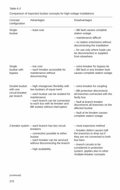
270
Table 6-3
Comparison of important busbar concepts for high-voltage installations
Concept Advantages Disadvantagesconfiguration
Single – least cost – BB fault causes completebusbar station outage
– maintenance difficult
– no station extensions withoutdisconnecting the installation
– for use only where loads canbe disconnected or suppliedfrom elsewhere
Single – low cost – extra breaker for bypass tiebusbar with – each breaker accessible for – BB fault or any breaker faultbypass maintenance without causes complete station outage
disconnecting
Double busbar – high changeover flexibility with – extra breaker for couplingwith one two busbars of equal merit – BB protection disconnectscircuit-breaker – each busbar can be isolated for all branches connected with theper branch maintenance faulty bus
– each branch can be connected – fault at branch breaker to each bus with tie breaker and disconnects all branches on theBB isolator without interruption affected busbar
– fault at tie breaker causescomplete station outage
2-breaker system – each branch has two circuit- – most expensive methodbreakers – breaker defect causes half– connection possible to either the branches to drop out ifbusbar they are not connected to both– each breaker can be serviced bus barswithout disconnecting the branch – branch circuits to be
– high availability considered in protection system; applies also to othermultiple-breaker concepts
(continued)
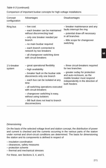
271
6
Table 6-3 (continued)
Comparison of important busbar concepts for high-voltage installations
Concept Advantages Disadvantagesconfiguration
Ring bus
1¹⁄₂-breakersystem
– breaker maintenance and anyfaults interrupt the ring
– potential draw-off necessaryin all branches
– little scope for changeoverswitching
– three circuit-breakers requiredfor two branches
– greater outlay for protectionand auto-reclosure, as themiddle breaker must respondindependently in the direction ofboth feeders
Dimensioning
On the basis of the selected voltage level and station concept, the distribution of powerand current is checked and the currents occurring in the various parts of the stationunder normal and short-circuit conditions are determined. The basis for dimensioningthe station and its components is defined in respect of
– insulation coordination– clearances, safety measures– protection scheme– thermal and mechanical stresses
For these, see Sections 3, 4, and 5.
– low cost
– each breaker can be maintainedwithout disconnecting load
– only one breaker needed perbranch
– no main busbar required
– each branch connected tonetwork by two breakers
– all changeover switching donewith circuit-breakers
– great operational flexibility
– high availability
– breaker fault on the busbar sidedisconnects only one branch
– each bus can be isolated at anytime
– all switching operations executedwith circuit-breakers
– changeover switching is easy,without using isolators
– BB fault does not lead to branchdisconnections
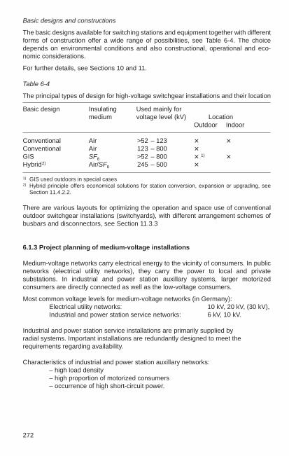
272
Basic designs and constructions
The basic designs available for switching stations and equipment together with differentforms of construction offer a wide range of possibilities, see Table 6-4. The choicedepends on environmental conditions and also constructional, operational and eco-nomic considerations.
For further details, see Sections 10 and 11.
Table 6-4
The principal types of design for high-voltage switchgear installations and their location
Basic design Insulating Used mainly formedium voltage level (kV) Location
Outdoor Indoor
Conventional Air >52 – 123 Conventional Air 123 – 800 GIS SF6 >52 – 800 1) Hybrid2) Air/SF6 245 – 500
1) GIS used outdoors in special cases2) Hybrid principle offers economical solutions for station conversion, expansion or upgrading, see
Section 11.4.2.2.
There are various layouts for optimizing the operation and space use of conventionaloutdoor switchgear installations (switchyards), with different arrangement schemes ofbusbars and disconnectors, see Section 11.3.3
6.1.3 Project planning of medium-voltage installations
Medium-voltage networks carry electrical energy to the vicinity of consumers. In publicnetworks (electrical utility networks), they carry the power to local and privatesubstations. In industrial and power station auxillary systems, larger motorizedconsumers are directly connected as well as the low-voltage consumers.
Most common voltage levels for medium-voltage networks (in Germany):Electrical utility networks: 10 kV, 20 kV, (30 kV),Industrial and power station service networks: 6 kV, 10 kV.
Industrial and power station service installations are primarily supplied by radial systems. Important installations are redundantly designed to meet therequirements regarding availability.
Characteristics of industrial and power station auxillary networks:– high load density– high proportion of motorized consumers– occurrence of high short-circuit power.

273
6
Planning medium voltage distribution networks
Distribution networks have, in general, developed historically and as a result arefrequently characterized by a high degree of meshing. The task of system planning isto design these networks to be simple and easy to comprehend.In planning electrical networks, a distinction is made between operational structuralplanning and basic strategic planning. Basic planning covers the following points:
– Supply principles,– Network concepts,– Standard equipment,– Standard installations.
The following forms of network are used with the corresponding switchgear installationconfigurations (DSS, ESS):
Ring network Network with oppositestation
Network with load-centre substation
Fig. 6-1:
Networks in which the individual transformer substations on the medium-voltage sideare not interconnected

274
Fig. 6-2:
Networks in which the individual transformer substations on the medium-voltage sideare interconnected
Corresponding transformersubstations
Corresponding transformersubstations with opposite station
A simple protection concept can be implemented in radial networks. Troubleshootingin the event of a fault is much easier, particularly with single-phase faults.
An important aspect of system planning is the neutral treatment. Public distributionsystems today are still mostly operated with earth fault compensation, with no trippingin the event of an earth fault. The low-resistance neutral earthing is available forselective breaking of single-phase faults. However, a new trend is to operate thenetworks with compensation and also to install short-time low-resistance neutralearthing (Kurzzeitige NiederOhmige SternPunktErdung, KNOSPE). The advantage ofKNOSPE is its selective interception of earth faults without interruptions of powersupply. The networks must be operated primarily as radial systems. Short-circuitindicators must be installed in the substations to allow selective fault location.
Planning medium-voltage switchgear
The standard structure of medium-voltage switchgear today is the factory-assembledtype-tested switchgear installation conforming to DIN EN 60298 (VDE 0670 Part 6).The most common structural types are described in Section 8.2.
The most important distinguishing characteristics of the currently available structuraltypes and the associated decision-making criteria are:

275
6
Distinguishing characteristics Technical decision-making criteria
Low costs Higher costs ––
Single Double Network conceptbusbars busbars
Air-insulated Gas-insulated Dimensions of the installationenvironmental conditions(contamination, moisture, servicerequirements, cleaning)
Cubile Metal- Personnel safety during wiring workclad Restriction of damage in the event of
internal arcing (if compartmentalization is designed for this)
Switch disconnector Circuit-breaker Rating datainstallation type installation type – Short-circuit currents
– Operating currents– Switching frequencyProtection concept
6.1.4 Planning of low-voltage installations
Low-voltage installations are usually near the consumer and generally accessible, sothey can be particularly dangerous if not installed properly.
The choice of network configuration and related safety measures is of crucialimportance. The availability of electricity is equally dependent on these considerations.
Table 6-5 compares the advantages and disadvantages of commonly used networkconfigurations, see also Section 5.1.
Another important step in the planning of low-voltage switchgear installations consistsof drawing up a power balance for each distribution point. Here, one needs to considerthe following:
– nominal power requirement of consumers,– short-time power requirement (e.g. motor startup),– load variations.
The IEC recommendations and DIN VDE standards give no guidance on these factorsand point out the individual aspects of each installation.
For power plants and industrial installations, the circumstances must be investigatedseparately in each case.
The following Tables 6-5 and 6-6 are intended as a planner’s guide. The planners canuse the information in Table 6-6 for reference.The total power is derived from the sumof the installed individual power consumers multiplied by the requirement factor with theformula:
Pmax = Σ Pi · g Pmax = power requirementPi = installed individual power producerg = requirement factor

276 Table 6-5
Summary of network configurations and protection measures for low-voltage installations
System1) Advantages Disadvantages Main application
TN system Fast disconnection of fault or High cost of wiring and cable Power plants, public powershort circuit. Least danger for due to protective conductors. supply and networks.people and property. Any fault interrupts operations.
TT system Less wiring and cable required. Complex operational earthing Livestock farming.Zones with different touch (≤ 2 Ω). Equipotential bondingvoltages permitted. Can be necessary for each building.combined with TN networks.
IT system Less expensive in respect of Equipment must be insulated Hospitalswiring and cables. throughout for the voltage bet- Industry.Higher availability: ween the outside conductors.1st fault is only signalled, Equipotential bonding necessary.2nd fault is disconnected.
Total insulation Maximum safety. Equipment doubly insulated, Residential, small-scaleCan be combined with other economical only for small consumers. switchboards and equipmentnetworks. With heat-generating loads,
insulation constitutes fire hazard.
Safety extra-low voltage No dangerous touch voltages. Limited power with cost-effective Small apparatus.Functional extra-low voltage equipment use. Special
requirements for circuitry.
1)For definitions and block diagram of the systems, see Section 5.1.2

277
6
Table 6-6
Demand factor g for main infeed of different electrical installations
Type of installation Demand factor g for Remarksor building main infeed
Residential buildingsHouses 0.4 Apply g to average use per
dwelling.Blocks of flats Total demand = heating + a.c.– general demand (excl. elec. heating) 0.6 typical + general.– electric heating and air-conditioning 0.8 to 1.0
Public buildingsHotels, etc 0.6 to 0.8 Power demand stronglySmall offices 0.5 to 0.7 influenced by climate, e.g.Large offices (banks, insurance – in tropics high demand forcompanies, public administration) 0.7 to 0.8 air-conditioningShops 0.5 to 0.7 – in arctic high heating de-Department stores 0.7 to 0.9 mandSchools, etc. 0.6 to 0.7Hospitals 0.5 to 0.75Places of assembly (stadiums,theatres, restaurants, churches) 0.6 to 0.8Railway stations, airports, etc. no general figure Power demand strongly
influenced by facilitiesMechanical engineeringMetalworking 0.25 Elec. drives often generouslyCar manufacture 0.25 sized.
Pulp and paper mills 0.5 to 0.7 g depends very much onstandby drives.
Textile industrySpinning mills 0.75Weaving mills, finishing 0.6 to 0.7
Miscellaneous IndustriesTimber industry 0.6 to 0.7Rubber industry 0.6 to 0.7Leather industry 0.6 to 0.7
Chemical Industry0.5 to 0.7
Infeed must be generouslyPetroleum Industry sized owing to sensitivity of
chemical production processesto power failures.
Cement works 0.8 to 0.9 Output about 3500 t/day with500 motors. (Large mills withh.v. motor drives.)
Food Industry 0.7 to 0.9Silos 0.8 to 0.9
MiningHard coalUnderground working 1Processing 0.8 to 1Brown coalGeneral 0.7Underground working 0.8
(continued)
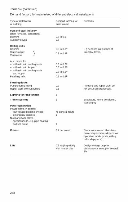
278
Table 6-6 (continued)
Demand factor g for main infeed of different electrical installations
Type of installation Demand factor g for Remarksor building main infeed
Iron and steel industry(blast furnaces, convertors)Blowers 0.8 to 0.9Auxiliary drives 0.5
Rolling millsGeneral 0.5 to 0.81) 1) g depends on number ofWater supply 0.8 to 0.91) standby drives.Ventilation
Aux. drives for– mill train with cooling table 0.5 to 0.71)
– mill train with looper 0.6 to 0.81)
– mill train with cooling table 0.3 to 0.51)
and looperFinishing mills 0.2 to 0.61)
Floating docksPumps during lifting 0.9 Pumping and repair work doRepair work without pumps 0.5 not occur simultaneously.
Lighting for road tunnels 1
Traffic systems 1 Escalators, tunnel ventilation,traffic lights
Power generationPower plants in general– low-voltage station services no general figure– emergency supplies 1Nuclear power plants– special needs, e.g. pipe heating,
sodium circuit 1
Cranes 0.7 per crane Cranes operate on short-time:power requirements depend onoperation mode (ports, rolling mills, ship-yards) .
Lifts 0.5 varying widely Design voltage drop for with time of day simultaneous startup of several
lifts

279
6
The type of construction depends on the station’s importance and use (requiredavailability), local environmental conditions and electromechanical stresses.
Construction Main application
Type-tested draw-out Main switching stationsswitchgear Emergency power distribution
Motor control centres
Type-tested fixed-mounted Substationsswitchgear a.c./d.c. services for h.v.
stationsLoad centres
Cubicles or racks Light/power switchboardsLoad centres
Box design Local distribution,Miniature switchboards
The short-circuit currents must be calculated in terms of project planning activity, theequipment selected in accordance with thermal stresses and the power cable ratingsdefined. See also Sections 3.2, 7.1 and 13.2. Particularly important is the selectivity ofthe overload and short-circuit protection.
Selective protection means that a fault due to overloading or a short circuit is inter-rupted by the nearest located switchgear apparatus. Only then can the intact part of thesystem continue to operate. This is done by suitably grading the current/timecharacteristics of the protection devices, see also Sections 7.1.4,14.3 and 15.4. Thechoice of relays can be difficult if account has to be taken of operating conditions withpowerful mains infeeds and comparatively weak standby power sources. In somecases changeover secondary protective devices have to be provided.
6.1.5 Calculation of short-circuit currents, computer-aided
A knowledge of the expected short-circuit currents in an installation is essential to thecorrect selection of the switching stations and the line-side connected networks. Themethods of calculation are described in chapter 3.
The upper limit value of these fault currents determines: – power ratings of the circuit-breaker, – mechanical design of the installation,– thermal design of the equipment, – electrical design and configuration of earthing systems, – maximum permissible interference in telecommunications systems.
The lower limit value of these fault currents determines: – protective relays and their settings.
The calculation of short-circuit currents therefore helps to solve the following problems:– dimensioning of equipment on the basis of (dynamic) stresses on closing and
opening and also the thermal stress,– designing the network protection system,– questions of compensation and earthing, – interference problems (e.g. in relation to telecommunications lines).
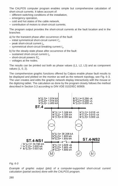
280
The CALPOS computer program enables simple but comprehensive calculation ofshort-circuit currents. It takes account of:– different switching conditions of the installation, – emergency operation,– cold and hot states of the cable network,– contribution of motors to short-circuit currents.
The program output provides the short-circuit currents at the fault location and in thebranches
a) for the transient phase after occurrence of the fault: – initial symmetrical short-circuit current I"k,– peak short-circuit current ip,– symmetrical short-circuit breaking current Ia.
b) for the steady-state phase after occurrence of the fault: – sustained short-circuit current Ik,– short-circuit powers S"k, – voltages at the nodes.
The results can be printed out both as phase values (L1, L2, L3) and as componentvalues (1, 0, 2).
The comprehensive graphic functions offered by Calpos enable phase fault results tobe displayed and plotted on the monitor as well as the network topology, see Fig. 6-3.The user creates and edits the graphic network display interactively with the mouse orthe digitizing tablet. The calculation as done by the program closely follows the methoddescribed in Section 3.3 according to DIN VDE 0102/IEC 60909.
Fig. 6-3
Example of graphic output (plot) of a computer-supported short-circuit currentcalculation (partial section) done with the CALPOS program.

281
6
6.1.6 Calculation of cable cross-sections, computer-aided
Before the cross-sections of cables between the switchgear and their connected loadsare finalized, they must be calculated in relation to the operating conditions and cablelength.
Factors influencing the cross-section in this calculation are:
– permitted loadings under normal conditions, taking into account ambienttemperatures and methods of laying,
– thermal short-circuit strength,
– permitted voltage drop along the cable run under normal conditions, and also duringthe starting phase when feeding motors,
– response of protective devices in the event of overloads and the smallest possibleshort-circuit current to interrupt dangerous touch voltages.
The ABB-developed LEIOP computer program and the matching Calpos modulemakes it possible to carry out this comprehensive calculation for every current circuit.By entering the circuit data, such as operating current, max. and min. short-circuitcurrent, tripping currents/times of the protective devices and maximum permittedvoltage drops, the program selects the appropriate minimum cross-section for theconsidered cable length. With the aid of program parameters, the range of cable typesto be used can be limited, and a choice provided of the number of parallel cables for a given cable cross section. The method of calculation is in accordance withDIN VDE 0100, VDE 0276 and the respective cable manufacturer’s data.
6.1.7 Planning of cable routing, computer-aided
The routing of cables in complex industrial installations, power plants and switchingstations requires a great deal of work on the part of the planner. It involves arrangingthe cables to give the shortest path between their starting point and destination, whileat the same time ensuring that certain combinations do not adversely influence eachother.
The ABB program LEIOP offers very effective support here. It can provide data on thefollowing:
– Cable lists – Cable quantities incl. fittings (number of terminal ends, individual cable lengths) – Cable markings – Information on cable installation – Information on tailoring cables for racks, trenches and conduit

282
6.2 Reference designations and preparation of documents
Two important series of standards in the last few years have guided the rules for thereference designation of equipment and the preparation of circuit documents. Thesymbols for individual equipments are specified in the series DIN 40900, and the seriesDIN 40719 regulates reference designation and representation.
The two series of standards have been or are being superseded due to internationalstandardization in the IEC. DIN 40900 has been replaced by the series DIN EN 60617.The changes are minor, because DIN 40900 was already based on an earlier versionof the international standard IEC 60617. The new revision corrects errors and includesessential supplementary symbols. The most important parts of DIN 40719 weresuperseded by DIN EN 61082 in 1996/97. Part 2 of DIN 40719, which covers theidentification of electrical equipment, and Part 6, covering the area of function charts,are still applicable for Germany. The structure of reference designation systematics hasbeen fundamentally revised on an international level. With the publication of DIN EN61346-1, the first part – the basic rules – has already appeared. Part 2 with theimportant tables of code letters is currently in preparation. DIN 40719 Part 2 will remainin force until the German version is published. In the following section, the currentdesignation systematics practice is reproduced virtually unchanged from the 9thedition, because this system is still used for extensions and for running projects.Section 6.2.4 gives an overview of future developments in reference designationsystematics, in accordance with the new international standard IEC 61346.
6.2.1 Item designation of electrical equipment as per DIN 40719 Part 2
Four designation blocks are available to identify every single device (equipment) in theplant and in the circuit diagrams. They are distinguished by prefix signs.
Prefix signs Designation block
= Higher level designation+ Location of item– Type, number, function of the item: Terminal designation
Each designation block consists of a sequence of alphanumeric characters. It is dividedinto sections and each section into data positions. These signify:A – an alphabetic data position (letter),N – a numerical data position (digit).
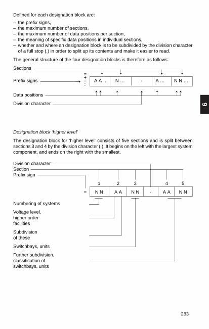
283
6
Defined for each designation block are:
– the prefix signs,– the maximum number of sections,– the maximum number of data positions per section,– the meaning of specific data positions in individual sections,– whether and where an designation block is to be subdivided by the division character
of a full stop (.) in order to split up its contents and make it easier to read.
The general structure of the four designation blocks is therefore as follows:
Sections=+
Prefix signs – A A … N … · A … N N …:
Data positions
Division character
Designation block ‘higher level’
The designation block for ‘higher level’ consists of five sections and is split betweensections 3 and 4 by the division character (.). It begins on the left with the largest systemcomponent, and ends on the right with the smallest.
Division characterSectionPrefix sign
1 2 3 4 5
= N N A A N N · A A N N
Numbering of systems
Voltage level,higher order facilities
Subdivision of these
Switchbays, units
Further subdivision,classification of switchbays, units
→ → → →
→ →→ → →→→
→

284
The meanings of the alphabetical data positions in section 2 are defined in the standardand can be seen in Tables 6-7 and 6-8.
Table 6-7
Letters for identifying voltage level in the designation block ‘higher level assignment’,2nd section, 1st alphabetical data position (as Table C7 of DIN 40 719 Part 2).
Sections 1 2 3 4 5
Data positions = N A A N N · A A N N
Prefix sign
Identifying Systemletter
A –B > 420 kVC 380 kV to 420 kVD 220 kV to < 380 kVE 110 kV to < 220 kVF 60 kV to < 110 kVG 45 kV to < 60 kVH 30 kV to < 45 kVJ 20 kV to < 30 kVK 10 kV to < 20 kVL 6 kV to < 10 kVM 1 kV to < 6 kVN < 1 kVP –
Q Facilities for measuring and meteringR Facilities for protectionS –T Facilities for transformersU Facilities for control, signalling and
auxiliary equipmentV –W Facilities for control roomsX Central facilities, e g process computers,
alarm systemsY Facilities for telecommunications
Z –
Note: The letters A to N for voltage level are the same as in Table 6-9, but there they are used for a different identification purpose.
→
Facilities and systemsnot specifically referringto a branch or voltage

285
6
Table 6-8
Letters for identifying voltage levels < 1 kV in designation block ‘higher levelassignments’, 2nd section, 2nd alphabetical data position when the letter N is definedfor the first alphabetical data position in Table 6-7 (as Table C9 of DIN 40719 Part 2)
Sections 1 2 3 4 5
Data positions = N A A N N · A A N N
Prefix sign
Identifying Meaningletter
N Systems < 1 kVNA AC 500 to 1000 VNB AC 500 to 1000 VNC AC 500 to 1000 VND –NE AC 400/230 VNF AC 400/230 VNG AC 400/230 VNH AC 400/230 VNJ –NK DC 220/110 VNL DC 220/110 VNM DC 220/110 VNN DC 220/110 VNP –NQ DC 60/48 VNR DC 60/48 VNS DC 60/48 VNT –NU DC 24/12 VNV DC 24/12 VNW DC 24/12 VNX –NY –NZ –
→ →
Designation block ‘location’
The ‘location’ designation block is qualified by a plus sign (+) and indicates where anitem of equipment is situated, e.g. topographical site: building, room, cubicle, rack andposition.The designation block is divided into six sections:
+ N N A A N N A A N N · A A … N N
1 2 3 4 5 6Prefix signSectionDivision character

286
Table 6-9
Letters for identifying locations in designation block ‘location’, 4th section, 1st alpha-betical data position (as Table C10 of DIN 40719 Part 2)
Sections 1 2 3 4 5 6
Data positions + N N A A N N A A N N · A A … N N
Prefix sign
Identifying Meaningletter
A –B > 420 kVC 380 to 420 kVD 220 to < 380 kVE 110 to < 220 kVF 60 to < 110 kVG 45 to < 60 kVH 30 to < 45 kVJ 20 to < 30 kVK 10 to < 20 kVL 6 to < 10 kVM 1 to < 6 kVN < 1 kV baysP DesksQ Boards and cubicles for measuring and meteringR Boards and cubicles for protective devicesS Boards and cubicles decentralizedT Boards and cubicles for transformersU Boards and cubicles for control, signalling and auxiliary systemsV Marshalling cubiclesW Control room boardX Boards and cubicles for central facilities, e. g. alarm systems and
process computersY Boards and cubicles for telecommunicationsZ –
Application: The letters A to N for voltage level are the same as in Table 6-7, but there they are usedfor a different identificatiaon purpose.
The designation block begins on the left with the unit of largest volume or construction,and ends on the right with the smallest.The designation block can be subdivided by the division charakter (·) between sections5 and 6.To the left of the division character is information on the location (building, room, row,etc.) and the nature of the structural unit (bay, cubicle, rack).To the right of the division character in section 6 is information on the position (row,column, etc.) of an item of equipment within the structural unit. Section 6 may have upto eight data positions (letters and numbers in any sequence).The meanings of the alphabetical data positions in section 4 are shown in Tables 6-9
→

287
6
Table 6-10
Letters for identifying application in designation block ‘location’, 4th section, 2ndalphabetical data position (as Table C11 of DIN 40719, Part 2)
Sections 1 2 3 4 5 6
Data positions + N N A A N N A A N N · A A … N N
Prefix sign
Identifying Meaningletter
A Circuit-breaker accessoriesB Multiply, re-position, decoupleC Instrument transformer accessoriesD Compressed air, hydraulicsE –F –G –H –J Automatic, closed-loop controlK –L Simulating network, voltage selectionM MeasurementN System servicesP RecorderQ MeteringR ProtectionS SynchronizingT TransformersU AuxiliariesV Main, secondary busbars etc.W Display, operation, supervisionX Alarm systemY –Z –
→

288
Designation block ‘identification of item’
The designation block for ‘identification of item’ is qualified by a hyphen (–) and consistsof three sections.Specified for the data positions in this designation block are the following symbols(letters and numbers) in the order given.
Sections
Prefix sign 1 2 3
N– A N N N A
A
Kind
Number
Function
Section 1 identifies the kind of item as in Table 6-11.
Section 2 states the number of the equipment. Each item of equipment must beidentified by a number of one to three digits.
Items of different kinds that belong together should be given the same number.
DIN 40719 Part 2 gives rules for the numbering of items in high-voltage switchgearinstallations, a distinction being made between numbers for
– switchgear in the main circuits (Table 6-12a) – auxiliary devices which can be assigned to the switchgear in the main circuits
(Table 6-12b)– current and voltage transformers in the main circuits (Table 6-13) – equipment which is specific to a branch but cannot be assigned to the main
switchgear (Table 6-14).
If necessary, the function of an item of equipment can be identified in section 3. Thefollowing letters are specified for the alphabetical data position:A – OFF function E – ON function L – conductor identification
The other letters can be chosen arbitrarily.
The second data position for further subdivision/numbering can be occupied by anadditional, arbitrarily chosen letter or number.
In the case of conductor identification, a distinction is made between a neutral identityLA, LB, LC and an identity assignable to the conductors L1, L2, L3. If neutral conductoridentification is used, its assignment to L1, L2 and L3 must be stated in the circuitdocumentation.

289
6
Table 6- 11
Letters for identifying the kind of item (as Table 1 of DIN 40719 Part 2)
1 2 3
N– A N N N A
A
Letter code Kind of item
A Assemblies, subassembliesB Conversion from non-electrical to electrical quantities and vice versaC CapacitorsD Binary elements, delay devices, storage devicesE MiscellaneousF Protection devicesG Generators, power supply systemsH Signalling systemsJ –K Relays, contactorsL Inductors, reactorsM MotorsN Analogue elements as amplifiers, controllersP Measuring instruments, testing devicesQ Switching devices for power circuitsR ResistorsS Switching devices for control circuits, selectorsT TransformersU Modulators, converters from one electrical quantity to anotherV Tubes, semiconductorsW Transmission paths, cables, busbars, hollow conductors, antennasX Terminals, plugs, socketsY Electrically operated mechanical devicesZ Terminations, bifurcations, filters, equalizers, limiters,
balancing devices, bifurcation terminations

290
Designation Control- Control buttonKind of item discrepancy
switch open closed
Circuit-breakersGeneral Q10 S10 S10A S10E1st circuit-breaker Q01 S01 S01A S01E2nd circuit-breaker Q02 S02 S02A S02EBus system IBus disconnector Q11 S11 S11A S11EBus-coupler disconnector,2nd disconnector Q10 S10 S10A S10EBus sectionalizer Q11…14 S11…14 S11…14 S11E…14EBus-earthing switch Q15…19 S15…19 S15A…19A S15E…19EMaintenance earthing sw.General Q15 S15 S15A S15E1st maint. earthing sw. Q51 S51 S51A S51E2nd maint. earthing sw. Q52 S52 S52A S52EFreely available Q16 S16 S16A S16Eneutral earthing switch,test disconnectorBypass busDisconnector Q17 S17 S17A S17E2nd disconnector Q70 S70 S70A S70ESectionalizer Q71…74 S71…74 S71A…74A S71E…74EEarthing switch Q75…79 S75…79 S75A…79A S75E…79EEarthing switchesGeneral Q18 S18 S18A S18E1st earthing switch Q81 S81 S81A S81E2nd earthing switch Q82 S82 S82A S82EFeeder disconnectorGeneral Q19 S19 S19A S19E1st feeder disconnector Q91 S91 S91A S91E2nd feeder disconnector Q92 S92 S92A S92E
Table 6-12b (taken from Table C4 of DIN40 719 Part 2). Number for the designationof auxiliary devices that can be associatedwith the switchgear as in Table 6-12a inthe title block “Type, number, function”,2nd section, 1st and 2nd numeric dataposition.
Table 6-12a (taken from Table C3 ofDIN 40719 Part 2). Number for thedesignation of switchgear in the maincurrent circuit in the title block “Type,number, function”, 2nd section, 1st and2nd numeric data position.
Table 6-12
Designation block ‘identification of item’
1 2 3
N– A N N N A
A
1 2 3
N– A N N N A
N
If in the 1st section, the letter “Q” as inTable 6-11 is used for switchgear in themain circuit.

291
6
Instrument transformersKind of item Designation Kind of item Designation
Current transformers Voltage transformersFeeder transformers T 1 to 4 Feeder transformers T 5 to 9Transformer bus I T11 to 14 Transformer bus I T15 to 19Transformer bus II T21 to 24 Transformer bus ll T25 to 29Transformer bus III T31 to 34 Transformer bus lll T35 to 39Transformer bus IV T41 to 44 Transformer bus IV T45 to 49
Cable-type transformersGeneral T901st transformer T912nd transformer T92
Table 6-14
Number for identifying purpose of non-assignable feeder-related auxiliaries indesignation block ‘identification’, 2nd section, 1st, 2nd and 3rd numerical data position(as Table C6 of DIN 40719 Part 2)
Table 6-13
Number for identifying the application in designation block ‘identification’, 2nd section,1st and 2nd numerical data position (as Table C5 of DIN 40 719 Part 2) if the letter “T”as in Table 5 is used in the section for instrument transformers in the main circuits.
1 2 3
N– A N N N A
A
T ↑ ↑
1 2 3
N– A N N N A
A
↑ ↑ ↑
Identifying letter as Table 6-11, three-digit number
Recommended categories for the three-digit number:
100 to 199 Station services200 to 299 Control300 to 399 Protection400 to 499 Measurementfrom 500 arbitrary use
The number of auxiliaries in higher-order facilities and within branch-relatedcombinations can be chosen at will.

292
Composite items
To identify an item of equipment forming part of higher level equipment (compositeitem), the identifying designation blocks are arranged in sequence with the higher levelequipment at the left. In the case of composite items, each item is given its own identityand the prefix sign of a hyphen (–) is repeated for each item, e.g. –QO-Y1 for acircuit-breaker –QO containing a tripping coil –Y1.
The numbers for equipment forming part of higher level equipment can be chosenarbitrarily, e.g. equipment in disconnector operating mechanisms, circuit-breakers,combinations, truck-mounted assemblies.
Designation block ‘terminal’
The ‘terminal’ designation block has the prefix sign of a colon (:) and consists of onesection.
Section
Prefix sign
: A A … N N
The designation block contains the terminal identifications as stated on the equipment.

293
6
6.2.2 Preparation of documents
As per DIN EN 61082, “document” is defined as “information on a data medium”;“documentation” as:
– collection of documents related to a given subject, and– processing of documents.
The “standard” classification for documents in electrical engineering as per DIN 40719distinguishes between a) purpose and b) type of representation. The most importantparts of DIN 40719 were superseded by DIN EN 61082 in 1996. This standard is adirect translation of the international standard IEC 61082 “Preparation of documentsused in electrotechnology”. Document classification is also covered here – includingnew terms in some cases. The following definitions of the new standard can beassigned to the term “purpose” in the old standard without problems:
– Function oriented documents – Commissioning-specific documents– Location documents – Operation-specific documents– Connection documents – Maintenance-specific documents– Item lists – Reliability and maintainability-specific documents– Installation-specific documents– Other documents
Regarding the “type of representation”, the new standard distinguishes the followingtypes:
– Attached representation – Grouped representation– Semi-attached representation – Dispersed representation– Detached representation – Multi-line representation– Repeated representation – Single-line representation
A distinction is also made between a “functional oriented layout” and a “topographicaloriented layout” in the types of representations for circuit diagrams.
An important change from the former practice as per DIN 40719 is the strict separationof title block data and information on the reference designation (formerly equipmentidentification). Common designation blocks for represented equipment may no longerbe given in the title block. Only data relevant to the document itself is given here now.Higher-order parts of the reference designation must be given at the specified positionsin the drawing field (e.g. top left of the circuit diagram).
The following definitions from DIN 61082 / IEC 61082 and descriptions are given forsome documents – important for substation engineering.
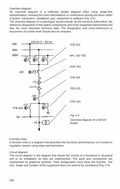
294
Overview diagramAn overview diagram is a relatively simple diagram often using single-linerepresentation, showing the main interrelations or connections among the items withina system, subsystem, installation, part, equipment or software (Fig. 6-4).The overview diagram of a switchgear should include, as the minimum information, thereference designation of the station components and of the equipment represented andalso the most important technical data. The designation and cross-references todocuments of a lower level should also be included.
TFB 420
HPL 420 TB2
AOK 420
TFB 420
TEB 420
CPB 420
Fig. 6-4
Overview diagram of a 420 kVfeeder.
Function chartA function chart is a diagram that describes the functions and behaviour of a control orregulation system using steps and transitions.
Circuit diagramThe circuit diagram is the diagram that shows the circuits of a functional or structuralunit or an installation as they are implemented. The parts and connections arerepresented by graphical symbols. Their configuration must show the function. Thesize, shape and location of the equipment does not need to be considered (Fig. 6-5).
BBI
BBII
BBIII
420 kV 3 ~ 50 Hz
–Q1 –Q2 –Q3
–Q0
K–T1
L1-L3
–Q9L
TB
TFB 420–Q8
–T5
–Q7

295
6
Fig. 6-5
Circuit diagram
Q0_ORD_OPEN_P9109.CR02
-S0
-K0A
-K0E -K206 -Y3
-K0E
Q0_ORD_CLOSE_N9112.CR01
-K0E -S0
-K206
-K0A-K0E
-K0E
-Y1
Q0_ORD_CLOSE_P9109.CR01
-Y2
-S1
Q0_ORD_OPEN_N9112.CR02
-K203
-S0
-K0A
A
B
C
D
E
A
B
C
D
E
.1 .2 .3 .4 .5 .6 .7 .8
.1 .2 .3 .4 .5 .6 .7 .8
HOCHSPANNUNGSANLAGE
=E05
+SR
STEUERSCHRANK
+SR
STEUERSCHRANK
-F200
MOTOR
AUS BEFEHL EIN BEFEHL SCHLIESSEN EIN SPULE AUS1 SPULE AUS2 SPULEAUS2 BLOCKIERUNGLEISTUNGSSCHALTER PRUEFKLEMMEN EIN/AUS-Q0
-A112
-A109
10L+
10L-
14L+
14L-
(10L+)
(14L+)
(10L+)
circuit-breaker –Q0
Control cubicle
High-voltageswitchyard
Control cubicle
OFF command ON command Close coil ON OFF 1 Coil OFF 2 blocking OFF 2 coil Test terminals ON/OFF
296
The circuit diagram for a feeder or a functional unit is generally subdivided into functiongroups, such as control, position indication, interlocking, alarm, synchronization,protection, measuring etc. Above the current path, a short description of therepresented subfunction using keywords is useful. The most important part of the circuitdiagram is the information on following circuits or signals and notes on furtherrepresentations.
Terminal function diagramA circuit diagram for a functional unit, which shows the terminals for the interfaceconnection and describes the internal functions. The internal functions may be shownor described in simplified form.
Arrangement drawingA drawing showing the location and/or the physical implementation of a group ofassociated or assembled parts.
Terminal connection diagramA diagram that shows the terminals of a construtional unit and the internal and/or external connections.
6.2.3 Classification and designation of documents
The international standard IEC 61355 has the title “Classification and designation ofdocuments for plants, systems and equipment”. The goal of this standard is describedas follows in its introduction:
One aim of this standard is to establish a method for better communicationand understanding between parties involved in document interchange. Inorder to get a basis for a system, it is necessary to disregard, more or less,what a document is called today. Different names are in use for the samedocument kind or the names may have different meanings for different parties.The purpose and object of interest are sometimes also part of document titles,which hampers general understanding. Therefore the basis for a commonunderstanding should be a classification scheme which is based only on thecontent of information.
Another aim of this standard is to set up rules for relating documents to theobjects they describe. For this purpose a document designation system isprovided, linking the document kind designation to the object designationused within the plant, system or equipment. Following the rules andrecommendations given, the documentation reflects the structure of the “realinstallation”. By that also guidance is given for order and filing as well as forstructured searching for information, for example in document retrievalsystems.

297
6
The principle of classification also covers the needs of computer-baseddocumentation in general. An increasing amount of information will be storedand interchanged in a standardized data base format. The information to bedelivered may be specified in such a way that each document kind requiredand agreed tby parties can be derived from that data base by the receiver’scomputer system.
This standard specifies a generally valid “Document kind Classification Code (DCC)”for the first time and explains it in a detailed table with examples – see the fields withgrey background in the following table. Documents are identified in accordance with the following scheme:
The letter symbol “A1” stands for the Technical Area, e.g. “E” for electrotechnology; theletter symbol “A2” stands for the “Main Document Kind Class”, e.g. “F” for function-describing documents; the letter symbol “A3” stands for the “Document Type Subclass”,e.g. “S” for circuit diagram.Object designation follows the rules of IEC 61346, and currently still DIN 40719-2. Thepage number after the prefix sign “/” has a maximum of six data spaces and can beformed by the customary procedure (e.g. “D” for power supply AC, or “N” for protection).Table 6-15 shows examples of document kind classes from switchgear installationtechnology.
→
→
→
→
→
=+–
A ....... N & A1 A2 A3 N N N / A ........ N
Object designation
Prefix signIdentifying letters and numbers
Prefix signCounting numbers of sheets

298
Table 6-15Examples for documents in switchgear installations
Letter symbol2nd & 3rd A position Document kind; examples from switchgear installationas per IEC 61355 technology
Documentation describing documents
AA Administrative documents: cover sheets, documentationstructure, designation system
AB Tables: lists of documents, lists of contents
Management documents
B. Document list, schedule, delivery list, training documentation,letters, memos
General technical documents
DA Dimension drawings, circuit diagrams for equipment
DC Operating and maintenance instructions
Technical requirements and dimensioning documents
E. Environmental conditions, studies, calculations
Function-describing documents
FA Overview diagrams, network maps
FB Flowcharts, block diagrams
FE Function descriptions
FF Function diagrams
FP Signal descriptions, signal lists
FS Circuit diagrams
FT Software-specific documents
Location documents
LD Site plan, cable routing drawings, earthing plans, layouts, dispositions, sections
LH Building plans
LU Assembly drawings, arrangement drawings, equipment layout ˇˇdiagrams
Connection-describing documents
MA Terminal diagrams, connection diagrams, interconnectiondiagram
MB Cable tables, cable lists
Documents listing material
PA Material lists (conduits, stranded wires, terminals, bolts ...)
PB Parts lists, spare parts lists, lable lists
Quality managment documents
QA Test reports, test certifications, audit reports

299
6
6.2.4 Structural principles and reference designation as per IEC 61346
As noted in the introduction to Section 6.2, this section gives an outlook on theexpected structural principles and reference designations in installations for energydistribution. The significance of this change from the former practice justifies this earlyexplanation.
Formerly designation in installations was done with designation blocks and tables witha fixed arrangement for particular, specified data positions within the designationblocks. However, in future, the hierarchical structure will be in the foreground and at thecentre. Hierarchical structures are characterized in that they build on “componentrelationships". The elements in a lower-order level in such a structure are always acomplete component of the next higher level. The structure formed in this way can bedepicted as a tree structure with nodes and branches (Fig. 6-6).
In its practical application for a switchgear installation, a structure will be implementedin accordance with the purpose under the following familiar classes: “association withvoltage level” and “function”. Every object considered in a hierarchical structure, infact the entire structure, the entire system itself can be considered from various pointsof view, referred to as “aspects”, e. g.:
– what it does;– how it is constructed;– where it is located.
With reference to these three types of aspect, the new designation systemdistinguishes system structures under the following three views:
– function-oriented structure;– product-oriented structure;– location-oriented structure.
Fig. 6-6Example of tree structureB, C and D are components of AE, F and G are components of B
The letters are for explanationonly; they have nothing to dowith any coding.

300
Reference designations derived from this are identified with the allocated prefix signs “=”, “–” and “+”. Note the following: the functional identification “=” is used only foridentifying pure functions, such as “= F” for “protection”; implementation with anyproduct is not considered at this stage! An example of an application would be a neutraldescription independant of manufacturer as a request in a specification. In actual usethis function might be implemented with, for example, the protection device “- F 312”.Consultations have shown that it makes sense for equipment in installations of energydistribution to be designated under a product-based structure. Designation in thelocation-oriented structure “+” remains open for straight topographical information,such as waypoints, floors, room numbers, etc. The difference from the previousequipment designation is primarily that there is no combination of the designationblocks “=”, “–” and “+”. An actuating element in a 380 kV control cubicle would for example be uniquelydescribed with the reference identification “– C3 – S1 – K1” in the product-orientedstructure.

301
6
6.3 CAD/CAE methods applied to switchgear engineering
The first CAD systems came on the market early in 1970. They were suitable for2-dimensional design work, e.g. drafting circuit diagrams, circuit board layouts andsimple design drawings. Now there is a wide variety of CAD workstations available,from low- to high-performance and all kinds of applications. Since 1970, CAD stationsand methods have evolved into a powerful tool. This development process can beexpected even to accelerate in coming years. The following section aims to explain themost important terms that have grown out of this new technology, and to give a generalpicture of the hardware and software systems employed. Attention is focused on theCAD methods used by ABB for switchgear engineering, together with examples.
6.3.1 Terminology, standards
Table 6-16 gives an outline of the principal CAD terms and their related fields ofapplication.
Table 6-16
CAD terms, summary and applications
CIM Computer-Integrated Manufacturing
CAE Computer-Aided Engineering
Typicalapplications
CAD Designdevelopment;
Computer-Aided Design PreparationComputer-Aided Drafting of drawings and
calculation
CAP Production planning
Computer-Aided Planning e.g. pricing anddeployment
CAM Production control
Computer-Aided Manufacturing e.g. parts lists,documentation forNC machines
CAT Computer-Aided Testing Control ofautomatic testing;test reports

302
Depending on the degree of standardization, the solutions stored in the computer andthe ability to help the designer find the right solution, CAD = Computer-Aided Draftingbecomes a complete design system. By further processing of CAD data formanufacturing documents, production planning and testing, you can create a CAM orCIM system. Fig. 6-7 gives a general overview of the CAD areas in relation of theengineering and manufacturing, showing the possibilities for standardization in thepreparation of circuit diagrams.
Fig. 6-7
Possibilities of standardization using CAD for producing circuit diagramshatching = CAD /CAE solutions1 Preparatlon by hand, 2 Manual preparation is replaced by advancing use of CAE
Table 6-17
Overview of the most important CAD standards
Standard Status Working title
DIN V 40719 -1000 04/93 Rules for computer-supported creation ofcircuit diagrams
DIN EN 61355 11/97 Classification and identification of documents forinstallations, systems and equipment
DIN EN 61082-1 bis-4 *) Documents of electrical engineering
DIN EN 61360-1, -2 und -4 *) Standard data element types with associatedclassification scheme for electrical components
DIN EN 81714 -2 09/99 Generating graphic symbols for application inthe documentation of products
DIN EN 60617-2 bis -13 *) Graphic symbols for circuit diagrams
*) See Table 6-24
(continued)

303
6
Table 6-17 (continued)
Overview of the most important CAD standards
Standard Status Working title
DKE 04/96 Standard symbol file for graphic symbols accordingstandard symbol file to DIN EN 60617 standards series based on DIN V
40900-100 and DIN V 40950
CAD-Lib Standard library with standard mechanical parts
VDA-PS FORTRAN interface for graphic design
IGES Initial graphics exchange standard, interface forexchange of CAD data, emphasis in geometry
EDIF Electronic data interface format for electricalengineering, emphasis on digital and analogueelements
DIN V 40950 08/92 Process-neutral interface for circuit-diagram data(VNS)Format for exchange of documentation ofelectrotechnical installations 2nd edition
ISO/IEC 10303 STEP Standard for the exchange of product-modeldata
In the last few years, the necessity of standards in the CAD area has been recognizedat both national and international level. Table 6-17 contains an overview of the mostimportant standards and drafts in the CAD area.
All interfaces are worked out at international level by the ISO (InternationalOrganization for Standardization) in TC 184 “STEP”, with application models for thevarious applications being processed in special working groups.

304
6.3.2 Outline of hardware and software for CAD systems
A CAD station consists of a computer with its immediate peripherals such as disk andcassettes, the dialogue peripherals and the CAD output devices. Tables 6-18 to 6-21show selection criteria and the capabilities of components for CAD systems. The CADworkstation today is a single working place with central data storage at a server in thenetwork.
Table 6-18
CAD computer system with directly connected peripherals (without plotter);
Main processor of the Application PeripheralCAD computer
Personal computer 2D/3D Magnetic diskwith graphics processors Floppy disk
CD drive
Workstation 2D/ 3D Magnetic diskwith graphics processors Cassette drive
Table 6-19 Input/output devices of CAD systems
Input device Output device Graphics Alpha-numeric
Digitizer × ×Plotter × ×Laser printer × × ×Passive graphics × ×terminalInteractive alphanumer. × × ×terminalInteractive graphics × × × ×workstation

305
6
Table 6- 20Alternative hardware components of an interactive graphics CAD terminal
Graphics display unit Coordinate positioning and input Command input, alphanumeric
– refresh rate > 75 Hz – electronic stylus with menu tablet – A/N keyboardmono/colour – mouse – predefined fields on menu15” to 19” diagonal – allocation of function keys1024 x 768 pixels – command menu display on screen, selection
mouse (windows method)
Table 6-21
The important graphics output devices
Plotter principle Format size Output, quality Plot production time
Electrostatic plotter, Height A4 to A0 Multicolour, quality 1 to 2 minutesdrawing resolved into dots Length up to 10 m very good
Ink-jet plotter, A4 to A0 Multicolour, filled-in areas, Up to 1 hr, depending on informationInk spray nozzle quality average volume
Microfilm plotter Up to A0 Film, quality very good Measured in seconds, up to 1 minuteto A1/A0
Laser printer/plotter A4 to A0 Multicolour, quality very good Seconds to minutes

306
The performance of CAD systems depends not solely on the hardware, but to a verylarge degree on the software. While the hardware generally determines the responsetime and processing speed, the software influences the methodology and how theapplications function.
The bottom rung in the software hierarchy is the operating system level, which isusually provided by the hardware supplier. The CAD software constitutes the usersoftware and is the second level in the software hierarchy. This user software is usuallydivided into a general CAD-oriented part and a problem-oriented part which takes intoaccount the particular criteria and boundary conditions of the engineering task in hand.A CAD system for switchgear engineering thus includes problem-oriented usersoftware for tasks such as
– station layout and planning,– planning of buildings,– preparation of circuit diagrams,– cable systems,– mechanical design
The computer is able to generate either 2D or 3D models.
Here,2D means representation in one plane.
3D means true working in three dimensions, showing views from different angles andperspectives. A distinction is made between edge or wire models, surface and volumemodels.
The objectives of introducing CAD methods are as follows:
– Improved quality of engineering solutions and drawing documentation,– Time savings on individual steps and entire project,– Flexible handling of modifications,– Technically safe, common standard variants and repeating solutions,– Comprehensive use of EDP by linking CAD, CAM, CAP and CAT.
In any overall assessment of new CAD methods or systems, these advantages must beset against the preparatory work and requirements in each individual case:
– Analysis of present situation and structuring of tasks, – Investment for hardware and software, – Establishment of symbol and drawing library and databases, – Training of engineering staff, – Initial acceptance.

307
6
6.3.3 Overview of CAD applications in ABB switchgear engineering
ABB switchgear engineering has been using CAD methods for many years and on anever increasing scale for planning tender and order processing. The CAD systems aresubject to a continuous process of development to meet the continuing progress in thearea of switchgears and the increasing use of digital station control systems.
Integration of the various CAD systems into an object-oriented environment is anessential requirement for optimizing the entire planning process. This extends fromprocessing tenders to processing orders for commissioning and further to service. Soalso the documentation of the installation and archiving is included.
The CAD systems in use are based on CAD operating software, which can nowgenerally run on different hardware platforms with different operating systems. Inaddition, problem-oriented application programs, mostly ABB-internal, have beendeveloped to run with them. They are designed to meet the requirements of users andcustomers. The quality assurance of the process is shown in Fig. 6-8.
A number of CAD systems with varying internal system logic are available on theGerman market in the area of electrical engineering. A decisive point in selecting a CADsystem, in addition to the straight hardware and software costs, is the expense of thetraining required and of establishing internal company databases for symbols andcomponents. Other important criteria are the functionality of the CAD system, theoptions for connecting to the internal company processes and the supported interfaces.
Fig. 6-8
Quality features of theCAD/CAE process.Quality loop with theengineering organizationcontrol functions,repeating solution, dataprocessing testing andoutput technology.
standardized diagramsstandardized equipmentcomponent symbolsdatabasestored solution know-how
programming systemrepeating solutionssecured know-how
quality controlby CAD / CAE
microimage plotterelectrostatic plotterlaser printerlong-term archiveon CD
the four stagesof engineering
organizationalintegrationspecification of data interfacesinput check
output quality
DP testcompleteplausibilitycompatibility
specifiedquality
actualquality
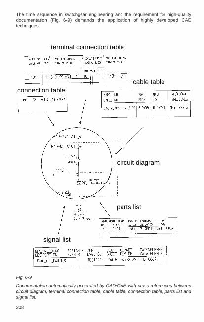
308
Fig. 6-9
Documentation automatically generated by CAD/CAE with cross references betweencircuit diagram, terminal connection table, cable table, connection table, parts list andsignal list.
The time sequence in switchgear engineering and the requirement for high-qualitydocumentation (Fig. 6-9) demands the application of highly developed CAEtechniques.
terminal connection table
cable tableconnection table
circuit diagram
parts list
signal list

309
6
Interfaces for high-end data exchange are becoming increasingly important forCAD/CAE technologies. More and more customers today are demanding theirdocumentation on electronic media. Particularly in Germany, the CAD system withwhich the documentation must be generated is frequently specified. For switchgearengineering, this is a significant restriction and above all, extremely cost-intensive.Today in particular, no company can afford to run several CAD systems internally inparallel for one application. The cost of hardware, software, administration andemployment of trained staff for several systems is simply too high.
However, even within ABB, data must be forwarded to subcontractors and processed.This leaves only the subject of interfaces (and those high-end) as the only alternativefor an efficient data exchange.
The standard IGES and DXF interfaces are suitable only for simple graphic dataexchange. Higher-end interfaces such as VNS (process-neutral interface for circuitdiagram data as per DIN V 40950 2nd edition) offer options for exchanging graphic andlogical information between electrical CAD systems at a significantly higher level. Adata exchange process that covers nearly everything has been developed with STEP(STandard for the Exchange of Product model data as per ISO/IEC 10303). However,this also requires a general rethink among the software suppliers, because dataexchange using STEP also requires STEP-conforming tools with object-orienteddatabases as a starting point. The first CAD suppliers have already started on this path.The interface properties defined as the application model for the various applicationshave already been published for mechanical engineering (AP 214) as a standard, andare in the process of being internationally approved for electrical engineering (AP 212).
Suitable CAD/CAE tools are also available for CAD and computer-supportedprocessing of the primary engineering. Here the entire spectrum is being processedwith the encapsulated medium-voltage substations of the voltage level from 6 kV to the3-phase encapsulated GIS switchgears of the ELK-0 range to 170 kV up to outdoorswitchgears to the 500 kV and even 800 kV maximum voltage levels. Various tools arealso used here for the correspondingly varied requirements and developed structuresat the various engineering locations. However, even these tools are embedded in theentire engineering process. It begins at tender preparation with automatic printout oftender documents; it includes the generation of the CAD drawings and contains checkmechanisms; automatic generation of derived documents, drawings as well as materialand order lists are also included. Finally, the process is complete after submission ofthe final documentation to the customer with long-term archiving.
Figs. 6-10 and 6-11 show disposition drawings prepared with CAD/CAE .
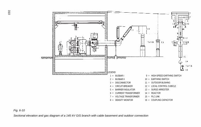
310
Fig. 6-10
Sectional elevation and gas diagram of a 145 kV GIS branch with cable basement and outdoor connection
LEGEND:1 = BUSBAR I2 = BUSBAR II3 = DISCONNECTOR4 = CIRCUIT-BREAKER5 = BARRIER INSULATOR6 = CURRENT TRANSFORMER7 = VOLTAGE TRANSFORMER8 = DENSITY MONITOR
9 = HIGH-SPEED EARTHING SWITCH10 = EARTHING SWITCH11 = OUTDOOR BUSHING12 = LOCAL CONTROL CUBICLE13 = SURGE ARRESTER14 = REACTOR15 = PLC LINK16 = COUPLING CAPACITOR

311
6
Fig. 6-11 shows the plan view of a 123 kV switchyard created by using the CAD system,with double busbars and in-line layout.
Fig. 6-11
123 kV outdoor switching station with double busbars, in-line layout

312
6.4 Drawings
In technical drawings the information required for constructing and operating aninstallation or a station component is given in a font that is “readable” for engineers andtechnicians. The drawings, or these days preferably referred to as documents, aretherefore subject to specific, generally accepted rules and implementation guidelines,which are based on national and international standards. The specifications cover suchitems as:
– Paper formats, paper types– Representation, symbols, characters– Lettering, font sizes– General design, header, metadata– Document types, -identification and -order– Creation of documents, processing– Minimum content of documents
6.4.1 Drawing formats
Table 6-22
A-series formats as per DIN 6771-6, and ISO 5457
Format Size Number of fieldssymbol
cut uncut short side long side
A0 841 x 1189 880 x 1230 16 24A1 594 x 841 625 x 880 12 16A2 420 x 594 450 x 625 8 12A3 297 x 420 330 x 450 6 8A4 210 x 297 240 x 330 4 6
Table 6-23
Continuous formats as per DIN 6771-6
Format Size Number of fieldssymbol
cut uncut short side long side
A2.0 420 x 1189 450 x 1230 8 24A2.1 420 x 841 420 x 880 8 16A3.0 297 x 1189 330 x 1230 6 24A3.1 297 x 841 330 x 880 6 16A3.2 297 x 594 330 x 625 6 12
Continuous formats should be avoided as far as possible.For formats >A0, see DIN 476.
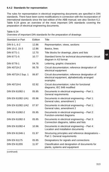
313
6
6.4.2 Standards for representation
The rules for representation in electrical engineering documents are specified in DINstandards. There have been some modifications in connection with the incorporation ofinternational standards since the last edition of the ABB manual; see also Section 6.2.Table 6-24 gives an overview of the most important DIN standards covering thepreparation of electrical engineering documents.
Table 6-24Overview of important DIN standards for the preparation of drawings
Standard or Part Edition Title
DIN 6-1, 6-2 12.86 Representation, views, sections
DIN 15-2, 15-3 12.86 Basics, lines
DIN 6771-1 12.70 Title blocks for drawings, plans and lists
DIN 6771-5 10.77 Standard forms for technical documentation; circuitdiagram in A3 format
DIN 6776-1 04.76 Lettering, graphic characters
DIN 40719-2 06.78 Circuit documentation; reference designation of ˇˇˇˇelectrical equipment
DIN 40719-2 Sup. 1 06.87 Circuit documentation; reference designation of ˇˇˇˇelectrical equipment, alphabetically arranged ˇˇˇˇˇˇˇexamples
DIN 40719-6 02.92 Circuit documentation; rules for functionaldiagrams; IEC 848 modified
DIN EN 61082-1 05.95 Documents in electrical engineering – Part 1:General requirements
DIN EN 61082-1/A1 05.96 Documents in electrical engineering – Part 1:General rules, amendment 1
DIN EN 61082-1/A2 07.97 Documents in electrical engineering – Part 1:General rules, amendment 2
DIN EN 61082-2 05.95 Documents in electrical engineering – Part 2:Function-oriented diagrams
DIN EN 61082-3 05.95 Documents in electrical engineering – Part 3:Connection diagrams, tables and lists
DIN EN 61082-4 10.96 Documents in electrical engineering – Part 4:Location and installation documents
DIN EN 61346-1 01.97 Structuring principles and reference designations –Part 1: General requirements
DIN EN 61175 05.95 Designations for signals and connections
DIN EN 61355 11.97 Classification and designation of documents for plants, systems and equipment
(continued)

314
Table 6-24 (continued)Overview of important DIN standards for the preparation of drawings
Standard or Part Edition Title
DIN EN 60617-2 8/97 Graphical symbols for diagrams; Part 2: Symbol elements and other symbols having generalapplication
DIN EN 60617-3 08/97 Graphical symbols for diagrams; Part 3:Conductors and connecting devices
DIN EN 60617-4 08/97 Graphical symbols for diagrams; Part 4:Basic passive components
DIN EN 60617-5 08/97 Graphical symbols for diagrams; Part 5:Semiconductors and electron tubes
DIN EN 60617-6 08/97 Graphical symbols for diagrams; Part 6:Production and conversion electrical energy
DIN EN 60617-7 08/97 Graphical symbols for diagrams; Part 7:Switchgear, controlgear and protection devices
DIN EN 60617-8 08/97 Graphical symbols for diagrams; Part 8:Measuring instruments, lamps and signalling devices
DIN EN 60617-9 08/97 Graphical symbols for diagrams; Part 9:Telecommunications: switching and peripheralequipment
DIN EN 60617-10 08/97 Graphical symbols for diagrams; Part 10:Telecommunications: transmission
DIN EN 60617-11 08/97 Graphical symbols for diagrams; Part 11:Architectural and topographical installation plans and diagrams
DIN EN 60617-12 04/99 Graphical symbols for documentation; Part 12: Binary logic elements
DIN EN 60617-13 01/94 Graphical symbols for documentation; Part 13: Analogue elements
DIN EN 61360-1 01/96 Standard data element types with associatedclassification scheme for electric components – Part 1:Definitions - principles and methods
DIN EN 61360-2 11/98 Standard data element types with associatedclassification scheme for electric components – Part 2:EXPRESS data model
DIN EN 61360-4 06/98 Standard data element types with associatedclassification scheme for electric components – Part 4:IEC Reference collection of standardized dataelements type, component classes and terms.
On a national german level the recommendations of the IG EVU, i.e. the “EnergyDistribution Group”, have been developed into generally accepted rules with normativecharacter for documentation of plants, process sequences and equipment.
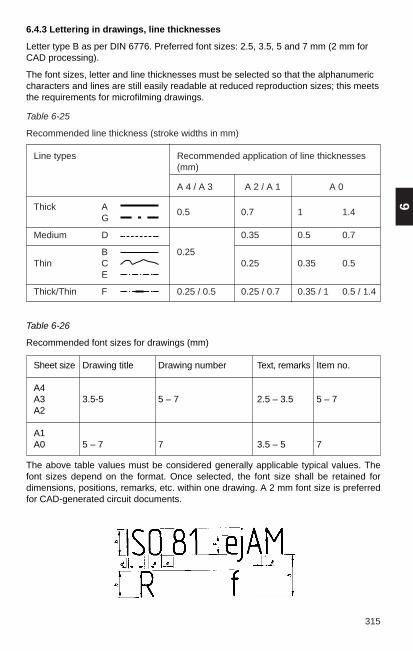
Table 6-25
Recommended line thickness (stroke widths in mm)
Line types Recommended application of line thicknesses(mm)
A 4 / A 3 A 2 / A 1 A 0
Thick A 0.5 0.7 1 1.4G
Medium D 0.35 0.5 0.7
B 0.25Thin C 0.25 0.35 0.5
E
Thick/Thin F 0.25 / 0.5 0.25 / 0.7 0.35 / 1 0.5 / 1.4
315
6
6.4.3 Lettering in drawings, line thicknesses
Letter type B as per DIN 6776. Preferred font sizes: 2.5, 3.5, 5 and 7 mm (2 mm forCAD processing).
The font sizes, letter and line thicknesses must be selected so that the alphanumericcharacters and lines are still easily readable at reduced reproduction sizes; this meetsthe requirements for microfilming drawings.
Table 6-26
Recommended font sizes for drawings (mm)
Sheet size Drawing title Drawing number Text, remarks Item no.
A4A3 3.5-5 5 – 7 2.5 – 3.5 5 – 7A2
A1A0 5 – 7 7 3.5 – 5 7
The above table values must be considered generally applicable typical values. Thefont sizes depend on the format. Once selected, the font size shall be retained fordimensions, positions, remarks, etc. within one drawing. A 2 mm font size is preferredfor CAD-generated circuit documents.

316
6.4.4 Text panel, identification of drawing
A drawing is a document which aids in setting up or operating an installation or a stationcomponent. It must therefore include identifications and data showing its content,status and origins.
– Origin, originator, release– Date of production, if necessary with indication of source in view of patent claims– Drawing number– Subject of drawing (title block)– Modification status– Filing instructions, if appropriate– Scale (for layouts, designs)– Classification
From these indications and by filling out the text panel, it is confirmed that the relevantstandards and quality specifications have been observed.
The identifier drawing number at ABB consists of a minimum of three alpha and sevennumeric characters, whose position provides varying information.
Table 6-27
Font style B (d = h / 10) to DIN 6776
Type Ratio Dimension in mm
Letter heightUpper case (capital) h (10/10) h 2.5 3.5 5 7 10 14 20Lower case (small) c (7/10) h – 2.5 3.5 5 7 10 14(without ascenders/decenders)
Minimum foot spacing a (2/10) h 0.5 0.7 1 1.4 2 2.8 4Minimum line spacing b (14/10) h 3.5 5 7 10 14 20 28Minimum word spacing e (6/10) h 1.5 2.1 3 4.2 6 8.4 12
Stroke width d (1/10) h 0.25 0.35 0.5 0.7 1 1.4 2

317
66
Key to drawing number:
Sequence of symbols N A A A N N N N N N
Example: 1 H D E 3 3 1 2 3 4
Business AreaCode toCS 9 ADA 11
Country code (Germany)
Organization unit: dept. etc.
Organization unit: group etc.
Paper size: A3
Identification number: 0 … 9999
If a drawing consists of several pages, e.g. circuit documentation manual, additionalinformation is required, see Section 6.2.
6.4.5 Drawings for switchgear installations
The drawings are classified in the following groups, according to their function:
– Civil engineering drawings, architectural diagrams – Layout drawings– Design drawings, arrangement drawings, parts lists– Circuit documentation– Tables of contents, lists of drawings
Standard paper sizes are available for the different kinds of drawings, depending ontheir purpose. DIN format A3 with title block conforming to DIN 6771 Part 5 is preferredfor circuit documentation and also for related switchboard arrangement drawings,tables etc.
Layout and design drawings have to be drawn to scale. Format and title block areselected in accordance with DIN 6771-1. Preferred scales are specified for the differentkinds of installation and voltage levels (Table 6-28).

318
Table 6-28
Preferred scales
Design ScaleLayout
Outdoor installationsUp to 525 kV 1 : 500; 1 : 200Up to 245 kV 1 : 200; 1 : 100Up to 145 kV 1 : 100; 1 : 50GIS installations 1 : 50; 1 : 25 (not standardized)Generator busducts 1 : 50; 1 : 20Medium-voltage installations 1 : 20;Cubicles, inside arrangement 1 : 10;Other, details 1 : 5; 1 : 2.5; 1 :1Enlargements 2 : 1; 5 : 1; 10 :1
6.4.6 Drawing production, drafting aids
The following methods are used for economical preparation of documents:
– CAD (Computer-Aided Design and Drafting) with drawings output by plotter, seeSection 6.3
– CAE (Computer-Aided Engineering) with documents generated by computerprograms and output by plotters, see Section 6.3.3, e.g. terminal diagrams, wiringlists, cable tables, etc.
– Drawing reproduction with photomachines
– Computer-aided microfilming (COM system)

7
319
7 Low-voltage Switchgear
7.1 Switchgear apparatus
Low-voltage switchgear is designed for switching and protection of electricalequipment. The selection of switchgear apparatus is based on the specific switchingtask, e.g. isolation, load switching, short-circuit current breaking, motor switching,protection against overcurrent and personnel hazard. Depending on the type,switchgear apparatus can be used for single or multiple switching tasks. Switchingtasks can also be conducted by a combination of several switchgear units. Fig. 7-1shows some applications for LV switchgear.
Fig. 7-1
Examples for use of low-voltage switchgear:
1 Circuit-breaker, general 2 Fuse, 3 Disconnector, 4 Loadbreak switch, 5 Fusedswitch-disconnector, 6 Motor starter (motor protection switch), 7 Contactor, 8Overload relay, 9 Switch disconnector with fuses, 10 Residual current-operated circuit-breaker (RCCB), 11 Miniature circuit-breaker, 12* Residual current-operated circuit-breaker with overcurrent tripping (RCBO), 13* Residual current-operated miniaturecircuit-breaker (RCD)
* Graphic symbols not standardized
7.1.1 Low-voltage switchgear as per VDE 0660 Part 100 and following parts, EN60947 – ... and IEC 60947 – ...
Table 7-1 shows a partial overview of the applicable standards for switchgearapparatus.

320
Circuit-breakers
Circuit-breakers must be capable of making, conducting and switching off currentsunder operational conditions and under specified extraordinary conditions up to thepoint of short circuit, making the current, conducting it for a specified period andinterrupting it. Circuit-breakers with overload and short-circuit instantaneous trippingare used for operational switching and overcurrent protection of operational equipmentand system parts with low switching frequency. Circuit-breakers without overcurrent
Table 7-4 of the utilization categories for contactors already corresponds to IEC60947-4-1, because it has been supplemented with reference DIN VDE. Utilizationcategories for switchgear as per IEC 60947-3 are shown in Tables 7-6 and 7-7.
In accordance with the regulations, for all devices the rated voltages (formerly referredto as nominal voltages) are specified whose insulation voltages are assigned as testvalues. For example, devices up to 690 V have a test value of 2 500 V. The ratedimpulse voltage resistance Uimp must be shown on the switch or be included in themanufacturer’s documentation. The design of a low-voltage system must ensure thatno voltages can occur which are higher than the rated insulation voltages of thedevices.
Table 7-1
Partial overview of the most important standards for low-voltage switchgear
German standard Classification European International1) VDE 06602) standard standard
General specification DIN EN 60947-1 Part 100 EN 60947-1 IEC 60947-1
Circuit-breaker DIN EN 60947-2 Part 101 EN 60947-2 IEC 60947-2
Electromechanical contactorsDIN VDE 660-102 Part 102 EN 60947-4-1 IEC 60947-4-1
and motor starters
Switches, disconnectors,switch-disconnectors DIN VDE 660-107 Part 107 EN 60947-3 IEC 60947-3and fuse combination units
Semiconductor contactors DIN VDE 660-109 Part 109 – IEC 60158-2 mod.
Multifunction equipment,DIN VDE 0660-114 Part 114 EN 60947-6-1 IEC 60947-6-1
automatic transfer switch
Multifunction equipment, controlDIN EN 60947-6-2 Part 115 EN 60947-6-2 IEC 60947-6-2
and protection switching devices
Contactors and motor starters,EN 60947-4-2 IEC 60947-4-2
semiconductor motor controllers DIN EN 60947-4-2 Part 117mod.
and starters for AC
Control devices and switching DIN EN 60947-5-1 Part 200 EN 60947-5-1 IEC 60947-5-1
elements, electromechanicalcontrol circuit devices
1) Current valid designation2) Classification in VDE specifications system

7
321
The major classification criteria of circuit-breakers are
– by utilization categories
A: without short-time grading of delay tripping for selectivity under short-circuitconditions
B: with intended short-time delay of short-circuit tripping (adjustable or non-adjustable)
– by type of arc extinction medium
Air, vacuum, gas
– by design
compact design or „moulded case“ type,open design or „air-break“ type
– by installation type
fixed,draw-out
– by type of arc extinction
current-limiting circuit-breaker,non-current-limiting circuit-breaker
„Moulded case“ circuit-breakers consist of an insulation case that contains thecomponents of the breaker. This type of breaker is designed for rated currents up toabout 3 200 A.
“Open type circuit-breakers” or also “air-break circuit-breakers” do not have a compactinsulation case. They are designed for rated currents up to 6 300 A.
Table 7-2
Preferred values of the rated supply voltage of control devices and auxiliary circuits asper DIN EN 60947-2 (VDE 0660 Part 101)
Us
DC voltage AC single-phase voltage
24 48 110 125 220 250 24 48 110 127 220 230
releases, but with open-circuit shunt release (0,1 to 1,1 Un), are used in meshedsystems as „network protectors“ to prevent reverse voltages.
Circuit-breakers are supplied with dependent or independent manual or poweractuation or with a stored-energy mechanism. The circuit-breaker is opened by manualactuation, electrical actuation by motor or electromagnet, load current, overcurrent,undervoltage, reverse power or reverse current tripping.
Preferred values of the rated control voltage are listed in Table 7-2.

322
b) Ratio n between short-circuit-making and -breaking capacity and associatedpower factor (with alternating current circuit-breakers)as per DIN EN 60947-2 (VDE 0660 Part 101)
Short-circuit-breaking capacity I Power Minimum value for n(rms value in kA) factor n = Short-circuit-making capacity
Short-circuit-breaking capacity
4.5 < I ≤ 6 0.7 1.56 < I ≤ 10 0.5 1.7
10 < I ≤ 20 0.3 2.020 < I ≤ 50 0.25 2.150 < I 0.2 2.2
Non-current-limiting circuit-breakers extinguish the arc at the natural alternating currentzero crossing. The conducting paths are so dimensioned that they can conduct the fullshort-circuit current thermally. All downstream system components are also thermallyand dynamically loaded with the unlimited peak short-circuit current.
Current limiting circuit-breakers interrupt the short-circuit current before it reaches thepeak value of the first half-cycle. The peak short-circuit current is limited to a value (cut-off current ID) that significantly reduces the thermal and dynamic stress on thedownstream components. Fig. 7-2 shows the energy-limiting and current-limitingcharacteristics of a current-limiting circuit-breaker.
Current-limiting circuit-breakers, like fuses, are particularly suitable for short-circuitprotection of switchgear with lower switching capacity (back-up protection).
Rated short-circuit currents: Rated-operating short-circuit current ICS
Test duty: O – t – CO – t – CO
Rated-limiting short-circuit current lCU
Test duty: O – t – CO
O = open; CO = close-open; t = dead time between operations (3 min)
Table 7-3
a) Recommended percentage values for Ics based on Icu
as per DIN EN 60947-2 (VDE 0660 Part 101)
Utilization category A Utilization category B% of ICU % of ICU
25 – 50 50 75 75
100 100

7
323
Fig. 7-2a
Limitation of let-throughpower I2•t by a current-limiting circuit-breaker for In = 630 A with varioustripping settings(R 320 to R 500)
Is = short-circuit current,prospective r.m.s. values
Fig. 7-2b
Limitation of the short-circuit current by acurrent-limiting circuit-breaker for In = 630 A with variousservice voltages
Ip = let-through current,peak current valuesIs = short-circuit current,prospective r.m.s. values
a)
b)
Contactors
Contactors are remote-control switching devices with restoring force, which areactuated and held by their actuator. They are primarily intended for high-switchingfrequency for switching currents with equipment in a healthy state, including operationaloverload. Contactors are suitable for isolation to a limited extent only, and they must beprotected against short circuit by upstream protection equipment.
Apart from the electromagnetic actuation most often used, there are also contactorswith pneumatic or electropneumatic actuation.
Contactors are selected by utilization categories, Table 7-4.
1010
109
108
107
106
105
104
103
102 103 104 105 Is [A]
R500R400
R320
660/690V380/415V
220/230V
1000800
600
400
200
80
60
40
30
20
8
6
4
3
2
300
100
10
11 10 100 1000
660/690V
380/415V
220/230V
Prospectivepeak-value
current
2 3 4 5 6 8 20 30 40 60 80 200 300 400 600 800
I2t [A2s]
Ip [kAp]
Is [kArms]

324
Table 7-4
Utilization categories for contactors as per VDE 0660 Part 102, EN 60947-4-1
Current Utilization Typical applicationtype category
Alternating AC-1 Non-inductive or weak inductive load, current resistance furnaces
AC-2 Slip-ring motors: starting, disconnecting
AC-3 Squirrel-cage motors: starting, disconnecting whilerunning1)
AC-4 Squirrel-cage motors: starting, plug braking,reversing, jogging
AC-5a Switching gas-discharge lights
AC-5b Switching incandescent lights
AC-6a Switching transformers
AC-6b Switching capacitor banks
AC-7a Weakly inductive load in household appliances and similar applications
AC-7b Motor load for household devices
AC-8a Switching hermetically sealed refrigerantcompressor motors with manual reset of the overload release2)
AC-8b Switching hermetically sealed refrigerantcompressor motors with automatic reset of the overload release2)
Direct DC-1 Non-inductive or weakly inductive load, current resistance furnaces
DC-3 Shunt motors: starting, plug braking, reversing, jogging, resistance braking
DC-5 Series motors: starting, plug braking, reversing, jogging, resistance braking
DC-6 Switching incandescent lights
1) Devices for utilization category AC-3 may be used for occasional jogging or plug-braking for alimited period, such as setting up a machine; the number of actuations in these circumstances shallnot exceed five per minute and ten per ten minutes.
2) In the case of hermetically sealed refrigerant compressor motors, compressor and motor aresealed in the same housing without an external shaft or with the shaft sealed, and the motoroperates in the refrigerant.
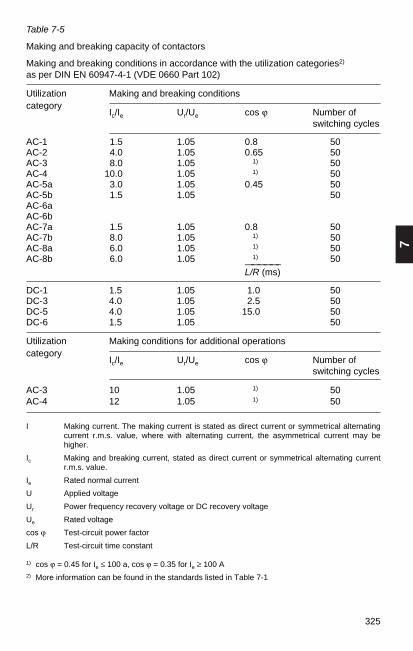
7
325
Table 7-5
Making and breaking capacity of contactors
Making and breaking conditions in accordance with the utilization categories2)
as per DIN EN 60947-4-1 (VDE 0660 Part 102)
Utilization Making and breaking conditionscategory
Ic/Ie Ur/Ue cos ϕ Number ofswitching cycles
AC-1 1.5 1.05 0.8 50AC-2 4.0 1.05 0.65 50AC-3 8.0 1.05 1) 50AC-4 10.0 1.05 1) 50AC-5a 3.0 1.05 0.45 50AC-5b 1.5 1.05 50AC-6aAC-6bAC-7a 1.5 1.05 0.8 50AC-7b 8.0 1.05 1) 50AC-8a 6.0 1.05 1) 50AC-8b 6.0 1.05 1) 50—————–
L/R (ms)
DC-1 1.5 1.05 1.0 50DC-3 4.0 1.05 2.5 50DC-5 4.0 1.05 15.0 50DC-6 1.5 1.05 50
Utilization Making conditions for additional operationscategory
Ic/Ie Ur/Ue cos ϕ Number of switching cycles
AC-3 10 1.05 1) 50AC-4 12 1.05 1) 50
I Making current. The making current is stated as direct current or symmetrical alternatingcurrent r.m.s. value, where with alternating current, the asymmetrical current may behigher.
Ic Making and breaking current, stated as direct current or symmetrical alternating currentr.m.s. value.
Ie Rated normal current
U Applied voltage
Ur Power frequency recovery voltage or DC recovery voltage
Ue Rated voltage
cos ϕ Test-circuit power factor
L/R Test-circuit time constant
1) cos ϕ = 0.45 for Ie ≤ 100 a, cos ϕ = 0.35 for Ie ≥ 100 A2) More information can be found in the standards listed in Table 7-1

326
Fig. 7-3
Permissible one-way control line length when closing contactors
1
10
100
1000
10000
1
2000
20
2
3
5
30
50
200
300
500
3000
5000
2.5
10
100
1000
10000
2.5
2500020000
2000
20
3
5
30
50
200
300
500
3000
5000
4
10
100
1000
10000
20000
40000
4
2000
20
5
30
50
200
300
500
3000
5000
30000
1 10 100 1000 10000701.5
10
100
1000
10000
1.5
15000
2000
20
2
3
5
30
50
200
300
500
3000
5000
2 3 5 20 30 50 200 300 500 2000 5000
Querschnitt (Cu) in mm2 Anzugleistung der Spule: in VA für Schütze mit Wechselspannungsbetätigungin W für Schütze mit Gleichspannungsbetätigung
1 3 5 7 9 1 3 5 7 9 1 3 5 7 9 1 3 5 7 9
660 V - 690 V500 V380 V - 400 V220 V - 230 V
110 V
60 V48 V
24 V
E0
29
1D
G
one-
way
line
leng
th in
m
cross section (Cu) in mm2 coil pick-up power: in VA for contactors with a.c. actuationin W for contactors with d.c. actuation
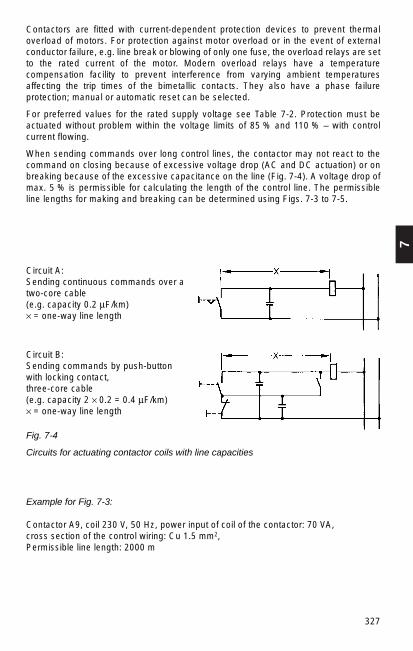
7
327
Circuit A: Sending continuous commands over atwo-core cable (e.g. capacity 0.2 µF/km)× = one-way line length
Circuit B: Sending commands by push-buttonwith locking contact,three-core cable(e.g. capacity 2 × 0.2 = 0.4 µF/km)× = one-way line length
Fig. 7-4
Circuits for actuating contactor coils with line capacities
Contactors are fitted with current-dependent protection devices to prevent thermaloverload of motors. For protection against motor overload or in the event of externalconductor failure, e.g. line break or blowing of only one fuse, the overload relays are setto the rated current of the motor. Modern overload relays have a temperaturecompensation facility to prevent interference from varying ambient temperaturesaffecting the trip times of the bimetallic contacts. They also have a phase failureprotection; manual or automatic reset can be selected.
For preferred values for the rated supply voltage see Table 7-2. Protection must beactuated without problem within the voltage limits of 85 % and 110 % – with controlcurrent flowing.
When sending commands over long control lines, the contactor may not react to thecommand on closing because of excessive voltage drop (AC and DC actuation) or onbreaking because of the excessive capacitance on the line (Fig. 7-4). A voltage drop ofmax. 5 % is permissible for calculating the length of the control line. The permissibleline lengths for making and breaking can be determined using Figs. 7-3 to 7-5.
Example for Fig. 7-3:
Contactor A9, coil 230 V, 50 Hz, power input of coil of the contactor: 70 VA, cross section of the control wiring: Cu 1.5 mm2, Permissible line length: 2000 m
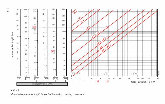
328
Fig. 7-5
Permissible one-way length for control lines when opening contactors
1 10 100 10002 3 5 20 30 50 200 300 5000.10
10
100
1000
10000
20
30
50
200
300
500
2000
3000
5000
0.20
10
100
1000
20
30
50
200
300
500
2000
3000
5000
5
0.30
10
100
1000
3.3
5
20
30
50
200
300
500
2000
3300
0.40
10
100
1000
2.5
5
20
30
50
200
300
500
20002500
0.50
10
100
1000
2
3
5
20
30
50
200
300
500
2000
0.06
380 V - 400 V
660 V - 690 V
220 V - 230 V
110 V
60 V48 V
24 V
500 V
Halteleistung der Spule, in VAKapazität der Leitung in µF/km
10
100
1000
21.7
3
5
20
30
50
200
300
500
1700
1 3 5 7 9 1 3 5 7 9 1 3 5 7 9
380
60
188
E0292D
G
one-
way
line
leng
th in
m
line capacitance, in µF/kmholding power of coil, in VA
7
329
Example A for Fig. 7-5: Example B for Fig. 7-5:
Contactor A 16, coil Uc = 500 V, 50 Hz, Contactor A 50, coil Uc = 230 V, 50 HzHolding power of coil: 8 VA. Holding power of coil: 18 VA.
Circuit with push-buttonContinuous command via commands and locking contacttwo-core cable three-core cable with a capacitywith a capacity of 0.2 µ F/km of 2 x 0.2 µ F/km = 0.4 µ F/kmMax. permissible line length: 60 m Max. permissibleble line length: 380 m
Motor starter
The motor starter is the term for the combination of all devices required for starting andstopping a motor in connection with appropriate overload protection.
Compact, manually operated motor starters, also referred to as motor protectionswitches, are suitable for switching short-circuit currents if they meet the conditions forcircuit-breakers.
Motor starters can be actuated manually, electromagnetically, by motor, pneumaticallyand electropneumatically. They are suited for operation with open-circuit shuntreleases, undervoltage relays or undervoltage tripping releases, delayed overloadrelays, instantaneous overcurrent relays and other relays or releases.
The rated normal current of a motor starter is dependent on the rated operating voltage,the rated frequency, the rated operating duty, the utilization category (Table 7-4) and thetype of housing.
Other switchgear apparatus (DIN VDE 0660 Part 107)
Disconnector
Switching devices that for safety purposes has isolating distances in the open positionin conformity with specific requirements. A disconnector can only open and close acircuit if either a current of negligible quantity is switched off or on, or if there is nosignificant voltage difference between the two contacts of each pole. It can conductnormal currents under normal conditions and larger currents under abnormalconditions, e. g. short-circuit currents, for a specific period.
Note 1:Currents of negligible quantity are capacitive currents, which occur at bushings,busbars, very short cables and the currents from voltage transformers andvoltage dividers used for measurement purposes.There is no significant voltage difference in circumstances such as shuntingvoltage-regulating transformers or circuit-breakers.
Note 2:Disconnectors can also have a specific making and/or breaking capacity.

Load-break switch
Switching device that under normal conditions in the current circuit, if applicable withspecified overload conditions, can make, conduct and break currents and that underspecified abnormal conditions such as short circuit can conduct these currents for aspecified period.
Note:
A load-break switch may have a short-circuit-making capacity, but no short-circuit-breaking capacity.
Switch-disconnector
Load-break switch that meets the isolating requirements specified for a disconnector inthe open position.
Disconnection (isolating function)
Function for isolating the voltage supply of the entire switchboard or system part, inwhich the switchboard or system part is disconnected from all energy sources for safetyreasons.
Fuse combination unit
Load-break switch, disconnector or switch-disconnector and one or more fuses in a unitassembled by the manufacturer or in accordance with the manufacturer’s directions.
Disconnector with fuses
Unit comprising disconnector and fuses, in which one fuse is switched in series with thedisconnector in one or more phases.
Load-break switch with fuses
Unit comprising load-break switch and fuses, in which one fuse is switched in serieswith the load-break switch in one or more phases.
Fuse-disconnector
Disconnector in which a fuse link or a fuse holder with fuse link forms the movablecontact piece.
Fuse-switch disconnector
Switch-disconnector in which a fuse link or a fuse holder with fuse link forms themovable contact piece.
330

7
331
Note 1:The fuse may be located on both sides of the contacts or permanently fixedbetween the contacts.
Note 2:All switches must have single break or multiple break operation
Note 3: The graphic symbols correspond to IEC 60617-7
Various switching mechanisms
Dependent manual actuation
Actuation exclusively by human effort, so speed and power for the switching movementdepend on the operator.
Independent manual actuation
Actuation by a stored-energy mechanism, in which the energy applied manually isstored as tension and released during the operating motion, so speed and power for theswitching movement are independent of the operator.
Stored-energy operation
Actuation by energy stored in the actuating mechanism, which is sufficient to completethe switching operation under specific conditions. The energy is stored before theactuation begins.
Note:
Stored-energy mechanisms are differentiated by:1. the type of energy storage (spring, weight etc.);2. the type of energy source (manual, electrical etc.);3. the type of energy release (manual, electrical etc.).
Table 7-6
Utilization categories for switchgear as per VDE 0660 Part 107, EN 60947-3 foralternating current
Utilization category
frequent occasional typical application casesoperation operation
AC-20A*) AC-20B*) close and open without loadAC-21A AC-21B switching resistive load including
minor overloadAC-22A AC-22B switching mixed resistive and inductive
load including minor overloadAC-23A AC-23B switching motors or other highly
inductive load
*) See Table 7-7!

332
Table 7-7
Utilization categories for switchgear as per VDE 0660 Part 107, EN 60947-3for direct current
Utilization category
frequent occasional typical application casesoperation operation
DC-20A*) DC-20B*) close and open without load DC-21A DC-21B switching resistive load including
minor overload DC-22A DC-22B switching mixed resistive and inductive
load including minor overload(e. g. shunt motors)
DC-23A DC-23B switching highly inductive load (e. g. series motors)
*) Application of these utilization categories are not permitted in the USA.Utilization categories with B apply for devices that are only switched occasionally in accordance withtheir design or application. Examples are disconnectors that are only operated for disconnectionduring maintenance work or switching devices in which the contact blades of the fuse links form themovable contact.
Table 7-8
Verification of rated making capacity and rated breaking capacity. Conditions for making and breaking in accordance with utilization categories as per VDE 0660 Part 107, EN 60947-3
Current Utilization Ie Making1) Breakingtype category A I/Ie U/Ue cos ϕ Ic/Ie Ur/Ue cos ϕ
Alternating AC-20 all values 2) 1.1 2) 2) 1.1 2)
current AC-21 all values 1.5 1.1 0.95 1.5 1.1 0.95AC-22 all values 3 1.1 0.65 3 1.1 0.65AC-23 ≤ 17 10 1.1 0.65 8 1.1 0.65
17 < Ie ≤ 100 10 1.1 0.35 8 1.1 0.35> 100 83) 1.1 0.35 6 1.1 0.35
Current Utilization Ie I/Ie U/Ue L/R Ic/Ie Ur/Ue L/Rtype category A (ms) (ms)
Direct DC-20 all values 2) 1.1 2) 2) 1.1 2)
current DC-21 all values 1.5 1.1 1 1.5 1.1 1DC-22 all values 4 1.1 2.5 4 1.1 2.5DC-23 all values 4 1.1 15 4 1.1 15
I making currentIc breaking currentIe rated normal currentU voltage before makingUe rated operating voltageUr recovery voltage (between the terminals of the switching device)1) With alternating current, the making conditions are expressed as rms values, where the peak value of the
asymmetrical current can take a higher value depending on the power factor of the current circuit.2) If the switching device has a making and/or breaking capacity, the values of the current and of the
power factor (time constant) must be stated by the manufacturer.3) However it must be at least 1000 A.

346
7.2 Low-voltage switchgear installations and distribution boards
7.2.1 Basics
Low-voltage switchgear installations and distribution boards are used for powerdistribution, motor power supply and to supply building services.
Depending on the application, they include equipment for switching, protecting,conversion, control, regulation, monitoring and measurement. Because of theextremely varied applications and requirements – from operation of the distributionboards by untrained personnel to operation by trained electrical specialists inelectrically seperated control rooms – different enclosure designs and equipmentcombinations tailored for the specific requirements are required. These applications aredescribed in numerous standards and design regulations (Table 7-17).
↓VDE 0100 Erection of power installations with rated voltages up to 1000 V
↓VDE 0100 Part 729 Installation and connection of switchgear and controlgear and distribution boards
↓↓
↓ ↓↓ ↓ ↓
↓
↓
↓
Construction and design regulations
VDE 0603Consumer units andmeter panels
Part 501IEC 60439-4Assemblies forconstruction sites
BV
Part 502IEC 60439-2Busbar trunkingsystems
SV
Part 503IEC 60439-5Cable distributioncabinets
KVS
Part 504IEC 60439-3Access for use byunskilled persons
TSKL
Part 505House connectionboxes andfuseboxes
HA/SK
Part 506Slotted trunking
VK
Part 512Low-voltagesubstationdistribution boards
SK/NS
Part 507IEC 60890Determiningtemperature rise
PTSK
Part 500 Supplement 2IEC 61641Guide for testing under internal arcfault conditions
Part 509IEC 61117Determining short-circuitwithstand strength
PTSK
DIN EN 60439-1 (VDE 0660 Part 500) IEC 60439-1
Enclosed low-voltage switchgear and controlgear assemblies (SK)
Table 7-17
Construction and design regulations for low-voltage switchgear installations anddistribution boards
VDE 0107/0108 Regulations for installations in hospitals and buildings forcommunal facilities
↓
↓VDE 0100 Part 410 Protection for safety; Protection against electric shock
VDE 0106 Part 100 Protection against electric shock; Actuating memberspositioned close to parts liable to shock
Protection against direct contactComplete by insulationbarrier/sheath (cubicle andenclosure systems) degree of protection min. IP 2X
additional protection in caseof indirect contact• by tripping or message over
equipment earthingconductor safety class I
• by total insulationsafety class II
• by protective separationsafety class III
protection in case ofdirect contact byfault currentprotection deviceI∆ n ≤ 30 ma

7
347
Apart from the small distribution boards, all other low-voltage switchgear installationsand distribution boards are considered under the heading low-voltage switchgearassemblies in the standard DIN EN 60439-1 (VDE 0660 Part 500) and the provisions inits subheadings. The base standard specifies the terms, the subdivision and themanufacturer’s instructions for the designation of switchgear assemblies and also theoperating and environmental conditions, the specified requirements and the testing(type and routine tests).
In recent years, the dimensions of switchgear assemblies have a basic grid of 25 mm(as per DIN 43 660) for flexible internal structure and for modular design. Thistechnology provides the prerequisite for economical planning and manufacture ofsystems and simplifies later conversion in the event of changes and extensions. Thepreferred external dimensions are specified in the DIN 41485 standard.
7.2.2 Standardized terms
Only the most basic terms of the many specified in the DIN EN 60 439-1 (VDE 0660Part 500) standard are listed below.
– Switchgear assembly (SK) Combination of one or more low-voltage switching deviceswith associated equipment for control, measurement, monitoring and the protectionand process control units etc., fully assembled under the manufacturer’s supervision,with all internal electrical and mechanical connections and design parts.
Note The manufacturer of the complete switchgear assembly has fullresponsibility also in case of the installation of purchased type-testedunits/functional modules.
– Type-tested low-voltage switchgear assembly (TSK//TTA = type tested assembly):low-voltage switchgear assembly not substantially different from the original type orsystem of the switchgear assembly that was type-tested according to the standard.
Note This allows specified assembly work to be done outside the productionpremises of the manufacturer of the assembly for shipping andmanufacturing reasons.
– Partially type-tested low-voltage switchgear assembly (PTSK//PTTA = partially type-tested assembly): low-voltage switchgear assembly (SK) consisting of type-testedand not type-tested modules derived from type-tested modules that have passed therelevant test.
Note Instead of the derivation from type-tested modules, the retention of thetemperature rise limit as per VDE 0660 Part 507 and the short-circuitcurrent capability as per VDE 0660 Part 509 may both be confirmed bycalculation. A module can comprise one single switching device with theassociated electrical and mechanical connections or one singleenclosure.
The distinction between TSK and PTSK by the standard does not mean a subdivisioninto two classes of different quality. Both designs are equal.

348
The following configurations are among those standardized as units of switchgearassemblies:– Section: unit of a switchgear assembly between two sequential vertical limit levels.– Sub-section: unit of a switchgear assembly between two horizontal limit levels
positioned one above the other in a section.– Compartment: section or sub-section that is fully enclosed, except for the openings
required for connections, control or ventilation.– Functional unit: part of a switchgear assembly with all electrical and mechanical
components required to meet the same function.– Fixed part: a rack of equipment assembled and wired on a common support for fixed
installation.
Note: cannot be removed under voltage, even if the rack is designed to beinserted on the supply side.
– Removable part: unit that can be removed from the switchgear assembly andreplaced as a whole, even when the current circuit to which it is connected is live.
– Withdrawable part: removable part that can be placed in a position where an isolatingdistance is open while it is still mechanically connected to the switchgear assembly.
– Type tests: type tests are used to confirm compliance with requirements specified inthe standards. Type tests are conducted on an example of a switchgear assembly oron those parts of switchgear assemblies that are repeatedly manufactured in thesame or similar type. The tests must be conducted or commissioned by themanufacturer. The testing laboratory prepares a test certificate.
– Routine testing: routine testing is used to detect any material and manufacturingdefects. Routine testing is conducted on every new switchgear assembly afterassembly or on every transport unit. A second round of routine testing at the set-uparea is not required. Conducting routine testing at the manufacturing plant does notrelease the installer of the switchgear assembly from the obligation of a visualinspection of the switchgear assembly after transportation and after erection.
7.2.3 Classification of switchgear assemblies
The variety of applications results in many different designs of low-voltage switchgearassemblies. They can be classified under different criteria. These criteria must be usedto select a switchgear assembly suitable for the basic requirements of the specificapplication (Table 7-18).

7
349
Open-type assembly
Dead-front assembly
Enclosed assembly
Cubicle-type assembly
Multiple cubicle-type assembly
Desk-type assembly
Box-type assembly
Multiple box-type assembly
Busbar trunking system
External design
Indoor installation
Outdoor installation
Stationary
Movable
Conditions ofinstallation
without enclosure/cover
with enclosure/cover
metal
insulation
Enclosure/Cover
Indoor installation
Outdoor installationmin. IPX3
IP degree of protection
on fixed partinstalled devices
mounting frame
mounting plate
on removable partinstalled devices
with disconnectedposition after removalfrom assembly
with disconnectedposition while withinassembly (withdrawablepart design)
Installation of devices
Protection against direct contact
Full by insulation/barrier/sheath
Partial byobstacles/clearance
Additional by FI circuit breaking
Protection in case ofindirect contact
by tripping or indicationwith protective conductor(class I)
by protective insulation (class II)
by protective separation(class III)
Protective measures(as per VDE 0100 Part 410)
Classification of switchgear assemblies
Basic requirements
a b dc e f g
Table 7-18
Classification of switchgear assemblies by basic requirements
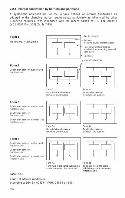
350
7.2.4 Internal subdivision by barriers and partitions
A systematic nomenclature for the various options of internal subdivision asadapted to the changing market requirements, particularly as influenced by otherEuropean countries, was introduced with the recent edition of DIN EN 60439-1(VDE 0660 Part 500) (Table 7-19).
Form 1
No internal subdivision
Form 2Subdivision between busbars andfunctional units
Form 3Subdivision between busbars andfunctional units
Subdivision between functional units
Subdivision between terminals andfunctional units
Form 4Subdivision between busbars andfunctional units
Subdivision between functional units
Subdivision between terminals andfunctional units
Key to symbols:
Busbars, including multiterminal busbars
Functional unit(s) includingterminals for connecting externalconductors
Enclosure
internal subdivision
Form 2bSubdivision betweenterminals and busbars
Form 2aNo subdivision betweenterminals and busbars
Form 3aNo subdivision betweenterminals and busbars
Form 3bSubdivision betweenterminals and busbars
Form 4bTerminals not in the samesubdivision as the connectedfunctional unit
Form 4aTerminals in the same subdivisionas the connected functional unit
Table 7-19
Forms of internal subdivision according to DIN EN 60439-1 (VDE 0660 Part 500)

7
351
7.2.5 Electrical connections in switchgear assemblies
A classification with three letters for identifying the connection technology on fixedparts, removable parts and withdrawable parts is in preparation as Ammendment 12(draft May 1993) to DIN EN 60439-1 (VDE 0660 Part 500). It works as follows
– the first letter refers to the connection point of the supply side of the main circuits,
– the second letter refers to the connection point of the feeder side of the main circuit,
– the third letter refers to the type of connection of the auxiliary circuits.
The following letters are used:
– the letter F for fixed connections (can only be connected or disconnected with tools)
– the letter D means connections that can be released by manual action (without tool),e.g. plug connectors
– the letter W means withdrawable part connections that are automatically connectedor disconnected during insertion or withdrawal.
This means that three items are required to determine terminal connections precisely:
– example 1: FFF = fixed-part design
– example 2: WWW = withdrawable-part design
– example 3: WFD = removable-part design
– example 4: DFF = fixed-part design
7.2.6 Verification of identification data of switchgear assemblies
The high degree of safety of a switchgear assembly must be assured by verification oftype tests and routine testing by the manufacturer. Table 7-20 shows the verificationsand tests required for a type-tested switchgear assembly or partially type-testedswitchgear assembly. In general, the user includes the requirements in the request forproposals. The manufacturer may select the type of verification depending onmanufacturing technology or economical criteria.

352
Table 7-20
Verifications that the technical requirements for type-tested low-voltage switchgearassemblies (TTA) and partially type-tested l.v. switchgear assemblies (PTTA) are met
PTSK
Verification that temperaturerise limits are not exceeded bytesting, extrapolation of TSKor as per VDE 0660 Part 507
Verification of dielectricwithstand as in section 8.2.2or verification by dielectrictest as in section 8.3.2 orverification of insulationresistance as in section8.3.4 (see seq. no. 11)
Verification of short-circuitcurrent withstand strength bytesting, extrapolation of similartype-tested configurations oras per VDE 0660 Part 509
Verification of intactconnection between
exposed conductive parts ofswitchgear assembly andprotective conductor bychecking or resistance test
Verification of short-circuit currentwithstand strength of protectiveconductor by testing orcorresponding design andconfiguration of the protectiveconductor (see section 7.4.3.1.1. lastparagraph1)
Verification of creepagedistance and clearances
Verification of mechanicalfunction
Verification of IP degree ofprotection
Visual inspection ofswitchgear assembly incl.wiring and if applicableelectrical function test
Dielectric withstand test orverification of insulating resistance asin section 8.3.4 (see seq. no. 11)1)
Checking protectivemeasures
Verification of insulationresistance if not tested as insection 8.2.2 or 8.3.2 (see seq.no. 2 & 9)1)
TSK
Verification of non-exceeding of temperaturerise limits by testing
Verification of dielectricwithstand by testing
Verification of short-circuitcurrent withstand strengthby testing
Verification of intactconnection between
exposed conductive parts ofswitchgear assembly andprotective conductor bychecking or resistance test
Verification of short-circuitcurrent withstand strength ofthe protective conductor bytesting
Verification of creepagedistance and clearances
Verification of mechanicalfunction
Verification of IP degree ofprotection
Visual inspection ofswitchgear assembly incl.wiring and if applicableelectrical function test
Dielectric withstand test
Checking protective measuresand visual inspection ofelectrical continuity of theelectrical protective conductorconnection
–
Seq.no.
1
2
3
4
5
6
7
8
9
10
11
Requirements to be tested
Temperature rise limit
Dielectric withstand
Short-circuit currentwithstand strength
Effectiveness of theprotective conductor
Proper connectionbetween exposedconductive parts of theswitchgear assembly andprotective conductor
Short-circuit currentwithstand strength of theprotective conductor
Creepage distance andclearances
Mechanical function
IP degree of protection
Wiring,electrical function
Dielectric withstand
Protective measures
Insulation resistance
Section1)
8.2.1
8.2.2
8.2.3
8.2.4
8.2.4.1
8.2.4.2
8.2.5
8.2.6
8.2.7
8.3.1
8.3.2
8.3.3
8.3.4
Ro
uti
ne
te
sti
ng
Ty
pe
te
sts
Te
sts
1) DIN EN 60439-1 (VDE 0660 Part 500)

7
353
7.2.7 Switchgear assemblies for operation by untrained personnel
The special requirements for switchgear assemblies to which untrained personnel haveaccess for control purposes, also referred to as “distribution boards”, are covered byDIN VDE 0660-504 (VDE 0660 Part 504) in connection with Ammendment DIN EN60 439-3/A1 (VDE 0660 Part 504/A1).
Rated voltages of up to 300 V (AC against earth) and rated currents of up to 250 A areapproved for these applications. There are some additional requirements in the contextof type testing and verifications, such as:– shock resistance of enclosure– rust resistance– resistance of insulation materials against heat and– resistance of insulation materials against excessive heat and fire.
7.2.8 Retrofitting, changing and maintaining low-voltage switchgear assemblies
As per DIN EN 60439-1 (VDE 0660 Part 500), older switchgear assembliesmanufactured before the beginning of the validity of the standard in its current versiondo not require retrofitting.
If a switchgear assembly is changed or retrofitted, the requirement for a test dependson the nature and scope of the intervention and must be decided on a case by casebasis. Fundamentally, anyone who makes a change or retrofit takes over themanufacturer’s responsibility.
The manufacturer must always set maintenance and service schedules. If theswitchgear assembly is not continuously monitored by a qualified electrician, VBG 4(accident prevention regulations of the German professional association of precisionmechanical and electrical technology, April 1996) in Table 1 “Testing electrical systemsand stationary equipment” requires a test at least every 4 years. The test must beconducted by an electrical technician.
7.2.9 Modular low-voltage switchgear system (MNS system)
Cost-effective, compact switchgear systems require design and productiondocumentation for functional units in the form of modules that can be combined asnecessary (combination modules). The basis for the design is a basic grid dimension Eof 25 mm (DIN 43660) in all three dimensions (height, width, depth). Fig. 7-14 gives anoverview of the modular arrangement options and the usable bay dimensions of theMNS system.
Fig. 7-14
The most common dimensions of sections of the MNS system1 to 3 = single control, 4 = double control (duplex), G = equipment compartment, K = cable terminal compartment, S = busbarcompartment (preferred dimensions underlined)
B T H
400600 400 2200800 600
1000 8001200 1000
1200
Dimensions in mm

354
The standardized subdivision of a section into various functional compartments, i.e.equipment compartment, busbar compartment and cable terminal compartment, offersadvantages not just for design but also in operation, maintenance, change and alsosafety.
The basic design of a section with the configuration of the busbars and the distributionbusbars for supplying power to fixed, removable or withdrawable parts is shown in Fig.7-15. A particular advantage of the MNS system is the configuration of the busbars atthe rear of the section (in contrast to the formerly common configuration above in thesection). It offers supplementary safety for personnel in the event of an accidental arcon the busbar, provides space for two busbar systems if required, enables anadvantageous back-to-back configuration with only one busbar system and allowscables to be fed in through cable racks from above.
Distributionbusbars(angle section)
Busbar system 1
Busbar system 2
Distributionbusbars(flat section)
Fig. 7-15
MNS switchgear systemBusbar systems anddistribution busbars
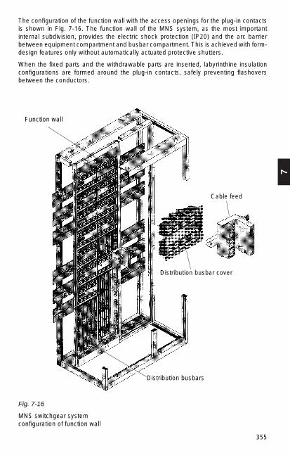
7
355
The configuration of the function wall with the access openings for the plug-in contactsis shown in Fig. 7-16. The function wall of the MNS system, as the most importantinternal subdivision, provides the electric shock protection (IP20) and the arc barrierbetween equipment compartment and busbar compartment. This is achieved with form-design features only without automatically actuated protective shutters.
When the fixed parts and the withdrawable parts are inserted, labyrinthine insulationconfigurations are formed around the plug-in contacts, safely preventing flashoversbetween the conductors.
Fig. 7-16
MNS switchgear systemconfiguration of function wall
Function wall
Cable feed
Distribution busbar cover
Distribution busbars

356
Fixed and withdrawable parts basically have plug-in contacts as busbar-side terminals.In fixed parts the equipment is arranged two-dimensionally on the functional units, whileit has a three-dimensional design in withdrawable parts with maximum usage of thecabinet depth. With a majority of smaller modules (<7.5 kW), the demands on switchcabinet volume are around 40 % less with the withdrawable part design. Thewithdrawable part sizes are adjusted to one another to enable small and large modulesto be economically combined in one bay (Fig. 7-17). Later changes of the componentscan be made without accessing the bay function wall. Reliable mechanical andelectrical interlocking of the switchgear prevents operating errors when moving thewithdrawable parts.
Fig. 7-17
Bay types of the MNS systema) and b) cutaway view and view of MNS sections with circuit-breakers
1 arc partition, 2 busbar compartment, 3 primary busbar, 4 distributionbusbar, 5 instrument recess, 6 circuit-breaker and 7 cable terminalcompartment
c) MNS section with power output modules in strip formd) MNS section with withdrawable unitse) Control switch for withdrawable unit
a b
c d
e
Description of switch positions= operating position, main switch on,
withdrawable part cannot be moved.= main switch off, control voltage circuit
open, withdrawable part cannot bemoved.
= test position, main switch off, controlvoltage circuit closed, withdrawablepart cannot be moved.
= position for moving the withdrawablepart, main and control voltage circuitopen.
= isolated position, withdrawable partwithdrawn by 30 mm (to stop), mainand control contact open,withdrawable part mechanicallylocked.

7
357
The circuit diagrams of typical motor starters, which can be obtained as fixed orwithdrawable parts, are shown in Fig. 7-18. Tables 7-21 and 7-22 have an initialselection of the associated module sizes. MNS assemblies can be supplied as arc-resistant, shock-resistant, vibration-resistant and earthquake-resistant as required forspecific quality demands. Table 7-23 shows an overview of the breadth of application ofthe system.
Fig. 7-18
Examples of standard modules with circuit diagrams for motor startera) with fuse switch-disconnector and thermal relay (fixed-part technique)b) with circuit-breaker and thermal relay (withdrawable-part design)c) with load-break switch, fuse, thermal relay and reversing
(withdrawable-part design)
a b c
Table 7-21
Standard type program motor starter with HRC fuses, with thermal relay
Rated currentIe
(AC3/400 V~)A
11.515.53044607285
105140205295370460
Motor ratings under AC3(occasional jog mode 0.5%under AC4 permissible) at
400 V~kW
5.57.5
15223037455575
110160200250
Module dimensionsHeightOnedirectionof rotation
5 E5 E 5 E 7 E7 E7 E
11 E17 E17 E23 E29 E31 E31 E
With reversing
5 E5 E7 E9 E9 E9 E
11 E17 E17 E23 E37 E39 E–
500 V~kW
5.57.5
15303745597590
132200250355
690 V~kW
5.57.5
15303740–
110110160250355355
Basic grid dimension E = 25 mm

358
Table 7-22
Standard type program motor starter with circuit-breaker, with thermal relay
Rated currentIe
(AC3/400 V~)A
3.55
11.515.53044607285
105140205295370460
Motor ratings under AC3(occasional jog mode 0.5%under AC4 permissible) at
400 V~kW
1.52.25.57.5
15223037455575
110160200250
Module sizeHeightOnedirection ofrotation
8E/48E/48E/48E/48E/48E/48E/28E8E
16E16E16E24E24E24E
With reversing
8E/48E/48E/48E/48E/48E/48E/28E8E
16E16E16E24E––
500 V~kW
1.52.25.57.5
15303745597590
132200250355
690 V~kW
–––––––
4075
110110160250355355
Basic grid dimension E = 25 mm
Table 7-23
Type-tested switchgear assembly MNSSystem characteristic data
Electrical parameters
Rated rated insulation voltage Ui 1000 V 3~, 1500 V voltages rated operational voltage Ua 690 V 3~, 750 V–
rated impulse withstand voltage Uimp 8 kVovervoltage category IIIpollution severity 3rated frequency to 60 Hz
Rated busbars:currents rated current Ie to 6300 A
rate peak withstand current Ipk to 250 kArated short-time withstand current Icw to 100 kA
distribution busbars:rated current Ie to 2000 Arate peak withstand current Ipk to 165 kArated short-time withstand current Icw to 86 kA
(continued)

7
359
For particularly demanding control tasks in industrial plants with a large number ofsmaller mechanisms with high switching frequency, such as is found in power plants,ProMNS system withdrawable parts can be used in MNS low-voltage substations.These have thyristor power controllers as primary switching device for power of up to5.5 kW. This makes them maintenance-free and suitable for virtually unlimitedswitching frequency. The heat produced by the semiconductor modules is dissipated tothe ambient air primarily via cooling fins at the front of the withdrawable part. Thewithdrawable part also includes fuses as additional short-circuit protection and aswitch-disconnector for isolation. For higher outputs, there are also ProMNSwithdrawable parts with power contactors instead of the thyristor controllers.
Table 7-23 (continued)
Mechanical parameters
Dimensions cubicles and supporting structure DIN 41488preferred module sizes, height 2200 mmpreferred module sizes, width 400, 600, 800,
1000, 1200 mmpreferred module sizes, depth 400, 600, 800,
1000, 1200 mmbasic grid dimension E = 25 mm as per
DIN 43660hinged frame for installation DIN 41494, Sheet 1,of electronics tiers ASA C 83.9
Surface supporting structure Al-Zn coatingprotection internal subdivision Al-Zn coating
cross section galvanisedenclosure paint RAL 7032,
pebble grey
Degrees of as per IEC 60529 or DIN 40050 IP 00 to IP 54protection
Plastic parts CFC and halogen-free, DIN VDE 0304 Part 3flame-retardant, self-extinguishing
Internal section - sectionsubdivision busbar compartment-cable terminal compartment
busbar compartment-equipment compartmentequipment compartment-cable terminal compartmentsub-section - sub-section
Specifications IEC 60439-1, EN 60439-1, VDE 0660Part 500, BS5486, UTE63-410
Special German Lloyd, Hamburg (shipping)qualification Pehla Test Laboratory, Ratingen
(internal arcing as per IEC 60298, Appendix AA and VDE 0660 Part 500 Supplement 2)KEMA, Arnheim NL (internal arcing)Federal Ministry for Regional Planning, Building and UrbanDevelopment, Bonn (shelters)ABB testing laboratory, Mannheim (induced vibrations, KTA 2201.1 and 2201.4, DIN IEC 60068 Part 2)

360
7.2.10 Low-voltage distribution boards in cubicle-type assembly
For smaller distributors with busbar currents to 1600 A, there are specially designedcabinet solutions with sheet steel enclosures (protective earthing, safety class I, Fig. 7-19) and also with insulated enclosures (protective insulation, safety class II, Fig. 7-20).The cabinet and enclosure sizes are modular in design, enabling the elements to becombined economically with one another.
Fig. 7-19
Sheet steel distribution board KNS-Swith power output modules in stripform (vertical)
Fig. 7-20
Insulated distribution board KNS-I with cable compartment

7
361
Table 7-24 Technical data of KNS-S and KNS-I distribution boards in cubicle-type assembly
KNS-S KNS-I
Electrical rated operational voltage 690 V 3 ~ 690 V 3 ~parameters rated insulation voltage 1000 V 3 ~, 1200 V– 1000 V 3 ~, 1200 V–
rated frequency to 60 Hz to 60 Hz
rated current of the busbars to 1600 A to 1250 Arated peak-withstand current of the busbars to 90 kA to 90 Karated short-time-withstand current (1s) of the busbars to 45 kA to 45 kA
Dimensions cubicles height 1300, 1900 mm 500, 1000, 2000 mmwidth 400, 700, 1000 mm 350, 650, 950 mmdepth 300, 400, 600 mm 200, 400 mm
basic grid dimension E = 25 mm as per DIN 43660 E = 25 mm as per DIN 43660
Dimensions – enclosure sheet steel RAL 7035, light grey insulation* RAL 9011, black– device coverings fibre glass reinforced polyester fibre glass reinforced polyester
RAL 7035, light grey RAL 7035, light grey– rear walls sheet steel AIZn (Al-Zn) Resopal RAL 7032, pebble grey– base sheet steel RAL 7035, light grey sheet steel RAL 7035, light grey
sheet steel, aluminiumRAL 7035, light grey
Protective measures safety class I safety class II
Degrees of protection as per IEC 60529, DIN 40050 IP 30, IP 40, IP 55 IP 30, IP 40, IP 54
Specifications type-tested switchgear assembly (TSK) IEC 60439-1, EN 60439-1 IEC 60439-1, EN 60439-1and partially type-tested switchgear VDE 0660 Part 500 VDE 0660 Part 500assembly (PTSK)
fire behaviour VDE 0304 Part 3, Level BH 2
Shock safety Application for civil defence sheltersto control class RK0.63/6.3 Degree of safety B
* Polyurethane hard integral foam, without CFC component and chlorine-free

362
7.2.11 Low-voltage distribution boards in multiple box-type assembly
The INS box system has housings of high-quality plastic (polycarbonate), placing it insafety class II. It can be used with busbar currents of up to 1000 A. Fig. 7-21 showsexamples of the structure of housings with flange mountings, Table 7-25 shows how theINS system can be used.
Fig. 7-21
INS insulated distributor system inmultiple box-type assembly
1 Wedge2 Cotter way3 Self-adhesive gasket4 Flange mounting
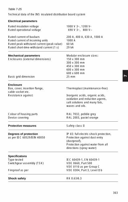
7
363
Table 7-25
Technical data of the INS insulated distribution board system
Electrical parameters
Rated insulation voltage 1000 V 3~, 1200 V- Rated operational voltage 690 V 3~, 800 V–
Rated current of busbars 200 A, 400 A, 630 A, 1000 ARated current of incoming units 1000 ARated peak withstand current (peak value) 60 kARated short-time-withstand current (1 s) 29 kA
Mechanical parameters Modular enclosure sizes:Enclosures (external dimensions) 150 x 300 mm
300 x 300 mm450 x 300 mm600 x 300 mm600 x 600 mm
Basic grid dimension 25 mm
EnclosureBox, cover, insertion flange, Thermoplast (maintenance-free)cable socket etc.Resistance against: Inorganic acids, organic acids,
oxidation and reduction agents,salt solutions and many fats, waxes and oils.
Colour of housing parts RAL 7032, pebble greyDevice covering RAL 2003, pastel orange
Protective measures Safety class II
Degrees of protection IP 65: full electric-shock protection,as per IEC 60529/DIN 40050 Protection against dust entry
(dustproof),Protection against water from all directions (spray water)
SpecificatonsType-tested IEC 60439-1, EN 60439-1Switchgear assembly (TSK) VDE 0660, Part 500
VDE 0110 as per Group CFireproof as per VDE 0304, Part 3, Level II b
Shock safety RK 0.63/6.3

364
The heat generated in the built-in devices (Section 7.3.1) and the heat sources in thesurroundings are particularly important with the distribution board in box-typeassemblies. For this reason, when operating distribution boards in the open, evenunder a roof, it should be considered that temperature variations greater than 50 °Cmay occur. If the distribution board is subject to direct sunlight during the day andcooling at night, condensation is likely to form. This may be a serious danger to thefunctioning of the equipment and may result in arcing. To prevent such problems,installation of ventilation openings or ventilation inserts is recommended, with dueregard to the degree of protection required. This should be considered in the design ofthe distribution board.
7.2.12 Systems for reactive power compensation
The reactive power modules for the MNS system are designed to conform to theinstallation dimensions of the system, i.e. they are designed for a 600 mm wide and400mm deep equipment compartment. Four or five modules and one controller unit fitinto one switchgear cubicle. The direct association of the compensation modules withthe electrical equipment (motor feeder modules) enables a very compact design. Onthe supply side, the plug-in contacts allow the fixed-part modules to be replaced quicklyby electrical technicians when necessary. However, the modules are also available inwithdrawable part design.
Table 7-26
Technical data of modules for reactive power compensation with dry capacitors
Rated system voltage Provision with Module outputharmonic filter coil
400 V ~ 0% 4 x 10 kvar, 4 x 12.5 kvar, 3 x 20 kvar, 3 x 25 kvar
5.67%, 7% 2 x 10 kvar, 2 x 12.5 kvar, 2 x 20 kvar,2 x 25 kvar, 1 x 40 kvar, 1 x 50 kvar
12.5%, 14%, 15% 2 x 10 kvar, 2 x 20 kvar, 1 x 40 kvar5/12.5%, 5.67%/12.5% 1 x 20 kvar, 1 x 40 kvar
500 V ~ 0% 4 x 10 kvar, 3 x 20 kvar5.67%, 7% 2 x 10 kvar, 2 x 20 kvar, 1 x 40 kvar12.5%, 14%, 15% 2 x 10 kvar, 2 x 20 kvar, 1 x 40 kvar5/12.5%, 5.67%/12.5% 1 x 20 kvar, 1 x 40 kvar
690 V ~ 0% 4 x 10 kvar, 4 x 12.5 kvar, 3 x 20 kvar, 3 x 25 kvar
5.67%, 7% 2 x 10 kvar, 2 x 12.5 kvar, 2 x 20 kvar,2 x 25 kvar, 1 x 40 kvar, 1 x 50 kvar
12.5%, 14%, 15% 2 x 10 kvar, 2 x 20 kvar, 1 x 40 kvar5/12.5%, 5.67%/12.5% 1 x 20 kvar, 1 x 40 kvar
7
365
7.2.13 Control systems for low-voltage switchgear assemblies
Today’s automated, advanced designs for operation of low-voltage systems for powerdistribution, supply of power for motors and connection to the controls of higher-ordercontrol systems require control components based on microprocessors even for low-voltage switchgear installations. ABB supplies the INSUM system as such a controlsystem (Fig. 7-22). The versatile protection and control functions of every single motorstarter are controlled by Motor Control Units (MCU) in the INSUM system. The operatorat the switchgear assembly can access and read out measured values on a simplemenu-controlled operation and display device (Human Machine Interface HMI) tocontrol up to 128 MCUs, i.e. motors. INSUM offers the following functions, which can beused as required:
Protection tasks such as:– overload protection/automatic restart– low-load indicator– off-load protection– blocking protection– phase failure monitoring– autoreclosure blocking– safety interlocking– thermal overload protection by thermistor– loss of supply monitoring/sequential starting of motors after voltage recovery– earth-fault detector– cyclic bus monitoring/fault protection
Control functions:– control of the motor starter/circuit-breaker via the MMI, the local control panel, with
the integrated INSUM OS monitor workstation or the higher-order process controlsystem
– test function
Measured and metered value recording, such as:– phase currents– voltages– power outputs– earth-fault current– switching cycle counter– operating hours
Signalling functions:– status messages and signals– warning and fault messages in plain text in the local language
Communications functions:– use of the LON open intersection bus (Local Operating Network)– direct integration into ABB ADVANT OCS process control system and Freelance
2000 using LON– protocol converters (gateways) such as for PROFIBUS DP, MODBUS RTU or
ETHERNET TCP/IP are available for serial connection to all PLT systems of othermanufacturers.
– parameter setting and event logging with trending function with INSUM OS PC controlstation, monitor workstation or laptop.

366
System orcontrol level
Network
Serial connection
Motor mechanismMNS substation
Motorstarter
Operator stationHuman-machine interface HMIProtocol converter SU
Protocol converter
Fig. 7-22
Structure of INSUM control system
Control room
Process control system
INSUM OSPC control station
MNS switchgearcubicle
Electromotor for drive systems / prime mover
System orcontrol level
Network
Human-machine interface HMI
Motorstarter
7
367
Control variants are available for the various types of drive systems such as directstarters, reversible starters, star-delta starting, Dahlander starters, pole-changingswitches, servo-motor starting (with or without inching service), soft starters (with orwithout easy gradient) or latch-locked switches. They are selected in the MCU by thedrive-type parameter. The MMI allows the user easy access to the INSUM system. Thedesired measured values and status can be read out here and switching operations canbe conducted. The parameter setting can also be queried or parameters can be set byyourself. Setting parameters means that the characteristic values (e.g. drive-type andmotor data of the equipment) are saved in the control system.
INSUM allows the Motor Control Centres to be linked to the higher-order processcontrol system over intersection bus connections (Fig. 7-22). The protocol converters(gateways) adapt to the specific hardware and software requirements of the controlsystem as required.
Implementation of INSUM, integrated over intersection bus connections into theprocess control system (PCS), has been shown to reduce investment costssignificantly. In addition, INSUM makes it easier for the user to operate the system andmake any changes and maintenance required. Full monitoring and implementation ofmaintenance work as required and not to a set period allows significant reduction ofoperating expenses.
INSUM has already proven itself in mechanical engineering, in the chemical industry, inpaper and pulp manufacture, with power supply companies, in balance of powerplant,in sewage treatment systems and even on offshore drill rigs and ships.
In more complex power network systems, there are separate control systems formedium voltage and low voltage and for building services (e.g. AREADAT from ABB).This requires different workstations with different operational philosophies. The ABBINScontrol system enables these subsystems to be integrated. The operator has anoverview of the entire structure in one single display and has access to all levels of thenetwork through the system. INScontrol shows the user displays of systems, event listsand alarm lists and prompts the operator when switching operations are required.
INScontrol shows the system structure organized on one bay level and one systemlevel, and also a common control level. At section level, autonomously operatingequipment is used, which can be adapted to the specific protection, control, regulationand monitoring tasks with the aid of programmable functions. The system level abovethe section units in the system hierarchy independently controls and monitorscommunications, enables system-based process data query and is the link to the nextlevel of the hierarchy. All data from the individual processes is bundled at the controllevel, allowing the operator to fully monitor and control the entire system (see alsoSection 14.4).

368
Equipment Dimensions IB IM PV
Motor starter 2 kW 8 E/4 015 A 009 A 009 W
Motor starter 7.5 kW 8 E/4 015 A 010 A 012 W
Motor starter 55 kW 8 E 100 A 080 A 050 W
Moulded case circuit-breaker 400 A 8 E 400 A 400 A 060 W
Load-break switch with fuse 63 A 4 E 063 A 050 A 008 W
Load-break switch with fuse 125 A 4 E 125 A 100 A 025 W
Load-break switch with fuse 250 A 4 E 250 A 200 A 070 W
Load-break switch with fuse 400 A 6 E 400 A 320 A 160 W
7.3 Design aids
Some suggestions for the design of low-voltage switchgear assemblies are givenbelow. In every case, they will need to be adapted for the actual system conditions.
7.3.1 Keeping to the temperature rise limit
The limit temperatures that must be maintained for a TTA are listed in Table 2(DIN EN 60439-1 (VDE 0660 Part 500). An ambient temperature of max. 40 °C or35 °C in 24-hour equipment is specified as a base. For example, this means that:– Conductor terminals: 35 °C + 70 K (conductor) = max. 105 °C– Operating parts: 35 °C + 15 K (metal) or + 25 K (plastic) =
max. 50 °C or 65 °C– Enclosures: 35 °C + 30 K (metal) or + 40 K (plastic) =
max. 65 °C or 75 °C
If the system has to be subjected to higher ambient temperatures (export = 55 °C), thesame limit temperature must be maintained in the substation design. This is preferablyachieved by using a lower component density for the switchgear or by improvedventilation of the cubicles (including forced ventilation).
Table 7-26
Examples of typical power dissipation sources in a section, MNS system, protectionclass IP40, IB = rated current,
IM = load current, PV = rated power loss (load current).
Exact values for all installed switchgear, busbar trunking and wiring arrangements mustbe supplied by the manufacturers/suppliers.
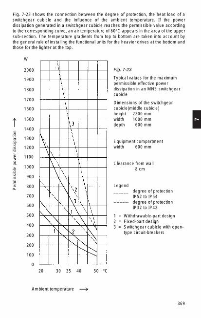
7
369
Fig. 7-23 shows the connection between the degree of protection, the heat load of aswitchgear cubicle and the influence of the ambient temperature. If the powerdissipation generated in a switchgear cubicle reaches the permissible value accordingto the corresponding curve, an air temperature of 60°C appears in the area of the uppersub-section. The temperature gradients from top to bottom are taken into account bythe general rule of installing the functional units for the heavier drives at the bottom andthose for the lighter at the top.
Ambient temperature
Fig. 7-23
Typical values for the maximumpermissible effective powerdissipation in an MNS switchgearcubicle
Dimensions of the switchgearcubicle(middle cubicle)height 2200 mmwidth 1000 mmdepth 600 mm
Equipment compartmentwidth 600 mm
Clearance from wall8 cm
Legend______ degree of protection
IP52 to IP54---------- degree of protection
IP32 to IP42
1 = Withdrawable-part design2 = Fixed-part design3 = Switchgear cubicle with open-
type circuit-breakers
2000
W
1900
1800
1700
1600
1500
1400
1300
1200
1100
1000
900
800
700
600
500
400
300
200
100
020 30 35 40 50 °C
Per
mis
sibl
e po
wer
dis
sipa
tion
370
7.3.2 Internal arc test
When developing switchgear assembly designs, the primary goal must be to avoidfaults that could result in internal arcing.
With this in mind, the design of the electrical and mechanical interlocking(withdrawable-part versus subsection) must be considered with respect towithdrawable-part design. Another important point is the requirement for highavailability. This means that even if accidental arcing does occur, the entire assemblyshould not fail and be damaged but at worst one section – or even better – only theaffected withdrawable part will be destroyed. In addition, if such a malfunction occurs,the operating staff should not be endangered.
The occurrence of internal arcing can be greatly restricted with suitable design, such aswith internal subdivision of a switchgear cubicle. The effects of accidental arcing can belimited primarily by reducing the duration of arcing.
This can be achieved with the aid of suitable sensors that will react to light, temperatureor pressure and trip the backup feeder circuit-breaker, in general the incoming feedercircuit-breaker. This will result in arcing periods of 40 to 80 ms. Three-pole shorting linksoperating in connection with the incoming feeder circuit-breaker will enable evenshorter arcing periods. Both methods have the disadvantage of leaving the entire low-voltage switchgear assembly without power when the incoming feeder circuit-breaker istripped, with the result that a large part of the system fails.
The better technical solution is to use suitable design measures to ensure that the arcquenches itself after a few milliseconds in the event of such a fault, so only the faultyfunctional unit will fail. The remainder of the substation will remain in operation. Thiscan be done by selecting suitable layout, configuration and material for the wallscomprising the internal subdivisions.
Testing the response of switchgear assemblies to internal arcing – specified for mediumvoltage assemblies already for many years by a test directive (Section 8.2.3) – is nowalso regulated for low-voltage assemblies. The new test directive is available asSupplement 2 to DIN EN 60439-1 (VDE 0660 Part 500) or as IEC 61641. The preferredarc duration in the test should be 100 ms. As a maximum, arcing times of up to 500 msshould be considered. The response of the switchgear assembly is assessed by thefollowing criteria:– Properly secured doors or barriers shall not open.– Parts that could cause a hazard shall not come loose.– Arcing must not burn any holes in freely accessible, external parts of the enclosure.– The vertically installed indicators (black cotton cloth = cretonne) must not ignite.– The protective-conductor function for the exposed conductive parts of the enclosure
must be retained.

7
371
7.3.3 Verification of the short-circuit current capability of busbar systems
The most certain way to verify the short-circuit current capability of the busbar systemsof a TTA or PTTA is to test them with the rated short-time withstand current. Thecompact design of the busbar supports would demand relatively complicated andextensive calculations. For this reason, it is recommended that the basic (standard)design of the busbar system be subjected to a type test, ensuring that the TTA is testedfor the standard rated currents and standard rated short-circuit withstand current.Special solutions and interim values can then be very easily considered by resorting toan extrapolation procedure in accordance with DIN IEC 61117 (VDE 0660 Part 509).This technical report describes an extrapolation procedure for determining the short-circuit current capability of non type-tested busbar systems (NTS), derived from type-tested busbar systems (TS).
7.3.4 Calculation programs for planning and design of low-voltage substations
Many companies offer calculation programs for the PC for planners. DOC by ABB –Version 020C – is described here as an example. It is designed for IBM-compatiblecomputers. The program is supplied on 3.5" diskettes. They contain the individualprogram modules, the database and the texts in compressed and encrypted form. Theprogram is currently available in seven languages (German, English, Italian, French,Spanish, Portuguese, Danish).
The required operating system is MS-DOS/PC-DOS 5.0 or higher and code page 437is necessary. Version 020C was also developed for use in a local area network.
This version includes the following features:– Rating of cables of low-voltage systems– Thermal verification of conductors and busbars– Calculation of short-circuit currents– Examination of dynamic load on busbars and their supports– Selection of circuit-breakers– Starting of motors– Assignment of circuit-breakers and fuses, contactors and thermal relays– Assignment of circuit-breakers: selectivity and protective functions– Examination of outgoing feeder-cable protection– Calculation and drawing of time-current characteristics– Power factor correction– Selective assignment of protection equipment on the low-voltage and medium-
voltage side of transformers– Calculation of overtemperature in switchgear assemblies– Drawing of general circuit diagrams– Printing a summary of all completed project planning and engineering– Data output in special file formats for dialogue with the programs of CAD, CIM– Individually designed configuration based on the connected hardware (monitor,
printer, etc.), the referenced standards and the database of the devices in use
372
7.4 Rated voltage 690 V
Publications in the 1970s frequently referred to the technical and economic advantagesof a higher rated voltage. As early as 1967 IEC Publication 38 listed the voltage level of660 V as a preferred voltage in comparison to the 500 V level. Particularly in the areaof device development, great efforts were made to upgrade them generally for 660 V.Today it can be assumed that almost all switchgear is suitable for this voltage. Thehigher voltage has become firmly established in the power distribution sector, e.g. inpower plants, many industrial plants and for the power supply of high-output motorsinstead of 3 kV or 6 kV.
The supplementary benefits of the 690 V voltage level for the user is in many casesquite significant, but it needs to be evaluated with reference to the actualimplementation. In general, implementation of the 690 V offers the followingadvantages in comparison to 400 V (and with lower values in comparison to 500 V):– Reduction of the rated currents– Reduction of the short-circuit currents– Reduction of the conductor cross sections for current transmission by 1 to 3 times– Lower power losses– Larger cable limit length with reference to voltage drop– Use of motors of up to 630 kW, i.e. elimination of the 6 kV for this output– More economical usage of reactive current compensation modules by greater
reactive power at 690 V– Increase in transformer rated power to 3150 kVA– Operation of 400 V motors (delta) also for 690 V (star)
The 690 V rated voltage today has a fixed position in low-voltage engineering. It hasreached a share of as high as 15%. It will soon have replaced the 500 V levelcompletely.
7.5 Selected areas of application
7.5.1 Design of low-voltage substations to withstand induced vibrations
The highest demands for functional safety under the influence of induced vibrations areplaced on important switchgear assemblies in particularly stressed buildings or at sitessubject to seismic disturbances.
The verification and testing of low-voltage substations under these conditions coversthe following loading cases: >earthquake<, >explosive shock wave< and >aircraftimpact<. The verification targets are stability, integrity and functional safety of theswitchgear cubicles and functional units.
The loading case >earthquake< is a low frequency waveform, which may have an effectfor some seconds, thereby distinguishing it from the loading cases of >explosiveshockwave< and >aircraft impact<. Both of these loading cases are high-frequencysquare wave pulses; the oscillations are excited in the millisecond range. To ensure thatthe loading cases of >explosive shock wave< and >aircraft impact< are covered by theloading case of earthquake, the switchgear assemblies are installed in rooms equippedwith resilient floors. These resilient floors sit on suitable schock insulators. They absorbthe square wave pulse and balance the waveform of an earthquake. This enables alltypes of loads, both computed and experimental, to be treated equally. The verifications
7
373
for the supporting structures and base frames of the switchgear assemblies aregenerally calculated in accordance with the German nuclear KTA 2201 regulation.
7.5.2 Low-voltage substations in internal arc-proof design for offshoreapplications
Offshore systems place very high demands on the quality of the technical equipment,because the fixed or floating offshore drill rigs operate autonomously and technicalfailures can have serious consequences. Repeated faults and personal injuries makeparticular demands on the user. The low-voltage switchgear assemblies are alsoincluded in these demands, because they must continue to function under the severestweather conditions. In addition to the general basic conditions listed below, offshoresystems have stringent requirements for internal arc-proof design of the incomingfeeder, coupling feeder and also for the switchgear cubicles for the motor control centre(MCC) in withdrawable-part design.
Examples of the general conditions for substation design are listed below:– All plastic components must be halogen-free– Plastic support components for live parts must be designed to be creepage-proof in
accordance with CTI 300 and must have self-extinguishing properties– All steel parts must be galvanized– Substations must be delivered in accordance with IEC 60439-1– The requirements of IEC 60092 must be met– The busbars must be isolated– The switchgear cubicle must be subdivided into separate functional compartments
(busbar compartment, equipment compartment, cable terminal compartment)– The substation must have a minimum weight (busbar, e.g. Cu-Al)
The MNS system corresponds to these general requirements even in its standarddesign. ABB has supplied electrical equipment and components for more than1000 ships and offshore units. The request for internal arc-proof design has been takeninto account in separate tests. The results from the comprehensive tests confirm thesuitability of the equipment. The internal arc-proof capability of the MNS systems hasbeen successfully confirmed in the test. In addition to compliance with the test criteriaas specified in the regulations, the following results are important:– The internal arc self-extinguishes after 1.5 to 100 ms.– The effects of the internal arc remain restricted to the place where it occurred.– Neighbouring withdrawable parts remain fully functional.– Additional equipment enables incoming feeder cubicles to withstand a 50 kA internal
arc for 300 ms.– Additional tests were passed with 40 kA at 720 V.

374
7.5.3 Substations for shelter
Application approval certification is required for electrical equipment and assembliesintended for installation in shelters. This confirms that the requirements of the relevanttechnical directives for civil defence construction have been met and that approval forinstallation in a shelter has been granted. The inspecting authority requires theapplication approval certification as verification for all protection construction supportedby federal funding. The application approval certification is issued by the federal civildefence office (BZS, Bonn) on behalf of the federal ministry for regional planning,building and urban development (BMBAU, Bonn). The BZS is also responsible fortesting and verifying the shock safety of equipment installed in shelters. ABB has beenawarded the application approval certification for medium-voltage substations, low-voltage substations, INS switchboxes and various switchgear and installed material.
The shock test is conducted on factory-new test samples. The test centre specifies thescope of testing required and the details of the shock test, such as special rigging,number of test objects and testing schedule. Test centres are the German army provingground in Meppen and the federal office for civil defence experimental establishment atAhrbrück. The exact testing conditions are specified by the BMBAU and are describedin the appendix to the general basic construction standards for shelters, “Verification ofShock Safety of Installed Parts in Shelters”. There are specific control classes forclassifying the shock safety, which are defined by recording the main characteristics ofthe test. The main characteristics are the test parameters of velocity and accelerationof the shock polygon. For example, control class 0.63 / 6.3 refers to a test velocity of0.63 m/s at an acceleration of 6.3 g.
The shock safety is assessed with degrees of safety A, B and C.– A: unrestricted shock safety. This means that the installed part must be guaranteed to
retain unrestricted function even during the shock effect.– B: restricted shock safety. This means that the installed part function may only be
affected for the duration of the shock effect.– C: minimum safety. This means that only safety against subsequent damage in the
personal and technical environment of the installed parts must be guaranteed.
The INS, KNS and MNS low-voltage substation systems have been subjected to shocktesting and have passed the test. The BMBAU has issued an application approvalcertification for the substations. The certifications are valid for operation in civil sheltersup to and including control class RK 0.63/6.3, degree of safety B. Only the wall plugsapproved for civil defence shall be used for securing the switchgear cubicles to thebuilding.

8
375
The blades of knife-contact disconnectors installed in an upright or hanging positionmust be prevented from moving by their own weight.
Disconnectors can be actuated manually and, in remotely operated installations, bymotor or compressed-air drives.
8.1.2 Switch-disconnectors
Switch-disconnectors are increasingly being used in distribution networks for switchingcables and overhead lines. Switch-disconnectors in connection with HV fuses are usedfor protection of smaller transformers.
Switch-disconnectors are switches that in their open position meet the conditionsspecified for isolating distances. General purpose switches can make and break alltypes of operating currents in fault-free operation and in the event of earth fault. Theycan also make and conduct short-circuit currents.
8. Switchgear and switchgear installationsfor high voltage up to and including 52 kV(medium voltage)
8.1 Switchgear apparatus (≤ 52 kv)
This voltage range is generally referred to as “medium voltage”, even though the termhas not been standardized anywhere.
The principal terms relating to switchgear are defined in Section 10.1.
8.1.1 Disconnectors
The classic design of the disconnector is the knife-contact disconnector (Fig. 8-1). Ithas become less common with the increasing use of withdrawable circuit-breakers andswitch-disconnectors. This functional principle is now again becoming more frequent ingas-insulated switchboard technology.
Fig. 8-1Medium-voltage knife-contactdisconnectors
Fig. 8-2NAL type knife-contact switch-disconnector: a) without and b) with fuse assembly
a) b)

376
Knife-contact switch-disconnectors (Fig. 8-2) and rod-type switch-disconnectors (Fig.8-3) are actuated in two ways:
a) “Snap-action mechanism”, also referred to as toggle-spring mechanism. With thistype of operating mechanism, a spring is tensioned and released shortly before theoperating angle is completed and its release force actuates the main contact systems.This is used for both closing and opening.
b) “Stored-energy mechanism”. This mechanism has one spring for closing and asecond spring for opening. During the closing operation, the opening spring issimultaneously tensioned and latched. The stored energy for the opening operation isreleased by magnetic trips or the striker pin of the HV fuse.
The rod-type switch-disconnector is particularly suitable for the design of compactswitchbays, because the knife-contact switch-disconnector requires a greater depth forthe switching zone because of the projecting contact blade in its open state. The rod-type switch-disconnectors also enable very small phase spacings without phasebarriers.
8.1.3 Earthing switches
Earthing switches are installed in switchbays primarily near cable boxes, i. e. before themain switching device. However, earthing switches are often specified also for busbarearthing, for example in metering panels. If the main switching device is a switch-disconnector, the earthing switch and the switch-disconnector will often be on acommon base frame (Fig. 8-4).
Fig. 8-3C4 rod-type switch-disconnector: a) without and b) with fuse assembly
Fig. 8-4Configuration ofearthing switches onthe switch-disconnector baseframe
a) b)
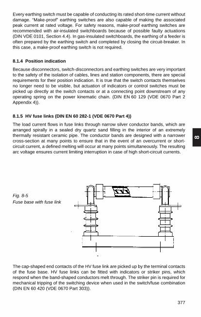
8
377
Fig. 8-5Fuse base with fuse link
Every earthing switch must be capable of conducting its rated short-time current withoutdamage. “Make-proof” earthing switches are also capable of making the associatedpeak current at rated voltage. For safety reasons, make-proof earthing switches arerecommended with air-insulated switchboards because of possible faulty actuations(DIN VDE 0101, Section 4.4). In gas-insulated switchboards, the earthing of a feeder isoften prepared by the earthing switch and completed by closing the circuit-breaker. Inthis case, a make-proof earthing switch is not required.
8.1.4 Position indication
Because disconnectors, switch-disconnectors and earthing switches are very importantto the safety of the isolation of cables, lines and station components, there are specialrequirements for their position indication. It is true that the switch contacts themselvesno longer need to be visible, but actuation of indicators or control switches must bepicked up directly at the switch contacts or at a connecting point downstream of anyoperating spring on the power kinematic chain. (DIN EN 60 129 (VDE 0670 Part 2Appendix 4)).
8.1.5 HV fuse links (DIN EN 60 282-1 (VDE 0670 Part 4))
The load current flows in fuse links through narrow silver conductor bands, which arearranged spirally in a sealed dry quartz sand filling in the interior of an extremelythermally resistant ceramic pipe. The conductor bands are designed with a narrowercross-section at many points to ensure that in the event of an overcurrent or short-circuit current, a defined melting will occur at many points simultaneously. The resultingarc voltage ensures current limiting interruption in case of high short-circuit currents.
The cap-shaped end contacts of the HV fuse link are picked up by the terminal contactsof the fuse base. HV fuse links can be fitted with indicators or striker pins, whichrespond when the band-shaped conductors melt through. The striker pin is required formechanical tripping of the switching device when used in the switch/fuse combination(DIN EN 60 420 (VDE 0670 Part 303)).

378
Characteristic current values for HV fuse links:Rated currentThe majority of fuse links in operation have a rated current ≤ 100 A. For specialapplications with smaller service voltages (e.g. 12 kV), fuse links up to 315 A areavailable. The associated melt-through times of the fusible conductors are found fromthe melting characteristics (manufacturer information for the range of the interruptingcurrents) (Fig. 8-6).
Rated breaking currentThis value must be provided by the manufacturer of the fuse link. It is influenced by thedesign for a specified rated current. When selecting fuse links for transformer protectionin distribution systems, the maximum breaking current is not a critical quantity.
Rated minimum breaking currentClassification of fuse links into three categories
– Back-up fusesSmallest breaking current (manufacturer information) in general at 2.5 to 3.5 timesrated current. Suited for application in switch/fuse combinations. Very common!
– General purpose fusesThe minimum breaking current is that which results in melt-thRough after 1 hour ormore of exposure time (generally twice the rated current).
– Full-range fusesEvery current that results in a melt-through can be interrupted.
Cut-off current characteristicThe maximum value of the current let-through by the fuse depends on its rated currentand the prospective short-circuit current of the system. Fig. 8-7 shows a characteristicfield.
Fig. 8-6The melting time depending on theovercurrent/short-circuit current
Fig. 8-7The cut-off current depending on theprospective short-circuit current
Symmetrical short-circuit current kA (eff.)
Max
. cut
-off
curr
ent k
A (
peak
val
ue)
Current in A
Mel
ting
time
Min
utes
Sec
onds

8
379
Selecting fuse links for specific conditionsWhen protecting transformers (Table 8-1) and capacitors with fuses, the inrush currentsmust be taken into account. When protecting transformers, selectivity by making themelting times match of low-voltage fuses and HV fuses is required to ensure that thelow-voltage fuses respond first. This is taken into consideration in Table 8-1.
Table 8-1
Approved protection of transformers on the medium-voltage side (fuse-links type CEF)and on the low-voltage side.1)
Rated transformer output (kVA)
50 75 100 125 160 200 250 315 400 500 630 800 1000 1250 1600 2000 2500
High-voltage fuses In (A)
3 25 25 40 40 63 63 63 80 100 100 160 200 200 2502)3152)
5 16 25 25 25 40 40 63 63 63 80 100 100 160 200 200 2502)3152)
6 16 16 25 25 25 40 40 63 63 63 80 100 100 160 200 2002502)
10 10 16 16 16 25 25 25 40 40 63 63 63 80 100 100 160 20012 10 16 16 16 16 25 25 25 40 40 63 63 80 100 100 160 16015 10 10 16 16 16 16 25 25 25 40 40 63 63 63 100 100 12520 10 10 10 16 16 16 16 25 25 25 40 40 63 63 63 80 10024 10 10 10 10 16 16 16 16 25 25 25 40 40 63 63 63 8030 10 10 10 10 10 16 16 16 16 25 25 25 40 40 40 2x40 2x4036 10 10 10 10 10 10 16 16 16 16 25 25 25 40 40 2x40 2x40
Rated Low-voltage fuses In (A)voltage (V)
220 80 100 125 160 200 250 250 315 400 500 630380 50 63 100 100 125 125 200 250 250 350 400 400 500 630500 40 50 80 80 100 100 160 160 200 250 350 350 400 500 630
1) Maximum rated current of the low-voltage protection that yields selectivity with the high-voltagefuse.
2) CMF-type fuse link
Ratedvoltage(kV)
In capacitor banks the rated current of the HV fuse links should be at least 1.6 times therated current of the capacitors. Experience has demonstrated that this covers also theinfluences of possible system harmonics and increased voltage.
When selecting fuse links for protection of high-voltage motors, the starting current andthe starting time of the motors must be taken into account. The frequency of startupsmust also not be neglected if this is frequent enough to prevent the fuses from coolingdown between starts.

380
8.1.6 Is-limiter – fastest switching device in the world
The increasing requirements for energy throughout the world demand higher rated orsupplementary transformers and generators and tighter integration of the supplysystems. This can also result in the permissible short-circuit currents of the equipmentbeing exceeded and the equipment being dynamically or thermally destroyed.
It is often not technically possible or not economical for the user to replaceswitchboards and cable connections with new equipment with increased short-circuitcurrent capability. The implementation of Is-limiters when expanding existinginstallations and constructing new installations reduces short-circuit currents and costs.
A circuit-breaker does not provide protection against impermissibly high peak short-circuit currents, because it is too slow. Only the Is-limiter is capable of detecting andlimiting a short-circuit current in the initial rise, i.e. in less than one millisecond. Themaximum instantaneous current value that occurs remains well below the peak valueof the short-circuit current of the system.
Typical Is-limiter applications (Fig. 8-10):
– in couplings,– in coupling the public system with a private supply,– parallel to reactor coils,
(avoids copper losses and voltage drop at the reactor coils)– in transformer or generator feeders,– in outgoing feeders.
The Is-limiter is a current-limiting switching device, which detects and limits the short-cicuit current in the initial rise. The short-cicuit current through the Is-limiter is limited soquickly that it does not contribute in any way to the peak value of the short-cicuit currentat the fault site.
t
63 kA
i2
i1
126 kAi
i = i1 + i2
(25 kA x χχ x 2) i = i1 + i2
o
m
i1
i = i1 + i2
i2
IK = 25 kA IK = 25 kA
IK zul. = 25 kA
T1 T2
χ
Fig. 8-8Short-circuit breaking with Is limitersa) Current path
io Total current without Is limiter im Total current with Is limiter
b) Basic layout
a) b)

8
381
In principle, the Is-limiter consists of an extremely fast switching device that can conducta high rated current, but has a low switching capacity and a parallel configured fuse withhigh breaking capacity. To achieve the desired short switching delay, a small charge isused as energy storage for opening the switching device (main current path). Once themain current path has been opened, the current still flows through the parallel fuse,where it is limited within 0.5 ms and then is finally interrupted in the next voltage zero.
1 4
5
2
3
Fig. 8-9Holder and insert of an Is-limiter
1 Insulating tube2 Charge3 Bursting bridge (main current path)4 Fuse5 Insulator with pulse transformer
Table 8-2
Rated voltages and currents for Is-limiter
Rated voltage Rated current kV A
0.75 .... 4.500
12.0 .... 4.000
17.5 .... 4.000
24.0 .... 2.500
36.0 (40.5) .... 2.500
Is-limiter inserts are parallel connected for higher currents
The Is-limiter is from all points of view the ideal switching device for solving short-circuitproblems in switchboards in power plants, in heavy industry and for power supplycompanies.

382
8.1.7 Circuit-breakers
There are still a number of “small-oil-volume” circuit-breakers in use for rated voltagesto 52 kV in systems, but for new installations only vacuum or SF6 circuit-breakers areused.
Circuit-breakers can be fix-mounted or integrated into the switchbay with appropriateinterlocking mechanisms in withdrawable unit design.
Circuit-breakers must be capable of making and breaking all short-circuit and servicecurrents occurring at the operational site. See 10.4.3 for details. The testing conditionsfor the corresponding verifications can be found in DIN VDE 0670 Part 102 and Part 104.
Vacuum circuit-breakers
Vacuum circuit-breakers of the VD4 type are available from the ABB Calor Emagproduction range for short-circuit breaking currents up to 63 kA with rated currents from400 to 3150 A. The VD4 range covers the voltage ranges of 12 kV, 17.5 kV, 24 kV and36/40 kV.
Fig. 8-11 shows a vacuum circuit-breaker of the VD4 type in column design.
a) b) c)
T1 T2G
Fig. 8-10
The most common applications for Is-limiters are:a) couplings, b) in power supplies, c) parallel to reactors in power supplies and inoutgoing feeders.
Fig. 8-11
Section through breaker type VD4 1 Upper connection2 Vacuum interrupter3 Lower connection4 Contact pressure spring5 Insulated coupling rod6 Opening spring7 Spring stored-energy operating mechanism

8
383
The components of the main circuit are covered by tubular epoxy resin insulators. TheVD4 circuit-breaker is therefore particularly suitable for use with compact switchbays ofsmall dimensions.
Fig. 8-12 shows the VD4 circuit-breaker with isolating contact arms on the withdrawablemodule frame for use in air-insulated switchboards, e.g. of type ZS1.
Fig. 8-12
VD4 circuit-breaker for 12 kVas a withdrawable unit
Fig. 8-13
Vacuum interrupter in sectional view,simplified overview
1 Insulator2 Fixed contact3 Movable contact4 Metal bellows5 Shielding6 Contact stem7 Cover8 Protection guide9 Central shield
Fig. 8-12 shows the most important components of a vacuum interrupter of the ABBrange in sectional view. All joints of the conducting path and of the enclosure aremanufactured by brazing in vacuum furnaces with inserted brazing material rings. Thisresults in an extremely reliable and long-lasting seal.
The contacts are a copper/chrome compound material, a copper base containingevenly distributed fine-grained chrome particles, which has a good extinguishing andarc-resistant response when switching short-circuit currents, and is also distinguishedby low-chopping current values when breaking small currents.
1
2
9
3
4
5
6
7
8

384
Switching overvoltages
Switching overvoltages when switching inductive loads with vacuum circuit-breakershave long been a subject of discussion. The introduction of copper/chrome as contactmaterial has significantly reduced the occurence of hazardous overvoltage values. Tocover the residual risk, surge arresters based on metal oxide (MO) are recommendedfor specified applications. Examples of such applications are:– small motors (with starting current below about 600 A),– small generators,– reactor coils for power factor compensation,– dry-type transformers in industrial application.
Only in special cases (e.g. furnace transformers) are supplementary RC circuitsrequired, preferably in the form of ZO-R-C combinations (zinc oxide+R+C).
Actuating systems
The travel of movable contacts between open and closed position in the vacuum circuit-breaker is between 8 and 14 mm depending on the rated voltage. At the end of theclosing stroke, the energy for tensioning the contact pressure springs is required. Therelatively low total energy requirement for vacuum circuit-breakers is generally providedby mechanical spring stored energy operating mechanisms, as with the VD4 type.Tripping is initiated by magnetic trips or manually. The mechanical operatingmechanism of the VD4 circuit-breaker is always suitable for autoreclosing (0 – t – CO).
Fig. 8-14 shows a new actuating system for the VM1 type circuit-breaker. The movablecontacts here are actuated by a permanent magnet mechanism with two stable endstops. The contact movements are initiated by current pulses (approx. 100 Watt / 45 ms), generated by discharge of a capacitor with a charged voltage of 80V, i.e. with less tripping energy than with magnetic trips of the mechanicalmechanism.
1 Upper connection2 Vacuum interrupter3 Epoxy resin enclosure4 Lower connection5 Flexible connector6 Contact pressure spring7 Insulated coupling rod8 Lever shaft9 Stroke setting
10 Sensors for position indication11 ON coil12 Permanent magnets13 Magnet armature14 OFF coil15 Manual emergency trip16 Actuator housing
Fig. 8-14Vacuum circuit-breaker VM1 (dimensions fully compatible to type VD4)
1
2
3
4
5
6
7
16
15
14
13
12
11
10
8 9
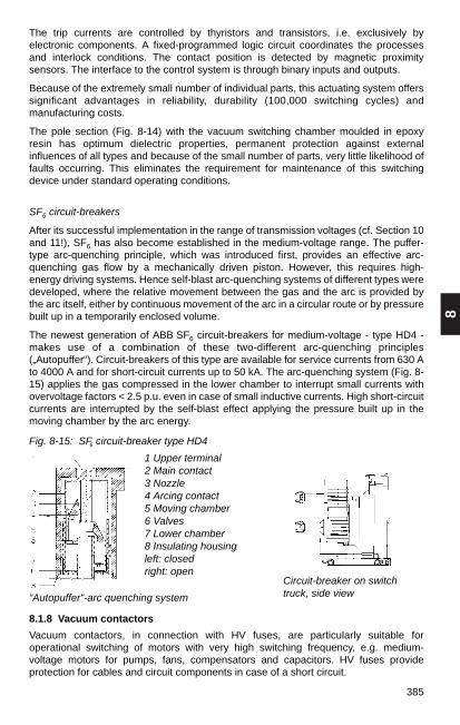
8
385
The trip currents are controlled by thyristors and transistors, i.e. exclusively byelectronic components. A fixed-programmed logic circuit coordinates the processesand interlock conditions. The contact position is detected by magnetic proximitysensors. The interface to the control system is through binary inputs and outputs.
Because of the extremely small number of individual parts, this actuating system offerssignificant advantages in reliability, durability (100,000 switching cycles) andmanufacturing costs.
The pole section (Fig. 8-14) with the vacuum switching chamber moulded in epoxyresin has optimum dielectric properties, permanent protection against externalinfluences of all types and because of the small number of parts, very little likelihood offaults occurring. This eliminates the requirement for maintenance of this switchingdevice under standard operating conditions.
SF6 circuit-breakers
After its successful implementation in the range of transmission voltages (cf. Section 10and 11!), SF6 has also become established in the medium-voltage range. The puffer-type arc-quenching principle, which was introduced first, provides an effective arc-quenching gas flow by a mechanically driven piston. However, this requires high-energy driving systems. Hence self-blast arc-quenching systems of different types weredeveloped, where the relative movement between the gas and the arc is provided bythe arc itself, either by continuous movement of the arc in a circular route or by pressurebuilt up in a temporarily enclosed volume.
The newest generation of ABB SF6 circuit-breakers for medium-voltage - type HD4 -makes use of a combination of these two-different arc-quenching principles(„Autopuffer“). Circuit-breakers of this type are available for service currents from 630 Ato 4000 A and for short-circuit currents up to 50 kA. The arc-quenching system (Fig. 8-15) applies the gas compressed in the lower chamber to interrupt small currents withovervoltage factors < 2.5 p.u. even in case of small inductive currents. High short-circuitcurrents are interrupted by the self-blast effect applying the pressure built up in themoving chamber by the arc energy.
Fig. 8-15: SF6 circuit-breaker type HD4
8.1.8 Vacuum contactors
Vacuum contactors, in connection with HV fuses, are particularly suitable foroperational switching of motors with very high switching frequency, e.g. medium-voltage motors for pumps, fans, compensators and capacitors. HV fuses provideprotection for cables and circuit components in case of a short circuit.
1 Upper terminal2 Main contact3 Nozzle4 Arcing contact5 Moving chamber6 Valves7 Lower chamber8 Insulating housingleft: closedright: open
“Autopuffer“-arc quenching system
Circuit-breaker on switch truck, side view

386
Vacuum contactors have a life expectancy (electrical) of 1•106 switching cycles, andcan handle a switching frequency up to 1200 on/off operations per hour. The V-contacttype vacuum contactors (Fig. 8-16) have the performance data listed in Table 8-3.However, the table does not note whether suitable fuses are available to takeadvantage of the listed performance ranges.
Rated voltage kV 3,6 7.2 12Rated current A 400 400 400
Suited for– Motors of up to kW 1 500 3 000 5 000– Capacitors of up to kVAr 1 500 3 000 4 800
Fig. 8-16
Vacuum contactor, type V-Contact
a) front view a) section view
1 connection terminals 2 vacuum interrupter 3 contactor coil 4 auxiliary contacts
Table 8-3
Performance data of type V-contact vacuum contactors
8.2 Switchgear installations (≤ 52 kv)
8.2.1 Specifications covering HV switchgear installations
This voltage range – generally referred to as medium voltage – covers switchbays inuse and on the market that can be classified as per one of the two followingspecifications:
DIN VDE 0101 orDIN EN 60298 (VDE 0670 Part 6)
8.2.2 Switchgear as per DIN VDE 0101
Switchgear installations as per DIN VDE 0101 are designed to comply with fixedminimum clearances of live components from one another, from earth potential andfrom protecting barriers. They can basically be manufactured at the site where they willbe operated. Current-carrying capacity for service and short-circuit currents must beverified by calculation (cf. Section 4. also). Type testing is not required.
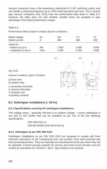
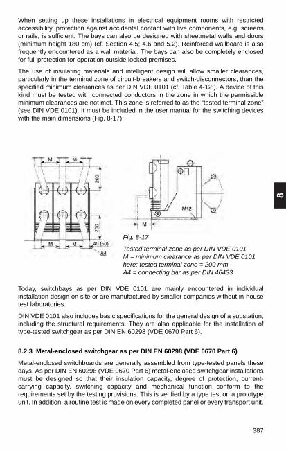
8
387
When setting up these installations in electrical equipment rooms with restrictedaccessibility, protection against accidental contact with live components, e.g. screensor rails, is sufficient. The bays can also be designed with sheetmetal walls and doors(minimum height 180 cm) (cf. Section 4.5; 4.6 and 5.2). Reinforced wallboard is alsofrequently encountered as a wall material. The bays can also be completely enclosedfor full protection for operation outside locked premises.
The use of insulating materials and intelligent design will allow smaller clearances,particularly in the terminal zone of circuit-breakers and switch-disconnectors, than thespecified minimum clearances as per DIN VDE 0101 (cf. Table 4-12:). A device of thiskind must be tested with connected conductors in the zone in which the permissibleminimum clearances are not met. This zone is referred to as the “tested terminal zone”(see DIN VDE 0101). It must be included in the user manual for the switching deviceswith the main dimensions (Fig. 8-17).
Fig. 8-17
Tested terminal zone as per DIN VDE 0101 M = minimum clearance as per DIN VDE 0101here: tested terminal zone = 200 mmA4 = connecting bar as per DIN 46433
Today, switchbays as per DIN VDE 0101 are mainly encountered in individualinstallation design on site or are manufactured by smaller companies without in-housetest laboratories.
DIN VDE 0101 also includes basic specifications for the general design of a substation,including the structural requirements. They are also applicable for the installation oftype-tested switchgear as per DIN EN 60298 (VDE 0670 Part 6).
8.2.3 Metal-enclosed switchgear as per DIN EN 60298 (VDE 0670 Part 6)
Metal-enclosed switchboards are generally assembled from type-tested panels thesedays. As per DIN EN 60298 (VDE 0670 Part 6) metal-enclosed switchgear installationsmust be designed so that their insulation capacity, degree of protection, current-carrying capacity, switching capacity and mechanical function conform to therequirements set by the testing provisions. This is verified by a type test on a prototypeunit. In addition, a routine test is made on every completed panel or every transport unit.
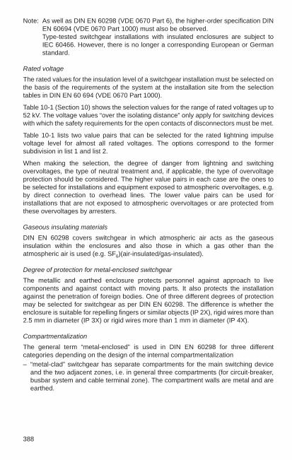
388
Note: As well as DIN EN 60298 (VDE 0670 Part 6), the higher-order specification DINEN 60694 (VDE 0670 Part 1000) must also be observed.Type-tested switchgear installations with insulated enclosures are subject to IEC 60466. However, there is no longer a corresponding European or Germanstandard.
Rated voltage
The rated values for the insulation level of a switchgear installation must be selected onthe basis of the requirements of the system at the installation site from the selectiontables in DIN EN 60 694 (VDE 0670 Part 1000).
Table 10-1 (Section 10) shows the selection values for the range of rated voltages up to 52 kV. The voltage values “over the isolating distance” only apply for switching deviceswith which the safety requirements for the open contacts of disconnectors must be met.
Table 10-1 lists two value pairs that can be selected for the rated lightning impulsevoltage level for almost all rated voltages. The options correspond to the formersubdivision in list 1 and list 2.
When making the selection, the degree of danger from lightning and switchingovervoltages, the type of neutral treatment and, if applicable, the type of overvoltageprotection should be considered. The higher value pairs in each case are the ones tobe selected for installations and equipment exposed to atmospheric overvoltages, e.g.by direct connection to overhead lines. The lower value pairs can be used forinstallations that are not exposed to atmospheric overvoltages or are protected fromthese overvoltages by arresters.
Gaseous insulating materials
DIN EN 60298 covers switchgear in which atmospheric air acts as the gaseousinsulation within the enclosures and also those in which a gas other than theatmospheric air is used (e.g. SF6)(air-insulated/gas-insulated).
Degree of protection for metal-enclosed switchgear
The metallic and earthed enclosure protects personnel against approach to livecomponents and against contact with moving parts. It also protects the installationagainst the penetration of foreign bodies. One of three different degrees of protectionmay be selected for switchgear as per DIN EN 60298. The difference is whether theenclosure is suitable for repelling fingers or similar objects (IP 2X), rigid wires more than2.5 mm in diameter (IP 3X) or rigid wires more than 1 mm in diameter (IP 4X).
Compartmentalization
The general term “metal-enclosed” is used in DIN EN 60298 for three differentcategories depending on the design of the internal compartmentalization– “metal-clad” switchgear has separate compartments for the main switching device
and the two adjacent zones, i.e. in general three compartments (for circuit-breaker,busbar system and cable terminal zone). The compartment walls are metal and areearthed.

8
389
– “compartmented” switchgear has the same degree of bay subdivision as “metal-clad”switchgear, but the compartment walls are of insulating material.
– “cubicle” switchgear is defined as all switchgear whose compartmentalization doesnot meet the requirements of the two above categories (e.g. only two compartments),but this also includes all switchgear that does not have internalcompartmentalization.
The decision on which of these installation categories is to be used in any specific caseis up to the user, with most attention paid to safety of personnel during maintenanceand cable work inside the switchbay. Restricting the effects of faults is important onlywhen the resistance of the compartment walls to arcing has been verified and when thecompartmentalization forms a true potential separation.
Internal arcing
All specialists are in basic agreement that manufacturers and users must make everyeffort to prevent under all circumstances faults in switchgear installations in whichinternal arcing occurs. However, it is also acknowledged that such faults cannot becompletely prevented in all cases. For this reason, it is expected that current switchgeardesigns have been tested for response to internal arcing.
Internal short-circuit arcs during operation can occur by overvoltage, faulty insulation orimproper control. The test consists of inducing the arc with an ignition wire connectedover all three phases. The arc has temperatures of around 4000 K in the area of itsfooting points and around 10 000 K or more in the area of the arc column. Immediatelyafter the arc has been ignited, the gas in in the immediate vicinity of the arc heats upinstantly, causing a very steep rise in pressure in the compartment concerned. Thispressure increase would continue to the load limit of the enclosure if pressure reliefvents were not built into it. The sealing covers or membranes of these vents respond inca. 5 to 15 ms and open the path to allow the heated gases to vent (Fig. 8-18). Thischaracteristic process is not determined only by the response time of the pressure reliefvalves but it also results from the mechanical inertia of the heated gas mass.
The maximum pressure reached is dependent on the volume of the compartmentwhere the fault occurs and on the magnitude of the short-circuit current. The greatestquantity of heated gases is given off into the area around the switchboard during theexpansion phase. The pressure stress on the panel exceeds its high point as early asabout 15 ms, that of the building has reached its maximum stress after 40 ms at thelatest. A powerful ejection of still heated gases of low density and glowing particlesoccurs in the subsequent emission phase and in the thermal phase.
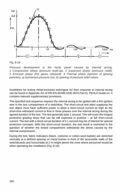
390
Fig. 8-18
Pressure development in the faulty panel caused by internal arcing, 1 Compression phase (pressure build-up), 2 Expansion phase (pressure relief), 3 Emission phase (hot gases released), 4 Thermal phase (ejection of glowingparticles). a) isochorous pressure rise, b) opening of pressure relief valves.
Guidelines for testing metal-enclosed switchgear for their response to internal arcingcan be found in Appendix AA of DIN EN 60298 (VDE 0670 Part 6). PEHLA Guide no. 4contains relevant supplementary provisions.
The specified test sequence requires the internal arcing to be ignited with a thin ignitionwire in the test compartment of a switchbay. The short-circuit test plant supplying thetest object must have sufficient power to allow a short-circuit current as high as theshort-time withstand current to flow in three phases over the internal arcing during theagreed duration of the test. The test generally lasts 1 second. This will cover the longestprotection grading times that can be still expected in practice – at full short-circuitcurrent. The test with a short-circuit duration of 0.1 second may be of interest for specialprotection concepts. With this short-circuit duration, the test result is restricted to thequestion of whether the tested compartment withstands the stress caused by theinternal overpressure.
During the test, fabric indicators (black, cretonne or cotton-wool batiste) are stretchedvertically at a defined spacing on metal frames in front of the accessible walls of theswitchboards and horizontally at 2 m height above the zone where personnel would bewhen operating the installation (Fig. 8-19).

8
391
After the short-circuit test, the test engineer records the response of the switchbay(s)tested based on six criteria. The following points are recorded:1. doors and screens have not opened,2. no hazardous parts were ejected,3. arcing did not cause any holes,4. none of the vertical fabric indicators in front of walls and doors ignited,5. none of the horizontal fabric indicators at a height of 2 m above the control zone
ignited,6. all earth connections are still effective.
High-speed film or video cameras can also provide additional information on whatoccurs during the test. They are therefore strongly recommended.
The test objects are not assessed with “pass/fail”. This allows the user to approveswitchbays for one application, even though a positive observation was not registeredfor every one of the above criteria.
This freedom to interpret the results is particularly significant with reference to criteria 4and 5, because in the event of ejection of hot gases, the switchbay itself is not primarilyrelevant for the effects. Reflection from the ceilings and walls in the emission phase andthe thermal phase (Fig. 8-18) can divert the hot gases coming from the pressure reliefvents into zones accessible for personnel and cause hazardous conditions there. Thehighest degree of damage also occurs during this period inside the switchbay. Theejection of very hot gas reaches its most hazardous amount under the condition whencaused by the direction of supply (from below) the electromagnetic forces compel thearc to persist in the immediate vicinity of the pressure relief vent. A switchbay type maybe considered fully tested only after this case has been considered.
Fig. 8-19
Test structure: thermal effects
a) Front view; b) Side view; 1 Discharge plate; 2 Horizontal indicators at 2.0 m height;3 Vertical indicators at distance A from test object; A = 300 mm for electrical equipmentrooms with restricted accessibility; A = 100 mm for generally accessible rooms.

392
Countermeasures for protection of personnel against these effects can be as simple asinstalling screens or discharge plates. At high short-circuit currents, hotgas conduitswith blow-out facilities using absorbers discharging into the switchgear installation roomare the perfect solution. However, even better results without additional installationscan be achieved if it is possible to limit the arc duration to approximately 100 ms byappropriate trip times. Because the grading times of the system protection do notgenerally allow such a short-term tripping of the feeder circuit-breaker, additionalsensors are required, such as the Ith-limiter. When one of the pressure relief valvesopens and there is simultaneous persistent short-circuit current, it initiates anundelayed trip command to the feeder circuit-breaker. This quenches the internal arc inless then 100 ms.
The pressure load on walls, ceilings, doors and windows of the switchgear installationroom is the result of the gas ejection during the expansion phase (Fig. 8-18). Thewithstand can generally not be verified by testing. All major manufacturers providecalculation programs for determining the pressure development in the switchgearinstallation compartment to find out whether pressure relief vents are required for theinstallation room.
8.2.4 Metal-enclosed air-insulated switchgear as per DIN EN 60298 (VDE 0670 Part 6)
Switchgear of this design have the largest market share throughout the world.
Metal-clad switchgear
Fig. 8-20 shows an example of metal-enclosed and metal-clad switchgear of type ZS1.
Fig. 8-20
Type ZS1 switchbgearA busbar compartment; B main switchingdevice compartment; C cable terminalcompartment; D low-voltage compartment;1 busbar; 2 isolating contacts; 3 circuit-breaker; 4 earthing switch; 5 current transformer; 6 voltage transformer
The circuit-breaker of this type of switchgear can be moved when the door is closedbetween the operating position and test position. Because vacuum circuit-breakersunder normal operating conditions are maintenance-free, the door to the circuit-breakercompartment can remain permanently closed. However, if it should be necessary toremove the switch from the switchbay, this can be done without problems on a servicetruck that can be adjusted for height to the exact position.

8
393
Access to the cable boxes can be made much easier by removing the circuit-breakerand also removing the partition between compartments B and C.
Compartment C has room for the cable boxes of several parallel cables. Metallic oxidearresters for overvoltage protection of inductive consumers can also be installed here.
When the circuit-breaker is in test position and the switchbay doors are closed, thecables can be earthed via the permanently installed earthing switch (with short-circuitmaking capacity). In order to check that the cables are dead voltage indicator plugs canbe inserted into test sockets at the front of the switchboards. The test sockets areconnected to the terminals of capacitive deviders, which are integrated into the currenttransformer.
Instead of the vacuum circuit-breaker, an SF6 circuit-breaker of the HD4 type withidentical main dimensions can be installed in this switchgear type.
The ZS-1 switchgear shown in Fig. 8-20 is available with the technical data and baydimensions shown in Table 8-4.
Table 8-4
Technical limit data and associated minimum bay dimensions of the ZS1 metal-enclosed metal-clad switchgear design series
Rated voltage kV 12 17.5 24
Rated short-duration power-frequency withstand voltage kV 28 38 50
Rated lightning impulse withstand voltage kV 75 95 125
Rated current– of the busbars A ... 4 000 ... 4 000 ... 4 000– of the feeders A 1250/ ... 4 000 1250/ ... 4 000 1250/ ... 2 500
Rated short-timewithstand current (3 s) kA 31.5/... 50 25/... 40 ... 25/... 25
Minimum bay dimensions– width mm 650/1 000 650/1 000 800/1 000 – depth mm 1 300/1 350 1 300/1 350 1 500/1 500 – height mm 2 200 2 200 2 200
In addition to the standard switchgear panel with draw-out circuit-breaker, there arevariations for sectionaliers, metering panels and bays with permanently installedswitch-disconnectors for substation power supply transformers. Double busbarinstallations are designed in accordance with the two circuit-breaker methods in back-to-back or front-to-front configurations (Fig. 8-21).

394
Cubicle switchgear
Fig. 8-22 shows metal-enclosed cubicle switchgear of type ZS8. Below are switchbayswith permanently installed switch-disconnectors for switching cables and overheadlines and with HV fuses for protection of distribution transformers. The switch-disconnectors can be remote-controlled with the motor-operated mechanism. In thecircuit-breaker bays, the VD4 and VM1 vacuum circuit-breakers are withdrawable unitsthat can be moved when the panel door is closed.
Fig. 8-22
ZS8 metal-enclosedcubicle switchgear:
a) switch-disconnectorpanel
b) circuit-breaker panel
Fig. 8-21
Double busbar switchgear installation ZS1, switchbays in back-to-back configuration
a) b)

8
395
All bay types of the ZS8 design series can be queued up in spite of varying dimensions.The switch-disconnector bay can also be supplied in the same depth as the circuit-breaker bay. The most important dimensions of these bays and their rating data areshown in Table 8-5.Table 8-5
Technical limit data and associated minimum bay dimensions of the ZS8 cubicleswitchgear
Rated voltage kV 12 17.5 24
Rated short-duration power kV 28 38 50frequency withstand voltage
Rated lightning impulse kV 75 95 125withstand voltage
Rated current– of the busbars A ... 1 250 ... 1 250 ... 1 250– of the switch-disconnector feeders A ... 630 ... 630 ... 630– of the circuit-breaker feeders A ... 1 250 ... 1 250 ... 1 250
Rated short-time kA ... 25 ... 20 161)/... 25withstand current (3 s)
Minimum bay dimensions– width of switch-disconnector bay mm 600 650 600 – depth of switch-disconnector bay
without/with branch compartmentalization mm 600/1 200 1 000/– 800/1 200
– width of circuit-breaker bay mm 650 650 800– depth of circuit-breaker bay
without/with branch compartmentalization mm 1 000/1 200 1 000/1 200 1 200/1 200
– height mm 1 900 1 900 1 900
ZS8 switchbays are not subdivided by metallic earthed compartment walls, as requiredfor the “metal-clad” category. For this reason, they must be classified in the “cubicle”category.
ZS8 switchbays are equipped with earthing switches (with short-circuit makingcapacity) for feeder earthing. The earthing switches can only be closed when theswitch-disconnector is open or the circuit-breaker withdrawable unit is in isolatedposition. There is an insulating plate integrated in every switchbay, which slides into theopen break of the switch-disconnector or in front of the busbar-side slide-in contacts ofthe circuit-breaker compartment. This assures protection against accidental approachto live components during work in the bay, e.g. at the cable terminals. There are alsoZS8 panels with “tee-off partitions” (Fig. 8-23). These bays have earthed metallicpartition, which separate the busbar system from the areas of switching devices andcable terminals. The electric protection against approach to the slide-in contactsinstalled in epoxy resin spouts is provided by earthed metallic shutters that swings infront of the epoxy resin spouts in these bays. The panel doors can only be opened afterclosing the protection shutter in all ZS8 type switchgear.
1) switch-disconnector bay for 24 kV only up to 16 kA
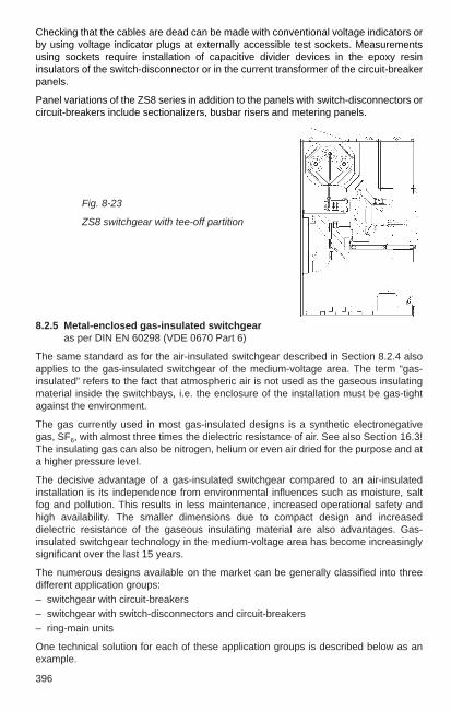
396
8.2.5 Metal-enclosed gas-insulated switchgear as per DIN EN 60298 (VDE 0670 Part 6)
The same standard as for the air-insulated switchgear described in Section 8.2.4 alsoapplies to the gas-insulated switchgear of the medium-voltage area. The term “gas-insulated” refers to the fact that atmospheric air is not used as the gaseous insulatingmaterial inside the switchbays, i.e. the enclosure of the installation must be gas-tightagainst the environment.
The gas currently used in most gas-insulated designs is a synthetic electronegativegas, SF6, with almost three times the dielectric resistance of air. See also Section 16.3!The insulating gas can also be nitrogen, helium or even air dried for the purpose and ata higher pressure level.
The decisive advantage of a gas-insulated switchgear compared to an air-insulatedinstallation is its independence from environmental influences such as moisture, saltfog and pollution. This results in less maintenance, increased operational safety andhigh availability. The smaller dimensions due to compact design and increaseddielectric resistance of the gaseous insulating material are also advantages. Gas-insulated switchgear technology in the medium-voltage area has become increasinglysignificant over the last 15 years.
The numerous designs available on the market can be generally classified into threedifferent application groups:– switchgear with circuit-breakers– switchgear with switch-disconnectors and circuit-breakers– ring-main units
One technical solution for each of these application groups is described below as anexample.
Fig. 8-23
ZS8 switchgear with tee-off partition
Checking that the cables are dead can be made with conventional voltage indicators orby using voltage indicator plugs at externally accessible test sockets. Measurementsusing sockets require installation of capacitive divider devices in the epoxy resininsulators of the switch-disconnector or in the current transformer of the circuit-breakerpanels.
Panel variations of the ZS8 series in addition to the panels with switch-disconnectors orcircuit-breakers include sectionalizers, busbar risers and metering panels.

8
397
Gas-insulated switchgear with circuit-breakers
Fig. 8-24 shows switchgear type ZX1 (for 12, 17.5 and 24 kV) with the versatile optionsoffered by the advanced technology of these new switchgear designs.
The principles used for the application are:
High-precision housing
– The gas-tight housing of the live components is manufactured of stainless steel usinglaser technology for high-precision cutting and welding. This not only ensures thatthe housing is gas-tight but also allows the bays to be queued up on site withoutproblems.
Fig. 8-24 Metal-enclosed gas-insulated switchgear type ZX1 withsingle busbar system1 Panel enclosure, complete2 Secondary compartment3 Cable terminal compartment4.1 Integrated pressure release
duct4.2 Pressure release duct, cable
terminal compartment4.3 Pressure relief flap5 Core module6 Circuit breaker pole7 Bay control and protection
unit REF5428 Pressure sensor9 Cable and test socket10 Cable socket11 Cable plug12 Surge arrester (as example)13 Pressure release plate14 Busbar15 Transfer switch15.1 Transfer switch mechanism16 Circuit-breaker mechanism17 Combined current/voltage
sensor with capacitive tap18 Main earthing conductor18.1 Bay/bay earthing
connection strap19 Bag of desiccating agent20 Base plate, divided
Insulation gas in core moduleand inside c.-b. pole tube
Vacuum switching technology
– The application of vacuum switching technology as the quenching principle of thecircuit-breaker meets a primary requirement for gas-insulated switchgear: theinterruptor unit must be maintenance-free. So far, this requirement is really only metby vacuum interrupters, because of their low contact wear and their high electricaldurability. Gas-insulated switchgear for this voltage range with SF6 circuit-breakers isalso available.
13
19
14
5
15
6
17
4.2
18
18.1
20
2
7
8
15.1
16
9
10
1112
3
4.14.3 1

398
Plug connector technology
– The application of plug-in technology is essential for ensuring short assembly timeswhen setting up installations. Several parallel cables can be connected to thecommercially available internal conical sockets in the baseplate of the core module.The plug-in technology in the area of the busbar bushings is new but based on thesame technology as the cable connectors. These bushings designed as plugconnectors are the most important requirement for easy installation of the completedpanels. There are additional plug connectors in the supply lines for auxiliary powerand in the fibre-optic connections to the higher-order control system, if present.
Sensors for measured quantities and states
– The combined current/voltage sensor has three functions. For current measurement,it has a Rogowski coil, which gives a voltage signal that has a linear dependency onthe current and therefore can be used in a very broad current range (e.g. to 1250 Ain one type). This not only simplifies planning but also increases the flexibility whenmodifying installations that are already operating.
– A high-resistance (200 MΩ) voltage divider is used as a voltage sensor. Two bell-shaped screening electrodes ensure equal distribution of the electric field along theresistance. The voltage signal captured at the subresistance of the devider is fed tothe bay control unit.
– The earth side of the two screening electrodes is simultaneously used as acapacitive tap to the voltage indicator plugs. It is connected with test sockets on thefront of the switchboard to allow checking that the cables are dead independently ofthe functional availability of the bay control unit.
– The positions of the two switching devices and the ‘ready for switching’ indication ofthe circuit-breaker mechanism are detected by inductive proximity sensors. Atemperature-compensated pressure sensor signals three pressure/density levels,i.e. fill pressure at 20°C, lower operational pressure limit and pressure with internalarcing. All sensor information goes directly to the bay control unit and is displayedand processed there.
Digital bay control and protection unit
– The digital REF542 bay control and protection unit is the base of the intelligence andcommunications interface of the new switchgear (see also Section 14!)
It has the following functions:
– – on site and remote actuation– – display of positions, measured values, protective parameters– – interlocking, internal and external– – protection (all protective functions except for cable differential protection)– – storage of events– – information transmission to a higher-order control system– – monitoring its own functions and the tripping circuits

8
399
– Faults in the sequence of actuation of circuit-breaker and disconnector/earth switchfunction of the transfer switch are prevented by interlocking in the REF542. Theearthing process can be automatically run by the REF542 as a programmedsequence while retaining the “five rules of safety”. Any required protective functionscan be programmed in as software before delivery. Software changes can be madeon site at any time with a laptop computer. Parameter changes can be made bypressing buttons on the device itself.
Personnel safety design– A switchgear design such as that of the ZX1 makes the occurrence of faults with
internal arcing unlikely from the start. However, the ZX1 offers complete personnelprotection in the event of internal arcing. In the case of a fault in the area of theinsulating gas, the housing is relieved from excessive stress by the response of thepressure release plate in the pressure release duct, which runs horizontally throughall bays and at the end of the installation releases the gas into the open air throughan outside wall or into the switchgear installation room via an absorber. Theresponse of the pressure sensor at 0.6 bar overpressure can be used to trip thefeeder circuit-breaker immediately without requiring additional components, therebyreducing the arcing time to less than 100 ms. In the event of a fault in the cableterminal area, the pressure is relieved through the back channel into the horizontalpressure release duct.
Double busbar switchgear installations can be designed with the panel type ZX1, inaccordance with the two-circuit-breaker method in back-to-back or front-to-frontarrangement. Bay variations such as sectionalizer, busbar riser and metering panel arealso available.
The most important rating data and the main dimensions of the ZX1 switchgear areshown in Table 8-6.
Table 8-6
Technical limit data and associated minimum panel dimensions of ZX1 type metal-enclosed gas-insulated switchgear
Rated voltage kV 12 17.5 24
Rated short-duration power-frequency withstand voltage kV 28 38 50
Rated lightningimpulse withstand voltage kV 75 95 125
Insulating gas – N2 SF6 SF6
Rated fill pressure, absolute bar 1.3 1.3 1.3
Rated current– of the busbars A ... 2000 ... 2 000 ... 2 000– of the feeders A 1 250/2 000 1 250/2 000 1 250/2 000
Rated short-timewithstand current (3 s) kA ... 40 25 25
Minimum panel dimensions– width mm 600/800 600/800 600/800 – depth mm 1 250/1 300 1 250/1 300 1 250/1 300 – height mm 1 950 1 950 1 950

400
As shown in Table 8-6, with 17.5 kV and 24 kV, SF6 is used as insulating gas while with12 kV nitrogen (N2) is used. Nitrogen has the advantage over air that it preventsoxidation of contact surfaces and lubricants.
The switchgear type ZX2 (Fig. 8-25) is suited for “conventional” double busbarsubstations that have two busbar systems for every switchbay. This switchgear has thesame advanced features as described for switchgear type ZX1.
Table 8-7 shows the technical data implemented to date with the associated maindimensions.
Table 8-7
Technical limit data and associated minimum panel dimensions of the ZX2 type metal-clad gas-insulated switchgear
Rated voltage kV 12 17.5 24 36
Rated short-time power-frequency withstand voltage kV 28 38 50 70
Rated lightning impulsewithstand voltage kV 75 95 125 170
Insulating gas – N2 SF6 SF6 SF6
Rated fill pressure, absolute bar 1.3 1.3 1.3 1.3
Rated current– of the busbars A ... 2 500 ... 2 500 ... 2 500 ... 2 500– of the feeds A 800/1250/...2500 1250/...2500
Rated short-timewithstand current (3 s) kA ... 40 ... 40 ... 40 ... 40
Minimum panel dimensions– width mm 400/600//800 600/800– depth mm 1 710 1 710 1 710 1 710 – height mm 2 300 2 300 2 300 2 300
Fig. 8-25 Metal-clad gas-insulated switchgearwith double busbar system type ZX2
1 Panel enclosure, complete2 Secondary compartment3 Cable terminal compartment4.1 Integrated pressure release duct4.2 Integrated pressure release duct5 Core module6 Circuit-breaker pole7 Bay control and protection unit REF5428 Pressure sensor9 Cable and test socket10 Cable socket11 Cable plug12 Surge arrester (as example)13 Pressure release plate14 Busbar systems Insulating gas
Single-busbar switchgear in the ZX2 design can also be manufactured without the rearbusbar system to make full use of the advanced technical data.
4.1
13
14
5
13
4.2
1
2
7
86
9
10
11123

8
401
Gas-insulated switchgear with switch-disconnectors and circuit-breakers
Gas-insulated switchgear technology is becoming the subject of increasing interest fordistribution systems and smaller industrial consumers. Because the high performancedata are not required as with the installations described in the previous section, specialswitchgear series have been developed for this application. A major characteristic ofthis application is the use of switch-disconnectors for feeders with cables and overheadlines and in combination with fuses for protection of smaller transformers.
Fig. 8-26 shows cross-sections through variations of the switchgear series ZX0. SF6 isused as insulating gas and quenching medium for the switch-disconnectors for all ratedvoltages.
The switch-disconnectors integrated into the panels include the function of the earthingswitch for the feeder as a combination device. The contact blades are actuated by thesame mechanism for one or the other function depending on the actuation direction.The combination device as switch-disconnector meets the same requirements as aswitch-disconnector tested and manufactured as a single unit as per DIN EN 60265-1(VDE 0670 Part 301). The requirements of DIN EN 60129 (VDE 0670 Part 2) apply forthe earthing function (with short-circuit current-making capacity).
Fig. 8-26
Metal-enclosed gas-insulated switchgear system type ZXO
a) circuit-breaker panel b) switch-disconnector panel c) switch-disconnector panelwith fuses
a) b) c)
In order to check that the cables are dead before earthing voltage indicator plugs canbe inserted into test sockets at the front of the switchboard. These sockets areconnected to the taps of field grading electrodes inside the cable-plug bushings.
The circuit-breaker bays of this type of switchgear have vacuum interrupters with aresin coating as arc-quenching systems. This also forms the pivot of the 3-position switch for disconnecting and earthing.

402
Table 8-8
Technical limit data and associated minimum panel dimensions of the ZX0 metal-enclosed gas-insulated switchgear system
Rated voltage kV 12 17.5 24
Rated short-duration power-frequency withstand voltage kV 28 38 50
Rated lightningimpulse withstand voltage kV 75 95 125
Insulating gas – SF6 SF6 SF6
Rated fill pressure, absolute bar 1.3 1.3 1.3
Rated current– of the busbars A 1 250 1 250 1 250– of the switch-disconnect. feeder A 800 800 800– of the switch-disconnect. feeder
with HV fuses A 200 100 100– of the circuit-breaker feeder A 630 630 630
Rated short-timewithstand current (3 s) kA ... 25 ... 20 ... 20
Panel dimensions– width mm 400 400 400 – depth mm 850 850 850 – height mm 16501)/19502) 16501)/19502) 16501)/19502)
Ring-main units for distribution systems
There are two basic designs in use for this purpose:– modular switchboards with the option of later expansions,– switchboards with a common gas volume inside a common enclosure with a preset
number (e.g. 3 or 4) of feeders.
Fig. 8-27 shows such a type CTC switchboard with common enclosure for all threefeeders.
1) For switchboards without circuit-breaker panels 2) For all panels of a switchboard with circuit-breaker panels
The connected cables are therefore earthed via the circuit-breakers. The REF542digital bay control and protection unit also controls the actuation, interlocking, displayand protection functions in the circuit-breaker panel of the switchgear system ZX0.
Table 8-8 shows limit data and dimensions of the ZX0 type switchgear system.

8
403
SF6 switch-disconnectors are also used here for switching the connected cables andoverhead lines. For protection of transformers, either a vacuum circuit-breaker withelectronic protection (type CTC-V, Fig. 8-27) or a switch-disconnector in combinationwith HV fuses (type CTC-F, same dimensions as CTC-V) can be supplied.
Every switchbay has an earthing switch with specified making capacity to earth theconnected cables. In order to check that the cables are dead before earthing voltageindicator plugs can be inserted into test sockets at the front of the switchboard. Thesesockets are connected to the taps of field grading electrodes inside the cable-plugbushings.
The switch-disconnectors and circuit-breakers of the switchboards can be remotelyactuated with motor-operated mechanisms. Table 8-9 shows limit data and dimensionsof the CTC gas-insulated ring-main unit.
Fig. 8-27
Front view a) and side view b) of the ring-main switchboardtype CTC.
Table 8-9
Technical limit data and dimensions of the CTC metal-enclosed gas-insulated ring-mainunit
Rated voltage kV 12 17.5 24
Rated short-duration power-frequency withstand voltage kV 28 38 50
Rated lightning impulse withstand voltage kV 75 95 125
Insulating gas – SF6 SF6 SF6
Rated fill pressure, absolute bar 1.4 1.4 1.4
Rated current– of the cable ring feeder A 630 400 400– of the transformer feeder
(CTC-F) A 200 100 100– of the transformer feeder A 630 400 400
Rated short-timewithstand current (3 s) kA 20 16 16
Switchboard dimensions– width mm 1 000 1 000 1 000 – depth mm 760 760 760 – height mm 1 500 1 500 1 500
a) b)

404
8.2.6 Control systems for medium-voltage substations
Conventional secondary technology
A wide range of devices for protection, control and monitoring tasks is available forconventional secondary technology in medium-voltage switchgear installations. Theplanning engineer selects the required single units and combines them into oneinstallation.
The information on measured values, switchgear status and interference messages istransmitted through parallel wiring from the various medium-voltage bays to a maincontrol desk or a telecontrol system. Records, data storage, graphical measured valueprocessing, help information when faults occur and self-monitoring functions are notpossible with this technology.
Microprocessor control systems
The implementation of digital system designed for the requirements of medium-voltagenetworks allows a number of much more powerful solutions at moderate expense. Asystem of this type is divided into the bay level, the switchboard level and the controlroom level (see also Section 14.4!).
At the bay level autonomously operating, modular and multifunction devices that can beadapted for the required protection, control and regulating tasks by appropriatesoftware are used. These monitoring devices are installed directly in the secondarycompartment of the medium voltage switchbays. Here, all measured values, switchpositions and messages from the bays are acquired, processed and sent over a serial(unified) interface. The device, which operates independently of the next hierarchylevel, combines the protective functions, the switching position display, the measuredvalue display and the local operation of the switchgear, which is protected against faultyoperation, in one single housing. Its modular design makes it adaptable for the bay-specific protection tasks and selectively or in combination controls functions such asmotor protection, overcurrent definite-time protection, over and undervoltageprotection, earth fault detection, distance protection, differential protection and alarmdescription. It has comprehensive self-monitoring functions and also allows events tobe sorted by time with real-time stamping.
The REF542 bay control and protection unit is a device of this type. It can optionally beimplemented autonomously for one switchbay only or integrated into a higher-orderautomation control system.

8
405
Fig. 8-28
Substation design with fully insulated cable link to the transformer, 1 transformermultiple terminal, 2 substation building, 3 switchboard, 4 cable plug, 5 cable link in protective conduit
8.3 Terminal connections for medium-voltage installations
8.3.1 Fully insulated transformer link with cables
Plastic-insulated cables and fully insulated (plug-in) cable terminals provide a numberof operational improvements in substation design when consistently used at theinterfaces between cables and station components. The key component for a new typeof cable link, Fig. 8-28, between the power transformer and the switchboard is amultiple transformer terminal, Fig. 8-29, for four parallel power cables. The multipleterminal is designed for a rated voltage of up to 36 kV and enables rated currents of upto 3150 A. It can be retrofitted to all power transformers. In addition to the operationaladvantages, this technology offers savings because the transformer no longer requiresa cable rack. For more information on plug connectors for power cables, see Section13.2.8.
Fig. 8-29
View a) and section b) of a transformer multiple terminal
1 Cable connector 2 Moulded resin body with sockets3 Metal housing4 Conductor bar5 Contact system6 Transformer housing7 Control shield
2
5
1
3
4

406
Fig. 8-30
Sectional view of an SF6-insulated busbar
1 Inner conductor 2 Outer tube3 Flange joint with insulator4 Internal expansion joint5 External expansion joint
(metal bellows)6 T-junction enclosure7 Cross-junction enclosure8 Cover with and without
connection9 Insulating flange
10 Outdoor bushing11 Conductor elbow joint12 Suspension13 Mounting flange 14 Current transformer
8.3.2 SF6-insulated busbar connection
The busbar shown below in Fig. 8-30 is designed for a rated voltage of up to 36 kV andrated currents of up to 3150 A.
The busbar system consists of several individual parts that can be combined to makeall required connections. It is suitable for combining busbars of different sections ofswitchboards and for making connections to power transformers. Use at 12 kV is alsopossible with the use of N2 as insulating gas.
8.3.3 Solid-insulated busbar connection
Another option for making busbar connections with low space requirements is to useepoxy-resin-insulated capacitor-controlled single-phase conductors. They are availablefor service voltage of up to 72.5 kV and for operating current of up to 5000 A.
Design of the busbar system
The preferred conductor material is an aluminium alloy with high mechanical strengthand low weight. The insulation (Fig. 8-31) is in direct contact with the conductors, withcapacitive control provided by conducting layers at the ends. The covering layer atearth potential is fully embedded in the insulation. For outdoor use the bars are alsoenclosed in a protective tube.

8
407
The bar section lengths are up to 12 m. Single or multiple bends are available asrequired made to fit the assembly and connection dimensions. The bars are connectedrigidly or flexibly to the devices with screw or plug-type joints. Individual lengths arejoined with an insulating cylinder. The recommended phase clearances, e.g.200–300 mm at 2500 A, correspond to the phase spacings of the switchgear. Standardsupport structures and clamps withstand the short-circuit forces. The earth connectionscomply with the relevant specifications.
Fig. 8-31
Design of the DURESCA bar for indoor oroutdoor use. 1 Indoor connection, 2 Conductor, 3 Insulation, 4 Busbartermination with standard creepage distance,5 Busbar termination with extended creepagedistance, 6 Earth potential layer, 7 Earthconnection, 8 Surface finish for indoors:without protective cover, optionally withprotective tube or corrugated pipe; for outdoors: with protective tube orcorrugated pipe, 9 Porcelain insulating cover,10 Outdoor connection

408

9
409
9 High-current switchgear9.1 Generator circuit-breaker
Generator circuit-breakers are switchgear in the high-current connection betweengenerator and generator transformer. The electrical requirements on generator circuit-breakers are higher in many respects than for breakers in the network. Theserequirements are specified in the (unique in the world) "IEEE" C37.013 standard indetail (ANSI). The following list summarizes the most important areas of application andthe advantages.
Functions Advantages
In specific cases there can be economic, operational and technical reasons forimplementing such breakers.
Isolate generator from stationservices infeed
Synchronization on the low voltage side ofthe main transformer
Disconnection of a fault in the maintransformer or in the station servicetransformer.
Disconnection of a fault in the generator
Disconnection of faults on the overheadlines from the power plant to the nexttransformer station or substation.
Implementation in nuclear power plants.
Implementation in pumped-storage powerstations.
Automation of the power plant.
Station services fed via main trans-former. No longer requires the formerlystandard starting transformers and theassociated switchgear components andchangeover facilities (see Fig. 9-1a).
Eliminates voltage transformers on theh.v. side of the main transformer.Possibility of connecting two generatorsvia two separate transformers or onethree-winding transformer to oneoverhead cable simplifies power-plantdesign (see Fig. 9-1).
Effects of faults much more restrictedthan with high-speed de-excitationbecause it trips in less than 60 ms.
Station services remain on the networkwithout interruption, resulting in higheravailability. Safe handling of loadimbalances.
HV circuit-breaker no longer required inpower plant if transformers or switch-gear installations are near power plant.
Significantly improved security ofuninterruptable station services supply.
Switching between pump and generatoroperation without problem.
Only 1 switching operation tosynchronize or disconnect the genera-tor, instead of 5-7 switching operationswhen synchronizing on the HV side,resulting in reduction of the danger ofswitching faults.

410
Fig. 9-1
Unit connections of power plantsa) Basic circuit diagram, b) and c) Large generators with part-load transformers, d) Pumped storage block, e) Hydro power plant;1 Generator, 2 Generator breaker, 2a 5-pole generator breaker for switchover betweenmotor and generator operation, 3 High-voltage circuit-breaker 4 Main transformer, 5 Station services transformer, 6 Starting transformer, 7 Starting motor
Fig. 9-1 shows examples of unit connections with generator circuit-breakers. Thevarious types show how these breakers ensure maximum possible availability of stationservices in the event of a fault for large units with several main and station transformers.
Conventional power plants and nuclear power plants with high unit capacity and specialrequirements for safety and availability are preferred areas of application for generatorcircuit-breakers.
The use of generator circuit-breakers must be considered in the early stages ofdesigning a power plant. The following requirements are important when designing thestructure:
a) Space required for breakerBreaker dimensions; phase spacing (note minimum clearances); transport; accessand space for maintenance. Expansion of air-pressure wave (DR-breaker type only).
b) Space required for auxiliariesCooling unit (5-10 m2, at higher rated currents)Control cubicle (2.5-5 m2)Air-compressor plant (10-30 m2)(DR-breaker type only).The auxiliaries must be in the immediate vicinity of the generator circuit-breaker.
c) Structural requirementsStable foundation (attend to reaction forces)Maintenance pit (under DR-breaker only)Lifting gear for installation and maintenance.

9
411
Today, generator circuit-breakers are not generally offered as single unit but as afunctional unit, which contains the current and voltage transformers required forgenerator and unit protection inside single-phase enclosures, with disconnectors,shorting links and earthing switches, and also start-up disconnectors, surge arrestersand protection capacitors.
Fig. 9-2
Single-line diagram of a generator circuit-breaker system1 Main transformer, 2 Station services transformer, 3 Current transformer, 4 Surgearrester, 5 Protection capacitor, 6 Voltage transformer with 1 or 2 secondary windings, 7 Earthing switch, motor-actuated, 8 Series disconnector, motor-actuated, 9 Short-circuit connection with clip for earth connection, 10 Circuit-breaker, 11 Starting circuit-switch, motor-actuated, 12 Generator, 13 Earth
9.1.1 Selection criteria for generator circuit-breakers
Apart from the rated voltage, the most important criteria are the rated current and therated breaking current of the power unit. ABB supplies several types of generator
circuit-breaker, which can be used depending on the unit capacity.They include the SF6 breakers of the HG and HE range, the DR typeair-blast breaker and the type VD4G vacuum breaker.
Fig. 9-3 Selection table for generator circuit-breakers
12 3 6 10 8 6 3 1
13 5 7 11 9 7 45 2
DR
HEC 3-8
HGC3
HGCS
VD4G VD4Gwithfan
1000
250
180
6350
25
101000 3400 4500 7500 30000 50000
Rated voltages (IEC)
VD4G: 17.5 kV HGCS: 17.5 kV HGC3: 17.5 kV HEC: 24 - 36 kV DR: 36 kV
Rated current (A)
Rat
ed b
reak
ing
cu
rren
t (k
A)
412
9.1.2 Generator circuit-breaker type ranges HG... and HE...(SF6 gas breaker)
These breaker systems are designed for generator capacities of 100-1000 MVA and –depending on the type – can be used for the voltage levels 17.5-36 kV.They are suitable for both indoor and outdoor installation.
The power-interruptor chambers of these breakers are filled with SF6 gas as thequenching and insulation material. The arc is interrupted with the proven ABB self-blasting principle: The arc that is generated when the contacts open heats the SF6 gas,increases the pressure and generates a stronger gas flow, which blasts the arc andextinguishes it.The rotating arc reduces the contact erosion.
The contacts, which carry current continuously, are placed separately from theinterrupting contacts, guaranteeing optimum current transfer at all times.
The voltage-carrying components are air-insulated against earth.The 3-pole design on a common base frame makes installation very simple. Specialfoundations are not required.
The power chambers are actuated by the proven ABB type AHMA spring mechanism.The energy storage capacity is rated for 2 switching cycles ON-OFF. Disconnector,earthing switch and start-up switch have electric motor-operated mechanisms. Theyare controlled in accordance with the current requirements in power plant design withconventional relay technology.
The modular design makes it possible to expand the generator circuit-breakers to verycompact functional systems with disconnectors, earth switches, transformers etc. (seeFigs. 9-2, 9-4). Production and testing of the complete system in factoy greatly reducesthe time and expense of assembly and testing at the construction site.
The service intervals, in compliance with the demands of modern power plant design,have been extended to 15 years operational life or 10,000 switching cycles(mechanical). The single-line breaker enclosure is welded to the busduct enclosure.The live parts are bolted to the high-current busduct conductor by way of flexible copperextension straps.

9
413
Table 9-1
Technical data for generator circuit-breakers type HG ... and HE ... (SF6 gas breaker)
Type designation kV HGCS HGC3 HEC3 HEC4 HEC5 HEC6 HEC7 HEC8 HGI2 HGI3 HEK3
Rated voltage as per IEEE/ANSI kV 15.8 15.8 27.5 27.5 27.5 27.5 27.5 27.5 15.8 15.8 24
Rated voltage as per IEC kV 17.5 17.5 24 24 24 24 36 36 17.5 17.5
Rated short-time power frequency withstand voltage50/60 Hz 1 min, against earth kV 50 50 60 60 60 60 80 80 50 50 80
over isolating distance 1) kV 55 55 70 70 70 70 88 88 – – –
Rated lightning impulse withstand voltage 1.2/50 µs against earth kV 110 110 125 125 125 125 150 150 110 110 150
over isolating distance 1) kV 121 121 145 145 145 145 165 165 – – –
Rated current,2) 3)
natural cooling, 50 Hz A 4,500 7, 500 12,000 13,000 12,000 13,000 24,000 – 6,300 8,000 11,000
Rated current,2) 3)
natural cooling, 60 Hz A 4, 500 7,300 11,500 12,500 11,500 12,500 24,000 – – – 11,000
Rated current,3)
with forced ventilation, at 50 +60 Hz A – – – 24,000 – 24,000 – 28,000 – – 16,500
Breaking current kA 50 63 100 100 120 120 160 160 50 63 100
Making current kA 138 173 300 300 360 360 440 440 138 170 300
1) Only valid for models with disconnector2) Rated current information corresponding to ambient temperature: max. 40 °C3) Temperature of the high-current bus ducts at the breaker terminals: conductor max. 90 °C; encapsulation max. 65 °C

Fig. 9-4
Generator circuit-breaker systems of the HGC (dimensions in parentheses) and HECrange – outline drawing1 Control cubicle, 2 Short-circuit connection with disconnector, 3 Voltage transformer,4 Surge arrester, 5 Cable feed to start-up feed, 6 Opening shutter panel to mechanismcompartment, 7 Toroidal-core current transformer, 8 Earthing switch, 9 High-currentterminal, 10 Series disconnector, 11 Capacitor, 12 SF6 circuit-breaker, 13 Disconnectorto start-up feed, 14 Inspection glass for visual position check, 15 Removable covers forbreaker encapsulation, N Variable phase clearance
414
Transformer side
Generator side

9
415
The HGCS generator circuit-breaker system has a different design from the othersystems of this range. It has a switchbay compartmented by phases with all apparatuspermanently installed. The circuit-breakers can be slid out.
The generator circuit-breaker of the HEK 3 type is particularly well suited for integrationinto encapsulated busbar systems when retrofitting existing installations. Thegenerator circuit-breakers of the HGI 2 and HGI 3 types are available when retrofittingopen indoor busbar systems.
9.1.3 Generator circuit-breaker type DR (air-blast breaker)
This breaker type is designed for very large unit capacities up to 2000 MVA and above.The type DR generator circuit-breaker is single-line metal-clad and can be directlyintegrated into the high-current bus ducts. Both the breaker encapsulation and thebreaker live parts are connected to the high-current bus ducts with flexible copperexpansion straps.
The cooling components are 100% redundant, so in the event of faults, they can beswitched immediately to the standby unit and the power plant can continue operating.
Fig. 9-5 HGCS generator circuit-breaker system/outline diagram*= Minimum clearances
Transformer side
Cen
tral
cub
icle
SF 6
-Gen
erat
or
circ
uit-
bre
aker
Typ
HG
2
Base frame
Generator side Transformer side
High-current
terminals
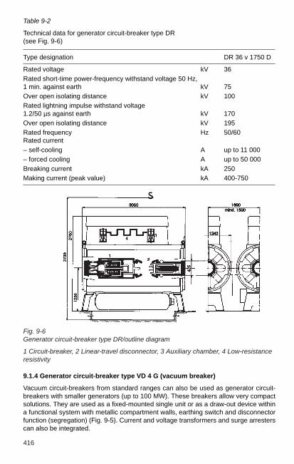
416
Fig. 9-6Generator circuit-breaker type DR/outline diagram
1 Circuit-breaker, 2 Linear-travel disconnector, 3 Auxiliary chamber, 4 Low-resistanceresistivity
Table 9-2
Technical data for generator circuit-breaker type DR(see Fig. 9-6)
Type designation DR 36 v 1750 D
Rated voltage kV 36Rated short-time power-frequency withstand voltage 50 Hz,1 min. against earth kV 75Over open isolating distance kV 100Rated lightning impulse withstand voltage 1.2/50 µs against earth kV 170Over open isolating distance kV 195Rated frequency Hz 50/60 Rated current– self-cooling A up to 11 000– forced cooling A up to 50 000Breaking current kA 250Making current (peak value) kA 400-750
9.1.4 Generator circuit-breaker type VD 4 G (vacuum breaker)
Vacuum circuit-breakers from standard ranges can also be used as generator circuit-breakers with smaller generators (up to 100 MW). These breakers allow very compactsolutions. They are used as a fixed-mounted single unit or as a draw-out device withina functional system with metallic compartment walls, earthing switch and disconnectorfunction (segregation) (Fig. 9-5). Current and voltage transformers and surge arresterscan also be integrated.
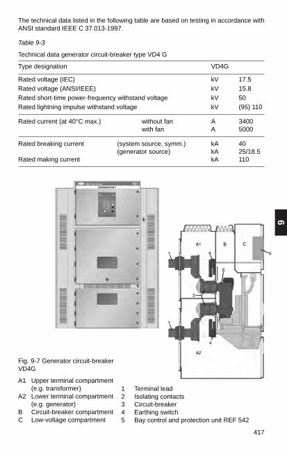
9
417
Fig. 9-7 Generator circuit-breakerVD4G
A1 Upper terminal compartment(e.g. transformer)
A2 Lower terminal compartment(e.g. generator)
B Circuit-breaker compartmentC Low-voltage compartment
1 Terminal lead2 Isolating contacts3 Circuit-breaker4 Earthing switch5 Bay control and protection unit REF 542
Table 9-3
Technical data generator circuit-breaker type VD4 G
Type designation VD4G
Rated voltage (IEC) kV 17.5Rated voltage (ANSI/IEEE) kV 15.8Rated short-time power-frequency withstand voltage kV 50Rated lightning impulse withstand voltage kV (95) 110
Rated current (at 40°C max.) without fan A 3400with fan A 5000
Rated breaking current (system source, symm.) kA 40 (generator source) kA 25/18.5
Rated making current kA 110
The technical data listed in the following table are based on testing in accordance withANSI standard IEEE C 37.013-1997.

418
9.2 High-current bus ducts (generator bus ducts)
9.2.1 General requirements
The high-current bus ducts with all their branches are a component of the electricalinstallation in the power plant.
The high-current bus duct and switchgear generally serve the following functions (Fig.9-8). – Connection between generator and main transformer(s) including generator neutral.
– Branch connections to station services and excitation transformers as well as voltagetransformer cubicles.
– Design and connection of measuring, signalling and protection devices for current,voltage and other operating data.
– Installation and connection of high-current switching devices such as generatorcircuit-breakers with high-current disconnectors and earth disconnectors.
– Additional facilities, e.g. for protection and working earthing, pressure-retainingsystems or forced cooling.
Fig. 9-8 High-current switchgear installation
1 High-current bus duct, 2 Generator, 3 Generator neutral point, 4 Neutral earthingcubicle, 5 Short-circuiting facility (temporary), 6 Voltage transformer cubicle, 7Excitation transformer, 8 Generator circuit-breaker, HEC type with 8.1 control cubicle,9 Voltage and capacitor cubicle, 10 Expansion joint, 11 Station auxiliary transformer,Main transformer, 14 Current transformer / feeder side, 15 Current transformer/neutralside
Note: The voltage transformers (6 and 9), the capacitors (9), the earth switch, theshort-circuiting facility (5) and the surge arrester (12) can also be installed in thegenerator terminals. The configuration of the current transformers (14) must be specified: a) at thegenerator feed, b) in the busbar run or c) in the generator circuit-breaker, to enablethe short-circuiting facility to be located at the proper position. Consultation with the supplier of the generator circuit-breaker is required.

9
419
Technical requirements
The design of the largest generators with nominal voltages of up to 27 kV and power upto 1600 MVA yields operating currents of up to 36 kA. For the high-current bus duct, thismeans that the generated heat in conductors and enclosure and the significantmagnetic field effects in the installation and its environment must be controlled.With the stated unit capacities and the high network outputs, short-circuit currents of upto approximately 750 kA peak value may occur in the high-current bus ducts and high-current switchgear. In the branches, peak short-circuit currents of more than 1000 kAmay occur. And of course the safety and availability of a high-current bus duct mustcorrespond with the high standard of the other power-plant components.The high-current bus ducts must therefore comply with specified requirements: – Adherence to preset temperature limits, – Adequate short-circuit current carrying capability, (thermal and mechanical strength
with short-circuits),– Adequate magnetic shielding,– Safe insulation, i.e. protection against overvoltages, moisture and pollution.
9.2.2 Types, features, system selectionTypesIn smaller power plants (hydropower, CHP stations) with a load current of up toapproximately 2.5 kA (5 kA), the bus ducts can still have the "classic" busbar design.The simplest designs are flat and U-shaped busbars of Al or Cu (sometimes alsotubular conductors, in Al only). Exposed busbars are used with small generator ratingsonly because they require locked electrical equipment rooms. In contrast, laying thebusbars in a common rectangular aluminium duct provides protection against contactand pollution. Aluminium partitions between the phases provide additional protection.This prevents direct short-circuits between the phases. In the event of short-circuitcurrents flowing, the compartment walls reduce the short-circuit forces (shielding) oninsulators and busbars.Single-phase systems can be supplied in single-insulator or triple-insulator designs. The ABB standard is the single-phase system with the following variations: – up to 5.5 kA in single-insulator design (type HS 5500)– up to 40 kA in triple-insulator design (type HA)
FeaturesABB high-current bus ducts in single-phase enclosure. The single-phase enclosure is the most commonly supplied and the most technicallyadvanced model. The conductors and the concentrically arranged enclosure aroundthe conductor consist of aluminium tubes and are insulated from each other by an airgap and resin insulators (Fig. 9-9)
Fig. 9-9 ABB high-current bus duct
a) Single-phase design withthree insulators
b) Single-phase design withone insulator
a) b)
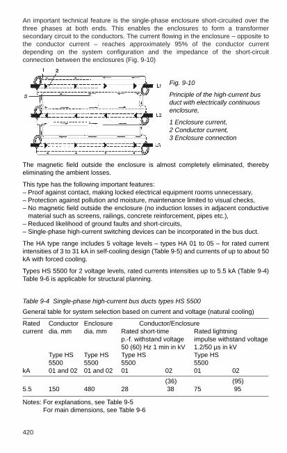
420
An important technical feature is the single-phase enclosure short-circuited over thethree phases at both ends. This enables the enclosures to form a transformersecondary circuit to the conductors. The current flowing in the enclosure – opposite tothe conductor current – reaches approximately 95% of the conductor currentdepending on the system configuration and the impedance of the short-circuitconnection between the enclosures (Fig. 9-10)
Fig. 9-10
Principle of the high-current busduct with electrically continuousenclosure,
1 Enclosure current,2 Conductor current,3 Enclosure connection
The magnetic field outside the enclosure is almost completely eliminated, therebyeliminating the ambient losses.
This type has the following important features:– Proof against contact, making locked electrical equipment rooms unnecessary, – Protection against pollution and moisture, maintenance limited to visual checks,– No magnetic field outside the enclosure (no induction losses in adjacent conductive
material such as screens, railings, concrete reinforcement, pipes etc.),– Reduced likelihood of ground faults and short-circuits, – Single-phase high-current switching devices can be incorporated in the bus duct.
The HA type range includes 5 voltage levels – types HA 01 to 05 – for rated currentintensities of 3 to 31 kA in self-cooling design (Table 9-5) and currents of up to about 50kA with forced cooling.
Types HS 5500 for 2 voltage levels, rated currents intensities up to 5.5 kA (Table 9-4)Table 9-6 is applicable for structural planning.
Table 9-4 Single-phase high-current bus ducts types HS 5500
General table for system selection based on current and voltage (natural cooling)
Rated Conductor Enclosure Conductor/Enclosure current dia. mm dia. mm Rated short-time Rated lightning
p.-f. withstand voltage impulse withstand voltage50 (60) Hz 1 min in kV 1.2/50 µs in kV
Type HS Type HS Type HS Type HS5500 5500 5500 5500
kA 01 and 02 01 and 02 01 02 01 02
(36) (95)5.5 150 480 28 38 75 95
Notes: For explanations, see Table 9-5For main dimensions, see Table 9-6

9
421
Table 9-5 Single-phase high-current bus ducts type HA
General table for system selection based on current and voltage (natural cooling)
Rated Conductor Enclosure Conductor/enclosurecurrent mm mm Rated short-time p.-f. withstand Rated lightning impulse withstand
voltage 50 (60) Hz 1 min in kV voltage 1.2/50 ms, in kV
Type HA Type HA Type HA Type HAkA 01 to 05 01 02 03 04 05 01 02 03 04 05 01 02 03 04 05
3 100 460 460 550 640 7305 190 550 550 640 730 8208 280 640 640 730 820 91010 370 730 730 820 910 1 000 (36) (60) (80) (80) (95) (110) (150) (150)12 460 820 820 910 1 000 1 090 28 38 50 70 70 75 95 125 145 17015 550 — 910 1 000 1 090 1 18017 640 — 1 000 1 090 1 180 1 27020 730 — 1 090 1 180 1 270 1 36022 820 — — 1 270 1 360 1 45024 910 — — 1 360 1 450 1 54026 1 000 — — 1 450 1 540 1 63030 1 000 — — — — 1 720
Note: test voltages as per DIN EN 60071-1 (VDE 0111, Part 1), Table 2; IEC 600 71-1, Table 2;( ) values in parentheses according to ANSI C 37.23.A cooling system is required for currents over 31 kA.
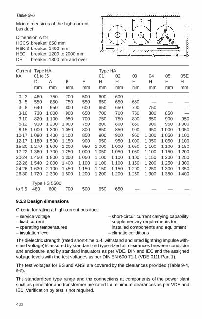
422
Table 9-6
Main dimensions of the high-current bus duct
Dimension A forHGCS breaker: 650 mm HEK 3 breaker: 1400 mmHEC breaker: 1200 to 2000 mm DR breaker: 1800 mm and over
Current Type HA Type HAkA 01 to 05 01 02 03 04 05 05E
D A B E H H H H H Hmm mm mm mm mm mm mm mm mm mm
0- 3 460 750 700 500 600 600 — — — —3- 5 550 850 750 550 650 650 650 — — —3- 8 640 950 800 600 650 650 700 750 — —3-10 730 1 000 900 650 700 700 750 800 850 —3-10 820 1 100 950 700 750 750 800 850 900 9505-12 910 1 200 1 000 750 800 800 850 900 950 1 0008-15 1 000 1 300 1 050 800 850 850 900 950 1 000 1 050
10-17 1 090 1 400 1 100 850 900 900 950 1 000 1 050 1 10012-17 1 180 1 500 1 150 900 950 950 1 000 1 050 1 050 1 10015-20 1 270 1 600 1 200 950 1 000 1 000 1 050 1 100 1 100 1 15017-22 1 360 1 700 1 250 1 000 1 050 1 050 1 050 1 100 1 150 1 20020-24 1 450 1 800 1 300 1 050 1 100 1 100 1 100 1 150 1 200 1 25022-26 1 540 2 000 1 400 1 100 1 100 1 100 1 150 1 200 1 250 1 30024-26 1 630 2 100 1 450 1 150 1 150 1 150 1 200 1 250 1 300 1 35026-30 1 720 2 300 1 500 1 200 1 200 1 200 1 250 1 300 1 350 1 400
Type HS 5500 to 5.5 480 600 700 500 650 650 — — — —
9.2.3 Design dimensions
Criteria for rating a high-current bus duct:– service voltage – short-circuit current carrying capability – load current – supplementary requirements for – operating temperatures installed components and equipment– insulation level – climatic conditions
The dielectric strength (rated short-time p.-f. withstand and rated lightning impulse with-stand voltage) is assured by standardized type-sized air clearances between conductorand enclosure, and by standard insulators as per VDE, DIN and IEC and the assignedvoltage levels with the test voltages as per DIN EN 600 71-1 (VDE 0111 Part 1).
The test voltages for BS and ANSI are covered by the clearances provided (Table 9-4,9-5).
The standardized type range and the connections at components of the power plantsuch as generator and transformer are rated for minimum clearances as per VDE andIEC. Verification by test is not required.

9
423
Computers are used for optimum and economical design of sizes and wall thicknessesfor conductor and enclosure on the basis of a comprehensive heat network; with full orpartial ventilation of the bus duct, this program is also used to design the coolingsystem. The standard rating is based on maximum limit temperatures with an ambienttemperature of 40°C:
Enclosure 65 °C – 80 °C; conductor 90 °C – 105 °C.
These values comply with all corresponding VDE, IEC and ANSI standards.
The short-circuit current carrying capability of the bus duct includes adequate provisionfor peak short-circuit and short-time current. Only one short-circuit current – either fromthe generator or from the system side – can occur on the main conductor, but in thebranches, the sum of the two short-circuit currents must be taken into account. Thesingle-phase enclosure design reduces the likelihood of a short-circuit by many times.
The main duct design for the rated current inevitably has a short-circuit current carryingcapability by that far exceeds the rated value dynamically and thermally.
However, the branch ducts are dimensioned primarily for peak and short-time currentwithstand in compliance with the ABB short-circuit calculations and the requirements ofthe relevant standards (Section 3 and 4). This automatically ensures compliance withthe permissible temperatures at load current.
9.2.4 Structural design
Conductors and enclosure are of Al 99.5% sheet (DIN 40501), which is rolled andsubmerged-arc welded. Conductors of up to 370 mm diameter are used in the form ofextruded aluminium tubes only. To improve thermal dissipation, the conductors arepainted on the outside and the enclosures inside and outside.
The prefabricated assemblies have a maximum length of about 12 m. The lengthdepends on the feasibility of transport and the access and installation conditions on theconstruction site.
Each support of the conductor consists of one or three post insulators – in exceptionalcases of four –, which are mounted from outside. Sliding surfaces or fixed pins on allinsulators of each support and a spring arrangement on one insulator per support allowrelative axial movements between the conductor and the enclosure.
The single-insulator system has been designed to carry currents in the range of 3 to 5.5 kA with the greatest possible safety with the compact design requiring the smallestpossible space. The single-insulator system offers all the advantages of single-phaseenclosed bus ducts (three-insulator system). In addition, the use of one freelyaccessible post insulator around the enclosure makes the assembly easier in verysmall spaces.
Post insulators and holder ring are manufactured from moulded resin and providesupport for the conductor and retain the air gap between conductor and enclosure.
The enclosure supports are independent of the support of the conductor and aredesigned as sliding or fixed-point, fastened directly to the support structure. The tubeprofile allows distances of enclosure supports of 10-20 m depending on the system.
All connections to the generator, to transformers and switchgear not only ensure secureelectrical connection but also allow adjustment, accommodation of thermal movementsand access to the junction points. The enclosure structure is particularly important atthe generator terminals because of the small spaces between them. In small andmedium-sized installations, three-phase terminal and neutral compartments with

424
hatches and viewing windows allow inspection and access to the connections. Athigher rated currents, only the single-phase enclosed bus duct construction providessufficient magnetic field compensation, prevents eddy currents and therefore ensurescontrolled temperature conditions.
The conductors are connected to the generator, transformers and switchgear terminalswith flexible press-welded copper straps fastened with bolts. Spring washers with highspring travel and force guarantee the required contact pressure and preventunacceptable temperature rise. The contact surfaces are silver-coated if required bythe conductor limit temperature (IEC and ANSI).
Current transformers for measurement and protection of the toroidal core type areeither installed at the generator terminal bushings or integrated into the bus duct at asuitable point. Detachable connections are then to be integrated into the mainconductor for installation and removal. Voltage transformers can be incorporated intothe bus duct or installed in separate instrument cubicles connected by branch ducts.The same applies for protection capacitors for limiting capacitively transmitted voltages.
Surge arresters protect bus duct and generator, even in the event of flashover in thetransformer, but are then usually overstressed. The use of housings with pressure reliefwill ensure the safety of personnel and the installation.
9.2.5 Earthing system
The design of earthing systems for high-current bus ducts is based on VDE 0141 andmore recently VDE 0101, which also comply with the other national and internationalstandards (such as IEC, ANSI, BS). The maximum anticipated double ground-faultcurrent can be calculated as follows:
3I"K EE = –— · I"K 32
The minimum cross section AE for the main earthing conductor as per VDE 0103 iscalculated as follows:
I"K EE · 103 · m + nAE min. = ———————–————
1Sthn · —TK
The earthing system of the ABB high-current bus duct uses the enclosure of the threephases as the earthing conductor. The separate conductors are restricted toconnecting the enclosure to the earth terminals on the generator, the transformers andthe connection to the power plant earthing system. All components outside the busbarrun such as cubicles etc. are connected to the enclosure and so are earthed "by spurs".See Section 5.3 for additional information on earthing.
Note:
When installing generator circuit-breakers, the earth switch and the short-circuitingfacility are integrated into the generator circuit-breaker.For detailed information, see generator circuit-breakers in Section 9.1!

425
9
9.2.6 Air pressure/Cooling system
Operational reliability can be further improved by supplying the high-current bus ductwith filtered dry air. The resulting overpressure of 500 Pa (max. 2000 Pa) allows air inthe bus duct to pass from inside to outside only, preventing contamination. The dry airalso prevents the formation of condensation. The incoming air is drawn through areducing valve and a gas meter from the power plant compressed-air system with orwithout a dryer and water separator, or from a circuit-breaker compressor, see alsoSection 15.5 Compressed-air system.
Forced ventilation of the high-current bus duct at 31 to max. 50 kA is of the closed looptype with an air-water heat exchanger for cooling. The ABB cooling unit is installedunder the bus duct as close to the middle as possible. The air is blown into the outerphases by fans and diverted to the middle phase at the end by control dampers anddeionizing screens via a connecting duct, in which it flows back to the cooling unit attwice the speed. The closed circuit air-cooling system is 100% redundant, allowing thesystem to be switched to the standby fan and cooler immediately when necessary. If thecooling system fails, the availability of the high-current bus duct is still 50–70%,depending on the design. Fig. 9-11 shows the air flow diagram of a high-current busduct.
The limited space in the generator terminal area and the requirement to be able to workwith smaller dimensions may require cooling with a single-pass airflow below 31 kA.
Fig. 9-11
Cooling-air flow diagram for a high-current bus duct, 1 High-current bus duct, 2 Coolingunit with fans a; Standby fans b; Dampers on standby fan c; Cooler d and standbycooler e; 3 Damper valves for flow distribution, deionization screens, 4 Cooling watercirculation with motor-operated valves f for cooler and standby cooler (flow and return)with safety valves g; Vent and discharge valves h; 5 Make-up air with filter-dryerelement i; 6 Alternative to 5: Make-up air from the compressed air system via reducingvalve k and air meter I.

426

10
427
10 High-voltage apparatus
10.1 Definitions and electrical parameters for switchgear
Disconnectors are mechanical switching devices which provide an isolating distance inthe open position. They are capable to open or close a circuit if either a negligiblecurrent is switched or if there is no significant change in voltage between the terminalsof the poles. Currents can be carried for specified times under normal operatingconditions and under abnormal conditions (e.g. short circuit). Currents of negligiblequantity have values 0.5 A; examples are capacitive charging currents for bushings,busbars, connections, very short lengths of cable and currents of voltage transformers.
Isolating distances are gaps of specified dielectric strength in gases or liquids in theopen current paths of switching devices. They must comply with special conditions forthe protection of personnel and installations and their existence must be clearlyperceptible when the switching device is open.
Switches are mechanical switching devices, which not only make, carry and interruptcurrents under normal conditions in the network but also must carry for a specific timeand possibly make currents under specified abnormal conditions in the network (e.g.short circuit).
Switch disconnectors are switches which satisfy the requirements for an isolatingdistance specified for a disconnector in their open position.
Circuit-breakers are mechanical switching devices able to make, carry and interruptcurrents occurring in the circuit under normal conditions, and can make, carry for aspecified time and break currents occurring in the circuit (e.g. short circuit) underspecified abnormal conditions.
Earthing switches are mechanical switching devices for earthing and short-circuitingcircuits. They are capable of carrying currents for a specified time under abnormalconditions (e.g. short circuit). They are not required to carry normal operating currents.Earthing switches for transmission networks may also be required to make, carry andbreak induced currents (capacitive and inductive) under normal circuit conditions.Earthing switches with short circuit making capability shall be able to make the short-circuit current.
Fuses are switching devices that open the circuits in which they are installed by themelting of one or more parts specified and designed for the purpose of breaking thecurrent when it exceeds a given value for a sufficiently long period.
Auxiliary switches must be rated for a continuous current of at least 10 A and becapable to break the current of the control circuits. The manufacturer must providedetails. In the absence of such information, they must be capable of breaking at least 2A at 220 V d.c. at a minimum circuit time constant of 20 ms. The terminals and wiring inauxiliary circuits must be designed for at least 10 A continuous current. The auxiliaryswitches that are actuated in connection with the main contacts must be directlyactuated in both directions.

428
Electrical characteristics
(Peak) making current: peak value of the first major loop of the current in one pole of aswitching device during the transient period following the initiation of current during amaking operation.
Peak current: peak value of the first major loop of current during the transient periodfollowing initiation.
Breaking current: current in one pole of a switching device at the instant of initiation ofan arc during a breaking process.
Breaking capacity: value of the prospective breaking current that a circuit-breaker orload switch can break at a given voltage under prescribed conditions for application andperformance; e.g. overhead line (charging current) breaking capacity.
Short-line fault: short circuit on an overhead line at a short but not negligible distancefrom the terminals of the circuit-breaker.
Out of phase (making or breaking) capacity: making or breaking capacity for which thespecified conditions for use and behaviour include the loss or the lack of synchronismbetween the parts of an electrical system on either side of the circuit-breaker.
Applied voltage: voltage between the terminals of a circuit-breaker pole immediatelybefore making the current.
Recovery voltage: voltage occurring between the terminals of a circuit-breaker poleafter interruption of the current.
Opening time: interval of time between application of the auxiliary power to the openingrelease of a switching device and the separation of the contacts in all three poles.
Closing time: interval of time between application of the auxiliary power to the closingcircuit of a switching device and the contact touch in all poles.
Break time: interval of time between the beginning of the opening time of a switchingdevice and the end of the arcing time.
Make time: interval of time between application of the auxiliary power to the closingcuircuit of a switching device and the instant in which the current begins to flow in themain circuit.
Rated value: value of a characteristic quantity used to define the operating conditionsfor which a switching device is designed and built and which must be verified by themanufacturer.
Rated normal current: the current that the main circuit of a switching device cancontinuously carry under specified conditions for use and behaviour. See below forstandardized values.
Rated short-time withstand current: current that a switching device in closed positioncan carry during a specified short time under prescribed conditions for use andbehaviour. See below for standardized values.
Rated voltage: upper limit of the highest voltage of the network for which a switchingdevice is rated. See below for standardized values.

10
429
Additional rated values:rated withstand current, rated making current, rated short-circuit breaking capacity etc.
Standard value: rated value based on official specifications to be used for designing adevice.
Standardized rated voltages: 3.6; 7.2; 12; 17.5; 24; 36; 52; 72.5; 100; 123; 145; 170;245; 300; 362; 420; 550; 800 kV.
Standardized rated normal currents: 200; 250; 400; 500; 630; 800; 1000; 1250; 1600;2000; 2500; 3150; 4000; 5000; 6300 A.
Standardized rated short-time currents: 6.3; 8; 10; 12,5; 16; 20; 25; 31,5; 40; 50; 63;80; 100 kA.
Rated insulation level: standardized combination of the rated values for the lightningimpulse withstand voltage, the switching impulse withstand voltage (if applicable) andthe short-time power frequency withstand voltage assigned to a rated voltage. Asstandardized insulation level, only combinations of values from one and the same lineof Table 10-1 are valid.
Rated short-duration power frequency withstand voltage: rms value of the sinusoidala.c. voltage at operating frequency that the insulation of a device must withstand underthe specified test conditions for 1 minute.
Rated lightning impulse withstand voltage: peak value of the standard voltage surge1.2/50 µs that the insulation of a device must withstand.
Rated switching impulse withstand voltage: peak value of the unipolar standard voltagesurge 250/2500 µs which the insulation of a device with a rated voltage of 300 kV andabove must withstand.
Note:
For disconnectors and specific (asynchronous) circuit-breakers for rated voltages of300 kV and above, the isolating distances or breaker gaps are tested with combinedvoltage so that the power frequency test voltage (Table 10-1, peak values inparentheses) is applied at one terminal and the counterpolar test surge voltage(lightning or switching) occurs in the time range of the maximum voltage at the otherterminal. The test with combined voltage was originally known as the bias test.

430
Table 10-1
Standardized rated insulation level for disconnectors, switches, circuit-breakers andearthing switches according to DIN EN 60 694 (VDE 0670 Part 1000)
Rated short-duration power Rated frequency withstand voltage lightning impulse withstand voltage
kV (rms value) kV (peak value)
Phase to earth, Phase to earth,between the phases between the phases
and across Across the and across Across thethe open isolating distance of the open isolating distance
breaker gap breaker gap
1 2 3 4 5
3.6 10 12 20 2340 46
7.2 20 23 40 4660 70
12 28 32 60 7075 85
17.5 38 45 75 8595 110
24 50 60 95 110125 145
36 70 80 145 165170 195
52 95 110 250 290
72.5 140 160 325 375
100 150 175 380 440185 210 450 520
123 185 210 450 520
230 265 550 630
145 230 265 550 630
275 315 650 750
170 275 315 650 750
325 375 750 860
245 360 415 850 950395 460 950 1 050460 530 1 050 1 200
(continued)
Rated voltagekV (rms value)

10
431
Table 10-1 (continued)
Rated short-duration Rated Rated switching impulse withstand voltage power frequency withstand voltage lightning impulse withstand voltage kV (peak value)
kV (rms value) kV (peak value)
Phase to earth Across the open Phase to earth Across the open Phase to earth Between Across theand between breaker gap and between breaker gap and across the phases isolating distancethe phases and/or the phases and/or the open
isolating distance isolating distance breaker gap
1 2 3 4 5 6 7 8
300 380 435 950 950 (+ 170) 750 1 125 700 (+ 245)
1 050 1 050 (+ 170) 850 1 275
362 450 520 1 050 1 050 (+ 205) 850 1 275 800 (+ 295)
1 175 1 175 (+ 205) 950 1 425
420 520 610 1 300 1 300 (+ 240) 950 1 425 900 (+ 345)
1 425 1 425 (+ 240) 1 050 1 575
550 620 800 1 425 1 425 (+ 315) 1 050 1 680 900 (+ 450)
1 550 1 550 (+ 315) 1 175 1 760
800 830 1 150 1 800 1 800 (+ 455) 1 300 2 210 1 100 (+ 650)
2 100 2 100 (+ 455) 1 425 2 420
The values in parentheses are the peak values of the a.c. voltage applied to the opposite terminal.
Rated voltagekV (rms value)

432
10.2 Disconnectors and earthing switches
Disconnectors are used for galvanic isolation of networks or sections of switchgearinstallations. As an independent air-insulated device, they form a visible isolatingdistance in their open position. They are suitable for switching small currents (< 0.5 A)or also larger currents if the voltage does not change significantly between the contactsof a disconnector pole during switching (commutation currents).
Disconnectors can carry currents under operating conditions continuously and underabnormal conditions, such as short circuit, for a specified time (1s, 3s).
More than 10 different designs are in use around the world. The most important arerotary disconnectors, two-column vertical break disconnectors and single-columndisconnectors.
Earthing switches are used for earthing and short-circuiting deenergized stationcomponents. Earthing switches can withstand currents during a specified time (1s, 3s)under abnormal conditions, such as a short circuit, but they are not required to carrycontinuous operating currents.
In general, earthing switches are combined with the adjacent disconnectors to form oneunit. However, earthing switches can also be installed separately.
The applicable standard for disconnectors is DIN EN 60 129 (VDE 0670 Part 2). IEC 61128 is specifically applicable for switching commutation currents withdisconnectors.
DIN EN 60 129 (VDE 0670 Part 2) is also applicable for earthing switches. In addition,DIN EN 61 129 (VDE 0670 Part 212) shall be considered with reference to switchinginduced currents.
Selection of the disconnector design is primarily guided by the layout of the installation(structural design), see Section 11.3.3. The ABB disconnector range can cover virtuallyall important layout variations in the ranges 72.5 to 800 kV, (rated voltage), 1250 to4000 A (rated current) and 63 to 160 kA (rated peak withstand current).
10.2.1 Rotary disconnectors
Two-column rotary disconnectors SGF
This disconnector type is used by ABB for rated voltages of 72.5 to 420 kV (in individualcases also for 525 kV), preferably in smaller installations and also in larger switchgearinstallations as incoming feeder or sectionalizing disconnector. An earthing switch canbe installed on both sides.
As shown in Fig. 10-1, the two rotating bases are mounted on a sectional steel frameand connected by a braced tie-rod. The insulators (post insulators) are fixed to therotating bases and carry the swivel heads with the arms and the high-voltage contacts.Both arms swivel 90 degrees with their insulators during the switching movement.Two-column rotary disconnectors in their open position form a horizontal isolating distance.The rotary bases are weather protected and have maintenance-free ball bearings. Therotary bases are fastened on stay bolts, which allow precise adjustment of the contactsystem after the lines have been rigged and also compensate the insulator tolerances.

10
433
The swivel arms are an aluminium-welded construction with non-corroding contactjoints, thereby eliminating any long-term changes in resistance. Disconnectors ≥ 170kV have an interlocking mechanism (pawl and pin). This prevents the contacts fromopening at high short-circuit currents. The current in the maintenance-free swivelheads, which are protected against external influences, is transferred via contactfingers arranged in a tulip shape around two contact pins, or for operating currents >2500 A via tapered roller contacts. The high-voltage contacts can be rotated 360degrees, allowing the tube or wire runs to be connected in any direction. The contactsystem has separately sprung contact fingers with no exposed springs.
The disconnectors and earthing switches have an operating mechanism with dead-centre interlocking. This prevents its position from being changed by extreme externalinfluences, such as short circuits, earthquake or high winds. Disconnectors andearthing switches have separate mechanisms. For rated voltages of up to 300 kV, athree-pole disconnector or earthing switch group is generally actuated with onemechanism each. The individual poles of one group are mechanically linked by aconnecting rod. The torque is transferred by the mechanism to a rotating base androtates it by 90 degrees. The tie-rod rotates the second rotating base simultaneously.The contacts make both a rotary and a sliding movement when opening and closing thedisconnector. This easily breaks heavy icing. The torque of the earthing switch istransferred to the shaft of the earthing switch. On closing, the arm of the earthing switchswivels upwards and meets the earthing contact attached to the swivel arm.
Three-column rotary disconnectors TDA
These ABB disconnectors are primarily used outside Europe with a side-by-sideconfiguration of the three poles of a group. In comparison to two-column rotarydisconnectors, they allow smaller pole spacings and higher mechanical terminal loads.
The two outer insulators are fixed to the base frame and carry the contact system (Fig.10-2). The middle insulator is fastened to a rotating base and carries the one-piece arm,which rotates approximately 60 degrees during a switching operation and engages thecontact systems on the outer insulators. The earthing contacts of the earthing switches,which can be mounted on either side, are located at the fixed contact system.
Fig. 10-1
Two-column rotary disconnector type SGF 123 kV, 1 Rotating base, 2 Frame, 3 Post insulator, 4 Rotating head, 5 Contact arm, 6 High-voltageterminal, 7 Mechanism, 8 Earthing switch

434
10.2.2 Single-column (pantograph) disconnector TFB
In installations for higher voltages (≥ 170 kV) and multiple busbars, the single-columndisconnector (also referred to as pantograph or vertical-reach disconnector) shown inFig. 10-3 requires less space than other disconnector designs. For this reason andbecause of the clear station layout, it is used in many switchgear installations. Theswitch status is clearly visible with the vertical isolating distance.
Fig.10-3
Single-column disconnector type TFB245 kV, 1 Rotating bearing, 2 Frame, 3 Post insulator, 4 Rotating insulator, 5 Pantograph, 6 Gearbox, 7 Mechanism,8 Earthing switch, 9 Fixed contact
The three-column rotary disconnectors have the same components as the two-columnrotary disconnectors described above. The same information applies for contact arm,swivel bases, contact system and interlocking mechanism, centre-point interlock,earthing switch and mechanical connection of the poles.
Fig.10-2
Three-column rotary disconnector type TDA, 145 kV, 1 Swivel base, 2 Frame, 3 Post insulator, 4 Rotating insulator, 5 Contact arm, 6 High-voltageterminal, 7 Mechanisms, 8 Earthing switch

10
435
The base of the disconnector is the frame, which holds the post insulator carrying thehead piece with the pantograph and the gearbox. The actuating force is transferredthrough the rotating insulator to the gearbox. The suspended contact is mounted on thebusbar situated above the disconnector. On closing, it is gripped between thepantograph arms. During the closing movement, the pantograph arms swivel through awide range and are therefore capable of carrying the fixed contact even under extremeposition changes caused by weather conditions. The feeder line is connected to thehigh-voltage terminal of the gearbox. In general, the single-column disconnector allowshigher mechanical terminal loads than the two-column rotary disconnector.
The frame with the rotary bearing for the rotating insulator is fastened to the supportwith four stay bolts. They allow the disconnector to be accurately adjusted relative tothe suspended contact.
The pantograph is a welded aluminium construction. It is fixed to the gearbox with thepantograph shaft by pins, preventing the pantograph unit from moving during the entirelifetime. This also ensures long-term high contact pressure between the contacts of thepantograph and the fixed contact. A contact force of 700 to 1500 N (depending on thepantograph design) not only ensures secure current transfer but also breaks heavyicing. Tapered roller contacts transfer current from the gearbox to the lower pantographarms and make the connection from the lower to the upper pantograph arm.
The contact bars on the top of the pantographs and the fixed contact are silver-coatedcopper, for heavy duty or special cases they have a fine silver inlay. This results in lowcontact erosion, good current transfer and long service intervals.
Disconnectors for high short-circuit currents have a damping device between the armjoints. In the event of a short circuit, it prevents any reduction in the contact pressureand damps the oscillations of the pantograph caused by the short-circuit current.
The single-column disconnectors have a centre-point interlock in the gearbox andtherefore cannot change their position spontaneously. It retains the switch position inany case, even if the rotating insulator breaks or if the disconnector is subjected toextreme vibrations caused by earthquakes or short-circuit forces. Anti-corona fittings onthe ends of the arms act as a stop for the suspended contact if it moves in a verticaldirection. Even under high tensile forces, it is securely held in the contact zone in theevent of a short circuit.
Special designs of single-support disconnectors have been used in installations forhigh-voltage direct current transmission (HDVC) for many years.
A rotary-linear earthing switch (Section 10.2.4) can be installed on every disconnectorpole.
In general, single-column disconnectors and the associated earthing switches areactuated by one mechanism each per pole.

436
Fig.10-4
Commutating suspended contact,operating principle of guide strips,1 Main contact support, 2 Main contactbar, 3 Auxiliary contact bar, 4 Togglelever, 5 Upper guide strip, 6 Lower guidestrip, 7 Pantograph arm, 8 Catch device,9 Pantograph contact bar, 10 Insulatedpivot with reset spring
Fig.10-5
Commutating suspended contact,schematic diagram of auxiliary switchingchamber,1 Main contact support, 3 Auxiliarycontact bar, 11 Anti-corona hood, 12Fixed contact, 13 Spring contact, 14 Arc-deflecting baffle, 15 Deion arc-quenchingplates, 16 Flexible connection forequipotential bonding, 17 Rotary bearing
Suspended contact for commutating current switching with single-column disconnector(bus-transfer current switching)
When switching between busbars without current interruption in outdoor switchgearinstallations, commutation currents occur during the switching operation and causeincreased contact erosion on the contact bars of the disconnector and on thesuspended contact. The height of the currents depends on the distance of the switchinglocation from the power supply and the type of switchover, i.e. whether betweenbusbars or switch bays, with the latter causing the higher stress. The commutationvoltage can be calculated.
Commutation processes occur both on closing and opening. Closing causes bouncingbetween the contact bars and the suspended contact, which causes only slight arcingand a low degree of contact erosion. However, opening causes arcing between theopening contact bars that continues until the inverse voltage for quenching the arc hasbeen generated. Because of the slow start of the movement of the contact bars, thisprocess lasts for several cycles and causes significant stress on the disconnectorcontacts. Heavy-duty 420-kV outdoor switchgear installations can have commutationvoltages up to 300 V and commutation currents to approximately 1500 A.
The ABB-developed commutation suspended contact for single-column disconnectorshas two independently operating enclosed auxiliary switching systems. This ensuresproper function in every case, regardless of which of the two contact bars on thepantographs is first to touch or last to leave the suspended contact. The most importantcomponents are illustrated in Figs. 10-4 and 10-5. The auxiliary switching system builtinto an anti-corona hood consists of a spring contact – connected to the auxiliarycontact bar by a toggle lever – and a deion arc-quenching device. The spring contact isopened and closed independently of the switching speed at a defined position of theauxiliary contact bar.

10
437
Because the arc only lasts for about 25 ms on average during opening, the contacterosion on the spring contact system remains slight and the current is safely interruptedbefore the pantograph contact bar separates. Separating the main and auxiliary contactsystems keeps the latter completely free from the effects of forces resulting from a shortcircuit. Short-circuit testing has confirmed a peak withstand current strength of 200 kA.Each switching system can take at least 350 switching cycles at commutation currentsup to 1600 A and commutation voltages up to 330 V.
Installing commutation suspended contacts provides the system operator with flexibilityand reliability of operation. Older installations can be upgraded by replacing thesuspended contacts. Installations with switchgear from other manufacturers can alsobe retrofitted with ABB commuting suspended contacts.
10.2.3 Two-column vertical break disconnectors
This type of disconnector is preferred for higher voltages (≥ 170 kV) as a feeder orbranch disconnector (at 1 1/2 circuit-breaker structure, Section 11.3.3). It differs fromtwo-column rotary disconnectors by smaller phase spacings (with side-by-sideconfiguration) and higher mechanical terminal loads. In its open state, there is ahorizontal isolating distance with the contact arm open upwards.
As shown in Fig. 10-6, the two post insulators are mounted on a frame. The gearboxwith contact arm and high-voltage terminal and the fixed contact with high-voltageterminal are mounted on them. The rotating insulator fastened to the rotary bearingtransfers the actuating force to the gearbox, which transmits the force into a torque foropening the contact arm.
Each side of the disconnector can be fitted with an earthing switch (Section 10.2.4)depending on the requirements. The associated earthing contacts are installed on thegearbox or on the fixed contact.
For rated voltages of up to 245 kV one mechanism per three-phase disconnector orearthing switch group is sufficient, at higher nominal voltages one mechanism per poleis generally used.
Fig.10-6
Vertical break 525 kV, 1 Rotary bearing, 2 Frame, 3 Postinsulator, 4 Rotating insulator, 5 Contact arm, 6 High-voltageterminal, 7 Mechanism, 8 Gearbox, 9 Fixed contact
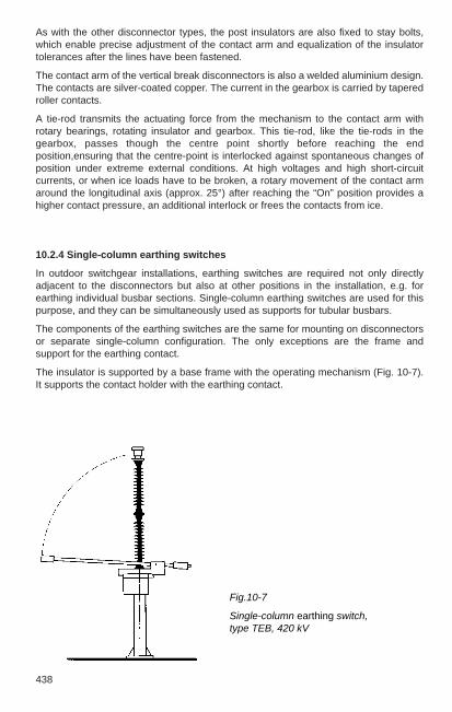
438
As with the other disconnector types, the post insulators are also fixed to stay bolts,which enable precise adjustment of the contact arm and equalization of the insulatortolerances after the lines have been fastened.
The contact arm of the vertical break disconnectors is also a welded aluminium design.The contacts are silver-coated copper. The current in the gearbox is carried by taperedroller contacts.
A tie-rod transmits the actuating force from the mechanism to the contact arm withrotary bearings, rotating insulator and gearbox. This tie-rod, like the tie-rods in thegearbox, passes though the centre point shortly before reaching the endposition,ensuring that the centre-point is interlocked against spontaneous changes ofposition under extreme external conditions. At high voltages and high short-circuitcurrents, or when ice loads have to be broken, a rotary movement of the contact armaround the longitudinal axis (approx. 25°) after reaching the “On” position provides ahigher contact pressure, an additional interlock or frees the contacts from ice.
10.2.4 Single-column earthing switches
In outdoor switchgear installations, earthing switches are required not only directlyadjacent to the disconnectors but also at other positions in the installation, e.g. forearthing individual busbar sections. Single-column earthing switches are used for thispurpose, and they can be simultaneously used as supports for tubular busbars.
The components of the earthing switches are the same for mounting on disconnectorsor separate single-column configuration. The only exceptions are the frame andsupport for the earthing contact.
The insulator is supported by a base frame with the operating mechanism (Fig. 10-7).It supports the contact holder with the earthing contact.
Fig.10-7
Single-column earthing switch, type TEB, 420 kV

10
439
Two designs are available for the different requirements: a) Vertical-reach earthingswitches for low rated voltages and rated currents, b) rotary-linear earthing switches forhigher rated voltages and currents. They differ in the design of the earthing mechanismand hence in the switching movement of the contact arm.
On the vertical-reach earthing switch, the contact arm swivels on the shaft and onlyrotates around a switching angle of about 90 degrees. In the closed position, theearthing contact is situated between the contact fingers and these are against a springstop. On the other hand, the rotary-linear earthing switch has a more complexmechanism. The contact arm first executes a rotary movement similar to that of thevertical-reach earthing switch and towards the end of the rotary movement moves on astraight line into the earthing contact. The contact blade on the contact arm is fixed inthe earthing contact so the connection can withstand even high peak currents.
10.2.5 Operating mechanisms for disconnectors and earthing switches
Disconnectors are almost entirely actuated by motor-driven operating mechanisms, butmanual mechanisms are also used for earthing switches. The operating mechanism iseither mounted directly on the base frame of the disconnector or earthing switch orplaced at operator level (1.20 m above ground level). Motor-operated mechanisms mayalso have an emergency manual actuator in case of failure of auxiliary power or foradjustments.
The operating mechanism housing has the position indicator switches for showing theswitching position and for control and interlocking, and the motor-operatedmechanisms also have contactors, etc. for controlling the actuators. The controllers aredesigned so that only one switching impulse is necessary to start the mechanism. Theyshut down automatically when the end position is reached. In the event of anemergency manual operation, the control circuit of the motor-operated mechanism isinterrupted by a safety contact, making a simultaneous actuation from the control roomimpossible. The motor-operated mechanisms can also be fitted with pushbuttons forlocal control.
The mechanisms of the disconnectors and earthing switches can be interlocked relativeto each other and to the associated circuit-breakers to prevent maloperation. Motor-operated mechanisms have an indicator switch contact for the relevant deviceincorporated into the control circuit of the mechanism. Manual and motor-operatedmechanisms can also be fitted with a locking solenoid, which prevents manualswitching when there is no power and also breaks the control circuit of the motormechanism with a separate auxiliary contact. Mechanical interlocking betweendisconnectors and earthing switches is also possible with directly mounted earthingswitches.
The mechanical actuation energy is transmitted from the motor to the actuation shaft bya spindle gear, which has an increased torque on closing and opening the main contactpoint to break ice loads.
Disconnectors and earthing switches have an operating mechanism with centre-pointinterlocking, which prevents any spontaneous changes of position under extremeexternal influences, such as short circuits, earthquakes or hurricanes.
Future generations of mechanisms will be motor-operated mechanisms withsemiconductor controls and electronic indication of switch position.

440
10.3 Switch disconnectors
High-voltage switch disconnectors are switching devices that make, carry and breakoperating currents and also carry and in part also make short-circuit currents. In theiropen position, they also form an isolating distance.
The relevant standards are the following:– DIN EN 60 265-1 (VDE 0670 Part 301) for rated voltages of 1 kV to 52 kV– DIN EN 60 265-2 (VDE 0670 Part 302) for rated voltages of 52 kV and above– Note: the standards also cover switches, i.e. devices whose open switching gap
does not meet the special requirements of an isolating distance. In practice,equipment of this type is no longer used in central Europe.
The two above standards classify the switch disconnectors into the following by theirusage:– general-purpose switch disconnectors,– switch disconnectors for limited applications and– switch disconnectors for special applications.
General-purpose switch disconnectors must be capable of making and breaking theload current for which their current path is designed (rated current) and of carrying andmaking (at the same level) short-circuit currents for a specified time (1s, 3s). Thesedevices have a very wide application. They are encountered with rated voltages of 12 kV, 24 kV and 36 kV in varying designs, primarily for operating currents to 630 A, butalso for 1250 A (Section 8.1.2). Switch disconnectors with this versatility are found inthe area of transmission voltages only as integrated devices in SF6-insulatedswitchgears.
Switch disconnectors are available for special applications in the area of air-insulatedswitchgear technology in the range up to 245 kV. They are capable of carrying highoperating currents (up to 2000 A) and short-circuit currents, but can only make andbreak much lower currents.
These devices are used as follows:– Transformer switches for smaller power supplies in the distribution network for
switching magnetizing currents and commutation currents (e.g. 100 A at up to 2.5 kVvoltage difference) when changing transformers or the power supply,
– Line switches at one end of an overhead line– Busbar section switches– Switches for short cable length (Ic < 3A).
While the switch disconnector is the most common switching device in manydistribution networks, it is much less common in transmission networks, in spite of itsmuch lower costs compared to circuit-breakers.

10
427
10 High-voltage apparatus
10.1 Definitions and electrical parameters for switchgear
Disconnectors are mechanical switching devices which provide an isolating distance inthe open position. They are capable to open or close a circuit if either a negligiblecurrent is switched or if there is no significant change in voltage between the terminalsof the poles. Currents can be carried for specified times under normal operatingconditions and under abnormal conditions (e.g. short circuit). Currents of negligiblequantity have values 0.5 A; examples are capacitive charging currents for bushings,busbars, connections, very short lengths of cable and currents of voltage transformers.
Isolating distances are gaps of specified dielectric strength in gases or liquids in theopen current paths of switching devices. They must comply with special conditions forthe protection of personnel and installations and their existence must be clearlyperceptible when the switching device is open.
Switches are mechanical switching devices, which not only make, carry and interruptcurrents under normal conditions in the network but also must carry for a specific timeand possibly make currents under specified abnormal conditions in the network (e.g.short circuit).
Switch disconnectors are switches which satisfy the requirements for an isolatingdistance specified for a disconnector in their open position.
Circuit-breakers are mechanical switching devices able to make, carry and interruptcurrents occurring in the circuit under normal conditions, and can make, carry for aspecified time and break currents occurring in the circuit (e.g. short circuit) underspecified abnormal conditions.
Earthing switches are mechanical switching devices for earthing and short-circuitingcircuits. They are capable of carrying currents for a specified time under abnormalconditions (e.g. short circuit). They are not required to carry normal operating currents.Earthing switches for transmission networks may also be required to make, carry andbreak induced currents (capacitive and inductive) under normal circuit conditions.Earthing switches with short circuit making capability shall be able to make the short-circuit current.
Fuses are switching devices that open the circuits in which they are installed by themelting of one or more parts specified and designed for the purpose of breaking thecurrent when it exceeds a given value for a sufficiently long period.
Auxiliary switches must be rated for a continuous current of at least 10 A and becapable to break the current of the control circuits. The manufacturer must providedetails. In the absence of such information, they must be capable of breaking at least 2A at 220 V d.c. at a minimum circuit time constant of 20 ms. The terminals and wiring inauxiliary circuits must be designed for at least 10 A continuous current. The auxiliaryswitches that are actuated in connection with the main contacts must be directlyactuated in both directions.

428
Electrical characteristics
(Peak) making current: peak value of the first major loop of the current in one pole of aswitching device during the transient period following the initiation of current during amaking operation.
Peak current: peak value of the first major loop of current during the transient periodfollowing initiation.
Breaking current: current in one pole of a switching device at the instant of initiation ofan arc during a breaking process.
Breaking capacity: value of the prospective breaking current that a circuit-breaker orload switch can break at a given voltage under prescribed conditions for application andperformance; e.g. overhead line (charging current) breaking capacity.
Short-line fault: short circuit on an overhead line at a short but not negligible distancefrom the terminals of the circuit-breaker.
Out of phase (making or breaking) capacity: making or breaking capacity for which thespecified conditions for use and behaviour include the loss or the lack of synchronismbetween the parts of an electrical system on either side of the circuit-breaker.
Applied voltage: voltage between the terminals of a circuit-breaker pole immediatelybefore making the current.
Recovery voltage: voltage occurring between the terminals of a circuit-breaker poleafter interruption of the current.
Opening time: interval of time between application of the auxiliary power to the openingrelease of a switching device and the separation of the contacts in all three poles.
Closing time: interval of time between application of the auxiliary power to the closingcircuit of a switching device and the contact touch in all poles.
Break time: interval of time between the beginning of the opening time of a switchingdevice and the end of the arcing time.
Make time: interval of time between application of the auxiliary power to the closingcuircuit of a switching device and the instant in which the current begins to flow in themain circuit.
Rated value: value of a characteristic quantity used to define the operating conditionsfor which a switching device is designed and built and which must be verified by themanufacturer.
Rated normal current: the current that the main circuit of a switching device cancontinuously carry under specified conditions for use and behaviour. See below forstandardized values.
Rated short-time withstand current: current that a switching device in closed positioncan carry during a specified short time under prescribed conditions for use andbehaviour. See below for standardized values.
Rated voltage: upper limit of the highest voltage of the network for which a switchingdevice is rated. See below for standardized values.
10
429
Additional rated values:rated withstand current, rated making current, rated short-circuit breaking capacity etc.
Standard value: rated value based on official specifications to be used for designing adevice.
Standardized rated voltages: 3.6; 7.2; 12; 17.5; 24; 36; 52; 72.5; 100; 123; 145; 170;245; 300; 362; 420; 550; 800 kV.
Standardized rated normal currents: 200; 250; 400; 500; 630; 800; 1000; 1250; 1600;2000; 2500; 3150; 4000; 5000; 6300 A.
Standardized rated short-time currents: 6.3; 8; 10; 12,5; 16; 20; 25; 31,5; 40; 50; 63;80; 100 kA.
Rated insulation level: standardized combination of the rated values for the lightningimpulse withstand voltage, the switching impulse withstand voltage (if applicable) andthe short-time power frequency withstand voltage assigned to a rated voltage. Asstandardized insulation level, only combinations of values from one and the same lineof Table 10-1 are valid.
Rated short-duration power frequency withstand voltage: rms value of the sinusoidala.c. voltage at operating frequency that the insulation of a device must withstand underthe specified test conditions for 1 minute.
Rated lightning impulse withstand voltage: peak value of the standard voltage surge1.2/50 µs that the insulation of a device must withstand.
Rated switching impulse withstand voltage: peak value of the unipolar standard voltagesurge 250/2500 µs which the insulation of a device with a rated voltage of 300 kV andabove must withstand.
Note:
For disconnectors and specific (asynchronous) circuit-breakers for rated voltages of300 kV and above, the isolating distances or breaker gaps are tested with combinedvoltage so that the power frequency test voltage (Table 10-1, peak values inparentheses) is applied at one terminal and the counterpolar test surge voltage(lightning or switching) occurs in the time range of the maximum voltage at the otherterminal. The test with combined voltage was originally known as the bias test.

430
Table 10-1
Standardized rated insulation level for disconnectors, switches, circuit-breakers andearthing switches according to DIN EN 60 694 (VDE 0670 Part 1000)
Rated short-duration power Rated frequency withstand voltage lightning impulse withstand voltage
kV (rms value) kV (peak value)
Phase to earth, Phase to earth,between the phases between the phases
and across Across the and across Across thethe open isolating distance of the open isolating distance
breaker gap breaker gap
1 2 3 4 5
3.6 10 12 20 2340 46
7.2 20 23 40 4660 70
12 28 32 60 7075 85
17.5 38 45 75 8595 110
24 50 60 95 110125 145
36 70 80 145 165170 195
52 95 110 250 290
72.5 140 160 325 375
100 150 175 380 440185 210 450 520
123 185 210 450 520
230 265 550 630
145 230 265 550 630
275 315 650 750
170 275 315 650 750
325 375 750 860
245 360 415 850 950395 460 950 1 050460 530 1 050 1 200
(continued)
Rated voltagekV (rms value)

10
431
Table 10-1 (continued)
Rated short-duration Rated Rated switching impulse withstand voltage power frequency withstand voltage lightning impulse withstand voltage kV (peak value)
kV (rms value) kV (peak value)
Phase to earth Across the open Phase to earth Across the open Phase to earth Between Across theand between breaker gap and between breaker gap and across the phases isolating distancethe phases and/or the phases and/or the open
isolating distance isolating distance breaker gap
1 2 3 4 5 6 7 8
300 380 435 950 950 (+ 170) 750 1 125 700 (+ 245)
1 050 1 050 (+ 170) 850 1 275
362 450 520 1 050 1 050 (+ 205) 850 1 275 800 (+ 295)
1 175 1 175 (+ 205) 950 1 425
420 520 610 1 300 1 300 (+ 240) 950 1 425 900 (+ 345)
1 425 1 425 (+ 240) 1 050 1 575
550 620 800 1 425 1 425 (+ 315) 1 050 1 680 900 (+ 450)
1 550 1 550 (+ 315) 1 175 1 760
800 830 1 150 1 800 1 800 (+ 455) 1 300 2 210 1 100 (+ 650)
2 100 2 100 (+ 455) 1 425 2 420
The values in parentheses are the peak values of the a.c. voltage applied to the opposite terminal.
Rated voltagekV (rms value)

432
10.2 Disconnectors and earthing switches
Disconnectors are used for galvanic isolation of networks or sections of switchgearinstallations. As an independent air-insulated device, they form a visible isolatingdistance in their open position. They are suitable for switching small currents (< 0.5 A)or also larger currents if the voltage does not change significantly between the contactsof a disconnector pole during switching (commutation currents).
Disconnectors can carry currents under operating conditions continuously and underabnormal conditions, such as short circuit, for a specified time (1s, 3s).
More than 10 different designs are in use around the world. The most important arerotary disconnectors, two-column vertical break disconnectors and single-columndisconnectors.
Earthing switches are used for earthing and short-circuiting deenergized stationcomponents. Earthing switches can withstand currents during a specified time (1s, 3s)under abnormal conditions, such as a short circuit, but they are not required to carrycontinuous operating currents.
In general, earthing switches are combined with the adjacent disconnectors to form oneunit. However, earthing switches can also be installed separately.
The applicable standard for disconnectors is DIN EN 60 129 (VDE 0670 Part 2). IEC 61128 is specifically applicable for switching commutation currents withdisconnectors.
DIN EN 60 129 (VDE 0670 Part 2) is also applicable for earthing switches. In addition,DIN EN 61 129 (VDE 0670 Part 212) shall be considered with reference to switchinginduced currents.
Selection of the disconnector design is primarily guided by the layout of the installation(structural design), see Section 11.3.3. The ABB disconnector range can cover virtuallyall important layout variations in the ranges 72.5 to 800 kV, (rated voltage), 1250 to4000 A (rated current) and 63 to 160 kA (rated peak withstand current).
10.2.1 Rotary disconnectors
Two-column rotary disconnectors SGF
This disconnector type is used by ABB for rated voltages of 72.5 to 420 kV (in individualcases also for 525 kV), preferably in smaller installations and also in larger switchgearinstallations as incoming feeder or sectionalizing disconnector. An earthing switch canbe installed on both sides.
As shown in Fig. 10-1, the two rotating bases are mounted on a sectional steel frameand connected by a braced tie-rod. The insulators (post insulators) are fixed to therotating bases and carry the swivel heads with the arms and the high-voltage contacts.Both arms swivel 90 degrees with their insulators during the switching movement.Two-column rotary disconnectors in their open position form a horizontal isolating distance.The rotary bases are weather protected and have maintenance-free ball bearings. Therotary bases are fastened on stay bolts, which allow precise adjustment of the contactsystem after the lines have been rigged and also compensate the insulator tolerances.
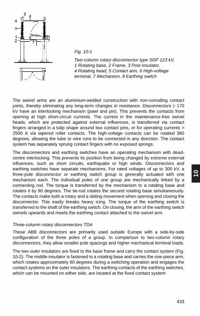
10
433
The swivel arms are an aluminium-welded construction with non-corroding contactjoints, thereby eliminating any long-term changes in resistance. Disconnectors ≥ 170kV have an interlocking mechanism (pawl and pin). This prevents the contacts fromopening at high short-circuit currents. The current in the maintenance-free swivelheads, which are protected against external influences, is transferred via contactfingers arranged in a tulip shape around two contact pins, or for operating currents >2500 A via tapered roller contacts. The high-voltage contacts can be rotated 360degrees, allowing the tube or wire runs to be connected in any direction. The contactsystem has separately sprung contact fingers with no exposed springs.
The disconnectors and earthing switches have an operating mechanism with dead-centre interlocking. This prevents its position from being changed by extreme externalinfluences, such as short circuits, earthquake or high winds. Disconnectors andearthing switches have separate mechanisms. For rated voltages of up to 300 kV, athree-pole disconnector or earthing switch group is generally actuated with onemechanism each. The individual poles of one group are mechanically linked by aconnecting rod. The torque is transferred by the mechanism to a rotating base androtates it by 90 degrees. The tie-rod rotates the second rotating base simultaneously.The contacts make both a rotary and a sliding movement when opening and closing thedisconnector. This easily breaks heavy icing. The torque of the earthing switch istransferred to the shaft of the earthing switch. On closing, the arm of the earthing switchswivels upwards and meets the earthing contact attached to the swivel arm.
Three-column rotary disconnectors TDA
These ABB disconnectors are primarily used outside Europe with a side-by-sideconfiguration of the three poles of a group. In comparison to two-column rotarydisconnectors, they allow smaller pole spacings and higher mechanical terminal loads.
The two outer insulators are fixed to the base frame and carry the contact system (Fig.10-2). The middle insulator is fastened to a rotating base and carries the one-piece arm,which rotates approximately 60 degrees during a switching operation and engages thecontact systems on the outer insulators. The earthing contacts of the earthing switches,which can be mounted on either side, are located at the fixed contact system.
Fig. 10-1
Two-column rotary disconnector type SGF 123 kV, 1 Rotating base, 2 Frame, 3 Post insulator, 4 Rotating head, 5 Contact arm, 6 High-voltageterminal, 7 Mechanism, 8 Earthing switch

434
10.2.2 Single-column (pantograph) disconnector TFB
In installations for higher voltages (≥ 170 kV) and multiple busbars, the single-columndisconnector (also referred to as pantograph or vertical-reach disconnector) shown inFig. 10-3 requires less space than other disconnector designs. For this reason andbecause of the clear station layout, it is used in many switchgear installations. Theswitch status is clearly visible with the vertical isolating distance.
Fig.10-3
Single-column disconnector type TFB245 kV, 1 Rotating bearing, 2 Frame, 3 Post insulator, 4 Rotating insulator, 5 Pantograph, 6 Gearbox, 7 Mechanism,8 Earthing switch, 9 Fixed contact
The three-column rotary disconnectors have the same components as the two-columnrotary disconnectors described above. The same information applies for contact arm,swivel bases, contact system and interlocking mechanism, centre-point interlock,earthing switch and mechanical connection of the poles.
Fig.10-2
Three-column rotary disconnector type TDA, 145 kV, 1 Swivel base, 2 Frame, 3 Post insulator, 4 Rotating insulator, 5 Contact arm, 6 High-voltageterminal, 7 Mechanisms, 8 Earthing switch

10
435
The base of the disconnector is the frame, which holds the post insulator carrying thehead piece with the pantograph and the gearbox. The actuating force is transferredthrough the rotating insulator to the gearbox. The suspended contact is mounted on thebusbar situated above the disconnector. On closing, it is gripped between thepantograph arms. During the closing movement, the pantograph arms swivel through awide range and are therefore capable of carrying the fixed contact even under extremeposition changes caused by weather conditions. The feeder line is connected to thehigh-voltage terminal of the gearbox. In general, the single-column disconnector allowshigher mechanical terminal loads than the two-column rotary disconnector.
The frame with the rotary bearing for the rotating insulator is fastened to the supportwith four stay bolts. They allow the disconnector to be accurately adjusted relative tothe suspended contact.
The pantograph is a welded aluminium construction. It is fixed to the gearbox with thepantograph shaft by pins, preventing the pantograph unit from moving during the entirelifetime. This also ensures long-term high contact pressure between the contacts of thepantograph and the fixed contact. A contact force of 700 to 1500 N (depending on thepantograph design) not only ensures secure current transfer but also breaks heavyicing. Tapered roller contacts transfer current from the gearbox to the lower pantographarms and make the connection from the lower to the upper pantograph arm.
The contact bars on the top of the pantographs and the fixed contact are silver-coatedcopper, for heavy duty or special cases they have a fine silver inlay. This results in lowcontact erosion, good current transfer and long service intervals.
Disconnectors for high short-circuit currents have a damping device between the armjoints. In the event of a short circuit, it prevents any reduction in the contact pressureand damps the oscillations of the pantograph caused by the short-circuit current.
The single-column disconnectors have a centre-point interlock in the gearbox andtherefore cannot change their position spontaneously. It retains the switch position inany case, even if the rotating insulator breaks or if the disconnector is subjected toextreme vibrations caused by earthquakes or short-circuit forces. Anti-corona fittings onthe ends of the arms act as a stop for the suspended contact if it moves in a verticaldirection. Even under high tensile forces, it is securely held in the contact zone in theevent of a short circuit.
Special designs of single-support disconnectors have been used in installations forhigh-voltage direct current transmission (HDVC) for many years.
A rotary-linear earthing switch (Section 10.2.4) can be installed on every disconnectorpole.
In general, single-column disconnectors and the associated earthing switches areactuated by one mechanism each per pole.
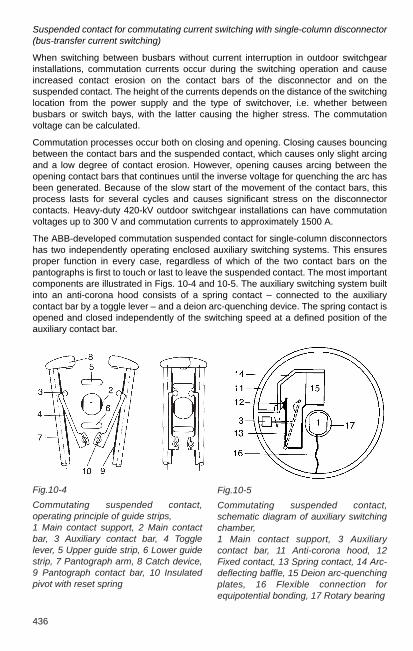
436
Fig.10-4
Commutating suspended contact,operating principle of guide strips,1 Main contact support, 2 Main contactbar, 3 Auxiliary contact bar, 4 Togglelever, 5 Upper guide strip, 6 Lower guidestrip, 7 Pantograph arm, 8 Catch device,9 Pantograph contact bar, 10 Insulatedpivot with reset spring
Fig.10-5
Commutating suspended contact,schematic diagram of auxiliary switchingchamber,1 Main contact support, 3 Auxiliarycontact bar, 11 Anti-corona hood, 12Fixed contact, 13 Spring contact, 14 Arc-deflecting baffle, 15 Deion arc-quenchingplates, 16 Flexible connection forequipotential bonding, 17 Rotary bearing
Suspended contact for commutating current switching with single-column disconnector(bus-transfer current switching)
When switching between busbars without current interruption in outdoor switchgearinstallations, commutation currents occur during the switching operation and causeincreased contact erosion on the contact bars of the disconnector and on thesuspended contact. The height of the currents depends on the distance of the switchinglocation from the power supply and the type of switchover, i.e. whether betweenbusbars or switch bays, with the latter causing the higher stress. The commutationvoltage can be calculated.
Commutation processes occur both on closing and opening. Closing causes bouncingbetween the contact bars and the suspended contact, which causes only slight arcingand a low degree of contact erosion. However, opening causes arcing between theopening contact bars that continues until the inverse voltage for quenching the arc hasbeen generated. Because of the slow start of the movement of the contact bars, thisprocess lasts for several cycles and causes significant stress on the disconnectorcontacts. Heavy-duty 420-kV outdoor switchgear installations can have commutationvoltages up to 300 V and commutation currents to approximately 1500 A.
The ABB-developed commutation suspended contact for single-column disconnectorshas two independently operating enclosed auxiliary switching systems. This ensuresproper function in every case, regardless of which of the two contact bars on thepantographs is first to touch or last to leave the suspended contact. The most importantcomponents are illustrated in Figs. 10-4 and 10-5. The auxiliary switching system builtinto an anti-corona hood consists of a spring contact – connected to the auxiliarycontact bar by a toggle lever – and a deion arc-quenching device. The spring contact isopened and closed independently of the switching speed at a defined position of theauxiliary contact bar.

10
437
Because the arc only lasts for about 25 ms on average during opening, the contacterosion on the spring contact system remains slight and the current is safely interruptedbefore the pantograph contact bar separates. Separating the main and auxiliary contactsystems keeps the latter completely free from the effects of forces resulting from a shortcircuit. Short-circuit testing has confirmed a peak withstand current strength of 200 kA.Each switching system can take at least 350 switching cycles at commutation currentsup to 1600 A and commutation voltages up to 330 V.
Installing commutation suspended contacts provides the system operator with flexibilityand reliability of operation. Older installations can be upgraded by replacing thesuspended contacts. Installations with switchgear from other manufacturers can alsobe retrofitted with ABB commuting suspended contacts.
10.2.3 Two-column vertical break disconnectors
This type of disconnector is preferred for higher voltages (≥ 170 kV) as a feeder orbranch disconnector (at 1 1/2 circuit-breaker structure, Section 11.3.3). It differs fromtwo-column rotary disconnectors by smaller phase spacings (with side-by-sideconfiguration) and higher mechanical terminal loads. In its open state, there is ahorizontal isolating distance with the contact arm open upwards.
As shown in Fig. 10-6, the two post insulators are mounted on a frame. The gearboxwith contact arm and high-voltage terminal and the fixed contact with high-voltageterminal are mounted on them. The rotating insulator fastened to the rotary bearingtransfers the actuating force to the gearbox, which transmits the force into a torque foropening the contact arm.
Each side of the disconnector can be fitted with an earthing switch (Section 10.2.4)depending on the requirements. The associated earthing contacts are installed on thegearbox or on the fixed contact.
For rated voltages of up to 245 kV one mechanism per three-phase disconnector orearthing switch group is sufficient, at higher nominal voltages one mechanism per poleis generally used.
Fig.10-6
Vertical break 525 kV, 1 Rotary bearing, 2 Frame, 3 Postinsulator, 4 Rotating insulator, 5 Contact arm, 6 High-voltageterminal, 7 Mechanism, 8 Gearbox, 9 Fixed contact

438
As with the other disconnector types, the post insulators are also fixed to stay bolts,which enable precise adjustment of the contact arm and equalization of the insulatortolerances after the lines have been fastened.
The contact arm of the vertical break disconnectors is also a welded aluminium design.The contacts are silver-coated copper. The current in the gearbox is carried by taperedroller contacts.
A tie-rod transmits the actuating force from the mechanism to the contact arm withrotary bearings, rotating insulator and gearbox. This tie-rod, like the tie-rods in thegearbox, passes though the centre point shortly before reaching the endposition,ensuring that the centre-point is interlocked against spontaneous changes ofposition under extreme external conditions. At high voltages and high short-circuitcurrents, or when ice loads have to be broken, a rotary movement of the contact armaround the longitudinal axis (approx. 25°) after reaching the “On” position provides ahigher contact pressure, an additional interlock or frees the contacts from ice.
10.2.4 Single-column earthing switches
In outdoor switchgear installations, earthing switches are required not only directlyadjacent to the disconnectors but also at other positions in the installation, e.g. forearthing individual busbar sections. Single-column earthing switches are used for thispurpose, and they can be simultaneously used as supports for tubular busbars.
The components of the earthing switches are the same for mounting on disconnectorsor separate single-column configuration. The only exceptions are the frame andsupport for the earthing contact.
The insulator is supported by a base frame with the operating mechanism (Fig. 10-7).It supports the contact holder with the earthing contact.
Fig.10-7
Single-column earthing switch, type TEB, 420 kV

10
439
Two designs are available for the different requirements: a) Vertical-reach earthingswitches for low rated voltages and rated currents, b) rotary-linear earthing switches forhigher rated voltages and currents. They differ in the design of the earthing mechanismand hence in the switching movement of the contact arm.
On the vertical-reach earthing switch, the contact arm swivels on the shaft and onlyrotates around a switching angle of about 90 degrees. In the closed position, theearthing contact is situated between the contact fingers and these are against a springstop. On the other hand, the rotary-linear earthing switch has a more complexmechanism. The contact arm first executes a rotary movement similar to that of thevertical-reach earthing switch and towards the end of the rotary movement moves on astraight line into the earthing contact. The contact blade on the contact arm is fixed inthe earthing contact so the connection can withstand even high peak currents.
10.2.5 Operating mechanisms for disconnectors and earthing switches
Disconnectors are almost entirely actuated by motor-driven operating mechanisms, butmanual mechanisms are also used for earthing switches. The operating mechanism iseither mounted directly on the base frame of the disconnector or earthing switch orplaced at operator level (1.20 m above ground level). Motor-operated mechanisms mayalso have an emergency manual actuator in case of failure of auxiliary power or foradjustments.
The operating mechanism housing has the position indicator switches for showing theswitching position and for control and interlocking, and the motor-operatedmechanisms also have contactors, etc. for controlling the actuators. The controllers aredesigned so that only one switching impulse is necessary to start the mechanism. Theyshut down automatically when the end position is reached. In the event of anemergency manual operation, the control circuit of the motor-operated mechanism isinterrupted by a safety contact, making a simultaneous actuation from the control roomimpossible. The motor-operated mechanisms can also be fitted with pushbuttons forlocal control.
The mechanisms of the disconnectors and earthing switches can be interlocked relativeto each other and to the associated circuit-breakers to prevent maloperation. Motor-operated mechanisms have an indicator switch contact for the relevant deviceincorporated into the control circuit of the mechanism. Manual and motor-operatedmechanisms can also be fitted with a locking solenoid, which prevents manualswitching when there is no power and also breaks the control circuit of the motormechanism with a separate auxiliary contact. Mechanical interlocking betweendisconnectors and earthing switches is also possible with directly mounted earthingswitches.
The mechanical actuation energy is transmitted from the motor to the actuation shaft bya spindle gear, which has an increased torque on closing and opening the main contactpoint to break ice loads.
Disconnectors and earthing switches have an operating mechanism with centre-pointinterlocking, which prevents any spontaneous changes of position under extremeexternal influences, such as short circuits, earthquakes or hurricanes.
Future generations of mechanisms will be motor-operated mechanisms withsemiconductor controls and electronic indication of switch position.

440
10.3 Switch disconnectors
High-voltage switch disconnectors are switching devices that make, carry and breakoperating currents and also carry and in part also make short-circuit currents. In theiropen position, they also form an isolating distance.
The relevant standards are the following:– DIN EN 60 265-1 (VDE 0670 Part 301) for rated voltages of 1 kV to 52 kV– DIN EN 60 265-2 (VDE 0670 Part 302) for rated voltages of 52 kV and above– Note: the standards also cover switches, i.e. devices whose open switching gap
does not meet the special requirements of an isolating distance. In practice,equipment of this type is no longer used in central Europe.
The two above standards classify the switch disconnectors into the following by theirusage:– general-purpose switch disconnectors,– switch disconnectors for limited applications and– switch disconnectors for special applications.
General-purpose switch disconnectors must be capable of making and breaking theload current for which their current path is designed (rated current) and of carrying andmaking (at the same level) short-circuit currents for a specified time (1s, 3s). Thesedevices have a very wide application. They are encountered with rated voltages of 12 kV, 24 kV and 36 kV in varying designs, primarily for operating currents to 630 A, butalso for 1250 A (Section 8.1.2). Switch disconnectors with this versatility are found inthe area of transmission voltages only as integrated devices in SF6-insulatedswitchgears.
Switch disconnectors are available for special applications in the area of air-insulatedswitchgear technology in the range up to 245 kV. They are capable of carrying highoperating currents (up to 2000 A) and short-circuit currents, but can only make andbreak much lower currents.
These devices are used as follows:– Transformer switches for smaller power supplies in the distribution network for
switching magnetizing currents and commutation currents (e.g. 100 A at up to 2.5 kVvoltage difference) when changing transformers or the power supply,
– Line switches at one end of an overhead line– Busbar section switches– Switches for short cable length (Ic < 3A).
While the switch disconnector is the most common switching device in manydistribution networks, it is much less common in transmission networks, in spite of itsmuch lower costs compared to circuit-breakers.
10
441
10.4 Circuit-breakers
10.4.1 Function, selection
High-voltage circuit-breakers are mechanical switching devices capable of making,carrying continuously and breaking electrical currents, both under normal circuitconditions and, for a limited period, abnormal circuit conditions, such as in the event ofa short circuit. Circuit-breakers are used for switching overhead lines, cable feeders,transformers, reactor coils and capacitors. They are also used in bus ties in installationswith multiple busbars to allow power to be transmitted from one busbar to another.
Specially designed breakers are used for specific duties such as railways, where theyhave to extinguish longer-burning arcs (longer half-wave) in 16 2/3-Hz networks.Breakers used with smelting furnaces frequently operate with reduced actuating forceand lower breaking capacity. This leads to less wear in spite of the high switchingfrequency and to long service intervals.
The following points are important when selecting circuit-breakers:
– maximum operating voltage on location– installation height above sea-level – maximum load current occurring on location– maximum short-circuit current occurring on location– network frequency – duration of short-circuit current – switching cycle – special operational and climatic conditions
Important national and international standards:
IEC DIN VDE
DIN VDE 0670 – 101 (0670 Part 101) General and definitionsDIN VDE 0670 – 102 (0670 Part 102) ClassificationDIN VDE 0670 – 103 (0670 Part 103) Design and construction60056DIN VDE 0670 – 104 (0670 Part 104) Type and routine testingDIN VDE 0670 – 105 (0670 Part 105) Selection of circuit-breakers
for serviceDIN VDE 0670 – 106 (0670 Part 106) Information in enquiries, tenders
and orders60427 DIN EN 60 427 (0670 Part 108) Synthetic testing60694 DIN EN 60 694 (0670 Part 1000) Common specifications for
high voltage switchgear andcontrolgear standards
ANSI (American National Standards Institution) C 37 04 –1979 Rating structureC 37 06 –1979 Preferred ratingsC 37 09 –1979 Test procedureC 37 010 –1979 Application guideC 37 011 –1979 Application guide for transient recovery voltageC 37 012 –1979 Capacitance current switching
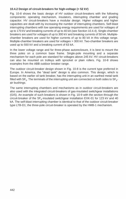
442
10.4.2 Design of circuit-breakers for high-voltage (> 52 kV)
Fig. 10-8 shows the basic design of HV outdoor circuit-breakers with the followingcomponents: operating mechanism, insulators, interrupting chamber and gradingcapacitor. HV circuit-breakers have a modular design. Higher voltages and highercapacities are dealt with by increasing the number of interrupting chambers. Self-blastinterrupting chambers with low operating energy requirements are used for voltages ofup to 170 kV and breaking currents of up to 40 kA (see Section 10.4.4). Single-chamberbreakers are used for voltages of up to 300 kV and breaking currents of 50 kA. Multiple-chamber breakers are used for higher currents of up to 80 kA in this voltage range.Multiple-chamber breakers are used for voltages > 300 kV. Two-chamber breakers areused up to 550 kV and a breaking current of 63 kA.
In the lower voltage range and for three-phase autoreclosure, it is best to mount thethree poles on a common base frame. Single-pole mounting and a separatemechanism for each pole are standard for voltages above 245 kV. HV circuit-breakerscan also be mounted on trolleys with sprocket or plain rollers. Fig. 10-8 showsexamples from the ABB outdoor breaker range.
The outdoor circuit-breaker design shown in Fig. 10-8 is the current type preferred inEurope. In America, the “dead tank” design is also common. This design, which isbased on the earlier oil tank breaker, has the interrupting unit in an earthed metal tankfilled with SF6. The terminals of the interrupting unit are connected on both sides to SF6-air bushings.
The same interrupting chambers and mechanisms as in outdoor circuit-breakers arealso used with the integrated circuit-breakers of gas-insulated switchgear installations(GIS). An example of such breakers is shown in Fig. 10-9 with the section through thecircuit-breaker of the SF6-insulated switchgear installation EXK-01 for 123 kV and 40kA. The self-blast interrupting chamber is identical to that of the outdoor circuit-breakertype LTB-D1; the three-pole circuit-breaker is operated by the HMB-1 mechanism.

10
443
Rated voltage kV 123 123-170 245-300 420-(550)
Rated short-circuit 40 40 50 63breaking current kA
Breaker arrangement
Breaker type ELF-SD3-1 LTB-D1 HPL-B1 HPL-B216 2⁄₃ Hz
Mechanism type HMB-1 HMB-1/HMB-1S HMB-4 HMB-8
Fig.10-8
ABB SF6 outdoor circuit-breaker, standard types for the central European region

444
Fig.10-9
GIS circuit-breaker EXK-01 with SF6 self-blast interrupting chamber and hydraulicspring mechanism HMB-1
12
8
3
6
5
4
7
1
1
2
2
1 Barrier insulator2 Feed conductor3 Current transformer
4 Interrupting chamber5 Chamber insulator6 Cover
7 Rotary feed8 Mechanism

10
445
10.4.3 Interrupting principle and important switching cases
There are two basic arc-extinction processes.
Direct current extinction, Fig. 10-10
A d.c. arc can only be extinguished byforcing a current zero. This means thatthe arc voltage Us must be higher thanthe voltage at the breaker LS. Asufficiently high arc voltage can be builtup – by reasonable means – only in lowand medium voltage d.c. circuits(magnetic blow-out breakers). In high-voltage d.c. circuits, the voltage must belowered appropriately to extinguish thed.c. arc and/or artificial current zerosmust be created by inserting a resonantcircuit (see Fig. 11-39).
Fig.10-10
Direct current extinction a) simplifiedequivalent circuit, b) curves of current isand arc voltage us, t1 initiation of shortcircuit, t2 contact separation
Fig.10-11
Alternating current extinction, a) simplified equivalent circuit, b) curvesof short-circuit current is and recoveryvoltage us, t1 contact separation, t2 arcextinction, S rate of rise of recoveryvoltage
Alternating current extinction, Fig. 10-11
A.C. arcs may extinguish at every currentzero. In high-voltage circuits and withoutspecial measures, the arc re-ignitesimmediately after passing zero crossing,so that the arc continues to burn. The arcplasma is intensively cooled in theinterrupting chambers of HV circuit-breakers with the result that it loses itselectrical conductivity at current zero andthe recovery voltage is not sufficient forre-ignition.
is
i

446
Various switching cases
Circuit-breakers must handle various switching cases that place different requirementson the breaker depending on their location.
Terminal fault (symmetrical short-circuit current), Fig. 10-13The terminal fault is a short circuit on the load side of a breaker in the immediate vicinityof the breaker terminals. The short-circuit current is symmetrical if the fault begins at thevoltage maximum. The recovery voltage oscillates to the value of the driving voltage.Rate of rise and amplitude of the transient voltage are determined by the networkparameters. The values to be used in testing are defined in the relevant standards(Section 10.4.1).
Voltage stress of the breaker, Fig. 10-12
When interrupting an inductive load (Fig. 10-12a), the breaker voltage oscillates to thepeak value of the recovery voltage. The breaker must be able to withstand the rate ofrise of the recovery voltage and its peak value. Once the arc is quenched, the dielectricstrength between the contacts must build up more quickly than the recovery voltage toprevent re-ignition.
When interrupting a purely resistive load (Fig. 10-12b), current zero and voltage zerocoincide. The recovery voltage at the breaker rises sinusoidally with the operatingfrequency. The breaker gap has sufficient time to recover dielectric strength.
When switching a capacitive load (Fig. 10-12c), the supply-side voltage (infeed breakerterminal) oscillates at system frequency after current interruption between ± û, while thecapacitor-side terminal remains charged at + û.
Fig.10-12
Recovery voltage uS when breaking a) inductive load, b) resistive load, c) capacitiveload

10
447
Fig.10-13
Terminal fault, a) simplified equivalentcircuit, b) curves of recovery voltage us
and short-circuit current is, 1 decaying d.c.current component
Fig.10-14
Short-line fault, a) simplified equivalent circuit, b) recovery voltage us across thebreaker, 1 Line, 2 Sawtooth shape of us
Terminal fault (asymmetrical short-circuit current), Fig. 10-13
A more or less high d.c. current component must be switched in addition to thesymmetrical short-circuit current depending on the opening time of the breaker. The d.c.current component of the short-circuit current depends on the moment of short-circuitinitiation (max. at voltage zero) and on the time constants of the network supply-sidecomponents, such as generators, transformers, cables and HV lines. In accordancewith IEC and DIN VDE, a time constant of 45 ms is set as standard. This means a d.c.current component of about 40% to 50% with the usual opening times of modern SF6
outdoor breakers.
Short-line fault, Fig. 10-14
Short line faults are short circuits on overhead lines at a short distance (up to a fewkilometres) from the breaker. They impose a particularly severe stress on the breakerbecause two transient voltages are superimposed: the transient voltage of the supplynetwork and the transient voltage on the line side. The superimposition results in aparticularly high rate of rise of the voltage with only a minor reduction of the short-circuitcurrent. The critical distance of the short circuit depends on the current, voltage andarc-quenching medium.

448
Interruption of small inductive currents, Fig. 10-16
Depending on the network configuration, interruption of small inductive currents, suchas reactor coils or magnetizing currents from transformers, causes a rapid rise of therecovery voltage and under some circumstances high overvoltage resulting fromcurrent chopping before the natural zero crossing.
The overvoltages are also heavily dependent on the individual properties of the loadcircuit (inductance L2 and capacitance C2). There is no generally applicable test circuitthat covers all load cases occurring in the network. However, in transmission networksan overvoltage of 2.5 pu is normally not exceeded.
Switching under out-of-phase conditions (phase opposition), Fig. 10-15
The (power-frequency) voltage stress is severe if the phase angle of the systems oneither side of the breaker are different (system components fall out of step because ofoverload or incorrect synchronization of generator circuit-breakers).
Fig.10-15
Switching under out-of-phase conditions,a) simplified equivalent circuit,b) voltage stress on circuit-breaker
Fig.10-16
Interruption of smallinductive currents, a) simplified equivalentcircuit, b) curve ofcurrent and voltageswith current choppingwithout restriking, c) voltage curve whenrestriking occurs
Switching of capacitive currents, Fig. 10-17
Since breakers that prevent restriking are generally available, this switching case doesnot cause extreme stress (see Fig. 10-12c). However, theoretically, repeated restrikingcan increase the voltage load to several times the peak value of the driving voltage.

10
Switching of unloaded lines and cables:
The capacitance per unit length of line or cable imposes a similar situation as with theswitching of capacitors
Closing of inductive currents, Fig. 10-18
The most important switching case of this type for switchgear technology is the closingon short circuit. The timing of the contact making with reference to the driving voltagedetermines the effects on the contact system. Fig. 10-18a shows the closing operationwith pre-arcing on contact proximity in the area of the peak value of the persistentvoltage and the associated symmetrical fault current curve. Fig. 10-18b shows thecurve on contact making in the area of the zero crossing of the persistent voltage withthe peak value increased to almost double the value (1.8 times) by a transient directcurrent component in the current path.
One breaker pole nearly always reaches this curve during three-pole switching withsimultaneous closing time of the three breaker poles.
Fig.10-17
Breaking capacitive currents, a) Simplified equivalentcircuit, b) Curves of current and voltage, c) Currentand voltage characteristics when restriking occurs
cL
449
Fig.10-18Making inductive currents: t1 = instant of pre-arcingt2 = instant of contact touchS = contact patha) symmetrical current with pre-arcingta = pre-arcing durationb) asymmetrical current withmaximum peak current
ta
ss
Closing of unloaded overhead lines
Overhead lines can be shown in the electrical equivalent circuit diagram ascombinations of series-connected inductances and capacitances to earth. Duringclosing of long overhead lines, due to reflections of the voltage at the open end of theline, voltage increase of about 100% can occur. For this reason, at high transmissionvoltages and very long lines (> 300 km) circuit-breakers are fitted with closing resistorsor closing is single-phase synchronized at the instant of zero crossing of the persistentvoltage.

450
Fig.10-19a:
Synthetic test circuit with current injectionG: short-circuit generator, DS: making switch, HS: auxiliary breaker, PS: test breaker, ik: short-circuit current, is: injection current, ips =(ik + is): test current through the testbreaker, C, C1, C2, R1, L2: element of the synthetic circuit
is
ip
DS HS
VSR1
C1
L2C2
C
iK
An oscillogram of a make (c)/break (o) operation in a synthetic test circuit is shown inFig. 10-19c.
Short-circuit making and breaking tests
Making and breaking tests of circuit-breakers are performed in high-power testlaboratories. The short-circuit current for the test is supplied by specially designedgenerators. The single-phase breaking power of a 420 kV circuit-breaker with a ratedshort-circuit current of 63 kA is approximately 15 000 MVA, which cannot be performedin a direct test circuit even by the most powerful test laboratory. Therefore, as early asthe 1940s synthetic test circuits were developed for testing breakers with high short-circuit switching capability.
The basic reasoning behind a synthetic breaking test is that in the event of a shortcircuit, the short-circuit current and the recovery voltage do not occur simultaneously.This allows current and voltage to be supplied from two different sources. Fig. 10-19ashows the simplified test circuit for a synthetic test with current injection.
When test- and auxiliary-breakers are closed, the short circuit is initiated by closing themaking switch. Auxiliary-breaker and test-breaker open at approximately the sametime. Shortly before current zero of the current that is to be interrupted, the spark gap isignited and an oscillating current of high frequency with an amplitude of some kA issuperimposed on the short-circuit current in the test-breaker (Fig. 10-19b). The test-circuit elements must be selected so that the rate of current rise of the oscillatingcurrent at zero crossing coincides with the rate of rise of the high current.
PS
ik
is
ips
Fig.10-19b:
Current versus time in the synthetictest circuit
The auxiliary breaker interrupts theshort-circuit current ik at zerocrossing 1, the test breaker interruptsthe test current ips at zero crossing 2,is is the injection current.
iK
is
ip
i
t1 2
ips
ik
is
i
t
G

10
451
Fig.10-19c:
Oscillogram of a CO operation in the synthetic test circuit (half-pole test)
UCC Generator voltageUTB recovery voltage across
the breaker gap ITB (= ips) current through the test object
0 50050 100 150 200 250 300 350 400 450ms50 ms/div
40
-40
kVolt
U_CC40 k/div
400
-400
kVolt
U_TB400 k/div
180
-180
kA
I_TB180 k/div
12
-12
kA
I_INJ12 k/div
20
-220
mm
TRAVEL120 /div
9
-1
A
I_OP5 /div
IINJ (= iS) injected oscillating currentTravel contact travel of breaker
contactsIOP closing command and opening
command

452
10.4.4 Quenching media and operating principle
SF6 gas
High-voltage circuit-breakers with SF6 gas as the insulation and quenching mediumhave been in use throughout the world for more than 30 years. This gas is particularlysuitable as a quenching medium because of its high dielectric strength and thermalconductivity (see also Section 11.2.2). Puffer-type breakers are used for high breakingcapacity, while the self-blast technique is used for medium breaking capacity.
Puffer (piston) principle
Fig. 10-20 shows the design and operation of the interrupting chamber of the pufferprinciple. The extinction unit consists of the fixed contact and the moving contact withthe blast cylinder. During the opening movement, the volume of the blast cylinder issteadily reduced and thereby increases the pressure of the enclosed gas until the fixedcontact and the movable contact separate. The contact separation causes an arc to bedrawn, which further increases the pressure of the SF6 gas in the blast cylinder. Atsufficiently high pressure, the compressed gas is released and blows the arc, depletingits energy and causing it to be extinguished. The nozzle shape of the two contactsprovides optimum flow and quenching properties.
Fig.10-20
Puffer (piston) method showing the 4 stages of the opening process, a) closed position,b) beginning of the opening movement, c) arcing contacts separate, d) open position, 1 fixed continuous current contact, 2 fixed arcing contact, 3 movable arcing contact, 4 movable continuous current contact, 5 compression cylinder, 6 compression piston, 7 actuating rod, 8 quenching nozzle

10
453
The dielectric behaviour of the insulating media SF6 gas, transformer oil, compressedair and air at atmospheric pressure is shown in Fig. 10-22.
The external dielectric strength of the interrupting chamber depends on the pressure ofthe ambient air, but not on the SF6 gas pressure inside the chamber. The SF6 gaspressure and the contact distance determine the dielectric strength inside the chamber.
Self-blast principle
In 1985, ABB introduced the self-blast quenching principle, which has been in use withSF6 medium-voltage breakers for many years (see Fig. 8-15), in a modified form for HVcircuit-breakers, without any need for a magnetic coil to rotate the arc. Fig. 10-21shows the design and operation of the self-blast interrupting chamber up to 170 kV, 40kA.
For small currents, the required extinction pressure is generated by compressing the gas in volume 5 as with a puffer-type breaker during the opening movement (Fig. 10-21 c). In contrast, for short-circuit currents the energy of the high-amp archeats the quenching gas and increases its pressure in the heating volume 6 (Fig. 10-21 d). This overpressure does not affect the mechanism in any way. Its energy onlyneeds to be dimensioned for switching normal operating currents.
Compared to the puffer principle, the self-blast principle only requires about 20% of theactuating energy for the same circuit-breaker performance data. The operationaladvantages are the compact mechanisms, low mechanical stresses on the overallsystem, low dynamic foundation loads, low noise level and generally improvedreliability.
Fig.10-21
Self-blast principle for high-voltage circuit-breakers, a) closed position, b) openposition, c) interruption of small currents (by the puffer method), d) interruption of short-circuit currents (by the self-blast method) 1 fixed continuous current contact, 2 fixed arcing contact, 3 movable arcing contact, 4 movable continuous current contact, 5 compression volume, 6 heating volume, 7 actuating rod, 8 quenching nozzle
a) c)
d)b)

454
Fig.10-22
General dielectric behaviour of variousinsulation materials; breakdown strengthU (a.c. voltage) with electrode distance38 mm in function of the pressure p, a transformer oil, b compressed air, c reference line of air at atmosphericpressure
Fig.10-23
Interrupting chamber switchingcapacity U = rated voltage Ik = ratedshort-circuit breaking current
Oil
Up to about 1930, HV circuit-breakers were exclusively of the bulk-oil circuit-breakertype. The oil was used for insulation and arc extinction. The breaking arc heats the oilin its vicinity, induces an oil flow and causes the arc extinction. The minimum-oilbreakers with a small volume of oil in the quenching chamber provided greatadvantages compared with the bulk-oil circuit-breakers with their large volume of oil.The arc also heats the oil in this type of breaker and extinguishes the arc in this way.When breaking small currents, the arc extinction is supported by pump action.
Compressed air
Until the end of the 1970s, air-blast breakers using compressed air as a quenching,insulation and actuating medium were widely used. They contain the quenchingmedium at a pressure of up to around 30 bar in the breaker tank and inside the breaker.At the instant of contact separation, compressed air is forced through the nozzle-shaped contacts thereby extinguishing the arc and establishing the insulating distance.Compressors, storage and distribution systems supply the air-blast breaker with cleanand dry compressed air, see Section 15.5.
Fig. 10-23 shows the current status of interrupting chamber breaking capacity of theABB outdoor circuit-breakers
l
interrupting chambers/pole

10
455
10.4.5 Operating mechanism and control
Operating mechanisms for circuit-breakers consist of energy storage unit, controllerunit and power-transmitter unit. The energy-storage unit must be suited for storingenergy for an autoreclosure cycle (OCO). This can be performed with differentactuating systems.
Spring-operated mechanism
The spring-operated mechanism is a mechanical actuating system using a powerfulspring as energy storage. The spring is tensioned with an electric motor and held by alatch system. When the breaker trips, the latch is released by magnetic force, and thespring energy moves the contacts by mechanical power transmission.
Pneumatic operating mechanism
The pneumatic operating mechanism operates by compressed air, which is fed directlyto the breaker from a compressed air tank used as energy storage. Solenoid valvesallow the compressed air into the actuating cylinder (for closing) or into the atmosphere(for opening). The compressed-air tank is replenished by a compressor unit.Compressed-air mechanisms have not been used for ABB circuit-breakers for manyyears.
Hydraulic operating mechanism
The hydraulic operating mechanism has a nitrogen accumulator for storing theactuation energy. The hydraulic fluid is pressurized by a compressed cushion ofnitrogen. A hydraulic piston transmits the power to actuate the breaker contacts.
The mechanism operates on the differential piston principle. The piston rod side ispermanently under system pressure. The piston face side is subject to system pressurefor closing and pressure is released for opening. The system is recharged by a motor-driven hydraulic pump, which pumps oil from the low-pressure chamber to the nitrogenstorage chamber. The hydraulic mechanisms from ABB were replaced by the hydraulicspring-operated mechanism in 1986.
Hydraulic spring -operated mechanism
The hydraulic spring-operated mechanism is an operating mechanism combininghydraulics and springs. Energy is stored in a spring set which is tensioned hydraulically.Power is transmitted hydraulically with the actuating forces for the circuit-breakercontacts being generated as with a hydraulic mechanism by a differential pistonintegrated into the actuation unit. As an example, Fig. 10-24 shows a section throughthe hydraulic spring operating mechanism type HMB-1.
The ABB hydraulic spring-operated mechanism is available in several different sizes(Fig. 10-25). Circuit-breakers with common base frames, i.e. outdoor breakers up to170 kV, GIS circuit-breakers and dead-tank breakers, have a common mechanism forall three poles. All mechanisms are designed to eliminate external pipe joints.

456
The hydraulic spring operating mechanism offers the following advantages:
– temperature-independent disc-spring set, allowing the lowest possible oil volume(example: < 1.5 litres for the HMB-1)
– compact– high repeat accuracy of operating times– integrated hydraulic damping– high mechanical endurance– easily adaptable to different breaker types.
Fig.10-24
Section through the hydraulic spring operating mechanism for SF6 self-blast breakers,1 Springs, 2 Spring piston, 3 Actuating cylinder, 4 Piston rod, 5 Measuring connection,6 Oil filler connection, 7 Pump block, 8 Pump drive shaft, 9 Pump unit
Modern ABB HV circuit-breakers are operated exclusively with the hydraulic springmechanism or the mechanical spring mechanism.

457
Used for HMB-1 HMB-1 S HMB-4 HMB-8
Outdoor circuit-breaker type LTB-D1 LTB-D1 HPL-B1 HPL-B2
GIScircuit-breaker type ELK ELK ELK ELK
Generator circuit-breaker type HG – HE HE
Dead-tankcircuit-breaker type PM, PASS PM PM, PASS PM, PASS
Design
Type
Fig.10-25
Sizes of hydraulic spring operatingmechanisms for high-voltage circuit-breakers

458
Requirements for electrical control of circuit-breakers
Phase-discrepancy monitoring
Breakers with a single-phase mechanism are fitted with phase-discrepancy monitoring.
If the three breaker poles are in different positions during a three-pole closing, thephase-discrepancy monitoring detects the differential position. All three breaker polesare tripped together after a preset waiting time of 2 seconds.
Anti-pumping control
The anti-pumping control prevents repeated, undesired operation of one or morebreaker poles if an existing OFF command is followed by several ON commands. Thebreaker must then close only once followed by a lockout, i.e. it must remain in the OFFposition regardless of whether and how long control commands are applied.
Non-stop motor operation
Depending on the design and the type of switching cycle performed, the pump or thecompressor requires a specific period to restore the consumed energy. If there is a leakin the pressure system, the motor will run more often or will run continuously.Continuous running is detected and reported as a fault.
SF6 gas monitoring
The breaking capacity of a circuit-breaker is dependent on the gas density in thebreaker chamber. This is measured by a temperature-compensated pressure gauge. Ifthe gas pressure falls to a specified value, an alarm is triggered, and if it falls further toa lower limit value, the breaker is blocked.
Local/remote control
To allow work on the breaker, it can generally be controlled from the local controlcubicle; control can be switched from remote to local by a selector switch.
Energy monitoring
The air or oil pressure is monitored and controlled in pneumatic and hydraulicmechanisms by a multiphase pressure switch. The pressure switch has the followingfunctions:– control of compressor or pump motor– OFF blocking, ON blocking, autoreclosure blocking, dependent on available
pressure
A pressure control is not required for hydraulic spring mechanisms. Instead of that theyhave a gate control, which monitors and controls the tension of the spring (spring travel)as a measure of the available energy.

10
459
Autoreclosure
A single- or three-pole autoreclosure is selected depending on the type of systemearthing, the degree of interconnection, the length of the lines and the amount of infeedfrom large power plants. The trip commands of the network protection (overcurrent andline protection, Section 14.2) are accordingly evaluated differently for the tripping actionof the circuit-breaker.
Circuit-breakers for three-pole autoreclosure only require one hydraulic springmechanism with one actuation cylinder, allowing one tripping initiates the closing andopening of all poles.
For single-pole autoreclosure, these breakers have a hydraulic spring mechanism withthree actuation cylinders, which are controlled separately. This allows any pole to betripped independently. Power is fed to the three poles from one power unit. Single-phase autoreclosure is intended to trip short-time faults and restrict them in time andplace without allowing larger system units to fail for any length of time. Single-poletripping improves network stability and prevents the network from going out of phase.At the same time, breakers with single-pole autoreclosure can be operated as three-pole autoreclosure by opening and closing the three poles together.
Circuit-breakers with separate poles and single-pole actuation are equally suited forboth single-pole and three-pole autoreclosure.
Synchronized switching
Synchronized switching of circuit-breakers in which every breaker pole issynchronously actuated by a suitable control unit at the instantaneous value of thecurrent or the phase-to-earth voltage are becoming increasingly important. Examples ofapplications of synchronized switching include closing overhead lines under no loadwithout closing resistors and switching capacitor banks in transmission networks.
The operating mechanisms of the HMB series have already proven very suitable for thisbecause of their very constant operating times.

488
Fig.10-37
Overvoltage protection of the cable link of overhead lines, lK: length of cable unit, l1: distance cable / transformer, A1 & A2 arresters for protection of the cable, A3 arrester for protection of the transformer
Cable units within an overhead line should be protected immediately adjacent to thetwo end seals with arresters.
Surge counters may be used to monitor surge arresters. They are installed in theground conductor of the arrester that is to be monitored; the arresters must be installedinsulated against ground.
lk l1

460
10.5 Instrument transformers for switchgear installations
Instrument transformers are used to transform high voltages and currents to values thatcan be unified or measured safely with low internal losses. With current transformers,the primary winding carries the load current, while with voltage transformers, theprimary winding is connected to the service voltage. The voltage or the current of thesecondary winding is identical to the value on the primary side in phase and ratio exceptfor the transformer error. Current transformers operate almost under short-circuitconditions while voltage transformers operate at no-load. Primary and secondary sidesare nearly always electrically independent and insulated from one another as requiredby the service voltage. Above a service voltage of 110 kV, instrument transformers arefrequently manufactured as combined current and voltage transformers.
In modern substation and bay control systems, current and voltage transformers can bereplaced by sensors. They offer the same accuracy as conventional instrumenttransformers. The output signal, A/D-converted, is processed by the digital bay controlunit.
10.5.1 Definitions and electrical quantities
A distinction is made between transformers for measurement purposes used to connectinstruments, meters and similar devices and transformers for protection needs forconnection of protection devices.
Instrument transformers are classified according to their measurement precision andidentified accordingly. They are used as shown in Table 10-2.
Table 10-2
Selection of instrument transformers by application
Application VDE IEC ANSI class class class
Precision measurements and calibration 0.1 0.1 0.3
Accurate power measurement and tariff metering 0.2 0.2 0.3
Tariff metering and accurate measuring instruments 0.5 0.5 0.6
Industrial meters: voltage, current, power, meters 1 1 1.2
Ammeters or voltmeters, overcurrent or voltage relays 3 3 1.2
Current transformer protective cores 5P, 10P 5P, 10P C, T

10
461
Definitions
Current transformer – DIN VDE 0414-1 (VDE 0414 Part 1) –
– Primary rated current: the value of the primary current that identifies the currenttransformer and for which it is rated.
– Secondary rated current: the value of the secondary current that identifies the currenttransformer and for which it is rated.
– Burden: impedance of the secondary circuit expressed in ohms with the power factor.The burden is usually given as apparent power in volt amperes, which is assumed ata specified power factor and secondary rated current intensity.
– Rated burden: the value of the burden on which the accuracy requirements of thisstandard are based.
– Rated output: the value of the apparent power (in volt amperes at a specified powerfactor), which the current transformer yields at secondary rated current intensity andrated burden.
– Current error (transformation ratio error): the deviation of a current transformer whenmeasuring a current intensity and derived from the deviation of the actualtransformation from the rated transformation. The current error is given by theequation below and expressed as a percentage.
(Kn · Is – Ip) · 100Current error in % = ——————–––––––––
Ip
Here:
Kn rated errorIs actual primary current intensityIp actual secondary current intensity, if flowing Ip under measuring conditions
– Phase displacement: the angular difference between the primary and secondarycurrent vectors. The direction of the meter is specified so that on an ideal currenttransformer the phase displacement is equal to zero. The phase displacement isconsidered positive when the secondary current meter is ahead of the primarycurrent meter. It is usually expressed in minutes or in centiradians.
Note: the definition is strictly speaking only applicable to sinusoidal currents.
– Composite error: in its stationary state, the composite error εc based on the rms valueof the primary current is the difference between a) the instantaneous values of the primary current intensityb) the instantaneous values of the secondary current intensities multiplied by the
rated transformation.

462
The positive signs of the primary and secondary current must be specified inaccordance with the agreement on connection labels.
The composite error in general is expressed as a percentage of the rms values of theprimary current intensity as given by the following equation.
1 T (KN · is – ip)2 d t–T 0
Here:
Kn Rated transformation ratio of the current transformerIp Rms value of the primary current ip Instantaneous value of the primary current is Instantaneous value of the secondary current T Period duration
– Rated limiting current (IPL): the value of the lowest primary current at which thecomposite error of the current transformer at the secondary rated burden formeasurements is equal to or greater than 10 %.
Note: the composite error should exceed 10 % to protect the device fed fromthe current transformer against the high current values occurring if thereis a fault in the network.
– Overcurrent limit factor (FS): the ratio of the rated limiting current to the primary ratedcurrent.
Note: if a short-circuit current flows through the primary winding of the currenttransformer, the load on the instruments connected to the currenttransformer is smaller in proportion to smallness of the overcurrent limitfactor.
– Rated accuracy limit current: the value of the primary current up to which the currenttransformer for protection needs meets the requirements for the composite error.
– Accuracy limit factor: the ratio of the primary rated accuracy limit current to theprimary rated current.
– Thermal rated continuous current: unless otherwise specified, the thermal ratedcontinuous current intensity is equal to the primary rated current.
– Current transformer with extended current measuring range: the thermal ratedcontinuous current must be equal to the extended primary rated current. Standardvalues: 120 %, 150 % and 200 %.
– Rated short-time thermal current: the rated short-time thermal current (Ith) must be given for every current transformer. (see definition in Section 3.25 in DIN VDE 0414-1).
Note: if a current transformer is a component of another device (e.g.switchgear installation), a time different from one second may be given.
– Rated peak short-circuit current: the value of the rated peak short-circuit current (Idyn)must in general be 2.5 Ith. Only in the event of deviation from this value must Idyn begiven on the nameplate. (see definition in Section 3.26 in DIN VDE 0414-1).
100εc = ––––
Ip

10
463
Voltage transformer – DIN VDE 0414-2 (VDE 0414 Part 2) –
– Primary rated voltage: the value of the primary voltage that identifies the voltagetransformer and for which it is rated.
– Secondary rated voltage: the value of the secondary voltage that identifies thevoltage transformer and for which it is rated.
– Rated transformation ratio: the ratio of the primary rated voltage to the secondaryrated voltage.
– Burden: the admittance of the secondary circuit given in Siemens with indication ofthe power factor (inductive or capacitive).
Note: The burden is usually given as apparent power in volt amperes, which isassumed at a specified power factor and secondary rated voltage.
– Rated burden: the value of the burden on which the accuracy requirements of thisstandard are based.
– Rated output: the value of the apparent power (in volt amperes at a specified powerfactor), which the voltage transformer yields at secondary rated voltage and ratedburden.
– Thermal limiting output: the value of the apparent power – based on the rated voltage– that can be drawn at a secondary winding at primary rated voltage withoutexceeding the limit values for overtemperature (dependent on the rated voltagefactor).
Note 1: the limit values for measurement deviations may be exceeded here.
Note 2: if there is more than one secondary winding, the thermal limiting outputmust be given for each winding.
Note 3: the simultaneous load of more than one secondary winding is notapproved without special consultation between manufacturer andpurchaser.
– Rated thermal limiting output of windings for ground fault detection: the rated thermallimiting output of the winding for ground fault detection must be given in volt-amperes; the values must be 15, 25, 50, 70, 100 VA and their decimal multiples,based on the secondary rated voltage and a power factor of 1.
Note: because the windings for ground fault detection are connected in theopen delta, they are subject to load only in the event of malfunction.
The thermal rated burden rating of the winding for ground fault detection should bebased on a load duration of 8 h.
– Rated voltage factor: the multiple of the primary rated voltage at which a voltagetransformer must respond to the thermal requirements for a specified load durationand its accuracy class.

464
– Voltage error (transformation ratio error): the deviation of a voltage transformer whenmeasuring a voltage resulting from the deviation of the actual transformation from therated transformation. The voltage error is given by the equation below and expressedas a percentage.
(Kn · Us – Up) · 100Voltage error in % = ——————––––––––––––
Up
Here:
Kn rated transformation ratioUp actual primary voltageUs actual secondary voltage when Up is subject to measuring conditions.
– Phase displacement: the angular difference between the primary and secondaryvoltage vectors. The direction of the vector is specified so on an ideal voltagetransformer the phase displacement is equal to zero. The phase displacement isconsidered positive when the secondary vector is ahead of the primary vector. It isusually expressed in minutes or in centiradians.
Note: the definition is strictly speaking only applicable to sinusoidal voltage
10.5.2 Current transformer
The primary winding is incorporated in the line and carries the current flowing in thenetwork. It has various secondary cores. The current transformers are designed tocarry the primary current with respect to magnitude and phase angle within preset errorlimits. The main source of transmission errors is the magnetizing current. To ensure thatthis and the resulting transmission errors remain small, the current transformers withoutexception are fitted with high-grade core magnets. The core material are made ofsilicon-iron or high-alloy nickel-iron. Fig. 10-26 shows the magnetizing curves ofdifferent core materials. In special cases, cores with an air gap are used to influence thebehaviour of a transformer core in the event of transient processes.
Fig.10-26
Magnetizing curves of various corematerials. Measuring cores use corematerial 1 and protective cores corematerial 3.
H = field intensity (A/cm), B = peakvalue of the induction (Gauss), 1 = nickel-iron with approx. 75 % Ni, 2 = nickel-iron with approx. 50% Ni, 3 = cold-rolled silicon-iron with millpattern

10
465
Depending on the design of the primary winding, current transformers are divided intosingle-turn transformers and wound-type transformers. Single-turn transformers aredesigned as outdoor inverted-type transformers, straight-through transformers, slipoverand bar transformers. Wound-type transformers are bushing transformers, post-typetransformers and miniature transformers and also outdoor post-type and tanktransformers with oil-paper insulation. Fig. 10-27 shows the structural design of an top-core type transformer (Fig. 10-27a) and a tank transformer (Fig. 10-27b).
The various designs of current transformers classified by the insulating medium areshown in Table 10-3.
Table 10-3
Designs of current transformers
Insulation Type Voltage range Application
Dry Slipover, wound Low voltage Indoor switchgear and cable current transformer
Cast resin Post-type and Medium voltage Indoor andbushing transformer SF6 installations
Oil-paper/ Tank and High and Outdoor porcelain top-core type transformers highest voltage installations
SF6/compound*) top-core type transformer High and Outdoor highest voltage installations
*) Compound material of fibre glass and silicone rubber
Fig. 10-27
a) Top-Core-type transformer typeAOK for 145 ... 525 kV, 40 ... 6000 A,b) Hairpin-type transformer typeIMBD for 36 ... 300 kV, 50 ... 2000 A
1 Oil-level indicator, 2 Bellows, 3 Terminal, 4 Primary connections, 5 Cores with secondary winding, 6 Core and coil assembly with maininsulation, 7 Insulator, 8 Base plate,9 Terminal box, 10 Tank, 11 Nitrogencushion
a) b)

466
If desired, current transformers can be provided with switching facilities for two or moreprimary currents.
The following designs are possible.
Primary reconnection
The reconnection takes the form of series/series-parallel or parallel switching of two ormore partial primary windings. The rated output and rated overcurrent factor remainunchanged.
Secondary tappings
The changeover takes the form of tappings at the secondary winding.
When the primary rated current intensity is reduced in this way, the rated output inclasses 0.1 . . . 3 decreases approximately as the square of the reduction in primarycurrent and in safety classes 5 P and 10 P approximately proportional to the reductionof the primary current.
The absolute values of the rated short-time thermal current and the rated peak short-circuit current remain unchanged for all ratios.
Selection of current transformers
The choice of a current transformer is based on the values of the primary andsecondary rated current, the rated output of the transformer cores at a given accuracyclass rating and the overcurrent limit factor. The overcurrent limit factor must beadjusted to the load current of the consumer.
Determining the secondary output of a current transformer
The secondary output of a current transformer depends on the number of ampere turns,the core material and the core design. The output varies approximately as the squareof the number of ampere turns (approximately linear with protective cores). However, italso decreases roughly as the square (approximately linear with protective cores) of thedifference between the load current and the rated current of the current transformer. Sowith a transformer with 30 VA rated power with a load of half the rated current, theoutput is reduced by a quarter, about 7.5 VA.
The rated output of a current transformer is the product of the rated burden Z and thesquare of the secondary rated current I 2
2n, i.e.: Sn = Z·I 22n in VA. A current transformer
with secondary I2n = 5 A and a connected burden of 1.2 Ω has a rated output of 1.2 Ω · 52A2 = 30 VA. The transformer may be loaded with the rated output on thenameplate without exceeding the error limits. All current paths of the instruments,meters, protection relays and the resistance of the associated connecting linesconnected in series in the secondary current circuit must not reach more than theresistance value of this rated burden as a maximum (Table 10-4).
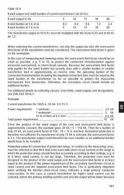
10
467
Table 10-4
Rated output and rated burden of current transformers (at 50 Hz)
Rated output in VA 5 10 15 30 60
Rated burden at 5 A in Ω 0.2 0.4 0.6 1.2 2.4Rated burden at 1 A in Ω 5 10 15 30 60
The transformer output at 16 ²⁄₃ Hz must be multiplied with the factor 0.33 and at 60 Hzby 1.2.
When selecting the current transformers, not only the output but also the overcurrentlimit factor of the transformer must be considered. The overcurrent limit factor is givenon the nameplate.
In the case of measuring and metering cores, the overcurrent limit factor should be assmall as possible, e. g. 5 or 10, to protect the connected instrumentation againstexcessive overcurrents or short-circuit currents. Because the overcurrent limit factoronly applies for the rated burden but actually rises with a smaller burden or smallertransformer load in approximately an inverse ratio, the operating burden of theconnected instrumentation including the required connection lines must be equal to therated burden of the transformer so far as possible to protect the measuringmechanisms from destruction. Otherwise, the secondary circuit should include anadditional burden.
For additional details on selecting classes, error limits, rated outputs and designations,see DIN VDE 0414-1.
Example:
Current transformer for 100/5 A, 30 VA 0.5 FS 5
Power requirement: 1 ammeter ................................................................... 2.5 VA1 wattmeter .................................................................. 3 VA25 m of lines of 2.5 mm2 .............................................. 4.5 VA
Total power requirement ................................................................................... 10 VA
Since the product of the rated output of the core and overcurrent limit factor isapproximately constant, the example gives 30 VA • 5 = 150 VA. Then for a burden ofonly 10 VA, an overcurrent factor of 150 : 10 = 15 is reached. Instrument protection istherefore not sufficient. If a transformer of only 15 VA is selected, the overcurrent factoris 7.5. The transformer output could therefore be even smaller, or an additional burdenwould have to be included.
Protective cores for connection of protection relays, in contrast to the measuring cores,must be selected so that their total error even with short-circuit currents in the range inwhich the protection relays should function accurately according to their settings, e.g. 6to 8 times rated current, is not too large. Therefore, the protective core must bedesigned so the product of the rated output and the overcurrent limit factor is at leastequal to the product of the power requirement of the secondary transformer circuit atrated current and the required overcurrent limit factor. This is particularly importantwhen verifying the thermal short-circuit stress indicates a large primary conductorcross-section. In this case, a current transformer for higher rated current can beselected, where the primary winding number and also the output will be lower because
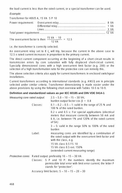
468
the load current is less than the rated current, or a special transformer can be used.
Example:
Transformer for 400/5 A, 15 VA 5 P 10
Power requirement: Overcurrent relay............................................................. 8 VADifferential relay............................................................... 1 VALines................................................................................ 3 VA
Total power requirement ...................................................................................... 12 VA
15 VA · 10The overcurrent factor is then ————––––— = 12.5
12 VA
i.e. the transformer is correctly selected.
An overcurrent relay set to 8 In will trip, because the current in the above case to 12.5 x rated current increases in proportion to the primary current.
The direct current component occurring at the beginning of a short circuit results intransmission errors by core saturation with fully displaced short-circuit current.Specially dimensioned cores with a high overcurrent limit factor (e.g. 200) or theselection of a high transformation ratio for the protective core can remedy this.
The above selection criteria also apply for current transformers in enclosed switchgearinstallations.
Current transformers according to international standards (e.g. ANSI) are in principleselected under similar criteria. Transformer dimensioning is made easier under theabove provisions by using the following short overview with Tables 10-5 to 10-9.
Definition and standardized values as per IEC 60185 and DIN VDE 0414-1
Measuring core rated output: 2.5 – 5.0 – 10 – 15 – 30 VA;burden output factor cos β = 0.8
Classes: 0.1 – 0.2 – 0.5 – 1: valid in the range of 25 % and 100 % of the rated burden.0.2 s and 0.5 s: For special applications (electricalmeters that measure correctly between 50 mA and 6 A, i.e. between 1% and 120% of the rated currentof 5A)3 – 5: valid in the range 50% to 100% of the ratedburden
Label: measuring cores are identified by a combination ofthe rated output with the overcurrent limit factor andwith the class, e.g.15 VA class 0.5 FS 1015 VA class 0.5 ext. 150% (extended current measuring range)
Protective cores Rated output: preferably 10 – 15 – 30 VAClasses: 5 P and 10 P: the numbers identify the maximum
permissible total error with limit error current; the letter Pstands for “protection”.
Accuracy limit factors: 5 – 10 – 15 – 20 – 30
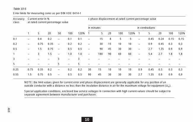
10
469
Table 10-5
Error limits for measuring cores as per DIN VDE 0414-1
Accuracy Current error in % ± phase displacement at rated current percentage valueclass at rated current percentage value
in minutes in centiradians
1 5 20 50 100 120% 1 5 20 100 120% 1 5 20 100 120%
0.1 – 0.4 0.2 – 0.1 0.1 – 15 8 5 5 – 0.45 0.24 0.15 0,15
0.2 – 0.75 0.35 – 0.2 0.2 – 30 15 10 10 – 0.9 0.45 0.3 0,3
0.5 – 1.5 0.75 – 0.5 0.5 – 90 45 30 30 – 2.7 1.35 0.9 0,9
1 – 3 1.5 – 1.0 1.0 – 180 90 60 60 – 5.4 2.7 1.8 1,8
3 – – – 3 – 3 – – – – – – – – – –
5 – – – 5 – 5 – – – – – – – – – –
0.2S 0.75 0.35 0.2 – 0.2 0.2 30 15 10 10 10 0.9 0.45 0.3 0.3 0,3
0.5S 1.5 0.75 0.5 – 0.5 0.5 90 45 30 30 30 2.7 1.35 0.9 0.9 0,9
NOTE: the limit values given for current error and phase displacement are generally applicable for any position of anoutside conductor with a distance no less than the insulation distance in air for the maximum voltage for equipment (Um).
Special application conditions, enclosed low service voltages in connection with high current values should be subject toseparate agreement between manufacturer and purchaser.

470
Table 10-6
Error limits for protective cores as per DIN VDE 0414-1
Accuracy Current error Phase displacement Composite errorclass in % at primary at primary rated in % at
current Rated in in Rated accuracycurrent minutes centiradians limits
5 P + 1 + 60 + 1.8 510 P + 3 – – 10
Table 10-7
Normal burdens (for 5 A – secondary current)
Des. resistance inductance impedance rated power cos βof burden (Ω) (mH) (Ω) (VA)
B-0.1 0.09 0.116 0.1 2.5 0.9B-0.2 0.18 0.232 0.2 5.0 0.9B-0.5 0.45 0.580 0.5 12.5 0.9B-0.9 0.81 1.04 0.9 22.5 0.9B-1.8 1.62 2.08 1.8 45.0 0.9
Table 10-8
Error limits in the range cos β = 0.6 – 1.0
Class Ratio error (factor) + Phase displacement corresp.at rated current at rated current IEC100 % 10 % 100 % 10 % class
min. max. min. max. minutes1) minutes1)
0.3 0.997 1.003 0.994 1.006 16 33 0.20.6 0.994 1.006 0.988 1.012 33 65 0.51.2 0.968 1.012 0.976 1.024 65 130 1
1) approximate values derived from diagram
Definition and standardized values as per ANSI/IEEE – Standard C57.13-1978(based on rated frequency 60 Hz)
Measuring cores Classes: 0.3 – 0.6 – 1.2
Designation: measuring cores are identified by a combination ofthe class with the burden identification, e.g.
0.3 B-0.1 or 0.6 B-0.5

10
471
Protective cores
Table 10-9
Normal burdens: (for 5 A secondary current)1)
Designation Resistance Inductance Impedance Rated power cos βof burden Ω (mH) Ω (VA)
B-1 0.5 2.3 1.0 25 0.5B-2 1.0 4.6 2.0 50 0.5B-4 2.0 9.2 4.0 100 0.5B-8 4.0 18.4 8.0 200 0.5
1) In the case of other secondary currents, the burden values are converted at unchanged rated powerand cos ß
Classes/Error limits
“C” and “T” at max. total error 10% in the range 1–20 x primary rated current(corresponding to IEC Class 10 P 20).
With “C” transformers, the magnetic flux in the transformer core does not influence thetransformation ratio. With “T” transformers, magnetic flux influence at a limited level ispermissible, but must be verified by testing.
Secondary terminal voltage
The transformer must supply this voltage at the rated burden at 20 times the secondaryrated current without exceeding the max. ratio error of 10%.
Sec. terminal voltage Rated burden
(V)100 B-1200 B-2400 B-4800 B-8
Label
Protective cores are identified by class and secondary terminal voltage, e.g. C 100, a C-transformer with secondary terminal voltage 100 V for rated burden B-1.

472
Table 10-10
Testing (100%) of current transformers
Test DIN VDE*) IEC 60185 ANSI C 57.130414-1 (1987) (1978)
1. connection labels × × ×2. insulating capacity/alternating voltage × × ×
test of the primary winding against ground
3. insulating capacity/alternating voltage × × ×test of the secondary windings against one another and against ground
4. winding test × ×5. verification/accuracy × × ×
measurement, current error and phase displacement
6. verification/accuracy measurement, × ×total error with protective cores
7. measurement of the magnetizing current ×with protective cores
8. partial-discharge measurement × ×VDE 0414 IECPart10 60044-4
9. polarity measurement ×
*) largely identical to IEC 60185
10.5.3 Inductive voltage transformers
Inductive voltage transformers are transformers of low output with which the secondaryvoltage is practically proportional to and in phase with the primary voltage. Voltagetransformers are used to transform the system voltage to be measured to a secondaryvoltage to be fed to measuring and protection devices. The primary and secondarywindings are galvanically separated from each other.
Inductive voltage transformers are supplied in the following designs:
1. Two-phase isolated voltage transformers
for connection between two phases, ratio 6000/100 V, for example. Two voltagetransformers in V connection are normally used for measuring power in three-phasenetworks.
Testing (100%) of current transformers
The transformers are subjected to the testing (100%) required under the standardsbefore delivery. Table 10-10 shows an overview of the tests according to DIN VDE, IECand ANSI.

10
473
2. Single-phase isolated voltage transformers
for connection between one phase and ground, ratio110 000 / 3 // 100 / 3 V.Three voltage transformers connected in star are required for measuring power inthree-phase networks. If single-phase isolated voltage transformers have anauxiliary winding for ground-fault monitoring, in three-phase networks, this must bemeasured for the ratio of 100/3 V. The “open delta” in the three-phase set can alsohave a fixed resistance for damping relaxation oscillations (resulting fromferroresonances in insulated networks with small capacitances).
3. Three-phase voltage transformers
with the measuring windings connected in star and an auxiliary winding on the 4th and 5th limb for ground-fault detection. The auxiliary winding has a voltage of100 V in the event of a ground fault.
Inductive voltage transformers are selected by the primary and secondary rated voltageand the accuracy class and rated output of the secondary windings in accordance withthe requirements of the devices to which they are to be connected.
If there is a winding for ground fault detection, its rated thermal limit output must begiven. For the short-time withstand, the rated voltage factor and the specified loadduration at increased voltage are required.
10.5.4 Capacitive voltage transformers
Voltage transformers at higher system voltages to 765 kV that operate under theprinciple of the capacitive voltage divider can also be used. The capacitive voltagetransformers are designed for connection of all standard operational instrumentationand network protection relays; they are also approved for tariff metering.
Fig. 10-28 shows the line diagram of a capacitive voltage transformer. Networkprotection relays with transistorized circuits for the shortest closing times are alsosecurely fed from capacitive transformers, particularly if the transformers have asampling device that damps all transient oscillations of the transformer in the shortesttime.
Capacitive voltage transformers also have the advantage of being usable for couplinghigh-frequency power-line carrier systems, e.g. for telecommunications, remote-controlinstallations and similar purposes. The required supplementary elements (choke, surgearrester) can be installed in terminal boxes.
When selecting capacitive voltage transformers, primary and secondary rated voltage,rated frequency, rated output and class are the essential features. In addition, the ratedthermal limiting output of a ground-fault detector winding, rated voltage factor and thespecified load duration at increased voltage must be considered.

474
Capacitive voltage transformers are selected similarly to the inductive transformers, butthe capacitances of the high-voltage capacitors (C1), of the intermediate-voltagecapacitor (C2) and the rated capacity (Cn) must also be given. A dimensioning examplefor a capacitive voltage transformer is shown below:
Primary rated voltage 110 000V
3
Secondary rated voltage 110 V
of the measuring effect 3
of the winding for the ground fault detection 100 V
3
Rated output 75 VA, Cl. 0.5
Rated voltage factor 1.9 Un, 4h
Thermal rated burden rating 120 VA, 8h
Rated capacity 4.400 pF ± 10 %
Rated frequency 50 Hz
The properties with transient processes are also important with capacitive transformers(interaction with network protection).
SF6-insulated switchgear installations also include inductive and capacitive voltagetransformers, see Section 11.2.
Fig.10-28
Basic diagram of a capacitivevoltage transformer
1 High-voltage terminal, 2 Medium-voltage choke coil, 3 Transformer, 4 Secondaryterminals, 5 Terminal boxtrimming winding, 6 TFHterminal, 7 TFH coupling, 8 Damping device, Cn C1 C2
capacitive voltage divider
10
475
10.5.5 Non-conventional transformers
In contrast to conventional transformers, non-conventional current and voltagetransformers are distinguished by compact size and low weight. They are generally notsaturable and have high transmission bandwidths. The measured values are besttransmitted by fibre-optic cables, which are practically immune to electromagnetic fields(EMC). The non-conventional type of measured value acquisition and transmissionrequires only limited output in the area of 0.1 ... 5 VA on the secondary side.
Non-conventional transformers consist of a measurement recorder, a measured valuetransmission line bridging the potential difference between high voltage and groundpotential and an electronic interface at ground potential for measured-value processingand connections to protection devices in the station control system.
Measurement recorders can be divided into active and passive systems depending onthe method used.
Active non-conventional transformers
Hall-effect elements, Rogowski coils or specially designed bar-type currenttransformers with linear characteristics are used for current detection. Voltageacquisition is generally done using resistive or capacitive voltage dividers. In substationtechnology for rated voltages below 52 kV and also for GIS installations for highervoltages, active non-conventional transformers offer very attractive solutions.
However, in outdoor substation technology for transmission networks, the electricalmeasured quantities must still be converted to a digital or analogue optical signal athigh-voltage potential. This requires devices for providing the required auxiliary energyat high-voltage potential. This energy requirement may be taken from the high-voltagesystem that is being monitored and also provided by optical means, whether by solarcell or by energy transmission via fibre-optic lines.
Passive non-conventional transformers
Passive measurement recorders do not require auxiliary energy at high-voltagepotential. They are normally completely constructed of dielectric materials.
Passive optical voltage transformers
Linear electro-optic effects (Pockel effect) linked to specific classes of crystals are usedfor voltage measurement with optical voltage transformers. The physical principle of thePockel effect is a change of the polarization state of light that is sent within an electricalfield through a transparent material. The change in polarization is linearly proportionalto the applied electrical field.

476
In the ABB-developed EOVT (electro optical voltage transducer) the Pockel cell, a BGOcrystal (Bi12GeO20) is installed directly between the high voltage electrode and groundwith the light path parallel to the electrical field (Fig. 10-29).
BGO-Kristall
Lichtsignal(Eingang)
Erdpotential
Hochspannung
Lichtsignale(Ausgang)
Fig.10-29
Principle of the light circuit in a crystal (BGO) for passive optical voltage measurementusing the Pockel effect
The monochromatic polarized light beam entering at ground potential in the end face ofthe crystal is reflected at the prismatic end of the crystal at high-voltage potential so thedielectrically stressed range is run through twice by light. This doubles the polaritychange caused by the electrical field. The light beam exiting the end face is split intotwo directional components by an optical system. These are transmitted to thephotodiodes by fibre-optic cables. They indicate the phase difference (polarizationchange) arising in the dielectric field from the intensities of the two components andtherefore a scale for the applied voltage. The use of two light signals at the output hasthe advantage of providing an accurate measurement result in spite of relatively smalloutput signals and parasitic effects (phase change by temperature influence andnatural double refraction properties of the crystal) are eliminated.
The EOVT was designed from the outset for voltage levels to at least 420 kV.Therefore, the BGO crystal is basically surrounded by an SF6 atmosphere. Fig. 10-30shows the EOVT in an enclosed SF6-insulated switchgear installation for 123 kV. TheBGO crystal is surrounded by a glass tube between two field-control electrodes, thelower at high-voltage potential and the upper at ground potential. The monochromaticlight feed and the return line of the subcomponents after the polarization change isthrough fibre-optic cables, which feed through the grounded installation enclosure tothe processing device.
BGO crystal
high voltage
light signals(input)
light signals(output)
ground

10
477
For applications in outdoor installations, the active component of the EOVT, as shownin Fig. 10-33 as a combination solution with a current transformer, is installed inside anappropriate SF6-filled composite insulator. The technical data of the EOVT opticalvoltage transformer is shown in Table 10-11.
Fig.10-30
View of a voltage transformer (EOVT) for a gas-insulated switchgear installation (GIS).The transformers for two phases of a GIS bay.
Steuerelektroden
BGO-Kristall
SF6-Kammer
GIS-Feldverbindung
Passive optical current transformer
An optical current transformer like the ABB-developed MOCT (magneto optical currenttransducer) uses the Faraday effect in crystalline structures for passive measurementof currents. Again monochromatic light is sent polarized into a solid body of glass,which surrounds the current carrying conductor. Reflection from the bevelled corners ofthe glass container directs the light beam around the conducting line before it exitsagain on one side (Fig. 10-31).
The magnetic field around the conductor rotates the polarization plane of the light,whose phase difference is proportional to the magnetic field intensity H. Because thelight in the glass body completely surrounds the current path as a line integral along aclosed curve, the phase difference at the end of the path in the glass body is directlyproportional to the current. A polarization filter at the exit point of the light from the glassbody only allows one subcomponent of the light generated by the rotation to pass. It isfed to the processing unit through fibre-optic cables. The intensity of this subcomponentis the scale for the polarization change and so for the magnitude of the current.
SF6 chamber
GIS bay connection
control electrodes
BGO crystal

478
The technical data of the MOCT optical current transformer are summarized in Table 10-12. Its low space requirements and low weight (Fig. 10-32) provide newoptions in the design of outdoor switchgear installations, such as by a (alreadyimplemented) combination of circuit-breaker and MOCT. In addition, the combinedsolution of EOVT and MOCT shown in Fig. 10-33 is distinguished on one hand by theenvironmental aspect – no danger of contamination by leaking oil – and on the otherhand by a substantial reduction in weight compared to conventional solutions.
Connection to protection technology
Devices and systems in conventional secondary technology are generally directlylinked to the primary quantity with standardized current and voltage ports (typically 100 V or 1 A). The former specification of these ports is based on the requirements ofanalogue secondary devices with high power requirements and the attempt to attainsecurity with reference to electromagnetic influence by relatively high signal levels.
However, modern secondary devices, in general digital, only require a small part of theinput power that was formerly required (typically 0.1 VA to 1 VA).
Legende 1 Analysator
2 Lichtweg im Sensor
3 Polarisator
4 Primärleiter
5 Faraday-Sensor
6 Linse
7 Lichtwellenleiter
8 Detektor
9 Lichtquelle
Fig.10-31
Passive non-conventional current transformer (MOCT). The Faraday sensor aroundthe conductor line is structured as a glass block.
Legend
1 Analyzer
2 Light path in sensor
3 Polarizer
4 Primary conductor
5 Faraday sensor
6 Lens
7 fibre-optic cable
8 Detector
9 Light source

10
479
In non-conventional metering transformers, the processing device sends a small signalthat is generally suitable for digital secondary devices. However, if necessary,supplementary amplifier inserts can generate current and voltage signals suitable forthe interfaces of conventional secondary technology.
Fig.10-32
Comparison of a non-conventional current transformer (left in the picture) with aconventional outdoor transformer with paper-oil insulation
fibre-optic cable
Conventionalcurrenttransformer
Passive opticalcurrent transformer(MOCT)
Insulator forconducting thefibre-optic cable
fibre-optic cable
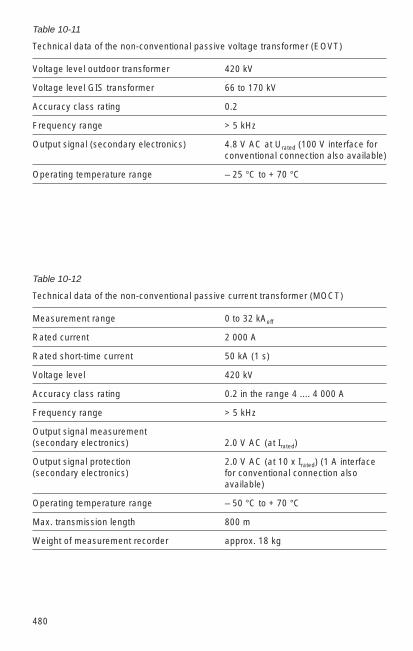
480
Table 10-11
Technical data of the non-conventional passive voltage transformer (EOVT)
Voltage level outdoor transformer 420 kV
Voltage level GIS transformer 66 to 170 kV
Accuracy class rating 0.2
Frequency range > 5 kHz
Output signal (secondary electronics) 4.8 V AC at Urated (100 V interface forconventional connection also available)
Operating temperature range – 25 °C to + 70 °C
Table 10-12
Technical data of the non-conventional passive current transformer (MOCT)
Measurement range 0 to 32 kAeff
Rated current 2 000 A
Rated short-time current 50 kA (1 s)
Voltage level 420 kV
Accuracy class rating 0.2 in the range 4 .... 4 000 A
Frequency range > 5 kHz
Output signal measurement (secondary electronics) 2.0 V AC (at Irated)
Output signal protection 2.0 V AC (at 10 x Irated) (1 A interface(secondary electronics) for conventional connection also
available)
Operating temperature range – 50 °C to + 70 °C
Max. transmission length 800 m
Weight of measurement recorder approx. 18 kg
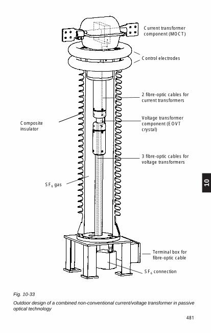
10
481
Stromwandlerteil(MOCT)
Steuerelektroden
Spannungswandlerteil(EOVT- Kristall)
Anschlußkasten fürLichtwellenleiter
Verbundisolator
2 Lichtwellenleiterfür Stromwandler
3 Lichtwellenleiter fürSpannungswandler
.
SF6 - Gas
SF6-Anschluß
Fig. 10-33
Outdoor design of a combined non-conventional current/voltage transformer in passiveoptical technology
Current transformercomponent (MOCT)
Control electrodes
2 fibre-optic cables forcurrent transformers
Voltage transformercomponent (EOVTcrystal)
3 fibre-optic cables forvoltage transformers
Terminal box forfibre-optic cable
SF6 connection
Compositeinsulator
SF6 gas

482
10.6 Surge arresters
10.6.1 Design, operating principle
The operation and design of the surge arrester has radically changed over the lasttwenty years.
Arresters with spark gap with series-connected silicon carbide (SiC) resistors havebeen replaced by surge arrester technology without spark gap and with metal-oxideresistors. The former porcelain housing is also being replaced more and more bypolymer insulation. DIN EN 60 099-4 (VDE 0675 Part 4) contains detailed informationon the new arrester technology.
The gapless arresters are based on metal oxide (MO) resistors, which have anextremely non-linear U/I characteristic and a high energy-absorption capability. Theyare known as metal oxide surge arresters, MO arresters for short.
The MO arrester is characterized electrically by a current/voltage curve (Fig. 10-34).The current range is specified from the continuous operating range (range A of thecurve, order of magnitude 10-3 A) to a minimum of the double value of the rateddischarge current (order of magnitude 103 A). The MO arrester corresponding to thecharacteristic is transferred from the high-resistance to the low-resistance range atrising voltage without delay. When the voltage returns to the continuous operatingvoltage Uc or below, the arrester again becomes high-ohmic.
The protective level of the MO arrester is set by its residual voltage UP. The residualvoltage is defined as the peak value of the voltage at the terminals of the arrester whena surge current flows. A surge current with a front time of about 1 µs, a time to half-value of up to 10 µs and a current of up to 10 kA represents very steep overvoltagewaves, and the associated residual voltage is comparable to the front sparkovervoltage of spark-gapped arresters.
Fig. 10-34
Current-voltage characteristic of a metal oxide resistor; a Lower linear part, b Kneepoint, c Strongly non-linear part, d Upper linear part (“turn up” area), A Operating point(continuous persistent voltage)

10
483
A surge current with a front time of about 8 µs and a current intensity of up to10 kA yields a residual voltage that is approximately equal to the protection level withlightning surge voltage. The current wave with a front time between 30 µs and 100 µscorresponds to a switching voltage pulse. The residual voltage with this wave form at 1 kA yields the protection level for switching voltages.
Surge arresters are protective devices that may be overloaded under extreme faultconditions. In such cases, e.g. when voltage leaks from one network level to the other,a single-phase earth fault occurs in the resistor assembly of the arrester. The pressurerelief ensures that porcelain housings do not explode. The earth-fault current of thenetwork at the arrester site must be less than the guaranteed current for the pressurerelief of the relevant arrester. Fig. 10-35 shows the structural design of an MO arresterwith a polymer housing.
Today, MO arresters for protection of medium-voltage equipment almost always havecomposite housings of silicon polymer. This insulation material allows the metal oxideresistors to be directly surrounded without gas inclusions. This type, in contrast toarresters with porcelain or other tube material, does not require a pressure-relief devicefor a possible overload. Because the polymeric arresters are substantially lighter, havea better response under contamination layer conditions and the arrester cannot fallapart in the event of an overload, this new technology is becoming more and morecommon even for arresters for high voltage.
Fig.10-35
Cutaway view (principledesign) of a metal oxide surgearrester, type POLIM-H

484
Fig.10-36
Arrester selection for a low-resistanceearthed network (cE = 1,4) in range II (Um
≥ 245 kV) as per DIN EN 600099-5 (VDE0675 Part 5)a maximum power frequency
conductor-ground voltage in thenormally operating network (1 p.u. = peak value)
b peak value of the maximumtemporary power frequencyconductor-ground voltage at earthfault in an adjacent phase
cE earth fault factor (= 1.4)d switching impulse overvoltage
(limited by arrester to Ups)Ups switching impulse protection level of
the arresterUwL rated lightning impulse voltage for
equipment-standardized valuesUwS rated switching impulse voltage for
equipment-standardized values
10.6.2 Application and selection of MO surge arresters
Surge arresters are used for protection of important equipment, particularlytransformers, from atmospheric overvoltages and switching overvoltages. MO arrestersare primarily selected on the basis of two basic requirements:– the arrester must be designed for stable continuous operation,– it must provide sufficient protection for the protected equipment.
Stable continuous operation means that the arrester is electrically and mechanicallydesigned for all load cases that occur under standard operation and when system faultsoccur. This requires that the electrical and mechanical requirements are known asprecisely as possible. The magnitude of the maximum power-frequency voltage,magnitude and duration of the temporary overvoltages and the anticipated stressescaused by switching and lightning overvoltages must all be known. In addition, thestress caused by short-circuit current forces and special environmental conditions, e.g.pollution, ambient temperatures over 45 °C, installation in earthquake regions etc., arevery important.
When selecting the arrester by its electrical data, there must be an appropriate marginbetween the protection level of the arrester and the insulation levels standardized forthe applicable operating voltage to meet the requirements of the insulation coordinationas per DIN EN 60 071-1 (VDE 0111 Part 1) (Fig. 10-36).
Parallel connecting of MO resistor columns allows every technically necessarydimension of the energy-absorption capability to be implemented at equivalentprotection levels. Doubling the number of columns can reduce the protection level andalmost double the energy-absorption capability.
DIN EN 60099-5 (VDE 0675 Part 5) outlines the correct selection of MO arresters.
p.u.
4U
3
2
1
Uwl
Uws
b
a
Ups
t
d
cE
CB, CS safety margins

10
485
For MO arresters, the continuous operating voltage Uc is defined as the maximumpower frequency voltage that the arrester can withstand continuously. The peak valueof the continuous operating voltage of the arrester must be higher than the peak valueof the operating voltage. On one hand, it is determined by the power-frequency voltagethat corresponds to the maximum voltage in the network; but on the other hand,possible harmonics of the voltage must be considered. In normal networks, a safetymargin of 5% over the power frequency system voltage is sufficient.
The rated voltage Ur of an MO arrester is the reference value to the power frequencyvoltage versus time characteristic and is decisive for the selection of the arrester withreference to temporary overvoltages. During the operating duty test of an MO arrestertype, a test voltage of Ur is applied immediately following the surge current for a periodof 10 s to the test object.
Ur is the 10 s value in the power frequency voltage versus time characteristic of thearrester. Peak values of the permissible power-frequency alternating voltage for otherperiods (Ut , Tt ) are taken from the characteristic submitted by the manufacturer orderived approximately for period Tt in s between 0.1 s and 100 s by calculation as in thefollowing equation:
10 m
Ut = 2 Ur (——)Tt
m = arrester-specific exponent, average value 0.02Possible causes of the occurrence of temporary overvoltages include– Earth fault– Load shedding– Resonance phenomena and– Voltage increases over long lines
The following selection recommendations can be formulated based on the neutraltreatment in networks:
Arresters between line and earth– In networks with automatic earth-fault interruption, the continuous operating voltage
Uc of the arrester should be equal to or greater than the peak value of the maximumoperating voltage of the network against ground divided by 2
– In networks with earth-fault neutralizing or isolated neutral point without automaticfault disconnection, the continuous operating voltage should be greater than or atleast equal to the maximum operating voltage of the network.
Arresters between phases– The continuous operating voltage must be at least 1.05 times the maximum service
voltage.
Neutral-point arresters– For networks with low-resistance neutral-point configuration, the continuous
operating voltage Uc of the arresters is derived from the dielectric strength specifiedfor the neutral point of the equipment.
– For networks with earth-fault compensation or with insulated neutral point, thecontinuous operating voltage should be at least equal to the maximum servicevoltage divided by 3

486
Table 10-13 shows recommended standard values for selecting MO arresters (underthe asumption that no additional temporary overvoltages occur) for some currentnominal system voltages and the earth-fault factors appearing there.
Table 10-13
Recommended values for MO arresters according to the continuous operating voltageUc and the associated rated voltage Ur
Nominal Phase arrester Neutral-point arrestersystem at CE = 1.4 at CE = 3 at CE = 1.4 at CE = 3voltage Uc Ur Uc Ur Uc Ur Uc Ur
kV kV kV kV kV kV kV kV kV
6 – – 7,2 9 – – > 4,7 > 5,9 10 – – 12 15 – – > 7,8 > 9,75 20 – – 24 30 – – > 15,6 > 12,5 30 – – 36 45 – – > 23,4 > 29,3
110 75 126 1231) 1441) 50 78 72 84 220 160 2162) – – 60 108 – – 380 260 3602) – – 110 168 – –
1) Lower values are possible if the duration of the earth fault is accurately known.2) Higher values are set for generator transformers.
After specifying the continuous operating voltage and the rated voltage of the arresterthat is to be used, selection is based on the energy-absorption capability required bythe system conditions (rated discharge current and line discharge class). The followingselection recommendation for rated discharge current can be set as a generalguideline:
Distribution networks of up to 52 kV– sufficient under standard conditions 5 kA– at higher lightning intensity, cable units,
capacitors, specially important analogues 10 kA– specially high lightning loads 20 kA
Transmission networks of up to 420 kV 10 kATransmission networks over 420 kV 20 kA
In specially supported cases, it may be necessary to determine the required energy-absorption capability more accurately, e.g. as follows– Closing or reclosing long lines,– Switching capacitors or cables with non-restrike-free switching devices,– Lightning strikes in overhead lines with high insulation level or back flashovers near
the installation site.
If the calculated energy content exceeds the energy quantity absorbed at the duty testof the arresters, an arrester with higher rated discharge current or parallel connectedarresters must be selected.

10
487
Surge arresters are preferably installed parallel to the object to be protected betweenphase and earth. Because of the limited protection distance with steep lightningimpulse voltages, the arresters must be installed immediately adjacent to theequipment that is to be protected (e.g. transformer) as much as possible. The size ofthe protection distance of an arrester is dependent on a whole series of influencingparameters. It increases as follows:– the difference between rated lightning impulse voltage of the equipment and the
protection level (Upl) of the arrester,– the limitation of the peak value of the incoming lightning surge voltage wave by the
mast type of the overhead line before the substation (e.g. grounded cross-arms ortimber masts),
but also from the point of view of the insulation coordination with
– the decrease of the lightning strike rate of the overhead line (e.g. shielding byoverhead ground wire) and with
– the increase of the fault rate that is still considered acceptable for the equipment thatmust be estimated.
Examples for the size of protection ranges in outdoor switchgear installations forvarious rated system voltages under practice-relevant conditions are shown in Table 10-14. Permissible fault rates of 0.25% per year for the equipment and lightningstrike rates of 6 per 100 km x year for the 24 kV overhead lines and of 2 per 100 km xyear for the high-voltage lines are assumed.
Table 10-14
Guidance values for the protection range of MO arresters
Network Arrester Rated lightning Protection nominal voltage protection level impulse withstand distance
voltagekV kV kV m
24 80 125 31)/152)
123 350 550 24420 900 1425 32
1) Overhead line with timber masts (without grounding)2) Overhead line with grounded cross-arms
The ABB travelling wave program for testing larger switchgear installations can be usedto calculate the temporal course of the voltage at all interesting points of the installation.
In overhead lines with cable feed, the travelling wave through the cable withovervoltages must be calculated by reflection in spite of the depression. Arrester A1 isto be provided for protection of the cable in short cable units (lk ≤ 5 m) and arrester A3for protection of the transformer, see fig. 10-37. however, if lk > 5 m, the cable must beprotected on both sides with arresters A1 and A2. In this case, arrester A3 can only beomitted with the transformer if the protection range of arrester A2 is greater thanl1.

488
Fig.10-37
Overvoltage protection of the cable link of overhead lines, lK: length of cable unit, l1: distance cable / transformer, A1 & A2 arresters for protection of the cable, A3 arrester for protection of the transformer
Cable units within an overhead line should be protected immediately adjacent to thetwo end seals with arresters.
Surge counters may be used to monitor surge arresters. They are installed in theground conductor of the arrester that is to be monitored; the arresters must be installedinsulated against ground.
lk l1

11
489
11 High-Voltage Switchgear Installations
11.1 Summary and circuit configuration
11.1.1 Summary
A switchgear installation contains all the apparatus and auxiliary equipment necessaryto ensure reliable operation of the installation and a secure supply of electricity. Three-phase a.c. high-voltage switchgear installations with operating voltages of up to 800 kVare used for distributing electricity in towns and cities, regions and industrial centres,and also for power transmission. The voltage level employed is determined by thetransmission capacity and the short-circuit capacity of the power system.
Distribution networks are operated predominantly up to 123 kV. Power transmissionsystems and ring mains round urban areas operate with 123, 245 or 420 kV, dependingon local conditions. Over very large distances, extra high powers are also transmittedat 765 kV or by high-voltage direct-current systems.
Switchgear installations can be placed indoors or outdoors. SF6 gas-insulatedswitching stations have the important advantage of taking up little space and beingunaffected by pollution and environmental factors.
Indoor installations are built both with SF6 gas-insulated equipment for all voltageratings above 36 kV and also with conventional, open equipment up to 123 kV. SF6
technology, requiring very little floor area and building volume, is particularly suitable forsupplying load centres for cities and industrial complexes. This kind of equipment isalso applied in underground installations.
Outdoor switching stations are used for all voltage levels from 52 to 765 kV. They arebuilt outside cities, usually at points along the cross-country lines of bulk transmissionsystems. Switchgear for HVDC applications is also predominantly of the outdoor type.
Transformer stations comprise not only the h.v. equipment and power transformers butalso medium- and low-voltage switchgear and a variety of auxiliary services. Thesemust additionally be accounted for in the station layout.
Depending on the intended plant site, the construction of a switchgear installation mustconform to IEC requirements, VDE specifications (DIN VDE 0101) or particular nationalcodes.
The starting point for planning a switchgear installation is its single-line diagram. Thisindicates the extent of the installation, such as the number of busbars and branches,and also their associated apparatus. The most common circuit configurations of highand medium-voltage switchgear installations are shown in the form of single-linediagrams in Section 11.12.
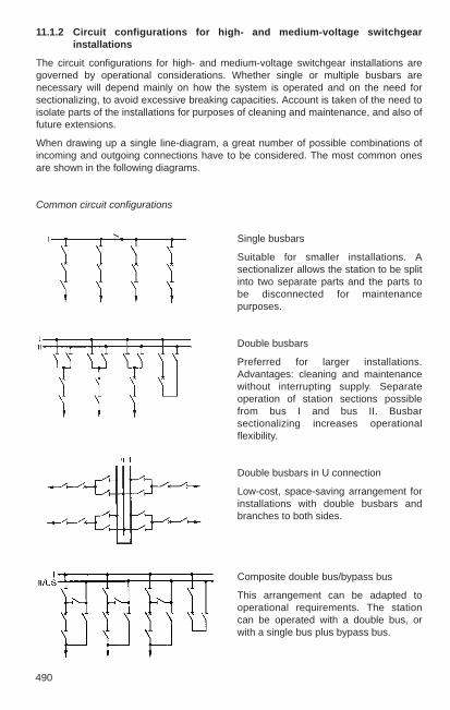
490
11.1.2 Circuit configurations for high- and medium-voltage switchgearinstallations
The circuit configurations for high- and medium-voltage switchgear installations aregoverned by operational considerations. Whether single or multiple busbars arenecessary will depend mainly on how the system is operated and on the need forsectionalizing, to avoid excessive breaking capacities. Account is taken of the need toisolate parts of the installations for purposes of cleaning and maintenance, and also offuture extensions.
When drawing up a single line-diagram, a great number of possible combinations ofincoming and outgoing connections have to be considered. The most common onesare shown in the following diagrams.
Common circuit configurations
Composite double bus/bypass bus
This arrangement can be adapted tooperational requirements. The stationcan be operated with a double bus, orwith a single bus plus bypass bus.
Single busbars
Suitable for smaller installations. Asectionalizer allows the station to be splitinto two separate parts and the parts tobe disconnected for maintenancepurposes.
Double busbars
Preferred for larger installations.Advantages: cleaning and maintenancewithout interrupting supply. Separateoperation of station sections possiblefrom bus I and bus II. Busbarsectionalizing increases operationalflexibility.
Double busbars in U connection
Low-cost, space-saving arrangement forinstallations with double busbars andbranches to both sides.

11
491
Double busbars with draw-out circuit-breaker
In medium-voltage stations, draw-outbreakers reduce downtime whenservicing the switchgear; also, a feederisolator is eliminated.
Triple (multiple) busbars
For vital installations feeding electricallyseparate networks or if rapidsectionalizing is required in the event of afault to limit the short-circuit power. Thislayout is frequently provided with abypass bus.
Double busbars with bypass busbar (US)
The bypass bus is an additional busbarconnected via the bypass branch.Advantage: each branch of theinstallation can be isolated formaintenance without interrupting supply.
Two-breaker method with draw-outcircuit-breakers
Draw-out circuit-breakers result ineconomical medium-voltage stations.There are no busbar isolators or feederisolators. For station operation, thedraw-out breaker can be inserted in acubicle for either bus I or bus II.

492
Double busbars with shunt disconnector
Shunt disconnector “U” can disconnecteach branch without supply interruption.In shunt operation, the tie breaker acts asthe branch circuit-breaker.
Two-breaker method with fixedswitchgear
Circuit-breaker, branch disconnector andinstrument transformers are duplicated ineach branch. Busbar interchange andisolation of one bus is possible, onebranch breaker can be taken out formaintenance at any time withoutinterrupting operation.
Special configurations, mainly outside Europe
1 ¹₂-breaker method
Fewer circuit-breakers are needed for thesame flexibility as above. Isolationwithout interruption. All breakers arenormally closed. Uninterrupted supply isthus maintained even if one busbar fails.The branches can be through-connectedby means of linking breaker V.
Cross-tie method
With cross-tie disconnector “DT”, thepower of line A can be switched to branchA1, bypassing the busbar. The busbarsare then accessible for maintenance.
Ring busbars
Each branch requires only one circuit-breaker, and yet each breaker can beisolated without interrupting the powersupply in the outgoing feeders. The ringbusbar layout is often used as the firststage of 1 ¹₂-breaker configurations.

11
493
H connection with H connection with H connection with 3circuit-breakers switch-disconnectors transformers
A and B = Main transformer station, C = Load-centre substation with circuit-breaker orswitch disconnector. The use of switch-disconnectors instead of circuit-breakersimposes operational restrictions.
Switch-disconnectors are frequently used in load-centre substations for the feeders tooverhead lines, cables or transformers. Their use is determined by the operatingconditions and economic considerations.
Configurations for load-centre substations
Ring main cable connec- Simple ring main cable Cable looption allowing isolation in connectionall directions
Single-feed Double-feed Ring stationsstation station
A B
C C C
A B A B
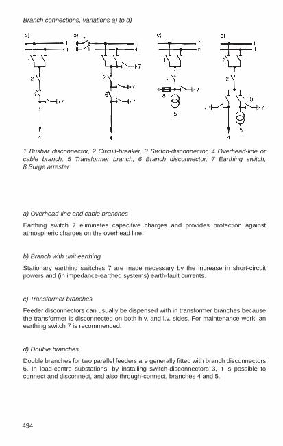
494
a) Overhead-line and cable branches
Earthing switch 7 eliminates capacitive charges and provides protection againstatmospheric charges on the overhead line.
b) Branch with unit earthing
Stationary earthing switches 7 are made necessary by the increase in short-circuitpowers and (in impedance-earthed systems) earth-fault currents.
c) Transformer branches
Feeder disconnectors can usually be dispensed with in transformer branches becausethe transformer is disconnected on both h.v. and l.v. sides. For maintenance work, anearthing switch 7 is recommended.
d) Double branches
Double branches for two parallel feeders are generally fitted with branch disconnectors6. In load-centre substations, by installing switch-disconnectors 3, it is possible toconnect and disconnect, and also through-connect, branches 4 and 5.
Branch connections, variations a) to d)
1 Busbar disconnector, 2 Circuit-breaker, 3 Switch-disconnector, 4 Overhead-line orcable branch, 5 Transformer branch, 6 Branch disconnector, 7 Earthing switch, 8 Surge arrester
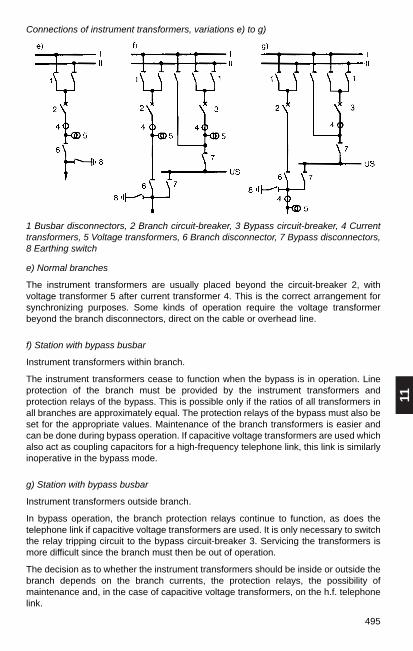
11
495
Connections of instrument transformers, variations e) to g)
e) Normal branches
The instrument transformers are usually placed beyond the circuit-breaker 2, withvoltage transformer 5 after current transformer 4. This is the correct arrangement forsynchronizing purposes. Some kinds of operation require the voltage transformerbeyond the branch disconnectors, direct on the cable or overhead line.
f) Station with bypass busbar
Instrument transformers within branch.
The instrument transformers cease to function when the bypass is in operation. Lineprotection of the branch must be provided by the instrument transformers andprotection relays of the bypass. This is possible only if the ratios of all transformers inall branches are approximately equal. The protection relays of the bypass must also beset for the appropriate values. Maintenance of the branch transformers is easier andcan be done during bypass operation. If capacitive voltage transformers are used whichalso act as coupling capacitors for a high-frequency telephone link, this link is similarlyinoperative in the bypass mode.
g) Station with bypass busbar
Instrument transformers outside branch.
In bypass operation, the branch protection relays continue to function, as does thetelephone link if capacitive voltage transformers are used. It is only necessary to switchthe relay tripping circuit to the bypass circuit-breaker 3. Servicing the transformers ismore difficult since the branch must then be out of operation.
The decision as to whether the instrument transformers should be inside or outside thebranch depends on the branch currents, the protection relays, the possibility ofmaintenance and, in the case of capacitive voltage transformers, on the h.f. telephonelink.
1 Busbar disconnectors, 2 Branch circuit-breaker, 3 Bypass circuit-breaker, 4 Currenttransformers, 5 Voltage transformers, 6 Branch disconnector, 7 Bypass disconnectors,8 Earthing switch

496
Bus coupling SSl/ll Section coupling for A-B 13-tie couplingBypass (US) coupling Bus coupling SSl/ll via Most flexible method ofSSI or II to bypass LTr Bypass coupling A section, bus and bypass
direct, B via LTr to couplingbypass
Busbar coupling connections
A and B = Busbar sections, LTr = Busbar sectioning disconnector
In the configurations earlier in this chapter, the tie-breaker branches are shown in asimple form. Experience shows, however, that more complex coupling arrangementsare usually needed in order to meet practical requirements concerning security ofsupply and the necessary flexibility when switching over or disconnecting. This greatercomplexity is evident in the layouts for medium- and high-voltage installations.
Division into two bays is generally required in order to accommodate the equipment forthese tie-breaker branches.
Double busbars
Bus coupling SSl/II Section coupling for A-B 6-tie couplingfor A or B Bus coupling SSl/ll via Section coupling for
disconnector LTr A-B Buscoupling SSI/II for A or B
Section coupling for A-B 8-tie couplingBus coupling SSl/ll for Section coupling forA or B via tie-breaker A-B Bus coupling SSI/IIbus ll for A or B

11
497
Bus coupling SSI/II/III for A or B Section coupling for A-B, Bypass coupling SSI/II/III Bus coupling SSI/II/III via LTr, to bypass (US) for A or B Bypass coupling A SSI/II/III
to bypass,Bypass coupling B/ bypass via LTr
Triple busbars
Bus coupling SSI/II/III Section- and bus couplingfor all possible ties between the 6 sections A-B
11.2 SF6 gas-insulated switchgear (GIS)
11.2.1 General
The range of application of SF6 gas-insulated switchgear extends from voltage ratingsof 72.5 up to 800 kV with breaking currents of up to 63 kA, and in special cases up to 80 kA. Both small transformer substations and large load-centre substations can bedesigned with GIS technology.
The distinctive advantages of SF6 gas-insulated switchgear are: compact, low weight,high reliability, safety against touch contact, low maintenance and long life. Extensivein-plant preassembly and testing of large units and complete bays reduces assemblyand commissioning time on the construction site.
GIS equipment is usually of modular construction. All components such as busbars,disconnectors, circuit-breakers, instrument transformers, cable terminations and jointsare contained in earthed enclosures filled with sulphur hexafluoride gas (SF6).
The “User Guide for the application of GIS” issued by CIGRÈ WG 23-10 includescomprehensive application information.
Up to ratings of 170 kV, the three phases of GIS are generally in a common enclosure,at higher voltages the phases are segregated. The encapsulation consists of non-magnetic and corrosion-resistant cast aluminium or welded aluminium sheet.
Table 11-1 shows an overview of the various sizes.
IIIIII
IIIIII
IIIIII
IIIIII
US US
A B
A B A LTr B

498
Table 11-1
Rating data and dimensions of the GIS range from 72.5 to 800 kV
Range EXK-01 ELK-04 ELK-14 ELK-34 ELK-4
Service voltage in kV 72.5 – 123 145 – 170 245 – 300 362 – 550 800Lightning impulse voltage 550 750 1050 1550 2000Breaking current in kA 40 40 – 50 40 – 63 40– 63 40 – 50Load current in A 2 500 3150 4000 6300 6300
Bay width in m 0.8/1.0 1.2 1.7 2.7 4.5Bay height in m 2.3 3.0 3.5 4.8 7.5Bay depth in m 3.2 4.6 5.1 6.0 8.0Bay weight in t 2.5 3.7 7.0 11.0 14.0
11.2.2 SF6 gas as insulating and arc-quenching medium
Sulphur hexafluoride gas (SF6) is employed as insulation in all parts of the installation,and in the circuit-breaker also for arc-quenching. SF6 is an electronegative gas, itsdielectric strength at atmospheric pressure is approximately three times that of air. It isincombustible, non-toxic, odourless, chemically inert with arc-quenching properties 3 to4 times better than air at the same pressure, see also Section 10.4.4.
Commercially available SF6 is not dangerous, and so is not subject to the HazardousSubstances Order or Technical Regulations on Hazardous Substances (TRGS). NewSF6 gas must comply with IEC 60376 (VDE 0373 Part 1). Gas returned from SF6
installations and apparatus is dealt with in IEC 60480 (VDE 0373 Part 2). SF6 releasedinto the atmosphere is considered a greenhouse gas. With its contribution to thegreenhouse effect below 0.1%, the proportion of SF6 is low compared to that of thebetter known greenhouse gases (carbondioxide, methane, nitrous oxide etc.). To preventany increase of SF6 in the atmosphere, its useshould in future be confined to closed systems.Devices suitable for processing and storing SF6
gas are available for this purpose. The gaspressure is monitored in the individually sealedgas compartments and in the circuit-breakerhousing. The low gas losses (below 1 % peryear) are taken into account with the first gasfilling. Automatic make-up facilities are notnecessary.
The isolating gas pressure is generally 350 to450 kPa at 20 °C. In some cases this can be upto 600 kPa. The quenching gas pressure is 600to 700 kPa. Outdoor apparatus exposed to arcticconditions contains a mixture of SF6 and N2, toprevent the gas from liquefying. Thepressure-temperature relationship ofpure SF6 gas is shown in Fig. 11-1.
Fig. 11-1
p/t diagram of pure SF6 gas
pressure 102 kPa density kg/m3
temperature

11
499
Fig. 11-2
Conversion of water vapour contentinto dewpoint
Arcing causes the decomposition of very small amounts of SF6 gas. The decompositionproducts react with water, therefore the gas’s moisture content, particularly in thecircuit-breaker, is controlled by drying (molecular) filters. Careful evacuation before firstgas filling greatly reduces the initial moisture content. Fig. 11-2 illustrates theconversion of water vapour content into dewpoint, see also Section 15.5.2.
11.2.3 GIS for 72.5 to 800 kV
SF6 switchgear type EXK/ELK
For voltages from 72.5 to 800 kV ABB has five graduated module sizes of the samebasic design available. The modular construction offers the advantages of quantityproduction, standard components, simple stocking of spares and uniform performance.By combining the various components of a module size, it is possible to assembleswitching installations for all the basic circuit configurations in Section 11.1.2.They arethus able to meet every layout requirement.
As a general recommendation, the intended location for totally enclosed equipmentshould comply with the requirements of DIN VDE 0101 for indoor switchgearinstallations. The buildings can be of lightweight construction, affording some protectionagainst the outdoor elements. With minor modifications, GIS apparatus can also beinstalled outdoors.
500
Components
The busbars are segregated by barrier insulators at each bay and form a unit with thebusbar disconnectors and the maintenance earthing switches.
The circuit-breaker operates on the self-blast principle. Conventional puffer-typebreakers use the mechanical energy of the actuator to generate the breaker gas streamwhile the self-blast breaker uses the thermal energy of the short-circuit arc for thispurpose. This saves up to 80% of the actuation energy. Depending on their size, thebreakers have one to four breaker gaps per pole. They have single- or triple-poleactuation with hydraulic spring mechanisms, see also Section 10.4.4 and 10.4.5.
Switch-disconnectors are used in smaller distribution substations. These are able toswitch load currents and connect and disconnect transformers as well as unloadedlines and cables. They are able to close onto short-circuit currents and carry them for ashort time. They also work on the single-pressure puffer principle and have a motor-driven spring operating mechanism.
The current transformers for measuring and protection purposes are of the toroidal-core type and can be arranged before or after the circuit-breaker, depending on theprotection concept. Primary insulation is provided by SF6 gas, so it is resistant toageing. Iron-free current transformers using the Rogowski coil principle are used withSMART-GIS. They allow quantized evaluation of short-circuit currents and so make itpossible to create a contact erosion image of the circuit-breaker.
Voltage transformers for measurement and protection can be equipped on thesecondary side with two measuring windings and an open delta winding for detectingearth faults.
Inductive voltage transformers are contained in a housing filled with SF6 gas. Foil-insulated voltage transformers are used, with SF6 as the main insulation.
Capacitive voltage transformers can also be employed, usually for voltages above300 kV. The high-voltage capacitor is oil-insulated and contained in a housing filled withSF6 gas. The low-voltage capacitors and the inductive matching devices are placed ina separate container on earth potential. Capacitive tappings in conjunction withelectronic measuring amplifiers are also available.
Electro-optical voltage transformers using the Pockels principle are also used withSMART-GIS.
The cable sealing end can accommodate any kind of high voltage cable with conductorcross-sections up to 2000 mm2. Isolating contacts and connection facilities areprovided for testing the cables with d.c. voltage. If there is a branch disconnector, it issufficient to open this during testing.
Plug-in cable sealing ends for cross-linked polyethylene cables are available forvoltages of up to 170 kV. They consist of gas-tight plug-in sockets, which are installedin the switchgear installation, and prefabricated plugs with grading elements of siliconerubber. Plug-in cable sealing ends do not have insulating compound. They are half aslong as the standard end seal.
The make-proof earthing switch can safely break the full short-circuit current. A stored-energy mechanism with a motorized winding mechanism gives it a high closing speed.It may also be manually actuated.

11
501
Maintenance earthing switches, which may be required during servicing, are usuallyplaced before and after the circuit-breaker. Normally mounted on or integrated in theisolator housing, they are operated by hand or motor only when the high-voltage part isdead. The maintenance earthing switch after the circuit-breaker may be omitted if thereis a high-speed earthing switch on the line side.
SF6 outdoor bushings allow the enclosed switchgear to be connected to overhead linesor the bare terminals of transformers. To obtain the necessary air clearances at theoutdoor terminals, the bushings are splayed using suitably shaped enclosure sections.
SF6 oil bushings enable transformers to be connected directly to the switchgear, withoutoutdoor link. The bushing is bolted straight to the transformer tank. A flexible bellowstakes up thermal expansion and erection tolerances and prevents vibration of the tankdue to the power frequency from being transmitted to the switchgear enclosure.
SF6 busbar connections are chiefly suitable for transmitting high powers and currents.They can be used for large distances, e.g. from an underground power plant ortransformer station to the distant overhead line terminal, also refer to Section 11.2.7.
The surge arresters are generally of the gap-less type and contain metal oxideresistors. If the installation is bigger than the protected zone of the line-side arrester,arresters can also be arranged inside the installation. It is generally advisable to studyand optimize the overvoltage protection system, particularly with distances of morethan 50 m.
Each bay has a control cubicle containing all the equipment needed for control,signalling, supervision and auxiliary power supply.
The gastight enclosure of high-grade aluminium is of low weight so that only lightfoundations are required. The enclosure surrounds all the live parts, which aresupported on moulded-resin insulators and insulated from the enclosure by SF6 gas ata pressure of 350 to 450 kPa.
Barrier insulators divide the bay into separate gas compartments sealed off from eachother. This minimizes the effects on other components during plant extensions, forexample, or in case of faults, and also simplifies inspection and maintenance. Theflanged joints contain non-ageing gaskets. Any slight leakage of gas can pass only tothe outside, but not between the compartments.
The circuit-breaker in Fig. 11-3 has one extinction chamber per phase, that in Fig. 11-6has three. Depending on the breaking capacity, a pole can have up to four extinctionchambers connected in series. As shown in Table 11-1, the breakers can handlebreaking currents of up to 63 kA.
In branches where only load currents have to be switched, up to a rated voltage of362 kV switch-disconnectors can be used instead of circuit-breakers for economicreasons.
Each switching device is provided with an easily accessible operating mechanism(arranged outside the enclosure) with manual emergency operation. The contactposition can be seen from reliable mechanical position indicators.

502
11.2.4 SMART-GIS
A characteristic of SMART-GIS is replacement of conventional secondary technology,such as transformers, contactors and auxiliary switches with modern sensor technologyand actuators. Inductive proximity switches and rotary transducers detect the positionof the switching devices; the SF6 gas density is calculated from the gas pressure andtemperature. Actuators control the trip solenoids and the electric motors of themechanisms. Specially designed sensors detect current and voltage. Rogowski coilsand electro-optical voltage transformers without ferromagnetic components aregenerally used for this purpose. To ensure secure transmission of signals, fibre-opticcables instead of the conventional hard-wired connections are used within the bay andfor connection to the station control system.
The process is controlled and monitored by decentralized distributed computer-supported modules (PISA = Process Interface for Sensors and Actuators), whichcommunicate with one another and with higher-order control components via a processbus.
All sensors and the entire electronics for data processing and communications are self-monitoring and software routines continuously check the hardware in use.
Timer controls can be set for important data. Critical states can be avoided before theyaffect operation and maintenance. This results in a reduced reserve and redundancyrequirement in the system and improved economy of operation.
Fig. 11-3
SF6 GIS for 123 to 170 kV, section through a bay, double busbar and cable branch1 Busbar with combined disconnector / maintenance earthing switch, 2 Circuit-breaker,3 Current transformer, 4 Voltage transformer, 5 Combined disconnector / maintenanceearthing switch with cable sealing end, 6 High-speed earthing switch, 7 Control cubicle
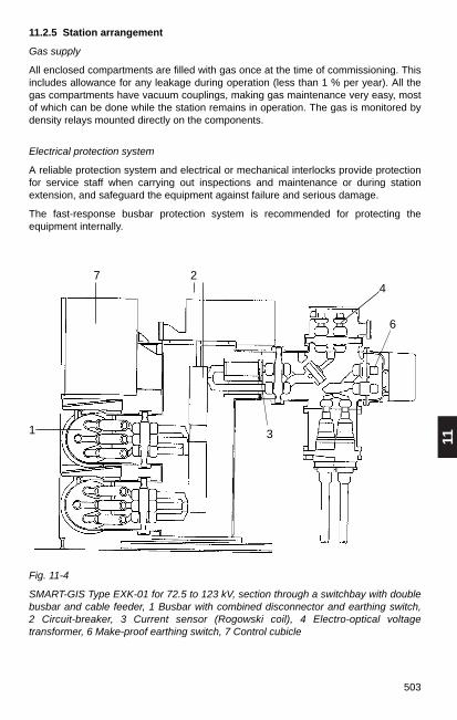
11
503
11.2.5 Station arrangement
Gas supply
All enclosed compartments are filled with gas once at the time of commissioning. Thisincludes allowance for any leakage during operation (less than 1 % per year). All thegas compartments have vacuum couplings, making gas maintenance very easy, mostof which can be done while the station remains in operation. The gas is monitored bydensity relays mounted directly on the components.
Electrical protection system
A reliable protection system and electrical or mechanical interlocks provide protectionfor service staff when carrying out inspections and maintenance or during stationextension, and safeguard the equipment against failure and serious damage.
The fast-response busbar protection system is recommended for protecting theequipment internally.
Fig. 11-4
SMART-GIS Type EXK-01 for 72.5 to 123 kV, section through a switchbay with doublebusbar and cable feeder, 1 Busbar with combined disconnector and earthing switch, 2 Circuit-breaker, 3 Current sensor (Rogowski coil), 4 Electro-optical voltagetransformer, 6 Make-proof earthing switch, 7 Control cubicle
1
2
3
4
6
7

504
Earthing
Being electrically connected throughout, the switchgear enclosure acts as an earth bus.It is connected at various points to the station earthing system. For inspection or duringstation extension, parts of the installation can be earthed with suitably positionedmaintenance earthing switches. Protective earthing for disconnected cables, overheadlines or transformers is provided by short-circuit make-proof earthing switches locatedat the outgoing feeders.
By short-circuiting the insulation between earthing switch and metal enclosure duringoperation, it is possible to use the earthing switch to supply low-voltage power or tomeasure switching times and resistances. Thus there is no need to intervene inside theenclosure.
Erection and commissioning
Only lightweight cranes and scaffolding are required. Cranes of 5000 kg capacity arerecommended for complete bays, lifting gear of 2000 to 4000 kg capacity is sufficientfor assembling prefabricated units.
Cleanliness on site is very important, particularly when erecting outdoors, in order toavoid dirt on the exposed parts of joints.
The completely installed substation undergoes a voltage test before entering operation.This is done with eighty per cent of the rated power-frequency test voltage or impulsewithstand voltage. If a test transformer of suitable size is available, testing is done witha.c. voltage. Resonance test equipment or generators for oscillating switching surgesare commonly used with rated voltages above 245 kV.
11.2.6 Station layouts
The modular construction of SF6 switchgear means that station layouts of all the basiccircuit configurations shown in Section 11.1 are possible.
For layout engineering, attention must be paid to DIN VDE 0101. Sufficientlydimensioned gangways must allow unhindered access to the components for erectionand maintenance. Minimum gangway distances must be observed even when thecubicle doors are open. A somewhat larger floor area, if necessary at the end of theinstallation, facilitates erection and later extensions or inspection.
A separate cable basement simplifies cable installation and distribution. Where outdoorlines terminate only at one side of the building, the required clearances betweenbushings determine the position of the SF6-switchgear bay. These are usually atintervals of three to four bays. If overhead line connections are brought out on bothsides of the building or are taken some distance by means of SF6 tube connections, therespective feeder bays can be next to each other.
Installations of the model ranges EXK-01 for 72.5/123 kV and ELK-0 for 145/170 kV asshown in Fig. 11-5 are extremely compact because of the three-phase encapsulation ofall components. Combining busbar, disconnector and earthing switch into oneassembly reduces the depth of the building.
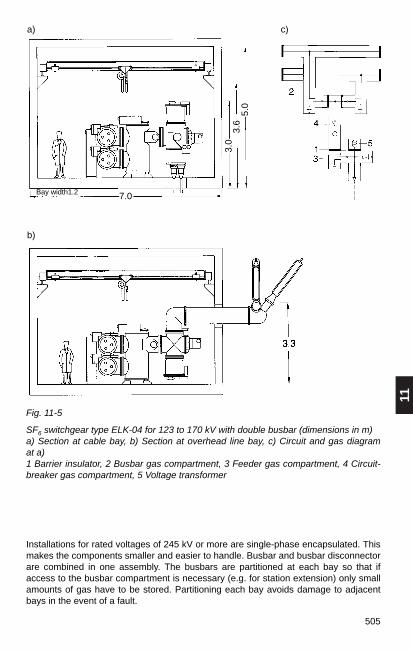
11
505
Fig. 11-5
SF6 switchgear type ELK-04 for 123 to 170 kV with double busbar (dimensions in m)a) Section at cable bay, b) Section at overhead line bay, c) Circuit and gas diagram at a)1 Barrier insulator, 2 Busbar gas compartment, 3 Feeder gas compartment, 4 Circuit-breaker gas compartment, 5 Voltage transformer
a) c)
b)
Installations for rated voltages of 245 kV or more are single-phase encapsulated. Thismakes the components smaller and easier to handle. Busbar and busbar disconnectorare combined in one assembly. The busbars are partitioned at each bay so that ifaccess to the busbar compartment is necessary (e.g. for station extension) only smallamounts of gas have to be stored. Partitioning each bay avoids damage to adjacentbays in the event of a fault.
Bay width1.2 7.0
3.0
3.6
5.0

506
Fig. 11-6
SF6 switchgear installation type ELK-14 for rated voltage 245 to 300 kV (dimensions inm) a) Cable feeder, b) Overhead Line branch
a)
b)
The structural type with standing breaker is preferred in all installation layouts. Thisallows the interrupter chambers to be easily removed from the circuit-breakers with acrane or lifting gear.
Single busbars, formerly used only for small installations, have become more importantowing to the high reliability of the apparatus and its outstanding availability. Plantoperation has become less complicated by dividing the station into sections by meansof bus-ties.

11
507
Bypass buses with their disconnectors add another busbar system to stations withsingle or double busbars. The bypass bus enables any circuit-breaker to be isolatedwithout interrupting the feeders.
A special form of the single busbar is the H connection or double H connection. It isemployed chiefly for load centres in urban and industrial areas. These stations oftenhave switch-disconnectors instead of circuit-breakers.
Combined busbars: In GIS stations with double busbars the second busbar isincreasingly used as a bypass bus with the aid of an additional disconnector, resultingin a so-called combined busbar. This greatly improves the station availability at littleextra cost.
11.2.7 SF6-insulated busbar links
SF6-insulated busbar links are particularly suitable for transmitting high power.They complement the usual cables and overhead lines for voltages above 72.5 kV, seeTable 11-2.
They have the following advantages over cable links: greater transmission capacitywith smaller losses, low charging power, non-ageing oil-free insulation, earthedenclosure with full earth-fault current carrying capacity. Large differences in height areeasily overcome. Bridging considerable distances is possible without shunt reactors.
SF6-insulated tie links are often left exposed, particularly for shorter distances or inwalkable, covered ducts. Owing to the low ohmic losses, extra cooling is generallyunnecessary.
Table 11-2
Rating data and dimensions of the SF6 insulated busbar connections type CGI (typicalvalues)
Service voltage kV 72.5 123 145 245 420 550 800
Transmission outputabove ground MVA 175 450 525 1200 3250 4800 7400underground MVA 125 250 300 650 1600 2200 3300
Rated current, underground A 1000 1200 1200 1500 2100 2300 2400
Losses at rated current, 3ph W/m 115 105 105 120 148 154 180
Weight with SF6 gas, 1ph kg/m 13.2 14.5 14.5 30.9 44.7 50.3 59.3
Gas pressure at 20 °C kPa 420 420 420 420 420 420 420
External diameter mm 165 240 240 310 470 510 620
Centre-to-centre distance of phases mm 305 370 370 460 660 710 810
Right-of-way width mm 1200 1300 1300 1500 2100 2300 2600

508
11.3 Outdoor switchgear installations
11.3.1 Requirements, clearances
The minimum clearances in air and gangway widths for outdoor switching stations areas stated in DIN VDE 0101 or specified by IEC. They are listed in the rated insulationlevels as per DIN EN 60071-1 (VDE 0111 Part 1) (see Table 4-10 in Section 4.6.1).Where installation conditions are different from the standardized atmosphericconditions, e.g. installations at high altitudes, they must be taken into account by theatmospheric correction factor by determining the required withstand voltage in thecourse of the insulation coordination (compare Section 4.1).
Where phase opposition cannot be ruled out between components having the sameoperating voltage, the clearances must be at least 1.2 times the minimum values. Theminimum distance between parts at different voltage levels must be at least the valuefor the higher voltage level.
When wire conductors are used, the phase-to-phase and phase-to-earth clearancesduring swaying caused by wind and short-circuit forces are allowed to decrease belowthe minimum values. The values by which the clearances are permitted to extend belowthe minima in this case are stated in DIN VDE 0101, Para. 4.4.
Equipment for outdoor switching stations is selected according to the maximumoperating voltage on site and the local environmental conditions. The amount of airpollution must be taken into account, as on outdoor insulators, it can lead to flashovers.The hazard these represent can be influenced by the shape of the insulator, byextending the creepage distance, by siliconizing and by cleaning. IEC 60815 definesvarious degrees of contamination and specifies minimum creepage distances inrelation to the equipment’s maximum voltage Um (see Table 11-3).
Table 11-3
Degree of Examples Minimumcontamination creepage distance
mm/kV
I slight Predominantly rural areas without industry and far 16from sea air
II moderate Areas in which little severe pollution is expected 20
III severe Industrial areas with relatively severe pollution, sea 25air, etc.
IV very severe Areas with heavy industry and much dust, fog, sea air 31
Lengthening the creepage distance with the same insulator height is not an effectivemethod of preventing flashovers due to pollution deposits.
11
509
11.3.2 Arrangement and components
Surge arresters
Surge arresters for limiting atmospheric and switching overvoltages are described inSection 10.6. The protection zone of an arrester is limited. For rated voltages of 123 kV,the arrester should therefore not be further than approx. 24 m distant from the protectedobject, and for 245 to 525 kV, not further than approx. 32 m. The minimum distancesfrom neighbouring apparatus must conform to the arrester manufacturer’s specificinstructions.
PLC communication
The power line carrier (PLC) system is a means of communicating over high-voltagelines. A PLC link requires a line trap and capacitor or capacitive voltage transformer inone or two phases of the incoming lines, positioned as shown in Fig. 11-14.
Control cubicles and relay kiosks
In outdoor switchyards, the branch control cubicles are of steel or aluminium sheet orof plastic (GFR polyester-reinforced resin). The cubicles contain the controls for localoperation, auxiliary equipment and a terminal block for connecting the control,measuring and auxiliary cables. The size depends on how much equipment they haveto contain. In large switchyards, the cubicles are replaced by relay kiosks containing allthe equipment for controlling and protecting two or more high-voltage branches.
Busbars and connections
Busbars and the necessary connections to the equipment can be of wire or tube.Busbars are usually of aluminium/steel wire strung between double dead-end strings ofcap-&-pin type or long-rod insulators with means of arc protection. Bundle conductorsare employed for high voltages and high currents, and when single-columndisconnectors are used. The tension of the wires is selected to be as small as possibleto reduce stresses on the gantries. The choice of tension is further governed by thevariation in sag.
In the case of spans carrying the stirrup contacts of single-column disconnectors,account must be taken of the difference in sag at temperatures of –5 °C plus additionalload and +80 °C. The change in sag can be reduced by means of springs located at oneend of the span between the dead-end string and the portal structure.
Wires with cross sections of at least 95 mm2 are used for installations with a ratedvoltage of 123 kV. At higher operating voltages, wires of not less than 300 mm2 or twoparallel wires forming a bundle-conductor are employed in view of the maximumpermissible surface voltage gradients (see Section 4.3.3). Tensioned conductors areusually of aluminium/steel and rarely of aluminium. Aluminium wire is used forconnections to HV equipment where the conductors are not tensioned, but only strungloosely. Wires are selected on the basis of mechanical and thermal considerations, seeSections 4.2.2, 4.2.3, 4.3.1 and 13.1.4.
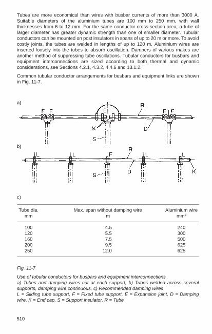
510
Tubes are more economical than wires with busbar currents of more than 3000 A.Suitable diameters of the aluminium tubes are 100 mm to 250 mm, with wallthicknesses from 6 to 12 mm. For the same conductor cross-section area, a tube oflarger diameter has greater dynamic strength than one of smaller diameter. Tubularconductors can be mounted on post insulators in spans of up to 20 m or more. To avoidcostly joints, the tubes are welded in lengths of up to 120 m. Aluminium wires areinserted loosely into the tubes to absorb oscillation. Dampers of various makes areanother method of suppressing tube oscillations. Tubular conductors for busbars andequipment interconnections are sized according to both thermal and dynamicconsiderations, see Sections 4.2.1, 4.3.2, 4.4.6 and 13.1.2.
Common tubular conductor arrangements for busbars and equipment links are shownin Fig. 11-7.
c)
Tube dia. Max. span without damping wire Aluminium wiremm m mm2
100 4.5 240120 5.5 300160 7.5 500200 9.5 625250 12.0 625
Fig. 11-7
Use of tubular conductors for busbars and equipment interconnectionsa) Tubes and damping wires cut at each support, b) Tubes welded across severalsupports, damping wire continuous, c) Recommended damping wiresL = Sliding tube support, F = Fixed tube support, E = Expansion joint, D = Dampingwire, K = End cap, S = Support insulator, R = Tube
a)
b)

11
511
High-voltage terminals (connectors, clamps)
High-voltage HV terminals connect high-voltage apparatus to electrical conductors.
Their purpose is to provide a permanent, corona-free connection of sufficient thermal/mechanical strength for continuous and short-circuit currents at the maximum operatingvoltage.
Unless specified otherwise, HV terminals conform to DIN VDE 48084, 46203 and46206 Parts 2 and 3.
Besides current conducting terminals, the conductors require purely mechanicalsupports attaching them to the insulators, see Fig. 11-7.
The principal kinds of terminal connection are shown in Fig. 11-8.
1 HV apparatus with connection bolt2 HV apparatus with flat pad 3 Stranded wire conductor 4 Tubular conductor 5 Support insulator a Screw type terminal, bolt/wire b Screw type terminal, bolt/tube c Compression terminal with flat pad d Screw type terminal flat pad / wire e Screw type terminal flat pad / tube f Conductor support for wire g Conductor support for tube h Tube connector k Wire connector
Fig. 11-8
High-voltage terminals, alternative connections for outdoor switchgear installations
a
Depending on the installation site, straight, 45° angle or 90° angle HV terminals areused. With stranded wire connections, terminals are used for both a single strandedwire and for bundled wires.

512
HV terminals have to satisfy a number of technical requirements. To select the correctterminal, the following points need to be considered:
– design, e.g. screw type flat terminal
– material of body, screws
– conductor type, e.g. stranded wire Al 400 mm2 to DIN 48201, dia. 26.0 mm
– contact area or surface of pin, e.g. flat terminal to DIN 46206 Part 3
– rated voltage, e.g. 380 kV
– surface voltage gradient
– rated current, e.g. 2000 A
– peak short-circuit current, e.g. Is = 80 kA
– total opening time or short-circuit duration
– ambient temperatures
– ultimate temperatures terminal/conductor
– mechanical stress
– specific environmental factors
When connecting different materials, e.g. terminal bolt of Cu to stranded wire conductorof Al, a cover or plate of Cupal (a Cu/AI bimetal) is usually inserted between terminaland apparatus connector. Two-metal (Al/Cu) terminals are used where the local climateis unfavourable. The two different materials of these terminals are factory-bonded toprevent corrosion.
Special care is called for when selecting and using terminals and conductor supportsfor aluminium tubes 100 mm diameter. The following additional criteria must beconsidered:
– elongation in the case of lengthy tubes
– tube supports, fixed or sliding
– tube oscillation induced by wind
– connection to apparatus, fixed or flexible (expansion joint) see also Fig. 11-7.
Fig. 11-9 shows the terminal arrangement and a terminal listing for 110 kV outdoorbranches.

11
513
b)
Pos. Symbol Mat. Rated Description Total Location Baycurrent Qty. 1 2 3(A)
1 Al 850 T–terminal 9 BB feeder 3 3 3A = Al tube 63 dia., 2 capsB = Al wire 400 mm2
(26.0 dia.) 3 caps
2 Al 850 Straight flat terminal, 54 BB dis- 6 6 6A = Al wire 400 mm2 connector,(26.0 dia.) 3 caps Current 6 6 6FL = flat term. to transformer,DIN 46206 P3 Feeder dis- 6 6 6
connector
3 Al 850 90° flat terminal 18 Circuit- 6 6 6A = Al wire 400 mm2 breaker(26.0 dia.) 3 caps,FL = flat term. toDIN 46206 P3
4 Al 850 Parallel connector 9 Voltage 3 3 3A & B = Al wire transformer400 mm2 (26.0 dia.), drop off3 screws
5 Al 850 T–terminal 9 Voltage 3 3 3with A = Al wire 400 mm2 transformerCupal. (26.0 dia.) 3 caps connection
B = Cu bolt 30 dia., 2 caps with Cupal cover
6 Al 680 T-terminal with hanger 9 Line 3 3 319 dia. connectionA = Al/St 265/35 mm2
(22.4 dia.) 3 capsB = Al wire 400 mm2
(26.0 dia.) 3 caps
7 Is = 31.5 kA/1s 110 kV V-suspension 9 Line 3 3 3to GSHP 130212 Sh. 4 connection
Fig. 11-9
Example of a) terminal arrangement and b) terminal listing for three 110 kV outdoorbranches
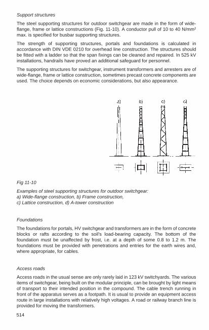
514
Support structures
The steel supporting structures for outdoor switchgear are made in the form of wide-flange, frame or lattice constructions (Fig. 11-10). A conductor pull of 10 to 40 N/mm2
max. is specified for busbar supporting structures.
The strength of supporting structures, portals and foundations is calculated inaccordance with DIN VDE 0210 for overhead line construction. The structures shouldbe fitted with a ladder so that the span fixings can be cleaned and repaired. In 525 kVinstallations, handrails have proved an additional safeguard for personnel.
The supporting structures for switchgear, instrument transformers and arresters are ofwide-flange, frame or lattice construction, sometimes precast concrete components areused. The choice depends on economic considerations, but also appearance.
Fig 11-10
Examples of steel supporting structures for outdoor switchgear: a) Wide-flange construction, b) Frame construction,c) Lattice construction, d) A-tower construction
Foundations
The foundations for portals, HV switchgear and transformers are in the form of concreteblocks or rafts according to the soil’s load-bearing capacity. The bottom of thefoundation must be unaffected by frost, i.e. at a depth of some 0.8 to 1.2 m. Thefoundations must be provided with penetrations and entries for the earth wires and,where appropriate, for cables.
Access roads
Access roads in the usual sense are only rarely laid in 123 kV switchyards. The variousitems of switchgear, being built on the modular principle, can be brought by light meansof transport to their intended position in the compound. The cable trench running infront of the apparatus serves as a footpath. It is usual to provide an equipment accessroute in large installations with relatively high voltages. A road or railway branch line isprovided for moving the transformers.

11
515
Cable trenches, see Fig. 11-11
In outdoor installations, the cables are laid in covered trenches. Large switchyardslacking modern control facilities may require a tunnel with walking access and racks onone or both sides to accommodate the large number of control cables.
The main trenches follow the access road, the branch control cubicles being so placedthat their foundations adjoin the trench. In view of the size of the covering slabs orplates, these cable trenches should not be more than 100 cm wide. Their depthdepends on the number of cables. Cable supports are arranged along the sides. Adescent in the lengthwise direction and drain holes ensure reliable drainage. In eachbranch, ducts are teed off from the control cubicle to the circuit-breaker, the instrumenttransformers and the isolator groups. The top of the main and branch ducts is slightlyabove ground level so that the trench remains dry even in heavy rain. Cableconnections to individual items of equipment can also be laid in preformed troughingblocks or direct in the ground and covered with tiles.
See also civil construction requirements, Section 4.7.2.
Fig. 11-11
a) Plan view of cable trench arrangement for a feeder, diagonal layout, b) Sizes of cabletrenches

516
Protective screens, see Fig. 11-12
Equipment which stands low, e.g. circuit-breakers and instrument transformers on railsat 600 to 800 mm above ground level, must be provided with wire-mesh screens atleast 1800 mm high, or railings at least 1100 mm high. The prescribed protective barrierdistances must be observed (see Section 4.6.1).
Protective screens, railings and the like are not necessary within a switchyard if theminimum height to the top edge of the earthed insulator pedestal is 2250 mm, asspecified in DIN VDE 0101, with account taken of local snow depths.
Perimeter fencing, see Fig. 11-12
The perimeter fence of an outdoor switching station must be at least 1800 mm high.The minimum clearance (between perimeter fence and live parts) must be observed.The perimeter fence is generally not connected to the station earth, owing to the dangerof touch voltages, unless continuous separation is not possible (distance 2 m).
Station perimeter fences of conducting material must be earthed at intervals of no morethan 50 m by means of driven earthrods or earthing strips at least 1 m in length, unlessbonding is provided by means of a surface earth connection approximately 1 m outsidethe fence and about 0.5 m deep.
No special measures are required in the case of perimeter fences of plastic-coated wiremesh with plastic-coated or concrete posts.
Fig. 11-12
Protective barrier clearances and minimumheight H’ at the perimeter fence. Distances asTable 4-11, C Solid wall, E wire-mesh screen

11
517
Fig. 11-13
Principle of fence earthing if distance from earth network to fence 2 ma) Elevation, b) Plan view at gate
11.3.3 Switchyard layouts
General
The arrangement of outdoor switchgear installations is influenced by economicconsiderations, in particular adaptation to the space available and the operationalrequirements of reliability and ease of supervision. To meet these conditions, variouslayouts (see Table 11-4) have evolved for the circuit configurations in Section 11.1.2.Many electric utilities have a preference for certain arrangements which they haveadopted as standard.
The spacing of the branches is determined by the switchyard configuration.
A span length of 50 m is economical for guyed wire (strain) busbars. The number anddesign of portal structures is governed by the overall length of the installation. Thelarger bay width T1 and T2 of the busbar step-down bays (starting bay, end bay) mustbe taken into account when planning the layout.
For stations with busbar current ratings above about 3000 A, tubular busbars offer amore economical solution than tensioned wires. In 123 kV stations, the tubular busbarsare supported at each alternate bay, but at each bay with higher voltages.
The overhead lines leading from the transformer stations are generally also used forpower-line carrier telephony. The necessary equipment (line trap, capacitor) isincorporated in the outgoing overhead lines as shown in Fig. 11-14.
Points in favour of rotary and vertical-break disconnectors are their mechanicalsimplicity and the fact that they are easier to position as feeder disconnectors. The
to

518
single-column disconnector makes for a simple station layout owing to its isolatingdistance between the two line levels; it saves some 20% of the ground area needed fortwo-column disconnectors.
Fig. 11-14
Arrangement of overhead line bays for power-line carrier telephony:
a) Line trap suspended, capacitor standing, b) Line trap mounted on capacitive voltage transformer,1 Circuit-breaker, 2 Feeder disconnector, 3 Current transformer, 4 Inductive voltagetransformer, 5 Capacitive voltage transformer, 6 Capacitor, 7 Line trap
Table 11-4
Outdoor switchyard configurations, preferred application
Layout 145 kV 245 kV 420 kV 525 kV
Low rise (classical)layout × ×
In-line layout ×
Transverse layout × ×
High-rise layout ×
Diagonal layout × ×
1¹₂-breaker layout × × ×
Each branch (bay) consists of the circuit-breaker with its disconnectors, instrumenttransformers and control cubicle. The apparatus is best placed at a height such that nofencing is needed. Here, it must be noted that according to DIN VDE 0101 (Fig. 4-37,Section 4.6.1), the height to the top edge of the earthed insulator base must be at least2250 mm. The high-voltage apparatus is generally mounted directly on equipmentsupport structures.
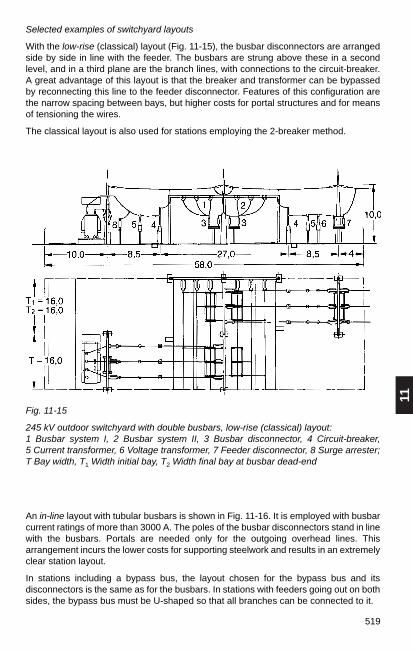
11
519
Selected examples of switchyard layouts
With the low-rise (classical) layout (Fig. 11-15), the busbar disconnectors are arrangedside by side in line with the feeder. The busbars are strung above these in a secondlevel, and in a third plane are the branch lines, with connections to the circuit-breaker.A great advantage of this layout is that the breaker and transformer can be bypassedby reconnecting this line to the feeder disconnector. Features of this configuration arethe narrow spacing between bays, but higher costs for portal structures and for meansof tensioning the wires.
The classical layout is also used for stations employing the 2-breaker method.
Fig. 11-15
245 kV outdoor switchyard with double busbars, low-rise (classical) layout: 1 Busbar system I, 2 Busbar system II, 3 Busbar disconnector, 4 Circuit-breaker, 5 Current transformer, 6 Voltage transformer, 7 Feeder disconnector, 8 Surge arrester;T Bay width, T1 Width initial bay, T2 Width final bay at busbar dead-end
An in-line layout with tubular busbars is shown in Fig. 11-16. It is employed with busbarcurrent ratings of more than 3000 A. The poles of the busbar disconnectors stand in linewith the busbars. Portals are needed only for the outgoing overhead lines. Thisarrangement incurs the lower costs for supporting steelwork and results in an extremelyclear station layout.
In stations including a bypass bus, the layout chosen for the bypass bus and itsdisconnectors is the same as for the busbars. In stations with feeders going out on bothsides, the bypass bus must be U-shaped so that all branches can be connected to it.
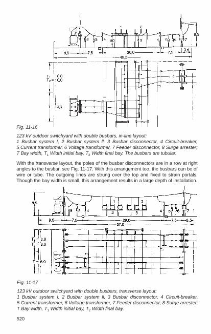
520
Fig. 11-17
123 kV outdoor switchyard with double busbars, transverse layout: 1 Busbar system I, 2 Busbar system ll, 3 Busbar disconnector, 4 Circuit-breaker,5 Current transformer, 6 Voltage transformer, 7 Feeder disconnector, 8 Surge arrester;T Bay width, T1 Width initial bay, T2 Width final bay.
With the transverse layout, the poles of the busbar disconnectors are in a row at rightangles to the busbar, see Fig. 11-17. With this arrangement too, the busbars can be ofwire or tube. The outgoing lines are strung over the top and fixed to strain portals.Though the bay width is small, this arrangement results in a large depth of installation.
Fig. 11-16
123 kV outdoor switchyard with double busbars, in-line layout: 1 Busbar system I, 2 Busbar system ll, 3 Busbar disconnector, 4 Circuit-breaker, 5 Current transformer, 6 Voltage transformer, 7 Feeder disconnector, 8 Surge arrester;T Bay width, T1 Width initial bay, T2 Width final bay. The busbars are tubular.

11
521
Special layouts
Arrangements with draw-out breakers save a great deal of space, as the draw-outcircuit-breaker does away with the need for disconnectors. The outgoing line simplyincludes an earthing switch. This configuration is used for stations with single busbars.The costs are low. The circuit-breaker is fitted with suitable plug-in contacts and ahydraulically operated truck.
Load-centre substations with one or two power transformers are usually in the form ofsimplified transformer stations. In Fig. 11-18, two incoming overhead lines connect totwo transformers (H-connection). This gives rise to two busbar sections joined via twosectionalizers (two disconnectors in series). In this way, each part of the installation canbe isolated for maintenance purposes. The bus sections can be operated separately orcrosswise, ensuring great reliability and security of supply.
Fig. 11-18
123 kV load-centre station (H-connection): 1 Busbars, 2 Busbar disconnector, 3 Circuit-breaker, 4 Current transformer, 5 Voltage transformer, 6 Feeder disconnector, 7 Surgearrester.
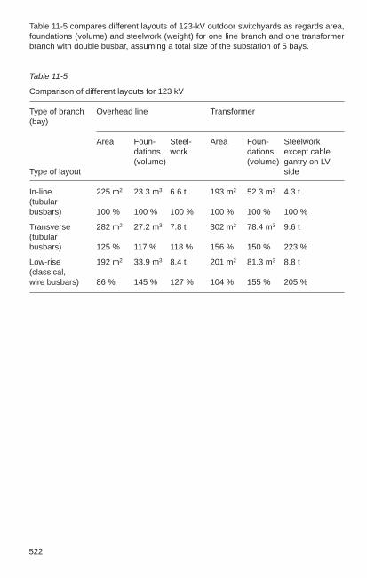
522
Table 11-5 compares different layouts of 123-kV outdoor switchyards as regards area,foundations (volume) and steelwork (weight) for one line branch and one transformerbranch with double busbar, assuming a total size of the substation of 5 bays.
Table 11-5
Comparison of different layouts for 123 kV
Type of branch Overhead line Transformer(bay)
Area Foun- Steel- Area Foun- Steelworkdations work dations except cable(volume) (volume) gantry on LV
Type of layout side
In-line 225 m2 23.3 m3 6.6 t 193 m2 52.3 m3 4.3 t(tubularbusbars) 100 % 100 % 100 % 100 % 100 % 100 %
Transverse 282 m2 27.2 m3 7.8 t 302 m2 78.4 m3 9.6 t(tubular busbars) 125 % 117 % 118 % 156 % 150 % 223 %
Low-rise 192 m2 33.9 m3 8.4 t 201 m2 81.3 m3 8.8 t(classical,wire busbars) 86 % 145 % 127 % 104 % 155 % 205 %

11
523
Table 11-6 compares different layouts of 245-kV outdoor switchyards as regards area,foundations (volume) and steelwork (weight) for one line branch and one transformerbranch with double busbar and bypass bus or 1¹₂-breaker layout.
Table 11-6
Comparison of different layouts for 245 kV
Type of branch Overhead line Transformer(bay)
Area Foun- Steel- Area Foun- Steelworkdations work dations except cable(volume) (volume) gantry on LV
Type of layout side
In-line 323 m2 28.0 m3 7.9 t 344 m2 63.2 m3 7.0 t(tubularbusbars) 100 % 100 % 100 % 100 % 100 % 100 %
Transverse 413 m2 31.9 m3 9.1 t 433 m2 69.2 m3 9.4 t(tubularbusbars) 128 % 114 % 115 % 126 % 110 % 134 %
Low-rise 324 m2 38.6 m3 10.4 t 369 m2 83.1 m3 12.5 t(classical,wire busbars) 100 % 138 % 132 % 107 % 131 % 179 %
1¹₂-breaker 267 m2 27.4 m3 8.1 t 301 m2 47.7 m3 8.5 t(tubularbusbars) 83 % 98 % 103 % 88 % 76 % 121 %

524
Fig. 11-19
420 kV outdoor switchyard with double busbars of tubular type, diagonal layout,busbars above: 1 Busbar system I, 2 Busbar system II, 3 Busbar disconnector, 4Circuit-breaker, 5 Current transformer, 6 Feeder disconnector, 7 Line trap, 8 Capacitivevoltage transformer. T Bay width, T1 Width initial bay, T2 Width final bay
“Busbars below”
With this arrangement, the busbars are mounted on the disconnectors with theoutgoing lines strung at right angles to them. At their points of intersection,single-column disconnectors maintain the connection with their vertical isolatingdistance. This economical layout requires lightweight busbar strain portals only at the
Diagonal layout
With this arrangement, the (single-column) busbar disconnectors are arrangeddiagonally with reference to the busbars. It is commonly used for 245 kV and 420 kVstations.
A distinction is made between two versions, depending on the position (level) of thebusbars.
“Busbars above”
The advantage of this layout (Fig. 11-19) is that when a feeder is disconnected, thebusbar disconnectors are also disconnected and are thus accessible.
For installations with current ratings of more than 3000 A and high short-circuitstresses, the busbars and jumper connections are made of tubes. Fig. 11-19 shows a420 kV station in a diagonal layout and using tubes. The tubes are in lengths of one bayand mounted on the post insulators with a fixed point in the middle and sliding supportsat either end. The busbars can be welded together over several bays up to about 120m.

11
525
ends of the installation, and the bays are narrow. It can be of single or double-row form.The single-row arrangement (Fig. 11-20) is more space-saving. Compared with a two-row layout it requires about 20 % less area. The circuit-breakers for all outgoing linesare on the same side of the busbars so that only one path is needed for transport andoperation. The lines to the transformers lie in a third plane.
Fig. 11-20
245 kV outdoor switchyard with double busbars, diagonal layout, busbars below, single-row arrangement: 1 Busbar system I, 2 Busbar system II, 3 Busbar disconnector, 4 Circuit-breaker, 5 Current transformer, 6 Feeder disconnector, 7 Line trap, 8 Capacitive voltage transformer. T Bay width, T1 Width initial bay, T2 Width final baywith busbar dead-end.
The 420 kV switchyards of the German transmission grid are of the diagonal type. Tomeet the stringent demands of station operation and reliability, double or triple busbarswith sectionalizing and an additional bypass bus are customary. Tube-type busbars arepreferred. These can handle high current ratings and high short-circuit stresses.
The space-saving single-row layout with the circuit-breakers of all outgoing lines in onerow is very effective here, too. Using two-column isolators on the feeders simplifies thelayout. Single-column isolators are used for the busbars and the bypass bus (see Fig.11-21).

526
Fig. 11-21
420 kV outdoor switchyard with tubular conductors, triple busbars and bypass bus,diagonal layout, single-row arrangement: 1 Busbar system I, 2 Busbar system II, 3 Busbar system III, 4 Bypass bus, 5 Busbardisconnector, 6 Circuit-breaker, 7 Feeder disconnector, 8 Bypass disconnector, 9 Current transformer, 10 Voltage transformer; a and b Ties for busbars 1, 2 and 3 andbypass bus 4, c Outgoing line.
1 ¹₂-breaker layout
The 1¹₂-breaker configuration is used mainly in countries outside Europe. It isemployed for all voltages above 110 kV, but predominantly in the very high voltagerange.
The double busbars of these stations are arranged above, both outside or inside, andcan be of tube or wire.
The more economical solution of stranded conductors is often used for the links to theapparatus, because with the relatively short distances between supports, even thehighest short-circuit currents can exert only limited stresses on the equipmentterminals.
The branches are always arranged in two rows. The disconnectors used are of thepantograph and two-column vertical-break types. Vertical-break disconnectors areemployed in the outgoing line. Fig. 11-22 shows a section through one bay of a 525 kVstation; the busbars are of wire. This arrangement allows the station to be operated onthe ring bus principle while construction is still in progress, and before all the switchgearapparatus has been installed.

11
527
Fig. 11-22
525 kV outdoor switchyard, 1¹₂-breaker layout: 1 Busbar system I, 2 Busbar system II, 3 Busbar disconnector, 4 Circuit-breaker, 5 Currenttransformer, 6 Voltage transformer, 7 Feeder disconnector, 8 Branch disconnector, 9 Surge arrester, 10 Line trap, 11 Transformer.

528
11.4 Innovative HV switchgear technology
11.4.1 Concepts for the future
The application of processors and modern information processing technology insubstation and network control systems and also in secondary systems of switchgearinstallations, fast data bus systems that transmit over fibre-optic cables instead ofcopper wires and newly developed sensors for current and voltage can enable anevolutionary spring to smaller and more compact installations with a simultaneoussignificant increase in availability and ease of maintenance in the area of high- and veryhigh-voltage equipment and switchgear installations.
11.4.1.1 Process electronics (sensor technology, PISA)
Decentralized distributed computer-supported modules (PISA = Process Interface forSensors and Actuators) can now be used for direct control of the primary componentsof switchgear installations. At the same time, these modules enable all parameters,such as switch position, gas density, storage properties of operating mechanisms, to berecorded where they signify the current status of the equipment and therefore providethe necessary prerequisites for monitoring modern switchgear installations.
Examples of equipment used for this purpose are inductive (therefore insensitive tocontamination), robust proximity sensors for detecting switch position of circuit-breakers and disconnector mechanisms, gas density sensors for SF6 gas-insulatedswitchgear installations and circuit-breakers. Powerful microcomputers are used fordecentralized preparation and preprocessing of the sensor signals (PISAS). Complexauxiliary switch packets in operating mechanisms are not needed because the softwarecan double the signals without problems. The main advantages of this technology aretherefore the ability to reduce the quantity of moving components, the smallerdimensions and the standardization of mass-produced components as is already donein other industries.
11.4.1.2 Monitoring in switchgear installations
Monitoring includes acquisition, recording and visualizing measured quantities to allowearly detection of faults in important equipment such as circuit-breakers, powertransformers or instrument transformers. According to international surveys conductedby CIGRÉ, the mechanisms and the electrical control circuits in circuit-breakers are theprimary sources of serious faults, i.e. failures causing operational disruptions, and ofless serious faults. The most common sources of failure are the mechanically actuatedparts such as relays and signalling contacts in the electrical control circuits and theprimary components in operating mechanisms.
The influence of the electronics on the total failure response of an installation is takeninto consideration by implementing hardware and software processes for self-monitoring to achieve an increase in internal system reliability.
Condition monitoring requires careful evaluation of the large quantities of measureddata, because only the combination of status acquisition with an intelligent assessmentresults in a knowledgeable diagnosis and initiation of the necessary maintenancesteps. Special algorithms for reducing the data and calculating trends are basicrequirements for a monitoring system. The P-F curve shown in Fig. 11-23 representsthe qualitative connection between the state of a system and the time. As a result of theoperational load on the system under observation, the fault mechanism starts at aspecific time t1, i.e. the state deteriorates until time t2 at which the parameter(s)indicating the fault has/have gone down to a quantifiable value. This point P is
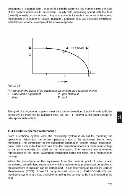
11
529
designated a “potential fault”. In general, it can be assumed that from this time the stateof the system continues to deteriorate, usually with increasing speed until the fault(point F) actually occurs at time t3. A typical example for such a response is the ageingmechanism of oil/paper or plastic insulation. Leakage in a gas-insulated switchgearinstallation is another example of the above response.
t
ZP
F
P-F-Intervall
t1 t2 t3
Fig. 11-23
P-F curve for the status of an equipment parameters as a function of timeZ status of the equipment P potential fault t time F fault
The goal of a monitoring system must be to allow detection of point P with sufficientsensitivity, so there will be sufficient time, i.e. the P-F interval is still great enough totake appropriate action.
11.4.1.3 Status-oriented maintenance
From a technical system view, the monitoring system is an aid for recording theoperational history and the current operating status of the equipment that is beingmonitored. The connection to the substation automation system allows installation-based data such as fault record data from the protection devices or the busbar voltageto be simultaneously included in the evaluation. The resulting status-orientedreproduction of the entire switchgear installation forms the basis for a maintenanceconcept.
When the importance of the equipment from the network point of view is alsoconsidered, an optimized sequence in which a maintenance process can be applied tothe equipment in question can be determined. This is referred to as Reliability CentredMaintenance (RCM). Powerful computerized tools (e.g. CALPOS-MAIN®) andmonitoring systems are now available, enabling this concept to be implemented in thefield.
P-F interval

530
The principle of status-oriented and reliability-based maintenance planning is shown inFig. 11-24
A A
Sensoren undAktoren
Sensoren undAktoren
Sensoren,Aktoren
Sensoren,Aktoren
Stat A
B 8 B 9
C 1
T1 T2
B 1 B 2
B 3 B 4 B 5 B 6 C 7
C 2
B 7
Stat A
B 8 B 9
C 1
T1 T2
B 1 B 2
B 3 B 4 B 5 B 6 C 7
C 2
B 7
Instandhaltungs-strategie
serieller Datenbus
parallele VerdrahtungInformationsfluß (allg.)
Wichtigkeit derBetriebsmittelim Netz
InstandhaltungsplanungStationsleit- undKommunikationsrechnermit Monitoringfunktion
Feld-leitebene
Zustand der Betriebsmittel
Stations-leitebene
Hochspannung Mittelspannung
Fig. 11-24
General technical concept of status-oriented and reliability-based maintenanceplanning
a)
Fig. 11-25 shows how an appropriate software tool can support this task. Fig. a) showsa valuation form for a single item of equipment, a circuit-breaker in this case, and b)shows the result of a simulation. The graph shows the weighted action requirementtransferred to the “importance” of the equipment.
maintenance planningsubstation control andcommunication computerwith monitoring function
equipment statussubstationcontrol level
bay controllevel
maintenancestrategy
high voltage medium voltage
sensors andactuators
sensors andactuators
sensors,actuators
sensors,actuators
serial data busparallel wiringinformation flow (gen.)
importance of equipmentin the network

11
531
Fig. 11-25
Input screen and results display of the software tool CALPOS-MAIN® for status-oriented maintenance planning of switchgear installationsa) Valuation form b) Results display
b)
11.4.2 Innovative solutions
11.4.2.1 Compact outdoor switchgear installations
A significant step toward reducing the space requirements of switchgear installationshas been made by combining primary devices into more and more compactmultifunctional switchgear units. This concept is not new and has already beenimplemented many times in applications such as outdoor switchgear installations withdraw-out circuit-breakers. The implementation of non-conventional current and voltagetransformers now makes it possible to combine a large number of functions on onedevice bench. As a result, a range of combination switchgear has been developed inthe last few years.
Another possibility for reducing the area required for outdoor installations significantlyis to use hybrid installation designs. In this case, gas-insulated switchgear is used inwhich many primary components (circuit-breakers, transformers, disconnectors etc.)are installed in a common housing. Only the busbars and, depending on the basicdesign, the associated busbar disconnectors are installed outdoors
All new switchgear components are distinguished by consistent integration of non-conventional sensors (in this case primarily current and voltage sensors), processor-controlled mechanisms (see 11.4.1.1) and connection to the bay control with fibreoptics. This yields the following:
– increased availability– less space required– shorter project runtimes and – extended maintenance intervals with a significant increase in ease of maintenance.

532
An example of the layout of a simple H-configuration with these modules is shown incomparison to a conventional H-configuration in Fig. 11-27. Dispensing with busbarsand outgoing-feeder disconnectors allows smaller dimensions in comparison toconventional outdoor installations.
Fig. 11-27
View of two installation layouts in H-configuration for Un ≤ 145 kv in conventional andcompact design, T Transformers, S Secondary technology
Konvent ionelleH-SchaltungGesamtes Gelände: 2600 m2
Schaltanlage: 930 m2
Erdungsnetz : 3700 m2
Kompakte H-SchaltungGesamtes Gelände: 1200 m2
Schaltanlage: 300 m2
Erdungsnetz : 1000 m2
S
ST
T
5 Funktionen in 1 Modul 1
2
3 3
Leistungsschalter (1)
Stromwandler (2)
2 Trenner (3) undErdunggsschalter, wenngewünscht
1 Überspannungsableiter (4)kann den Stützisolator ersetzen
4
Fig. 11-26 shows a design for compact outdoor switchgear installations for Un ≤ 145 kv with transverse LTB circuit-breakers and integrated SF6 currenttransformers. The illustrated compact and prefabricated switchgear with prefabricatedbusbar connections makes it easy to set up simple secondary substations and H-configurations economically and quickly. The circuit is disconnected on both sides ofthe circuit-breaker by the module moving to the side.
Fig. 11-26
Slide-in, compact switching module with LTB circuit-breaker and integrated SF6 currenttransformer for Un ≤ 145 kv
5 Functions in 1 module
1 Circuit-breaker
2 Current transformer
3/4 Disconnector and earthingswitch, if required
5 Surge arrester can replacethe post insulator
3/4
2
5
1
3/4
Conventional Design
total area: 2600 m2
switchgear installation: 930 m2
earthing system: 3700 m2
Compact Design
total area: 1200 m2
switchgear installation: 300 m2
earthing system: 1000 m2

11
533
Fig. 11-29 shows a compact switching module for applications of up to 550 kV. It is acombination of a circuit-breaker with one or two non-conventional current transformersinstalled on the interruptor chambers and two pantograph disconnectors. This compactdesign is only possible using very small non-conventional current transformers. Thecurrent transformer signals are conducted through the tension insulators via fibre-opticcables to the control cubicle. Such compact modules make it possible to reduce thesurface area required for an outdoor installation by up to 55 %. This concept isparticularly suitable for installations in 11/2 circuit-breaker design.
1
1 Ausfahrbarer Leistungsschalter
2 Leistungsschalter Fahrschiene
3 Trenner Einfahrkontakte (bilden bei ausgefahrenem LS die Trennstrecke)
4 Stomwandler
2
3
34
1 Draw-out circuit-breaker
2 Circuit-breaker rails
3 Disconnector isolating contact,fixed side (forms the isolating distance for circuit-breaker when withdrawn)
4 Current transformer
Another variation of a compact switching module for use up to 170 kV is shown in Fig.11-28. The disconnector functions are realized with a draw-out circuit-breaker. Thismeans that the conventional disconnectors are replaced by maintenance-free fixedcontacts and moving contacts on the circuit-breaker. An option is to install conventionalor optical current and voltage transformers and earthing switches. The circuit-breakercan be simply withdrawn for maintenance, or if necessary, quickly replaced by a sparebreaker. The main advantages here are also significant space savings, smaller bases,steel frames and reduced cabling requirements. This switching module is particularlysuited for single busbars and H-configurations.
Fig. 11-28
Compact switching module for Un ≤ 170 kv with draw-out circuit-breaker
Fig. 11-29
Compact switching module for Un ≤ 550 kv with circuit-breaker, a built-in non-conventional current transformer and two pantograph disconnectors
bis 550 kV
en Seitenöglich)
ndler (3)
Lichtwellenleiter (4)
12
2
3
4
1 Circuit-breakers of up to 550 kV
2 Disconnectors on both sides(earthing switch possible)
3 Optical current transformer
4 Tension insulator for fibre optics
1

534
Fig. 11-30 shows a comparison of a conventional 500 kV outdoor switchgearinstallation in 11/2 circuit-breaker design with an installation in compact design using themodules described above. This makes the saving in surface area with the samefunctionality particularly clear.
11.4.2.2 Hybrid switchgear installations
Two insulation media, i.e. air and SF6, can be combined in high-voltage installationswith the modular principle of SF6-isolated installations. This type of installation isreferred to as a “hybrid installation”.
Fig. 11-31 shows a hybrid switching device for voltage levels of up to 550 kV. The name“Plug And Switch System” – PASS – indicates the philosophy of this concept. Thehighly integrated components allow that in new installations and in retrofit projectscompact PASS units can be erected and comissioned quickly. These units areconnected to the secondary equipment of the substation by prefabricated cable links,which include both the auxiliary voltage supply cables and the fibre-optic cables toconnect to the station control system.
Fig. 11-30
Switchgear installation design of a 500 kV 11/2 circuit-breaker installation with compactswitching modules a), compared to conventional design b), comparison of areas c)
a)
b)
c)
b
a
117 m x 28 m
190 m x 32 m

11
535
L
CB
DS DS
ES
BB1
BB2
VT
Fig. 11-32 shows a double-busbar installation with PASS modules. The saving of spaceamounts to as much as 60% in new installations. For retrofit projects, the spacerequired by the switchgear installations is generally dictated by the existing busbarsand the gantries. In this case, the advantages of the PASS solutions are primarily in thesavings in foundations, drastically reduced cabling requirements and fast installationand commissioning.
Circuit-breaker
Operating mechanism
Bushing
Fig. 11-31
Plug and Switch System, PASS, in single-phase design for Un of up to 550 kV
Disconnectorswitches
LEGENDELS LeistungsschalterCT StromwandlerDS Trenner
ES Erdungsschalter VT EOVT / Elektrooptischer
Spannungswandler
Legende:
Leistungsschalter CBTrenner DSErdungsschalter ESStromwandler CTSpannungswandler VTÜberspannungsableiter SAWellensperre LTTransformator TLeitung L
13 m
30 m
Fig. 11-32
Switchgear installation design with PASS for double-busbar installations for Un of up to 550 kV
PASS PASS T
a)
Legende:
Leistungsschalter CBTrenner DSErdungsschalter ESStromwandler CTSpannungswandler VTÜberspannungsableiter SAWellensperre LTTransformator TLeitung L
The 11/2 circuit-breaker method can also be successfully implemented in hybrid design,see Fig. 11-33.
Current/voltagesensor
LegendLS circuit-breakerCT current transformerDS disconnectorES earthing switchVT EOVT/electro-optical
voltage transformer
Legende:
circuit-breaker CBdisconnector DSearthing switch EScurrent transformer CTvoltage transformer VTsurge arrester SAline trap LTtransformer Tline L
Maintenanceearthing switch
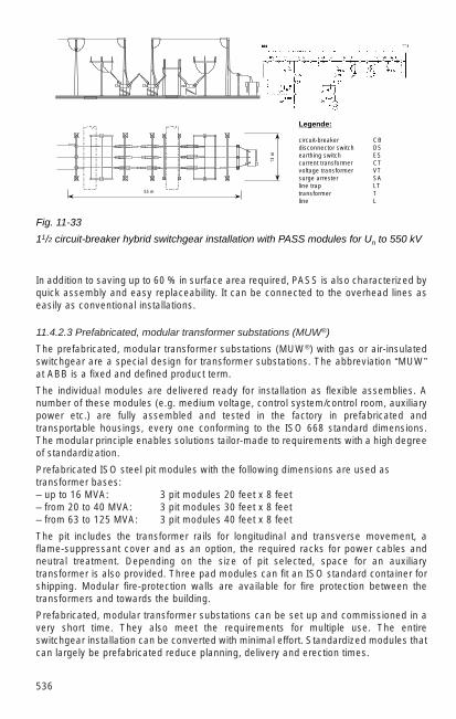
536
In addition to saving up to 60 % in surface area required, PASS is also characterized byquick assembly and easy replaceability. It can be connected to the overhead lines aseasily as conventional installations.
11.4.2.3 Prefabricated, modular transformer substations (MUW®)
The prefabricated, modular transformer substations (MUW®) with gas or air-insulatedswitchgear are a special design for transformer substations. The abbreviation “MUW”at ABB is a fixed and defined product term.
The individual modules are delivered ready for installation as flexible assemblies. Anumber of these modules (e.g. medium voltage, control system/control room, auxiliarypower etc.) are fully assembled and tested in the factory in prefabricated andtransportable housings, every one conforming to the ISO 668 standard dimensions.The modular principle enables solutions tailor-made to requirements with a high degreeof standardization.
Prefabricated ISO steel pit modules with the following dimensions are used astransformer bases:– up to 16 MVA: 3 pit modules 20 feet x 8 feet– from 20 to 40 MVA: 3 pit modules 30 feet x 8 feet– from 63 to 125 MVA: 3 pit modules 40 feet x 8 feet
The pit includes the transformer rails for longitudinal and transverse movement, aflame-suppressant cover and as an option, the required racks for power cables andneutral treatment. Depending on the size of pit selected, space for an auxiliarytransformer is also provided. Three pad modules can fit an ISO standard container forshipping. Modular fire-protection walls are available for fire protection between thetransformers and towards the building.
Prefabricated, modular transformer substations can be set up and commissioned in avery short time. They also meet the requirements for multiple use. The entireswitchgear installation can be converted with minimal effort. Standardized modules thatcan largely be prefabricated reduce planning, delivery and erection times.
55 m
13 m
Legende:
Leistungsschalter CBTrenner DSErdungsschalter ESStromwandler CTSpannungswandler VTÜberspannungsableiter SAWellensperre LTTransformator TLeitung L
Fig. 11-33
11/2 circuit-breaker hybrid switchgear installation with PASS modules for Un to 550 kV
Legende:
circuit-breaker CBdisconnector switch DSearthing switch EScurrent transformer CTvoltage transformer VTsurge arrester SAline trap LTtransformer Tline L

11
537
Some advantages of MUW® are:
– faster construction of infrastructure– shortest possible interruption of power supply in the event of faults and on installation
of new equipment and retrofit and service of existing installations– reusable interim solution (temporary solution)– stationary, space saving permanent solution– auxiliary supply in power stations and power station generator busducts
The modular housing design for the MUW consists of hot-galvanized sandwich wallpanels for extremely high durability. The steel base frame comprises hot-galvanizedrolled steel sections with additional equipment racks. Heating and air-conditioning unitsin the individual modules allow installation independent of the local climate conditions.
Figs. 11-34 and 11-35 show the ground plan and the sectional view of a 123/24 kVtransformer substation with two 63 MVA transformers and an H-configuration with 5 circuit-breakers on the high-voltage side.
20900
6769
2 1 3 4 5
AA
1460
0
Fig. 11-34
Ground plan of a prefabricated, modular transformer substation, 1 High-voltagesubstation: H-configuration ELK-0 with 5 circuit-breakers, 2 Medium-voltageswitchgear: 24 bays, 3 Neutral treatment (under module 1), 4 Auxiliary supply, 5 Controlsystem/control room, 6 Modular transformer oil pit with 63 MVA transformer, 7 Modular fire protection wall, 9 Personnel module with small sewage system and oilseparator
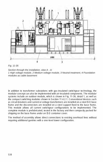
538
Fig. 11-35
Section through the installation, view A - A: 1 High voltage module, 2 Medium voltage module, 3 Neutral treatment, 4 Foundationmodules as cable basement
In addition to transformer substations with gas-insulated switchgear technology, themodular concept can also be implemented with air-insulated components. The modularsystems include an outdoor module, which is shown in Fig. 11-36, detail 1, as well asthe compact switching modules shown in Section 11.4.2.1. Conventional devices suchas circuit-breakers and current or voltage transformers are installed on a steel ISO baseframe and the disconnectors are installed on a steel support fixed to the base frame.This module allows all current switchgear configurations to be implemented. Thecomplete module is prefabricated, tested in the factory and then compactly packed forshipping on the base frame under an ISO container cover.
The method of assembly allows direct connections to existing overhead lines withoutrequiring additional gantries with a one-level tower configuration.
2
1
34
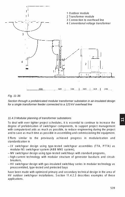
11
539
11.4.3 Modular planning of transformer substations
To deal with ever tighter project schedules, it is essential to continue to increase thedegree of prefabrication of switchgear components, to support project managementwith computerized aids as much as possible, to reduce engineering during the projectand to save as much time as possible in assembling and commissioning the equipment.
Efforts similar to the previously achieved progress in modularization andstandardization in
– LV switchgear design using type-tested switchgear assemblies (TTA, PTTA) asmodular NS switchgear system (ABB MNS system),
– MV switchgear design using type-tested switchbays with standard programs,– high-current technology with modular structure of generator busducts and circuit-
breakers,– HV switchgear design with gas-insulated switchbay series in modular technology as
preassembled, type-tested and pretested bays
have been made with optimized primary and secondary technical design in the area ofHV outdoor switchgear installations. Section 11.4.2.3 describes examples of theseapplications.
Fig. 11-36
Section through a prefabricated modular transformer substation in air-insulated designfor a single transformer feeder connected to a 123 kV overhead line
1 Outdoor module2 Transformer module3 Connection to overhead line4 Conventional voltage transformer
1
2
3
4

540
11.4.3.1 Definition of modules
More highly integrated modules and function groups as modules are required to reducethe project periods for switchgear installations.
A module in this sense is a unit or a function group,– that can execute a self-contained function,– that has a minimum of interfaces, which are as standardized as possible,– whose complex function can be described with few parameters,– that can be prefabricated and pretested to a great extent and – that can be altered within narrow limits by the smallest possible degree of adaptation
engineering for customer demands and requirements while adhering to standards asmuch as possible.
It is essential that any changes to modules do not detract from the rationalization andquality achieved by type testing, degree of prefabrication and pre-testing.
11.4.3.2 From the customer requirement to the modular system solution
The progressive deregulation in energy markets and the accompanying downwardpressure on costs is resulting in new requirements on the project planning oftransformer substations. In addition to the engineering of classical customizedinstallations, the modular switchgear installation concept offers the chance ofdeveloping largely standardized and therefore more economical solutions. This is doneby implementing a systematic pattern of thinking to yield products with high functionalityand combined installation modules. This means that the interfaces are unified and alsoreduced in number by grouping products into modules.For project planning and engineering, this means that system solutions are generatedfrom a modular system of components in which the individual modules are preciselydescribed as derived from the technical and economical requirements of a newtransformer substation in the network. The available CAD systems are ideally suited forquick and easy combination of complete station components from a catalogue ofindividual components. The current integrated enterprise resource planning (ERP)software also offer suitable databases and structures that enable quick access todescriptions, parts lists and prices.The substation planner will have the greatest optimization effect when the customerprovides requirements that describe functions only instead of detailed requirements inthe form of comprehensive specifications. This gives the engineer the greatest possiblefreedom to bring the system requirements into conformity with the available modularsolutions. In the modular concept, detailed installation requirements that go far beyondthe description of functions result in expensive adaptation work, making the overallinstallation more expensive. Adaptation work in the modular concept is possible, but italways results in extra work in preparing the tender, project planning, engineering,processing and documentation of the installation.

11
541
ModularerBaukasten
Technische undökonomische
Anforderungen
Konzeptionierungund
Projektierung
Optimiertemodulare
Systemlösung
KonventionelleKomponeten
Fig. 11-37
From the functional requirements of the network to the modular system solution
11.5 Installations for high-voltage direct-current (HVDC) transmission
11.5.1 General
Transmitting energy in the form of high-voltage direct current is a technical andeconomic alternative to alternating-current transmission. It is used for transferringpower in bulk over large distances by overhead line or cable, for coupling non-synchronous networks and for supplying densely populated areas if there is a shortageof transmission routes.
The basic principle of a HVDC link is shown in Fig. 11-38. The alternating voltage of asupply system, which may also be a single power station, is first transformed to a valuesuitable for transmission. It is then rectified in a converter arrangement with controlledvalves. A second converter is required at the other end of the link. This is operated asan inverter and converts the direct current back into alternating current, which is thentransformed to the voltage of the network being supplied.
The flow of power along the line is determined by the difference between the d.c.voltages at the ends of the line and by the ohmic resistance of the line, according to theformula
Ud1 + Ud2 Ud1 – Ud2 U2d1 – U2
d2Pd = Ud · Id = ———— · ———— = ————— . Here, Pd is the power relating 2 R 2 R
to the middle of the line, Ud1 and Ud2 are the d.c. voltages at the beginning and end ofthe line, respectively, and R is the ohmic line resistance.
Fig. 11-38
Block diagram of a HVDC link
Modular box ofbuilding blocks
Technical andeconomic
requirements
Concept and
planning
Optimizedmodular system
solution
Conventionalcomponents
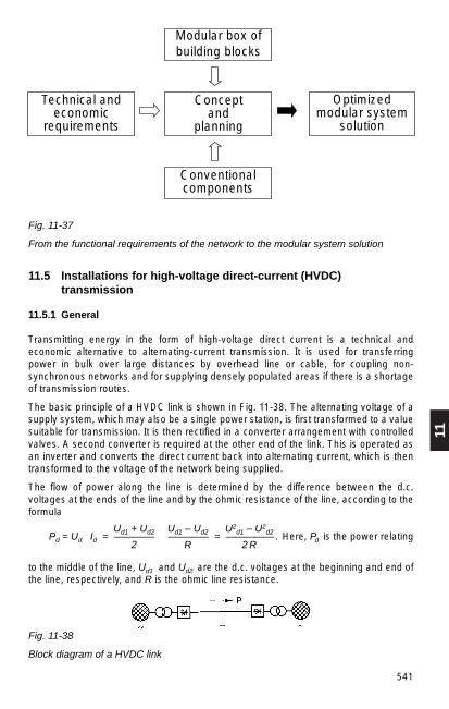

542
The frequency and phase shift of the two networks connected via the HVDC link haveno effect on the transmitted power and so transmission stability is no problem; networksof different frequency can be coupled without difficulty. With the three-phase bridgecircuit used in HVDC systems, the equation for the d.c. voltage of the converter is
uk IdUd = k Uv (cos α – — —– )2 IdN
where Uv is the valve-side voltage of the transformer, α the control angle of theconverter, uk the transformer’s relative impedance voltage, Id the d.c. transmissioncurrent and IdN the nominal d.c. transmission current.
Since the d.c. voltage can be altered almost instantly with the phase-angle controlsystem of the converters, the transmitted power can be varied very quickly and withinwide limits.
By changing control from rectifier to inverter mode (α > 90 °), it is possible to reversethe d.c. voltage and hence the energy flow direction, whereby the speed of reversal canbe adapted as necessary to the needs of the coupled networks. The quick response ofthe converter control can even be used to support stability by slightly modulating thetransmitted power to attenuate power fluctuations in one of the networks.
Because of delayed ignition and commutation overlap, line-commutated convertersrequire fundamental-frequency reactive power:
uk IdQ = Pd tan ϕ ; ϕ = arc cos (cos α – — —) where ϕ is the displacement angle of 2 IdN
the fundamental frequency.
The fundamental-frequency reactive power requirement of a HVDC converter at ratedload is about 50 to 60 % of the active power. By means of special control modes, it canbe varied within certain limits, so a HVDC converter can assist to maintain voltagestability in the three-phase network.
11.5.2 Selection of main data for HVDC transmission
The described technical characteristics of HVDC transmission are completelyindependent of the transmission distance and the kind of DC connection used,overhead line or cable; they are also valid for system interties in which rectifier andinverter are assembled in one station.
On the other hand, the main data of a HVDC link are very much influenced by the typeof conductor and transmission distance. With an overhead line, optimization of the linecosts and losses calls for the highest possible transmission voltage, a limit usuallybeing set by the line’s permissible surface voltage gradient. Countering this is the factthat the station costs, which increase with DC voltage, become less significant as thelength of line increases. Voltages of up to + 600 kV already exist.
Submarine cables with a transmission voltage of 450 kV and a length of 250 km arealready in use. Links more than twice as long and with transmission voltages of 500 kVare being planned.

11
543
For system interties, the main data are governed by optimization of the convertervalves. One chooses the rated current attainable with the largest available thyristorwithout paralleling, at present about 4000 A; the d.c. voltage then follows accordingly.
11.5.3 Components of a HVDC station
The basic circuit of a HVDC converter station is shown in Fig. 11-39.
Fig. 11-39
Basic circuit of a HVDC converter station:
1 A.C. switchgear 2 A.C. filter and reactive power
compensation 3 Converter transformers 4 Converter bridges 5 D.C. switchgear 6 Smoothing reactor and d.c. filter 7 D.C. line poles 1 and 2
The a.c. switchgear comprises not only the feeders to the converters, but also variousbranches for filter circuits and capacitor banks. The circuit-breakers must be capable offrequently switching large capacitive powers.
The a.c. filters are required to absorb current harmonics generated by the converter,and in this way, reduce distortion of the system voltage.
With 12-pulse converter units, it is customary to use tuned series resonant circuits forthe 11th and 13th harmonics together with broad-band high-pass filters for the higherharmonics. These a.c. filters also furnish some of the fundamental-frequency reactivepower needed by the converters. The remainder has to be provided by capacitor banks.At low system short-circuit outputs (SK less than 3 PD) it may be necessary to providesynchronous compensators instead of the capacitor banks.
The converter transformers convert the network voltage into the three-phase voltageneeded by the converter bridges. As Fig. 11-40 shows, a 12-pulse converter unitrequires two transformers connected differently to produce the two three-phasesystems with a phase offset of 30°. Converter transformers for HVDC are built with twoor three windings in single-phase or three-phase units. When the converter valvesoperate, the windings on the valve side are galvanically connected to a high d.c.potential, and the dielectric strength of their main insulation therefore has to bedesigned for high d.c. voltage. Windings and iron parts have to be speciallydimensioned owing to the high harmonic currents and the consequent leakage flux.
Fig. 11-40
Twelve-pulse converter unit, comprising two three-phasebridges connected in series on the d.c. side.

544
A 12-pulse converter unit consists of twelve valves. HVDC converter valves are madeup of thyristors. For high valve voltages, up to a hundred thyristors are connected inseries. To obtain a uniform voltage distribution, the thyristors have additional circuitryconsisting mainly of RC components. The heat sinks of the thyristors are cooled withforced-circulation air, oil or de-ionized water, the latter being the most common method.The valves are mostly ignited electronically by devices triggered by light pulses fedthrough fibre-optic cables. Converters with thyristors triggered directly by light are alsoused.
The d.c. switchgear has to perform a number of very different functions, depending onthe converter station’s design (cf. Fig. 11-41). The equipment used is mainly apparatuswhich has proved its performance in a.c. installations and been modified to meet theparticular requirements. The purpose of the bypass switch parallel with thetwelve-pulse unit is to commutate the station direct current when the unit is put into, ortaken out of, operation. The shunt disconnector enables the direct current to bediverted round a disconnected unit.
Ground faults on a d.c. line are cleared by controlling the voltage to zero. D.C. circuit-breakers are therefore not necessary with a straightforward HVDC link. MultiterminalHVDC systems can, however, benefit from HVDC breakers (Fig. 11-42) as theseimprove the system’s performance. A 500 kV HVDC circuit-breaker developed andtested by ABB has been proved in operation. The first multi-terminal HVDCtransmission system entered service in North America in early 1992.
The converter units each consist of two three-phase bridge arrangements with theirrespective transformers, one of which is in YyO connection, the other in Yd5connection. On the d.c. side, they are connected in series and on the a.c. side arebrought to a common circuit-breaker to form a twelve-pulse unit. If the station has to bedivided into more than two sections which can be operated independently, because ofthe maximum permissible power in the event of a fault, twelve-pulse units areconnected in series or parallel.
Fig. 11-41
One pole of a HVDC station with severalconverter units:a) Series connection, b) Parallel connectionof twelve-pulse units,1 Twelve-pulse converter unit, 2 Bypassbreaker, 3 Unit disconnector, 4 Shuntdisconnector, 5 Line disconnector

11
545
Fig. 11-42
500 kV HVDC circuit-breaker
a)Perspective arrangement b)Equivalent circuit diagram
1 Air-blast breaker2 Energy absorber
(ZnO arrester)3 Post insulators4 Capacitor bank5 Resonant-circuit reactor6 Post insulators7 Closing resistors (open
during tripping), added asnecessary
a)
b)
The smoothing reactors used on the d.c. side of HVDC stations smooth the directcurrent and limit the short-circuit current in the event of line faults. Their inductanceis usually between 0.1 and 1 H. They are mostly built in the form of an air-insulatedair-core reactor.
The d.c. voltage is filtered with DC filters. Their characteristics are matched to the dataof the transmission line, it being particularly important to avoid resonance at the 1st and2nd harmonics of the network frequency.
The lines for the two DC poles are usually carried on one tower. This is called a bipolarline. If there are special requirements for transmission reliability, two bipolar lines canbe used on one or two towers. In the second case, the full power of the remaininghealthy substation poles can be transmitted without earth return current even if a towerbreaks with appropriate switchovers where two line poles fail. Both cases exploit thefact that the lines can take a high thermal overload under the standard economicdesign.
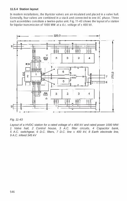
546
11.5.4 Station layout
In modern installations, the thyristor valves are air-insulated and placed in a valve hall.Generally, four valves are combined in a stack and connected to one AC phase. Threesuch assemblies constitute a twelve-pulse unit. Fig. 11-43 shows the layout of a stationfor bipolar transmission of 1000 MW at a d.c. voltage of ± 400 kV.
Fig. 11-43
Layout of a HVDC station for a rated voltage of ± 400 kV and rated power 1000 MW:1 Valve hall, 2 Control house, 3 A.C. filter circuits, 4 Capacitor bank, 5 A.C. switchgear, 6 D.C. filters, 7 D.C. line ± 400 kV, 8 Earth electrode line, 9 A.C. infeed 345 kV

11
547
Fig. 11-44
Section through the valve hall of a 500 MW HVDC converter station (400 kV):1 Converter valves, 2 Converter transformer, 3 Surge arrester.
A particularly compact station arrangement is obtained by placing the convertertransformers close to the valve hall so that their valve-side bushings pass through thewall. Fig. 11-44 shows the valve building and a single-phase three-winding convertertransformer. An interesting feature, technically and practically, is that the valves aresuspended from the hall ceiling.
11.6 Static var (reactive power) compensation (SVC)
11.6.1 Applications
In recent years, the control of reactive power has gained importance alongsideactive-power control. The use of mechanically switched choke and capacitor banks(see also Section 12.3.2 for the latter) has improved the reactive current balance in thenetworks. This has reduced transmission losses and kept stationary voltage deviationswithin the preset limits. In addition to this equipment, thyristor-controlled reactive-powercompensators (SVC = Static Var Compensator) have also been implemented. Theyreact virtually instantly and also offer the following advantages:
– very quick and infinitely variable reactive power conditioning,– improvement of voltage stability in weak networks,– increase of static and dynamic transmission stability and attenuation of power
swings,– enhancement of transmission capacity of lines,– quick balancing of variable non-symmetrical loads,

548
– lower transmission losses,– increased static and dynamic stability and reduced power fluctuations,– increased transmission capacity,– balancing of unsymmetrical loads,– continuous regulation of power factor.
Equipped with electronic components, SVC systems respond almost instantaneously.
Unlike the reactive-power compensation considered in Section 12.3.2, SVC systemsallow infinitely variable control across a whole band of reactive power. Also, the stabilityof networks can be improved.
11.6. 2 Types of compensator
Thyristor-Controlled Reactor (TCR)
An inductance (reactor bank) is controlled by thyristors as shown in Fig. 11-45. Thereactive power in this case is continuously changed between zero and the maximumvalue by conduction angle control of the thyristors. In many cases, this configuration isoperated together with a parallel-switched capacitor bank. This occurs when the entirereactive power correcting range also includes a capacitive component.
Features of this type are: – continuous correcting range, – no transient influence, – generation of harmonics.
To avoid harmonic overload of the network, the parallel capacitor banks must beupgraded to filter circuits.
Fig. 11-45
Thyristor-Controlled Reactor(TCR):1 Transformer, 2 Reactor coil,3 Thyristor valve, 4 Controlsystem
Thyristor-Switched Capacitor (TSC)
In this case, thyristor-switched capacitors (capacitor banks) are switched on or off, pathby path as shown in Fig. 11-46. To avoid transients, the thyristors are fired when thethyristor voltage is zero.

11
549
Fig. 11-46
Thyristor-Switched Capacitor(TSC):1 Transformer, 2 Thyristorvalve, 3 Damping coil, 4Capacitor, 5 Control system
Fig. 11-47
Thyristor-SwitchedCapacitor/Thyristor-Control-ed Reactor (TSC/ TCR)1 Transformer, 2 Reactorcoil, 3 Thyristor valve, 4 Damping coil, 5 Capacitor, 6 Control system
Features of this method are:
– stepwise control, – no transient interference, – no harmonics, – low losses.
Applying reactors instead of capacitors, again arranged as in Fig. 11-46, creates theThyristor-Switched Reactor method (TSR), which provides similar features to thoseabove.
Thyristor-Switched Capacitor/Thyristor-Controlled Reactor (TSC/TCR)
Often a combination of the two above methods provides the best solution.
A compensator as shown in Fig. 11-47 allows low-loss thyristor control of the entirecapacitive and inductive reactive-power correcting range. A smoothly varied output ofreactive power is obtained by altering the TCR’s firing angle. As soon as the TSC rangehas been compensated by the TCR, the capacitive path is disconnected and thecompensator functions as a reactor.
Features of this method are:
– continuous adjustment,– no transient interference,– slight generation of harmonics,– low losses.
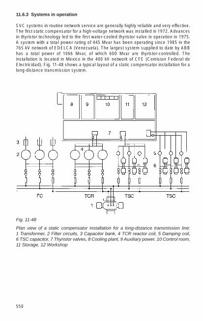
550
11.6.3 Systems in operation
SVC systems in routine network service are generally highly reliable and very effective.The first static compensator for a high-voltage network was installed in 1972. Advancesin thyristor technology led to the first water-cooled thyristor valve in operation in 1975.A system with a total power rating of 445 Mvar has been operating since 1985 in the765 kV network of EDELCA (Venezuela). The largest system supplied to date by ABBhas a total power of 1066 Mvar, of which 600 Mvar are thyristor-controlled. Theinstallation is located in Mexico in the 400 kV network of CFE (Comision Federal deElectricidad). Fig. 11-48 shows a typical layout of a static compensator installation for along-distance transmission system.
Fig. 11-48
Plan view of a static compensator installation for a long-distance transmission line:1 Transformer, 2 Filter circuits, 3 Capacitor bank, 4 TCR reactor coil, 5 Damping coil,6 TSC capacitor, 7 Thyristor valves, 8 Cooling plant, 9 Auxiliary power, 10 Control room,11 Storage, 12 Workshop

12
551
12 Transformers and other Equipment forSwitchgear Installations
12.1 Transformers
12.1.1 Design, types and dimensions
The purpose of transformers is to transfer electrical energy from systems of one voltageU1 to systems of another voltage U2.
Transformers can be differentiated according to their manner of operation (Fig. 12-1):
1. Power transformers, the windings of which are in parallel with the associatedsystems. The systems are electrically independent. The transfer of power is solelyby induction.
2. Autotransformers, the windings of which are connected in line (series winding RWand parallel winding PW). The throughput power SD is transferred partly byconduction and partly by induction.
3. Booster transformers; their windings are electrically independent, one winding beingconnected in series with one system in order to alter its voltage. The other windingis connected in parallel with its associated system (excitation winding EW). Theadditional power SZ is transferred purely inductively.
Fig. 12-1
Different types of transformers according to their manner of operation: a) Powertransformer, b) Autotransformer, RW Series winding, PW Parallel winding, c) Boostertransformer, EW Excitation winding, RW Series winding.
The following distinctions are made according to applications:
1. Transformers for the supply of power DIN EN 60076-1 (VDE 0532 Part 101), suchas distribution or main transformers, machine transformers and system-tietransformers,
2. Industrial transformers, such as welding transformers, furnace transformers,starting transformers and converter transformers,
3. Transformers for traction systems,
4. Special transformers, e.g. for testing, protection and control purposes.
Three-phase distribution transformers are covered by standards DIN 42500( HD 428.151) and DIN 42523 ( HD 538.151).

552
Transformers are divided into the following categories:
1. Class A: dry-type transformers (e.g. cast-resin transformers)Core and windings are not contained in an insulating liquid. Heat losses aredissipated direct to the ambient air, hence large surface area and low currentdensity. Up to approximately 20000 kVA and a maximum of 36 kV.ABB resin-encapsulated transformers of the RESIBLOC type are characterized byextremely high mechanical resistance of the windings because of fibre-glass-reinforced resin insulation and a very high resistance to fluctuations in temperature.
2. Class 0: oil-immersed transformersCore and windings are contained in mineral oil or similarly flammable synthetic liquidwith a fire point ≤ 300 °C which is simultaneously a coolant and insulating medium.
3. Class KCore and windings are contained in a synthetic liquid having a fire point > 300 °Cwhich is also a coolant and insulating medium. In construction, they are much likeoil-immersed transformers.
ABB uses silicone liquid for transformers with ratings of up to 10 000 kVA andservice voltages of up to 36 kV.Silicone liquid is flame-retardant and non-polluting. Other synthetic liquids (ester)with a fire point > 300 °C may be encountered, besides silicone liquid.
Askarel is no longer used as a coolant (environmental hazard).
Ratio variability
Ability to vary the ratio is important particularly with main transformers; it is used formatching the service voltage in the event of load fluctuations, for load distribution or foradjusting active and reactive current in interconnected networks, and for voltagecorrection with electric furnaces, rectifier stations, etc. In the simplest case, this is donewith the transformer dead, by altering the connection between winding sections with theaid of extra winding terminals, so-called tappings (normally + 4 % or + 5 %).
For stepwise variation under load, the tap changer (available in oil-insulated and drydesign) is preferably installed at the neutral end of the HV winding with powertransformers, and at the series winding with series transformers and autotransformers.
The tap changer, which connects the respective tappings while under load, consistsbasically of a load switch and a selector (or alternatively just a selector switch) with orwithout preselection.
The number of tappings and range of adjustment for power transformers of up to 40MVA and 110 kV are standardized (DIN 42515).
Continuous variation under load can be done with moving windings in the form of aspecial design as a rotary transformer or moving-coil regulator.

12
553
Fig. 12-2 shows an oil-insulated transformer (a) which has the currently preferredhermetically encapsulated design without expansion tank and a resin-encapsulatedtransformer (b) without enclosure. There are no standards for the dimensions ofdistribution transformers. Table 12-1 lists the main dimensions of a number ofdistribution transformers as examples of practical transformer designs with varyingtechnical data from the ABB production range.
Fig. 12-2
Structural types of distributiontransformers
a) hermetically encapsulated oil-insulated transformers
b) RESIBLOC resin-encapsulatedtransformers without enclosure
Table 12-1
Main dimensions of ABB distribution transformers, as shown in Fig. 12-2a) Oil-insulated transformers, hermetically encapsulated b) RESIBLOC resin-encapsulated transformers without enclosure
Tech. data Main dimensions in mma b c d
a) 10 kV, 250 kVA, 4% 1170 740 1440 520 20 kV, 250 kVA, 4% 1170 770 1510 520 10 kV, 630 kVA, 6% 1420 870 1440 670 20 kV, 630 kVA, 6% 1460 930 1525 670
b) 10 kV, 250 kVA, 4% 1110 660 1250 520 20 kV, 250 kVA, 4% 1350 660 1560 520 10 kV, 630 kVA, 6% 1500 810 1360 670 20 kV, 630 kVA, 6% 1560 810 1820 670
a)
b)
bda
d
c
ad
c
bd

554
12.1.2 Vector groups and connections
Vector groups
The vector group denotes the way in which the windings are connected and the phaseposition of their respective voltage vectors. It consists of letters identifying theconfiguration of the phase windings and a number indicating the phase angle betweenthe voltages of the windings.
With three-phase a.c. the winding connections are categorized as follows:
a) Delta (D, d)b) Star (Y, y)c) Interconnected star (Z, z)d) Open (III, iii)
Capital letters relate to the high-voltage windings, lower-case letters to the medium andlow-voltage windings. The vector group begins with the capital letter. In the case ofmore than one winding with the same rated voltage, the capital letter is assigned to thewinding with the highest rated power; if the power ratings are the same, to the windingwhich comes first in the order of connections listed above. If the neutral of a winding instar or interconnected star is brought out, the letter symbols are YN or ZN, or yn or zn,respectively.
To identify the phase angle, the vector of the high-voltage winding is taken as areference. The number, multiplied by 30° denotes the angle by which the vector of theLV winding lags that of the HV winding. With multi-winding transformers, the vector ofthe HV winding remains the reference; the symbol for this winding comes first, the othersymbols follow in descending order according to the winding’s rated voltages.
Example:
For a transformer with three power windings (HV windings 220 kV in neutral connectionwith brought-out neutral, MV winding 110 kV in neutral connection with brought-outneutral, and LV winding 10 kV in delta connection), if the vectors of the neutral voltageof HV and MV winding are in phase and the vector of the neutral voltage of theLVwinding lags behind them by 5 · 30 = 150°, the identifying symbols are:
YN, yn 0, d 5.
Preferred connections
Yyn 0 for distribution transformers. The neutral point can be loaded continuouslywith up to 10 % of the rated current, or with up to 25 % of the rated current fora maximum of 1.5 hours. Example: for connecting arc suppression coils.
YNyn 0 with compensating winding, used for large system-tie transformers. Theneutral point can be loaded continuously with the rated current.
YNd 5 intended for machine and main transformers in large power stations andtransformer stations. The neutral point can be loaded with the rated current.Arc suppression coils can be connected (delta winding dimensioned for themachine voltage).
Yzn 5 for distribution transformers, used up to approx. 250 kVA for local distributionsystems. The neutral point can be loaded with the rated current.

12
555
Dyn 5 for distribution transformers above approx. 315 kVA, for local and industrialdistribution systems. The neutral point can be loaded with the rated current.
Ii 0 for single-phase transformers, intended for traction power supply or forthree-phase banks with very high voltages and powers.
If single-phase transformers are combined to form three-phase banks, the switchgear,instrument transformers and conductor cross-sections must be designed for the voltageand current ratings given in Table 12-2.
Identification and arrangement of terminals
Terminations of the windings (coils) brought out in the same winding sense are denoted1U1,1V1,1W1 for the primary windings and 2U1, 2V1, 2W1 for the secondary windings.The terminations at the other ends of the windings, brought out in the inverse windingsense, are designated 1U2, 1V2, 1W2 for the primary windings and 2U2, 2V2, 2W2 forthe secondary windings.
As a rule, the terminals of a transformer (1U,1V,1W for the primary side and 2U, 2V, 2Wfor the secondary side) are arranged from right to left as viewed from the low-voltageside, with their inscriptions visible from the low-voltage side, Fig. 12-3.
Fig. 12-3
Identification and arrangement of theterminals of a transformer (in accordancewith DIN 42402)
1W 1V 1U 1N2W 2V 2U 2N
Table 12-2
Values of Ur and Ir for transformers of connection III iii
Connection Rated voltage Rated currentof windings Ur Ir
Star 3 Uph Iph
Delta Uph 3 Iph
Uph phase (conductor/earth) voltage, Iph phase (winding) current.

556
12.1.3 Impedance voltage, voltage variation and short-circuit current withstand
Voltage drops
The impedance voltage Ukr is defined as that voltage having the rated frequency whichmust be applied to the primary side of a transformer so that the rated current Ir flowswhen the secondary terminals are short-circuited. Since only the short-circuitimpedance is present in the circuit,
Ukr = 3 · Ir · Zk.
The rated impedance voltage is usually stated as a percentage of the voltage rating Ur
of the winding to which the voltage is applied:
Ukrukr = — · 100 %.Ur
The impedance voltage is composed of the ohmic voltage drop (UR, uR) which is inphase with the current, and the reactive voltage (Ux, ux), which leads the current in timeby 90°.
Ohmic voltage drop:
Pkr Impedance losses at rated poweruRr = — · 100 % = ——————————————— 100 %.
Sr rated power
Reactive voltage:
uXr = ukr2 – uRr
2 .
In the case of a partial load, the short-circuit voltage Uk is proportional to the load on thetransformer:
I Suk = ukr – = ukr –
I r Sr
For distribution transformers, according to DIN 42500 a rated impedance voltage ukr isallocated to each power rating Sr, Table 12-3.
Table 12-3
Rated impedance voltage ukr
Rated output Sr in kVA1) ukr
50 (63) 100 160 (200) 250 (315) 400 (500) 630 4 %630 (800) 1000 (1250) 1600 (2000) 2500 6 %
1) Rated outputs not in brackets are preferred.

12
557
Transformers with a rated impedance voltage u kr = 4 % are used mainly in distributionnetworks in order to keep the voltage drop small.
Transformers with a rated impedance voltage u kr = 6 % are preferably to be used inindustrial networks and in high-power distribution networks in order to limit the short-circuit stress. The rated impedance voltages of medium-size and large transformers areeven higher so as to achieve sufficient short-circuit strength.
Voltage variation
The voltage variation between no-load and a symmetrical load of any magnitude for anycos ϕ can be calculated from the rated impedance voltage and the impedance lossesat rated load. It is denoted uϕ, and referred to the rated voltage.For a given part load a = S/Sr and a given power factor cos ϕ,
1 (a · uϕ )2 1 (a · u ϕ)4
uϕ = a · uϕ + – · ———— + – · ———— + …1)
2 102 8 106
whereuϕ = uRr · cos ϕ + uXr · sin ϕ
anduϕ = uRr · sin ϕ – uXr · cos ϕ
The actual voltage at the terminals on the output side of the loaded transformer willthen be
uϕUa = Ur (1 – ——— )100 %
Example:
Find the full-load voltage Ua for a transformer with rated load on the output side atcos ϕ = 0.8 (sin ϕ = 0.6).
Rated output: Sr = 2500 kVA, Impedance losses: Pkr = 24 kW,Impedance voltage: ukr = 6 %.
Pkr 24 kWuRr = — · 100 % = ——–—— 100 % = 0.96 %
Sr 2500 kVA
uxr = ukr2 – uRr
2 = 62 – 0.962% = 5.923 %
uϕ = uRr cos ϕ + uxr sin ϕ = 0.96 · 0.8 + 5.923 · 0.6 = 4.32 % uϕ = uRr sin ϕ – uxr cos ϕ = 0.96 · 0.6 – 5.923 · 0.8 = – 4.16 %
1 (uϕ )2 1 (– 4.16)2
uϕ = uϕ + — —— = 4.32 + — · ————— = 4.4 %.2 102 2 102
uϕUa = Ur (1 – ———— ) = 0.965 · Ur.100 %
1) If ukr < 20 % the third summand can be disregarded. The second summand may also bedisregarded if ukr < 4 %.

558
Short-circuit current and its limitation
The criterion for the short-circuit is a reference impedance composed of theimpedances of the network (ZQ) and transformer (Zk). This is
Ur IkIk3p = —————–— ≈ ——— · 100 %.3 |ZQ + Zk | ukr %
With distribution transformers of ratings up to 3150 kVA and ZQ ≤ 0.05 · Zk, the networkimpedance ZQ can usually be disregarded.
The short-circuit impedance limits the short-circuit current. Thermal stress is governedby the sustained short-circuit current Ik. The maximum permissible short-circuit durationis 2 s as per DIN 57532-5 (VDE 0532 Part 5), unless otherwise specified by thecustomer.
With transformers of vector groups Dy and Yd, the single-phase sustained short-circuitcurrent is about the same as the three-phase value. At windings in interconnected starconnection, the single-phase sustained short-circuit current can reach roughly 1.4times the three-phase value, as its zero-sequence impedance is usually very small.
Table 12-4
Reference impedances for two-winding transformers (to VDE 0532 Part 5)
Rated power Typical Maximum Typical values ofvalues system voltage reference systemof zk fault level SkQ
1)
(or ukr)kVA % kV MVA
7.2 12 17.5
to 630 4.0 and 24 500
from 630 to 1 250 5.0 136 1 000
from 1 250 to 3 150 6.25 152 and 172.5 3 000
from 3 150 to 6 300 7.15 100 and 123 6 000
from 6 300 to 12 500 8.35 145 and 170 10 000
from 12 500 to 25 000 10.0 245 20 000
from 25 000 to 200 000 12.5 300 30 000
420 40 000
1) If not specified
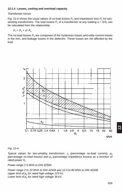
12
559
Fig. 12-4
Typical values for two-winding transformers. i0 (percentage no-load current), p0
(percentage no-load losses) and pk (percentage impedance losses) as a function ofrated power Sr.
Power range 2.5 MVA to DIN 42500
Power range 2 to 10 MVA to DIN 42504 and 12.5 to 80 MVA to DIN 42508 Upper limit of pk for rated high voltage 123 kV,Lower limit of pk for rated high voltage 36 kV.
12.1.4 Losses, cooling and overload capacity
Transformer losses
Fig. 12-4 shows the usual values of no-load losses P0 and impedance loss Pk for two-winding transformers. The total losses Pv of a transformer at any loading a = S/Sr canbe calculated from the relationship:
Pv = P0 + a2 Pk.
The no-load losses P0 are composed of the hysteresis losses and eddy-current lossesin the iron, and leakage losses in the dielectric. These losses are not affected by theload.
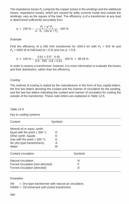
560
The impedance losses Pk comprise the copper losses in the windings and the additionallosses. Impedance losses, which are caused by eddy currents inside and outside thewindings, vary as the square of the load. The efficiency η of a transformer at any loadis determined sufficiently accurately from
P0 + a2 Pkη = 100 % – —————————— · 100 % a · Sr · cos ϕ + P0
Example
Find the efficiency of a 250 kVA transformer for 20/0.4 kV with P0 = 610 W and Pk = 4450 W at half-load (a = 0.5) and cos ϕ = 0.8.
0.61 + 0.52 · 4 45η = 100 % – ———————————— · 100 % = 98.29 %.
0.5 · 250 · 0.8 + 0.61
In order to assess a transformer, however, it is more informative to evaluate the lossesand their distribution, rather than the efficiency.
Cooling
The method of cooling is stated by the manufacturer in the form of four capital letters,the first two letters denoting the coolant and the manner of circulation for the winding,and the last two letters indicating the coolant and manner of circulation for cooling theoutside of the transformer. These code letters are explained in Table 12-5.
Table 12-5
Key to cooling systems
Coolant Symbols
Mineral oil or equiv. synth.liquid with fire point ≤ 300 °c OOther synth. Iiquids KGas with fire point > 300 °C GAir (dry-type transformers) AWater W
Coolant circulation Symbols
Natural circulation NForced circulation (non-directed) FForced circulation (directed) D
Examples
AN = Dry-type transformer with natural air circulation, ONAN = Oil-immersed self-cooled transformer.

12
561
Overload capacity to DIN 57536 (VDE 0536)
The maximum time for which transformers can be overloaded at a given bias load andcoolant temperature is shown in Fig. 12-5 for air-cooled oil-immersed transformers inthe case of two different loads recurring regularly in a 24-hour cycle.
In the diagram:
K1 Initial load as a proportion of rated power,K2 Permitted overload as a proportion of rated power (normally > 1),t Duration of K2 in h,Θa Coolant temperature in °C.
Hence
S1 S2 K2 S2K1 = —; K2 = —; — = —Sr Sr K1 S1
Here, S1 is the initial load, S2 the maximum permitted load and Sr the rated power.Under normal circumstances, K2 should not exceed 1.5.
Example:
Transformer 1250 kVA with ONAN cooling. Bias load 750 kVA. What is the maximumpermitted load over 4 hours at 20 °C?
K1 = 0.6; t = 4 h. Fig. 12-5a yields K2 = 1.29.
S2 = K2 · Sr = 1.29 · 1250 kVA = 1612 kVA.
Fig. 12-5
Transformer with ONAN and ONAF cooling. Values of K2 for given values of K1 and t(in hours), a) Θa = 20 °C, b) Θa = 30 °C
a) b)
K1 K1
K2K2
K2
K1= 1,8

562
For a given case of transformer loading, the power rating Sr can be calculated from:
S1 S2Sr = — = —K1 K2
Example:
At Θa = 30 °C, a transformer with ONAN cooling is to run for 4 hours at 450 kVA andotherwise at 250 kVA. What power rating is required?
S1 = 250 kVA, t1 = 20 h; S2 = 450 kVA, t2 = 4 h.
S2 450 K2— = ––– = 1.8 = —S1 250 K1
From Fig. 12-5 b for K2/K1 = 1.8 when t = 4 h: K1 = 0.65; K2 = 1.17.
450 250Sr = ––– = ––– = 385 kVA → 400 kVA.
1.17 0.65
12.1.5 Parallel operation
Transformers are in parallel operation if they are connected in parallel on at least twosides. A distinction is made between busbar interconnection and networkinterconnection. The following conditions must be satisfied in order to avoid dangeroustransient currents:
1. vector groups should have the same phase angle number; terminals of the samedesignation must be connected together on the HV and LV sides; Exception: Phaseangle numbers 5 and 11 (Table 12-6);
2. the ratios should be as similar as possible, i.e. the same rated voltages on the HVand LV sides;
3. approximately the same impedance voltages uk maximum permissible discrepancies± 10 %. In the event of larger differences, an inductance (reactor) can be connectedahead of the transformer with the lower impedance voltage.
4. rated output ratio smaller than 3:1.
Table 12-6 Parallel operation of transformers with phase angle numbers 5 and 11
Phase angle Phase angle Connection to conductors Connection to conductorsnumber number HV side LV siderequired available L1 L2 L3 L1 L2 L3
5 5 1U 1V 1W 2U2 2V2 2W2
5 11 1U 1W 1V 2W1 2V1 2U1or 1W 1V 1U 2V1 2U1 2W1or 1V 1U 1W 2U1 2W1 2V1
11 11 1U 1V 1W 2U1 2V1 2W1
11 5 1U 1W 1V 2W2 2V2 2U2or 1W 1V 1U 2V2 2U2 2W2or 1V 1U 1W 2U2 2W2 2V2

12
563
Load distribution of parallel transformers with different rated impedance voltages
Transformers connected in parallel assume a partial load such that all the transformershave the same average impedance voltage. If the impedance voltage of a transformeris referred to an output other than its rated output, its magnitude varies in accordancewith the output. A 100 kVA transformer with ukr = 4 % has at 60 kVA an impedancevoltage uk of 0.6 · 4 = 2.4%.
Example:
transformer 1: Sr1 = 100 kVA, ukr1 = 4.0 %transformer 2: Sr2 = 250 kVA, ukr2 = 6.0 %transformer 3: Sr3 = 500 kVA, ukr3 = 4.5 %
total S = 850 kVA
We have:
S Sr1 Sr2— = —— + —— + …uk uk1 uk2
The resultant impedance voltage is then:
S 850uk = —————–—————— = —————–—————— = 4.78 %
Sr1 Sr2 Sr3 100 250 500—— + —— + —— —— + —— + ——ukr1 ukr2 ukr3 4 6 4.5
The power assumed by the individual transformers is:
uk 4.78S1 = Sr1 —— = 100 · —–— = 120 kVA
ukr1 4
uk 4.78S2 = Sr2 —— = 250 · —–— = 199 kVA
ukr2 6
uk 4.78S3 = Sr3 —— = 500 · —–— = 531 kVA
ukr3 4.5
Stot = S1 + S2 + S3 = 120 kVA
Transformer 1 is thus overloaded by 20 % and transformer 3 by 6 %. Since theindividual transformers should not be subjected to overload, the transformers may onlyassume a partial load such that the impedance voltage of each is uk = 4 %, as in thecase with transformer 1. Therefore,
4S1 = 100 · – = 100 kVA
4

564
4S2 = 250 · – = 167 kVA
6
4S3 = 500 · –— = 444 kVA
4.5
Stot = S1 + S2 +S3 = 711 kVA
If this output is not sufficient, another 160 kVA transformer with ukr = 4 % will have to beinstalled.
Effect of dissimilar transformation ratios of transformers connected in parallel
Dangerous transient currents can occur if transformers with different voltages betweentaps are operated in parallel. Disregarding any dissimilarity in impedance phase angleϕk, the voltage difference ∆ u proportional to the difference in ratio drives through bothsides a circulating current of
∆ uIa = ————————
uk1/Ir1 + uk2/Ir2
If, for example, uk1 = uk2 = 6 %, Ir1 = 910 A, Ir2 = 1445 A und ∆ u = 4 %, then
4 %Ia = ——————————————— = 377.34 A.
6 % / 910 A + 6 % / 1445 A
This balancing current is superimposed on the transformer load currents that aresupplied to the network. It is added to the current of that transformer which has thegreater secondary no-load voltage.
12.1.6 Protective devices for transformers
Overcurrent time relays respond to short circuits; they trip the circuit-breakers.
Thermal relays respond to unacceptable temperature rises in the transformer, andsignal overloads.
Make-proof percentage differential relays detect internal short circuits and faults,including those on lines between the current transformers; they trip the appropriatetransformer breakers, but do not respond to the inrush current of a sound transformer.
Buchholz relays detect internal damage due to gassing or oil flow; they signal minordisturbances and trip the breaker if the trouble is serious.
Temperature monitors signal when a set temperature is reached, or trip circuit-breakers.
Dial-type telethermometers indicate the temperature in the transformer’s topmost oillayer with maximum and minimum signal contacts.
Oil level alarms respond if the oil level is too low.
Oil flow indicators detect any disruption in the circulation in closed-circuit cooling andtrigger an alarm.
Airflow indicators detect any break in the flow of forced-circulation air, and trigger analarm.

12
565
12.1.7 Noise levels and means of noise abatement
Since transformers are located in or near residential areas, the noise they producemust be determined so as to assess the need for any countermeasures.
The noise of transformers is defined as the A-weighted sound pressure level measuredin dB (A) at a specified measuring surface with a sound level meter, and then convertedto a sound power level with the following formula:
LWA = LPA + LS
In which:
LWA A-weighted sound power level in dBLPA A-weighted sound pressure level in dBLS Measuring-surface level in dB
The measurements must be performed according to DIN EN 60551 (VDE 0532 Part 7).For transformers with water cooling or fan-less air cooling, at least 6 measurementsmust be taken at a distance of 0.3 m from the surface of the transformer. Fortransformers with other cooling systems, the relevant measurement regulations as perDIN EN 60551 (VDE 0532 Part 7) apply.
Table 12-7
A-weighted sound power level in dB (A) for transformers up to a rated power of 2.5 MVA
Rated power Oil-insulated transformers Resin-encapsulatedas per DIN 42500 transformers
kVA List A’ B’ C’ as per DIN 425231)
50 55 50 47 –100 59 54 49 59 (51)160 62 57 52 62 (54)250 65 60 55 65 (57)400 68 63 58 68 (60)630 70 65 60 70 (62)
1 000 73 68 63 73 (65)1 600 76 71 66 76 (68)2 500 81 76 71 81 (71)
1) Values in parentheses for the reduced series
The causes and effects of the noise produced by transformers and their coolingsystems are so diverse that it is not possible to recommend generally applicable noiseabatement measures. Each case must be carefully investigated as necessary.

566
Possible measures include:
Actions by the transformer manufacturer to reduce airborne and structure-borne noise.
Structural measures against airborne noise, e.g. sound-absorbent walls or enclosures.
Anti-vibration treatment of the foundations to reduce transmission of structure-bornenoise, e.g. spring-mounted supporting structure.
12.2 Current-limiting reactors EN 60289 (VDE 0532 Part 20)
12.2.1 Dimensioning
Current-limiting reactors (series reactors) to DIN VDE 0532, Part 2 are reactancesemployed to limit short-circuit currents. They are used when one wishes to reduce theshort-circuit power of networks or installations to a value which is acceptable withregard to the short-circuit strength of the equipment or the breaking capacity of thecircuit-breaker.
Since the reactance of a series reactor must remain constant when short-circuitcurrents occur, only the air-core type of construction is suitable1). If iron cores wereused, saturation of the iron brought about by the short-circuit currents would cause adrop in the inductance of the coil, thus seriously reducing the protection against shortcircuits.
Voltage drop and voltage variation
The rated impedance is the impedance per phase at rated frequency. The resistanceof a current-limiting reactor is negligible and in general, amounts to not more than some3 % of the reactance XL.
The rated voltage drop ∆ Ur is the voltage induced in the reactor when operating withrated current and rated reactance:
∆ Ur = Ir · XL
When referred to the nominal voltage of the system, the rated voltage drop is denoted∆ ur and usually stated in %:
∆ Ur · 3∆ ur = ————— 100 %.
Un
Example:
A reactor in a three-phase system with a rated voltage of 10 kV has a reactance of 5 %.Its rated current is 400 A. This statement indicates that the voltage drop at the reactoris 5 % of the system phase-to-earth voltage. The absolute value in volts is
∆ Ur · Un 5 % · 10 000 V∆ Ur = —————— = ————————— = 289 V.
3 · 100 % 3 · 100 %
1) Air-core reactors can cause the frequency of the recovery voltage to assume extremely high values(150 to 250 kHz). Reduction of these natural frequencies to the values for circuit-breakers definedby VDE 0670 Part 104 can be achieved by fitting capacitors.
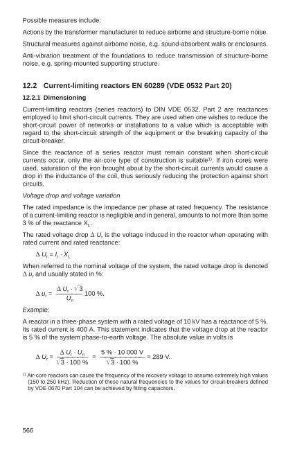

12
567
According to Fig. 12-6, for a given load a= I/Ir and a given power factor cos ϕ
Uϕ = a · ∆ Ur · cos (90 ° – ϕ)
or uϕ = a · ∆ ur · sin ϕ.
Example:
At a power factor of cos ϕ = 0.8 and rated current, a reactor with ∆ ur = 6 % causes avoltage variation in the network of uϕ = 6 % • 0.6 = 3.6 %.
If large motors are connected after reactors and the current ratings of the motor and thereactor are of the same order of magnitude, account must be taken of the voltage dropdue to the large starting current of the motor. The drop must not be so large as toendanger the safe run-up of the motor.
Inherent power and throughput power
The inherent power of a reactor is the product of the voltage drop ∆ Ur and the ratedcurrent Ir.
SE = 3 · ∆ Ur · Ir (three-phase).
The throughput of a reactor is the product of the line-to-earth voltage Un/3 and therated current Ir.
SD = 3 · Un · Ir (three-phase).
Selection of a current-limiting reactor
If the given short-circuit power Sk1 of a grid system is to be reduced to a value of Sk" byfitting a reactor, its required percentage rated voltage drop is
Sk1 – Sk2∆ ur = 1.1 · 100 % · SD · ————— .Sk1 · Sk2
For given values of reactance and current, the voltage variation Uϕ in the network, i.e.the difference between the network voltage before and after the reactor, is alsodependent on cos ϕ, Fig. 12-6. Thus, whereas the voltage difference Uϕ across thereactor is small under normal operating conditions, it increases in the event of a shortcircuit
1. in proportion to the short-circuit current and
2. with the increase in phase displacement angle under fault conditions.
Fig. 12-6
Vector diagram of a reactor:
a) Normal operationb) Short-circuit operationU1 System voltage before reactorU2 System voltage after reactorUϕ Voltage variation in system

568
Example:
Un = 6 kV, lr = 600 A;Sk1 = 600 MVA, Sk2 = 100 MVA;
600 MVA – 100 MVA∆ ur = 1.1 · 100 % · 3 · 6 kV · 0.6 kA ———————————— = 5.72 %.600 MVA · 100 MVA
In practice, one will select the next-highest standardized value, 6 % in this instance.
If the short-circuit power Sk1 before a reactor is given, and its percentage rated voltagedrop is ∆ ur, the short-circuit power Sk2 after the reactor is:
1.1 · 100 % · SD · Sk1Sk2 = ———————————————.1.1 · 100 % · SD + ∆ ur · Sk1
Taking the values of the example above, this yields:
1.1 · 100 % · 3 · 6 kV · 0.6 kA · 600 MVASk2 = ———————————————————————————— = 96 MVA.
1.1 · 100 % · 3 · 6 kV · 0.6 kA + 6 % · 600 MVA
Fig. 12-7
The most common reactor connections: a) Feeder connection, b) Tee-off connection, c) Busbar sectionalizer connection.
In power stations with a high short-circuit power, it is usual to fit busbar sectionalizingreactors together with bypass circuit-breakers, as shown in c). In this way, a permanentconnection is established between the busbars, although in the event of a fault, whenthe circuit-breaker opens, the short-circuit power is limited approximately to that of theindividual systems.
It is even better to use Is-limiters (Section 8.1.6) instead of circuit-breakers forbypassing reactors, because these devices interrupt the bypass without any delay andtherefore prevent hazardous peak current values from occurring.
12.2.2 Reactor connection
The scheme shown in Fig. 12-7 under a), with the reactors in the tee-offs, is the onemost commonly used. The circuit shown in b), with the reactors in the feeder, is oftenchosen for reasons of saving space. For the same degree of protection, the costs ofpurchase and operation are higher than with reactors in the branches.

12
569
12.2.3 Installation of reactors
When installing reactors, care must be taken to ensure that the heat losses occurringduring operation are dissipated by adequate ventilation. As a rough estimate, one canassume a fresh air requirement of 4 to 5 m3/min per kilowatt of heat loss. The air flowcross-sections necessary in the rooms can be calculated more accurately using themethod described in Section 4.4.2 for transformers.
Care must also be taken that reactors are situated sufficiently far away fromneighbouring metal parts to ensure that these are not heated excessively by eddycurrents.
Reactors should not be situated at distances of less than 500 mm from constructionalitems of steel, and steel reinforcement in ceilings, floors and walls. If the floor issteel-reinforced, the reactor must be placed on a concrete pedestal, Fig. 12-8.
Fig. 12-8
Installation of a current-limiting reactor:Dm mean diameter of reactor, a distancebetween centre line of reactor and metalitem1 Steel-reinforced wall2 Reinforcing bars(dimensions in mm)
With cell enclosures of non-magnetic materials (aluminium alloys), the minimumclearance for the highest equipment voltage in question (DIN VDE 0101) is sufficient.Closed structures (short-circuit loops) with a good electrical conductivity must beavoided in the vicinity of strong magnetic fields. If necessary, the short-circuit loopshould be split and the junction joined by means of non-conducting material to preventexcessive heating by circulating currents.
If one is forced to use magnetic materials, the distance between reactor and metalstructure should be selected so that under rated conditions, the root-mean-squarevalue of the magnetic field strength does not exceed 20 A/cm. The field strength iscalculated as
Ir · w · DmH = 0.1 · ————–— a2
Here, Ir rated current in A, w number of turns in reactor, for Dm and a, see Fig. 12-8.

570
12.3 Capacitors
12.3.1 Power capacitors
The term power capacitor is chiefly applied to capacitors having a rated frequency of 50 or 60 Hz which compensate the reactive power at points of heavy demand in publicand industrial networks. This general designation also includes “furnace capacitors”and “medium-frequency capacitors”, which cover the high reactive power requirementof melting furnaces and inductive heating coils, and also “welding machine capacitors”and “fluorescent lamp capacitors” used for compensating welding transformers and theballasts of fluorescent lamps. The design of power capacitors is regulated by thefollowing standards: DIN VDE 0560-1 (VDE 0560 Part 1), and DIN EN 60831-1 (VDE0560 Part 46) – self-restoring up to 1000 V –, DIN EN 60931-3 (VDE 0560 Part 45) –non-self-restoring up to 1000 V – and DIN EN 60871-1 (VDE 0560 Part 410) – over1000 V –.
The reactive power of a capacitor is determined by its capacitance, the rms value of theoperating voltage and the system frequency:
Qc = U 2 · ω · C.
The rated power of a capacitor as stated on its nameplate is always in relation to itsrated voltage Ur and rated frequency fr.
In three-phase networks, the capacitors, always three of the same size, are connectedin either star or delta. If
C1 is the capacitance in one phase with star connection, and
C12 is the capacitance in one phase with delta connection,
then for the same reactive power:
C1 = 3 C12.
The temperature range for power capacitors is specified by the temperature classes(DIN EN 60831-1, Table 1). The following temperature values are applicable for thepermissible ambient temperatures, e.g. for the -25°C class (preferred temperatureclass),
maximum: 50 °C,max. average over 24 h: 40 °C,max. average over 1 year: 30 °C,minimum: -25 °C.
Voltage and frequency increases and total harmonic distortion of the voltage or thecurrent place additional stress on capacitors.
Capacitors must be able to carry continuously 1.3 times the current flowing withsinusoidal rated voltage and frequency at an ambient air temperature corresponding toits temperature class. With this loading, the voltage must not be higher than 1.1 Ur, noaccount being taken of transient overvoltages.
If the limiting conditions stated above are exceeded, the chosen capacitor must bereplaced by one with a higher voltage rating and a rated power according to theequation
Qr2 = Qr1 (Ur2/Ur1)2.

12
571
Where such a capacitor is directly connected to the system, the connection lines andthe switching and protection devices must be rated correspondingly higher. However,this does not ensure that the system conditions are compatible for other consumers.For this reason, in most cases it is better to include inductor-capacitor units.
When selecting the switchgear apparatus, protective devices and conductors, attentionmust be paid to the possibility of overloading mentioned above. Taking account of thepermissible difference in capacitance, this is (1.1 · 1.3) = 1.43 times the capacitorcurrent rating.
HRC fuses serve only as short-circuit protection and do not provide adequateprotection against overcurrents. Bimetal and secondary thermal relays arerecommended as thermal protection for capacitor banks of above 300 kvar. The trippingcurrent of these relays should be set to 1.43 times the rated current of the capacitor(capacitor bank). Protection by means of overcurrent relays does not at the same timeprovide protection against overvoltages.
All capacitor installations must be connected direct to a means of discharge, withoutintervening isolators or fuses. Low-voltage capacitors must discharge to a residualvoltage ≤ 75 V within 3 minutes. A maximum discharge time of 10 minutes is stipulatedfor high-voltage capacitors.
The residual voltage at the capacitator must not exceed 10 % of the nominal voltagebefore switching on.
When capacitors are connected in star, the neutral point must not be directly earthed.Earthing via surge arresters (blow-out fuses) is permissible.
For installation, connection and special protective measures, note must be taken ofspecifications DIN VDE 0100, DIN VDE 0101, DIN VDE 0105 and the “Technicalconnection requirements for power installations” of VDEW.
12.3.2 Compensation of reactive power
Only the active power produced by the active current is utilized at the point ofconsumption. The reactive power produced by the reactive current does not contributeto the conversion into useful power and is therefore not counted by the active powermeter. However, the reactive power has an unfavourable effect on the electricalequipment in that it constitutes an additional load on generators, transformers andconductors. It gives rise to additional voltage drops and heat losses.
Static reactive-power (var) compensation in systems with the aid of thyristors is dealtwith in Section 11.6.

572
It is economically sound to draw the reactive power from capacitors, Fig. 12-9. Theseare located in the vicinity of the largest reactive loads (motors and transformers) inorder to relieve the transmission networks, including transformers and generators, fromthe corresponding share of the reactive current. If the capacitors are properlypositioned, by reducing the reactive current in this way, it is possible in many instancesto connect additional loads to existing supply systems without having to increase thepower or extent of the network.
Fig. 12-10 shows the reactive power before compensation with Q1 = P · tan ϕ1 andafter compensation with Q2 = P · tan ϕ2 , where ϕ2 is the phase displacement angle ofthe desired cos ϕ2. The capacitor rating required for this is
Qc = P · (tan ϕ1 – tan ϕ2)
Table 12-8 provides an aid to calculation.
Example:
A motor draws active power of P = 60 kW from a system at cos ϕ = 0.6. Since tan ϕ = 1.333, the reactive power consumed by the motor is Q = 60 · 1.333 = 80 kvar.
If one wishes to compensate this reactive power to cos ϕ = 1 by means of a capacitor,the capacitor must also have a power rating of 80 kvar. In most cases, such extensivecompensation, to cos ϕ = 1, will not be necessary. If a power factor of cos ϕ = 0.8 issufficient in this particular instance, the capacitor rating can be calculated as follows:
cos ϕ1 = 0.6; tan ϕ1 = 1.333; desired cos ϕ2 = 0.8; tan ϕ2 = 0.750:
Qc = P (tan ϕ1 – tan ϕ2) =
= 60 (1.333 – 0.75) = 60 · 0.583 = 35 kvar.
Thus the capacitor only has to be sized for this reactive power.
Fig. 12- 10
Power vector diagram for determining the capacitor rating Qc
required to compensate reactive power; Index 1: Valueswithout compensation, Index 2: Values with compensation.
Fig. 12-9Active and reactive currents in anelectrical installation:a) uncompensated, b) compensated with capacitors. With full compensation, thegenerator G supplies only thecurrent Iw for the purely active loadR, and active current Icw for thecapacitor loss resistance Rc.
a) b)

12
573
Table 12-8
To determine the factor (tan ϕ1 – tan ϕ2) for calculating reactive power at different powerfactors
Existing Desired power factor cos ϕ2
cos ϕ1 0.7 0.75 0.8 0.82 0.84 0.86 0.88 0.9 0.92 0.94 0.98
0.30 2.16 2.30 2.42 2.48 2.53 2.59 2.65 2.70 2.76 2.82 2.890.35 1.66 1.80 1.93 1.98 2.03 2.08 2.14 2.19 2.25 2.31 2.380.40 1.27 1.41 1.54 1.60 1.65 1.70 1.76 1.81 1.87 1.93 2.00
0.45 0.97 1.11 1.24 1.29 1.34 1.40 1.45 1.50 1.56 1.62 1.690.50 0.71 0.85 0.98 1.04 1.09 1.14 1.20 1.25 1.31 1.37 1.440.52 0.62 0.76 0.89 0.95 1.00 1.05 1.11 1.16 1.22 1.28 1.35
0.54 0.54 0.68 0.81 0.86 0.92 0.97 1.02 1.08 1.14 1.20 1.270.56 0.46 0.60 0.73 0.78 0.84 0.89 0.94 1.00 1.05 1.12 1.190.58 0.39 0.52 0.66 0.71 0.76 0.81 0.87 0.92 0.98 1.04 1.11
0.60 0.31 0.45 0.58 0.64 0.69 0.74 0.80 0.85 0.91 0.97 1.040.62 0.25 0.39 0.52 0.57 0.62 0.67 0.73 0.78 0.84 0.90 0.970.64 0.18 0.32 0.45 0.51 0.56 0.61 0.67 0.72 0.78 0.84 0.91
0.66 0.12 0.26 0.39 0.45 0.49 0.55 0.60 0.66 0.71 0.78 0.850.68 0.06 0.20 0.33 0.38 0.43 0.49 0.54 0.60 0.65 0.72 0.790.70 0.14 0.27 0.33 0.38 0.43 0.49 0.54 0.60 0.66 0.73
0.72 0.08 0.22 0.27 0.32 0.37 0.43 0.48 0.54 0.60 0.670.74 0.03 0.16 0.21 0.26 0.32 0.37 0.43 0.48 0.55 0.620.76 0.11 0.16 0.21 0.26 0.32 0.37 0.43 0.50 0.56
0.78 0.05 0.11 0.16 0.21 0.27 0.32 0.38 0.44 0.510.80 0.05 0.10 0.16 0.21 0.27 0.33 0.39 0.460.82 0.05 0.10 0.16 0.22 0.27 0.33 0.40
0.84 0.05 0.11 0.16 0.22 0.28 0.350.86 0.06 0.11 0.17 0.23 0.300.88 0.06 0.11 0.17 0.25
0.90 0.06 0.12 0.190.92 0.06 0.130.94 0.07
The value read from the table is multiplied by the active power P in kW to obtain therequired capacitor rating in kvar.
The electricity supply utilities generally specify a power factor of 0.8 to 0.9.Compensation beyond cos ϕ = 1 (over-compensation Qc > Q1) must be avoided as thisgives rise to capacitive reactive power which stresses the conductors in the same wayas inductive reactive power, and in addition, unwelcome voltage increases can occur.
Reactor-less capacitor banks cannot be used directly for compensating reactive powerin systems to which sources of harmonics such as converters are connected.
574
Network impedance and capacitor bank form a parallel resonant circuit, the resonantfrequency of which is
1 1ωr = ————— or υr = ————————LN · C w1 · LN · C
ω1 = Angular frequency at nominal network frequencyLN = Phase value of network/consumer inductanceC = Phase value of bank capacitance υr = Mode number of resonant frequency
In a first approximation, this resonant frequency can also be calculated from thenetwork fault power S k and the compensating power at nominal network frequency Qc1:
ωr S kυr = — = ——ω1 Qc1
At this resonant frequency, the source of harmonics (e.g. rectifiers) encounters a highernetwork impedance.
In consequence, the harmonic current causes a larger drop in harmonic voltage than inan uncompensated network (XL), which can result in unacceptably severe distortion ofthe voltage.
Between network and capacitor flow transient currents whose values can be a multipleof the exciting current harmonic. Transformers and particularly capacitors are thussubjected to additional stresses and can become overloaded.
Since the position of the point of parallel resonance can be calculated from the networkinductance and the capacitor rating, it would be possible to position the resonant pointso that it creates less disturbance. In practice, however, the network impedance is notconstant because it depends on the system fault level and the consumers connected tothe network.
Since the system fault level can alter according to the state of the circuit, and also loadsare constantly being connected and disconnected, the point of parallel resonance willmove according to the network configuration, so passing through zones of disturbance.The situation is more difficult if compensation is arranged to be switched in stages.
Measures must therefore be taken which in fact cannot avoid parallel resonance withthe network, but shift the point of resonance into non-critical areas. Compensationfacilities in networks containing harmonic sources must hence be provided with seriesreactors.
Capacitor banks with reactors constitute a series resonant circuit which exhibits thesmallest resistance, theoretically zero, at the point of resonance.
Such series resonant circuits can be tuned to defined harmonics frequencies occurringin the network.
If the reactor coil is designed to subject the filter to a minimum amount of harmoniccurrents, this is called a “heavily detuned filter circuit”.

12
575
Heavily detuned filter circuits are used when harmonic sources in the network must beexpected, but their extent is unknown. In practice, it can be taken that:
QL XLa = —— 100 % = —— 100 %Qc1 Xc
The resulting frequency ratio of the series resonant frequency is calculated as:
ωr 10υr = —— = ——
ω1 a
with ‘a’ in %.
When a = 6 % therefore, the point of series resonance is at νr = 4.08 times the nominalnetwork frequency.
In systems with audio-frequency ripple control, the capacitors damp the audiofrequency. The electricity supply utilities therefore stipulate special measures, such asthe fitting of suppression chokes ahead of capacitors.
Single compensation
The phase-shifting capacitor is coupled direct to the terminals of the load and switchedin common with it.
The advantages are: reduced load on distribution lines and switchgear, no capacitorswitches or discharge resistors required, installation simple and inexpensive.
This technique is used when relatively large loads (e.g. motors) are as far as possiblein continuous operation.
Single compensation of three-phase motors
Motor and capacitor are connected in parallel. They are switched on and off by thesame switching device and are supervised by the same protective system. Nodischarging device is needed. The capacitor discharges through the motor windings.
The switchgear must be selected according to the capacitor making current, and theelectrical connections according to the compensated full-load current of the motor. Thecapacitor should be located in the immediate vicinity of the motor.
To avoid over-compensation at part-load and self-excitation of the motor as it runs downafter disconnection, compensation should amount to only 90 % of the open-circuitreactive power. This will give cos ϕ ≈ 0.9 at full load, and roughly 0.95 to 0.98 at no-load.
The capacitor power rating required is
Qc ≈ 0.9 · 3 · U · I0
where I0 is the no-load current of the motor.
For star-delta starting of motors equipped with capacitors, see Fig. 12-11.
referred to the nominal network frequency, with ‘a’ having a value of 6 %.

576
Fig. 12-11
Compensation of a three-phase motor.
a) When using a normal star-delta switch, b) Capacitor connected to delta position ofstar-delta switch, c) With special star-delta switch;
Operating sequence of switching elements on starting: Change from “off” to “star”:1. Delta connections open, 2. Network connection closes, 3. Neutral point connectionsclose;
Change from “star” to “delta”: 1. Neutral point connections open, 2. Delta connectionsclose. The sequence is reversed when stopping.
Single compensation of transformers
Direct connection of a capacitor to a transformer, together with which it is switched onand off, is possible and permissible on both the HV and LV sides.
According to VDEW specifications, when connecting capacitors on the low-voltageside, the capacitor ratings must be as stated in Table 12-9.
If the capacitor is fitted on the low-voltage side of the transformer, in the case ofnetworks having a high harmonics content, it is necessary to check whether a voltageresonance at a harmonic present in the network (usually the 5th and 7th harmonic) canoccur between the capacitance of the capacitor and the leakage inductance of the
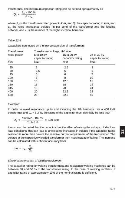
12
577
transformer. The maximum capacitor rating can be defined approximately asSrT · 100 %
Qc < ———————ν2 · ukr
where SrT is the transformer rated power in kVA, and Qc the capacitor rating in kvar, andukr the rated impedance voltage (in per cent) of the transformer and the feedingnetwork, and v is the number of the highest critical harmonic.
Table 12-9
Capacitors connected on the low-voltage side of transformers
Transformer Transformer voltage, HV siderated power 5 to 10 kV 15 to 20 kV 25 to 30 kV
capacitor rating capacitor rating capacitor ratingkVA kvar kvar kvar
25 2 2.5 350 3.5 5 675 5 6 7
100 6 8 10160 10 12.5 15250 15 18 22315 18 20 24400 20 22.5 28630 28 32.5 40
Example:
In order to avoid resonance up to and including the 7th harmonic, for a 400 kVAtransformer and ukr = 6.2 %, the rating of the capacitor must definitely be less than
400 kVA · 100 %Qc < —————————— = 130 kvar
72 · 6.2 %
It must also be noted that the capacitor has the effect of raising the voltage. Under low-load conditions, this can lead to unwelcome increases in voltage if the capacitor ratingselected is more than covers the reactive current requirement of the transformer. Thevoltage at the capacitively loaded transformer then rises instead of falling. The increasecan be calculated with sufficient accuracy from
Qc∆ u ≈ ukr · ——.SrT
Single compensation of welding equipment
The capacitor rating for welding transformers and resistance welding machines can bebetween 30 and 50 % of the transformer rating. In the case of welding rectifiers, acapacitor rating of approximately 10% of the nominal rating is sufficient.

578
Fig. 12-12
Group compensation
Group compensation
The phase-shifting capacitor is connected to the distribution bus feeding, for example,a large number of small motors running continuously or intermittently, Fig. 12-12.
Short-circuit protection should consist of HV fuses, for each capacitor if required.Voltage transformers in V connection are necessary for discharging afterdisconnection.
Centralized compensation can be used for all voltages.
Fig. 12-13
Centralized compensation:
a) Total compensation, b) Compensation with automaticcontrol
The motors and capacitors are switched by separate switches and supervised byseparate protection systems. The capacitors can be switched on and off individually orin groups, as required.
Centralized compensation
In comparatively large installations with many small and medium-size loads (motors,etc.) which are not usually in operation at the same time, the phase-shifting capacitorsare connected centrally to the main busbar. The capacitors are switched either jointlyby hand (Fig. 12-13a) or automatically via regulators responding to time or reactive load(Fig. 12-13b).
Advantages: automatic control allows the capacitor rating to be closely matched to thereactive power required at any time, thus keeping cos ϕ closer to the specified value.
Disadvantage: distributing lines between busbar and points of consumption still carrythe same reactive current.
a) b)

12
579
12.4 Resistor devices
Resistor devices for low and high voltage are used in switchgear installations as
– Damping resistors for high-pass filters, in conjunction with arc suppression coils andfor limiting capacitive and inductive overvoltages,
– Earthing resistors for earthing the neutrals of transformers and generators and alsofor earth fault protection,
– Loading resistors,
– Voltage dividers,
– Discharge resistors for capacitors,
– Transition and series resistors for tap changers,
– Starting and braking resistors and rheostats for electric motors.
The live parts are in the form of wire or cast elements or corrugated sheet-steel lattices.These components are made up into assemblies with ceramic insulators and can takethe form of banks mounted on a frame.
Insulators are used for medium and high voltages.
In a resistor unit, electrical energy is converted into heat which the body of the resistorcan absorb only partly and only for a very short time. It must always be dissipated to theambient air. Resistor units are therefore usually air-cooled. Natural ventilation isgenerally sufficient. Separate ventilation or oil cooling is advisable in special cases.
The resistor elements normally have a tolerance of + 10 %. Smaller tolerances arepossible in special cases.
The rise in temperature, which can be up to about 400 K, increases the resistance. Withcast iron resistors, for example, the resistance increase is 7.5 %/100 K (Table 12-10).When the maximum temperature of about 400 °C is reached, a nominal initial current of600 A has fallen to 460 A.
Resistors are often not designed for a 100 % load factor, but only to operate for a limitedtime. If during this short period the load duration tB < Tϑ, a higher loading is permissible.The maximum load duration tBmax during which the resistor element heats up to thepermitted temperature limit with an overload of Ia = a · Ir, is
a2
tBmax = Tϑ · ln (———).a2 – 1
A sufficiently long interval must then follow to allow complete cooling.
Example:
Earthing resistors in medium and high-voltage installations for impedance earthing ofgenerator and transformer neutrals must limit the earth fault current to values of 0.5 to0.75 I"k3. The resulting values are no danger, particularly with regard to electricalmachines, and voltage rises due to any capacitive effects of network asymmetry areavoided. Also, in branched networks, a defined active current can be produced whichmakes it easier to measure and localize an earth fault. The load factor for theseearthing resistors is governed by the protective devices in question and their speed ofresponse.
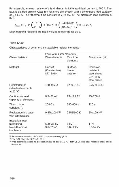
580
Table 12-10
Characteristics of commercially available resistor elements
Form of resistor elementsCharacteristics Wire elements Cast iron Sheet steel grid
elements
Material CuNi44 Surface- Corrosion-(Constantan) treated resistantNiCr8020 cast iron steel sheet
CrNi alloysteel sheet
Resistance of 150–0.5 Ω 02–0.01 Ω 0.75–0.04 Ωindividual elementsat 20 °C
Continuous load 0.5–20 A3) 25–125 A3) 25–250 Acapacity of elements
Therm. time 20-90 s 240-600 s 120 sconstant Tϑ
Resistance increase 0.4%/100 K1) 7.5%/100 K 5%/100 K2)
with temperature
Insulation levelto housing 600 V/1 kV 1 kV 1 kVto earth across 3.6-52 kV 3.6-52 kV 3.6-52 kVinsulators
1) Resistance variation of CuNi44 (constantan) negligible. 2) For CrNi alloy sheet 2 % / 100 K. 3) Wire elements cease to be economical at about 15 A. From 25 A, use cast-metal or steel-sheet
elements.
For example, an earth resistor of this kind must limit the earth fault current to 400 A. Thefault is cleared quickly. Cast iron resistors are chosen with a continuous load capacityof Ir = 60 A. Their thermal time constant is Tϑ = 450 s. The maximum load duration isthus
a2 (400 /60)2
tBmax = Tϑ · ln (———) = 450 s · ln (————————) = 10.25 s.a2 – 1 (400 /60)2 –1
Such earthing resistors are usually sized to operate for 10 s.

12
581
12.5 Rectifiers
Semiconductor rectifiers are used exclusively today for rectifying alternating currents.
Rectifier assemblies are identified according to DIN VDE 0556. The identity codeshows the connection, rated connected voltage, rated DC voltage and rated DC currentof the assembly.
Example: Code letter for connection
Rated connected voltage in V
Rated DC voltage in V
Rated DC current in A
Code letter for assisted cooling(omitted with natural cooling)
F separate ventilationO oil cooling
B 275 / 220 – 10 or: S 400 / 224 – 162 F
If a rectifier assembly consists of several stacks (e.g. 4) a single stack is designated:
1/4 B 275 / 220 – 10
Table 12-11 shows a summary of calculation data for common rectifier circuits.The symbols denote the following:
u2 = Instantaneous value of applied AC voltage
U2 = Root-mean-square value of applied AC voltage
ug = Instantaneous value of rectified voltage
Ug = Arithmetic mean of rectified voltage
Ugo = Open-circuit DC voltage
ig = Instantaneous value of rectified current
Ig = Arithmetic mean of rectified current

582
Table 12-11
Basic calculation data for common rectifier connections
Connection to Alternating current 3-phase AC
Connection Half-wave Centre-tap Bridge Star 3-phase Double-starbridge
Circuit diagram Fig. 12-14 Fig. 12-16 Fig. 12-17 Fig. 12-18 Fig. 12-19 Fig. 12-20
No. of pulses p 1 2 2 3 6 6
Fundamental frequency of super-50 100 100 150 300 300imposed AC voltage (Hz)
Open-circuit DC voltage Ugo/U2 2 2 2 2 3 2 3 2 3 2–— = 0.45 –— = 0.45 –—— = 0.9 –—— = 0.67 –—— = 1.35 –—— = 0.67π π π 2 π π 2 π
Rating of each valve
as regards voltage for U2 U2 U2 U2 U2 U2
as regards current for Ig ¹₂Ig ¹₂Ig ¹₂Ig ¹₃Ig ¹₆Ig
Connected network power 2.69 1.23 1.23 1.23 1.05 1.05P1 / (Ugo · Ig) 1.111) 1.111)
Mean transformer rating 3.09 1.49 1.23 1.37 1.05 1.551.341) 1.111)
Voltage ripple(in % of Ugo) 121.1 48.3 48.3 18.3 4.2 4.2
1) For operation with inductive load (e.g. Iarge smoothing reactor)All other figures apply to purely resistive load.

12
583
Common rectifier connections
1. Half-wave connection, symbol E, see Fig. 12-14
The simplest of all rectifier connections. It consists of a branch which blocks onehalf-wave of the applied AC voltage. The result is a pulsating DC voltage with gapswhile the voltage is negative. This arrangement is normally used only for smallcurrents (often in conjunction with capacitors) and up to very high voltages with asuitable number of plates or stacks connected in series. The rectifier assembly mustblock the full transformer voltage and when capacitors are used, their chargingvoltage as well.
Fig. 12-15
Doubler connection a) Circuit diagram b) Voltage curve
2. Doubler connection, symbol V, see Fig. 12-15
This arrangement is again suitable only for small currents and relatively highvoltages. It always requires two capacitors which are charged in each half-cycle andwhen connected in series, produce at no-load a DC voltage corresponding to twicethe peak voltage of the applied AC voltage. Under load, the DC voltage decreasesaccording to the relationship between capacitance and load current. Each branch ofthe rectifier assembly has to block the sum of transformer voltage and capacitorvoltage.
3. Centre-tap connection, symbol M, see Fig. 12-16
This arrangement requires a transformer which has a centre tap on its secondarywinding. In the blocking direction, each branch carries the full transformer voltage.The connection is economical only for low voltages using the basic unit. For highervoltages requiring semiconductor devices to be connected in series, it is inferior to
Fig. 12-14
Half-wave connectiona) Circuit diagram b) Voltage curve

584
4. Bridge connection, symbol B, see Fig. 12-17.
Provided the voltages involved are not very low, in which case the centre-tapconnection may be preferable, the bridge connection is the most practical andeconomical over a wide range of currents and voltages, and therefore the mostcommonly used of all single-phase arrangements. In the blocking direction, each ofthe 4 branches is subjected to the full transformer voltage.
the following bridge connection because of the special transformer construction forthe same number of plates. It is then appropriate only if suitable transformers arealready available, i.e. when hot cathode or mercury vapour rectifiers are to bereplaced by semiconductor units.
Fig. 12-16
Centre-tap connection a) Circuit diagram b) Voltage curve
Fig. 12-17
Bridge connection a) Circuit diagram b) Voltage curve
Fig. 12-18
Star connection a) Circuit diagram b) Voltage curve
5. Star connection, symbol S, see Fig. 12-18.
This three-phase arrangement requires transformers, or networks in the case ofstraight connection, whose neutral is able to withstand the full direct current. Theconnection’s power rating is unlimited. However, it is practically used only whenmercury vapour rectifiers require replacement. Each branch is subjected to thephase-to-phase voltage. With voltages which exceed the nominal blocking voltage ofone rectifier device, the following three-phase bridge connection will probably bepreferable with the same number of devices. When directly linked to 380 Vthree-phase networks with loadable neutral, the star connection provides a DCvoltage of the order of 220 to 230 V.

12
585
Fig. 12-19
Three-phase bridge connection a) Circuit diagram b) Voltage curve
Fig. 12-20
Double-star connection a) Circuit diagram b) Voltage curve
7. Double-star connection, symbol DS, see Fig. 12-20
This arrangement corresponds to the centre-tap connection of the single-phaseconfigurations. Again, it is used almost exclusively only with low voltages requiringone basic unit, but currents can be high. With higher voltages, it can berecommended only when replacing the glass or iron cells of mercury vapourrectifiers. In the blocking direction, each of the 6 branches carries twice the phasevoltage.
6. Three-phase bridge connection, symbol DB, see Fig. 12-19
This is the most convenient and economical connection for all relatively high powersat voltages exceeding those of the basic star or double-star connections. Here again,each of the 6 branches carries the phase-to-phase voltage in the blocking direction.

586

13
587
13 Conductor Materials and Accessories forSwitchgear Installations
13.1 Busbars, stranded-wire conductors and insulators
13.1.1 Properties of conductor materials
Busbars for switchgear installations are made either of copper (E-Cu) or of aluminium(E-AI). Aluminium alloys with good electrical and mechanical properties are also used.
An advantage of aluminium is that a short-circuit arc gives rise only to non-conducting,dust-like residues of aluminium oxide. No metal is deposited on the neighbouringinsulators or other components of the installation, thus limiting the extent of thedamage. Switchgear installations with aluminium busbars can therefore bereconnected much more quickly after a short-circuit arc.
The values given in Table 13-1 are typical values to be used in calculations concerningthe construction of switchgear installations; the most important physical properties ofcommonly used conductor materials are compared in Table 13-2.
Table 13-1
Typical values for the properties of conductor materials
Symbol Tensile Young’s Yield strength Brinell Conductivitystrength modulus E Rp02 R’p02 hardness κ at 20 °CRm Elasticity HB 10min. modulus min. max. min.N/ mm2 N/ mm2 N/ mm2 N/ mm2 N/ mm2 m/ Ωmm2
CopperE-Cu F 20 200 11 · 104 120 450… 700 57E-Cu F 25 250 11 · 104 200 290 700… 950 56E-Cu F 30 300 11 · 104 250 360 800…1050 56E-Cu F 37 370 11 · 104 330 400 950…1150 55
AluminiumE-AI F 6.5/7 65/70 6.5 · 104 25 180 200… 300 35.4E-AI F 8 80 6.5 · 104 50 100 220… 320 35.2E-AI F 10 100 6.5 · 104 70 120 280… 380 34.8E-AI F 13 130 6.5 · 104 90 160 320… 420 34.5Al F 10 100 ≈ 6.5 · 104 70 280… 300 34
Malleable aluminium alloyE-AI Mg Si 0.5 F 17 170 7 · 104 120 180 450… 650 32E-AI Mg Si 0.5 F 22 220 7 · 104 160 240 650… 900 30
Copper-clad aluminiumCu comprises 15 % 130 8 · 104 100 130 — 42.3
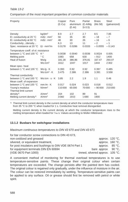
588
Table 13-2
Comparison of the most important properties of common conductor materials
Property Copper Pure Pantal Brass Steel(E-Cu) aluminium (E-AIMg (Ms 58) (galvanized)
(E-AI) Si 0.5)
Density kg/dm3 8.9 2.7 2.7 8.5 7.85El. conductivity at 20 °C m/Ω · mm2 56 35 30 ≈ 18 ≈ 7El. conductivity at 60 °C m/Ω · mm2 48 30 26 ≈ 16 ≈ 6Conductivity.../density... 6.3 13 11 ≈ 2 ≈ 1Spec. resistance at 20 °C Ω · mm2/m 0.0178 0.0286 0.0333 ≈ 0.0555 ≈ 0.143
Temperature coeff. of el. resistancebetween 1 °C and 100 °C K-1 0.0038 0.0040 0.0036 0.0024 0.005Melting point ° C 1083 658 630 ≈ 912 1400Heat of fusion Ws/g 181.28 386.86 376.81 167.47 293.07
Ws /cm3 1612 1047 1017 1444 2 302Mean spec. heatbetween 1 °C and 100 °C Ws /g · K 0.393 0.92 0.92 0.397 0.485
Ws /cm3 · K 3.475 2.386 2.386 3.391 3.558Thermal conductivitybetween 1 °C and 100 °C Ws /cm · s · K 3.85 2.2 1.9 1.1 0.46Mean coeff. of expansionbetween 1 °C and 100 °C mm /m · K 0.017 0.024 0.023 0.018 0.012Young’s modulus N/mm2 110 000 65 000 70 000 ≈ 90 000 210 000Thermal limit currentdensity1) A/mm2 154 102 89 91Melting current density1) A/mm2 3 060 1910 1 690 1900
1) Thermal limit current density is the current density at which the conductor temperature risesfrom 35 °C to 200 °C when loaded for 1 s. Conductive heat removal disregarded.
Melting current density is the current density at which the conductor temperature rises to themelting temperature when loaded for ¹⁄₁₀₀ s. Values according to Müller-Hillebrand.
13.1.2 Busbars for switchgear installations
Maximum continuous temperatures to DIN 43 670 and DIN 43 671
for bar conductor screw connections to DIN 43 673,non-oxidized and greased approx. 120 °C,silvered, or equivalent treatment, approx. 160 °C,for post insulators and bushings to DIN VDE 0674 Part 1 approx. 85 °C,for equipment terminals DIN EN 60694 bare approx 90 °C,(VDE 0670 Part 1000) tinned, silvered approx. 105 °C.
A convenient method of monitoring for thermal overload temperatures is to usetemperature-sensitive paints. These change their original colour when certaintemperatures are exceeded. The change persists after the painted item has cooled.The original colour is regained only gradually, under the influence of moisture in the air.The colour can be restored immediately by wetting. Temperature-sensitive paints canbe applied to any surface. Oil or grease should first be removed with petrol or whitespirit.

13
589
Influence of bar temperature on strength of conductor material
The strength of the conductor material decreases with rising temperature, and muchmore rapidly with aluminium than with copper. The values in Table 13-3 are valid foraluminium. For temperatures above 160 °C, they also depend on the duration ofheating.
Table 13-3
Influence of temperature on the strength of aluminium
Temperature 20 100 160 250 °C
Tensile strength σB 90…130 90…120 80…110 70…30 N/mm2
Yield point Rp0.2 80…120 80…110 70…100 60…30 N/mm2
Elongation at fracture 10…5 10…5 11…7 to 60 %
Under short-circuit conditions, therefore, conductor temperatures of 200 °C foraluminium and for copper must not be exceeded, see VDE 0103.
If items of equipment are influenced only very slightly, or not at all, by the thermalbehaviour of the busbars, the maximum permissible conductor temperature isgoverned only by the long-term thermal strength of the conductors and their insulation.
This is the case, for example, with busbars which owing to sufficiently long connectionsare not thermally coupled to their associated equipment.
Profile selection and arrangement for alternating current
The cross-sectional shape of busbar conductors has a considerable influence not onlyon their bending strength, but also on their electrical load capacity.
With direct current, there is no skin effect, so in this case the shape of the conductor isimportant only with regard to the heat-emitting surface area. For direct current,therefore, it is preferable to use flat bars or continuously cast conductors of large crosssection.
With alternating current, on the other hand, skin effect and other factors cause anincrease in the conductor resistance, and this must be kept small by selecting anappropriate section profile. The effect the shape and arrangement of componentconductors of the same total cross-section area can have on the current-carryingcapacity of busbars for AC is illustrated in Fig. 13-1.
If the current permits, one or two flat conductors per phase are provided, thussimplifying installation. Two conductors is the most favorable number from thestandpoint of losses, and is therefore to be preferred.
For higher currents, four flat conductors have proved to be an effective arrangement.The distance between the second and third conductor has to be increased in order toachieve a better current distribution. Increasing the distance from 10 to 30 mmproduces no significant improvement. It has been shown that with a distance of 70 mm,the relative currents in the individual conductors differ by only + 7%.

590
The loading on the four conductors is then:
Conductor 1 2 3 4Current carried as % of total current 26.7 23.3 23.3 26.7
If four flat conductors per phase are not sufficient, then channel sections areconsidered. These have favorable skin effect properties. If even more flat conductorswere to be used, the result would be a comparatively large cross-section which, inaddition, is very uneconomical. For example, an arrangement with seven conductorswould give the following current distribution among the conductors:
Conductor 1 2 3 4 5 6 7Relative current % 25.6 14.2 7.5 5.4 7.5 14.2 25.6
For high currents in low-voltage installations, when using flat conductors, the simplestsolution is to split up large composite conductors by dividing the three phases amongsmaller cross sections, Fig. 13-2. These then have a significantly lower eddy-currentfactor and also a smaller inductive voltage drop.
Fig. 13-1
Current-carrying capacity per cent of some busbar conductor arrangements of thesame total cross-section area
Fig. 13-2
Arrangement of a three-phase bus with four parallel conductors per phase: a) Usual arrangement with the three phases L1, L2, L3 next to each otherb) Conductors in split phase arrangement L1, L2, L3, L1, L2, L3 …
Continuous current-carrying capacity
The Tables 13-4 to 13-12 below give values for the continuous current-carrying capacityof different cross-sections of copper (see DIN 43671) and aluminium (see DIN 43670).

13
591
For indoor installations1), the tables are based on the following assumptions:
1. ambient air still,
2. bare conductors partly oxidized, giving a radiation coefficient of 0.40 (Cu) and 0.35 (Al), or
3. conductors painted (only the outside surfaces in the case of composite busbars),giving a radiation coefficient of approx. 0.90.
For outdoor installations, the tables are based on the following assumptions:
1. slight air movement, e.g. due to ground thermals, of 0.6 m/s,
2. bare conductors normally oxidized, giving a radiation coefficient of 0.60 (Cu) and0.50 (Al), possible solar irradiation 0.45 (Cu) and 0.35 (Al) kW/m2, or
3. conductors painted, giving a radiation coefficient of approx. 0.90 and solarirradiation of 0.7 kW/m2.The values for outdoor installations thus correspond to central European conditions.
1) For open-type indoor installations, the values stated in the tables can be multiplied by between 1.05and 1.1 since it is found that slight air movements independent of the busbars occur in such cases.

592 Continuous current-carrying capacity of copper conductors (DIN 43 671)
Table 13-4
Copper conductors of rectangular cross-section in indoor installations. Ambient temperature 35 °C. Conductor temperature 65 °C. Conductorwidth vertical: clearance between conductors equal to conductor thickness; with alternating current, clearance between phases > 0.8 × phasecentre-line distance.
Width Cross- Weight1) Material3) Continuous current in A Continuous current in A× section AC up to 60 Hz DC and AC 16²⁄₃ Hzthickness painted bare painted bare
no. of conductors no. of conductors no. of conductors no. of conductors1 2 3 4 1 2 3 4 1 2 3 4 1 2 3 4
mm mm2 kg/m
12 × 15 59.5 0.529 E-Cu F 37 203 345 411 177 312 398 203 345 411 177 312 39812 × 10 119.5 1.063 E-Cu F 37 326 605 879 285 553 811 326 605 879 285 553 811
20 × 15 99.1 0.882 E Cu F 37 319 560 728 274 500 690 320 562 729 274 502 68720 × 10 199 1.77 E-Cu F 30 497 924 1 320 427 825 1 180 499 932 1 300 428 832 1 210
30 × 15 149 1.33 E-Cu F 37 447 760 944 379 672 896 448 766 950 380 676 89730 × 10 299 2.66 E-Cu F 30 676 1 200 1 670 573 1 060 1 480 683 1 230 1 630 579 1 080 1 520
40 × 15 199 1.77 E-Cu F 37 573 952 1 140 482 836 1 090 576 966 1 160 484 848 1 10040 × 10 399 3 55 E-Cu F 30 850 1 470 2 000 2 580 715 1 290 1 770 2 280 865 1 530 2 000 728 1 350 1 880
1) Calculated for a density of 8.9 kg/dm3.2) Minimum clearance given in mm.3) Material: E-Cu or other material to DIN 40500 Part 3, preferred semi-finished material. Flat bars with rounded edges to DIN 46433 Selection Part 3.
Continued on next page

13
593
Table 13-4 (continued)
Copper conductors of rectangular cross-section in indoor installations. Ambient temperature 35 °C. Conductor temperature 65 °C. Conductorwidth vertical: clearance between conductors equal to conductor thickness; with alternating current, clearance between phases > 0.8 × phasecentre-line distance.
Width Cross- Weight1) Material3) Continuous current in A Continuous current in A× section AC up to 60 Hz DC and AC 16²⁄₃ Hzthickness painted bare painted bare
no. of conductors no. of conductors no. of conductors no. of conductors1 2 3 4 1 2 3 4 1 2 3 4 1 2 3 4
mm mm2 kg/m
50 × 15 249 2.22 E-Cu F 37 679 1 140 1 330 2 010 583 994 1 240 1 920 703 1 170 1370 1 588 1 020 1 30050 × 10 499 4.44 E-Cu F 30 1 020 1 720 2 320 2 950 852 1510 2 040 2 600 1 050 1 830 2 360 1 875 1 610 2 220
60 × 15 299 2.66 E-Cu F 30 826 1 330 1 510 2 310 688 1 150 1 440 2 210 836 1 370 1 580 2 060 1 696 1 190 1 500 1 97060 × 10 599 5.33 E-Cu F 30 1 180 1 960 2 610 3 290 985 1 720 2 300 2 900 1 230 2 130 2 720 3 580 1 020 1 870 2 570 3 390
80 × 15 399 3.55 E-Cu F 30 1 070 1 680 1 830 2 830 885 1 450 1 750 2 720 1 090 1 770 1 990 2 570 1 902 1 530 1 890 2 46080 × 10 799 7.11 E-Cu F 30 1 500 2 410 3 170 3 930 1 240 2 110 2 790 3 450 1 590 2 730 3 420 4 490 1 310 2 380 3 240 4 280
100 × 15 499 4.44 E-Cu F 30 1 300 2 010 2 150 3 300 1 080 1 730 2 050 3 190 1 340 2 160 2 380 3 080 1 110 1 810 2 270 2 960 100 × 10 988 8.89 E-Cu F 30 1 810 2 850 3 720 4 530 1 490 2 480 3 260 3 980 1 940 3 310 4100 5 310 1 600 2 890 3 900 5 150
120 × 10 1 200 10.7 E-Cu F 30 2 110 3 280 4 270 5 130 1 740 2 860 3 740 4 500 2 300 3 900 4 780 6 260 1 890 3 390 4 560 6 010
160 × 10 1 600 14.2 E-Cu F 30 2 700 4 130 5 360 6 320 2 220 3 590 4 680 5 530 3 010 5 060 6 130 8 010 2 470 4 400 5 860 7 710200 × 10 2 000 17.8 E-Cu F 30 3 290 4 970 6 430 7 490 2 690 4 310 5 610 6 540 3 720 6 220 7 460 9 730 3 040 5 390 7 150 9 390
1) Calculated for a density of 8.9 kg/dm3.2) Minimum clearance given in mm.3) Material: E-Cu or other material to DIN 40500 Part 3 preferred semi-finished material. Flat bars with rounded edges to DIN 46433 Selection Part 3.

594
Table 13-5
Copper conductors of annular cross-section, ambient temperature 35 °C, conductortemperature 65 °C, with alternating current, phase centre-line distance 2.5 × outsidediameter
Outside Wall- Cross- Weight1) Material2) Continuous in Adiameter thick- section DC and AC
ness up to 60 HzD a indoor outdoormm mm mm2 kg/m painted bare painted bare
20 2 113 1.01 E-Cu F 37 384 329 460 4493 160 1.43 E-Cu F 37 457 392 548 5354 201 1.79 E-Cu F 30 512 438 613 5995 236 2.10 E-Cu F 30 554 475 664 6486 264 2.35 E-Cu F 25 591 506 708 691
32 2 188 1.68 E-Cu F 37 602 508 679 6603 273 2.44 E-Cu F 37 725 611 818 7944 352 3.14 E-Cu F 30 821 693 927 9005 424 3.78 E-Cu F 30 900 760 1 020 9876 490 4.37 E-Cu F 25 973 821 1 100 1 070
40 2 239 2.13 E-Cu F 37 744 624 816 7903 349 3.11 E-CU F 37 899 753 986 9554 452 4.04 E-Cu F 30 1 020 857 1 120 1 0905 550 4.90 E-Cu F 30 1 130 944 1 240 1 2006 641 5.72 E-Cu F 25 1 220 1 020 1 340 1 300
50 3 443 3.95 E-Cu F 37 1 120 928 1 190 1 1504 578 5.16 E-Cu F 30 1 270 1 060 1 360 1 3105 707 6.31 E-Cu F 30 1 410 1 170 1 500 1 4506 829 7.40 E-Cu F 25 1 530 1 270 1 630 1 5708 1 060 9.42 E-Cu F 25 1 700 1 420 1 820 1 750
63 3 565 5.04 E-Cu F 30 1 390 1 150 1 440 1 3904 741 6.61 E-Cu F 30 1 590 1 320 1 650 1 5905 911 8.13 E-Cu F 30 1 760 1 460 1 820 1 7506 1 070 9.58 E-Cu F 25 1 920 1 590 1 990 1 9108 1 380 12.3 E-Cu F 25 2 150 1 780 2 230 2 140
80 3 726 6.47 E-Cu F 30 1 750 1 440 1 760 1 6904 955 8.52 E-Cu F 30 2 010 1 650 2 020 1 9305 1 180 10.5 E-Cu F 30 2 230 1 820 2 230 2 1406 1 400 12.4 E-Cu F 25 2 430 1 990 2 440 2 3408 1 810 16.1 E-Cu F 25 2 730 2 240 2 740 2 630
100 3 914 8.15 E-Cu F 30 2 170 1 770 2 120 2 0204 1 210 10.8 E-Cu F 30 2 490 2 030 2 430 2 3205 1 490 13.3 E-Cu F 30 2 760 2 250 2 700 2 5806 1 770 15.8 E-Cu F 25 3 020 2 460 2 950 2 8208 2 310 20.6 E-Cu F 25 3 410 2 780 3 330 3 180
1) Calculated for a density of 8.9 kg/dm3. Preferred outside diameters in heavy type. 2) Material: E-Cu or other material to DIN 40500 Part 2; preferably semi-finished material to be used:
tube to DIN 1754.

13
595
Table 13-6
Copper conductors of round cross-section (round copper bar), ambient temperature 35°C, conductor temperature 65 °C; with alternating current, phase centre-line distance 2 × diameter.
Diameter Cross- Weight1) Material2) Continuous current in Asection DC and AC
D a up to 60 Hzmm mm2 kg/m painted bare
5 19.6 0.175 E-Cu F 37 95 858 50.3 0.447 E-Cu F 37 179 159
10 78.5 0.699 E-Cu F 37 243 21316 210 1.79 E-Cu F 30 464 40120 314 2.80 E-Cu F 30 629 53932 804 7.16 E-Cu F 30 1 160 97650 1960 17.50 E-Cu F 30 1 930 1 610
1) Calculated for a density of 8.9 kg/dm3. 2) Material: E-Cu or other material to DIN 40500 Part 3, preferably semi-finished product to be used:
round bars to DIN 1756.

596 Continuous current-carrying capacity of aluminium conductors (DIN 43670)
Table 13-7
Aluminium conductors of rectangular cross-section in indoor installations. Ambient temperature 35 °C. Conductor temperature 65 °C.Conductor width vertical: clearance between conductors equal to conductor thickness; with alternating current, clearance between phases >0.8 × phase centre-line distance.
Width Cross- Weight1) Material3) Continuous current in A Continuous current in A× section AC up to 60 Hz DC and AC 16²⁄₃ Hzthickness painted bare painted bare
no. of conductors no. of conductors no. of conductors no. of conductors1 2 3 4 1 2 3 4 1 2 3 4 1 2 3 4
mm mm2 kg/m
12 × 15 59.5 0.160 E-AI F 10 160 292 398 139 263 375 160 292 398 139 263 37512 × 10 119.5 0.322 E-AI F 10 257 490 720 224 440 652 257 490 720 224 440 652
20 × 15 99.1 0.268 E-AI F 10 254 446 570 214 392 537 254 446 576 214 392 53920 × 10 199 0.538 E-AI F 10 393 730 1 060 331 643 942 393 733 1 020 331 646 943
30 × 15 149 0.403 E-AI F 10 356 606 739 295 526 699 356 608 749 296 528 70330 × 10 299 0.808 E-AI F 10 536 956 1340 445 832 1 200 538 964 1 280 447 839 1 180
40 × 15 199 0.538 E-AI F 10 456 762 898 376 658 851 457 766 915 376 662 86240 × 10 399 1.08 E-AI F 10 677 1 180 1 650 2 190 557 1 030 1 460 1 900 682 1200 1 570 561 1 040 1 460
50 × 15 249 0.673 E-AI F 10 556 916 1 050 1 580 455 786 995 1 520 558 924 1 080 456 794 1 02050 × 10 499 1.35 E-AI F 10 815 1 400 1 940 2 540 667 1 210 1 710 2 210 824 1 140 1 850 674 1 250 1 730
60 × 15 299 0.808 E-AI F 10 655 1 070 1 190 1 820 533 910 1 130 1 750 658 1 080 1 240 1 610 536 924 1 170 1 53060 × 10 599 1.62 E-AI F 10 951 1 610 2 200 2 870 774 1 390 1 940 2 480 966 1 680 2 130 2 810 787 1 450 2 000 2 650
Continued on next page

13
597
Table 13-7 (continued)
Width Cross- Weight1) Material3) Continuous current in A Continuous current in A× section AC up to 60 Hz DC and AC 16²⁄₃ Hzthickness painted bare painted bare
no. of conductors no. of conductors no. of conductors no. of conductors1 2 3 4 1 2 3 4 1 2 3 4 1 2 3 4
mm mm2 kg/m
180 × 15 399 1.08 E-AI F 10 1 851 1 360 1 460 2 250 1 688 1 150 1 400 2 180 1 858 1 390 1 550 2 010 1 694 1 180 1 470 1 920180 × 10 799 2.16 E-AI F 10 1 220 2 000 2 660 3 460 1 983 1 720 2 380 2 990 1 250 2 150 2 670 3 520 1 010 1 840 2 520 3 340
100 × 15 499 1.35 E-AI F 6.5 1 050 1 650 1 730 2 660 1 846 1 390 1 660 2 580 1 060 1 710 1 870 2 420 1 858 1 450 1 780 2 320100 × 10 999 2.70 E-AI F 6.5 1 480 2 390 3 110 4 020 1 190 2 050 2 790 3 470 1 540 2 630 3 230 4 250 1 240 2 250 3 060 4 050100 × 15 1 500 4.04 E-AI F 6.5 1 800 2 910 3 730 4 490 1 450 2 500 3 220 3 380 1 930 3 380 4 330 5 710 1 560 2 900 4 070 5 400
120 × 10 1 200 3.24 E-AI F 6.5 1 730 2 750 3 540 4 560 1 390 2 360 3 200 3 930 1 830 3 090 3 770 4 940 1 460 2 650 3 580 4 730120 × 15 1 800 4.86 E-AI F 6 5 2 090 3 320 4 240 5 040 1 680 2 850 3 650 4 350 2 280 3 950 5 020 6 610 1 830 3 390 4 740 6 280
160 × 10 1 600 4.32 E-AI F 6.5 2 220 3 470 4 390 5 610 1 780 2 960 4 000 4 820 2 380 4 010 4 820 6 300 1 900 3 420 4 590 6 060160 × 15 2 400 6.47 E-Al F 6.5 2 670 4 140 5 230 6 120 2 130 3 540 4 510 5 270 2 960 5 090 6 370 8 380 2 370 4 360 6 040 8 000
200 × 10 2 000 5.40 E-Al F 6.5 2 710 4 180 5 230 6 660 2 160 3 560 4 790 5 710 2 960 4 940 5 880 7 680 2 350 4 210 5 620 7 400200 × 15 3 000 8.09 E-AI F 6.5 3 230 4 950 6 240 7 190 2 580 4 230 5 370 6 190 3 660 6 250 7 740 10 160 2 920 5 350 7 370 9 750
1) Calculated for a density of 2.7 kg/dm3. 2) Minimum clearance given in mm.3) Material: E-Al or other material to DIN 40501 Part 3, preferred semi-finished material. Flat bars with rounded edges to DIN 46 433 Selection Part 3.

598
Table 13-8
Aluminium conductors of U-section in indoor installations, ambient temperature 35 °C,conductor temperature 65 °C.
When facing [ ], gap vertical; with alternatingcurrent, phase centre-line distance 2h
Material: E-AI or other material to DIN 40501Part 3; semi-finished product to be used;channel sections to DIN 46424.
Dimensions Cross- Weight1) Material Continuous current in Asection DC and AC
up to 60 Hzpainted bare
h b s d [ [] [ [] [ [] [ []mm mm mm mm mm2 mm2 kg/m kg /m
160 30 14 25 1 448 1 896 1.22 2.44 E-AI F 6.5 1 880 1 800 1 685 1 370180 37.5 16 25 1 858 1 720 2.32 4.64 E-AI F 8 1 460 2 540 1 140 2 000100 37.5 18 25 1 270 2 540 3.47 6.94 E-AI F 8 2 000 3 450 1 550 2 700120 45 10 30 1 900 3 800 5.17 10.3 E-AI F 8 2 720 4 700 2 100 3 750140 52.5 11 35 2 450 4 900 6.66 13.3 E-AI F 8 3 350 5 800 2 600 4 600160 60 12 40 3 070 6 140 8.34 16.7 E-AI F 8 4 000 7 000 3 100 5 400180 67.5 13 45 3 760 7 520 10.2 20.4 E-AI F 8 4 750 8 200 3 800 6 400200 75 14 50 4 510 9 020 12.2 24.4 E-AI F 8 5 500 9 500 4 300 7 400
1) Calculated for a density of 2.7 kg/dm3.
Table 13-9
Aluminium conductors of annular cross-section, ambienttemperature 35 °C, conductor temperature 65 °C; withalternating current, phase centre-line distance 2.0 ×outside diameter.
Outside Wall- Cross- Weight1) Material2) Continuous Continuousdiameter thick- section current in A current in A
ness DC and AC up to 60 HzD a indoor outdoormm mm mm2 kg/m painted bare painted bare
20 2 113 0.305 E-AI F 10 305 257 365 3543 160 0.433 E-AI F 10 363 305 435 4214 201 0.544 E-AI F 10 407 342 487 4725 236 0.636 E-AI F 10 440 370 527 5116 264 0.713 E-AI F 10 465 392 558 540
1) Calculated for a density of 2.7 kg/dm3. Preferred outside diameters in heavy type.2) Material: E-AI or other material to DIN 40501 Part 2; preferably semi-finished product to be used.
Tube to DIN 1795, DIN 9107.Continued on next page

13
599
Table 13-9 (continued)
Outside Wall- Cross- Weight1) Material2) Continuous Continuousdiameter thick- section current in A current in A
ness DC and AC up to 60 HzD a indoor outdoormm mm mm2 kg/m painted bare painted bare
32 2 188 0.509 E-AI F 10 478 395 539 5193 273 0.739 E-AI F 10 575 476 649 6244 352 0.950 E-AI F 10 653 539 737 7085 424 1.15 E-AI F 10 716 592 808 7776 490 1.32 E-AI F 10 769 636 868 835
40 2 239 0.645 E-AI F 10 591 485 648 6213 349 0.942 E-AI F 10 714 595 783 7504 452 1.22 E-AI F 10 813 667 892 8545 550 1.48 E-AI F 10 896 734 982 9416 641 1.73 E-AI F 10 966 792 1 060 1020
50 4 578 1.56 E-AI F 10 1 010 822 1 080 10305 707 1.91 E-AI F 10 1 120 909 1 190 1 1406 829 2.24 E-AI F 10 1 210 983 1 290 1 2308 1 060 2.85 E-AI F 17 1 370 1 110 1 460 1390
10 1 260 3.39 E-AI F 17 1 490 1 210 1 580 1 510
63 4 741 2.00 E-AI F 10 1 270 1 020 1 310 1 2405 911 2.46 E-AI F 10 1 400 1 130 1 450 1 3806 1 070 2.89 E-AI F 10 1 520 1 230 1 570 1 4908 1 380 3.73 E-AI F 17 1 730 1 390 1 790 1 700
80 4 955 2.58 E-AI F 10 1 600 1 280 1 600 1 5105 1 180 3.18 E-AI F 10 1 770 1 420 1 780 1 6806 1 400 3.77 E-AI F 10 1 920 1 540 1 930 1 8208 1 810 4.89 E-AI F 17 2 200 1 760 2 200 2 080
10 2 200 5.94 E-AI F 17 2 410 1 920 2 420 2 280
100 4 1 210 3.26 E-AI F 10 1 980 1 570 1 930 1 8205 1 490 4.03 E-AI F 10 2 200 1 750 2 150 2 0206 1 770 4.78 E-AI F 10 2 390 1 900 2 340 2 2008 2 310 6.24 E-AI F 17 2 740 2 170 2 670 2 510
120 4 1 460 3.94 E-AI F 10 2 360 1 860 2 250 2 1005 1 810 4.88 E-AI F 10 2 620 2 070 2 500 2 3406 2 150 5.80 E-AI F 10 2 860 2 250 2 730 2 5508 2 820 7.60 E-AI F 17 3 270 2 580 3 120 2 920
10 3 460 9.33 E-AI F 17 3 590 2 830 3 420 3 200
160 4 1 960 5.29 E-AI F 10 3 110 2 430 2 910 2 7105 2 440 6.57 E-AI F 10 3 460 2 710 3 240 3 0106 2 900 7.84 E-AI F 10 3 780 2 950 3 530 3 2908 3 820 10.3 E-AI F 17 4 340 3 390 4 060 3 780
10 4 710 12.7 E-AI F 17 4 760 3 720 4 460 4 140
Continued on next page
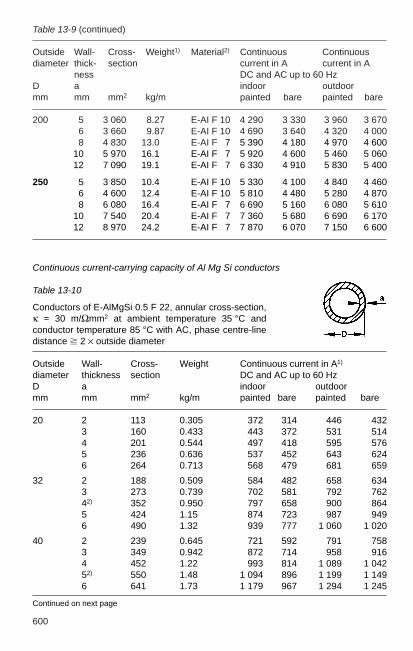
600
Table 13-9 (continued)
Outside Wall- Cross- Weight1) Material2) Continuous Continuousdiameter thick- section current in A current in A
ness DC and AC up to 60 HzD a indoor outdoormm mm mm2 kg/m painted bare painted bare
200 5 3 060 8.27 E-AI F 10 4 290 3 330 3 960 3 6706 3 660 9.87 E-AI F 10 4 690 3 640 4 320 4 0008 4 830 13.0 E-AI F 17 5 390 4 180 4 970 4 600
10 5 970 16.1 E-AI F 17 5 920 4 600 5 460 5 06012 7 090 19.1 E-AI F 17 6 330 4 910 5 830 5 400
250 5 3 850 10.4 E-AI F 10 5 330 4 100 4 840 4 4606 4 600 12.4 E-AI F 10 5 810 4 480 5 280 4 8708 6 080 16.4 E-AI F 17 6 690 5 160 6 080 5 610
10 7 540 20.4 E-AI F 17 7 360 5 680 6 690 6 17012 8 970 24.2 E-AI F 17 7 870 6 070 7 150 6 600
Continuous current-carrying capacity of Al Mg Si conductors
Table 13-10
Conductors of E-AlMgSi 0.5 F 22, annular cross-section,κ = 30 m/Ωmm2 at ambient temperature 35 °C andconductor temperature 85 °C with AC, phase centre-linedistance 2 × outside diameter
Outside Wall- Cross- Weight Continuous current in A1)
diameter thickness section DC and AC up to 60 HzD a indoor outdoormm mm mm2 kg/m painted bare painted bare
20 2 113 0.305 372 314 446 4323 160 0.433 443 372 531 5144 201 0.544 497 418 595 5765 236 0.636 537 452 643 6246 264 0.713 568 479 681 659
32 2 188 0.509 584 482 658 6343 273 0.739 702 581 792 76242) 352 0.950 797 658 900 8645 424 1.15 874 723 987 9496 490 1.32 939 777 1 060 1 020
40 2 239 0.645 721 592 791 7583 349 0.942 872 714 958 9164 452 1.22 993 814 1 089 1 04252) 550 1.48 1 094 896 1 199 1 1496 641 1.73 1 179 967 1 294 1 245
Continued on next page
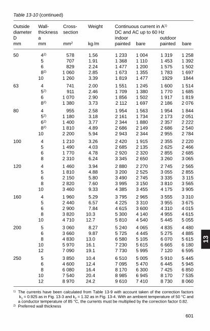
13
601
Table 13-10 (continued)
Outside Wall- Cross- Weight Continuous current in A1)
diameter thickness section DC and AC up to 60 HzD a indoor outdoormm mm mm2 kg /m painted bare painted bare
50 142) 578 1.56 1 233 1 004 1 319 1 25815 707 1.91 1 368 1 110 1 453 1 39216 829 2.24 1 477 1 200 1 575 1 502182) 1 060 2.85 1 673 1 355 1 783 1 69710 1 260 3.39 1 819 1 477 1929 1844
63 14 741 2.00 1 551 1 245 1 600 1 514152) 911 2.46 1 709 1 380 1 770 1 68516 1 070 2.90 1 856 1 502 1 917 1 819182) 1 380 3.73 2 112 1 697 2 186 2 076
80 14 955 2.58 1 954 1 563 1 954 1 844152) 1 180 3.18 2 161 1 734 2 173 2 051162) 1 400 3.77 2 344 1 880 2 357 2 222182) 1 810 4.89 2 686 2 149 2 686 2 54010 2 200 5.94 2 943 2 344 2 955 2 784
100 14 1 210 3.26 2 420 1 915 2 355 2 22015 1 490 4.03 2 685 2 135 2 625 2 46616 1 770 4.78 2 920 2 320 2 855 2 68518 2 310 6.24 3 345 2 650 3 260 3 065
120 14 1 460 3.94 2 880 2 270 2 745 2 56515 1 810 4.88 3 200 2 525 3 055 2 85516 2 150 5.80 3 490 2 745 3 335 3 11518 2 820 7.60 3 995 3 150 3 810 3 56510 3 460 9.33 4 385 3 455 4 175 3 905
160 14 1 960 5.29 3 795 2 965 3 555 3 31015 2 440 6.57 4 225 3 310 3 955 3 67516 2 900 7.84 4 615 3 600 4 310 4 01518 3 820 10.3 5 300 4 140 4 955 4 61510 4 710 12.7 5 810 4 540 5 445 5 055
200 15 3 060 8.27 5 240 4 065 4 835 4 48016 3 660 9.87 5 725 4 445 5 275 4 88518 4 830 13.0 6 580 5 105 6 070 5 61510 5 970 16.1 7 230 5 615 6 665 6 18012 7 090 19.1 7 730 5 995 7 120 6 595
250 15 3 850 10.4 6 510 5 005 5 910 5 44516 4 600 12.4 7 095 5 470 6 445 5 94518 6 080 16.4 8 170 6 300 7 425 6 85010 7 540 20.4 8 985 6 945 8 170 7 53512 8 970 24.2 9 610 7 410 8 730 8 060
1) The currents have been calculated from Table 13-9 with account taken of the correction factorsk1 = 0.925 as in Fig. 13-3 and k2 = 1.32 as in Fig. 13-4. With an ambient temperature of 50 °C anda conductor temperature of 85 °C, the currents must be multiplied by the correction factor 0.82.
2) Preferred wall thickness

602 Continuous current-carrying capacity of copper-clad aluminium conductors (DIN 43 670, Part 2)
Table 13-11
Copper-clad aluminium conductors of rectangular cross-section in indoor installations, ambient temperature 35 °C, conductor temperature65 °C. Conductor width vertical: clearance between conductors equal to conductor thickness; with alternating current, clearance betweenphases > 0.8 × phase centre-line distance.
Width Cross- Weight1) Continuous current in A Continuous current in A× section AC up to 60 Hz DC and AC 16²⁄₃ Hzthickness painted bare painted bare
no. of conductors no. of conductors no. of conductors no. of conductors1 2 3 4 1 2 3 4 1 2 3 4 1 2 3 4
mm mm2 kg/m
12 × 15 59.8 0.217 177 324 440 154 292 416 177 324 442 154 292 41612 × 10 120 0.434 284 542 796 248 488 722 285 544 778 248 488 722
20 × 15 98.7 0.358 265 464 594 225 415 562 265 464 600 225 415 56520 × 10 192 0.698 408 760 1 100 350 680 985 408 763 1 060 350 632 985
30 × 15 148 0.538 370 630 772 313 555 733 370 632 780 313 556 73630 × 10 292 1.06 555 993 1 390 472 870 1 260 558 1 000 1 330 475 876 1 240
40 × 15 198 0.719 474 794 937 400 700 895 475 798 953 400 702 90540 × 10 392 1.42 705 1 230 1 720 2 280 595 1 090 1 540 2 000 710 1 250 1 640 600 1 100 1540
Material: E-AI to DIN 40 501 Parts 2 and 3 and E-Cu to DIN 40 500 Parts 2 and 3, copper cladding comprises 15 % of cross-section area.1) Calculated for a density of 3.63 kg/dm3
2) Minimum clearance given in mm.
(continued)

13
603
mm mm2 kg/m
150 × 15 248 0.901 577 953 1 100 1 650 485 830 1 040 1 580 580 962 1 130 485 840 1 070150 × 10 492 1.79 850 1 460 2 020 2 650 705 1 280 1 890 2 340 860 1 500 1 930 713 1 320 1 810
160 × 15 298 1.08 680 1 120 1 250 1 900 566 965 1 190 1 840 685 1 130 1 300 1 690 570 980 1 230 1 620160 × 10 592 2.15 990 1 680 2 290 2 990 820 1 470 2 030 2 590 1 010 1 750 2 220 2 930 836 1 530 2 100 2 770
180 × 15 398 1.45 890 1 420 1 540 2 340 733 1 230 1 480 2 260 900 1 450 1 630 2 110 740 1 260 1 550 2 020180 × 10 792 2.88 1 270 2 070 2 780 3 600 1 030 1 820 2 500 3150 1 310 2 240 2 800 3 670 1 070 1 950 2 650 3 500
100 × 10 992 3.60 1 540 2 500 3 230 4 180 1 270 2 170 2 940 3 670 1 600 2 740 3 360 4 420 1 320 2 390 3 200 4 200120 × 10 1 192 4.32 1 870 2 850 3 640 4 540 1 540 2 480 3 250 3 980 1 980 3 320 4 330 5 620 1 630 2 880 4 130 5 360
Material: E-AI to DIN 40 501 Parts 2 and 3 and E-Cu to DIN 40 500 Parts 2 and 3, copper cladding comprises 15 % of cross-section area.1) Calculated for a density of 3.63 kg/dm3
2) Minimum clearance given in mm
Table 13-11 (continued)
Copper-clad aluminium conductors of rectangular cross-section in indoor installations. Ambient temperature 35 °C. Conductor temperature 65 °C. Conductor width vertical: clearance between conductors equal to conductor thickness; with alternating current, clearance betweenphases > 0.8 × phase centre-line distance.
Width Cross- Weight1) Continuous current in A Continuous current in A× section AC up to 60 Hz DC and AC 16²⁄₃ Hzthickness painted bare painted bare
no. of conductors no. of conductors no. of conductors no. of conductors1 2 3 4 1 2 3 4 1 2 3 4 1 2 3 4
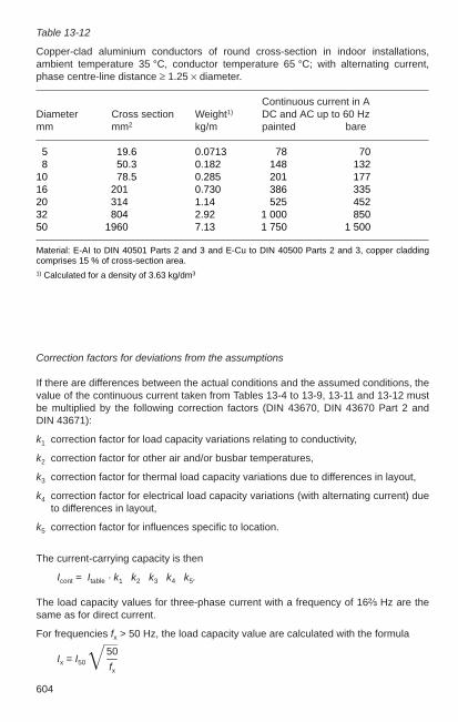
604
Correction factors for deviations from the assumptions
If there are differences between the actual conditions and the assumed conditions, thevalue of the continuous current taken from Tables 13-4 to 13-9, 13-11 and 13-12 mustbe multiplied by the following correction factors (DIN 43670, DIN 43670 Part 2 and DIN 43671):
k1 correction factor for load capacity variations relating to conductivity,
k2 correction factor for other air and/or busbar temperatures,
k3 correction factor for thermal load capacity variations due to differences in layout,
k4 correction factor for electrical load capacity variations (with alternating current) dueto differences in layout,
k5 correction factor for influences specific to location.
The current-carrying capacity is then
Icont = Itable · k1 · k2 · k3 · k4 · k5.
The load capacity values for three-phase current with a frequency of 16²⁄₃ Hz are thesame as for direct current.
For frequencies fx > 50 Hz, the load capacity value are calculated with the formula
50Ix = I50 —
fx
Table 13-12
Copper-clad aluminium conductors of round cross-section in indoor installations,ambient temperature 35 °C, conductor temperature 65 °C; with alternating current,phase centre-line distance ≥ 1.25 × diameter.
Continuous current in ADiameter Cross section Weight1) DC and AC up to 60 Hzmm mm2 kg/m painted bare
15 19.6 0.0713 78 7018 50.3 0.182 148 13210 78.5 0.285 201 17716 201 0.730 386 33520 314 1.14 525 45232 804 2.92 1 000 85050 1960 7.13 1 750 1 500
Material: E-AI to DIN 40501 Parts 2 and 3 and E-Cu to DIN 40500 Parts 2 and 3, copper claddingcomprises 15 % of cross-section area.1) Calculated for a density of 3.63 kg/dm3
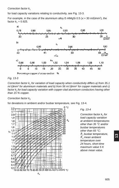
13
605
Correction factor k2
for deviations in ambient and/or busbar temperature, see Fig. 13-4.
Correction factor k1
for load capacity variations relating to conductivity, see Fig. 13-3.
For example, in the case of the aluminium alloy E-AlMgSi 0.5 (κ = 30 m/Ωmm2), thefactor k1 = 0.925.
Fig. 13-4
Correction factor k2 forload capacity variationat ambient temperaturesother than 35 °C and/orbusbar temperaturesother than 65 °C; ϑs busbar temperature, ϑu mean ambienttemperature over 24 hours, short-timemaximum value 5 Kabove mean value.
Fig. 13-3
Correction factor k1 for variation of load capacity when conductivity differs a) from 35.1m/ Ωmm2 for aluminium materials and b) from 56 m/ Ωmm2 for copper materials and c)factor k1 for load capacity variation with copper-clad aluminium conductors having otherthan 15 % copper.
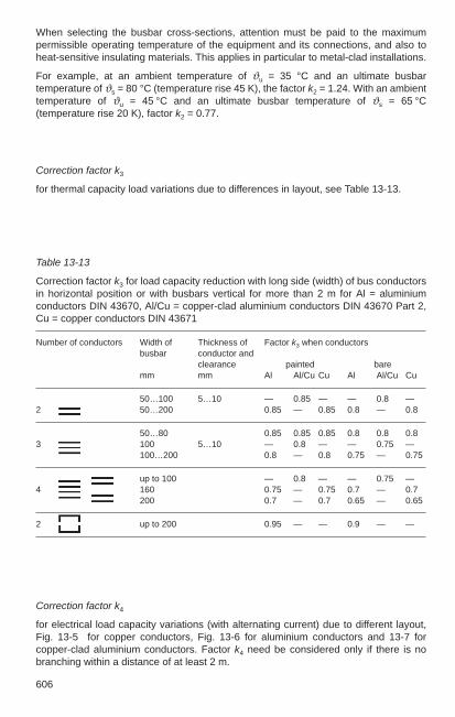
606
When selecting the busbar cross-sections, attention must be paid to the maximumpermissible operating temperature of the equipment and its connections, and also toheat-sensitive insulating materials. This applies in particular to metal-clad installations.
For example, at an ambient temperature of ϑu = 35 °C and an ultimate busbartemperature of ϑs = 80 °C (temperature rise 45 K), the factor k2 = 1.24. With an ambienttemperature of ϑu = 45 °C and an ultimate busbar temperature of ϑs = 65 °C(temperature rise 20 K), factor k2 = 0.77.
Correction factor k4
for electrical load capacity variations (with alternating current) due to different layout,Fig. 13-5 for copper conductors, Fig. 13-6 for aluminium conductors and 13-7 forcopper-clad aluminium conductors. Factor k4 need be considered only if there is nobranching within a distance of at least 2 m.
Table 13-13
Correction factor k3 for load capacity reduction with long side (width) of bus conductorsin horizontal position or with busbars vertical for more than 2 m for Al = aluminiumconductors DIN 43670, Al/Cu = copper-clad aluminium conductors DIN 43670 Part 2,Cu = copper conductors DIN 43671
Number of conductors Width of Thickness of Factor k3 when conductorsbusbar conductor and
clearance painted baremm mm Al Al/Cu Cu Al Al/Cu Cu
50…100 5…10 — 0.85 — — 0.8 —2 50…200 0.85 — 0.85 0.8 — 0.8
50…80 0.85 0.85 0.85 0.8 0.8 0.83 100 5…10 — 0.8 — — 0.75 —
100…200 0.8 — 0.8 0.75 — 0.75
up to 100 — 0.8 — — 0.75 —4 160 0.75 — 0.75 0.7 — 0.7
200 0.7 — 0.7 0.65 — 0.65
2 up to 200 0.95 — — 0.9 — —
Correction factor k3
for thermal capacity load variations due to differences in layout, see Table 13-13.

13
607
Fig. 13-5
Correction factor k4 for reduction in load with alternating current up to 60 Hz due toadditional skin effect in Cu conductors with small phase centre-line distance a:
a) Examples: Three-phase busbar with n = 3 conductors per phase and conductorthickness s in direction of phase centre-line distance a (above); AC single-phasebusbar with n = 2 conductors per phase and conductor thickness s at right angles tophase centre-line distance a (below), b) Factor k4 for conductors of s = 5 mm, and c)Factor k4 for conductors of s = 10 mm as a function of b · h/a2; a, b and h in mm;parameter n = number of conductors per phase.
Correction factor k5
Influences specific to the location (altitude, exposure to sun, etc.) can be allowed forwith factor k5 as given in Table 13-14.
Table 13-14
Correction factor k5 for reduction in load capacity at altitudes above 1000 m.
Height above sea-level Factor k5 Factor k5
m indoors outdoors1)
1 000 1.00 0.982 000 0.99 0.943 000 0.96 0.894 000 0.90 0.83
1) Reduction smaller at geogr. latitude above 60 ° and/or with heavily dust-laden air.
n=2 and 3
0,2
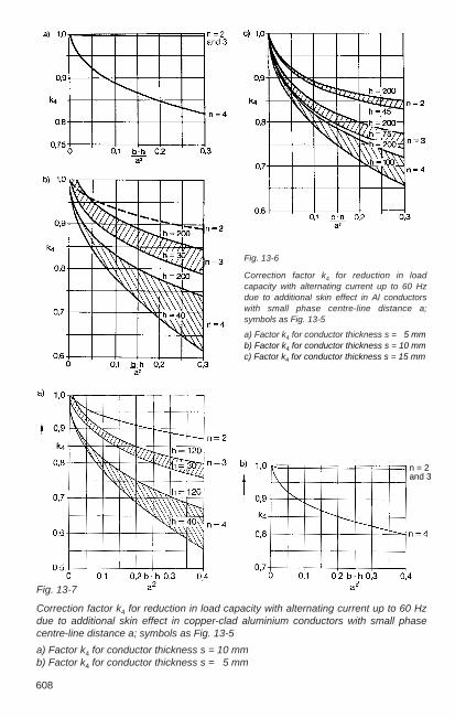
608
Fig. 13-7
Correction factor k4 for reduction in load capacity with alternating current up to 60 Hzdue to additional skin effect in copper-clad aluminium conductors with small phasecentre-line distance a; symbols as Fig. 13-5
a) Factor k4 for conductor thickness s = 10 mm b) Factor k4 for conductor thickness s = 5 mm
Fig. 13-6
Correction factor k4 for reduction in loadcapacity with alternating current up to 60 Hzdue to additional skin effect in Al conductorswith small phase centre-line distance a;symbols as Fig. 13-5
a) Factor k4 for conductor thickness s = 15 mm b) Factor k4 for conductor thickness s = 10 mm c) Factor k4 for conductor thickness s = 15 mm
n = 2and 3
13
645645
13.2 Cables, wires and flexible cords
13.2.1 Specifications, general
During the course of implementing the unified internal European market, there havebeen changes in the standardization of low and medium-voltage cables. The sectionsrelevant after implementation of the corresponding European harmonization document(HD) for Germany have been collected in a new VDE regulation DIN VDE 0276:
Product group Former standards Voltage series New VDE regulation DIN VDE ... (kV) DIN VDE ...
PVC cable 0271 1 0276 Part 603 (number of cores 4) 0276 Part 627 (number of cores 4)
XLPE cable 0272 1 0276 Part 603XLPE cable 0273 10, 20, 30 0276 Part 620XLPE cable 0255 10, 20, 30 0276 Part 621
Cables, wires and flexible cords often have to satisfy very different requirementsthroughout the cable route. Before deciding the type and cross-section, therefore, onemust examine their particular electrical function and also climatic and operationalfactors influencing system reliability and the expected life time of the equipment. Criticalstresses at places along the route can endanger the entire link. Particularly importantare the specified conditions for heat dissipation.
In the VDE specifications, the codes for the construction, properties and current-carrying capacity of power cables and wires are contained in Group 2 “Power guides”,and for cables and wires in telecommunications and information processing systems inGroup 8 “Information technology”.
The identification codes for cables are obtained by adding the symbols in Table 13-43to the initial letter “N” (types according to DIN VDE) in the sequence of theircomposition, starting from the conductor. Copper conductors are not identified in thetype designation. With paper-insulated cables, the form of insulation is also notmentioned in the code.
Recommendations for the use, supply, transportation and installation and for thecurrent-carrying capacity of cables can be found in the relevant sections of the VDEregulation DIN VDE 0276 and the VDE regulations for installation. Applicationinformation for flexible cords is given in DIN VDE 0298-3. The guidelines for up to 1000V also contain notes on the selection of overload and short-circuit protection facilities.

646
Table 13-43
Code symbols for cables
Codes for plastic-insulated cables
A Aluminium conductorI House wiring cableY Insulation of thermoplastic polyvinyl chloride (PVC) 2Y Insulation of thermoplastic polyethylene (PE) 2X Insulation of cross-linked polyethylene (XLPE) HX Insulation of cross-linked halogen-free polymerC Concentric copper conductor CW Concentric copper conductor, meander-shaped appliedS Copper screen SE Copper screen, applied over each core of three-core cables (F) Screen area longitudinally watertightY Protective PVC inner sheathF Armouring of galvanized flat steel wire R Armouring of galvanized round steel wire G Counter tape or binder of galvanized steel stripY PVC outer sheath2Y PE outer sheathH Outer sheath of thermoplastic halogen-free polymerHX Outer sheath of cross-linked halogen-free polymer–FE Insulation maintained in case of fire
Codes for paper-insulated cables
A Aluminium conductorH Screening for Höchstädter cableE Metal sheath over each core (three-sheath cable)K Lead sheathE Protective cover with embedded layer of elastomer tape or plastic foilY Protective PVC inner sheathB Armouring of steel stripF Armouring of galvanized flat steel wireFO Armouring of galvanized flat steel wire, openG Counter tape or binder of steel stripA Protective cover of fibrous materialY PVC outer sheathYV Reinforced PVC outer sheath
For cables U0/U 0.6/1 kV without concentric conductor
–J Cable with core coded green/yellow–O Cable without core coded green/yellow
Codes for conductor shape and type
RE Solid round conductorRM Stranded round conductorSE Solid sector-shaped conductorSM Stranded sector-shaped conductorRF Flexible stranded round conductor

13
647647
13.2.2 Current-carrying capacity
Specifications for the “rated currents” and the conversion factors in the case ofdeviations in operating conditions are to be found in the following VDE regulations:
DIN VDE 0276-603: for PVC cables (number of cores 4) and XLPE cables 1 kVDIN VDE 0276-604: for cables with improved behaviour in case of fire for 1 kV DIN VDE 0276-620: for XLPE cables 10, 20 and 30 kV and for PVC cables 10 kVDIN VDE 0276-621: for paper-insulated cables 10, 20 and 30 kVDIN VDE 0276-622: for cables with improved behaviour in case of fire for power
plants 10, 20 and 30 kVDIN VDE 0276-627: for PVC cables (number of cores 4) 1 kV DIN VDE 0271: for PVC cables 1 kV (special designs) and PVC cables to 6 kVDIN VDE 0276-1000: conversion factors (current-carrying capacity)DIN VDE 0298-4: for lines
The values for the current capacity of cables laid underground can be found in Tables 13-44, and 13-46 to 13-49. They are applicable for a load factor of m = 0.7(electrical utility load), for a specific ground thermal resistance of 1 K · m/W, for aground temperature of 20 °C and for laying at a depth of 0.7 m to 1.2 m. The electricalutility load (load factor m = 0.7) is based on a load curve that is usual in power supplycompany networks; see Fig. 13-8. The load factor is calculated from the 24-hour loadcycle and is a quotient of the “area under the load curve” to “total area of the rectangle(maximum load × 24 h)”.
Fig. 13-8
24-hour load cycle and calculating of the load factor (example for a load factor of 0.73)
load
/max
imum
load
ratio of load to maximum load in % ratio of average load to maximum load
load
fact
or

648
The values for the current capacity of cables laid in air can be found in Tables 13-45 to13-49. They are applicable for three-phase continuous operation at an ambienttemperature of 30 °C.
Different conditions must be taken into account by application of conversion factors tothe above current rating values.
For multiconductor cables the conversion factors given in Table 13-50 apply.The following apply for cables laid in air– for different ambient temperatures, the conversion factors given in Table 13-51 and– for the influence of laying and grouping the conversion factors from Tables 13-52 and
13-53.
The following applies for underground cables:– for different ground temperatures, the conversion factor f1 given in Tables 13-54 and
13-55 and– for cables laying and grouping, the conversion factor f2 given in Tables 13-56 to
13-59Both factors also include the ground conditions and the configuration of the cables inthe ground. Therefore, both conversion factors, f1 and f2, must be always used.
Additional conversion factors for laying cables underground may be:– 0.85 when laying cables in conduits– 0.9 when laying cables under covers with air space.
Examples for calculating the permissible current-carrying capacity:Example 1Current-carrying capacity of XLPE cable N2XSY 1 × 240 RM/25 6/10 kV:Operating conditions: cables laid in trefoil formation in ground, covers containing air,load factor m = 0.7, specific soil thermal resistance 1.5 K · m/W, soil temperature 25 °C,4 systems next to each other, spacing 7 cm.1. Current rating from Table 13-47, column 10 526 A2. Conversion factor f1 for 25 °C ground temperature and a max.
operating temperature of 90 °C, soil thermal resistance 1.5 K · m/W,load factor m = 0.7, from Table 13-54, column 5 0.87
3. Conversion factor for grouping f2 for 4 parallel systems as in Table 13-56, column 5 (1.5/0.7) 0.70
4. Reduction factor for protective shells 0.905. Max. permitted capacity: 526 A × 0.87 × 0.70 × 0.9 = 288 A
Example 2Current rating for PVC cable NYY-J 3 × 120 SM/70 SM 0.6/1kVOperating conditions: cables laid in air, ambient temperature 40 °C, 3 cables on a cablerack with unimpeded air circulation, spacing = cable outside diameter, two cable racks1. Current rating from Table 13-45, column 3 285 A2. Conversion factor for 40 °C from Table 13-51, column 10 0.873. Conversion factor for laying and grouping from Table 13-53,
column 5 0.984. Reduced current rating: 285 A × 0.87 × 0.98 = 243 A

13
649649
Table 13-44
Rated current (three-phase operation) as per DIN VDE 0276-603 cables with U0 /U = 0.6 /1 kV laid underground
1 2 3 4 5 6 7 8 9
Insulation material PVC VPE
Permissible operating temperature 70 °C 90 °C
Type designation N(A)YY N(A)YCWY3) N(A)2XY; N(A)2X2Y
Configuration
Number of loaded conductors 1 3 3 3 3 1 3 3
Cross-section in mm2 Copper conductor: rated current in A
1.5 41 27 30 27 31 48 31 332.5 55 36 39 36 40 63 40 42
4 71 47 50 47 51 82 52 546 90 59 62 59 63 102 64 57
10 124 79 83 79 84 136 86 8916 160 102 107 102 108 176 112 11525 208 133 138 133 139 229 145 14835 250 159 164 160 166 275 174 17750 296 188 195 190 196 326 206 20970 365 232 238 234 238 400 254 25695 438 280 286 280 281 480 305 307
120 501 318 325 319 315 548 348 349150 563 359 365 357 347 616 392 393185 639 406 413 402 385 698 444 445240 746 473 479 463 432 815 517 517300 848 535 541 518 473 927 585 583400 975 613 614 579 521 1064 671 663500 1125 687 693 624 574 1227 758 749
Cross-section in mm2 Aluminium conductor: rated current in A
25 160 102 106 103 108 177 112 11435 193 123 127 123 129 212 135 13650 230 144 151 145 153 252 158 16270 283 179 185 180 187 310 196 19995 340 215 222 216 223 372 234 238
120 389 245 253 246 252 425 268 272150 436 275 284 276 280 476 300 305185 496 313 322 313 314 541 342 347240 578 364 375 362 358 631 398 404300 656 419 425 415 397 716 457 457400 756 484 487 474 441 825 529 525500 873 553 558 528 489 952 609 601
Conversion factors
f1 2) from tables 13-54 13-54 13-54 13-54 13-54 13-54 13-54 13-54
f2 3) from tables 13-59 13-59 13-56 13-59 13-56 13-59 13-59 13-56
13-57 13-57 13-57
1) Rated current in DC systems with remote return conductors 2) for ground temperature 3) for grouping
1) 1)

650
Table 13-45
Rated current (three-phase operation) as per DIN VDE 0276-603 cables with U0 /U = 0.6 /1 kV laid in air
1 2 3 4 5 6 7 8 9
Insulation material PVC VPE
Permissible operating temperature 70°C 90°C
Type designation N(A)YY N(A)YCWY3) N(A)2XY; N(A)2X2Y
Configuration
Number of loaded conductors 1 3 3 3 3 1 3 3
Cross-section in mm2 Copper conductor: rated current in A
1.5 27 19.5 21 19.5 22 33 24 262.5 35 25 28 26 29 43 32 344 47 34 37 34 39 57 42 446 59 43 47 44 49 72 53 56
10 81 59 64 60 67 99 74 7716 107 79 84 80 89 131 98 10225 144 106 114 108 119 177 133 13835 176 129 139 132 146 217 162 17050 214 157 169 160 177 265 197 20770 270 199 213 202 221 336 250 26395 334 246 264 249 270 415 308 325
120 389 285 307 289 310 485 359 380150 446 326 352 329 350 557 412 437185 516 374 406 377 399 646 475 507240 618 445 483 443 462 774 564 604300 717 511 557 504 519 901 649 697400 843 597 646 577 583 1060 761 811500 994 669 747 626 657 1252 866 940
Cross-section in mm2 Aluminium conductor: rated current in A
25 110 82 87 83 91 136 102 10635 135 100 107 101 112 166 126 13050 166 119 131 121 137 205 149 16170 210 152 166 155 173 260 191 20495 259 186 205 189 212 321 234 252
120 302 216 239 220 247 376 273 295150 345 246 273 249 280 431 311 339185 401 285 317 287 321 501 360 395240 479 338 378 339 374 600 427 472300 555 400 437 401 426 696 507 547400 653 472 513 468 488 821 600 643500 772 539 600 524 556 971 695 754
Conversion factors
f 2) from tables 13-51 13-51 13-51 13-51 13-51 13-51 13-51 13-51 f 3) from tables 13-53 13-53 13-52 13-53 13-52 13-53 13-53 13-52
1) Rated current in DC systems with remote return conductors 2) for air temperature 3) for grouping
1) 1)

13
651651
Table 13-46
Rated current (three-phase operation) as per DIN VDE 0271 cables with U0 /U = 3.6 /6 kV laid underground and in air
1 2 3
Insulation material PVC
Metal sheath —
Type designation NYFY3); NYSYPermissible operating temperature 70 °C
Configuration
Laying in ground in air
Nominal cross-section of copper conductor mm2 rated current in A
1 25 129 1051 35 155 1281 50 184 1551 70 227 196
1 95 272 242120 309 280150 346 319185 390 366
240 449 430300 502 489400 562 560
Conversion factors
f1/ f 1) from tables 13-54 13-51f2/ f 2) from tables 13-59 13-53
1) for ground temperature/for air temperature 2) for grouping in ground/in air3) three-core

652
Table 13-47
Rated current (three-phase operation) as per DIN VDE 0276-620 (PVC and XLPE cable) and DIN VDE 0276-621 (paper cable) cable with U0 /U = 6/10 kVlaid underground and in air
1 2 3 4 5 6 7 8 9 10 11 12
Insulation mat. Impreg. PVC XL PEpaper
Metal sheath Lead
Type N(A)KBA N(A)YSEY3) N(A)2XSEY, N(A)2XSE2Y3)
designation N(A)YSY4) N(A)2XSY, N(A)2XS2Y4)
Permissible 65 °C 70 °C 90 °Coperating temp.
Configuration
Installation Ground Air Ground Air Ground Air Ground Air Ground Air Ground Air
Nominal Rated current in Across-sectionCopper mm2
1 25 122 100 134 114 137 119 151 147 157 163 179 194135 150 123 160 138 163 143 181 178 187 197 212 23550 179 148 189 165 192 172 213 213 220 236 249 28270 222 187 231 205 234 214 261 265 268 294 302 35095 269 228 276 249 279 261 312 322 320 358 359 426
120 308 263 313 286 316 301 355 370 363 413 405 491150 347 301 351 324 352 341 399 420 405 468 442 549185 392 345 396 371 397 391 451 481 456 535 493 625240 454 408 458 434 457 460 523 566 526 631 563 731300 511 467 — — 512 526 590 648 591 722 626 831400 577 536 — — 571 602 — — 662 827 675 920500 — — — — 639 691 — — 744 949 748 1043
Aluminium mm2
1 25 195 178 — — — — — — — — — —135 117 196 — — — — 140 138 145 153 165 182150 139 115 147 128 149 133 165 165 171 183 194 21070 173 145 179 159 182 166 203 206 208 228 236 27395 209 177 214 193 217 203 242 249 248 278 281 333
120 240 205 244 222 246 234 276 288 283 321 318 384150 270 234 273 252 276 266 309 326 315 364 350 432185 307 270 309 289 311 306 351 375 357 418 394 496240 357 320 358 340 359 361 408 442 413 494 452 583300 403 368 404 389 405 415 463 507 466 568 506 666400 461 428 — — 457 481 — — 529 660 558 755500 — — — — 520 560 — — 602 767 627 868
Conversion factors from tables
f1/ f 1) 13-54 13-51 13-55 13-51 13-54 13-51 13-54 13-51 13-54 13-51 13-54 13-51f2/ f 2) 13-59 13-53 13-59 13-53 13-56 13-52 13-59 13-53 13-56 13-52 13-58 13-52
13-57 13-57
1) for ground temperature/for air temperature 3) three-core2) for grouping in ground/in air 4) single-core

13
653653
Table 13-48
Rated current (three-phase operation) as per DIN VDE 0276-620 (XLPE cables) andDIN VDE 0276-621 (paper cable) cable with U0 /U = 12/20 kV laid underground and in air
1 2 3 4 5 6 7
Insulation material Impregnated paper XLPE
Metal sheath Lead
Type designation N(A)EKBA N(A)2XSY, N(A)2XS2YN(A)2X(F)2Y
Permissible 65 °C 90 °Coperating temperature
Configuration
Installation Ground Air Ground Air Ground Air
Nominal cross-section Rated current in ACopper conductor mm2
125 129 111 — — — —35 155 134 189 200 213 23550 185 161 222 239 250 28270 229 200 271 297 303 35195 274 243 323 361 360 426
120 314 279 367 416 407 491150 354 317 409 470 445 549185 402 363 461 538 498 625240 468 426 532 634 568 731300 530 488 599 724 633 830400 600 560 671 829 685 923500 674 641 754 953 760 1045
Aluminium conductor mm2
25 100 86 — — — —35 121 104 — — — —50 144 125 172 185 195 21970 178 156 210 231 237 27395 213 189 251 280 282 332
120 244 218 285 323 319 384150 275 247 319 366 352 432185 314 284 361 420 396 494240 367 334 417 496 455 581300 417 384 471 569 510 663400 478 445 535 660 564 753500 545 516 609 766 634 866
Conversion factors
f1/ f 1) from tables 13-54 13-51 13-54 13-51 13-54 13-51 f2/ f 2) from tables 13-59 13-53 13-56 13-52 13-58 13-52
13-57
1) for ground temperature/for air temperature 2) for grouping in ground/in air

654
Table 13-49
Rated current (three-phase operation) as per DIN VDE 0276-620 (XLPE cables) andDIN VDE 0276-621 (paper cable) cable with U0 /U = 18/30 kV laid underground and in air
1 2 3 4 5 6 7
Insulation material Impregnated paper XLPE
Metal sheath Lead
Type designation N(A)EKEBA N(A)2XSY, N(A)2XS2YN(A)2XS(F)2Y
Permissible 60 °C 90 °Coperating temperature
Configuration
Installation Ground Air Ground Air Ground Air
Nominal cross-section Rated current in ACopper conductor mm2
135 146 126 — — — —50 174 150 225 241 251 28270 215 187 274 299 304 35095 259 227 327 363 362 425
120 297 261 371 418 409 488150 334 295 414 472 449 548185 379 338 466 539 502 624240 442 397 539 635 574 728300 501 453 606 725 640 828400 569 519 680 831 695 922500 644 594 765 953 773 1045
Aluminium conductor mm2
35 113 98 — — — —50 135 117 174 187 195 21970 167 145 213 232 238 27395 201 176 254 282 283 331
120 231 203 289 325 321 382150 260 230 322 367 354 429185 297 264 364 421 399 492240 347 311 422 496 458 578300 394 356 476 568 514 659400 454 414 541 650 570 750500 520 478 616 764 642 861
Conversion factors
f1/ f 1) from tables 13-54 13-51 13-54 13-51 13-54 13-51 f2/ f 2) from tables 13-59 13-53 13-56 13-52 13-58 13-52
13-57
1) for ground temperature/for air temperature 2) for grouping in ground/in air
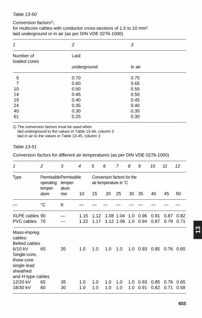
13
655655
Table 13-50
Conversion factors1),for multicore cables with conductor cross-sections of 1.5 to 10 mm2
laid underground or in air (as per DIN VDE 0276-1000)
1 2 3
Number of Laidloaded cores
underground in air
5 0.70 0.757 0.60 0.65
10 0.50 0.5514 0.45 0.5019 0.40 0.4524 0.35 0.4040 0.30 0.3561 0.25 0.30
1) The conversion factors must be used whenlaid underground to the values in Table 13-44, column 3laid in air to the values in Table 13-45, column 3
Table 13-51
Conversion factors for different air temperatures (as per DIN VDE 0276-1000)
1 2 3 4 5 6 7 8 9 10 11 12
Type PermissiblePermissible Conversion factors for the operating temper- air temperature in °Ctemper- atureature rise 10 15 20 25 30 35 40 45 50
— °C K — — — — — — — — —
XLPE cables 90 — 1.15 1.12 1.08 1.04 1.0 0.96 0.91 0.87 0.82PVC cables 70 — 1.22 1.17 1.12 1.06 1.0 0.94 0.87 0.79 0.71
Mass-impreg.cables:Belted cables6/10 kV 65 35 1.0 1.0 1.0 1.0 1.0 0.93 0.85 0.76 0.65Single-core,three-core single leadsheathedand H-type cables12/20 kV 65 35 1.0 1.0 1.0 1.0 1.0 0.93 0.85 0.76 0.6518/30 kV 60 30 1.0 1.0 1.0 1.0 1.0 0.91 0.82 0.71 0.58

656
Table 13-52
Conversion factors for grouping in air1), single-core cables in three-phase systems (asper DIN VDE 0276-1000)
1 2 3 4 5
Installation in flat formation Number of Number of troughs/ systems2)
Spacing = racks horizontal cable diameter d vertical 1 2 3
Laid on the floor 1 0.92 0.89 0.88
Unperforated 1 0.92 0.89 0.88cable troughs3)
2 0.87 0.84 0.83
3 0.84 0.82 0.81
6 0.82 0.80 0.79
Perforated 1 1.00 0.93 0.90cable troughs3)
2 0.97 0.89 0.85
3 0.96 0.88 0.82
6 0.94 0.85 0.80
Cable racks4) 1 1.00 0.97 0.96
2 0.97 0.94 0.93
3 0.96 0.93 0.92
6 0.94 0.91 0.90
On racks or Number of Number of systemson the wall or troughs verticalon perforated cable horizontal 1 2 3troughs in vertical
1 0.94 0.91 0.89configuration
2 0.94 0.90 0.86
1) If the air temperature is increased by the heat loss of the cables in small buildings or because of high grouping, theconversion factors for different air temperatures in Table 13-51 must also be used.
2) Factors as per DIN VDE 0255 (VDE 0255)3) A cable trough is a continuous surface with raised edges but no cover. A cable trough is considered perforated if it is
perforated over at least 30 % of the entire surface area.4) A cable rack is a support structure in which the supporting area is no more than 10% of the total area of the structure.When cables with metal sheathing or shielding are laid flat, the increased sheathing or shielding losses act against thereduced mutual heating when the spacing is increased. For this reason no information on reduction-free configurations canbe given.
(continued)
a ≥ 20 mm
a ≥ 20 mm
a ≥ 20 mm
a ≥ 20 mm
≥ 225 mm
≥30
0 m
m≥
300
mm
≥30
0 m
m
d d
a
d d
a
d d
a
d d
a
dd

13
657657
Table 13-52 (continued)
Conversion factors for grouping in air1), single-core cables in three-phase systems (asper DIN VDE 0276-1000)
6 7 8 9 10
Installation in trefoil formation Number of Number oftroughs/ systems2)
Spacing = racks horizontal2 · cable diameter d vertical 1 2 3
Laid on the floor 1 0.98 0.96 0.94
Unperforated 1 0.98 0.96 0.94cable troughs3)
2 0.95 0.91 0.87
3 0.94 0.90 0.85
6 0.93 0.88 0.82
Perforated 1 1.00 0.98 0.96cable troughs3)
2 0.97 0.93 0.89
3 0.96 0.92 0.85
6 0.95 0.90 0.83
Cable racks4) 1 1.00 0.97 0.96(cable gratings)
2 0.97 0.95 0.93
3 0.96 0.94 0.90
6 0.95 0.93 0.87
On racks or Number of Number of systemson the wall or troughs verticalon perforated cable horizontal 1 2 3troughs in vertical
1 1.00 0.91 0.89configuration
2 1.00 0.90 0.86
1) If the air temperature is increased by the heat loss of the cables in small buildings or because of high grouping, theconversion factors for different air temperatures in Table 13-51 must also be used.
2) Factors as in CENELEC Report R064.001 re HD 384,5.523:1991.3) A cable trough is a continuous surface with raised edges but no cover. A cable trough is considered perforated if the
perforations cover at least 30 % of the entire surface area.4) A cable rack is a support structure in which the supporting area is no more than 10 % of the total area of the structure.Load reduction is not required when laying in bundles where the spacing of adjacent systems is at least four times the cablediameter, as long as the ambient temperature is not increased by the heat loss (see footnote 1).
a ≥ 20 mm
a ≥ 20 mm
a ≥ 20 mm
a ≥ 20 mm
≥ 225 mm
≥30
0 m
m≥
300
mm
≥30
0 m
m
2d 2d
a
2d 2d
a
2d 2d
a
2d 2d
a
2d

658
Table 13-53
Conversion factors for grouping in air1), multicore cables and single-core DC cables(as per DIN VDE 0276-1000)
1 2 3 4 5 6 7
Installation Number of Number of cables troughs/ horizontal4)
Spacing = rackscable diameter d vertical 1 2 3 4 6
Laid on the floor 1 0.97 0.96 0.94 0.93 0.90
Unperforated 1 0.97 0.96 0.94 0.93 0.90cable troughs2)
2 0.97 0.95 0.92 0.90 0.86
3 0.97 0.94 0.91 0.89 0.84
6 0.97 0.93 0.90 0.88 0.83
Perforated 1 1.00 1.00 0.98 0.95 0.91cable troughs2)
2 1.00 0.99 0.96 0.92 0.87
3 1.00 0.98 0.95 0.91 0.85
6 1.00 0.97 0.94 0.90 0.84
Cable racks3) 1 1.00 1.00 1.00 1.00 1.00(cable gratings)
2 1.00 0.99 0.98 0.97 0.96
3 1.00 0.98 0.97 0.96 0.93
6 1.00 0.97 0.96 0.94 0.91
Number of Number of systems troughs vertical
horizontal 1 2 3 4 6
1 1.00 0.91 0.89 0.88 0.87
2 1.00 0.91 0.88 0.87 0.85
1) If the air temperature is increased by the heat loss of the cables in small buildings or because of high grouping, theconversion factors for different air temperatures in Table 13-51 must also be used.
2) A cable trough is a continuous surface with raised edges but no cover. A cable trough is considered perforated if it isperforated over at least 30 % of the entire surface area.
3) A cable rack is a support structure in which the supporting area is no more than 10 % of the total area of the structure.4) Factors as in CENELEC Report R064.001 re HD 384.5.523:1991.Load reduction is not required where the horizontal or vertical spacing of adjacent cables is at least twice the cablediameter, as long as the ambient temperature is not increased by the heat loss (see footnote 1).
(continued)
≥ 225 mm
≥30
0 m
m
a ≥ 20 mm
d d
a
a ≥ 20 mm
d d
a
≥30
0 m
m
a ≥ 20 mm
d d
a
≥30
0 m
m
a ≥ 20 mm
d d
a
dd
On racks oron the wall oron perforated cable troughs in verticalconfiguration
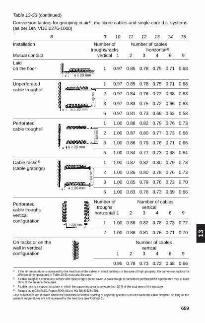
13
659659
Table 13-53 (continued)
Conversion factors for grouping in air1), multicore cables and single-core d.c. systems(as per DIN VDE 0276-1000)
8 9 10 11 12 13 14 15
Installation Number of Number of cables troughs/racks horizontal4)
Mutual contact vertical 1 2 3 4 6 9
Laid on the floor 1 0.97 0.85 0.78 0.75 0.71 0.68
Unperforated 1 0.97 0.85 0.78 0.75 0.71 0.68cable troughs2)
2 0.97 0.84 0.76 0.73 0.68 0.63
3 0.97 0.83 0.75 0.72 0.66 0.63
6 0.97 0.81 0.73 0.69 0.63 0.58
Perforated 1 1.00 0.88 0.82 0.79 0.76 0.73cable troughs2)
2 1.00 0.87 0.80 0.77 0.73 0.68
3 1.00 0.86 0.79 0.76 0.71 0.66
6 1.00 0.84 0.77 0.73 0.68 0.64
Cable racks3) 1 1.00 0.87 0.82 0.80 0.79 0.78(cable gratings)
2 1.00 0.86 0.80 0.78 0.76 0.73
3 1.00 0.85 0.79 0.76 0.73 0.70
6 1.00 0.83 0.76 0.73 0.69 0.66
Number of Number of cables troughs vertical
horizontal 1 2 3 4 6 9
1 1.00 0.88 0.82 0.78 0.73 0.72
2 1.00 0.88 0.81 0.76 0.71 0.70
Number of cables vertical
1 2 3 4 6 9
0.95 0.78 0.73 0.72 0.68 0.661) If the air temperature is increased by the heat loss of the cables in small buildings or because of high grouping, the conversion factors for
different air temperatures in Table 13-51 must also be used.2) A cable trough is a continuous surface with raised edges but no cover. A cable trough is considered perforated if it is perforated over at least
30 % of the entire surface area.3) A cable rack is a support structure in which the supporting area is no more than 10 % of the total area of the structure.4) Factors as in CENELEC Report R064.001 re HD 384,5.523:1991.Load reduction is not required where the horizontal or vertical spacing of adjacent systems is at least twice the cable diameter, so long as theambient temperatures are not increased by the heat loss (see footnote 1).
On racks or on thewall in verticalconfiguration
Perforatedcable troughsverticalconfiguration
a ≥ 20 mm
a ≥ 20 mm
a ≥ 20 mm
a ≥ 20 mm
≥ 225 mm
≥30
0 m
m
≥30
0 m
m≥
300
mm
a
a
a
a
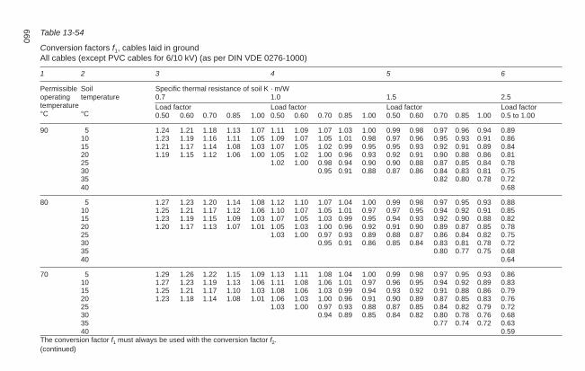
660 Table 13-54
Conversion factors f1, cables laid in groundAll cables (except PVC cables for 6/10 kV) (as per DIN VDE 0276-1000)
1 2 3 4 5 6
Permissible Soil Specific thermal resistance of soil K · m/Woperating temperature 0.7 1.0 1.5 2.5temperature Load factor Load factor Load factor Load factor°C °C 0.50 0.60 0.70 0.85 1.00 0.50 0.60 0.70 0.85 1.00 0.50 0.60 0.70 0.85 1.00 0.5 to 1.00
90 5 1.24 1.21 1.18 1.13 1.07 1.11 1.09 1.07 1.03 1.00 0.99 0.98 0.97 0.96 0.94 0.8910 1.23 1.19 1.16 1.11 1.05 1.09 1.07 1.05 1.01 0.98 0.97 0.96 0.95 0.93 0.91 0.8615 1.21 1.17 1.14 1.08 1.03 1.07 1.05 1.02 0.99 0.95 0.95 0.93 0.92 0.91 0.89 0.8420 1.19 1.15 1.12 1.06 1.00 1.05 1.02 1.00 0.96 0.93 0.92 0.91 0.90 0.88 0.86 0.8125 1.02 1.00 0.98 0.94 0.90 0.90 0.88 0.87 0.85 0.84 0.7830 0.95 0.91 0.88 0.87 0.86 0.84 0.83 0.81 0.7535 0.82 0.80 0.78 0.7240 0.68
80 5 1.27 1.23 1.20 1.14 1.08 1.12 1.10 1.07 1.04 1.00 0.99 0.98 0.97 0.95 0.93 0.8810 1.25 1.21 1.17 1.12 1.06 1.10 1.07 1.05 1.01 0.97 0.97 0.95 0.94 0.92 0.91 0.8515 1.23 1.19 1.15 1.09 1.03 1.07 1.05 1.03 0.99 0.95 0.94 0.93 0.92 0.90 0.88 0.8220 1.20 1.17 1.13 1.07 1.01 1.05 1.03 1.00 0.96 0.92 0.91 0.90 0.89 0.87 0.85 0.7825 1.03 1.00 0.97 0.93 0.89 0.88 0.87 0.86 0.84 0.82 0.7530 0.95 0.91 0.86 0.85 0.84 0.83 0.81 0.78 0.7235 0.80 0.77 0.75 0.6840 0.64
70 5 1.29 1.26 1.22 1.15 1.09 1.13 1.11 1.08 1.04 1.00 0.99 0.98 0.97 0.95 0.93 0.8610 1.27 1.23 1.19 1.13 1.06 1.11 1.08 1.06 1.01 0.97 0.96 0.95 0.94 0.92 0.89 0.8315 1.25 1.21 1.17 1.10 1.03 1.08 1.06 1.03 0.99 0.94 0.93 0.92 0.91 0.88 0.86 0.7920 1.23 1.18 1.14 1.08 1.01 1.06 1.03 1.00 0.96 0.91 0.90 0.89 0.87 0.85 0.83 0.7625 1.03 1.00 0.97 0.93 0.88 0.87 0.85 0.84 0.82 0.79 0.7230 0.94 0.89 0.85 0.84 0.82 0.80 0.78 0.76 0.6835 0.77 0.74 0.72 0.6340 0.59
The conversion factor f1 must always be used with the conversion factor f2.(continued)

13
661661
Table 13-54 (continued)
1 2 3 4 5 6
Permissible Soil Specific thermal resistance of soil K · m/Woperating temperature 0.7 1.0 1.5 2.5temperature Load factor Load factor Load factor Load factor°C °C 0.50 0.60 0.70 0.85 1.00 0.50 0.60 0.70 0.85 1.00 0.50 0.60 0.70 0.85 1.00 0.5 to 1.00
65 5 1.31 1.27 1.23 1.16 1.09 1.14 1.11 1.09 1.04 1.00 0.99 0.98 0.96 0.94 0.92 0 8510 1.29 1.24 1.20 1.14 1.06 1.11 1.09 1.06 1.02 0.97 0.96 0.95 0.93 0.91 0.89 0.8215 1.26 1.22 1.18 1.11 1.04 1.09 1.06 1.03 0.98 0.94 0.93 0.91 0.90 0.88 0.85 0.7820 1.24 1.20 1.15 1.08 1.01 1.06 1.03 1.00 0.95 0.90 0.90 0.88 0.86 0.84 0.82 0.7425 1.03 1.00 0.97 0.92 0.87 0.86 0.84 0.83 0.80 0.78 0.7030 0.94 0.89 0.83 0.82 0.81 0.79 0.77 0.74 0.6535 0.75 0.72 0.70 0.6040 0.55
60 5 1.33 1.28 1.24 1.17 1.10 1.15 1.12 1.09 1.05 1.00 0.99 0.98 0.96 0.94 0.92 0.8410 1.30 1.26 1.21 1.14 1.07 1.12 1.09 1.06 1.02 0.97 0.96 0.94 0.93 0.90 0.88 0.8015 1.28 1.23 1.19 1.12 1.04 1.09 1.06 1.03 0.98 0.93 0.92 0.91 0.89 0.87 0.84 0.7620 1.25 1.21 1.16 1.09 1.01 1.06 1.03 1.00 0.95 0.90 0.89 0.87 0.86 0.83 0.80 0.7225 1.03 1.00 0.97 0.92 0.86 0.85 0.83 0.82 0.79 0.76 0.6730 0.93 0.88 0.82 0.81 0.79 0.78 0.75 0.72 0.6235 0.73 0.70 0.67 0.5740 0.51
With mass-impregnated cables, increasing the current rating at temperatures below 20 °C is subject to conditions. The conversion factor f1 must be applied onlytogether with conversion factor f2.
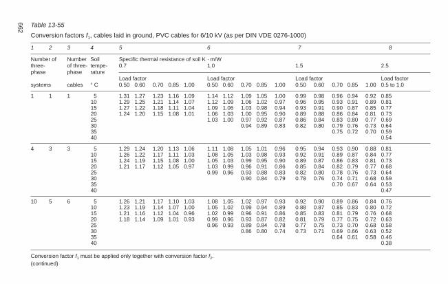
662 Table 13-55
Conversion factors f1, cables laid in ground, PVC cables for 6/10 kV (as per DIN VDE 0276-1000)
1 2 3 4 5 6 7 8
Number of Number Soil Specific thermal resistance of soil K · m/Wthree- of three- tempe- 0.7 1.0 1.5 2.5phase phase rature
Load factor Load factor Load factor Load factorsystems cables ° C 0.50 0.60 0.70 0.85 1.00 0.50 0.60 0.70 0.85 1.00 0.50 0.60 0.70 0.85 1.00 0.5 to 1.0
1 1 1 5 1.31 1.27 1.23 1.16 1.09 1.14 1.12 1.09 1.05 1.00 0.99 0.98 0.96 0.94 0.92 0.8510 1.29 1.25 1.21 1.14 1.07 1.12 1.09 1.06 1.02 0.97 0.96 0.95 0.93 0.91 0.89 0.8115 1.27 1.22 1.18 1.11 1.04 1.09 1.06 1.03 0.98 0.94 0.93 0.91 0.90 0.87 0.85 0.7720 1.24 1.20 1.15 1.08 1.01 1.06 1.03 1.00 0.95 0.90 0.89 0.88 0.86 0.84 0.81 0.7325 1.03 1.00 0.97 0.92 0.87 0.86 0.84 0.83 0.80 0.77 0.6930 0.94 0.89 0.83 0.82 0.80 0.79 0.76 0.73 0.6435 0.75 0.72 0.70 0.5940 0.54
4 3 3 5 1.29 1.24 1.20 1.13 1.06 1.11 1.08 1.05 1.01 0.96 0.95 0.94 0.93 0.90 0.88 0.8110 1.26 1.22 1.17 1.11 1.03 1.08 1.05 1.03 0.98 0.93 0.92 0.91 0.89 0.87 0.84 0.7715 1.24 1.19 1.15 1.08 1.00 1.05 1.03 0.99 0.95 0.90 0.89 0.87 0.86 0.83 0.81 0.7320 1.21 1.17 1.12 1.05 0.97 1.03 0.99 0.96 0.91 0.86 0.85 0.84 0.82 0.79 0.77 0.6825 0.99 0.96 0.93 0.88 0.83 0.82 0.80 0.78 0.76 0.73 0.6430 0.90 0.84 0.79 0.78 0.76 0.74 0.71 0.68 0.5935 0.70 0.67 0.64 0.5340 0.47
10 5 6 5 1.26 1.21 1.17 1.10 1.03 1.08 1.05 1.02 0.97 0.93 0.92 0.90 0.89 0.86 0.84 0.7610 1.23 1.19 1.14 1.07 1.00 1.05 1.02 0.99 0.94 0.89 0.88 0.87 0.85 0.83 0.80 0.7215 1.21 1.16 1.12 1.04 0.96 1.02 0.99 0.96 0.91 0.86 0.85 0.83 0.81 0.79 0.76 0.6820 1.18 1.14 1.09 1.01 0.93 0.99 0.96 0.93 0.87 0.82 0.81 0.79 0.77 0.75 0.72 0.6325 0.96 0.93 0.89 0.84 0.78 0.77 0.75 0.73 0.70 0.68 0.5830 0.86 0.80 0.74 0.73 0.71 0.69 0.66 0.63 0.5235 0.64 0.61 0.58 0.4640 0.38
Conversion factor f1 must be applied only together with conversion factor f2.(continued)

13
663663
Table 13-55 (continued)
1 2 3 4 5 6 7 8
Number of Number Soil Specific thermal resistance of soil K · m/Wthree- of three- tempe- 0.7 1.0 1.5 2.5phase phase rature
Load factor Load factor Load factor Load factorsystems cables ° C 0.50 0.60 0.70 0.85 1.00 0.50 0.60 0.70 0.85 1.00 0.50 0.60 0.70 0.85 1.00 0.5 to 1.0
— 8 10 5 1.23 1.19 1.14 1.07 . 0.99 1.05 1.02 0.99 0.94 0.89 0.88 0.86 0.85 0.82 0.80 0.7210 1.21 1.16 1.11 1.04 0.96 1.02 0.99 0.96 0.91 0.85 0.84 0.83 0.81 0.78 0.76 0 6715 1.18 1.13 1.09 1.01 0.93 0.99 0.96 0.92 0.87 0.82 0.81 0.79 0.77 0.74 0.72 0.6320 1.15 1.11 1.06 0.98 0.90 0.96 0.92 0.89 0.84 0.78 0.77 0.75 0.73 0.70 0.67 0.5725 0.92 0.89 0.85 0.80 0.74 0.73 0.71 0.69 0.66 0.63 0.5230 0.82 0.76 0.70 0.68 0.66 0.64 0 61 0.57 0.4535 0.60 0.56 0.52 0.3840 0.29
— 10 — 5 1.22 1.17 1.13 1.05 0.98 1.03 1.00 0.97 0.92 0.87 0.86 0.84 0.83 0.80 0.78 0.6910 1.19 1.15 1.10 1.02 0.94 1.00 0.97 0.94 0.89 0.83 0.82 0.81 0.79 0.76 0.73 0.6515 1.17 1.12 1.07 0.99 0.91 0.97 0.94 0.90 0.85 0.79 0.78 0.77 0.75 0.72 0.69 0.6020 1.14 1.09 1.04 0.96 0.88 0.94 0.90 0.87 0.81 0.76 0.74 0.73 0.71 0.68 0.65 0.5425 0.90 0.87 0.83 0.78 0.71 0.70 0.68 0.66 0.63 0.60 0.4830 0.79 0.73 0.67 0.66 0.63 0.61 0.58 0.54 0.4135 0.56 0.52 0.48 0.3340 0.22
Arrangement of three-phase systems in column 1 Arrangement of three-phase systems in column 2 Arrangement of three-phase cables in column 3
Conversion factor f1 must be applied only together with conversion factor f2.

664 Table 13-56
Conversion factor f2, cables laid in groundSingle-core cables in three phase systems, trefoil formation (as per DIN VDE 0276-1000)
1 2 3 4 5 6
Type Number Specific thermal resistance of soil in K · m/Wof systems 0.7 1.0 1.5 2.5
load factor load factor load factor load factor0.5 0.6 0.7 0.85 1.00 0.5 0.6 0.7 0.85 1.00 0.5 0.6 0.7 0.85 1.00 0.5 0.6 0.7 0.85 1.00
1 1.09 1.04 0.99 0.93 0.87 1.11 1.05 1.00 0.93 0.87 1.13 1.07 1.01 0.94 0.87 1.17 1.09 1.03 0.94 0.872 0.97 0.90 0.84 0.77 0.71 0.98 0.91 0.85 0.77 0.71 1.00 0.92 0.86 0.77 0.71 1.02 0.94 0.87 0.78 0.713 0.88 0.80 0.74 0.67 0.61 0.89 0.82 0.75 0.67 0.61 0.90 0.82 0.76 0.68 0.61 0.92 0.83 0.76 0.68 0.614 0.83 0.75 0.69 0.62 0.56 0.84 0.76 0.70 0.62 0.56 0.85 0.77 0.70 0.62 0.56 0.86 0.78 0.71 0.63 0.565 0.79 0.71 0.65 0.58 0.52 0.80 0.72 0.66 0.58 0.52 0.80 0.73 0.66 0.58 0.52 0.82 0.73 0.67 0.59 0.526 0.76 0.68 0.62 0.55 0.50 0.77 0.69 0.63 0.55 0.50 0.77 0.70 0.63 0.56 0.50 0.78 0.70 0.64 0.56 0.508 0.72 0.64 0.58 0.51 0.46 0.72 0.65 0.59 0.52 0.46 0.73 0.65 0.59 0.52 0.46 0.74 0.66 0.59 0.52 0.46
10 0.69 0.61 0.56 0.49 0.44 0.69 0.62 0.56 0.49 0.44 0.70 0.62 0.56 0.49 0.44 0.70 0.63 0.57 0.49 0.44
load factor load factor load factor load factor0.5 0.6 0.7 0.85 1.00 0.5 0.6 0.7 0.85 1.00 0.5 0.6 0.7 0.85 1.00 0.5 0.6 0.7 0.85 1.00
1 1.01 1.02 0.99 0.93 0.87 1.04 1.05 1.00 0.93 0.87 1.07 1.06 1.01 0.94 0.87 1.11 1.08 1.01 0.94 0.872 0.94 0.89 0.84 0.77 0.71 0.97 0.91 0.85 0.77 0.71 0.99 0.92 0.86 0.77 0.71 1.01 0.93 0.87 0.78 0.713 0.86 0.79 0.74 0.67 0.61 0.89 0.81 0.75 0.67 0.61 0.90 0.83 0.76 0.68 0.61 0.91 0.83 0.77 0.68 0.614 0.82 0.75 0.69 0.62 0.56 0.84 0.76 0.70 0.62 0.56 0.85 0.77 0.71 0.62 0.56 0.86 0.78 0.71 0.63 0.565 0.78 0.71 0.65 0.58 0.52 0.80 0.72 0.66 0.58 0.52 0.80 0.73 0.66 0.58 0.52 0.81 0.73 0.67 0.59 0.526 0.75 0.68 0.62 0.55 0.50 0.77 0.69 0.63 0.55 0.50 0.77 0.70 0.64 0.56 0.50 0.78 0.70 0.64 0.56 0.508 0.71 0.64 0.58 0.51 0.46 0.72 0.65 0.59 0.52 0.46 0.73 0.65 0.59 0.52 0.46 0.73 0.66 0.60 0.52 0.46
10 0.68 0.61 0.55 0.49 0.44 0.69 0.62 0.56 0.49 0.44 0.69 0.62 0.56 0.49 0.44 0.70 0.63 0.57 0.49 0.44
The conversion factor f2 must be applied only together with conversion factor f1.7
XLPE cables0.6/1 kV6/10 kV12/20 kV18/30 kV
PVC cables0.6/1 kV3.6/6 kV6/10 kV
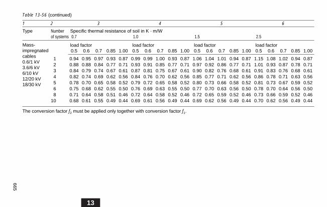
13
665
Table 13-56 (continued)
1 2 3 4 5 6
Type Number Specific thermal resistance of soil in K · m/Wof systems 0.7 1.0 1.5 2.5
load factor load factor load factor load factor0.5 0.6 0.7 0.85 1.00 0.5 0.6 0.7 0.85 1.00 0.5 0.6 0.7 0.85 1.00 0.5 0.6 0.7 0.85 1.00
1 0.94 0.95 0.97 0.93 0.87 0.99 0.99 1.00 0.93 0.87 1.06 1.04 1.01 0.94 0.87 1.15 1.08 1.02 0.94 0.872 0.88 0.88 0.84 0.77 0.71 0.93 0.91 0.85 0.77 0.71 0.97 0.92 0.86 0.77 0.71 1.01 0.93 0.87 0.78 0.713 0.84 0.79 0.74 0.67 0.61 0.87 0.81 0.75 0.67 0.61 0.90 0.82 0.76 0.68 0.61 0.91 0.83 0.76 0.68 0.614 0.82 0.74 0.69 0.62 0.56 0.84 0.76 0.70 0.62 0.56 0.85 0.77 0.71 0.62 0.56 0.86 0.78 0.71 0.63 0.565 0.78 0.70 0.65 0.58 0.52 0.79 0.72 0.65 0.58 0.52 0.80 0.73 0.66 0.58 0.52 0.81 0.73 0.67 0.59 0.526 0.75 0.68 0.62 0.55 0.50 0.76 0.69 0.63 0.55 0.50 0.77 0.70 0.63 0.56 0.50 0.78 0.70 0.64 0.56 0.508 0.71 0.64 0.58 0.51 0.46 0.72 0.64 0.58 0.52 0.46 0.72 0.65 0.59 0.52 0.46 0.73 0.66 0.59 0.52 0.46
10 0.68 0.61 0.55 0.49 0.44 0.69 0.61 0.56 0.49 0.44 0.69 0.62 0.56 0.49 0.44 0.70 0.62 0.56 0.49 0.44
The conversion factor f2 must be applied only together with conversion factor f1.
Mass-impregnatedcables0.6/1 kV3.6/6 kV6/10 kV12/20 kV18/30 kV

666 Table 13-57
Conversion factor f2, cables laid in groundSingle-core cables in three phase systems, trefoil formation (as per DIN VDE 0276-1000)
1 2 3 4 5 6
Type Number Specific thermal resistance of soil in K · m/Wof systems 0.7 1.0 1.5 2.5
load factor load factor load factor load factor0.5 0.6 0.7 0.85 1.00 0.5 0.6 0.7 0.85 1.00 0.5 0.6 0.7 0.85 1.00 0.5 0.6 0.7 0.85 1.00
1 1.09 1.04 0.99 0.93 0.87 1.11 1.05 1.00 0.93 0.87 1.13 1.07 1.01 0.94 0.87 1.17 1.09 1.03 0.94 0.872 1.01 0.94 0.89 0.82 0.75 1.02 0.95 0.89 0.82 0.75 1.04 0.97 0.90 0.82 0.75 1.06 0.98 0.91 0.83 0.753 0.94 0.87 0.81 0.74 0.67 0.95 0.88 0.82 0.74 0.67 0.97 0.89 0.82 0.74 0.67 0.99 0.90 0.83 0.74 0.674 0.91 0.84 0.78 0.70 0.64 0.92 0.84 0.78 0.70 0.64 0.93 0.85 0.79 0.70 0.64 0.95 0.86 0.79 0.71 0.645 0.88 0.80 0.74 0.67 0.60 0.89 0.81 0.75 0.67 0.60 0.90 0.82 0.75 0.67 0.60 0.91 0.83 0.76 0.67 0.606 0.86 0.79 0.72 0.65 0.59 0.87 0.79 0.73 0.65 0.59 0.88 0.80 0.73 0.65 0.59 0.89 0.81 0.74 0.65 0.598 0.83 0.76 0.70 0.62 0.56 0.84 0.76 0.70 0.62 0.56 0.85 0.77 0.70 0.62 0.56 0.86 0.78 0.71 0.62 0.56
10 0.81 0.74 0.68 0.60 0.54 0.82 0.74 0.68 0.60 0.54 0.83 0.75 0.68 0.61 0.54 0.84 0.76 0.69 0.61 0.54
load factor load factor load factor load factor0.5 0.6 0.7 0.85 1.00 0.5 0.6 0.7 0.85 1.00 0.5 0.6 0.7 0.85 1.00 0.5 0.6 0.7 0.85 1.00
1 1.01 1.02 0.99 0.93 0.87 1.04 1.05 1.00 0.93 0.87 1.07 1.06 1.01 0.94 0.87 1.11 1.08 1.01 0.94 0.872 0.97 0.95 0.89 0.82 0.75 1.00 0.96 0.90 0.82 0.75 1.03 0.97 0.91 0.82 0.75 1.06 0.98 0.92 0.83 0.753 0.94 0.88 0.82 0.74 0.67 0.97 0.88 0.82 0.74 0.67 0.97 0.89 0.83 0.74 0.67 0.98 0.90 0.84 0.74 0.674 0.91 0.84 0.78 0.70 0.64 0.92 0.85 0.79 0.70 0.64 0.93 0.86 0.79 0.70 0.64 0.95 0.87 0.80 0.71 0.645 0.88 0.81 0.75 0.67 0.60 0.89 0.82 0.76 0.67 0.60 0.90 0.82 0.76 0.67 0.60 0.91 0.83 0.77 0.67 0.606 0.86 0.79 0.73 0.65 0.59 0.87 0.80 0.74 0.65 0.59 0.88 0.81 0.74 0.65 0.59 0.89 0.81 0.75 0.65 0.598 0.83 0.76 0.70 0.62 0.56 0.84 0.77 0.71 0.62 0.56 0.85 0.78 0.71 0.62 0.56 0.86 0.78 0.72 0.62 0.56
10 0.82 0.75 0.69 0.60 0.54 0.82 0.75 0.69 0.60 0.54 0.83 0.76 0.69 0.61 0.54 0.84 0.76 0.70 0.61 0.54
The conversion factor f2 must be applied only together with conversion factor f1.
(continued)
XLPE cables0.6/1 kV6/10 kV12/20 kV18/30 kV
PVC cables0.6/1 kV3.6/6 kV6/10 kV

13
667
Table 13-57 (continued)
1 2 3 4 5 6
Type Number Specific thermal resistance of soil in K · m/Wof systems 0.7 1.0 1.5 2.5
load factor load factor load factor load factor0.5 0.6 0.7 0.85 1.00 0.5 0.6 0.7 0.85 1.00 0.5 0.6 0.7 0.85 1.00 0.5 0.6 0.7 0.85 1.00
1 0.94 0.95 0.97 0.93 0.87 0.99 0.99 1.00 0.93 0.87 1.06 1.04 1.01 0.94 0.87 1.15 1.08 1.02 0.94 0.872 0.90 0.91 0.88 0.82 0.75 0.95 0.94 0.89 0.82 0.75 1.00 0.96 0.89 0.82 0.75 1.05 0.97 0.90 0.83 0.753 0.87 0.86 0.80 0.74 0.67 0.91 0.87 0.81 0.74 0.67 0.95 0.88 0.81 0.74 0.67 0.97 0.89 0.82 0.74 0.674 0.86 0.82 0.76 0.70 0.64 0.89 0.83 0.77 0.70 0.64 0.91 0.83 0.77 0.70 0.64 0.92 0.84 0.78 0.71 0.645 0.84 0.79 0.73 0.67 0.60 0.86 0.79 0.73 0.67 0.60 0.87 0.80 0.73 0.67 0.60 0.89 0.81 0.74 0.67 0.606 0.83 0.77 0.71 0.65 0.59 0.84 0.77 0.71 0.65 0.59 0.85 0.78 0.71 0.65 0.59 0.86 0.78 0.72 0.65 0.598 0.80 0.73 0.67 0.62 0.56 0.81 0.74 0.68 0.62 0.56 0.82 0.74 0.68 0.62 0.56 0.83 0.75 0.68 0.62 0.56
10 0.78 0.71 0.65 0.60 0.54 0.79 0.71 0.65 0.60 0.54 0.80 0.72 0.66 0.61 0.54 0.81 0.73 0.66 0.61 0.54
The conversion factor f2 must be applied only together with conversion factor f1.
Mass-impregnatedcables0.6/1 kV3.6/6 kV6/10 kV12/10 kV18/30 kV

668 Table 13-58
Conversion factor f2, cables laid in groundSingle-core cables in three phase systems, flat formation (as per DIN VDE 0276-1000)
1 2 3 4 5 6
Type Number Specific thermal resistance of soil in K · m/Wof systems 0.7 1.0 1.5 2.5
load factor load factor load factor load factor0.5 0.6 0.7 0.85 1.00 0.5 0.6 0.7 0.85 1.00 0.5 0.6 0.7 0.85 1.00 0.5 0.6 0.7 0.85 1.00
1 1.08 1.05 0.99 0.91 0.85 1.13 1.07 1.00 0.92 0.85 1.18 1.09 1.01 0.92 0.85 1.19 1.11 1.03 0.93 0.852 1.01 0.93 0.86 0.77 0.71 1.03 0.94 0.87 0.78 0.71 1.05 0.95 0.88 0.78 0.71 1.06 0.96 0.88 0.79 0.713 0.92 0.84 0.77 0.69 0.62 0.93 0.85 0.77 0.69 0.62 0.95 0.86 0.78 0.69 0.62 0.96 0.86 0.79 0.69 0.624 0.88 0.80 0.73 0.65 0.58 0.89 0.80 0.73 0.65 0.58 0.90 0.81 0.74 0.65 0.58 0.91 0.82 0.74 0.65 0.585 0.84 0.76 0.69 0.61 0.55 0.85 0.77 0.70 0.61 0.55 0.87 0.78 0.70 0.62 0.55 0.87 0.78 0.71 0.62 0.556 0.82 0.74 0.67 0.59 0.53 0.83 0.75 0.68 0.60 0.53 0.84 0.75 0.68 0.60 0.53 0.85 0.76 0.69 0.60 0.538 0.79 0.71 0.64 0.57 0.51 0.80 0.71 0.65 0.57 0.51 0.81 0.72 0.65 0.57 0.51 0.81 0.72 0.65 0.57 0.51
10 0.77 0.69 0.62 0.55 0.49 0.78 0.69 0.63 0.55 0.49 0.78 0.70 0.63 0.55 0.49 0.79 0.70 0.63 0.55 0.49
load factor load factor load factor load factor0.5 0.6 0.7 0.85 1.00 0.5 0.6 0.7 0.85 1.00 0.5 0.6 0.7 0.85 1.00 0.5 0.6 0.7 0.85 1.00
1 0.96 0.97 0.98 0.91 0.85 1.01 1.01 1.00 0.92 0.85 1.07 1.05 1.01 0.92 0.85 1.16 1.10 1.02 0.93 0.852 0 92 0.89 0.86 0.77 0.71 0.96 0.94 0.87 0.78 0.71 1.00 0.95 0.88 0.78 0.71 1.05 0.97 0.89 0.79 0.713 0.88 0.84 0.77 0.69 0.62 0.91 0.85 0.78 0.69 0.62 0.95 0.86 0.79 0.69 0.62 0.96 0.87 0.79 0.69 0.624 0. 86 0.80 0.73 0.65 0.58 0.89 0.81 0.74 0.65 0.58 0.90 0.82 0.74 0.65 0.58 0.91 0.82 0.75 0.65 0.585 0.84 0.76 0.70 0.61 0.55 0.85 0.77 0.70 0.61 0.55 0.87 0.78 0.71 0.62 0.55 0.87 0.79 0.71 0.62 0.556 0.82 0.74 0.68 0.59 0.53 0.83 0.75 0.68 0.60 0.53 0.83 0.76 0.69 0.60 0.53 0.85 0.76 0.69 0.60 0.538 0.79 0.71 0.65 0.57 0.51 0.80 0.72 0.65 0.57 0.51 0.81 0.72 0.65 0.57 0.51 0.81 0.73 0.66 0.57 0.51
10 0.77 0.69 0.63 0.55 0.49 0.78 0.70 0.63 0.55 0.49 0.79 0.70 0.63 0.55 0.49 0.79 0.71 0.64 0.55 0.49
The conversion factor f2 must be applied only together with conversion factor f1.
(continued)
XLPE cables0.6/1 kV6/10 kV12/20 kV18/30 kV
PVC cables0.6/1 kV3.6/6 kV6/10 kV

13
669
Table 13-58 (continued)
1 2 3 4 5 6
Type Number Specific thermal resistance of soil in K · m/Wof systems 0.7 1.0 1.5 2.5
load factor load factor load factor load factor0.5 0.6 0.7 0.85 1.00 0.5 0.6 0.7 0.85 1.00 0.5 0.6 0.7 0.85 1.00 0.5 0.6 0.7 0.85 1.00
1 0.93 0.94 0.95 0.91 0.85 1.00 1.00 1.00 0.92 0.85 1.09 1.06 1.01 0.92 0.85 1.19 1.10 1.03 0.93 0.852 0.89 0.89 0.86 0.77 0.71 0.95 0.93 0.87 0.78 0.71 1.01 0.95 0.88 0.78 0.71 1.05 0.97 0.89 0.79 0.713 0.86 0.84 0.77 0.69 0.62 0.90 0.85 0.78 0.69 0.62 0.95 0.86 0.79 0.69 0.62 0.96 0.87 0.79 0.69 0.624 0. 84 0.80 0.73 0.65 0.58 0.88 0.81 0.74 0.65 0.58 0.91 0.82 0.74 0.65 0.58 0.91 0.82 0.75 0.65 0.585 0.82 0.77 0.70 0.61 0.55 0.86 0.77 0.70 0.61 0.55 0.87 0.78 0.71 0.62 0.55 0.87 0.79 0.71 0.62 0.556 0.81 0.74 0.68 0.59 0.53 0.83 0.75 0.68 0.60 0.53 0.85 0.76 0.69 0.60 0.53 0.85 0.76 0.69 0.60 0.538 0.78 0.71 0.65 0.57 0.51 0.80 0.72 0.65 0.57 0.51 0.81 0.73 0.66 0.57 0.51 0.82 0.73 0.66 0.57 0.51
10 0.77 0.69 0.63 0.55 0.49 0.78 0.70 0.63 0.55 0.49 0.79 0.70 0.64 0.55 0.49 0.79 0.71 0.64 0.55 0.49
The conversion factor f2 must be applied only together with conversion factor f1.
Mass-impregnatedcables0.6/1 kV3.6/6 kV6/10 kV12/10 kV18/30 kV

670 Table 13-59
Conversion factor f2, cables laid in groundThree-core cables in three-phase systems (as per DIN VDE 0276-1000)
1 2 3 4 5 6
Type Number Specific thermal resistance of soil in K · m/Wof systems 0.7 1.0 1.5 2.5
load factor load factor load factor load factor0.5 0.6 0.7 0.85 1.00 0.5 0.6 0.7 0.85 1.00 0.5 0.6 0.7 0.85 1.00 0.5 0.6 0.7 0.85 1.00
1 1.02 1.03 0.99 0.94 0.89 1.06 1.05 1.00 0.94 0.89 1.09 1.06 1.01 0.94 0.89 1.11 1.07 1.02 0.95 0.892 0.95 0.89 0.84 0.77 0.72 0.98 0.91 0.85 0.78 0.72 0.99 0.92 0.86 0.78 0.72 1.01 0.94 0.87 0.79 0.723 0.86 0.80 0.74 0.68 0.62 0.89 0.81 0.75 0.68 0.62 0.90 0.83 0.77 0.69 0.62 0.92 0.84 0.77 0.69 0.624 0.82 0.75 0.69 0.63 0.57 0.84 0.76 0.70 0.63 0.57 0.85 0.78 0.71 0.63 0.57 0.86 0.78 0.72 0.64 0.575 0.78 0.71 0.65 0.59 0.53 0.80 0.72 0.66 0.59 0.53 0.81 0.73 0.67 0.59 0.53 0.82 0.74 0.67 0.60 0.536 0.75 0.68 0.63 0.56 0.51 0.77 0.69 0.63 0.56 0.51 0.78 0.70 0.64 0.57 0.51 0.79 0.71 0.65 0.57 0.518 0.71 0.64 0.59 0.52 0.47 0.72 0.65 0.59 0.52 0.47 0.73 0.66 0.60 0.52 0.47 0.74 0.66 0.60 0.53 0.47
10 0.68 0.61 0.56 0.49 0.44 0.69 0.62 0.56 0.50 0.44 0.70 0.63 0.57 0.50 0.44 0.71 0.63 0.57 0.50 0.44
load factor load factor load factor load factor0.5 0.6 0.7 0.85 1.00 0.5 0.6 0.7 0.85 1.00 0.5 0.6 0.7 0.85 1.00 0.5 0.6 0.7 0.85 1.00
1 0.91 0.92 0.94 0.94 0.89 0.98 0.99 1.00 0.94 0.89 1.04 1.03 1.01 0.94 0.89 1.13 1.07 1.02 0.95 0.892 0.86 0.87 0.85 0.77 0.72 0.91 0.90 0.86 0.78 0.72 0.97 0.93 0.87 0.78 0.72 1.01 0.94 0.88 0.79 0.723 0.82 0.80 0.75 0.68 0.62 0.86 0.82 0.76 0.68 0.62 0.91 0.84 0.77 0.69 0.62 0.92 0.84 0.78 0.69 0.624 0.80 0.76 0.70 0.63 0.57 0.84 0.77 0.71 0.63 0.57 0.86 0.78 0.72 0.63 0.57 0.87 0.79 0.73 0.64 0.575 0.78 0.72 0.66 0.59 0.53 0.81 0.73 0.67 0.59 0.53 0.81 0.74 0.68 0.59 0.53 0.82 0.75 0.68 0.60 0.536 0.76 0.69 0.64 0.56 0.51 0.77 0.70 0.64 0.56 0.51 0.78 0.71 0.65 0.57 0.51 0.79 0.72 0.65 0.57 0.518 0.72 0.65 0.59 0.52 0.47 0.73 0.66 0.60 0.52 0.47 0.74 0.67 0.61 0.52 0.47 0.75 0.67 0.61 0.53 0.47
10 0.69 0.62 0.57 0.49 0.44 0.70 0.63 0.57 0.50 0.44 0.71 0.64 0.58 0.50 0.44 0.71 0.64 0.58 0.50 0.44
The conversion factor f2 must be applied only together with conversion factor f1.
(continued)
VPE cables1)
0.6/1 kV6/10 kV
PVC cables1)
0.6/1 kV withSn ≥ 35 mm2
PVC cables1)
0.6/1 kV withSn < 35 mm2
3.6/6 kV
1) In direct-current systems, these factors arealso valid for single-core cables for 0.6/1 kV.

13
671
Table 13-59 (continued)
1 2 3 4 5 6
Type Number Specific thermal resistance of soil in K · m/Wof systems 0.7 1.0 1.5 2.5
load factor load factor load factor load factor0.5 0.6 0.7 0.85 1.00 0.5 0.6 0.7 0.85 1.00 0.5 0.6 0.7 0.85 1.00 0.5 0.6 0.7 0.85 1.00
1 0.94 0.95 0.97 0.94 0.89 1.00 1.00 1.00 0.94 0.89 1.06 1.05 1.01 0.94 0.89 1.13 1.07 1.02 0.95 0.892 0.89 0.89 0.85 0.77 0.72 0.94 0.92 0.86 0.78 0.72 0.99 0.93 0.87 0.78 0.72 1.01 0.94 0.88 0.79 0.723 0.84 0.81 0.76 0.68 0.62 0.89 0.83 0.77 0.68 0.62 0.91 0.84 0.78 0.69 0.62 0.92 0.85 0.79 0.69 0.624 0.82 0.77 0.71 0.63 0.57 0.85 0.78 0.72 0.63 0.57 0.86 0.79 0.73 0.63 0.57 0.87 0.80 0.73 0.64 0.575 0.80 0.73 0.67 0.59 0.53 0.81 0.74 0.68 0.59 0.53 0.82 0.75 0.69 0.59 0.53 0.83 0.76 0.69 0.60 0.536 0.77 0.70 0.65 0.56 0.51 0.79 0.71 0.65 0.56 0.51 0.79 0.72 0.66 0.57 0.51 0.80 0.73 0.66 0.57 0.518 0.73 0.66 0.61 0.52 0.47 0.74 0.67 0.61 0.52 0.47 0.75 0.68 0.62 0.52 0.47 0.75 0.68 0.62 0.53 0.47
10 0.70 0.63 0.58 0.49 0.44 0.71 0.64 0.58 0.50 0.44 0.72 0.65 0.59 0.50 0.44 0.72 0.65 0.59 0.50 0.44
load factor load factor load factor load factor0.5 0.6 0.7 0.85 1.00 0.5 0.6 0.7 0.85 1.00 0.5 0.6 0.7 0.85 1.00 0.5 0.6 0.7 0.85 1.00
1 0.90 0.91 0.93 0.96 0.91 0.98 0.99 1.00 0.96 0.91 1.05 1.04 1.03 0.97 0.91 1.14 1.09 1.04 0.97 0.912 0.85 0.85 0.85 0.81 0.76 0.93 0.92 0.89 0.82 0.76 0.98 0.95 0.90 0.82 0.76 1.03 0.96 0.90 0.82 0.763 0.80 0.79 0.78 0.72 0.66 0.87 0.86 0.80 0.72 0.66 0.93 0.86 0.80 0. 73 0.66 0.95 0.87 0.81 0.73 0.664 0.77 0.77 0.74 0.67 0.61 0.85 0.81 0.75 0.67 0.61 0.89 0.82 0.75 0.68 0.61 0.90 0.82 0.76 0.68 0.615 0.75 0.75 0.70 0.63 0.57 0.84 0.77 0.71 0.63 0.57 0.85 0.77 0.71 0.63 0.57 0.86 0.78 0.72 0.64 0.576 0.74 0.73 0.67 0.60 0.55 0.81 0.74 0.68 0.60 0.55 0.82 0.74 0.68 0.61 0.55 0.83 0.75 0.69 0.61 0.558 0.73 0.69 0.63 0.56 0.51 0.77 0.70 0.64 0.56 0.51 0.77 0.70 0.64 0.57 0.51 0.78 0.71 0.64 0.57 0.51
10 0.71 0.66 0.60 0.53 0.48 0.74 0.67 0.61 0.54 0.48 0.74 0.67 0.61 0.54 0.48 0.75 0.67 0.61 0.54 0.48
The conversion factor f2 must be applied only together with conversion factor f1.
Mass-impregna-ted cables
Belted cables0.6/1 kV3.6/6 kv
Single lead sheathed (SL)cables3.6/6 kV6/10 kV
PVC cables6/10 kVMass-impregna-ted cablesBelted cables6/10 kVH cables6/10 kV12/20 kV18/30 kVSingle lead sheathead (SL)cables12/20 kV18/30 kV

706
13.3 Safe working equipment in switchgear installations
The following implements are required for safe working in indoor and outdoor switchingstations:
– Earthing and short-circuiting devices to DIN VDE 0683 Part 1.– Insertion plates (insulating guard plates) to DIN VDE 0681-8 (VDE 0681 Part 8).– High-voltage detector to DIN VDE 0681-4 (VDE 0681 Tel 4).– Fuse tongs for voltages from 1 to 30 kV to DIN VDE 0681-3 (VDE 0681 Part 3).– Warning signs to DIN 40008 Part 2; they must conform to DIN VDE 0105-100
(VDE 0105 Part 100).
As per DIN EN 50 110-1 (VDE 0105 Part 1), the dead status allowing safe access to anypart of the switching installation should be established and secured with the followingmeasures (“5 Safety Rules”):
– Disconnecting– Securing against reclosing– Testing for absence of voltage– Earthing and short-circuiting– Covering or fencing off adjacent live parts
In general, the above sequence should be followed. Reasonable non-conformancescan be specified in plant manuals. The following information applies to the measures:
Disconnecting
The equipment used for disconnecting must conform to the isolating distancerequirements specified in DIN EN 60129 (VDE 0670 Tel 2). Such equipment can be inthe form of
– disconnectors,– switch disconnectors,– fuse disconnectors,– fuse-bases,– draw-out switching devices whose isolating contact configurations meet the isolating
distance requirementsThe specifications for isolating distances are also met by equipment having air gaps ofat least 1.2 times the minimum clearances in Table 1 of DIN VDE 0101, e.g. isolatinglinks or wire loops.
A segregation may be used in place of an isolating distance.
13
707
Securing against reclosing
Warning or prohibition signs must be displayed to guard against reclosing. In addition,switchgear mechanisms must be blocked or tripping disabled.
Testing for absence of voltage
The voltage detector specified in DIN VDE 0681-4 (VDE 0681 Part 4) is used to detectnon-hazardous absence of voltage in air-insulated switchgear installations.
The voltage testers (voltage detectors) to DIN VDE 0681-4 (VDE 0681 Part 4) show aclear indication “voltage present” when the line-to-earth voltage of the stationcomponent being tested has at least 40% of the nominal voltage of the voltagedetector. To ensure that interference fields do not influence the indication, minimumlengths for the extension part are defined in the above standard.
The detectors fall into three categories:
Voltage detector “for indoors only”For use indoors with lighting levels of up to 1000 lux.
Voltage detector “not for use in rain, snow, etc.”Can be used indoors and outdoors, but not in rain, snow, etc.
Voltage detector “for use in rain, snow, etc.”Can be used indoors and outdoors in all weathers.
The instructions of operating these devices must be strictly followed.
In gas-insulated switch disconnector panels, the test for absence of voltage can beconducted directly at the T-shaped plug-in end seals with voltage detectors.
As per VDE 0105 Part 1 Section 9, the test for absence of voltage of a switchbay canalso be indicated with signal lamps if the change in the indication is visible during thedisconnection process. The use of a make-proof earthing switch as an option for testingfor absence of voltage should not be adopted as the general operational practice.
In gas-insulated switchgear and increasingly also with metal-clad air-insulatedswitchgear, the absence of voltage is tested with a capacitively coupled low-voltagedisplay device. The coupling capacitors are continuously connected to the high-voltageconductor and are generally integrated into current transformers, resin insulators orbushings. The display devices may be permanently fixed to the installation orconnected to the coupling capacitor with plug connectors. With appropriatesubcapacitors, this forms a voltage divider connected to earth, to the tap of which thelow-voltage display device – measuring against earth – is connected. Depending on thedesign of the display device, high-resistance, low-resistance and more recentlymedium-resistance systems are distinguished. VDE 0682 Part 415 (currently in draftform) is applicable to this type of testing for absence of voltage.

708
Earthing and short-circuiting
The earthed and short-circuited condition must be visible from the working position. Theground connection can be made either with an earthing switch incorporated in theswitching bay, or with an earthing and short-circuiting device. An earthing truck is apossibility for metal-clad switchgear with draw-out switching devices.
Fig. 13-18 illustrates the earthing of a busbar with earthing truck and earthing cable ina metal-clad panel after the circuit-breaker has been withdrawn.
The lower isolating contact and the cable are earthed and shorted over the permanentlyinstalled earthing switch.
Fig. 13-18
Earthing the busbar system in a metal-clad panel of draw-out design, e.g. Type ZS1,with earthing truck and earthing cable.
In gas-insulated switchgear, the feeder circuits are preferably earthed over the circuit-breaker (in closed position) connected to an earthing switch, which does not have ashort-circuit current-making capacity.
The cable can in addition be separately earthed with the cable plug in disconnectedposition by means of a portable earthing device.

13
709
Covering or fencing off adjacent live parts
Work may be carried out in the vicinity of live parts only if precautions against directcontact (DIN EN 50110-1 (VDE 0105 Part 1) have been taken in the form of
– protection by cover or barrier, or– protection by distance.
Before working on an outgoing feeder with fixed apparatus, a plate is inserted in theopen busbar disconnector. This guards against contact with live parts on the busbarside. Provided the cable side is dead (beware of dangerous reverse voltages), work canproceed on the feeder apparatus after attaching the earthing device. Special care iscalled for in the case of transformers connected in parallel on the low-voltage side.
Using the earthing device
Observing the 5 safety rules (DIN EN 50110-1 (VDE 0105 Part 1), the earthing cable(Fig. 13-19) is first screwed to the specially marked fixed earthing point. To be safe, the3 phase conductors are then checked for voltage with the voltage detector. Theindividual phase conductors are then discharged by touching the feeder lines with theearthing cable. Finally, the earthing cable is placed on the earthing pin of the respectivephase conductor, and firmly screwed in place.
The earthing device must be removed again in the reverse order before the earthedfeeder is put back in operation.
Earthing devices fittings are also available for direct connecting to the disconnectorbolts of switchgear installations with draw-out circuit-breakers.
The earthing and short-circuiting devices are designed to withstand one exposure tothe maximum permissible short-circuit stress. Having been fully subjected to this stress,they must be discarded.
Fig. 13-19
Earthing devices to DIN 57683
a) Earthing and short-circuiting device for 20 and 25 mm dia. spherical fixed points,single-phase, cable cross-section 16 to 150 mm
b) Earthing and short-circuiting device for 20 and 25 mm dia. spherical fixed points,three-phase model, cable cross-section 16 to 150 mm

710

14
711
14 Protection and Control in Substations andPower Networks
14.1 Introduction
Contained under the heading of protection and control in substations and powernetworks are all the technical aids and facilities necessary for the optimum supervision,protection, control and management of all system components and equipment in high-and medium-voltage networks. The task of the control system begins with the positionmessage at the HV circuit-breaker and ends in complex control systems andsubstations for network and load management.
Fig. 14-1 gives an indication of the functions and subsystems that go to make up controltechnology in the context of electricity transmission and distribution.
The purpose of the secondary systems is to gather information directly at the high- andmedium-voltage apparatus in the substations and to effect their on-site operation,including the maintenance of secure power supplies. Additional contacts or integralsensors establish the interface with the telecontrol system and hence with the networkcontrol facility.
Modern automation techniques can provide all the means necessary for processingand compressing information at the actual switchgear locations in order to simplify andsecure normal routine operation, make more efficient use of existing equipment andquickly localize and disconnect faults in the event of trouble, thereby also relieving theburden on the communication paths and the network control centres.
Protective devices are required to safeguard the expensive equipment andtransmission lines against overloads and damage by very quickly and selectivelyisolating defective parts of the supply network, e.g. in the event of short circuit or earthfaults. They are thus a major factor in ensuring consistent operation of the network.
The purpose of network management as a subdivision of power system control is tosecure the transmission and distribution of power in ever more complex supplynetworks by providing each control centre with a continually up-to-date anduser-friendly general picture of the entire network. All essential information is sent viatelecontrol links from the substations to the control centre, where it is instantlyevaluated and corrective actions are taken. The growing flood of information has meantthat the conventional control rooms with mimic displays as used in the past forcontrolling the processes directly have been virtually superseded by managementsystems with computers and video terminals, and are employed only to depict thenetwork’s geographical layout or for emergencies.
Load management consists in directly influencing the system load, possibly with the aidof ripple control which, acting via the normal power network, can selectively disconnectand re-connect consumers or consumer categories. On the basis of current figures andforecasts, it is possible to even out the generating plant’s load curves and make betteruse of available power reserves.
It would be beyond the scope of this book to consider in detail all the subsystems andcomponents relating to network control. This chapter can therefore serve only as anintroduction to the complex tasks, fundamentals, problems and solutions encounteredin power network control and its systems. Closer attention is paid, however, to allcomponents and interfaces which directly concern the switching installation and theswitchgear engineer, and which must be considered in the planning, erection andoperation of substations.

712 Control systemsin substationsand networks
Substationcontrol
Combined substationcontrol systems
Combined protection andcontrol units in substations
Combined networkcontrol systems
Secondary systems in substations
Indicationacquisition
Measurementacquisition
Meter readings
Data display,control actions
Control, interlocks,operations
Aux. power supply
Indication monitoring
Measurement supervision,synchronizing
Recording, logging
Transformer /voltage control
Programmedswitching operations
Data conditioning
Equipment protection
Plant protection
Network protection
Generator protection
Secondary protection
Protection systems
Isolation
Station control /telecontrol
Transmission
Conventional control
Process data
Network managementsystems
Ripple controlreceivers
Ripple controltransmitters and coupling
Transmission
Ripple control apparatus& command centres
Process data
Load managementsystems
Loadmanagement
Data processing in substations Protection Network
management
Networkcontrol
Fig. 41-1
Functions and subsystems of controls in substations and networks

14
713
14.2 Protection
Various protection devices – in systems with rated voltages > 1kV – are available toprotect generators, transformers, cables, busbars and consumers. The purpose ofthese devices is to detect faults and isolate them selectively and quickly from thenetwork as a whole so that the consequences of the fault are limited as much aspossible. With today’s high fault levels and highly integrated networks, faults havefar-reaching consequences, both direct (damaged equipment) and indirect (loss ofproduction). Protection relays must therefore act very fast with the greatest possiblereliability and availability.
Relays can be divided into various categories.
A basic distinction is made with respect to function between contactor relays andmeasuring relays.
Other distinguishing characteristics are the relay’s construction
(e.g. circuit-board relays, reed relays, miniature relays, mercury-wetted relays);the relay’s operating principle
(e.g. attracted-armature relays, immersed-armature relays, moving-coil relays);the relay’s location
(e.g. telephone relays, antenna relays, generator protection relays, networkprotection relays);
the relay’s specific function(e.g. signalling relays, time-delay relays, control relays, momentary-contactrelays, auxiliary relays);
the relay’s required performance(e.g. heavy-current relays, high/low temperature relays, d.c. relays).
The relays used for protection purposes, together with supervisory relays, fall into thecategory of measuring relays, and as electronic relays become more widespread, ofsolid-state measuring relays. All the types of relays mentioned are used to transmitclearly defined, fast and carefully isolated indication and control signals from low-energy electronic circuits to external circuits.
14.2.1 Protection relays and protection systems
Today’s standard protection relays and protection systems are in some cases stillpreferably static but are designed to be numerically controlled (with microprocessors).Electromechanical relays are practically never specified in new systems. They have tomeet the following international specifications:
– IEC 60 255
– DIN VDE 0435-303 Electrical Relays – Static Measuring Relays (SMR)
– and the new VDE standards DIN EN 60255 – ... derived from IEC in all parts
Please also observe the– VDEW – “Directives for static protective equipment”.

714
Overcurrent relays are used in radial networks with single infeed.
The relays are connected via a current transformer (secondary relay).
With a direction-sensing element that measures current and voltage, the relay can bemade to provide directional time-overcurrent protection. They are preferablyimplemented with parallel lines and on the transformer undervoltage side with paralleltransformer operation.
Overload relays
The temperature conditions at the protected object are simulated with the same timeconstant in the relays. Any load bias is taken into account by the thermal replica in therelay in accordance with the heating and cooling curves. Alarm signals or trippingcommands are given if a set temperature is exceeded. The relays are built as primaryor secondary relays. Secondary relays usually operate in two or more stages. Overloadrelays are used on machines that can overheat, such as transformers and motors, butoccasionally on cables, too.
Differential relays
The currents measured at the beginning and end of the protected object are matchedin phase angle and magnitude and compared in a measuring element. If a set ratio ofdifference current to through current is exceeded, the relay emits a tripping command.
Modern relays contain all the components needed for differential protection:– matching transformers,
– signalling devices,
– tripping devices,
– inrush stabilization.
Overcurrent relays/time-overcurrent relays
Currents above an adjustable threshold value are detected in one or more phases, andinterrupted after a presettable time. The release time is the same, no matter how muchthe threshold has been exceeded by.
(Definite Time Lag Relay = DTL relay)
The preference in English-speaking countries is for Inverse Definite Minimum Time Lag(IDMT) relays which respond faster to heavier currents.
Fig. 14-2
Characteristics of overcurrentrelays
a) DTL relays, two-stage b) IDMT relays with
high-current stage I > Overcurrent stage1 High-current stage tE Opening time

14
715
Auto-reclose relays
In networks with overhead lines, the auto-reclose relay interrupts 1 or 3 phases of thepower feed to the faults detected by the time-overcurrent relay or distance relay andthen reconnects it after an adjustable interval of about 300 ms. The arc across the faultis able to de-ionize during this time, and operation can resume without interruption. Ifthe autoreclosure is not successful, the result will be a 3-phase definite trip.
Busbar protection
The quantities from a number of measuring points which respond in different ways tofaults on the branch lines or in the busbar system are evaluated in a measuring circuit.Owing to the difficulty of obtaining measurements (transformer saturation) and the highspeed needed to limit damage in the case of high short-circuit powers, electronicprotection systems are used. (Measuring time approx. 2 ms, system command timeapprox. 10–20 ms). In static busbar protection, a breaker backup protection isfrequently installed as backup protection. Additional functions are integrated intonumeric busbar protection, such as overcurrent, undervoltage protection, (circuit-breaker) synchronization monitoring and, as an advantage of numeric technology,event lists, fault records, comprehensive hardware and software monitoring, testprocedures (manual or automatic) etc.
Differential relays are available for transformers or generators.
Differential relays for lines have a measuring element (relay) at each end. The relaysmust be linked to transmit protection data. Fibre-optic cables or pilot wires are availableas connections. The connection must be monitored to ensure proper functioning of theprotection system.
Comparative protection
The variables measured at beginning and end of the protected item are checked to seeif they are coincident (phase comparison) or of the same kind (signal comparison).These protection devices require only a few communication channels and areunaffected by interference.
Distance relays
The distance of a fault from the relay is assigned to a tripping range by measuring theimpedance with reference to the fault current and voltage. In accordance with anadjustable distance/time characteristic set on the relay, the relay trips the appropriatecircuit-breaker or serves as back-up protection. Distance relays operate selectively andextremely quickly in meshed networks with multiple infeed, and need no auxiliary link.
Fig. 14-3
Characteristic of a distance relayA, B, C StationsStation A location of relaya = approx. 85 – 90 % of distance A–B
716
Directional earth-fault relays
An indication of direction is obtained from the relative vectorial position of neutralcurrent and neutral voltage. The side of the fault is identified by comparing the valuesmeasured in the network. Other methods of measurement are possible.
Frequency relays
If the frequency goes above or below set limits or fluctuates at an unacceptable rate(df/dt), this is detected, resulting in disconnection or load rejection.
Voltage relays
Voltage deviations are indicated, allowing the system load to be reduced as necessary.
Other protective devices used specifically with certain system components includeinterturn-fault relays, negative sequence relays, reverse-power relays for generators,Buchholz relays, temperature monitors, oil level indicators, oil and air flow indicators fortransformers, and insulation monitoring for conductors.
14.2.2 Advantages of numeric relays
Static protection relays with discrete components have now been joined by digitalrelays equipped with microprocessors (µP). Digital devices of the same kind canperform control functions as well as protection duties. Users are coming to insist ontheir use.
Features of these relays include:
– Analogue variables are digitalized in the relay’s input circuit and calculated in theprocessor.
– The entered settings act on the relay’s built-in program.
– Several protective functions can be combined and executed in a single unit. Allnewly developed numeric protection relays are multifunction relays.
– The relays incorporate constant self-monitorlng and diagnosis.
– They can be controlled from a personal computer (PC) with menu guidance in avariety of languages.
– Logic functions allow links to external signals by way of optocoupler inputs.
– Memories for recording events and disturbances enable faults to be analysedafterwards in detail from the stored data.
Serial interfaces make them easy to integrate into control and instrumentation systems.

14
717
Fig. 14-4
Basic scheme of protection system for switchgear, lines and transformers:a) Cable, b) Overhead line, c) Transformer, d) Auxiliary line1 Overcurrent time protection, 2 Distance protection, 3 Autoreclose function, 4 Differential protection, 5 Directional ground-fault protection, 6 Overload protection, 7 Frequency monitoring, 8 Voltage monitoring, 9 Ground-fault indicator monitoring, 10 Busbar protection, 10a Central processor, 10b Bay unit, 11 Buchholz protection,temperature monitoring
14.2.3 Protection of substations, lines and transformers
The basic scheme for protecting switchgear installations, lines and transformers isshown in Fig. 14-4.
14.2.4 Generator unit protection
The term generator unit protection is used when the means of protecting the generator,the main transformer and the station services transformer are combined with those forprotecting the generator circuit-breaker or load disconnector.
Numerical relays are used almost exclusively with modern generator unit protection.Important factors influencing the form of the protection system within the overallelectrical design concept include:
– whether the generator is switched by a circuit-breaker or a load switch, – whether the station services transformer has two or three windings, – the number of station services transformers, – the method of excitation (solid-state thyristors or rotating rectifiers).
The general layout is drawn up accordingly for each individual project. As an example,Fig. 14-5 shows the single-line diagram for a unit-type arrangement with generatorcircuit-breaker in a large thermal power plant.
Optional Multifunction relayswith 1, 2 or 3 functions
Recommendedstandard
10a
7 8 2 2
6
4 4
10b 10b 10b

718
Fig. 14-5
Single-line diagram of generator unit protection system, unit connection wlth generatorcircuit-breaker
Distanceprotection
Protection group
Start-upearth fault
Differentialunit
Differentialservices
Differentialgenerator
Minimumimpedance
Gen.supervision
Extra forrotor e.f.
Stage 1
Stage 2
Measure
MeasureMeasure
Measure
Measure
Measure
Measure
Measure
Measure
G
Q 100
Q 100
K
I
Voltage regulation
Turbine regulation
Count
Regulate
Measure
Measure
Measure
OvercurrentIII
Buchholzservices
Buchholzunit
OvercurrentII
OvercurrentI
Overcurrentservices
Over-excitation
Under-excitation
Stationdisconnect.
Under-frequency
Reversepower I
Reversepower II
Statorearth fault
Rotorearth fault
Loadunbal.
Emerg. trip (ET)
ET
Integrator
Integrator
Integrator
Overvoltage
Earth fault
2 1
Q 1
Q 2

14
719
A function diagram shows how the individual protective devices are linked to theoperating circuits. The protection device OFF commands are configured on theswitching devices (for example, generator circuit-breaker, magnetic field switch, etc.)and switching systems (for example, automatic internal transfer gear) with a softwarematrix (component of the relays) or, in the case of larger systems, with a tripping matrix(diode matrix).The tripping schedule can then easily be modified later.
To maximize availability, the protection facilities are split into two separate and largelyindependent groups and installed in different cubicles. Protection systems thatcomplement or at times may step in for each other can be assigned to both groups.

720
14.3 Control, measurement and regulation (secondary systems)
Secondary systems are all those facilities needed to ensure reliable operation of theprimary system, e.g. a high-voltage substation. They cover the functions of controlling,interlocking, signalling and monitoring, measuring, counting, recording and protecting(see also Fig. 14-6). The power for these auxiliary functions is taken from batteries sothat they continue in the event of network faults. Whereas in the past conventionaltechniques were used for decentralized control, e.g. from a local panel, this can now bedone using substation control techniques such as ABB’s PYRAMID system. Today,overall network management is undertaken by computer-assisted systems based atregional or supraregional control centres and load-dispatching stations. The interfacethat this necessitates, however, is moving ever closer to the process, i.e. to the primarysystem. How near this interface can be brought to the process depends, for example,on how practical and reliable it is to convert from electromechanical methods toelectronic techniques, or whether the information to be transmitted can be provided bythe process in a form which can be directly processed by the electronics.
Fig. 14-6AK = Control boxThe functions of secondary systems in high-voltage switchgear installations, forcoding of apparatus in primary systems see Tables 6-12 and 6-13
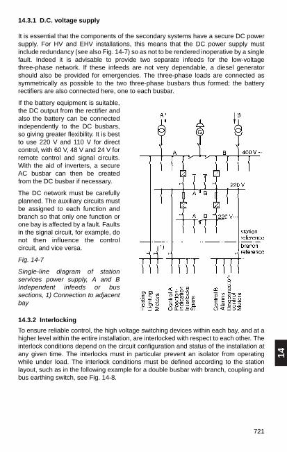
14
721
14.3.1 D.C. voltage supply
It is essential that the components of the secondary systems have a secure DC powersupply. For HV and EHV installations, this means that the DC power supply mustinclude redundancy (see also Fig. 14-7) so as not to be rendered inoperative by a singlefault. Indeed it is advisable to provide two separate infeeds for the low-voltagethree-phase network. If these infeeds are not very dependable, a diesel generatorshould also be provided for emergencies. The three-phase loads are connected assymmetrically as possible to the two three-phase busbars thus formed; the batteryrectifiers are also connected here, one to each busbar.
If the battery equipment is suitable,the DC output from the rectifier andalso the battery can be connectedindependently to the DC busbars,so giving greater flexibility. It is bestto use 220 V and 110 V for directcontrol, with 60 V, 48 V and 24 V forremote control and signal circuits.With the aid of inverters, a secureAC busbar can then be createdfrom the DC busbar if necessary.
The DC network must be carefullyplanned. The auxiliary circuits mustbe assigned to each function andbranch so that only one function orone bay is affected by a fault. Faultsin the signal circuit, for example, donot then influence the controlcircuit, and vice versa.
Fig. 14-7
Single-line diagram of stationservices power supply, A and BIndependent infeeds or bussections, 1) Connection to adjacentbay
14.3.2 Interlocking
To ensure reliable control, the high voltage switching devices within each bay, and at ahigher level within the entire installation, are interlocked with respect to each other. Theinterlock conditions depend on the circuit configuration and status of the installation atany given time. The interlocks must in particular prevent an isolator from operatingwhile under load. The interlock conditions must be defined according to the stationlayout, such as in the following example for a double busbar with branch, coupling andbus earthing switch, see Fig. 14-8.

722
Fig. 14-8
Mimic diagram of a double busbarsubstation with branch, coupling and busearthing switch
The following conditions must be satisfied in this case:
1. Disconnectors Q1, Q2 and Q9 can be operated only when breaker Q0 is open(protection against switching under load).
2. Breaker Q0 cannot be closed with disconnectors Q1, Q2 and Q9 in theintermediate position (intermediate position indication).
3. Disconnectors Q1 and Q2 are mutually interlocked so that only one can be closedat a time.
4. When the bus-tie is closed, a second bus disconnector (Q1 or Q2) belonging to thetied system can be closed. One of the two closed disconnectors can then beopened (change of bus under load).
5. Disconnectors Q1 and Q2 can be operated only if the related bus earthing switchQ15 or Q25 is open.
6. Disconnector Q9 can be operated only when earthing switch Q8 is open (takingaccount of other end if necessary).
7. Earthing switch Q8 can be operated only when disconnector Q9 is open (takingaccount of other end of outgoing line if necessary).
8. Disconnectors Q1, Q2 and Q9 can be operated only when maintenance earthingswitches Q51/Q52 are open.
9. Maintenance earthing switches Q51/Q52 can be operated only whendisconnectors Q1, Q2 and Q9 are open.
10. The tie-breaker Q0 can be opened only if not more than one bus isolator in eachbranch is closed (tie-breaker lock-in).
11. One bus earthing switch Q15 or Q25 can be operated if in the respective bussection all bus disconnectors of the corresponding bus system are open.
12. All interlocks remain active if the auxiliary power fails.
13. An interlock release switch cancels the interlock conditions. Switching operationsare then the responsibility of the person authorized.
14.3.3 Control
The purpose of a control device in a switchgear installation is to change a definedactual condition into a specified desired condition.
The operating sequences of controlling, interlocking and signalling can be performedeither by simple contact-type electromechanical and electromagnetic devices such asdiscrepancy switches, auxiliary contactors and auxiliary relays or by contact-lesselectronic components. Both methods allow single switching operations andprogrammed switching sequences up to fully automated switching routines.
With conventional control techniques, there are limits to the scope for automation.These methods are becoming less popular because of the space required, theequipment’s high power consumption, wear due to constant operation, and the fixedwiring. Today they are used mainly for local control within the switching installation.

14
723
Here, the devices can be divided into those relating to:
– switching apparatus,
– branch and
– station.
The apparatus-related devices are contained in a box on the circuit-breaker or isolator.The branch-related devices are usually in a control cubicle or local relay kiosk. Station-related devices are located in central relay kiosks or in the station control building.
Because of the increasing reliability of electronic components, and also the question ofinterference, the tendency is for contact-type systems to be employed only forapparatus-related devices, and electronic components to be used very extensively forbranch-related and station-related devices.
When drawing up the control system concept, it must be considered whether thesubstation is to be largely manned or unmanned, or remotely monitored and controlled.The kinds of control system can be broadly defined as follows.
Local control
Here, the controls are close to the switchgear. They are used mainly duringcommissioning and maintenance, often for emergencies as well. They are located onthe apparatus itself or in a branch cubicle, and work independently of higher-levelcontrol systems.
Direct control
In this case, the switchgear is controlled locally from the on-site control point, whereeach piece of apparatus has its own control switch, etc. It may utilize the switchgear’scontrol voltage or light-duty relays. Control from the station panel always includesindication of the switchgear’s respective operating positions.
Selective control
This method is used both for on-site control and in central control rooms. It is arrangedin a number of levels, so that from an operator’s position one can, for instance, pick firstthe station, then the branch and finally the item of switchgear before initiating the actualswitching operation with the "execute" button.
Both station-level and central control systems nowadays have two mutually interlockedoperator positions for this purpose. Each consists of a control panel and a VDU. Theinterlock prevents commands being sent simultaneously from both positions to a stationor branch. Certain control sequences can be pre-programmed where necessary. Lightcurrent is used for the control circuits. Feedback signals and switchgear settings areshown on the monitor. A mosaic-type display panel is sometimes provided in additionto the video screen.

724
14.3.4 Indication
Operating personnel must be informed of faults, circuit conditions and the settings ofswitchgear.
Switchgear contact settings are indicated by means of position transmitters, light-emitting diodes or on a screen. The signal must not be sent until the apparatus hasreached or is certain to reach its final CLOSED or OPEN position; otherwise anintermediate position must be indicated.
Incoming fault and status signals are indicated by optical and acoustic means, andoften recorded, see Section 14.3.8 Recording and logging. The signals are gathered orpassed on by signalling relays with floating auxiliary contacts. The relays can beelectromechanical or electronic. Table 14-3 shows the standard signal sequence ofdrop indicator relays and light indicators.
Remote control
In this case, the substation is controlled from regional and central control centres,predominantly via telecontrol lines. The general trend is increasingly away from localcontrol to remote control, so the latter warrants particular attention. For details ontelecontrol, see Sections 14.5.4 and 14.5.6.
Control functions include a wide variety of different applications; representativeexamples are the monitoring of tripping circuits, Fig. 14-9, and the duplication of trippingcircuits, Fig. 14-10.
Fig. 14-9 Fig. 14-10
Tripping circuit supervision for a circuit- Duplication of tripping circuits with breaker in closed and open position 1¹⁄₂- and 2-breaker arrangement
MonitoringIndication
Trip contactBattery
BB1
Protection
to BB2Tripping circuit1 L+
1 L–
CB auxillaryswitches
Trip collDCV 1DCV 2
TRIP 1 TRIP 2Q01
TRIP 1 TRIP 2Q02
TC
S-r
elay
TCS =tripping circuitsupervision
+
–
Q01 T1 Q02T2
T5
1 2
21

14
725
Table 14-1
Standard signal sequence for drop indicators and light indicators
Signal sequence Drop indicator Light indicator Alarm contact
Initial status
Alarm contactcloses
Acousticsignal reset
Optical signal reset a) Alarm condition
persistsb) Alarm condition
cleared
Lamp test
Lamp is out Acoustic signal
is on on
flashes off
14.3.5 Measurement
Operating a substation involves measuring, recording and evaluating a number ofquantities such as currents, voltages, powers, etc. To do this, the primary systemrequires current and voltage transformers, which can be incorporated in the busbars orbranches. What instrument transformers are necessary will depend on operatingrequirements, see Sections 10.5.2 to 10.5.5 on transformer selection.
Voltage transformers are useful in the branches for measurement and protection.Voltage transformers on the busbar as well are convenient for synchronizing andmeasurement purposes; there is then no need for simulation.
The secondary sides of current and voltage transformers must be earthed so as toavoid any risk to equipment and personnel from unacceptably high voltages.
Current transformers must not be operated with open secondary windings as the highvoltages occurring at the secondary terminals are dangerous and may damage thetransformer.

726
Current transformer circuits must be earthed at only one point. In high-voltageinstallations, this should be the branch control cubicle wherever possible. Thestandards applicable at the particular location must be observed. One must make surethat the transformer power rating is at least equal to the power consumption of themeasuring devices, including the connecting lines. The dimensions of these can bedetermined with the aid of Fig. 14-11.
Example:
A = 2.5 mm2,lr = 85 m:then R ≈ 0.6 Ω
I = 5 A, R ≈ 0.6 Ω:then S ≈ 15 VA
Fig. 14-11
Current transformer secondary lines; To determine resistance and power consumption,R = line resistance Ω, lr = resultant line length m, S = power VA, A = line cross section mm2 for Cu and Al, I = sec. transformer current A
The readings of the measurements are displayed in the control cubicles, in the on-sitecontrol room and /or at the command centre. Attention must be paid to the positioningof the instruments. With modern control systems, the readings are shown on the screenin the central control room.
The shapes, sizes and coding of switchboard instruments are summarized in Fig.14-12.See DIN 43700 and 43701 for detailed information on standardized designs anddimensions of control panel instrumentation and measurement ranges.

14
727
Fig. 14-12
a) Shapes, sizes, b) Scales and c) Coding of switchboard instruments (dimensions inmm):
A Quadrant scale, B Circular scale, C Sector scale, D Sector scale for tubularinstruments, E Linear scale; Example of coding: c) Instrument for 3-ph. 50 Hz with 2 iron-cored el.-dyn. elements Cl. 1.5; vert. posn.; test voltage 2 kV, transf. connection:prim. current 50 A, sec. current 5 A, prim. volt. 1000 V, sec. volt. 100 V
Measuring elements and their principal applications
Electrical measuring instruments have a class coding. The classes are: 0.1; 0.2; 0.5; 1;1.5; 2.5 and 5. These denote the measurement or reading error in percent, bothpositive and negative. They always relate to the top of the measuring range.Instruments of classes 0.1 to 0.5 are precision instruments, those above are industrialinstruments.
The choice of measuring elements for the instruments is summarized in Table 14-2.
DIN EN 61010-1 (VDE 0411 Part 1), DIN EN 61010-1/A2 (VDE 0411 Part 1/A1) andDIN EN 60051; plus DIN 43781 (for recorders) are applicable for electricalinstrumentation and recorders. These standards contain the most important definitions,classifications, safety and test requirements and forms of identification.

728 Table 14-2
Measuring elements for measuring instruments
Element Symbol Operating principle Input Application and characteristics
For DC and AC currents and voltages. Greater overload capacity than othermeasuring elements. Much higher consumption than moving-coil elements.Scale almost linear, but can be extensively influenced. Robust.
Chiefly a DC instrument. Together with rectifiers also suitable for AC; withadapters also for power measurement. Greater accuracy than all other electrical measuring elements. Lowconsumption. Scale almost linear. Moving-coil galvanometers are highlysensitive.1)
For power measurement with AC and DC, as quotient meter also formeasuring power factor. Scale almost linear. Largely independent offrequency and curve shape. Core-less types for precision instruments, iron-cored types for industrial instruments and recorders.
For DC and AC voltages, also high-frequency voltage.
For frequencies from 7 – 1500 Hz.High, consistent measuring accuracy. Robust.
For monitoring thermal loading of transformers and power cables. Withresettable slave pointer. Scales calibrated in percent or amps.Compensated for changes in room temperature.
Moving-ironelement
Moving-coilelement
Moving-ironratiometer(cross-coil element)
Electro-dynamicelement
Electronicelement
Vibrating-reed element(reed-typefrequencymeter)
Bimetal element
Two iron cores in a ring coil aremagnetized with the same polarityand repel each other.
Coils able to rotate in thehomogeneous field of a permanentmagnet; variants with magnet outsideor as core magnet element withpermanent magnet inside the coil.
A voltage coil is able to rotate in thehomogeneous magnetic field of afixed current winding.
Two electrodes in an electrostaticfield move relative to each otherowing to potential differences.
A row of steel reeds is induced tovibrate in the force field of anelectromagnet.
A bimetal spiral indicates the meanvalue of prolonged loads.
l –, U –I ~, U ~
l –, U –Thermocouple,Resistancethermometer,I ~, U ~Active power,Reactive power,Power factor
Active power,Reactive power,Power factor
U –U ~
Frequency
I ~
1) Sensitivity and accuracy must not be confused. If an indicating instrument is required to be sensitive, this means it has to respond to small changes in the measuringvariable with large scale deflections, but it does not have to be accurate.

14
729
Measuring transducers
Transducers in the field of power engineering convert input variables such as current,voltage, power and system frequency into analogue electrical output quantities, usuallyin the form of impressed direct current but sometimes also impressed d.c. voltage.These output quantities are then particularly suitable for subsequent measured-valueprocessing and transmission systems.
The most important parameters, device properties, designations and tests oftransducers for quantities in electrical engineering can be found in the VDE 0411 Part 1and VDE 0411 Part 1/A1 standards mentioned above in the “Instrumentation” section.The DIN EN 50178 (VDE 0160) and the VDE/VDI Directive 2192 must also beobserved.
Fig. 14-13 shows various measuring arrangements. The transducers can be single ormultiple. Table 14-3 shows an overview of the typical consumption values of the mostimportant instrumentation.
Fig. 14-13
Common measuring circuits with transducers:
a) Connection to indicating and recording instruments in the transducer output circuitfor indoor stations, b) Connection to selectable instruments via shunt resistors in thetransducer output circuit for outdoor stations, AZ Indicating instrument, EDP Dataprocessing, FWA Telecontrol system, I Current, MU Transducer, NW Shunt resistor, S Recorder, SM Signal meter with maximum contact, U Voltage, Z Zener diode
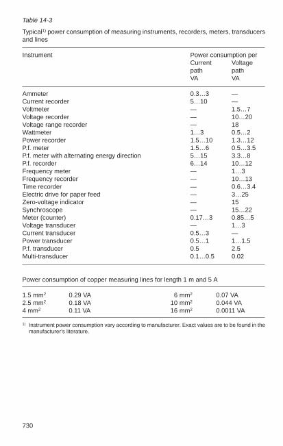
730
Table 14-3
Typical1) power consumption of measuring instruments, recorders, meters, transducersand lines
Instrument Power consumption perCurrent Voltagepath pathVA VA
Ammeter 0.3…3 —Current recorder 5…10 —Voltmeter — 1.5…7Voltage recorder — 10…20Voltage range recorder — 18Wattmeter 1…3 0.5…2Power recorder 1.5…10 1.3…12P.f. meter 1.5…6 0.5…3.5P.f. meter with alternating energy direction 5…15 3.3…8P.f. recorder 6…14 10…12Frequency meter — 1…3Frequency recorder — 10…13Time recorder — 0.6…3.4Electric drive for paper feed — 3…25Zero-voltage indicator — 15Synchroscope — 15…22Meter (counter) 0.17…3 0.85…5Voltage transducer — 1…3Current transducer 0.5…3 —Power transducer 0.5…1 1…1.5P.f. transducer 0.5 2.5Multi-transducer 0.1…0.5 0.02
Power consumption of copper measuring lines for length 1 m and 5 A
1.5 mm2 0.29 VA 6 mm2 0.07 VA2.5 mm2 0.18 VA 10 mm2 0.044 VA4 mm2 0.11 VA 16 mm2 0.0011 VA
1) Instrument power consumption vary according to manufacturer. Exact values are to be found in themanufacturer’s literature.

14
731
14.3.6 Synchronizing
Synchronizing is also a kind of measurement. System components cannot beconnected in parallel unless their voltage curves coincide, otherwise the electricalstresses on the equipment become too high. While with direct current it is sufficient forthe system components’ voltage and polarity to be the same, with a.c. voltages thefrequency, voltage and phase angle must match; with three-phase current so must thephase sequence.
The standard synchronizing instruments are double frequency meter, double voltmeterand synchronoscope. Digital control technology now offers the option of feeding theinput signals of these instruments directly to an automatic synchronization device,which independently trips the closing operation at the right time.
When parallel switching system parts, it is sufficient to use an automaticsynchronization test instrument, e.g. the Synchrocheck design of the SYNCHROTACTrange from ABB, which prevents switching in asynchronous mode with non-permittedhigh phase difference angles or excessively high voltage differences.
Fig. 14-14
Automatic synchronization test instrumentWhen paralleling conditions have been met,the contact is closed, the networks can besynchronized.
N etz 1
N etz 2
-+
S Y N C H R O TA C T
Fig. 14-15
Automatic synchronizer unitThe synchronizer device issues higher andlower commands to turbine controllers andvoltage controllers. When parallelingconditions are met, the circuit-breaker isclosed at the exact moment when the phasesare the same.
N etz
G
E rregungf+ /f-
U + /U -
-+
S97022
S Y N C H R O TA C T
U N ITR O L
An automatic synchronization device is always recommended for parallel switching ofgenerators with power supply units. This automatically brings the speed and voltage ofthe generator into a preset tolerance range using higher and lower commands. Thevoltage, phase angle, frequency and switch mechanical delay are taken into account toset the paralleling command to ensure that the switch contacts touch at precisely theinstant the phases are the same.
Net 1
Net 2
Net
Excitation

732
The SYNCHROTACT automatic synchronization device in its simplest form is onesingle channel, which takes care of measurement, voltage, frequency balancing,monitoring and command formation with high security against faulty operation.Depending on system size and safety design, dual channel solutions are also available.Measuring, microprocessor and command relays in both channels are separate in theSYNCHROTACT dual-channel synchronization units. This independence significantlyincreases security against faulty operation in comparison to the single channel system.
14.3.7 Metering
General
Meters are used for determining the amounts of power supplied from the power sourceor distribution system to the consumer. The selection criteria are shown in Table 14-4.
In a special category are meters for billing electricity consumption. In the FederalRepublic of Germany, for instance, they have to meet the requirements of thePhysikalisch-Technische Bundesanstalt (PTB) and of the Deutsches Amt für Maße undGewichte (DAMG), i.e. certified and approved. The voltage drop on the instrumenttransformer line of billing meters must not exceed 0.05 %.
Table 14-4
Selection criteria and alternatives for electricity meters (counters)
Criterion Alternatives
Connection direct or to instrument transformerType electromechanical or electronicMounting surface-mounted housing, live parts fixed
flush-mounted housing, live parts fixedflush-mounted housing, live parts removablesubrack, live parts on circuit boards
Current alternating currentthree-phase in 3- and 4-wire systems loadedsymmetrically and asymmetrically
Power active and reactive consumption, incoming andoutgoing1)
Tariff single or two-rate tariff2)
Accuracy class 0.2, 0.5, 1, 2, 3Metering system primary system3)
semi-primary system4)
secondary system5)
Special meters maximum-demand meters6)
pulse meters7)
remote meters1) Reversal prevention is necessary where the power flow direction changes. 2) Tariff changed with separate timer or ripple control receiver. 3) The ratio of preceding transformers is accounted for in the meter reading. 4) This takes account only of the ratio of preceding voltage or instrument transformers, the readings
must be multiplied by a constant. 5) This does not take account of the ratio of preceding transformers, the readings must be multiplied
by a constant. 6) The maximum rate is calculated from the price per kilowatt-hour (kWh) and per kilowatt (kW). 7) These measure the power throughput and according to the units counted, emit pulses to the
connected remote meters, remote summation meters or telecontrol devices.

746
14.4 Substation control with microprocessors
14.4.1 Outline
Substation control facilities using microprocessors and serial data transfer perform allthe established functions of the secondary systems in transformer and substations, i.e.on / off control, interlocking, measurement, feedback control, indication, signalling,protection (feeders and busbar) and metering etc..
But computer-aided systems offer more: process diagnostics, the creation andautomation of decentralized substations, together with preliminary on-site dataprocessing, so easing the general task of network management.
A radical feature of this new technology is its diagnostic capability, which alone hasoperational benefits for the user, even if he decides against the other new possibilitiesavailable.
Overall, the new technology offers
– fast fault recognition – simple system structure – error-free operation,
so significantly improving station availability.
14.4.2 Microprocessor and conventional secondary systems compared
With conventional secondary systems, the various functions considered in Section 14.3are performed by separate devices (discrete components) which mostly work on theanalogue principle and as a rule are of varying sophistication.
The resulting situation is as follows:
– Each task is performed by devices employing different technologies(electromechanical, electronic, solid-state or microprocessor-based).
– These discrete devices may require many different auxiliary voltages and powersupply concepts.
– The links between the devices and with the switchgear require a great deal of wiringor cabling and means of matching.
– The information from the switching apparatus has to be applied separately tonumerous inputs for protection, control, interlocks etc., so monitoring the interfacesis complicated.
– Checking the performance of the individual devices is accompanied by more difficultverification of overall performance.
With the new control technology for switching installations, the emphasis is on thesystem and its function as a whole.
Digital methods are employed for the respective functions, using programmablemodules based on microprocessors.
The distinguishing features of the new technology are:
– Use of identical device components or combined devices based on microprocessorsfor the various tasks or functions.
– Standardized power supply and supply concept.

14
747
– Serial data transfer minimizes wiring (bus technique).
– Fibre optic cables are used near the process to reduce the cost of establishedadequate electromagnetic compatibility.
– Composite use made of data from the switchgear.
– Self-diagnosis with continuous function check-up, hence simpler testing of overallsystem and subsystem.
– Simple correct-sequence signal acquisition with a resolution of about 1 ms.
– Reduced space requirements.
– Records of station functions.
Another major innovation of the new approach is the man-machine interface (MMI).While the access interface to conventional secondary technology is switch panel- ormimic control panel-oriented with the elements of switches, buttons, lamps andanalogue instrumentation, access to the new control systems is usually through adisplay at bay level and through monitors and keyboards at substation and systemcontrol centre level. Operation is mostly menu-guided, so no programming or computerskills are necessary.
14.4.3 Structure of computerized control systems
A substation can be divided broadly into a sector comprising the switchbays (feeders,ties, sectionalizers and earthing system) with their functions:
– Control, supervision, interlocking – Transformer control and voltage regulation – Bay-level automatic functions – Indication acquisition and processing – Measurement acquisition and processing– Local (bay) control– Autonomous bay protection
and a sector with higher-level, i. e. station-related, tasks such as:
– Local (station) control– Communication link– Connection to station auxiliaries– Station functions– Busbar protection.
The logic structure of the control system consequently has two hierarchical levels: theswitchbay level with the bay units (BU) and the station level with the station unit (SU),see Fig. 14-26.

748
Fig. 14-26
Logic structure of computerized substation control
local controllernetwork fault
analysis
centralnetwork fault
analysis
network controlcentres
control stationcoupling device
data exchange
protectioncontrol
secondaryinstallations
switchbay n
control
switchbay 1
protection
stationfunctions
busbarprotection

14
749749
On the process side of the control system, the bay units are assigned accordingly to theprocess (switchbays). The result is that between every switchbay and theassociated bay unit either a parallel connection, i.e. a direct connection betweenswitchbay and bay unit is established for every datapoint such as position indicatorsand encoders for analogue values, or the data are linked to the bay unit by actuatorsand sensors over a process bus.
The functions performed in the bay units are basically those which require data fromtheir associated switchbay (e.g. Iine protection, bay interlocks) and for which shortfunctional loops are preferable.
The functions in the station unit, on the other hand, are those which need data from thewhole station (e.g. busbar protection, priority treatment of alarms, indication of busbarvoltage) or have a central function (connection to network control centre, radio timemark receiver, central operating position).
Serial links are used throughout for transferring data between bay and station units.The serial links are arranged radially. With a radial configuration serial links passradially from the station unit to all bay units, and via these links the station unit canexchange data simultaneously with the bay units.
The ABB PYRAMID substation automation system uses a bus system for this datatransmission. The radial (star) network consists of fibre-optic cables which are broughttogether at a star coupler (see also Section 14.4.4).
The bay and substation units are built up from modular components, or as a combinedbay control and protection unit. The number of modules used depends on the requiredquantity of functions, the desired structure and specified aspects of system quality,such as availability. However, for safety reasons, in the high-voltage area beyond 72 kVthe protection components are generally designed to operate independently of theother components of that bay unit.
Components of this new technology are also used for the self-contained protectioncircuits prevalent today, which provide additional information such as fault recordingand fault location.
The self-contained protection devices can be of traditional or digital design, even fromdifferent manufacturers or different generations of protection equipment. In the case ofconventional protection gear, parallel wiring continues to be used for the signal linesbetween bay and station units. Modern digital devices, on the other hand, offer thepossibility of serial data transmission. To enable this, the interface is defined as per IEC 60 870-5-103 as a standard interface for serial connection of protection devices.Fig. 14-27 shows the general structure of the ABB PYRAMID control system with itsdecentralized function components. The star coupler ensures data communicationsbetween the autonomous subsystems.
The functions are decentralized, irrespective of the bay unit’s locations and distribution.
A recommendation on “Digital Station Control Systems” by the VDEW working groupfor “Integrated Station Control Systems” has been in force since 1994, and a revisedversion is currently in preparation.
Sections 7.2.5 and 8.2.5 contain further information on computer-aided control forlow-voltage and medium-voltage systems.
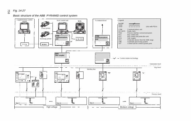
750 Fig. 14-27
Basic structure of the ABB PYRAMID control systemSupplementary control
station
Event printer
Hardcopy printer
COMcommunicationsunit
COMcommunicationsunit
RERStar coupler
To network level
Central station technology
Substation level
Bay level
Process level
Medium voltageHigh voltage
Interbay bus
Bay zBay nBay mBay 1
Protection
Legend
parallelserialserial (also with PISA)
COM Communications unitDCF/GPS Radio clockPISA Process interface sensors/actuatorsREC Bay control unitREF Bay control and protection unitRER Star couplerREx Protection device from the ABB rangeSMS Fault data processing systemZAT Control unit for central system parts
local control unit
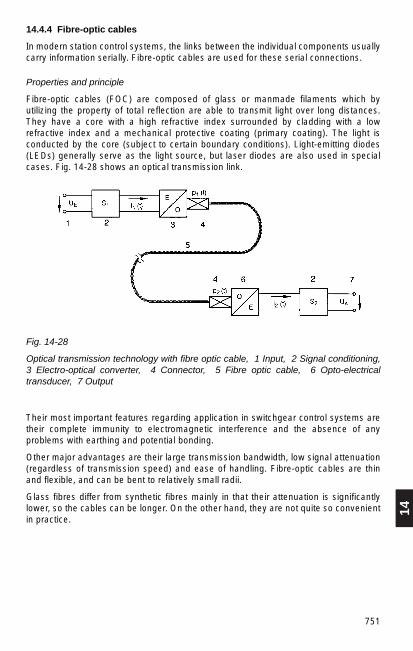
14
751
14.4.4 Fibre-optic cables
In modern station control systems, the links between the individual components usuallycarry information serially. Fibre-optic cables are used for these serial connections.
Properties and principle
Fibre-optic cables (FOC) are composed of glass or manmade filaments which byutilizing the property of total reflection are able to transmit light over long distances.They have a core with a high refractive index surrounded by cladding with a lowrefractive index and a mechanical protective coating (primary coating). The light isconducted by the core (subject to certain boundary conditions). Light-emitting diodes(LEDs) generally serve as the light source, but laser diodes are also used in specialcases. Fig. 14-28 shows an optical transmission link.
Fig. 14-28
Optical transmission technology with fibre optic cable, 1 Input, 2 Signal conditioning,3 Electro-optical converter, 4 Connector, 5 Fibre optic cable, 6 Opto-electricaltransducer, 7 Output
Their most important features regarding application in switchgear control systems aretheir complete immunity to electromagnetic interference and the absence of anyproblems with earthing and potential bonding.
Other major advantages are their large transmission bandwidth, low signal attenuation(regardless of transmission speed) and ease of handling. Fibre-optic cables are thinand flexible, and can be bent to relatively small radii.
Glass fibres differ from synthetic fibres mainly in that their attenuation is significantlylower, so the cables can be longer. On the other hand, they are not quite so convenientin practice.
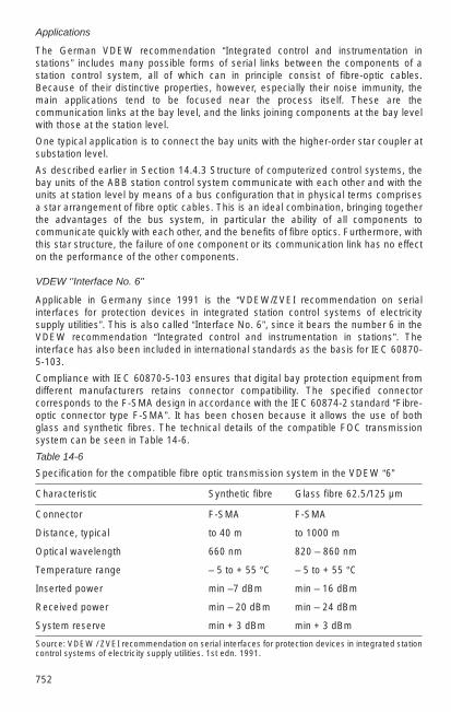
752
Applications
The German VDEW recommendation “Integrated control and instrumentation instations” includes many possible forms of serial links between the components of astation control system, all of which can in principle consist of fibre-optic cables.Because of their distinctive properties, however, especially their noise immunity, themain applications tend to be focused near the process itself. These are thecommunication links at the bay level, and the links joining components at the bay levelwith those at the station level.
One typical application is to connect the bay units with the higher-order star coupler atsubstation level.
As described earlier in Section 14.4.3 Structure of computerized control systems, thebay units of the ABB station control system communicate with each other and with theunits at station level by means of a bus configuration that in physical terms comprisesa star arrangement of fibre optic cables. This is an ideal combination, bringing togetherthe advantages of the bus system, in particular the ability of all components tocommunicate quickly with each other, and the benefits of fibre optics. Furthermore, withthis star structure, the failure of one component or its communication link has no effecton the performance of the other components.
VDEW ‘’Interface No. 6"
Applicable in Germany since 1991 is the “VDEW/ZVEI recommendation on serialinterfaces for protection devices in integrated station control systems of electricitysupply utilities”. This is also called “Interface No. 6”, since it bears the number 6 in theVDEW recommendation “Integrated control and instrumentation in stations”. Theinterface has also been included in international standards as the basis for IEC 60870-5-103.
Compliance with IEC 60870-5-103 ensures that digital bay protection equipment fromdifferent manufacturers retains connector compatibility. The specified connector corresponds to the F-SMA design in accordance with the IEC 60874-2 standard “Fibre-optic connector type F-SMA”. It has been chosen because it allows the use of bothglass and synthetic fibres. The technical details of the compatible FOC transmissionsystem can be seen in Table 14-6.
Table 14-6
Specification for the compatible fibre optic transmission system in the VDEW “6”
Characteristic Synthetic fibre Glass fibre 62.5/125 µm
Connector F-SMA F-SMA
Distance, typical to 40 m to 1000 m
Optical wavelength 660 nm 820 – 860 nm
Temperature range – 5 to + 55 °C – 5 to + 55 °C
Inserted power min –7 dBm min – 16 dBm
Received power min – 20 dBm min – 24 dBm
System reserve min + 3 dBm min + 3 dBm
Source: VDEW / ZVEI recommendation on serial interfaces for protection devices in integrated stationcontrol systems of electricity supply utilities. 1st edn. 1991.

14
753
14.5 Network control and telecontrol
14.5.1 Functions of network control systems
The purpose of network control systems is to operate transmission and distributionnetworks economically and reliably with the aid of data processing and informationtechnology. The principal aim under normal conditions is to minimize overheads andcapital costs by optimizing the utilization of the equipment, and under fault conditions tosecure the supply of power at all points of the network and restore the situation tonormal with interruption times kept to a minimum.
In order to achieve this, the status of the (usually extensive and closely intermeshed)network as regards topology, voltage and load must be known at all times, abnormalvalues must be instantly detected and signaled, and countermeasures taken. As supplysystems become ever more complex, this is done at control centres which are fed byway of telecontrol links with all the information from the switchgear necessary forappraising the network’s status and controlling it.
Initially, all functions were centralized in the control station. However, the increasingvolume of information soon resulted in a shortage of processing capacity. The currenttrend is to decentralize most individual tasks at the point where they occur byimplementing intelligent telecontrol stations or more powerful substation automationsystems and to forward only the compressed information essential for centralizedcontrol of the overall network to the central control station for processing.
The exact duties to be performed by the network management system depend on thetype and size of the network, on the nature of its main equipment and on the operationalstrategy adopted by the network operator.
In the supraregional network, the electricity is transported in bulk from the powerstations to the load centres at voltages of 380 kV and 220 kV, or sometimes higher. Thistransmission network in turn supplies the distribution systems, operating at 110 kV, 60 kV, 20 kV, 10 kV and also other voltages, which carry the electricity at regional levelfrom the interconnected network to the consumers.
The entire control and supervision of the machinery and equipment in the power plantitself, such as turbines and generators, is the province of power plant control, and so isnot considered further here.
The tasks of network control begin with transmission of the electricity. For this, aload-dispatching centre controls the output of the power stations and the flow of powerin the grid to meet the demand at any moment, aided by equivalent load curves fromprevious periods and according to mutual agreements with other electrical utilities,supplying the grid and large customers, together with various other parameters, inorder to provide the most economical and secure service.
Network control centres monitor and control circuit status and the loading on switchgearand lines in the bulk transmission and distribution systems. When faults occur, it ispossible with the aid of the high-speed data processing to obtain immediately anup-to-date picture of the network’s general status and the situation at the site of thefault, then select and execute the required switching operations.

754
At the urban and municipal level, the supply of all forms of energy, i.e. gas, water,district heat, etc. as well as electricity, is controlled from one central multi-purposecentre.
The exact performance required from such a management system determines theequipment in the control centre. Today this consists almost exclusively of computersystems with separately assigned functions, together with colour monitors fordisplaylng the network and its parts. Because of the continuous increase in the scopeand interconnection of the information processed in the control stations, it would nolonger be possible for the control room staff to monitor and control the system withoutthe aid of information technology. Process computers take over routine tasks fromoperators and quickly and safely prepare the data for processing. Central control roomswith computers and colour monitors for standard control operation and with anadditional mimic diagram or large display with cumulative information for emergencyoperation or geographical overview are also encountered.
The internal data processing and information systems in many utilities are nownetworked with company data networks. This offers the option of deriving informationfrom the system control technology for planning tasks, e.g. for network andmaintenance planning, and for management information.
Practical experience shows that the designing of a new network management systemcalls for close cooperation between operator and supplier so that the individual parts ofthe system, such as data acquisition, transmission and processing, can be ideallymatched to each other and to what they are required to do.
The general concept is often arrived at with the aid of joint preliminary studies, includingthe use of simulators, in order to make full use of today’s technology and optimize thecontrol system to the specific requirements.
The Federation of German Electricity Companies VDEW has published a manual ofrecommendations1) on the design, construction and operation of network controlcentres, telecontrol and process computer systems, ripple-control systems, controlrooms, auxiliary services, station control and network management. The differentsubjects are thoroughly dealt with in separate volumes.
These are:0. General (overview, project management, non-technical requirements, awarding
contracts)
1. Telecontrol systems (general, functions, technical requirements)
2. Ripple-control systems (basic planning, frequency planning, interactions, ripple-control receivers)
3. Process computer systems (task division in control and subcontrol rooms, functions,design of process computing systems, network database, interfaces)
4. Control engineering (task division and analysis, information input and output, controldesign, control room, ergonomic requirements)
5. Auxiliary equipment (backup power supply, rooms, signalling equipment,communications, equipment protection)
6. Integrated control systems in substations (design, requirements, information for theoperator)
1) Manual “Netzleitsysteme in Elektrizitätsversorgungsunternehmen (EVU) – Empfehlungen”(Network control systems in electrical utilities – Recommendations), VDEW-Verlag, 4/1994

14
755
7. NN
8. Network control systems
9. Standards, directives and recommendations
The latest supplement to this publication appeared in April 1994 as a ring binder. Somedesigns have in the meantime been superseded by technical progress. However,additional revisions are not proposed at present because the publisher is planning toreplace the publication by various internationally coordinated documents.
The international standard on process data communication in network control systemsis IEC/TC 57 “Power system control and associated communications”. The K 952“System control technology” of the DKE is the responsible technical committee forGermany.
The results of the standardization are published internationally as parts of the IEC60870 publication “Telecontrol equipment and systems”. In Europe, the publications areappearing from IEC 60870 as EN 60870 with the corresponding part number of the IECdocument, in Germany as DIN EN 60870.
14.5.2 Control centres with process computers for central network management
With the growing trend towards centralized management of power networks and theaccompanying large volume of incoming information, operating staff were subjected toan ever heavier work load until eventually they were unable to cope even under normalconditions owing to the limits on their ability to assimilate data within a given time span.In the interests of clarity and security, the information therefore has to be conditionedand condensed. The operators must be relieved of routine duties so as to be free forimportant tasks and decisions.
These demands can be met only by using programmable process computers. Table14-7 lists a number of tasks that can be performed with the aid of process computers innetwork control centres and outstations. Although the technology has made rapidprogress since this part of the recommendation (1981) was published and newsolutions such as the integrated control system in the outstations have beenimplemented, in principle the task assignments are still generally current.

756
Table 14-7
Tasks for process computers in control centres and substations1)
1 2 3
Display and supervision Control of switchgear Load managementof network status and auxiliaries
1) Summary from manual "Netzleitsysteme in Elektrizitätsversorgungsunternehmen (EVU) –Empfehlungen" (Network control systems in electrical utilities – Recommendations), Section 3.1,4/81
(continued)
Alphanumeric display ofincoming data tabulated in clear text – group signals – derived single signals
Graphic display of network andstation diagrams – networks by voltage level – subnets – block diagrams of
transformer and substations – station segments – station allocation lists – list of available pictures
Additional information inselected pictures – measurements (digital or bar
diag.) – setpoints and limit values – updates of switchgear
settings– identification of earthed and
unavailable apparatus– identification of messages to
be reset locally– indication of work in progress
on switchgear
Use of colour display units– separate colour per voltage
level or network sectionhaving same earthingcondition
Mimic panel as general display– geographical layout– linked node-point signals– limited additional information
Command input via keyboards– all kinds of control command– uniform operation– independent of existing
control systems
Multiple-step commands– operator guidance functions– stepwise checking of
completeness and correctsequence
– command output, storageand reporting
System load measurementand monitoring – measurement of energy
at supply points – transmission as meter
reading or pulse string – acquisition and storage in
computer – calculation of total
system load overaccounting period
– determination of freecapacity
– generation of substitutevalues for missing values
– output via VDU or digitaldisplay
– printouts of individualvalues
Load management– calculation of load trends– short-range load
forecasts– time-related load control
Operation of ripple-controlsystems – manual commands to
control unit, bypassingcomputer
– manual commandsthrough computer
– automatic commandsthrough computer basedon calculation

14
757
Table 14-7 (continued)
Tasks for process computers in control centres and substations1)
4 5
Load shedding Documentation of events –printouts and off-line storage
Determination of loads todisconnect according to– time of year– day of week– time of day– system load immediately
before fault– available generating capacity– network circuit status
High-speed detection of faultcriteria and measurements– system frequency– unassisted power available– total system load– load of separately switchable
subnets– measurements to determine
transfer lines
Shedding of load– determination of optimum
reduction with computer– disconnection with minimum
delay– assumption of load frequency
control in subnet
(continued)
Printouts required for – recording events in network – later analysis of disturbances – statistical purposes – future planning
Clear text printouts– text summaries– clearly organized typefaces
Computer tasks – essential information in most
effective form – data conditioning and
compression – collation of data – production of sorted reports
Off-line storage required for – examination and analysis of
past events or operatingconditions
– network planning – forecasting
Selection of storage media – disk– tape, cassette – punched tape, cards– diskette, CD-ROM
Preparation for storage – conversion to most suitable
form – savings of memory space
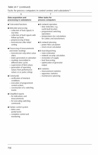
758
Table 14-7 (continued)
Tasks for process computers in control centres and substations1)
6 7
Data acquisition and Other tasks forprocessing in substations process computers
Telecontrol functions
Indication processing– collection of fault signals in
real time– collection of fault signals with
follow-up faults– preprocessing of data– transmission after initial
sorting
Processing of measurementsand meter readings – transmission only when value
alters – totals generated at substation – readings transmitted in
different time cycles – supervision of limit values – generation of operating
values from performancevalues or as pulse strings
Commands– verification of interlock
conditions– execution of programmed
control actions– construction of a switching
matrix
Simplified reports– for indications and
measurements– for executing switching
commands
Station control system– takes over
partial tasks– complete control and
monitoring
In network operation – data reduction, e.g.
earth-fault location – programmed switching
operations – temperature-rise calculations
for cables and transformers
In network planning– power flow calculation– short-circuit calculation
In load dispatching– state estimation– network security calculation– restoration of supply– load forecasting– optimization of generator
output
In statistics– measurement statistics– apparatus statistics– maintenance planning

14
759
Which of the many functions are to be incorporated in a control centre depends verymuch on the performance specification and financial resources at the user’s disposal.Deciding the exact details must form part of the planning phase.
PC-based computer systems with fully graphic colour monitors for process control areprimarily used in small and medium municipal and regional control stations, and also instation control systems. In selecting computers, great emphasis is placed oncommercially available industry standards for the hardware, the operating systems andthe basic software (e.g. OS/2, RMX, Windows). Networking over local area networks(LAN, Ethernet) is also important.
In addition to straight electricity control rooms for medium-voltage networks, sometimeslinked to load management, this category also includes multi-purpose centres forseveral different types of energy, e.g. electricity, gas, district heat and water, which runin parallel on the same or multiple networked computer systems and are monitoredfrom the same workstation.
Very exacting demands are made on the computer systems for large and complexnetwork management facilities and for load-dispatching centres. In addition to standardsystem control (SCADA basic functions), more advanced tasks for network operation,load distribution, system planning and for statistical purposes must be handled here.These functions are designated as higher decision and optimization functions (HEO) oras energy management functions (EMS).
The computer hardware used consists of 32-bit computers, increasingly also 64-bitcomputers, with the associated storage media, teletypes, printers, graphic monitors,keyboards, etc. Front-end computers or remote terminals are used to link localsubstations and telecontrol lines
Multiple computer configurations with redundancy are used in medium and largernetwork management systems in order to increase availability and spread the workload. With the hierarchical system structure which used to be customary, computersconnected in series performed different tasks such as time-critical scheduling oftelecontrol lines, network management and statistical calculations. If a computer wentout, others connected in parallel took over operation without interruption and with noloss of data. Now “distributed computer systems” are primarily used for this purpose.The overall system tasks are distributed over smaller computer units, which areconnected in parallel to a duplicate or segmented LAN (Local Area Network) and canalso operate independently of one another.
Besides the hardware, the network management system’s capabilities are determinedabove all by the software. Preferred operating systems are the widespread and provenstandards, e.g. UNIX operating systems such as ULTRIX, POSIX, HP-UX, or theindustry standard operating system OSF/1. An important requirement of the applicationsoftware, apart from performing all its allotted functions, is that it should be easy to use.The user must be able to manage the system without any programming skills, and withdialogue guidance easily be capable of adjustments and changes to the data andnetwork configurations.
Control centres equipped with process computers require a number of other facilities aswell. Besides air-conditioning for the computer rooms to maintain a constantatmosphere, an uninterruptible power supply is necessary to prevent data from beinggarbled or lost.

760
Chapter 3 of the VDEW manual “Netzleitsysteme in Elektrizitätsversorgungs-unternehmen (EVU)” (Network control systems in electrical utilities) contains a series ofrecommendations for task allocation and design of process computer systems incontrol stations and outstations. An important part of this chapter is also the “processfor development of a network database”.
ABB provides an integrated series of network control systems for economical andreliable management of power supply networks with the S.P.I.D.E.R. system familyunder the Panorama integrated system solution to cover all task areas from thesmallest introductory version to the largest load distributor.
The S.P.I.D.E.R. MicroSCADA system, a PC-based control system, is designed forsmall and medium tasks in system control and also for load management and stationcontrol systems. The S.P.I.D.E.R. SCADA system is the basis for larger network controlsystems. Depending on the actual application, it can be scaled up for high-performancenetwork control systems, e.g. for higher optimization tasks to the S.P.I.D.E.R. EMSsystem, as a distributor network management system to S.P.I.D.E.R. DMS or in pipelinemonitoring to S.P.I.D.E.R. PMS. All these systems are equipped with high-performancecomputers of the DEC-VAX family.
The hardware and software of all S.P.I.D.E.R. systems are made up of self-containedmodules which are compatible with each other and can easily be combined to formcomplex, distributed network management systems. In addition, S.P.I.D.E.R. networkcontrol systems are completely separate from the switchgear itself and the telecontrolfacilities. They can be adapted without difficulty to any set of requirements.
14.5.3 Control centres, design and equipment
The aim of control room design is to create the best possible man-machine interface(MMI). All the facilities must be provided for controlling and supervising technicalprocesses and equipment from a central point located at a distance from the variousinstallations.
The essential requirements to be met by a control room are a clear presentation of thesupervised network or network segment, indication of the circuit conditions, voltagesand loadings of the apparatus and linking conductors, the immediate and unambiguoussignalling of abnormal circumstances and the keeping of records regularly and inresponse to events.
To arrive at the best possible solution for performing all the control and supervisorytasks, many different aspects have to be considered in equipping and arranging thecontrol room. Included among these is the field of ergonomics, which is the scientificstudy of optimizing and standardizing the communication interface between man andprocess to accord with human cognitive capabilities and reactions.
An important point when designing a control room is that the equipment must be suitedto its particular task, and must also take into account the limited capacity of a person toabsorb information within a given length of time. All important information must bepresented within the operator’s primary field of view. Here, attention must be paid to thecorrect arrangement of the individual functional units, such as VDU, operator’s consoleand signal display, and also to an appropriate and easily understood representation ofthe state of the system and the various controls.

14
761
These technical considerations have also given rise to recommendations on the controlroom’s interior design. These aim to create physiological comfort by means ofglare-free lighting, acoustic treatment and indoor climate, but at the same time makesure that the operating staff stay alert. Although their duties are not very demandingunder normal circumstances, they must react quickly and correctly if trouble occurs.The relevant DIN, EN and IEC provisions must be observed with respect to theseenvironmental conditions.
Further recommendations and hints on control room design are to be found in theVDEW manual “Netzleitsysteme in Elektrizitätsversorgungsunternehmen (EVU)”(Network control systems in electrical utilities). Volume 4 “Control room design” (as of08/92) contains guidelines on all major aspects of planning and designing networkcontrol centres, including the essential considerations of – human physiology and sensory perception, – codification of information (e.g. as symbols), – presentation and interrelation of information, taking into account disturbing
influences such as glare, noise, etc.
The individual subsections describe the general task allocation of the controlengineering, the task analysis including task assignment and functional overview forthe specific application case, provide details of input of information (commands, controland display) and information output (information quantities, processing and display),provide suggestions for control procedures, on the spatial configuration of thesubsystems inside the control room, on control room equipment and air-conditioningand also on the ergonomic requirements. At the end, a series of provisions anddirectives that must be considered in control engineering is listed.
As the control room is often seen as reflecting the image of the supply utility, this isanother significant aspect to be considered in deciding the furnishings and fittings.
Up to the seventies, a large mimic panel was the principal and often also the onlymeans of displaying a replica of the network. Owing to increasing centralization andautomation together with the growing complexity of power supply systems, themosaic-type mimic panel has lost its former importance. It certainly provides a quickoverall view of the network, but limits are imposed by sheer size and the ease ofrecognizing details. The mosaic-type mimic panel has hence become restricted to localor other small control rooms where system layout and status can still be shown usingsimple systems on a manageable area and modifications to network configuration andapparatus can be made without difficulty. The mosaic panel with reset controlscontinues to be used as well as VDUs in larger control centres, serving to provide a lessdetailed overall picture, a stylized map of the network, and also back-up for the mainsystem. More and more often batteries of projectors are found in control rooms, whichare arranged in a pattern and project a seamless overview of the entire system in onelarge image. The active network images are taken from the computer, and videoimages (e.g. door monitoring) can also be incorporated into the general view. Inaddition to the usual means of signalling and control, the panels are also fitted withother intelligent devices for indicating faults, large-scale displays and recording.

762
In all medium-sized and larger control centres with process computers, the details ofthe network are shown on fully-graphic colour VDU terminals. With these, it is possibleto prepare and display the specific up-to-date information necessary for a givenswitching operation or for fault analysis. All unneeded information, such as healthybranches, can be omitted. Important details can be emphasized by colour, e.g. Iineloadings, earth lines, etc. Signals and measurements arriving spontaneously can bepresented on the screen as they occur. The video terminal thus offers a greater densityof information than the same area of a mosaic panel, and at the same time more clearly,i.e. perceived faster and more reliably by the operator. Different parts of a picture canbe shown on a number of adjacent screens. In another form of presentation, the pictureshown on one screen sweeps across the entire network (rolling map method).Additional functions offered by the graphics monitors are image zooming, declutteringwith automatic changes of the degree of detail when zooming, the windowing techniquewith temporary display of windows for control or help and softkeys (virtual keys) thatcan be shown on the edges of the display for frequently occurring functions. The imagesection and the equipment that is to be controlled during switching operations and inputof the switching command are selected on screen, primarily using keyboards on thecontrol panel as the input device but also “virtual keyboards” on the display or cursorpositioning on the screen with a joystick, arrow keys, roller ball or mouse. Light pensand digitizing tablets with stylus are not recommended because that would require themonitors to be installed within reach of the operators. However, this does enable thechange service to design images and symbols particularly quickly.
In both conventional and computerized control rooms, the process is usually controlledfrom a desk or console. It is important that the monitors used to depict and control thenetwork are simple to operate and show the network in a uniform manner, especiallywhen an extensive management system has several computers sited at various placesin the network, e.g. at the control centre and at the substation. The previously process-orientated operating staff must be able to do their work easily, without the need forskilled computer specialists. In many cases, therefore, the operator receives guidancefrom the screen in the form of a menu showing instructions on forthcoming controlactions, either in clear text or by means of icons, in much the same way as with modernpersonal computers.

14
763
14.5.4 Telecontrol and telecontrol systems
Along with data processing, telecontrol plays a vital role in central networkmanagement. It is communications technology applied to technical processes. Itspurpose is the economical and reliable transmission of data (such as switching andadjustment commands, signals and measurements) between the decentralizedsubstations and the central control room.
At the transmitting end of a telecontrol system, the relevant information is prepared fortransmission, i.e. it is coded and secured with additional redundancy so that errors dueto disturbances along the transmission path can be detected at once, and spuriousoutput data prevented. At the receiving end, the incoming information is decoded,checked and, if free from errors, sent as a command, signal or measured value to theprocess modules or passed to the master computer.
Fig. 14-29 shows an example of a control room in a computerized regional controlcentre. As well as the technical facilities with 2 workstations, 4 colour terminals, mosaic-type mimic display and other input and output devices in the control room itself, one canalso see some of the other amenities forming part of a large network control centre.
Fig.14-29
Layout of a regional network control room

764
The IEC’s TC 57 has drawn up a number of standards on telecontrol and publishedthem as IEC 870. The results have been published in the European standard EN60870, i.e. in the German DIN 19244. The terminology of telecontrol is defined in the“International Electrotechnical Dictionary, Part 371: Telecontrol”, available in Germanyunder the number IEC 50, part 371.
The most important telecontrol terms can be found in the “Internationales Elektro-technisches Wörterbuch Kapitel 371: Fernwirken” (International electrotechnicaldictionary – Chapter 371: Telecontrol) as IEC publication IEC 50 (371) (1984),incorporated nationally as IEV 371 (1989), and in the associated change 1 assupplement IEC 60050 (371) dated 1997.
Also on this subject, “Begriffe der Fernwirktechnik”, published as ntz-report No. 26 byVDE-Verlag GmbH, Berlin-Offenbach 1991, has been brought up to date and containsall definitions in English and German.
The growing size and complexity of power supply networks and the increased volumeof information has necessitated telecontrol systems of different structures. In the caseof small control centres with few substations, all the stations can still be connecteddirectly to the control centre by their own telecontrol links, either point-to-point (thecontrol centre communicates only with one substation) or on the multi-point principle(the control centre interrogates a number of substations one after the other for newinformation). For medium or large network management systems with many or distantsubstations, however, a hierarchically structured telecontrol network is unavoidableowing to the usually limited number of available communications channels, and also torelieve the control centre. In this case, the information from several substations, forinstance, can be collected and compressed at so-called router stations or passed totelecontrol substations via additional telecontrol feeder lines.
Choosing the most suitable telecontrol system depends on its required performance.The main criteria are the volume of information and how up-to-date it needs to be, butequally important is its incorporation into the hierarchy of the control system as a whole.
Today time-division multiplex (TDM) telecontrol systems are used almost exclusively.With the TDM system the data are transmitted one after the other in the form oftelegrams, a succession of pulses. Each piece of information is assigned to a certainplace in the telegram. Besides the information itself, the telegram also includes addressand test characters, the purpose of the latter being to prevent incorrect information frombeing sent.
The IEC TC 57 “Power Systems Control” and the DKE committee K.952“Netzleittechnik” (system control technology) have been working on standardizingtransmission protocols for a long time. These standards are or will be published in IEC60870-5 (international), EN 60870-5 (European) or the DIN EN 60870-5 (German)standards series under the subject of “Telecontrol equipment and systems, Part 5 –Transmission protocols”. The individual parts describe and define the followingsubjects:
Part -5-1: Transmission frame formatsPart -5-2: Link transmission proceduresPart -5-3: Structure of application dataPart -5-4: Definition/coding of elementsPart -5-5: Basic application functions

14
765
The main section IEC 60870-5-101 “Companion standard for basic telecontrol tasks”(1993) or EN 60870-5-101 “Application-based standard for fundamental telecontroltasks” (1996) is particularly interesting and important for telecontrol. This standard isintended to lead to a unification of the transmission protocols of various manufacturersof telecontrol systems and to make it easier to combine different telecontrol systems inthe same network control system. The protocol as per IEC 60870-5-101 is in theprocess of being integrated into existing or new telecontrol systems.
The December 1997 main section IEC 60870-5-103 “Companion standard for theinformative interface of protection equipment” marks an important milestone for theserial connection of protection relays in substation control systems and telecontrolstations. The standard is derived from the earlier VDEW “no. 6” interface (see Section14.4.4).
The usual transmission speeds employed for telecontrol are between 50 and 1200 Bd(baud)1). In large network control systems and in special application cases, e.g. wheresystem protection information with very short reaction time is transmitted, transmissionspeeds of 2400, 4800, 9600 and even 19200 Bd are also standard if permitted by theavailable transmission channels.
The manual “Netzleitsysteme in Elektrizitätsversorgungsunternehmen (EVU)”(Networkcontrol systems in electrical utilities) covers the subject of telecontrol in volume 1. Thefundamentals of telecontrol and its different functions are defined and described, andthe section “Technical conditions” contains information on environmental factors, onconditions for interfacing with switchgear and the transmission facility, on operatingbehaviour, power supply and general questions of design. Under “Non-technicalconditions” are notes on documentation, identity coding, training, performancecertification and warranties.
With the introduction of programmable central processors, telecontrol stations havebeen assigned not only the usual functions (input and output of information, preparationand transmission of telegrams, securing of information) but also additionaldecentralized processing tasks to ease the load on the control centre. The trend hassince been towards incorporating the telecontrol station as an integral component ofthe station control system or setting it to completely and independently control all thecontrol tasks in the substation.
Examples of functions in the outstations can be seen in column 6 of Table 14-7. A newfunction is the serial linking of digital protection relays to telecontrol substations and tocontrol centres.
Additional functions at router stations are:
– compression of information,– correlation of data to reduce volume,– evaluation, processing and interconnection of information from underlying
substations,– information distribution to more than one control station and substation control
system,– execution of emergency action.
1) 1 baud = 1 digital pulse per second

766
Other possibilities with modern telecontrol systems are:– interlinking of telecontrol systems of different types and makes,– serial linking of digital protection relays and bay or substation units, – standardization of telegrams,– different transmission protocols to higher-order control systems,– pre-processing of data.
The ABB Panorama design with the RTU system family has a range of moderntelecontrol systems suitable for all tasks. The range extends from small systems forsimple telecontrol tasks up to very large TDM systems with many additional functionsat all hierarchical levels for use in complex network control systems.
The various ABB systems can be combined with each other, and also expanded fromthe smallest up to the very largest. For network management systems of any size,therefore, there is ABB telecontrol system suitable for every point in thecommunications network.
With the aid of intelligent coupling devices, it is also easy to incorporate ABBtelecontrol systems in network control facilities from other suppliers, or connect‘foreign’ feeder stations to the S.P.I.D.E.R. substation. The implementation ofstandard protocols as per IEC 60870-5-101 will make this task even easier in thefuture. The same applies for interconnection with station control systems in thesubstations, e.g. with the ABB PYRAMID control system. As an example, interfacesas per the ABB SPA bus protocol or as per the international IEC 60870-5-103standard are offered for serial linking of protection relays or control modules.
14.5.5 Transmission techniques
Communications links are required for transmitting the telecontrol signals betweenthe control centres and the various stations of the telecontrol network. The natureand capacity of these links also determine the maximum speed of transmission.
Audio-frequency (AF) transmission by means of voice-frequency telegraphy (VFT) ormodem over the following paths is generally preferred:
Telecommunication lines or cables with copper wire or fibre-optic conductors, PLClinks (power-line carrier transmission over high-voltage lines), VHF and radio relaylinks. Direct-current data transmission is also used for short distances (≤ 10 km), inthis case usually with only low transmission speeds.
The communication channels can either be owned by the system operator or rentedfrom the postal authority. Typical examples of transmission links belonging to theutility are telecommunication cables in the form of buried or aerial lines run along thesame route in parallel with high-voltage cables or overhead power lines. Aerialcables are divided into autonomous cables, earth-conductor cables and phasecables. Other examples are multichannel radio relay links, chiefly at grid level, andPLC communication by way of the power lines themselves.
If no telecontrol transmission paths are available, current paths or data connectionscan be leased from Telekom. However, note that Telekom current paths must not beswitched together with private telecommunication paths.
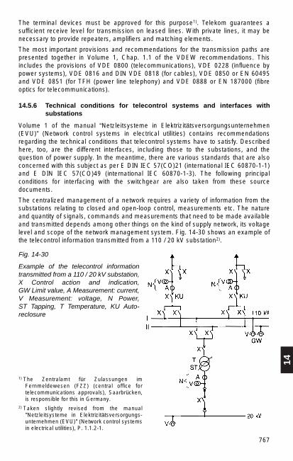
14
767
The terminal devices must be approved for this purpose1). Telekom guarantees asufficient receive level for transmission on leased lines. With private lines, it may benecessary to provide repeaters, amplifiers and matching elements.
The most important provisions and recommendations for the transmission paths arepresented together in Volume 1, Chap. 1.1 of the VDEW recommendations. Thisincludes the provisions of VDE 0800 (telecommunications), VDE 0228 (influence bypower systems), VDE 0816 and DIN VDE 0818 (for cables), VDE 0850 or EN 60495and VDE 0851 (for TFH (power line telephony) and VDE 0888 or EN 187000 (fibreoptics for telecommunications).
14.5.6 Technical conditions for telecontrol systems and interfaces withsubstations
Volume 1 of the manual “Netzleitsysteme in Elektrizitätsversorgungsunternehmen(EVU)” (Network control systems in electrical utilities) contains recommendationsregarding the technical conditions that telecontrol systems have to satisfy. Describedhere, too, are the different interfaces, including those to the substations, and thequestion of power supply. In the meantime, there are various standards that are alsoconcerned with this subject as per E DIN IEC 57(CO)21 (international IEC 60870-1-1)and E DIN IEC 57(CO)49 (international IEC 60870-1-3). The following principalconditions for interfacing with the switchgear are also taken from these sourcedocuments.
The centralized management of a network requires a variety of information from thesubstations relating to closed and open-loop control, measurements etc. The natureand quantity of signals, commands and measurements that need to be made availableand transmitted depends among other things on the kind of supply network, its voltagelevel and scope of the network management system. Fig. 14-30 shows an example ofthe telecontrol information transmitted from a 110 / 20 kV substation2).
Fig. 14-30
Example of the telecontrol informationtransmitted from a 110 / 20 kV substation,X Control action and indication, GW Limit value, A Measurement: current,V Measurement: voltage, N Power, ST Tapping, T Temperature, KU Auto-reclosure
1) The Zentralamt für Zulassungen imFernmeldewesen (FZZ) (central office fortelecommunications approvals), Saarbrücken,is responsible for this in Germany.
2) Taken slightly revised from the manual"Netzleitsysteme in Elektrizitätsversorgungs-unternehmen (EVU)" (Network control systemsin electrical utilities), P. 1.1.2-1.

768
Interface telecontrol unit/substation
This interface carries information passing between the telecontrol equipment and thecontrol devices in the substation. For the telecontrol equipment, there are the following4 kinds of data input/output:– digital inputs,– analogue inputs,– digital outputs,– analogue outputs.
The classes of noise-voltage limit values and insulation requirements are shown inTables 14-8 and 14-9. The choice of class depends on the characteristics of theswitchgear.
Table 14-8
Noise-voltage limit values and insulation requirements for binary signals
Transverse voltage Longitudinal voltage
Operating limits 10 % power frequencyvolt. peak / peak 25 V ACreferred to UN 65 V DC0.2 kV H.F. (1) 0.3 kV H.F. (1)0.3 kV IMP (1) 0.5 kV IMP (1)
Destruction limits + 200 % UN DC (2)class 1 – 125 % UN DC (2)
200 % UN A. (2) 0.5 kV N.F. (1)0.3 kV H.F. (1) 0.5 kV H.F. (1)0.5 kV IMP (1) 1.0 kV IMP (1)
Destruction limits + 200 % UN DC (2)class 2 – 125 % UN DC (2)for telecontrol equipment 200 % UN AC (2) 0.5 kV N.F. (1)with series 0.5 kV H.F. (1) 1.0 kV H.F. (1)EMI barrier 1.0 kV IMP (1) 2.5 kV IMP (1)
Destruction limits + 200 % UN DC (2)class 3 – 125 % UN DC (2)for telecontrol equipment 200 % UN AC (2) 2.5 kV N.F. (1)connected direct to the 1.0 kV H.F. (1) 2.5 kV H.F. (1)switchgear 25 kV IMP (1) 5.0 kV IMP (1)
Insulation between (a) min 1 MΩ at 500 V AC (3)inputs and/or (b) min 10 MΩ at 500 V AC (3)outputs and/or (c) min 100 MΩ at 500 V AC (3)earths
Notes:
(1) N.F. = System frequency (usually 50/60 Hz)H.F. = Damped high-frequency oscillation, see IEC 60255-4IMP = High-voltage pulse
(2) The equipment must withstand this voltage for 1 min without harm.(3) Insulation class (a) is for normal applications. Insulation classes (b) and (c) may be used in
special cases.

14
769
Table 14-9
Noise-voltage limit values and insulation requirements for analogue signals
Transverse voltage Longitudinal voltage
Destruction limits + 50 mA DC (2) 25 V ACclass 1 + 24 V DC (2) 65 V DC
0.2 kV H.F. (1) 1.0 kV H.F. (1)0.3 kV IMP (1) 2.0 kV IMP (1)
Destruction limits ± 50 mA DC (2) ± 0.5 kV DCclass 2 ± 24 V DC (2) 0.5 kV N.F. (1)for telecontrol equipment 0.5 kV H.F. (1) 1.0 kV H.F. (1)with series EMI barrier (4) 1.0 kV IMP (1) 2.0 kV IMP (1)
Insulation between (a) min 1 MΩ at 500 V AC (3)inputs and/or (b) min 10 MΩ at 500 V AC (3)outputs and/or (c) min 100 MΩ at 500 V AC (3)earth
Notes:
(1) N.F. = System frequency (usually 50/60 Hz)H.F. = Damped high-frequency oscillation, see IEC 60255-4IMP = High-voltage pulse
(2) The equipment must withstand this voltage for 1 min without harm.(3) Insulation class (a) is for normal applications. Insulation classes (b) and (c) may be used in special
cases.(4) The values for class 3 in Table 14-8 apply here if telecontrol equipment is connected direct to
control devices at the switchgear.
General conditions for substations
In the substations, all the circuit-breakers and disconnectors to be remotely controlledmust have a power operating mechanism and a floating-potential make and breakcontact for indicating status. Transformers, arc-suppression and charging-current shuntcoils must be provided with additional floating contacts to indicate grading level andon-status. All enunciator relays working together with telecontrol devices must have afloating NO contact, and so that new changes of state can be detected the enunciatorcontacts must be closed only while the coil is energized. Relays for isolating againstexternal interference must be mounted close to the telecontrol equipment. Measuringsensors are required for remote measurement.
As part of the power equipment, all these interface devices must conform to therelevant IEC standards, for instance IEC 364, and if electronic to IEC 1010.
Commands
Commands to switching devices and transformers or graded arc-suppression coils aretransmitted by the telecontrol system via digital outputs as two-phase pulsedcommands of ≤ 60 V DC lasting 100 to 500 ms. Single-phase and one-and-a-half-phase output arrangements should be fitted with a switching monitor in the

770
process-side circuit. Disconnectors with longer operating times (10 – 15 sec) must beprovided with additional means of automatic control or additional timing elements.Plunger-type arc suppression coils can be activated continuously or converted locallyto step control. With a switching device such as a local/remote selector switch it mustbe possible to inhibit individual groups of commands or all commands from thetelecontrol substation.
Indications
Indications are passed individually via digital inputs to the telecontrol device, althoughthe enunciator contacts can be grouped to feed common return lines. Signals indicatingswitchgear settings must identify both positions. These two signals are usually obtainedfrom a changeover contact or an NC and NO contact. With isolators that move slowly,transmission of the intermediate position is suppressed by the telecontrol systemduring the isolator’s usual operating time. Signals in response to tripping should,wherever possible, be generated locally in each switchbay.
The signals can be continuous, of short duration or fleeting signals with times of ≥ 10 ms, the last two categories being stored by the telecontrol system until they areacknowledged. A DC signal voltage of 60 V should be used (48 or 24 V are alsopossible) so that even with considerable distances between switchyard and telecontrolstation any noise voltages remain below the signal-tripping value.
Measured values
The remote measuring sensors employed to convert the process data into standardizedvalues must have floating-potential outputs. The voltage at the output of open-circuitsensors must not exceed 100 V. They must not be damaged by short-circuits or opencircuits on the output side, nor in such cases have any unacceptable effects on theprimary transformers.
Buffer amplifier or lightning arresters should be provided to guard against overvoltages,particularly in high-voltage installations.
The expected input quantity for the analogue inputs of the telecontrol device ispreferably an injected unipolar or bipolar direct current, also if applicable an injected DCvoltage (1 mA, 2.5 mA, 5 mA, 10 mA, 20 mA, 1V, 10V). The entire measurement andtransmission chain, from switchyard to control centre, should conform to accuracy class 1.
Meter readings
Metered values are fed to the telecontrol system as counting pulses or codedcounter totals. The counting devices (primary coders) usually have 6 decades and BCDcoding at the output. A floating input is required for the digital inputs to the telecontrolequipment.
Connecting conductors
Only insulated wires and cables may be used to connect the telecontrol equipment tothe respective devices and plant components. Cables with conductors whose insulationis not moisture-proof must be suitably sealed at the ends if necessary. The wires andcables are best laid in underfloor gulleys or on trays or racks. If no gulley is available,the wiring to the apparatus must be protected with ducting, conduit, or similar. Earth

14
771
wires and shielding must be connected by low-impedance joints to rails linked to theprotective earth conductor. Signal lines must be routed away from power and controllines.
Power supply, premises
The telecontrol devices are usually connected to a secure power supply so that datacan still be sent if the power in the switching installation should fail. This is generally a60 V or 24 V battery (also 48 V in other countries), and occasionally a secure 220 V ACsupply. The requirements for power supply for telecontrol devices are summarized inMain Section 1 of IEC 60870-2-1 or in DIN EN 60870-2-1, also in VDEW ManualVolume 1, Chap. 1.3.4. In addition, all of Chap. 5.1 “Secured power supply” of Volume 5 “Auxiliary Equipment” covers the recommendations.
In addition to electrical requirements, the premises in which telecontrol systems areinstalled and operated must also satisfy certain conditions.
The premises must be dry with a room temperature between 0 °C and + 55 °C, in largesubstations + 5 °C to + 40 °C. Generally the telecontrol equipment shall be able tooperate without air-conditioning.
14.6 Load management, ripple control
14.6.1 Purpose of ripple control and load management
Ripple-control techniques enable power suppliers to control their widely dispersedconsumers from a central point. The principal object of this is load management, i.e. thesupply utility can influence the consumption of electricity by connecting anddisconnecting suitable items such as storage heaters, hot water heaters, heat pumpsetc.
Fig. 14-31 shows the uncontrolled load pattern between midnight and 3 p.m., the linesrepresenting quarter-hourly averages.
Fig. 14-31
Load pattern between midnight and3 p.m., shown as quarter-hourly averages

772
Electricity consumption throughout the day can be made more even by connectingconsumers when load is low- afternoons and at night – and disconnecting them at peaktimes – mornings, evenings. Power stations and transmission/distribution networks areloaded more uniformly. Depending on the network management policy, the system,comprising load management centre, ripple-control equipment (transmitter andcoupling) and ripple-control receiver, can be operated on either the open- orclosed-loop principle.
In the first case, the consumers are switched on and off according to a fixed timetable.In the second instance, the computer also measures the effective network load,calculates the trend in order to establish, in relation to a set value, the necessity forconnection or disconnection, and chooses the consumers to be affected by anycorrection required. The system thus functions like a digital feedback circuit.
Although the principal aim is load management, the power utilities also use ripplecontrol for other purposes, e.g. tariff control (peak rate, off-peak, special rates, etc.),controlling street lighting, neon signs or building illumination, and in special cases alsofire and other alarms, and for operating switchgear where there are no telecontrol links.
14.6.2 Principle and components for ripple-control systems
Under the principle of ripple-control technology, signal voltages with frequencies of 150 to 1350 Hz must be injected briefly at a few places in the power supply system (50 or 60 Hz), in general in the substations of the distribution network, for the durationof the information transmission. The signals consist of a train of pulses in telegram formwith an injection level of 1 to 5% of the system voltage. They can be receivedthroughout the supply network, decoded by ripple-control receivers and converted intoswitching commands.
The telegrams have a distinctive pulse sequence for each kind of signal and arepreceded by a starting pulse, while modern systems also have an interrupt pulse(Fig. 14-32).
The ripple control frequencies are determined in relation to the harmonics of thenetwork frequency, which can assume values up to 8 %, and of neighbouring controlfrequencies. The middle frequencies of broad-band systems are arrangedsymmetrically at 33¹⁄₃ Hz intervals, for example, between the odd-numbered harmonicsof the network frequency (e.g. 150 Hz, 250 Hz etc.), while those of narrow-bandsystems are inserted accordingly (Fig. 14-33).
Where electricity networks are inductively linked with each other through a higher ordervoltage level, certain regulations must be observed when operating a ripple-controlsystem so that the ripple control facilities of adjacent supply utilities do not interfere witheach other. In Germany, the Federation of German Electricity Companies (VDEW) incollaboration with the manufacturing companies has issued “Recommendations forfrequency planning in ripple control installations”1). These stipulate the audiofrequencies and limit the residual audio frequency level in the higher-order network toa maximum of 0.3 % Un.
1) Source: Ringbuch der Energiewirtschaft, Abschnitt 234, 3 bis 5

14
773
Fig. 14-32
Trains of control pulses with and without interrupt pulses ST= starting pulse
Fig. 14-33
The harmonics of a 50 Hz network
Preferred ripple controlfrequencies
With new installations, frequencies of 150 to 450 Hz (the bottom part of the permittedfrequency band) are preferred because of better propagation conditions and a moreuniform distribution of levels, i.e. reduced resonance effects due to the powertransformers and compensating capacitors being connected in series. In older systemsor in special cases, higher ripple-control frequencies (up to approx. 1600 Hz) may alsooccur.
The requisite audio frequency voltages and currents are injected into the supplynetwork by static inverters followed by either series or parallel couplings.
Filtering out the audio frequency voltages, decoding the telegrams and then convertingthem into switching commands is done by ripple control receivers, which can beconnected to the consumer’s network (e.g. 220 V) wherever desired. Switchingoperations are generally controlled with the aid of ripple-control technology in low-voltage networks. If switching operations also need to be controlled in the distributionnetwork in special cases, the ripple-control receiver is connected via voltagetransformers.
774
The transmitter units are connected to the central load management computers bydedicated telecommunication channels, e.g. VFT channels.
New ways of operating ripple-control systems have become possible as the result of anew technique which allows the receivers to function as “remote-controlled timers”.
With this method, changeover times can be stored in the switching program orschedule, and then activated by the internal clock. The timetable can also be modified,adjusted according to temperature for instance, from the central command point.
It is then only necessary to send synchronizing signals from the command centre to thereceivers, perhaps once a day, so that the receivers can continue to functionindependently.
The control system is thus unaffected by outside influences. In consequence, thecentral ripple control equipment and the power distribution network serving as thecommunication channel must no longer be 100 % available in order to be certain thatthe appropriate control action always takes place. A protocol for transmission withsecured data now exists to accommodate this new approach.
The equipment of control centre, transmission equipment and receivers must thereforeconform to the protocols both of conventional ripple control techniques and ofdata-protected transmission.
14.6.3 Ripple-control command centre
The process is controlled and monitored centrally from the load management unit.
Its main duties are: – Execution of time- and event-based control actions according to defined time
schedules. – Display of receiver status. – Continuous measurement of system load and calculation of load trends within a
billing interval (e. g. 15 minutes). – Determining power corrections and scheduling consumers for connection /
disconnection.– Control and monitoring of transmission equipment and of transmitted pulse trains by
exchanging data with the substation controllers. – Displaying tables and curves on video terminals. – Printing out reports. – The new technology also requires means of registering the time schedules stored in
the decentralized receivers, supporting the second secured transmission protocol,etc.

14
775
14.6.4 Equipment for ripple control
Ripple-control systems are the equipment required for injecting the audiofrequencysignals into the distribution network.
The entire system comprises an audiofrequency transmitter, which generates aconstant output voltage of a defined frequency, the connection for injecting theaudiofrequency voltages or currents into the distribution network at the required levelvalues, e.g. 1.5 % of the rated system voltage, and the substation control devices.These controllers continually exchange data with the command centre, generateconventional or secured-data control telegrams, control and monitor the transmitter,keep check of the signal level and detect fault conditions. The station’s status isregularly transmitted to the command centre.
Ripple-control transmitters
Ripple-control transmitters are static converters which rectify the network voltage (e. g.50 Hz/380 V), and by triggering power semiconductors (thyristors or transistors)convert the DC voltage into audiofrequency voltages which are passed as athree-phase signal to the transmitter output.
Depending on the injection level, network structure and losses at the couplings, roughly0.1 % of the network power is needed for the transmitters. When injecting into 12 kVand 24 kV networks, this means that outputs of 15 to 150 kVA are required and forinjection into the 110 kV network outputs of 400 to 1500 kVA.
ABB RTS 400 transmitters of the S.P.I.D.E.R. LMS family have electronic currentlimitation and can be matched to the transient behaviour of different kinds of coupling.The same transmitters can be used for parallel and series couplings.
Coupling
The audio frequency generated by the ripple control transmitter must be superimposedover the distribution network at the required injection level and must be as loss-free aspossible, and in reverse the system voltage and its harmonics must be dampenedenough to prevent the transmitter from negatively influencing the process. This is thetask of the coupling. A distinction is made between inductive (series) coupling andcapacitive (parallel) coupling.
The choice of coupling technique depends on the impedance ratios due to the selectedripple control frequency, as these influence the signal and crosstalk levels. Butimportant too, is the design of the station being fed with the injected signal, togetherwith installation aspects (presence of high-voltage switchbays for parallel coupling) andoperational considerations.

776
Parallel coupling, Fig. 14-34a
Parallel coupling is preferred for higher audio frequencies. The voltage source is in thiscase in parallel with the ripple-control network ZA (see equivalent diagram). The audiofrequency current across the shunt of transformer ZT and high-voltage network ZH musthowever be provided in addition to the current from the ripple-controlled network.
Coupling to the 50 Hz network is effected by a series resonant circuit matched to theaudio frequency. The capacitor is on the network side and almost the entire networkvoltage drop occurs here. The ratings of high-voltage capacitor and couplingtransformer are governed by the audio frequency and the total network impedance (ZA parallel to ZT and ZH) and the signal level.
Fig. 14-34
Principle and equivalent diagrams ofparallel and series coupling of ripple-control transmitters: 1 Higher-order network, 2 System beingcontrolled, 3 Power transformer, 4 Ripple-control transmitter,
Series coupling, Fig. 14-34b
Series coupling is used mainly with low frequencies where, as the equivalent diagramshows, the inductive voltage drop across transformer ZT and high-voltage network ZH issmall compared to the network ZA with ripple control .
The coupling is inductive, injection being via an instrument transformer or powertransformer. The audio frequency transmitter output voltage is transformed to therequired network injection level, e.g. 1.5 % of the system voltage, or 173 V with 20 kV/3.
The 50 Hz network currents (instrument transformer) or 50 Hz network voltages (powertransformer) are reflected back to the transmitter side. With instrument transformerinjection, the transformed 50 Hz current is passed through a 50 Hz series circuit (seeFig. 14-34b), while with power transformer injection the 50 Hz reverse voltage isblocked capacitively. The instrument transformer method has the advantage over thepower transformer of smaller network voltage drops, but is less suitable for higherthroughput ratings.
5
6
78
a) Parallel coupling5 Coupling transformer6 Coupling capacitor
b) Series coupling7 Series capacitor8 Instrument transformer / power transformer (for coupling)

Fig. 14-35
Broad-band response characteristics of ripple-control receivers for commontransmission frequencies, Response characteristics of receivers, Harmonicvoltage level of network, UN Network voltage, f Audio frequency, UTF Audio-frequencyvoltage
14
777
14.6.5 Ripple control receivers
Most of the ripple control receivers installed at the consumer’s end evaluate the pulsetrains of a defined frequency superposed on the 50 Hz supply, and convert them intoswitching commands. According to IEC 1037, which covers ripple control receivers, theguaranteed functional voltage must be 0.5 % and the guaranteed non-functionalvoltage 0.3 %. This means that all receivers in the network must be sure to respond toaudiofrequency voltages equal to or greater than 0.5 % of the network voltage, andrefuse to respond to values equal to or less than 0.3 %.
The principal components of a conventional ripple control receiver are the filter module,the telegram decoding unit and the output relay stages.
The filter unit has a pass band optimized to the chosen control frequency, and mustadequately suppress the unwanted frequencies, e.g. system harmonics orneighbouring control frequencies. A distinction is made between narrow-band andbroad-band systems, see Fig. 14-35, i. e. filters with greater or lesser selectivity,corresponding to longer and shorter settling times, or telegrams of longer or shorterduration.

778
Fig. 14-36
Filter curve of a digital filter with optimum suppression of system harmonics and definedneighbouring frequencies at 8 ¹⁄₃ Hz intervals
Receivers with digital filters show particularly good characteristics, suppressing systemharmonics and frequencies very effectively at defined intervals of 8¹⁄₃ Hz for example,see Fig. 14-36.
The decoding units can evaluate telegrams generated by different ripple-controlmethods, e.g. Semagyr, Decabit, Ricontic, etc. Identification is by means of so-calledsystem parameters. The telegrams are usually encoded in m-out-of-n or m-times-ncodes.
New types of ripple control receiver are able to process in parallel both conventionaltelegrams and telegrams with data protection. This protocol is defined by a statementof block length, CRC of the block length, statements of function specification andaddress specification, CRC of the complete data block and an active end bit. Theprotocol is used for all kinds of purposes, such as transmission of switching commands,remote assignment of parameters (switching times, enabling/disabling of switchingschedules, and so on) and sending synchronizing signals, etc.
Modern receivers can thus operate on the “distributed intelligence” principle andperform functions independently.
The devices are generally installed on meter panels or directly on the meter terminalcover with the use of a special terminal cover (see DIN 43861).
Technical requirements and test procedures are described in the VDE 0420 standardand must be observed.

15
779
Table 15-1Application for stand-by power systems
User group
public assembly areas, shop and office buildings, banks, insurance companies, control centres.
high-rise buildings, hotels, government and administration buildings, conference centres, institutions, laboratories.
hospitals
warehouses and refrigerated storage
communications centres, data processing centres.
airports, air traffic control
railway stations
road tunnels,highway intersections
(continued)
Equipment with secure supply
emergency lighting as per DIN VDE0108
security, monitoring andpower supply systems.
as per DIN VDE 0107 and 0108, specialregulations, AV SV and ZSV network forsecurity, monitoring and power supplysystems, operating room lighting.
cooling units, security systems.
data processing systems, air-conditioningsystems.
control centres, runway, tower andemergency lighting, radio and radarsystems, data processing systems, aircrafton-board systems (400 Hz) for groundpower.
control centres, emergency lighting,monitoring and signalling systems.
lighting, ventilation, monitoring andsignalling systems
publ
ic a
nd c
omm
erci
al b
uild
ings
traf
fic15 Secondary Installations
15.1 Stand-by power systems
15.1.1 Overview
Stand-by power systems supply power to electrical equipment if the supply from thepublic distribution system is interrupted by faults or if a direct supply does not seemfeasible for technical or business reasons.
The following grouping is based in the different requirements: – emergency power systems,– auxiliary power systems, – frequency converters.

Table 15-1 (continued)
Applications of stand-by power systems
User group Equipment with secure supply
radio systems and tele- telecommunications devices and communications exchanges, installations, telecontrol systems,relay stations, energy monitoring and power equipmentauxiliary equipment supply substations
manufacturing and safety, monitoring and power supplyfunctional processes installations, process computers,
automation.
780
indu
stry
tele
com
mun
icatio
nsan
d en
ergy
trans
miss
ion
15.1.2 Stand-by power with generator systems
Generators with diesel engines are preferred for providing stand-by power toconsumers for which there is sufficient time for starting a power generator; see DIN6280 Parts 1 to 15.
The generator sets are used to generate power for– emergency power supply installations that supply the regular consumers in the event
of failure of the regular power supply,– peak load operation to cover daily demand peaks,– auxiliary supply of cogenerating systems with heat or current-controlled operation,– installations in continuous operation without an adequate power supply system.
Diesel engines are most frequently used for emergency power systems. Units with anoutput above 100 kW are normally supplied with turbo charger only. High-speedmachines with a rated speed of 1500 min–1 are mostly used. As well as better power-to-weight ratio, this allows better adaptation to synchronous generators of the standardtype (4-pole design). However,diesel engines with turbo charger do have thedisadvantage that they cannot produce their rated output in one stage.
The power generators used may be asynchronous generators (economical) or forinstallations of higher output, they can be alternators. The most common alternatorshave a brushless design. A built-in self-excited three-phase stationary-pole exciter withrotating diodes supplies the rotor current. The voltage is regulated in the three-phaseexciter field. If fast compensation of the generator voltage is required, self-excitedcompound generators (constant-voltage generators) are to be preferred. Electronicvoltage controllers are equivalent to the compound regulators.

15
781
The demands on the power supply of the consumers depend on the application. Theoperational response of the generator set must be able to meet the consumer’srequirements. The following types are classified according to the application:
Type 1, low demands on the voltage and frequency responseType 2, voltage response generally conforming to that of the public systemType 3, increased demands on the voltage and frequency responseType 4, maximum demands on the voltage and frequency response
The sets must be selected depending on the type. When rating the power of thegenerator, the connected loads of all power consumers must be determined, taking intoaccount the simultaneity factor and the largest consumer that is to be connected. Theconnected load should be 60%-70% of the rated generator set output to ensuresufficient reserve power for reactive power requirements and switching operations. If 6-pulse three-phase rectifiers are connected as consumers, the output of the set must beadequately rated because of the resulting harmonics (overdimensional). In addition tothe intrinsic response of the diesel engine and generator caused by designcharacteristics, the size and type of the connected consumers have a decisiveinfluence on the required generator power. So with turbocharged diesel engines, abase load already provides better frequency response (turbine pre-acceleration). Rotordamping, type of excitation and overexcitation capacity are the main influences on themaximum voltage dip for the generator.
Typical values for the speed and voltage response are specified in DIN 6280 Parts 1 to13 and the standard ISO 8528 Parts 1 to 6. Small generators (<10 kVA) are subject tothe standard ISO 8528 Part 8.
The machine room should be sufficiently large. Rooms that are too small makeoperation and maintenance difficult and the ventilation problem is often difficult to solvesatisfactorily. The questions regarding setup with proper noise isolation and fuelstorage (observe TÜV regulations) are also important, as is the problem of putting theequipment into place and its accessibility once installed. There must be a 1 m widespace all around the set under all circumstances. The space required is alsodetermined by other installations such as fuel tanks, sound absorbers, closed-circuitcooling, batteries and switching and control equipment; see also Section 4.7 StructuralRequirements.
782
The core of the automatic controller for emergency generator sets is the “ABBneacontic automatic start/stop” with a programmable controller (Procontic family orthird-party). It controls the following tasks:
“automatic” mode– all-pole system voltage monitoring– start command in the event of system fault (preferably time-delayed)– starting procedure– repeated start if applicable– operational monitoring– control of auxiliary equipment– monitoring of generator voltage– switching from network to generator operation (interlocked) or initialization
of parallel circuit.– detection of return of system availability– delayed automatic return switching of consumers from generator to network
operation with and without interrupting power supply.– aftercooling– shutdown– cancellation of the shutdown procedure in the event of another system fault
while the set is still running and immediate supply of power.
“manual” mode– manual operation for startup and shutdown. Interlocked switchover from
network and generator mode and back.
“test” mode– test operation for checking all automatic processes (including transfer of
power supply).– test operation for checking all automatic processes (not including transfer of
power supply).– automatic transfer of power supply if the system fails during test mode
operation.
“Off” mode– all equipment operation blocked, e.g. for maintenance. The power supply to
the consumers is not interrupted.
“EMERGENCY OFF” mode– with mechanically interlocked “OFF” position– stops in the event of danger to personnel or installation, regardless of the
selected mode.
Fault monitoring operates at a higher level than all other operating modes and displaysthe fault message and shuts down the generator if required.
A generator operating in “automatic” mode can, depending on its size, take oversupplying power after 10–15 s. Additional measures such as heating the room,preheating lubricant and coolant, assisted starting, compressed air starting and high-speed excitation can reduce this time to 5–10 s.
15
783
The automatic transfer synchronization ensures uninterruptible switchover of theconsumers from the generator to the network and from the network to the generator,e.g. ABB synchrotact 4 (see also Section 14.3.6).
Emergency power systems with several generators operating in parallel require anautomatic synchronization device for parallel switching. Another option is startingsynchronization. This involves several generator sets being simultaneously switched inparallel over busbars during starting. The consumers are separated from the busbarsduring this process.
The use of equipment for automatic effective and/or reactive power sharing enables theoutput to be distributed in accordance with the percentage ratio of the load capacity ofthe individual generator sets.
An additional device (cosϕ controller) makes it possible to retain a setpoint for thedesired power factor for parallel system operation.
15.1.3 Uninterruptible power supply with stand-by generating sets (rotating UPSinstallations)
Rotating UPS installations are characterized by a generator running continuously at itsrated speed. Its output must be sufficient to supply power to all consumers dependenton an uninterruptible power supply. This also applies for the design of the associatedmechanical generator sets.Rotating UPS installations are classified for the possible override time as follows:– converter and flywheel for short-term override (about 1 s),– converter and storage battery for part-time override (to about 30 min.),– converter and flywheel and coupled diesel machine for long-term override (practically
unlimited).
Uninterruptible power systems
The classical design of an uninterruptible power set has the most importantcomponents, a diesel engine, an electromagnetic clutch, a flywheel, a three-phaseasynchronous motor and a three-phase alternator, installed on a common base frame(Fig. 15-1a).
The asynchronous motor is connected to the public power supply and runs thegenerator with the flywheel. The consumers that require uninterrupted power arecontinuously supplied with power from the system through the three-phase converter.The diesel engine is uncoupled and not operating at this time. In the event of a systemfault, the asynchronous motor is shut down; at the same time the magnetic clutch isclosed and the diesel engine is started by the flywheel.
During the transition from the faulty network to emergency diesel operation, theflywheel alone supplies the driving force for the generator while simultaneouslysupplying the energy to start the diesel engine. The flywheel start brings the dieselengine to its working speed within 1 . . . 1.2 s. This virtually precludes a failed start.

While in the first standard design described a motor generator supplies the consumersthat require protection, in many cases one single electrical machine (reversingmachine) is sufficient. It uses the available system voltage to drive the flywheel as asynchronous motor and operates as a diesel generator in the event of a power failure.Fig. 15-1b illustrates the principle of an uninterruptible power system with asynchronous reversing machine.
See Figs. 15-1c) and 15-1d) for other options.
784
Fig.15-1 Basic design of uninterruptible power sets: a) with induction-synchronous generatorset, flywheel and coupled emergency power diesel engine; b) with synchronousreversing machine, flywheel and coupled emergency power diesel engine, c) with directcurrent three-phase converter, flywheel and coupled emergency power diesel engine,d) with direct current-three-phase converter and storage battery separate from network;N network lead, U clutch, V consumer, S flywheel, B battery, K magnetic clutch, D emergency power diesel engine
Fast-start power sets
Fast-start power sets are special emergency power systems with flywheels that can beused where short-time interruptions of approximately 250 ms are permissible. Theirdesign is generally similar to the uninterruptible power set with converter set. Thedifference is that with the uninterruptible power set, the generator supplies powercontinuously to the consumers while the consumers connected to the fast-start powerset receive their energy from the network.
The total cost of all rotating UPS installations (purchase, maintenance, operation) ishigh. For this reason, they are primarily used with high power requirements.

15
785
15.1.4 Uninterruptible power supply with static rectifiers (static UPS installations)
Uninterruptible power supply systems that operate with static rectifiers and storagebatteries are increasingly being installed in many areas, particularly for small to mediumoutput applications.
Operation
ABB UPS installations are based on a rotary converter. The UPS circuit diagram showsthe six most important components (Fig. 15-2):
– rectifier/battery charger (6-pulse) (GR)– battery (B)– inverter (WR)– static reversing switch (SW)– static bypass (SB)– maintenance bypass (WB)
All components are installed in one housing. The controller electronics for the rectifier,inverter and the bypass area are completely independent of one another. This meansthat a fault in one area cannot cause a fault in the adjacent area.
Features
UPS functionThe Uninterruptible Power Supply (UPS) is connected to the circuit between the powersupply network and the power consumers (load). They are designed to guarantee aconstant voltage supply for the load. If a network failure occurs, it can supply the loadfor a preset period (autonomous period). The UPS has also other advantagescompared to conventional supply systems (network, engine-powered generators, etc.):
Better output characteristicsMonitoring the UPS output voltage and frequency guarantees constant output power.Variations in the system voltage and frequency, which are generally present in electricalpower systems, do not influence the output voltage of the UPS.
Decoupling system distortionsThe double conversion from AC to DC and back to AC filters out all system distortions.All UPS consumers are also fused for protection against power system faults, whichcan occur in industrial power supply systems. This is particularly important for sensitiveelectronic equipment such as computer systems, control systems and medicinalequipment.
Fig.15-2
UPS circuit diagram
WB
IBY
B
SB
SW~
GR=
=WR~
IRE
IRP IUG
IB

786
Complete protection against power system faultsIf the power supply system fails, the UPS supplies energy to the load from the battery.The battery is connected to the UPS rectifiers and inverters. The inverter suppliespower to the load.
During standard operation, the inverter receives energy from the rectifier. The rectifierthen charges the battery at the same time.
In the event of a power system fault, the connected battery automatically suppliespower to the inverter. This means that the power supply to the load continues withoutinterruption. However, the battery can only supply the load for a specified period(autonomy period). If longer periods of autonomy are required, it is worthwhilesupplying the UPS with a diesel generator as an emergency power supply. In this case,the autonomy period is calculated for the period between network failure and fullgenerator power.
Rectifier/battery charger
In the standard configuration, the charger is a 6-pulse three-phase rectifier. It convertsthe network AC voltage to DC voltage. It is normally connected directly to the powersupply system via commutating reactors (no galvanic isolation). The commutatingreactors reduce the system perturbations of the rectifier. The charger feeds the batteryand the inverter. The battery is connected to the charger via a saturable reactor toreduce the residual ripple of the DC voltage. This ensures maximum battery life.
The rectifier is designed to supply the inverter and charge the battery with the maximumloading current simultaneously at maximum load. The floating charging voltage forstandard batteries (maintenance-free lead battery) with 192 cells is kept constant at432 V (2.25 V per cell). The battery is charged with I/U characteristic. This means thatthe charging current limit is reached by reducing the intermediate circuit voltage. Thisensures that the battery is not damaged by excessive charging current. A 12-pulserectifier is optional and requires the addition of a second rectifier bridge in the UPScabinet and a phase-shifting transformer in a separate accessory cabinet.
Fig.15-3
6-pulserectifier circuit diagram
Fig.15-4
12-pulserectifier circuit diagram
Vac VdcVac Vdc
B+B–
+– +
–IRP IRP B+ B–
L1L2L3
L1L2L3
~
~~
∆D
Y11

15
787
Battery
The battery supplies the inverter in the event of a short interruption or a system failure.The battery is designed to continue to supply the load for a specified period (autonomyperiod) depending on the battery capacity and the actual load.
The number of cells in the battery depends on the type and also on the customer-specific requirements. The standard number is 192 cells for lead-acid and 300 cells forNiCd batteries. The battery capacity (Ah) depends on the UPS output and the requiredautonomy period.
Inverter
The inverter, which is supplied by the rectifier or the battery, converts the DC voltagefed from the rectifier or the battery into a.c. voltage with constant voltage and frequency,a form of power suitable for the power supply of highly sensitive electronic equipment.
Pulse duration modulation is used to generate the AC voltage. The output voltage(harmonic content < 1%) is smoothed by a high operating frequency of the powersemiconductor and the use of an output filter (transformer and capacitors).
Every phase-to-earth voltage at the output of the inverter is regulated separately. Thisensures that the UPS output voltages remain constant even under very non-symmetrical loads.
For protection of the inverter, the inverter electronics restrict the inverter output currentto 150% of the rated current in the event of a short circuit. In the event of overload, itrestricts the inverter output voltage to no more than 125 % of the rated power. If aserious overload occurs, it automatically switches to bypass mode, if the bypass isavailable.
Saturation monitoring or an “electronic fuse” protects the inverter transistors fromdestruction by short circuits.
Fig.15-5
Inverter circuitdiagram
VacVdc
L1L2L3
N~
+
–
∆D
ZO
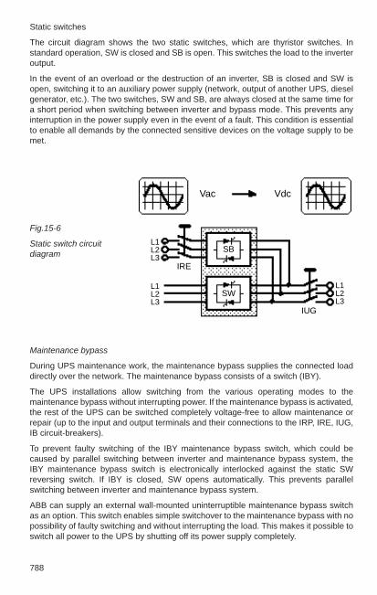
788
Static switches
The circuit diagram shows the two static switches, which are thyristor switches. Instandard operation, SW is closed and SB is open. This switches the load to the inverteroutput.
In the event of an overload or the destruction of an inverter, SB is closed and SW isopen, switching it to an auxiliary power supply (network, output of another UPS, dieselgenerator, etc.). The two switches, SW and SB, are always closed at the same time fora short period when switching between inverter and bypass mode. This prevents anyinterruption in the power supply even in the event of a fault. This condition is essentialto enable all demands by the connected sensitive devices on the voltage supply to bemet.
Maintenance bypass
During UPS maintenance work, the maintenance bypass supplies the connected loaddirectly over the network. The maintenance bypass consists of a switch (IBY).
The UPS installations allow switching from the various operating modes to themaintenance bypass without interrupting power. If the maintenance bypass is activated,the rest of the UPS can be switched completely voltage-free to allow maintenance orrepair (up to the input and output terminals and their connections to the IRP, IRE, IUG,IB circuit-breakers).
To prevent faulty switching of the IBY maintenance bypass switch, which could becaused by parallel switching between inverter and maintenance bypass system, theIBY maintenance bypass switch is electronically interlocked against the static SWreversing switch. If IBY is closed, SW opens automatically. This prevents parallelswitching between inverter and maintenance bypass system.
ABB can supply an external wall-mounted uninterruptible maintenance bypass switchas an option. This switch enables simple switchover to the maintenance bypass with nopossibility of faulty switching and without interrupting the load. This makes it possible toswitch all power to the UPS by shutting off its power supply completely.
Fig.15-6
Static switch circuitdiagram
Vac Vdc
SB
SW
IUG
IRE
L1L2L3
L1L2L3
L1L2L3

15
789
Hot stand-by operation
A hot stand-by UPS system is basically two (or more) UPS installations, which operateindependently of one another. Each installation can supply the load at any time.– All installations are in operation continuously, but at any time only one UPS is
supplying the load.– If a fault occurs in the active installation, another installation is ready to take the load
without interrupting the output voltage; i.e. a constant power supply to the load isguaranteed at all times.
– The load is only supplied from the static bypass if there is no inverter in the systemable to take the load.
Fig. 15-7
Internal maintenancebypass circuit diagram
Fig. 15-8
External maintenancebypass circuit diagram
Fig. 15-9
Hot stand-by operation circuit diagram
WB
IBY
IUG
IRE
IRP
IBB
SB
SWGR=
~ =WR~
IRE
IRP
IRP
IRE
IUG
IUG
WR
SB
SWGR~= WR
WR
~
~~
GR
GR
IBY
IUG
IRE
IRP
IBB
SB
SWGR=
~ =WR~
SW
SB
IBB
IBB
=
==

790
Redundant parallel operation
A parallel UPS system consists of two to six UPS installations switched in parallel overwhich the load is equally distributed. Every installation has its own static bypass (SB),this ensures SB redundancy in the system. This means that if one SB fails, the bypasssystem is still always available.
The parallel system does not have a central controller. Each installation has its ownseparate paralleling electronics to monitor all functions and to provide full redundancy.
Parallel operation
This configuration is identical with that of the redundant parallel operation, except thatthe rated power of the UPS systems normally conforms to the output power and thereare no redundant installations. UPS installations of varying output can be parallelswitched in this configuration, because the load is distributed proportionally to theinstallation output. The parallel configuration conforms to the redundancy configurationif the load has been reduced to a value that allows the system to continue to supply thereduced load with one (or more) installation(s) fewer. This makes one (or more)installation(s) redundant and the controller is identical.
Fig. 15-10
Parallel operationcircuit diagram
SB
SWIUG
USV 1
IRE
IRPWRGR
==
~~
IBB
WB
IUSSB
SWIUG
USV 2
IRE
IRPWRGR
==
~~
IBB
SB
SWIUG
USV 3
IRE
IRPWRGR
==
~~
IBB

15
791
Notes on all ABB UPS types:System configuration: on-line (double conversion) setting ranges for input and output voltages:380/220 V/400/230V/415/240 V
Radio interference suppression: limit class A as per EN 50091-2
Design: in accordance with European directives 89/336/EEC and 73/23/EEC
ABB UPS installations meet the requirements of European directives 89/336/EEC and73/23/EEC and of EN 50091-2 (1995) and EN 50091-1 and therefore have the CEmark.
ABB UPS installations conform to limit class A as per EN 50091-2The installation may radiate electromagnetic fields in its immediate vicinity. In this case,the operator is expected to conduct additional measurements or take action.
Table 15-2
ABB UPS system range with technical data
Type ABB/Mini ABB/MP ABB/S400 ABB/PX4
Unit capacity kVA 0.5 to 10 7.5 to 25 10 to 120 150 to 400
Input voltage V 230/1ph. 400/230 400/230 400/230permissible voltage tolerance % ± 10 ± 10 ± 10 ± 10
Input frequency Hz 50 (60) 50 (60) 50 (60) 50 (60)permissible frequency tolerance % ± 5 ± 5 ± 5 ± 5
Output voltage V 230/1ph. 230/1ph. 400/230 400/230voltage tolerance at: – symmetrical load % ± 3 ± 1 ± 1 ± 1 – at 50 % step change
in load % ± 4 ± 4 ± 4 ± 4 – at 100 % step change
in load % ± 6 ± 10 ± 5 ± 10
Output frequency Hz 50 (60) 50 (60) 50 (60) 50 (60)frequency tolerance % ± 0.5 ± 0.5 ± 0.5 ± 0.5
Distortion factor % < 4 < 3 < 2 < 3
Current carrying capacity: – inverter 1 min. % 120 150 150 150 – static bypass 1 min. % 150 200 200 200
Total efficiency % 83 90 90 93
Noise level db(A) ca. 50 ca. 60 ca. 61 ca. 63

792
15.2 High-speed transfer devices
15.2.1 Applications, usage, tasks
In power and industrial plants, large motors and other important consumers must havea backup in case the general power supply system fails, because otherwise availability,production, profitability and safety will be restricted or people may be injured and theenvironment and process equipment may be damaged. With such high outputs, backupgenerators are no longer sufficient. A second power supply ready for immediateoperation is required. It is important for the second power supply to be independent ofthe effects of a fault in the general power supply system. The supply must come fromanother transmission network or a different power generator.
The fast transfer to the second power supply is generally done at the same voltage levelas the large consumers, i.e. in the rated voltage ranges up to 24 kV. However, in somesituations, the transfer is done in the low-voltage network or at the level of atransmission voltage. This can basically involve switching over one large consumer,such as a motor, and also switching over a whole group of important consumers linkedtogether over one busbar section.
The transfer must be done very quickly and without any serious feedback to theconsumers and power supply, i.e. the switching must be controlled with very shorttransfer times with regard to the physical processes in the network and at theconsumers. This task is handled by high-speed transfer devices, which are based ondigital hardware technology and can be integrated into every modern installationprotection design.
To take full advantage of the possibilities of high-speed transfer devices, the generaldesign must meet the following requirements:– there must be at least two, generally independent of each other synchronous power
supplies– circuit-breakers with short operating times– switchgear installation must be suitable for system transfers– fast protection relays for initiating the high-speed transfer device
Transfers initiated by operational conditions can be started manually using the high-speed transfer device, but in the event of a fault, the transfer system reactsautomatically.
Examples of applications of the ABB SUE 2 high-speed transfer device is shown inFigs. 15-11a and 15-11b.

15
793
Fig.15-11
Example of a switchgear installation with high-speed transfer devices a) Single busbar b) Single busbar with two power supplies
with two power supplies and bus sectionalizer
Power supply 1 Power supply 2
Power supply 1 Power supply 2
(2 systems)

794
15.2.2 Integration into the installation
Corresponding to its great importance, the high-speed transfer device must beconsidered at the planning stage of a switchgear installation and its secondarycomponents, because it communicates with many other station components (Fig. 15-12). There are interfaces to the following components, among others:– switchgear installation (circuit-breakers, voltage transformers, overcurrent relays etc.)– protection (block, transformer, differential, cable, undervoltage protection etc.)– control systems/control room (remote control, signalling system)– voltage supply (DC power supply).
Additional interlocking, releases or blocking in conjunction with other components maybe required because of the large number of individual design options for a switchgearinstallation as well as the operational conditions.
Fast, direct and undelayed starting by external protection relays is also important foroptimum conformity with all demands on the high-speed transfer device.
Switchgear
SUE 2
Controlsystem/control
roomVoltage supply
Protection
Fig.15-12
Installation interfaces
15.2.3 Design of high-speed transfer devices
The ABB Type SUE 2 high-speed transfer device primarily consists of the followingthree function groups:– logical processing module– digital phase comparison unit– test device
The logical processing module consists of a modular, programmable logic controller(PLC). All functions required for controlling the circuit-breaker, for interlocking, blocking,acknowledgements, signalling and monitoring are controlled by the PLC.
The digital phase comparison is implemented with an intelligent, programmablemicrocontroller unit. The unit has integrated A/D transformers, which read in therequired measurement voltages. Comparison of the electrical parameters of voltage,frequency and phase relationship is an extremely time-critical process, which issecured by its implementation in low-level assembly programming.

15
795
The test device enables the functioning of the high-speed transfer device to be tested,including a continuity test of the control coils of the circuit-breakers that they actuate. Italso provides information on the system status of the installation. In the event of a fault,an internal diagnosis provides detailed information on possible faults.
15.2.4 Functionality
The high-speed transfer device continuously compares the busbar voltage with thevoltage available in reserve. The transfer criteria are generated from the monitoringprocess of the voltage amplitudes, the frequency difference and the phase angle.
The different transfer situations described below are initiated at the moment of startingbased on the current power system status.
The high-speed transfer device must always be started externally. This is normallydone manually from the control room or initiated by suitable fast protection relays.Basically, if a limit value defined as an undervoltage in the current power supply isreached, an undervoltage initiation can also be independently generated. The transferdirection – either from the main to the reserve power supply or vice versa – isinformation taken from monitoring the corresponding circuit-breaker positions. Thehigh-speed transfer device is only ready for operation when both circuit breakers thatare to be actuated are definitely in different switching states (plausibility check) and arein operating position.
Switching commands from the high-speed transfer device to the circuit-breakers –bypassing all switchgear interlocks that might be present – are sent directly to thecontrol coils.
15.2.5 Types of transfer
The decisive criterion for the type of transfer is the power system relationships at themoment of starting the high-speed transfer device. In principle, the following transferoptions are available:– fast transfer– Transfer at the 1st phase coincidence– residual voltage transfer– long-time transfer
The preferred and most important functional principle of the SUE 2 high-speed transferdevice is to conduct fast transfers. If there are no prerequisites for this, the device offersadditional, optional function mechanisms.
A fast transfer occurs if the main and reserve power supply are quasi-synchronouswithin preset limit values, i.e. slip and phase angle between the networks are limitedand the reserve voltage is above a minimum value. During this process, the high-speedtransfer device sends OFF and ON commands to the circuit-breakers simultaneously.The pause without power that occurs for the consumers in this case depends almostentirely on the difference between the make and break properties of the switchgear.
796
A transfer in the 1st phase coincidence occurs when the networks were notsynchronized at the moment of starting but specific conditions are met. In this type oftransfer, the OFF command is sent immediately and the reserve power system isactivated in the 1st minimum of the difference of reserve and busbar voltage.
The high-speed transfer device uses predictive calculation to determine the course ofthe differential voltage and the time of the 1st phase coincidence. To compensate forthe processing time dictated by the equipment (SUE 2 mechanical system delay,circuit-breaker delay periods), the ON command is issued at an appropriate periodbefore the actual occurrence of the minimum differential voltage – within a previouslydefined switching window.
A residual voltage transfer is initiated if the networks are not synchronized at themoment of starting and a beat transfer is also not possible. In this case the OFFcommand is sent immediately to the feeder circuit-breaker and the ON command issent to the switch that is to be closed when the busbar voltage has decayed to a setpermissible value and the feeder circuit-breaker is safely opened. The reserve networkis activated independently from the phase angle and the slip.
There is also a residual voltage transfer if the starting is initiated by the undervoltagemonitoring implemented in the SUE 2 or by external undervoltage relays.
A long-time transfer is initiated if the busbar voltage cannot be monitored during atransfer (that does not occur as a fast transfer) (e.g. because of failure of an automaticdevice). The OFF command is sent immediately, but the ON command is only sent aftera defined period as is the return confirmation that the feeder circuit-breaker is open.
The conclusion is that the selection of the type of transfer at the moment of starting thehigh-speed transfer device is decisive. In general, fast transfers are initiated becausethe networks are usually synchronized. The principle of issuing commandssimultaneously to the circuit-breakers guarantees the shortest possible transfer timesand safe, virtually uninterrupted power supply. If the switch that is to be opened fails ona fast transfer, e.g. because of mechanical problems, the high-speed transfer devicedetects this state and the switch that was just closed is opened again after a presetperiod, thereby preventing non-permissible, long-duration coupling of the networks.
If the networks are not synchronized at the instant of starting, a fast transfer is notinitiated. The resulting dead times without power vary depending on the installation,with the load that is to be switched determining the run-down response of the busbarvoltage.
The various types of transfer can be selectively activated and deactivated dependingon the direction. This ensures that the optimum transfer concept for the entireinstallation can be implemented with regard to the special requirements.
A fast transfer is the smoothest type of transfer and in most cases guaranteescontinued operation of the installation with no interruption. The busbar voltagegenerally remains stable and the closing currents after the transfer are limited.

15
797
When conditions allow switching at the 1st phase coincidence, this type of transfer – afast transfer was not possible –- is the second best choice, followed by the residualvoltage-dependent and the long-time transfer. If the reserve networks are not stableenough for certain transfers, the high-speed transfer device can send signals to initiatetargeted load shedding before switching.
The high-speed transfer device is designed to initiate the optimum possible transferautomatically depending on the general conditions. The oscillograms in Fig. 15-13show some typical transfers.
1
2
3
1
2
3
4
Fig. 15-13 Oscillogramsa) fast transfer 1 = busbar voltage 2 = current main Feeder3 = current standby Feeder
b) residual voltage-dependent transfer1 = busbar voltage 2 = differential voltage (Ustandby - USS)3 = current main Feeder4 = current standby Feeder
a)
b)

798
15.3 Stationary batteries and battery installations, DIN VDE 0510,Part 2
15.3.1 Types and specific properties of batteries.
Battery sets are used in switchgear installations as sources of energy for network-independent power supply of controller protection, regulating and signal circuits andsimilar.
The battery direct voltage can also be used via inverters to generate “safe AC voltage”.In installations with modern secondary technology, the power supply modules forcomputers and the electronic protection and also standard data processing devicessuch as PCs, monitors and printers are supplied with safe alternating voltage (UPS)(Section 15.1.4).
Two types of cells are used in stationary batteries:– The closed cell has a sealed cell cover with one or more openings through which the
gas generated can dissipate or through which water can be added. The openings areclosed with suitable stoppers, e.g. fastener stoppers.
– The sealed cell is maintenance-free throughout its life and can generally be installedwithout regard to position. The internal gas pressure can be released through anautomatically closing cell valve.
Note:It is not possible to prevent the generation of oxygen and hydrogen in a lead-acid battery! A gasdensity seal is possible only with the NiCd battery. Its negative electrode is above the hydrogenpotential.
The nominal voltage and the capacitance of a battery are determined by the requiredservice voltage with consideration of the permissible voltage tolerance of the individualconsumers (switchgear and protection devices), the input power of the various powerconsumers, their duty factor and the type of current draw. Switchgear installationsprimarily use two types of batteries:
Lead-acid batteries with electrodes of lead and lead alloys and weak sulfuric acid aselectrolyte. They are used in switchgear installations, substations and power plants toprovide high power requirements for long operational periods, such as emergencylighting.
Important cell types used in lead-acid batteries:– OGI : with positive and negative grid plates– OPzS : with positive iron-clad plates– GroE : with positive high-surface-area plates– GroE-H : with positive high-surface-area plates, high-current design
Nickel-cadmium batteries with positive electrodes of nickel compounds, negativeelectrodes of cadmium and weak caustic potash solution as electrolyte.

15
799
Important cell types used in nickel-cadmium batteries:– with pocket-type plates, application type .. L*), preferred for switchgear installations– sintered cells, e.g. for aircraft– with bonded plastic plates, application types .. L, .. H and .. M*),– with fibre plates, application type .. H*), e.g. for motor vehicle batteries.
*) .. H = high current, short duration.. L = low current, long duration.. M = medium current, medium duration.
Advantages of NiCd batteries over lead-acid batteries:– high reliability– long life– small footprint– low maintenance costs– low reduction in capacity at low temperatures – fast recharging– high mechanical and electrical stability– good storage capacity– low-charge resistant – resistant to overcharging– low self-discharge – high cycle-capacity – no pole corrosion
Disadvantages of NiCd batteries over lead-acid batteries:– high price– lower cell voltage– less efficiency – no full capacity when charged with charge retention voltage– at high cyclic stress and high temperatures pocket-type cells may require new
alkaline electrolyte after some years – larger voltage window with charging/discharge
Electrical values of batteries (see also Table 15-3).
The DIN 40 729 standard defines the basic terms for batteries.
Nominal voltage:
The nominal voltage (UN) of a cell is a specified value. In the lead-acid battery it is 2.0 V, in the nickel-cadmium battery it is 1.2 V.
The nominal voltage of a battery is the product of the number of cells connected inseries and their nominal voltage.

800
Rated capacity:
The rated capacity (CN1) is the quantity of electricity that a battery can supply during
discharge over a defined discharge period (nominal discharge period tN) with theassociated rated current (IN) at nominal temperature, nominal density and nominalelectrolyte status without going below the end-point voltage (USN).
The maxim is: CN = IN • tN
The n-hour capacities are associated with a battery if it can be discharged with currentsdifferent from the rated current. The index n gives the discharge time tn in hours (e.g. C3 = 3-hour capacity).1) In international texts, C is the standard symbol for capacity.
End-point voltage:
The end-point voltage (US) is the set point below which the voltage must not fall duringdischarge with the assigned current.
The rated end-point voltage (USN) applies during draw with the nominal dischargecurrent (IN = CN/tN) for specifying the rated capacity CN.
Gassing voltage:
The rated voltage (UG) is the charging voltage above which a battery begins todischarge gas; in lead-acid batteries 2.40...2.45 V per cell, in nickel-cadmium batteries1.50 -1.55 per cell.
Charging factor:
The charging factor 1/ηAh) is the ratio of the quantity of electricity required for full chargeto the previously drawn quantity of electricity. (Reciprocal efficiency of the charging η Ah).
lnternal resistance:
The internal resistance of a battery cell R/cell is dependent on the cell temperature andthe charging or discharging status. The typical values given in Table 15-3 are based ona fully charged battery.
A contact resistance of 2 x 0.04 mΩ/cell can be assumed for the connections betweencells.
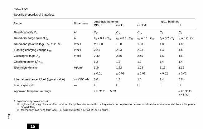
15
801
Table 15-3
Specific properties of batteries.
Name Dimension Lead-acid batteries NiCd batteriesOPzS GroE GroE-H L H
Rated capacity CN Ah C10 C10 C10 C5 C5
Rated discharge current IN A I10 = 0.1 · C10 I10 = 0.1 · C10 I10 = 0.1 · C10 I5 = 0.2 ·C5 I5 = 0.2 · C5
Rated end-point voltage USN at 20 °C V/cell to 1.80 1.80 1.80 1.00 1.00
Floating charging voltage ULE V/cell 2.23 2.23 2.23 1.4 1.4
Gassing voltage ULE V/cell 2.40 2.40 2.40 1.5 1.5
Charging factor 1/ ηAh — 1.2 1.2 1.2 1.4 1.4
Electrolyte density kg/dm3 1.24 1.22 1.22 1.19 1.19
± 0.01 ± 0.01 ± 0.01 + 0.02 ± 0.02
Internal resistance Ri/cell (typical value) mΩ/100 Ah 3.0 1.4 1.0 1.4 0.6
Load capacity1) — L H H L H
Approved temperature range + 5 °C to + 55 °C – 20 °C to + 45 °C
1) Load capacity corresponds to:H: high-current design for short-term load, i.e. for applications where the battery must cover a period of several minutes to a maximum of one hour if the power
network fails. L: for capacity load (long-term load), i.e. current draw for a period of 1 to 10 hours.
15

802
15.3.2 Charging and discharging batteries
All operation with batteries requires a regulated power source that recharges thebattery. It must also be capable of supplying the consumers directly, depending on theoperating mode. The required charging quantity for a lead-acid battery is 120%, and fora nickel-cadmium battery approximately 140 % of the previously drawn Ah. The self-discharge current of a lead-acid battery is about 0.2 % of the three-hour dischargecurrent; that is about 1 % of the 10-hour capacity daily. The quantity of the chargingcurrent depends on the capacity of the battery and the charging time. This informationis supplied by the manufacturer. In the case of lead-acid batteries the charging currentis generally equal to the discharge current with a three- to five-hour discharge. In thecase of nickel-cadmium batteries, the charging current should be equal to the dischargecurrent of a five-hour discharge. Once the gassing voltage has been exceeded, it mustbe reduced to approximately one third of the above-mentioned charging current andshould decrease further until charging is complete.
When batteries are fully charged, the charging voltage should be reduced to the floatingcharge voltage to prevent damage caused by continued gassing, temperature increaseand water loss.
Lead-acid batteries can be fully recharged with the floating charge voltage and retainfull capacity.
When NiCd batteries are charged with the floating charge voltage, they do not reach fullcapacity and therefore should always be charged at a higher voltage. Even if a NiCdhas been previously fully charged, it still loses some capacity when receiving floatingcharging voltage. This loss of capacity under floating charging voltage depends on theload on the battery and can be up to 10% of the rated capacity.
For faster charging, all batteries should be charged at a higher voltage with a finalautomatic fallback to the floating charge voltage. When commissioning and servicingbatteries, the charger should also have a boost charger device with automatic fallbackto the floating charge voltage.
Battery charger:
If the battery cannot be isolated when charging with a higher characteristic but thecharging voltage exceeds the maximum approved value at the consumer, the followingactions may be taken in the charger:– the use of counter-cells,– main and end cells, – DC stabilizer in the charger load-circuit output.
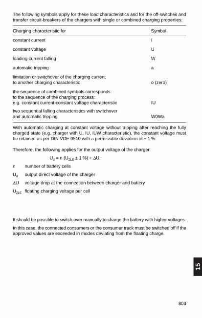
15
803
The following symbols apply for these load characteristics and for the off-switches andtransfer circuit-breakers of the chargers with single or combined charging properties:
Charging characteristic for Symbol
constant current I
constant voltage U
loading current falling W
automatic tripping a
limitation or switchover of the charging current to another charging characteristic o (zero)
the sequence of combined symbols corresponds to the sequence of the charging process: e.g. constant current-constant voltage characteristic IU
two sequential falling characteristics with switchover and automatic tripping W0Wa
With automatic charging at constant voltage without tripping after reaching the fullycharged state (e.g. charger with U, IU, lUW characteristic), the constant voltage mustbe retained as per DIN VDE 0510 with a permissible deviation of ± 1 %.
Therefore, the following applies for the output voltage of the charger:
Ud = n (UZLE ± 1 %) + ∆U.
n number of battery cells
Ud output direct voltage of the charger
∆U voltage drop at the connection between charger and battery
UZLE floating charging voltage per cell
It should be possible to switch over manually to charge the battery with higher voltages.
In this case, the connected consumers or the consumer track must be switched off if theapproved values are exceeded in modes deviating from the floating charge.

804
15.3.3 Operating modes for batteries
If consumers are supplied directly from a battery and the battery is disconnected from the consumers for charging, this is referred to as straight battery operation (Fig. 15-14a).
During parallel operation (Fig. 15-14b), consumers, rectifiers and battery arecontinuously connected in parallel. In this case, a distinction is made between bufferoperation (battery is used to keep constant voltage and to cover peaks) and paralleloperation (battery supplies power only if the rectifier fails, Fig. 15-15b). Paralleloperation predominates.
Under switchover mode, the battery is disconnected from the consumers; it is kept fullycharged. If the standard power source fails, the consumers are switched to the battery(Fig. 15-14c).
1 DC source, 2 consumer, 3 battery
Important note!
During project planning of auxiliary installations in which the secure alternating voltagewill be generated by rectifiers and inverters connected in series, the characteristics ofboth devices must be matched for each other for all loading cases. The selectivity of thetwo voltage potentials must be retained with load currents or short circuits.Correspondingly, the supplying device must be capable of supplying at five times therated current for a short time while retaining the voltage drop approved by the VDE.
1 2
L E
3
I
1 2
3
I
1 2
3
I
I
Fig.15-14
a) discharge-charge b) parallel operation: c) switchover operation:
a) b) c)

15
805
15.3.4 Dimensioning batteries
A large amount of data and operating conditions must be considered whendimensioning a battery.
It includes:– load current,– duration of load,– impulse load,– sequence of individual loads, – permissible voltage tolerance of consumers,– voltage drop on the connector cable,– ambient temperature,– end-point voltage of the battery,– selected measures for retaining voltage tolerances– proposed battery type.
Measures for retaining the voltage tolerances can include connecting of counter-cells,dividing a battery into main and end cells or using a stepup unit. A different procedureis used to determine the battery size depending on what measure is implemented.Battery manufacturers have suitable calculation programs. Detailed information can befound in IEEE 485 for lead-acid batteries and IEEE 1115 for Ni/Cd batteries.
Note:It is never sufficient to calculate the capacity of a battery from the product of current xdischarge time only.
15.3.5 Installing batteries, types of installation
Types of installationBatteries are usually installed on steel racks.The most convenient type of installation from the point of view of maintenance is on atiered rack.Stationary batteries are supplied in bolted or welded designs.
Inspection passagesDIN VDE 0510 specified that the rows of cells must be accessible by a passage. Thewidth of the passage must be at least 500 mm for floor-mounted racks and at least 800 mm for tier racks. However, practice has shown that these aisle widths are toonarrow, so the recommended widths for floor-mounted racks are at least 800 mm and1000 mm for tier racks.
Battery roomsThe structural design of battery compartments is specified in worksheet J 31 of theworking group for industrial structures (AGI: Arbeitsgemeinschaft für Industriebau).Battery compartments are accessible, enclosed compartments intended for installationof batteries for supplying electrical installations. As per DIN VDE 0510 and DIN VDE 0100 they are considered as– electrical premises/operator access area, if the installation is designed for a nominal
voltage of up to 220V– locked electrical premises/restricted access location, if the installation is designed for
nominal voltages over 220 V.The requirements for the structural design of battery compartments are considered inmore detail in Section 4.7.4.

806
15.4 Installations and lighting in switchgear installationsThe operation, control and monitoring of switchgear installations inside and outsiderequires that they be supplied with energy (unit) and lighting.
15.4.1 Determining electrical power demand for equipment
The power demand Pmax is calculated from the sum of the connected loads Σ Pi for theindividual consumer groups and multiplied by the demand factor g.
Pmax = Σ Pi · g
The requirement factor is based on values derived from experience; see Table 15-4.
Table: 15-4Typical values for demand factor g for:
offices switchgearinstallations installations
lighting 0.8 0.8receptacles 0.1 0.1air-conditioning, ventilation 1 1heating 1 1lifts 0.5 / 0.7 —kitchen equipment 0.5 —outside lighting (floodlight installations) — 1cranes — 0.7control and signalling equipment — 0.5data processing equipment depending on the individual case
See Table 6-6 for demand factors for other equipment.
Equipment for station services
The equipment for station services in switchgear installations is described in Section7.1 and 7.2.
In most cases, low-voltage distributors in the form of switch cabinets or distributorboxes are used, with all requirements for maximum operational dependability regardingdesign and equipment selection being met.
Important consumers and functions are supplied with direct voltage, which also ensuresan uninterrupted power supply even in the event of a malfunction with the use ofstationary batteries.

15
807
15.4.2 Layout and installation systems
The complex cable and wiring networks comprise a significant portion of the entireinstallation system. For this reason, the correct selection of materials and systemsappropriate for the application is particularly important. Installations with multiple firecompartments require appropriate barriers between them. If emergency exits areprovided, they must be installed in F90; materials conforming to DIN 4102 must beused. Fasteners and installation materials that are easy to install must be selected toallow economical installation. Proper tools and construction equipment are alsorequired to ensure rational installation work processes.
See Sections 6.1.7 and 13.2.4 for information on laying cables and wiring.
The manufacturer’s working guidelines must also be observed.
There are single modules and complete layout systems for the various layout types.
The fastening methods and layout materials must be selected in accordance with theanticipated stresses caused by mechanical, thermal, chemical or other environmentaleffects. The following must also be taken into account:
– adequate heat dissipation,– safe isolation of the power and communications circuits and the networks for stand-
by power,– open or covered configuration, – sufficient flexibility for changes and retrofitting, – technical fire protection measures.
The following are used for individual installation: – plastic and metal nail, screw, bracket and glue clips, – plastic and metal installation conduits, rigid and flexible
(see Tables 15-5 to 15-9 for specifications).
The following are used for composite installation: – plastic register clips and line-up saddles of plastic, – plastic and metal bracket clips, – plastic and metal strips and clamps, – plastic and metal underfloor, wall and ceiling ducting, – mesh cable racks of round steel bars, – plastic and metal gutters and trays, – metal racks and cable conduits.
Installation systems have been developed from the layout systems for interiors that notonly protect and support elements for the wiring but also include tap boxes and terminalboards.
This development has been greatly assisted by construction technology which nowoffers not just the wall area but also the floor and ceiling for horizontal energydistribution. The window sill area is also available for this purpose.

808
The busbar trunking system installation
in the vertical shafts of the central part of the building and as a connection betweentransformer and low-voltage main switchgear installation. This installation system hasbeen developed from the classical plug-in busway installation used in industrial powersupplies and has been switched from the horizontal to the vertical with slightly modifiedcomponents.
The open or closed duct installation is preferably used for laying cables and wiring toindividual consumers in the switchgear compartments and areas.
Plastic or steel conduits are used depending on the demands on the mechanicalstrength of the installation. They are installed in the ground, on and in the walls orceilings of buildings and on structural framework.
See the following Tables 15-5 to 15-9 for data on installation ducts
Typical installation systems are:
The subfloor installation
with single- and multiple-duct metal or plastic conduits for laying power andcommunications wiring with floor-level or sub-floor connections for differentcomponents. The conduits can be laid in or on the unfinished floor, in the flooringmaterial or flush with the floor.
Covered accesses for every terminal point must be included with a special design of thesystem. The wiring is run to the floor below on troughs or racks. The sub-floorinstallation is also suitable for double-floor systems.
Designs for every type of floor construction are available. The right design should beselected on the basis of the specific requirements and conditions and economy ofinstallation.
The window-sill conduit installation (preferred for office space)
using plastic or metal conduits with built-in installation devices for power andcommunications wiring. The conduits are generally a component of the structural sillcovering. Sufficient heat dissipation must be provided for installations adjacent toheaters and air-conditioning units.
In laboratories, the conduits are also used for utilities.
The terminal board installation
in the ceiling area, in combination with a suitable rack system. The terminal boardconsists of a plastic or metal housing with separate compartments for the power andcommunications circuits. Protection and switchgear is also included as well asterminals and terminal blocks. The terminal board can also be supplied as a completemodule with added ceiling or built-in lights.
This installation system provides a wiring network without individual tapping boxes andis preferably used for decentralized supply of large spaces and anywhere that individualtapping boxes cannot be used for technical or structural reasons.

15
809
Table 15-5
Electrical installation ducts as per DIN VDE 0605; non-threadable heavy-gauge steelconduits as per DIN 49 020 and flexible, corrugated steel conduits for heavy pressureloads as per DIN 49 023
Type DIN 49 020 DIN 49 023Steel conduits Flexible, corrugated steel conduitsNon-threadable conduits, plug-in for heavy loads AS AS
Diameter Bundle Diameter RingConduit length 3 m
Interior Exterior Content Weight Interior Exterior Content Weightmm mm m kg mm mm m kg Ω
9 13.2 15.2 90 33 10.0 14.7 25 4.511 16.4 18.6 60 30 14.0 18.4 25 5.513.5 18.0 20.4 60 32 16.0 20.2 20 7.016 19.9 22.5 30 20 18.0 22.3 25 7.521 25.5 28.3 30 27 23.5 28.0 25 9.029 34.2 37.0 15 18 31.5 36.7 25 15.036 44.0 47.0 15 26 41.0 46.6 25 19.042 51.0 54.0 15 3248 55.8 59.3 15 34 51.8 59.0 25 27.0
Application:on concrete, in concrete, on plaster, in plaster, under plaster, on wood, on steel structures, in fill(flexible conduits not in hot fill).
Table 15-6
Electrical installation conduits DIN VDE 0605; flexible, corrugated, fire-retardantinsulating conduits for light and medium pressure loads as per DIN 49018/1
Type DIN 49 018/1 DIN 49 018/1Flexible, corrugated, fire-retardant Flexible, corrugated, fire-retardant insulating insulatingconduits for light pressure loads conduits for medium pressure loadsB + C + F A + C + F
Diameter Ring Diameter Ring
Interior Exterior Content Weight Interior Exterior Content Weightmm mm m kg mm mm m kg
9 9.9 13.0 50 1.1 9,6 13.0 50 1.311 11.8 15.7 50 1.5 11.3 15.8 50 2.113.5 14.5 18.6 100 3.7 14.3 18.7 100 5.216 16.6 21.1 50 2.4 16.5 21.2 50 3.023 23.8 28.5 50 4.0 23.6 28.5 50 5.029 29.6 34.5 25 2.5 29.0 34.5 25 3.336 36.8 42.5 25 4.0 36.6 42.5 25 4.648 48.5 54.5 25 6.0 48.3 54.5 25 6.5
Application: Application:in plaster, under plaster for prefabricated on plaster, in plaster, under plaster timber construction in poured concrete
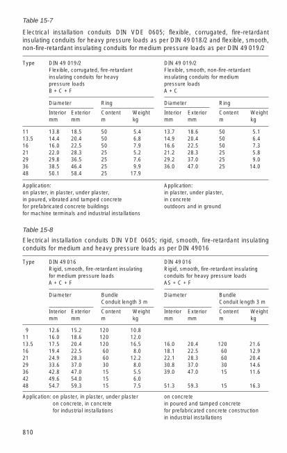
810
Table 15-7
Electrical installation conduits DIN VDE 0605; flexible, corrugated, fire-retardantinsulating conduits for heavy pressure loads as per DIN 49 018/2 and flexible, smooth,non-fire-retardant insulating conduits for medium pressure loads as per DIN 49 019/2
Type DIN 49 019/2 DIN 49 019/2Flexible, corrugated, fire-retardant Flexible, smooth, non-fire-retardant insulating conduits for heavy insulating conduits for mediumpressure loads pressure loadsB + C + F A + C
Diameter Ring Diameter Ring
Interior Exterior Content Weight Interior Exterior Content Weightmm mm m kg mm mm m kg
11 13.8 18.5 50 5.4 13.7 18.6 50 5.113.5 14.4 20.4 50 6.8 14.9 20.4 50 6.416 16.0 22.5 50 7.9 16.6 22.5 50 7.321 22.0 28.3 25 5.2 21.2 28.3 25 5.829 29.8 36.5 25 7.6 29.2 37.0 25 9.036 38.5 46.4 25 9.9 36.0 47.0 25 14.048 50.1 58.4 25 17.9
Application: Application:on plaster, in plaster, under plaster, in plaster, under plaster,in poured, vibrated and tamped concrete in concretefor prefabricated concrete buildings outdoors and in groundfor machine terminals and industrial installations
Table 15-8
Electrical installation conduits DIN VDE 0605; rigid, smooth, fire-retardant insulatingconduits for medium and heavy pressure loads as per DIN 49016
Type DIN 49 016 DIN 49 016Rigid, smooth, fire-retardant insulating Rigid, smooth, fire-retardant insulatingfor medium pressure loads conduits for heavy pressure loadsA + C + F AS + C + F
Diameter Bundle Diameter BundleConduit length 3 m Conduit length 3 m
Interior Exterior Content Weight Interior Exterior Content Weightmm mm m kg mm mm m kg
9 12.6 15.2 120 10.811 16.0 18.6 120 12.013.5 17.5 20.4 120 16.5 16.0 20.4 120 21.616 19.4 22.5 60 8.0 18.1 22.5 60 12.921 24.9 28.3 60 12.2 22.1 28.3 60 20.429 33.6 37.0 30 8.0 30.8 37.0 30 14.636 42.8 47.0 15 5.5 39.0 47.0 15 11.642 49.6 54.0 15 6.048 54.7 59.3 15 7.5 51.3 59.3 15 16.3
Application: on plaster, in plaster, under plaster on concrete on concrete, in concrete in poured and tamped concrete for industrial installations for prefabricated concrete construction
in industrial installations
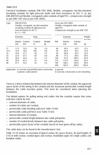
15
811
Table 15-9
Electrical installation conduits DIN VDE 0605, flexible, corrugated, non-fire-retardantinsulating conduits for light pressure loads and heat resistance to 105 °C as per DIN 49019/3 and flexible, corrugated cable conduits of rigid PVC, compressive strengthas per DIN 1187 (not as per VDE 0605)
Type DIN 49 019/3 not as per VDE 0605Flexible, corrugated, non-fire-retardant Flexible, corrugated cable conduits ofinsulating conduits for light pressure rigid PVCHeat resistance to 105 °C Compressive strength as per DIN 1187B + C + 105
Diameter Ring Diameter Weighteach 100 m
Interior Exterior Content Weight NW Interior Exteriormm mm m kg mm mm kg
11 11.5 15.6 50 2.0 40 36.5 42.5 13.213.5 14.0 18.6 100 4.8 50 43.9 50.5 15.016 16.0 21.1 50 3.1 65 58.0 65.5 22.023 22.9 27.7 50 4.6 80 71.5 80.5 30.029 28.4 33.6 25 2.7 100 91.0 100.5 45.036 35.9 41.5 25 4.0 125 115.0 126.0 62.048 47.7 53.5 25 5.5 160 148.5 160.0 90.0
200 182.0 200.0 140.0
Application: in concrete and prefabricated construction in ground in plaster, under plaster in concrete construction as lost sheathing
There is a direct relationship between the internal diameter of the conduit, the approvedspace factor of the wiring in the conduit and the maximum permissible conduit lengthbetween the cable insertion points. This must be considered when planning theinstallation.
The limited options for pulling wiring and cables into the conduits require that someselection criteria be met:– external diameter of cable,– number of cables per conduit, – permissible cable bending radii (see Table 13-64) – permissible cable pull force (see Table 13-63) – internal diameter of conduit,– permissible conduit length between two cable pull points, – number of conduit bends between two cable pull points,– permissible space factor of the conduits based on heat given off by cables.
The cable data can be found in the manufacturers’ lists.
Table 15-10 shows an overview of typical values for space factors, for pull lengths of 3-35 m with various conduit types and various installation types for single cables andbundled cables.

812
Table 15-10
Selection of conduits and conduit filling factor, typical values for space factors withmanual insertion
Approved space factors of conduits with amax. draw length 3 m 6 m 9 m 12 m 20 m 25 m 30 m 35 m
PVC/steel conduit in open conduit installation, single cableDRi = 18 – 44 mm 0.7 0.7 0.5 0.5 — — — —
≥ 45 mm 0.4 0.4 0.4 0.4 0.4 0.4 0.4 —
PVC/steel conduit in open conduit installation, bundled cableDRi = 18 – 44 mm 0.6 0.5 0.4 0.3 — — — —
≥ 45 mm 0.3 0.3 0.3 0.3 0.3 0.3 — —
PVC/steel conduit in closed conduit installation, single cableDRi = 18 – 44 mm 0.4/0.3 0.4/0.3 0.3/0.2 0.3/0.2 — — — —
≥ 45 mm 0.2/0.2 0.2/0.2 0.2/0.2 0.2/0.2 — — — —¹⁄₂ conduit bend
PVC/steel conduit in closed conduit installation, bundled cableDRi = 18 – 44 mm 0.4/0.3 0.4/0.3 0.3/0.2 0.3/0.2 — — — —
≥ 45 mm 0.2/0.2 0.2/0.2 0.2/0.2 0.2/0.2 — — — —¹⁄₂ conduit bend
PVC/concrete conduit in ground or concrete, single cableDRi ≤ 50 mm 0.5 0.5 0.5 0.5 0.5 — — —
> 50 mm 0.4 0.4 0.4 0.4 0.4 0.4 0.4 0.4
PVC/concrete conduit in ground or concrete, bundled cableDRi ≤ 50 mm 0.4 0.4 0.4 0.4 0.4 — — —
> 50 mm 0.3 0.3 0.3 0.3 0.3 0.3 0.3 0.3
DRi = interior conduit diameter (mm)
The effective space factor is calculated from the square of the interior diameter of theconduit (DRi) and the sum of the squares of the external diameter of all cables (Σ DKA
2)that will be pulled into the conduit according to the following formula:
Σ DKA2
Pr = ——— Pr approvedDRi
2
Conduits with an interior diameter of less than 18 mm (in ground and concrete less than50 mm) should generally not be used.
If the cables are pulled in by machine, as is often the case with conduit installations inground or concrete, the max. draw length may not exceed 100 m.

15
813
15.4.3 Lighting installations
Installations for lighting indoor and outdoor switchgear installations and their auxiliaryequipment are subject to very varied requirements regarding intensity of lighting,limiting glare, colour and colour reproduction.
Table 15-11 lists recommendations conforming to ASR 7/3 and DIN 5035 Part 2.
Workplace directive ASR 7/3 and DIN 5035 specify nominal lighting intensities forilluminating workplaces. ASR 7/3 was released by the Federal Minister for Labor andSocial Affairs and therefore forms the legal basis for lighting workplaces.
DIN 5035 Part 3 (hospitals), Part 4 (educational institutions), Part 5 (emergencylighting) and Part 7 (computer workstations) are subject to additional regulations.
Planners of lighting installations should take into consideration that lights become dirtyand that they deteriorate with age. For this reason, a planning factor is calculated intonew installations.
Standard planning factor for contamination and deterioration:1.25 standard,1.43 enhanced,1.67 strong.
These factors are multiplied with the rated value of the required illumination intensity tofind the required installation intensity.
The set rated lighting intensities En are rated values of the average lighting intensity.They must not be below these values. The quality criteria of lighting colour, colourreproduction and limitation of glare are covered in ASR 7/3 and DIN 5035.

814
Table15-11
Lighting with artificial light.Recommendations for various lighting tasks (extracts from ASR 7/3 and DIN 5035 Part 2)
Type of space Rated Light Stages of Quality class or activity lighting colour colour of glare
intensityEn reproduction restrictionIx properties
General spaces
Traffic zones in 50 ww, nw 3 3 storage rooms, warehouses
Warehouses for similar 50 ww, nw 3 3 or large items
Warehouses with search 100 ww, nw 3 3 tasks among dissimilar storage items
Warehouses with 200 ww, nw 3 2 read tasks
Automatic high- 20 ww, nw 3 3 rack warehouses, aisles
Operator station 200 ww, nw 2A 1
Shipping 200 ww, nw 3 2
Lunchrooms, sanitation 200 ww, nw, 2A 1roomsand canteens
Other rest areas 100 ww, nw 2A 1 and sleeping rooms
Changing rooms, 100 ww, nw 2A 2bathrooms, toilets
Sanitation rooms, rooms 500 ww, nw 1A 1 for first aid and medical treatment
Passageways in buildings
For persons 50 ww, nw 3 3
For persons and 100 ww, nw 3 3 vehicles
Stairs, escalators, 100 ww, nw 3 2 inclined passageways
Loading ramps 100 ww, nw 3 3
(continued)
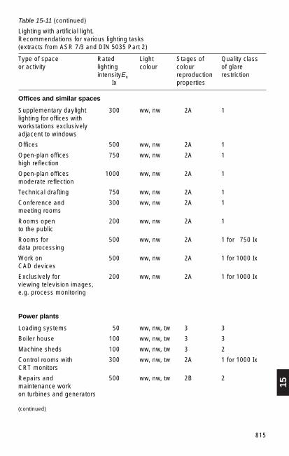
15
815
Table 15-11 (continued)
Lighting with artificial light.Recommendations for various lighting tasks (extracts from ASR 7/3 and DIN 5035 Part 2)
Type of space Rated Light Stages of Quality class or activity lighting colour colour of glare
intensityEn reproduction restrictionIx properties
Offices and similar spaces
Supplementary daylight 300 ww, nw 2A 1 lighting for offices with workstations exclusively adjacent to windows
Offices 500 ww, nw 2A 1
Open-plan offices 750 ww, nw 2A 1 high reflection
Open-plan offices 1000 ww, nw 2A 1 moderate reflection
Technical drafting 750 ww, nw 2A 1
Conference and 300 ww, nw 2A 1 meeting rooms
Rooms open 200 ww, nw 2A 1 to the public
Rooms for 500 ww, nw 2A 1 for 750 Ixdata processing
Work on 500 ww, nw 2A 1 for 1000 IxCAD devices
Exclusively for 200 ww, nw 2A 1 for 1000 Ixviewing television images, e.g. process monitoring
Power plants
Loading systems 50 ww, nw, tw 3 3
Boiler house 100 ww, nw, tw 3 3
Machine sheds 100 ww, nw, tw 3 2
Control rooms with 300 ww, nw, tw 2A 1 for 1000 IxCRT monitors
Repairs and 500 ww, nw, tw 2B 2 maintenance work on turbines and generators
(continued)

816
Table 15-11 (continued)
Lighting with artificial light.Recommendations for various lighting tasks (extracts from ASR 7/3 and DIN 5035 Part 2)
Type of space Rated Light Stages of Quality class or activity lighting colour colour of glare
intensityEn reproduction restrictionIx properties
Switchgear installations – values from in-house experience
Switchgear installations 100 nw 2 2in buildings
Switchgear installations 20 ww, nw 3,4 3outdoors
Control rooms 300 ww, nw 2 1
Electrical engineering industry
Cable and wiring 300 ww, nw, tw 3 1 manufacture, coating and impregnating coils, assembly of large machines, simple assembly work, winding coils and armatures with coarse wire
Assembly of telephone 500 ww, nw, tw 3 1 sets, small motors, winding coils and armatures with medium wire
Assembly of precision 1000 ww, nw, tw 3 1 devices, radio and television equipment, winding fine wire coils, manufacturing fuses, adjusting, testing and calibrating
Assembly of high-precision 1500 ww, nw, tw 2A 1 parts, electronic components
Assembly of high- and very 1000 ww, nw, tw 2 1 for 1500 Ix high-precision parts with CRT monitors

15
817
In addition to the lighting intensity the colour and colour reproduction determine theselection of lights for the required purpose (Table 15-12).
Table15-12
Colour and colour reproduction properties of light sources
Stages of Light colour Typical Remarks Typicalcolour light sources applications reproduction properties
1 daylight xenon lamps, textile industry,white fluorescent lights graphical(tw) (daylight) and halogen commercial,
metal-vapour lamps factory sheds,with very good colour outdoor manu-reproduction facturing halls,properties sales rooms
neutral fluorescent lights can be offices, schools,white (white) with very good combined laboratories, sales(nw) colour reproduction with daylight rooms, art
properties galleries
warm-white incandescent lights, can be mood lighting,(ww) halogen incandescent combined living area,
lights, fluorescent very well with restaurants,lights (warm tone) incandescent sales roomswith very good colour lightsreproductionproperties
2 daylight fluorescent lights factory halls, white (daylight) and halogen exhibition halls(tw) metal-vapour lamps
with good colourreproduction properties
neutral fluorescent lights can be offices, schools,white (white) with good combined laboratories, sales(nw) colour reproduction with daylight rooms, show
properties window, industrialcommercial workrooms
warm-white fluorescent lights can be hallways, stairwells(ww) (warm tone) with good combined houses, lighting
colour reproduction well with outdoorsproperties incandescent
lights

818
Table 15-12 (continued)
Colour and colour reproduction properties of light sources
Stages of Light colour Typical Remarks Typicalcolour light sources applicationsreproduction properties
3 neutral fluorescent lights can be industrial and white (white) with few combined commercial (nw) good colour with daylight work rooms,
reproduction properties, lighting outdoors mercury vapourhigh-pressure lamps with fluorescent material, mixed lamps
warm-white fluorescent lights warehouses (ww) (warm tone) with few lighting outdoors
good colour reproductionproperties
4 sodium-vapour lamps floodlighting, mercury vapour lighting outdoorshigh-pressure lampswithout fluorescent material
Three quality classes are distinguished with very individual criteria with therequirements for the glare limitation:
Quality class 1: high demands, ca. 10 % of persons surveyed still detect distractingglare.
Quality class 2: moderate demands, ca. 30 % of persons surveyed still detectdistracting glare.
Quality class 3: low demands, ca. 40 % of persons surveyed still detect distractingglare.
The requirements for a lighting installation are determined by the following criteria:– horizontal lighting intensity, – if applicable, vertical lighting intensity, – even lighting distribution,– limitation of glare,– colour reproduction stage.
The following must also be considered:– room dimensions,– colour of the reflecting surfaces around the outside of the room,– mounting height above working plane.

15
819
The vertical lighting intensity is significant where vertically mounted instruments anddevices need to be continuously monitored.
Refer to the “Manual for Lighting”, published by the “technical lighting associations(Lichttechnischen Gesellschaften)” and “working group (Arbeitsgemeinschaft)” ofSwitzerland, Austria and Germany, for descriptions of the calculation procedures. Anexplanation of the two calculation procedures is given there as follows:– efficiency method
and – point calculation method.
The point calculation method is generally recommended for outside lighting systemsand for demanding interior applications (such as control rooms, network control rooms).
The efficiency method is generally sufficiently accurate for offices and workshops,switchgear rooms and access passages.
The requirements for lighting emergency and escape paths are described in DIN 5035Part 5. The Workplace Directive ASR 7/4 “Emergency Lighting” must also be taken intoaccount.
15.4.4 Fire alarm systems
Fires can occur even in installations that are protected by structural measures.
An important component of preventive fire protection (see Section 4.7.6) is fire alarmequipment that is automatically or manually activated in accordance with DIN VDE0833 Parts 1+2. Both the directives of the VdS (association of property insurers) andthe structural fire regulations must be observed.
If a fire can be detected early and action to extinguish it taken quickly and directly, thedamage caused by the fire or the process of extinguishing it can be reduced.
Automatic fire alarm systems are recommended for switchgear installations, controlrooms and data processing systems that are not continuously staffed.
Switchgear installations supplying hospitals and other critical installations must beequipped with fire alarm systems or be included in the general fire alarm system.
Fire alarms are forwarded to a central monitoring site. An incoming fire alarmautomatically initiates the appropriate firefighting measures. Fig. 15-15 shows a circuitdiagram of an automatically or manually actuated alarm system.
Smoke, temperature or the optical appearance of flames are the quantities for earlydetection of fires that set off the alarm when maximum values are exceeded. Thesealarms actuate stationary extinguishing systems and also alert the fire departmentthrough a central monitoring system.

820
A fire alarm system generally consists of the following components– automatic fire alarms (heat, smoke, flames) installed in groups,– central fire alarm,– secure power supply from power system or battery,– alarm equipment such as sirens, horns, flashing lights,– actuation, tripping,– transmission equipment for fire alarms to a continuously staffed monitoring centre
(fire department),– non-automatic manual alarms for less important areas.
The design of an automatic fire alarm system should also include any existing air intakeand exhaust systems (corresponding placement of the spot alarms, otherwise an alarmmay be delayed).
1 Central fire alarm,1a Power supply (power system and battery)2 Automatic fire detectors3 Non-automatic fire alarm (manual alarm)4 Alarms and actuation/tripping5 Plant fire department6 Building services (fault alarms)7 Transmission equipment for
fire alarms (main fire alarm)8 Public fire department8a Fire department control panel8b Fire department key compartment
Fig.15-15
Circuit diagram of a fire alarmsystem
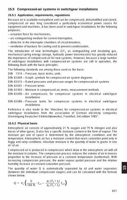
15
821
15.5 Compressed-air systems in switchgear installations
15.5.1 Application, requirements, regulations
Because air is available everywhere and can be compressed, dehumidified and stored,compressed air was long considered a particularly economical power source forequipment and machines. It has been used in switchgear installations for the followingpurposes:– actuation force for mechanisms,– arc-extinguishing medium for current interruption,– dielectric in the interrupter chambers of circuit-breakers,– ventilation of busbars for cooling and to prevent condensation.
The introduction of new technologies (SF6 as extinguishing and insulating gas,mechanical spring energy storage, hydraulic power transmission) has greatly reducedthe importance of compressed air for new systems. However, because a large numberof switchgear installations with compressed-air systems are still in operation, thefollowing deals with the basic principles.
The following standards are among those used as the basis:DIN 1314 – Pressure, basic terms, unitsDIN 43 609 – Graph. symbols for compressed-air system diagramsDIN 43 615 – Rated pressures and pressure ranges for compressed-air systemsDIN 43 691 – Pressure termsDIN 43 903 – Moisture in compressed air, terms, measurement methodsDIN 43 690 – Air compressors for compressor systems in electrical switchgear
installationsDIN 43 686 – Pressure tanks for compressor systems in electrical switchgear
installations
Reference is also made to the “directives for compressed-air systems in electricalswitchgear installations from the association of German electricity companies(Vereinigung Deutscher Elektrizitätswerke), Frankfurt, 3rd edition 1985”.
15.5.2 Physical basis
Atmospheric air consists of approximately 21 % oxygen and 79 % nitrogen and alsotraces of other gases. It also has a specific moisture content in the form of vapour. Themoisture per unit of space is determined by the atmospheric conditions and thetemperature. Atmospheric air has a moisture content that nears saturation point only infoggy and rainy conditions. Absolute moisture is the quantity of water in grams in onem3 of air.
Compressed air is produced in compressors which draw in the atmospheric air with allthe moisture it contains. The compression process reduces the volume of air in inverseproportion to the increase of pressure at a constant temperature (isothermal). Withincreasing compression pressure, the water vapour partial pressure and the relativehumidity increase at constant saturation pressure.
The quantity of water Q is automatically separated by oil and water separators(between the individual compression stages) and can be calculated with the formulashown below.
U p1 (T0 + t2)Q = Va (——— · fsn1 – ———–— · fsn2)100 % p2 (T0 + t1)

822
The following letters are used:
fsn1 maximum possible moisture content at intake temperature t1 (g/l), fsn2 maximum possible moisture content at discharge temperature t2 (g/l), Va volume of intake air (I/min), U relative humidity (%), p1 pressure of intake air (bar), p2 pressure of compressed air (bar), t1 temperature of intake air (°C), t2 temperature of compressed air (°C).
Example:
Va = 500 I/min, p1 = 1 bar, p 2 = 200 bar, t1 = + 10 °C, according to Table 15-13: fsn1 = 0.0094 g / l, t2 = + 25 °C, according to Table 15-13: fsn2 = 0.023 g/ l, U = 60 %. Q = ?
Separated water:
I 60% g 1 bar (273 + 25) K g gQ = 500 –— (—–— · 0.0094 — – ———— · —————— · 0.023 —)= 2.76 ——
min 100% l 200 bar (273 + 10) K l min
Water separators in the compressor only removed the condensed water in thecompressed air but not the moisture content in the form of vapour. If compressed air isto be used to actuate switchgear, the moisture content must be reduced. This isgenerally done by reducing the pressure and cooling the pressure tanks, or if this is notsufficient, by using air dryers.
The requirements for air quality regarding moisture content vary for indoor and outdoorinstallations. A moisture reduction to 40 % is sufficient for indoor installations but air-blast breakers for outdoor installations require a reduction to ca. 15 . . . 20 % to go belowthe dew point and thereby to prevent condensation in the switching device. In general,this means a pressure-reduction ratio of 5:1. This reduction ratio assures protectioneven in case of a fall in temperature of ca. 20 K over the temperature range –35 °C ...+50 °C. As can be seen in Table 15-13, even at low temperatures the air contains asmall quantity of moisture. Air heated by compression should therefore be cooled to theambient temperature of the switchgear if at all possible.

15
823
Fig. 15-16
Saturated moisture content of compressed air
Table 15-13
Water content of air at various temperatures for standard pressure pn (atmosphericpressure)
Dew point Saturationtemperature moisturefsn
° C g/m3 ° C g/m3 ° C g/m3
– 30 0.33 + 15 6.790 + 35 39.286– 20 0.88 + 10 9.356 + 40 50.672– 15 1.38 + 15 12.739 + 45 64.848– 10 2.156 + 20 17.148 + 50 82.257– 15 3.230 + 25 22.830
0 4.860 + 30 30.878
Definitions of some important compressed air quantities:
f = absolute moisture content, in g/m3 or ppm, the quantity of moisture present at aspecified temperature
fsn = saturated moisture content, in g/m3 or ppm, is the maximum quantity of watervapour that can be absorbed by one m3 of dry air at atmospheric pressure
fs = saturation moisture content of compressed air, in g/m3 or ppm, is dependent ontemperature and pressure
Compression pressure p
Fig. 15-16 shows the relationship between saturated moisture content fs, pressure dewpoint tpd and compression pressure p.
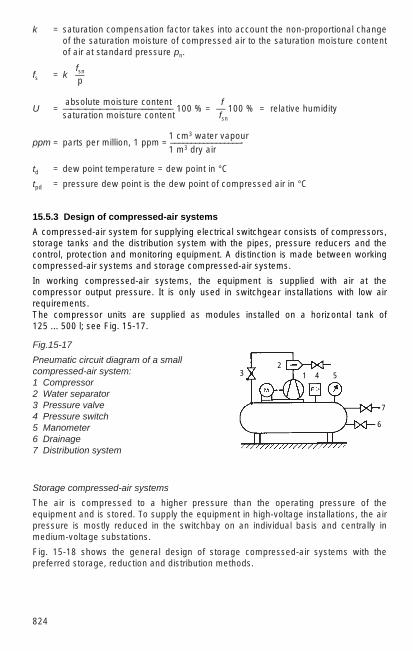
k = saturation compensation factor takes into account the non-proportional changeof the saturation moisture of compressed air to the saturation moisture contentof air at standard pressure pn.
fsnfs = k · —p
absolute moisture content fU = ————————––––––––––––––– 100 % = — 100 % = relative humidity
saturation moisture content fsn
1 cm3 water vapourppm = parts per million, 1 ppm = –––––––––––––––––-
1 m3 dry air
td = dew point temperature = dew point in °C
tpd = pressure dew point is the dew point of compressed air in °C
824
Storage compressed-air systems
The air is compressed to a higher pressure than the operating pressure of theequipment and is stored. To supply the equipment in high-voltage installations, the airpressure is mostly reduced in the switchbay on an individual basis and centrally inmedium-voltage substations.
Fig. 15-18 shows the general design of storage compressed-air systems with thepreferred storage, reduction and distribution methods.
Fig.15-17
Pneumatic circuit diagram of a smallcompressed-air system:1 Compressor2 Water separator3 Pressure valve4 Pressure switch5 Manometer6 Drainage7 Distribution system
15.5.3 Design of compressed-air systems
A compressed-air system for supplying electrical switchgear consists of compressors,storage tanks and the distribution system with the pipes, pressure reducers and thecontrol, protection and monitoring equipment. A distinction is made between workingcompressed-air systems and storage compressed-air systems.
In working compressed-air systems, the equipment is supplied with air at thecompressor output pressure. It is only used in switchgear installations with low airrequirements. The compressor units are supplied as modules installed on a horizontal tank of 125 ... 500 l; see Fig. 15-17.
23
7
6
541

15
825
15.5.4 Rated pressures and pressure ranges
Compressed air generating and distribution systems for specialized applicationsconsist of compressor, storage, reduction equipment and distribution. Table 15-14shows an overview of the pressure ranges of the various sections of the system.
Table 15-14
Rated pressures and pressure ranges for compressed-air systems as per DIN 43 615
Rated Compression Storage Distribution Rated breakerpressure pressure1) pressure pressure pressurebar bar bar bar bar
10 5… 10 5… 1040 25 2564 30… 44 30… 44 5, 15, 20, 5, 15, 20,64 60… 64 60… 64 40, 60, 160, 25, 30, 35100 100…120 100…120 200250 200…250 170…200
1) The compressor pressure may be higher when pressure valves are used.
The selection of pressure levels depends largely on the breaker operating pressure, airrequirements, required storage volume, repressurizing times and the permissiblemoisture in the breaker tank. To meet all possible daily and seasonal temperaturevariations, pressure levels must be selected to ensure that no condensation occurs inthe breaker tank or in the interior of the breaker at even the maximum possible fall intemperature. Fig. 15-19 shows an overview of the connections between the airtemperature t, fall in temperature ∆ t and the expansion ratio ε.
Fig.15-18
Storage compressed-air systems, schematic design:
a) central reduction to breaker pressure b) local reduction, storage at distribution pressure.c) central/local reduction, storage at high pressure and distribution pressure.
1 Compressor, 2 Pressure valve, 3 Combined line for compression, 4 Storage tank (high-pressure), 5 Pressure reduction valve, 6 Combined line for distribution, 7 Storage tank (distribution pressure), 8 Storage tank (operating pressure), 9 Tanks at the switching device
Compression
Storage
Distribution
b)a) c)
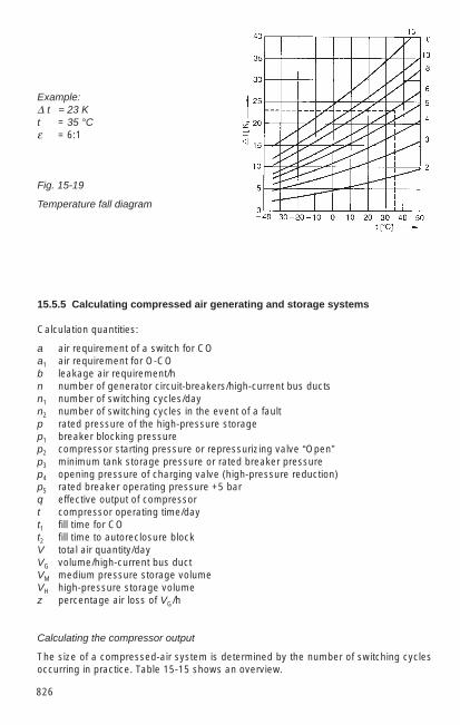
826
Example:∆ t = 23 K t = 35 °C ε = 6:1
Fig. 15-19
Temperature fall diagram
15.5.5 Calculating compressed air generating and storage systems
Calculation quantities:
a air requirement of a switch for CO a1 air requirement for O-CO b leakage air requirement/h n number of generator circuit-breakers/high-current bus ductsn1 number of switching cycles/dayn2 number of switching cycles in the event of a faultp rated pressure of the high-pressure storagep1 breaker blocking pressurep2 compressor starting pressure or repressurizing valve “Open”p3 minimum tank storage pressure or rated breaker pressurep4 opening pressure of charging valve (high-pressure reduction) p5 rated breaker operating pressure +5 bar q effective output of compressor t compressor operating time/day t1 fill time for CO t2 fill time to autoreclosure block V total air quantity/dayVG volume/high-current bus duct VM medium pressure storage volume VH high-pressure storage volumez percentage air loss of VG/h
Calculating the compressor output
The size of a compressed-air system is determined by the number of switching cyclesoccurring in practice. Table 15-15 shows an overview.

15
827
Table 15-15
Switching cycles of circuit-breakers, typical values
Number of circuit-breakers power plant, transformer substationwhen fully installed in 10 ... 30 kVthe installation Number of switching cycles:
in 24 h immediately on faults
n n1 n2
1 2 12 5 24 9 46 11 68 13 8
10 15 9
The compressor output is derived as follows:
n1 · a + n · bq = ——————
t
For switchgear “b” takes the leakage losses over 24 hours into account. They areincluded in the circuit-breaker datasheets.
z · VG · 24With high-current bus ducts b = —————––
100
The storage volume of the compressed-air systems is calculated for medium- and high-pressure storage as follows:
Medium- and high-pressure storage
2 n2 · aVH = ———––––—
3 (p2 – p3)
n2 · aVM = ———––––—
3 (p4 – p5)
If high-pressure storage only is used, then
n2 · aVH = ——––—
p2 – p3

828
15.5.6 Compressed air distribution systems
Copper and steel pipes are used for the compressed air distribution system. The jointsare designed with soldered fittings for an operating pressure of up to 60 bar. A softsolder with 95% Sn + 5% Sb is used for copper pipes at a working temperature ofapproximately 245 °C.
A hard solder with 40% Ag can be used for applications with severe mechanicalstresses. Because the melting point of this solder is over 600 °C, the pipes are heatedduring soldering. They must therefore only be stressed with the load value of the nextlower strength class of the soft state.
At an operating pressure of over 60 bar, cutting ring screws as per DIN 43685 or 2353are generally used.
The lines between the compressor system and the switchgear are either radial lines orring lines, depending on the size of the system.
Copper pipes with external diameters of 6, 8, 10, 12, 18, 20 and 28 mm and steel pipesof 6, 8, 10 and 12 mm are used.
The wall thickness and pressure ranges of the compressed air lines in switchgearinstallations are specified in DIN 43614.
Changes in the length of the pipes caused by changes in temperature must becompensated by installing expansion loops. Pipes must be able to move slightly wheninstalled.

16
829
16 Materials and Semi-Finished Products forSwitchgear Installations
16.1 Iron and steel
16.1.1 Structural steel, general
The material specifications for structural steels to DIN EN 10 029 apply to carbon steelsand low-alloy steels: these are used in the hot-worked condition, and to a lesser extentafter normalizing, for reasons of tensile strength and yield strength. The specificationsare also valid for forgings, section steel, strip, and heavy and medium plates made fromthese steels. This standard DIN EN 10 029 does not apply to the products given inTable 16-2.
Weldability is better with low-carbon steels having less than 0.22% C. Weldability isbest with steels of grade 3, e.g. St 37-3 (S235 JR), and poorest with steels of grade 1.Killed steels are to be preferred to rimmed steel, especially if segregation zones mightbe encountered when welding.
Identification codes for structural steels are contained in DIN EN 10027. This alsoshows the chemical composition and method of melting or casting.
The standards giving the dimensions of general structural steels are listed in Table16-1.
Table 16-1
Dimensional standards
Round steel, general purpose DIN 1013Square steel DIN 1014Flat steel, general purpose DIN 1017Equal angle section and deep-web T bars, square edge DIN 1022T bars, round edge DIN EN 10055I bars and I beams DIN 1025Channel bars and beams DIN 1026Steel angle DIN 1028Steel angle, unequal widths DIN 1029Steel sheet less than 3 mm (thin sheet) DIN EN 10131Steel sheet 5 mm and above (heavy plate) DIN EN 10130
Table 16-2
Dimensional standards
Steel for screws, bolts and nuts DIN 1654, DIN 17 240, DIN 59 130Heat-treatable steel DIN EN 10 083Case-hardening steel DIN 17 210Thin sheet less than 3 mm thick DIN 1623, Sheet 1 and DIN EN 10 130Identification code for surface type and treatment (DIN 1623)

830
16.1.2 Dimensions and weights of steel bars, sections and tubes
Table 16-3
Dimensions and weight of steel bars
Square and flat steel DIN 1014/1017
Dimensions Cross-section Weight Dimensions Cross-section Weightmm cm2 kg/m mm cm2 kg/m
18 × 4 0.32 0.24910 × 5 0.5 0.39012 × 5 0.6 0.470
13 × 2.5 0.325 0.25515 × 5 0.75 0.595 1
20 × 3 0.6 0.47120 × 4 0.8 0.624 120 × 5 1.0 0.780 120 × 8 1.6 1.26 1
25 × 3 0.75 0.589 125 × 4 1.0 0.785 125 × 5 1.25 0.981 1
26 × 21) 0.52 0.408
30 × 3 0.9 0.705 130 × 3.51) 1.05 0.825 130 × 4 1.2 0.936 130 × 5 1.5 1.17030 × 30 9.0 7.065 1
35 × 3 1.05 0.825 135 × 4 1.4 1.09 135 × 5 1.75 1.3635 × 35 12.25 9.62
40 × 3 1.2 0.94240 × 41) 1.6 1.2640 × 5 2.0 1.5640 × 6 2.4 1.87
1) also galvanized for earth conductors
Earthing plate 1000 · 1000 · 3 mm with strip 2.5 m long, approx. 30 kgEarth rod 1" diameter, 2000 mm long, 5.3 kgEarth rod 2" diameter, 3000 mm long, 16.5 kg
140 × 18 3.2 2.50140 × 10 4.0 3.12140 × 40 16.0 12.60
145 × 15 2.25 1.75145 × 18 3.6 2.81145 × 10 4.5 3.51
150 × 13 1.5 1.17150 × 14 2.0 1.56150 × 15 2.5 1.95150 × 16 3.0 2.34150 × 18 4.0 3.12150 × 10 5.0 3.90
160 × 15 3.0 2.34160 × 18 4.8 3.74160 × 10 6.0 4.68
165 × 15 3.25 2.53
180 × 15 4.0 3.12180 × 16 4.8 3.74180 × 18 6.4 4.99180 × 10 8.0 6.24
100 × 15 5.0 3.90100 × 16 6.0 4.68100 × 18 8.0 6.24100 × 10 10.0 7.8
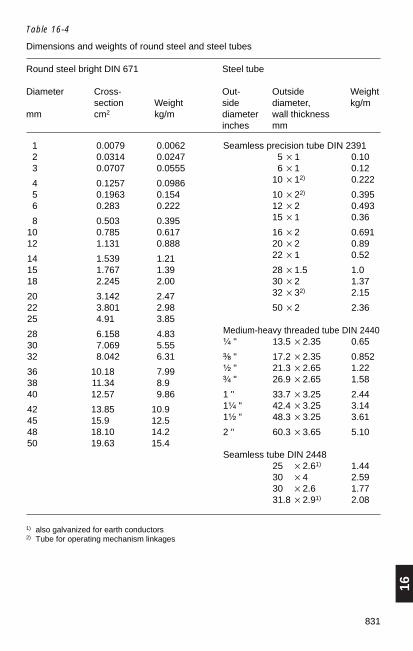
16
831
Table 16-4
Dimensions and weights of round steel and steel tubes
Round steel bright DIN 671 Steel tube
Diameter Cross- Out- Outside Weightsection Weight side diameter, kg/m
mm cm2 kg/m diameter wall thicknessinches mm
Seamless precision tube DIN 23915 × 1 0.106 × 1 0.12
10 × 12) 0.222
10 × 22) 0.39512 × 2 0.49315 × 1 0.36
16 × 2 0.69120 × 2 0.8922 × 1 0.52
28 × 1.5 1.030 × 2 1.3732 × 32) 2.15
50 × 2 2.36
Medium-heavy threaded tube DIN 2440¹⁄₄ " 13.5 × 2.35 0.65
³⁄₈ " 17.2 × 2.35 0.852¹⁄₂ " 21.3 × 2.65 1.22³⁄₄ " 26.9 × 2.65 1.58
1 " 33.7 × 3.25 2.441¹⁄₄ " 42.4 × 3.25 3.141¹⁄₂ " 48.3 × 3.25 3.61
2 " 60.3 × 3.65 5.10
Seamless tube DIN 244825 × 2.61) 1.4430 × 4 2.5930 × 2.6 1.7731.8 × 2.91) 2.08
1 0.0079 0.00622 0.0314 0.0247 3 0.0707 0.0555
4 0.1257 0.09865 0.1963 0.1546 0.283 0.222
8 0.503 0.39510 0.785 0.61712 1.131 0.888
14 1.539 1.2115 1.767 1.3918 2.245 2.00
20 3.142 2.4722 3.801 2.9825 4.91 3.85
28 6.158 4.8330 7.069 5.5532 8.042 6.31
36 10.18 7.9938 11.34 8.940 12.57 9.86
42 13.85 10.945 15.9 12.548 18.10 14.250 19.63 15.4
1) also galvanized for earth conductors2) Tube for operating mechanism linkages

832
Table 16-5
Steel angle
Equal width DIN 1208 Unequal width DIN 1029Symbol Weight Section Symbol Weight SectionL modulus L modulusa × s a × b × s Wx Wymm kg/m cm3 mm kg/m cm3 cm3
20 × 3 0.88 0.28 30 × 20 × 4 1.45 0.81 0.3825 × 3 1.12 0.45 40 × 20 × 3 1.35 10.8 0.3025 × 4 1.45 0.58 40 × 20 × 4 1.77 1.42 0.39
30 × 3 1.36 0.65 45 × 30 × 4 2.25 1.91 0.9130 × 4 1.78 0.86 45 × 30 × 5 2.77 2.35 1.1135 × 4 2.10 1.18 60 × 30 × 5 3.37 4.04 1.12
40 × 4 2.24 1.56 60 × 30 × 7 4.59 5.50 1.5240 × 5 2.97 1.91 50 × 40 × 5 3.36 3.20 2.0145 × 5 3.38 2.43 60 × 40 × 5 3.76 4.25 2.02
50 × 5 3.77 3.05 60 × 40 × 6 4.46 5.03 2.3850 × 6 4.47 3.61 80 × 40 × 6 5.41 8.73 2.4455 × 6 4.95 4.40 80 × 65 × 8 8.66 12.3 8.41
60 × 6 5.42 5.29 65 × 50 × 5 4.35 5.11 3.1860 × 8 7.09 6.88 65 × 50 × 7 5.97 6.99 4.3165 × 7 6.83 7.18 100 × 50 × 6 6.85 13.08 3.86
65 × 9 8.62 9.04 100 × 50 × 8 8.99 18.0 4.0570 × 7 7.38 8.43 90 × 60 × 6 6.82 11.7 5.6170 × 9 9.34 10.6 90 × 60 × 8 8.96 15.4 7.31
75 × 8 9.03 11.0 80 × 65 × 6 6.60 9.41 6.4480 × 8 9.66 12.6 80 × 65 × 8 8.66 12.3 8.4180 × 10 11.9 15.5 100 × 65 × 7 8.77 16.6 7.54
90 × 9 12.2 18.0 100 × 65 × 9 11.1 21.0 9.5290 × 11 14.7 21.6 100 × 75 × 9 11.8 21.5 12.7
100 × 10 15.1 24.7 120 × 80 × 10 15.0 34.1 16.2
100 × 12 17.8 29.2 130 × 65 × 10 14.6 38.4 10.7110 × 10 16.6 30.1 130 × 90 × 10 16.6 40.5 20.6120 × 11 19.9 39.5 150 × 75 × 11 18.6 56.6 15.9
140 × 13 27.5 63.3 150 × 100 × 10 19.0 54.1 25.9150 × 14 31.6 78.2 150 × 100 × 14 26.1 74.1 35 2150 × 15 36.2 95.6
Steel angle, square edge30 × 3.5 1.55 L section 121 30 × 16 × 4 1.32 L section 18040 × 4 2.39 L section 124 45 × 30 × 4 2.23 L section 203
60 × 40 × 5 3.73 L section 218
Permissible tolerance up to 50 mm ± 1 mm, up to 100 mm ± 1.5 mm, above ± 2 mm.

16
833
For other angle sections, see:DIN 1022, DIN 1028, DIN 1029,DIN 59 370.
Table 16-6
T bars, normal lengths 3 to 12 m, DIN 1024
Symbol Dimensions in mm Weight Section modulus forbending axisx – x y – yWx Wy
b h s = t kg/m cm3 cm3
T Deep-web T bar DIN EN 10 055
120 20 20 3 0.88 0.27 0.20125 25 25 3.5 1.29 0.49 0.34130 30 30 4.0 1.77 0.80 0.58
135 35 35 4.5 2.33 1.23 0.90140 40 40 5 2.96 1.84 1.29145 45 45 5.5 3.67 2.51 1.78
150 50 50 6 4.44 3.36 2.42160 60 60 7 6.23 5.48 4.07170 70 70 8 8.32 8.79 6.32
180 80 80 9 10.7 12.8 9.25190 90 90 10 13.4 18.2 13.0100 100 100 11 16.4 24.6 17.7
TB Broad-flange T bar DIN EN 10 055
130 60 30 5.5 3.64 1.11 2.87135 70 35 6.0 4.66 1.65 4.31140 80 40 7.0 6.21 2.50 7.13
150 100 50 8.5 9.42 4.78 13.5160 120 60 10 13.4 8.09 22.8
T Square-edge T bar
16/16 16 16 2.5 0.58 Mannstädt I 59620/30 30 20 3.0 1.11 Mannstädt I 496625/35 35 25 3.5 1.55 Mannstädt I 398125/38 38 25 3 1.41 Mannstädt I 4981
Tolerances: up to 50 mm ±1 mm, up to 100 mm ±1.5 mm.

834
Symbol Dimensions in mm Weight Section modulus forbending axisx – x y – yWx Wy
h b s t kg/m cm3 cm3
I I beams DIN 1025, Sheet 1
180 180 42 3.9 5.9 5.94 19.5 3.00100 100 50 4.5 6.8 8.34 34.2 4.88120 120 58 5.1 7.7 11.1 54.7 7.41
140 140 66 5.7 8.6 14.3 81.9 10.7160 160 74 6.3 9.5 17.9 117.0 14.8180 180 82 6.9 10.4 21.9 161.0 19.8
200 200 90 7.5 11.3 26.2 214.0 26.0220 220 98 8.1 12.2 31.1 278.0 33.1240 240 106 8.7 13.1 36.2 354.0 41.7
260 260 113 9.4 14.1 41.9 442.0 51.0280 280 119 10.1 15.2 47.9 542.0 61.2300 300 125 10.8 16.2 54.2 653.0 72.2
320 320 131 11.5 17.3 61.0 782.0 84.7340 340 137 12.2 18.3 68.0 923.0 98.4360 360 143 13 19.5 76.1 1090.0 114.0
380 380 149 13.7 20.5 84.0 1260.0 131.0400 400 155 14.4 21.6 92.4 1460.0 149.0
Height tolerances: up to 200 mm ± 2 mm, above ± 3 mm.
Table 16-7
I beams, normal length 4 to 15 m, DIN 1025 Sheet 1

16
835
Symbol Dimensions in mm Weight Section modulus forbending axisx – x y – yWx Wy
h b s t r1 kg/m cm3 cm3
IPB IPB beams DIN 1025, Sheet 2
100 100 100 6.5 10 10 21 89.3 33.4120 120 120 7 11 11 28 144 52.9
140 140 140 8 12 12 36 217 78.6160 160 160 9 14 14 47 329 120180 180 180 9 14 14 53 426 151200 200 200 10 16 15 66 595 214
220 220 220 10 16 15 73 732 258240 240 240 11 18 17 89 974 346260 260 260 11 18 17 97 1160 406280 280 280 12 20 18 116 1 480 523300 300 300 12 20 18 124 1 720 600
320 320 300 13 22 20 138 2 020 661340 340 300 13 22 20 140 2 170 661360 360 300 14 24 21 153 2 510 721380 380 300 14 24 21 156 2 680 721400 400 300 14 26 21 168 3 030 781
425 425 300 14 26 21 170 3 270 781450 450 300 15 28 23 186 3 740 841475 475 300 15 28 23 189 4 010 841500 500 300 16 30 24 204 4 530 902
550 550 300 16 30 24 211 5 100 902600 600 300 17 32 26 232 6 030 962650 650 300 17 32 26 239 6 670 962
700 700 300 18 34 27 259 7 720 1020750 750 300 18 34 27 267 8 430 1020800 800 300 18 34 27 274 9 160 1020
900 900 300 19 36 30 305 11 250 10801000 1000 300 19 36 30 321 12 900 1080
Table 16-8
Wide flange beams with parallel flanges and normal web,DIN 1025 Sheet 2

836
Table 16-9
Steel channel, normal lengths 4 to 15 m, DIN 1026
Symbol Dimensions in mm Weight Section modulus forbending axisx – x y – yWx Wy
1h 1b s 1t kg/m cm3 cm3
U Channel DIN 1026
30 30 33 5 7 4.27 4.26 2.681140 × 20 40 20 5 5.5 2.87 3.79 0.86
40 40 35 5 7 4.87 7.05 3.08
1150 × 25 50 25 5 6 3.86 6.73 1.4850 50 38 5 7 5.59 10.6 3.7560 60 30 6 6 5.07 10.5 2.16
65 65 42 5.5 7.5 7.09 17.7 5.0780 80 45 6 8 8.64 26.5 6.36
100 100 50 6 8.5 10.6 41.2 8.49
120 120 55 7 9 13.4 60.7 11.1140 140 60 7 10 16.0 86.4 14.8160 160 65 7.5 10.5 10.5 116.0 18.3
180 180 70 8 11 22.0 150 22.4200 200 75 8.5 11.5 25.3 191 27.0220 220 80 9 12.5 29.4 245 33.6
240 240 85 9.5 13 33.2 300 39.6260 260 90 10 14 37.9 371 47.7280 280 95 10 15 41.8 448 57.2300 300 100 10 16 46.2 535 67.8
U Square-edge channel
1 600 33 33 2.75 2.75 2.021 440 50 30 4 4 3.23 744 60 30 3 3 2.684 631 120 24 4 4 5.06
Height tolerances: up to 65 mm ± 1.5 mm, up to 200 mm ± 2.0 mm, above ± 3.0 mm.

16
837
16.1.3 Stresses in steel components
The permissible stresses in steel components for transmission towers and structuresfor outdoor switchgear installations are laid down in DIN VDE 0210, Table 9. Values fordifferent kinds of stress, such as tensile, shear, compressive and bearing stresses arespecified for the steel sections given in DIN VDE 0210, 8.4.2.
Permissible stresses:
mechanical engineering materials, cf. “Hütte”, 29th edition, and “Stahlschlüssel”, 15th edition,structural steel, cf. DIN 18800, Part 1structural aluminium, cf. DIN 4113, Part 1.
Remarks:
Structural steels to DIN EN 10 025, screws and bolts to DIN 267. Permissible weldstresses for welded towers are given in DIN 18800, Part 1.
According to VDE 0210, structural steels of grade St 37-2 (S 235 JR) and above maybe used for overhead power lines.
16.2 Non-ferrous metals
16.2.1 Copper for electrical engineering
Cathode copper is covered by DIN EN 1976 and DIN EN 1978. Semi-finished products,such as sheet, strip, tubes, rods, wire and cast and extruded sections, are covered byDIN 1787. Semis of electrical copper must conform to the specifications of DIN 40500.Oxygen-free copper (SE-Cu) is used to meet special requirements regardingformability, for gas welding or for flame soldering.
The identification code is important for ensuring conductivity, composition and strengthcharacteristics.
Example: Identification code
E- Cu F30
Electrical copper (not for gas welding)
Material copper
Tensile strength Rm = 300 N/mm2
For special properties as conductor material, see Section 13.1.1.
16.2.2 Aluminium for electrical engineering
High-purity aluminium, denoted Al 99.99 R, is obtained direct from primary aluminiumor aluminium returns by metallurgical means, cast into ingots at the smelting plant andmarked.
Primary aluminium, denoted Al 99.8 H, is aluminium obtained from the smeltingprocess which conforms to the specified purity.

838
Aluminium for electrical engineering is available as:
1. Pure aluminium to DIN EN 573-2, supplied as primary aluminium (code 99.5 H) orpure aluminium (code 99.5) and unless specified otherwise must not contain morethan 0.03 % Ti + Cr + V + Mn.
2. Wrought aluminium alloys to DIN EN 573-3.
The requirements specified in DIN 40501 and DIN EN 1715 must also be observed.
When ordering, for example, it is important to state the identification code for theconductivity, composition and strength characteristics.
Example: Identification code
E- AlMgSi 0.5 F17
Electrical aluminium
Wrought alloy with 0.5 % Si
Tensile strength Rm = 170 N/mm2
For special properties as conductor material, see Section 13.1.1.
16.2.3 Brass
Information regarding the use of copper-zinc alloys, their composition and types ofsemi-finished products is to be found in DIN 17660.
The corresponding strength properties and the technical terms of delivery are given inthe following standards:
DIN EN 1652 for sheet and strip,DIN EN 12168 for tubes,DIN EN 12163, 12164, 12165 and 12167 for rods,DIN EN 17673 for forgings,DIN EN 12167 and 12168 for extruded sections.
For special properties as conductor material, see Section 13.1.1.

16
839
16.3 Insulating materials
16.3.1 Solid insulating materials
Table 16-10
Abbreviations and properties of solid insulating materials
Abbrevia- Material Density Bending Tensile Impact Elasticity Linear Thermal Max. Tracking Break- Resistivity Dielectric Product labeltion strength strength strength modulus thermal conductivity tempera- resistance down field constant
expansion ture strengthDIN DIN DIN ISO DIN DIN DIN DIN DIN IEC DIN IEC DIN IEC IEC53479 53452 53455 180/C 53457 53328 52612 53458 60112 60243-2 60093 60250ρ σb σz an E α 1 λ °C Comparative Ed ρ D εr (50 Hz)kg/dm3 MPa MPa kJ/m2 MPa 10–4/K W/(m · K) figure kV/mm Ω · cm
Insulating materialsfor cables and conductors
PVC-P polyvinyl chloride 1.3 1 150 1 – 2 0.2 160 600 10 – 25 1015 3.5 – 7.5 Astralon, Mipolam, non-rigid Trovidur
PVC-U polyvinyl chloride rigid 1.38 100 50 30 2 500 1.0 0.2 190 600 30 – 40 1015 3.3 – 4 Vestolit, Vinoflex, ˇˇˇˇˇˇˇˇDC-Fix, Pegulan, HostalitFibres: PW, Rhovyl,Thermovyl
PE high-pressure 0.917 180 12 without 1 100 1.8 0.3 180 600 40 1017 2.25 Lupolen H, Vestolen,polyethylene rupture Trolenlow-pressure 0.96 180 25 without 1 400 2.0 0.5 195 600 45 1017 2.3 Hostalen, Marlexpolyethylene rupture Foils: Baulen, Hellaflex
Fibres: Polytrene, Trofil
XLPE cross-linked without 2.5 130 600 >45 1017 2.4 Cable insulation (XLPE)(VPE) polyethylene rupture
(continued)

840 Table 16-10 (continued)Abbreviations and properties of solid insulating materials
Abbrevia- Material Density Bending Tensile Impact Elasticity Linear Thermal Max. Tracking Break- Resistivity Dielectric Product labeltion strength strength strength modulus thermal conductivity tempera- resistance down field constant
expansion ture strengthDIN DIN DIN ISO DIN DIN DIN DIN DIN IEC DIN IEC DIN IEC IEC53479 53452 53455 180/C 53457 53328 52612 53458 60112 60243-2 60093 60250ρ σb σz an E α 1 λ °C Comparative Ed ρ D εr (50 Hz)kg/dm3 MPa MPa kJ/m2 MPa 10–4/K W/(m · K) figure kV/mm Ω · cm
Insulating materials for foils,semi-finished products, struct. comp.(thermoplastics, mouldings)
PC polycarbonate 1.2 75 65 without 12 200 0.6 0.2 130 275 25 1015 3.0 Lexan, Makrolon(PC 300) rupture
PTFE polytetrafluorethylene 2.2 19 20 without 14 000 0.6 0.24 250 600 35 >1018 2.0 Teflon, Hostaflon TE,rupture Fluon
PS polystyrene 1.05 100 22 12 000 0.8 0.14 60-90 375- 50 >1016 2.5 Polystyrol, Styroflex,475 Novodur,Trolitul, Styron,
VestyronFoils: Trolit, Elektroiso.
foam polystyrene 0.02– 0.3-2.5 0.3-5.5 Styropor0.06
PET polyethylene 1.38 117 54 without 12 800 0.6 0.2 120 250 30 1017 3.5 Foils: Hostaphan, Mylarterephthalate rupture Fibres: Diolen, Dacron
PF phenolic formaldehyde 1.4–1.9 50–60 20–25 20–120 16 000– 0.15–0.3 0.7–0.3 100-150 125- 5–20 108–1011 4–15 Albertit, Bakelite, resins 16 000 175 Formica, Pertinax
PF-Hgw 2072 1.6–1.8 200 100 50 14 000 0.2–0.4 0.3 130 25-150 20–25 1011 5 with woven glass silkVDE 0334
MF melamine resins 1.5 40–80 15–30 3.5–25 16 000– 0.1–0.5 0.3–0.7 100–140 600 10–30 108–1012 6–10 Albamit, Chemoplast,Re-13 000 sopal, Ultrapas, Bakelite
MF-Hgw 2272 1.8–2.0 270 120 50 14 000 0.1–0.2 0.3 130 600 20–25 1010 7.0 Woven glass silk to(in sheet) VDE 0334melamine phenolic 1.6 70-80 130 6 6 000– 0.15–0.3 0.35 120 600 30 1010 6.0–15.0 Aminoplast, Phenoplastresins 8 000 Moulding compound
(continued)
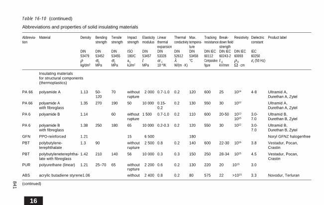
16
841
Table 16-10 (continued)
Abbreviations and properties of solid insulating materials
Abbrevia- Material Density Bending Tensile Impact Elasticity Linear Thermal Max. Tracking Break- Resistivity Dielectric Product labeltion strength strength strength modulus thermal conductivity tempera- resistance down field constant
expansion ture strengthDIN DIN DIN ISO DIN DIN DIN DIN DIN IEC DIN IEC DIN IEC IEC53479 53452 53455 180/C 53457 53328 52612 53458 60112 60243-2 60093 60250ρ σb σz an E α 1 λ °C Comparative Ed ρ D εr (50 Hz)kg/dm3 MPa MPa kJ/m2 MPa 10–4/K W/(m · K) figure kV/mm Ω · cm
Insulating materialsfor structural components(thermoplastics)
PA 66 polyamide A 1.13 50- 70 without 12 000 0.7-1.0 0.2 120 600 25 1014 4-8 Ultramid A,120 rupture Durethan A, Zytel
PA 66 polyamide A 1.35 270 190 50 10 000 0.15- 0.2 130 550 30 1012 Ultramid A,with fibreglass 0.2 Durethan A, Zytel
PA 6 polyamide B 1.14 60 without 1 500 0.7-1.0 0.2 110 600 20-50 1012- 3.0- Ultramid B,rupture 1015 7.0 Durethan B, Zytel
PA 6 polyamide B 1.38 250 180 65 10 000 0.2-0.3 0.2 120 550 30 1012 3.0- Ultramid B,with fibreglass 7.0 Durethan B, Zytel
GFN PPO-reinforced 1.21 15 16 500 180 Noryl GFNZ halogenfree
PBT polybutylene- 1.3 90 without 12 500 0.8 0.2 140 600 22-30 1016 3.8 Vestadur, Pocan,terephthalate rupture Crastin
PBT polybutyleneterephtha- 1.42 210 140 56 10 000 0.3 0.3 150 250 28-34 1015 4.5 Vestadur, Pocan,late with fibreglass Crastin
PUR polyurethane (linear) 1.21 25–70 65 without 12 200 0.6 0.2 130 220 20 1015 3.0rupture
ABS acrylic butadiene styrene1.06 without 12 400 0.8 0.2 80 575 22 >1015 3.3 Novodur, Terluran
(continued)
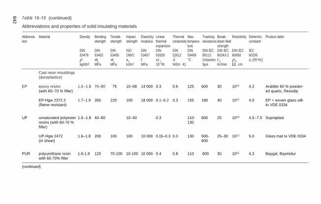
Table 16-10 (continued)
Abbreviations and properties of solid insulating materials
Abbrevia- Material Density Bending Tensile Impact Elasticity Linear Thermal Max. Tracking Break- Resistivity Dielectric Product labeltion strength strength strength modulus thermal conductivity tempera- resistance down field constant
expansion ture strengthDIN DIN DIN ISO DIN DIN DIN DIN DIN IEC DIN IEC DIN IEC IEC53479 53452 53455 180/C 53457 53328 52612 53458 60112 60243-2 60093 60250ρ σb σz an E α 1 λ °C Comparative Ed ρ D εr (50 Hz)kg/dm3 MPa MPa kJ/m2 MPa 10–4/K W/(m · K) figure kV/mm Ω · cm
Cast resin mouldings(duroplastics)
EP epoxy resins 1.6–1.8 70–80 175 10–68 14 000 0.3 0.6 125 600 30 1015 4.2 Araldite 60 % powder-(with 60–70 % filler) ed quartz, Resodip
EP-Hgw 2372.2 1.7–1.9 350 220 100 18 000 0.1–0.2 0.3 155 180 40 1012 4.0 EP + woven glass silk(flame resistant) to VDE 0334
UP unsaturated polyester 1.6–1.8 40–60 10–40 0.3 110- 600 25 1015 4.5–7.5 Supraplastresins (with 60-70 % 130filler)
UP-Hgw 2472 1.6–1.8 200 100 100 10 000 0.15–0.3 0.3 130 500- 25–30 1012 5.0 Glass mat to VDE 0334(in sheet) 600
PUR polyurethane resin 1.6-1.8 120 70-100 10-100 10 000 0.4 0.8 110 600 30 1015 4,3 Baygal, Baymidurwith 60-70% filler
(continued)
842

16
843
Table 16-10 (continued)
Abbreviations and properties of solid insulating materials
Abbrevia- Material Density Bending Tensile Impact Elasticity Linear Thermal Max. Tracking Break- Resistivity Dielectric Product labeltion strength strength strength modulus thermal conductivity tempera- resistance down field constant
expansion ture strengthDIN DIN DIN ISO DIN DIN DIN DIN DIN IEC DIN IEC DIN IEC IEC53479 53452 53455 180/C 53457 53328 52612 53458 60112 60243-2 60093 60250ρ σb σz an E α 1 λ °C Comparative Ed ρ Dkg/dm3 MPa MPa kJ/m2 MPa 10–4/K W/(m · K) figure kV/mm Ω · cm
Ceramic insulatingmaterials, e.g. post insulators,insulators, bushings
1) 2) 1) 2) 3)
KER 110.1 predominantly 2.4 160 140 130125 1.8 0.038 1.6 30–35 1011–1012 6 17/120 Porcelain, Hardaluminium porcelain, Melatith,
KER 110.2 silicate 2.5 100 180 160145 2.2 0.045 2.3 30–35 1011–1012 6 17/120 Karbowid 1203
KER 220 predominantly 2.6 120 120 160145 3 0.07 2.3 20 1012 6 2.5/65 Skalitmagnesium Frequenta, Calit,
KER 221 silicate 2.8 140 140 160145 4 0.06 2.3 30 1012 6 1.0/15 Dettan
KER 310 predominantly 3.5– 900– 300– 0.06– 10– 60KER 311 titanium 3.9 1500 800 0.08 20 40
oxide
KER 610 sintered corundum 3.4 – 120 183 40 0.07 16 25 7 AD 85 DegussitKER 611 Al2O3 3.9 – 90 0.08 36 AD 99.9 furnace
ceramic
zirconium 3.1 552 0.04 110 furnace ceramicceramic
1) Glazed 2) Unglazed 3) 20 °C / 100 °C
Note: The values given for mechanical properties may vary in practice, depending on how the materials are processed and the shape of the insulator.
ε r(5
0 Hz
)
ε rta
nδ· 1
03
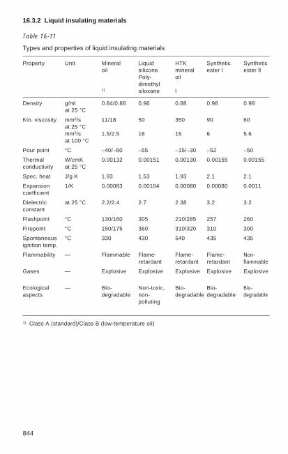
844
16.3.2 Liquid insulating materials
Table 16-11
Types and properties of liquid insulating materials
Property Unit Mineral Liquid HTK Synthetic Syntheticoil silicone mineral ester I ester ll
Poly- oildimethyl
1) siloxane l
Density g/ml 0.84/0.88 0.96 0.88 0.98 0.98at 25 °C
Kin. viscosity mm2/s 11/18 50 350 90 60at 25 °Cmm2/s 1.5/2.5 16 16 6 5.6at 100 °C
Pour point °C –40/–60 –55 –15/–30 –52 –50
Thermal W/cmK 0.00132 0.00151 0.00130 0.00155 0.00155conductivity at 25 °C
Spec. heat J/g K 1.93 1.53 1.93 2.1 2.1
Expansion 1/K 0.00083 0.00104 0.00080 0.00080 0.0011coefficient
Dielectric at 25 °C 2.2/2.4 2.7 2.38 3.2 3.2constant
Flashpoint °C 130/160 305 210/285 257 260
Firepoint °C 150/175 360 310/320 310 300
Spontaneous °C 330 430 540 435 435ignition temp.
Flammability — Flammable Flame- Flame- Flame- Non-retardant retardant retardant flammable
Gases — Explosive Explosive Explosive Explosive Explosive
Ecological — Bio- Non-toxic, Bio- Bio- Bio-aspects degradable non- degradable degradable degradable
polluting
1) Class A (standard)/Class B (low-temperature oil)

16
845
16.3.3 Gaseous insulating materials
Table 16-12
Properties of air and SF6
Gas Density1) Breakdown Dielectric constantfield strength
kg/m3 Ed kV/mm (50 Hz) εr (50 Hz)
Air (dry) 1.205 2.1 1.000576Sulphur hexafluoride 6.07 6 1.0021SF6
1) at 20 °C and 1013 mbar
Curves of pressure, temperature and density for SF6 gas are shown in Fig. 11-1. The insulating and arc-quenching properties of this gas are dealt with in Sections 10.4.4and 11.2.2.
16.4 Semi-finished products
16.4.1 Dimensions and weights of metal sheets, DIN EN 10130
Table 16-13
Weight per 1 m2 of sheet, in kg
Thickness Steel Aluminium Copper Brass Zinc Ribbed Profileds in mm sheet treadplate
0.5 3.925 1.34 4.45 4.275 3.6 – –0.75 5.888 2.01 6.657 6.413 5.4 – –1 7.85 2.68 8.9 8.55 7.2 – –1.5 11.775 4.02 13.35 12.825 10.8 – –2 15.7 5.36 17.8 17.10 14.4 – –2.5 19.63 6.7 22.25 21.38 18.0 – –3 23.6 8.04 26.7 26.65 21.6 30 254 31.4 10.72 35.6 34.20 28.8 38 345 39.3 13.4 44.5 42.75 36 46 426 47.2 16.08 53.4 51.3 43.2 54 518 64.0 21.6 71.6 68.4 57.6 70 67
Normal panel size 1000 mm × 2 000 mmSwitchboard sheet 1250 mm × 2 500 mmRibbed sheet and profiled treadplate 1250 mm × 2 500 mm

846
16.4.2 Slotted steel strip
Table 16-14
Slotted steel strip, hot-galvanized
Dimensions Slot size Weight Standard roll, in cut lengthslength 3 m approx.,
mm mm kg / m m m / bundle
20 × 1.5 40 × 5.5 0.187 200 6020 × 2 40 × 5.5 0.245 200 6025 × 2 40 × 5.5 0.326 200 6030 × 2.5 40 × 5.5 0.508 150 60
20 × 3 40 × 6.5 0.368 120 6025 × 3 40 × 6.5 0.489 120 6030 × 3 40 × 6.5 0.640 120 60
30 × 4 60 × 8.5 0.716 100 3040 × 4 70 × 8.5 1.038 180 3050 × 4 70 × 8.5 1.360 180 30
Steel earthing strip, hot-galvanized, DIN 48801
Dimensions Weight Standard rollmm kg / m m
20 × 2.5 0.400 10030 × 3.5 0.840 100 (50)30 × 4.0 0.961 13040 × 5.0 1.600 150
Accessories, plastic anchor plugs
Size Plug length Hole For screwsmm mm dia. mm dia. mm
15 25 15 2.5 – 1416 30 16 3.5 – 1516 60 16 3.5 – 1518 40 18 4.5 – 1618 75 18 4.5 – 1610 50 10 61. – 1812 60 12 81. – 10

16
847
16.4.3 Screws and accessories
Table 16-15
Standard screws and bolts (the figures denote DIN numbers)1)
1) as DlN-Normblatt-Verzeichnis. Published by Deutscher Normenausschuß (DNA). DIN and DIN ISO numbers shown abridged.
960
EN ISO 24 014 EN ISO 24 017
558
EN ISO 4762
EN ISO 10 642
EN ISO 7045 7988
603
975
EN ISO 27 436
EN ISO 1481

848
Table 16-16
Standard washers and nuts (the figures denote DIN numbers)1)
1) as DlN-Normblatt-Verzeichnis. Published by Deutscher Normenausschuß (DNA). DIN and DIN ISO numbers shown abridged.
EN ISO 1234
EN ISO 742, 10 513
EN ISO 10 511
555 934 970971 972 6915330386 64032ISO 4032EN 24032 ISO 4034
128128

16
849
16.4.4 Threads for bolts and screws
Table 16-17
Bolts and screws with metric thread, DIN 13 and DIN ISO 1502, dimensions in mm
Bolt Minor Lead Thick- Thick- Width Washer Drill holethreads thread ness of ness of across pass forNominal diameter head nut flats angles through threaddia- dia. dia.meterd dk h k m s e d1 s1
12 1.509 0.4 1.4 1.6 4 4.6 5 0.3 2.4 1.613 2.387 0.5 2 2.4 5.5 6.4 7 0.5 3.4 2.514 3.141 0.7 2.8 3.2 7 8.1 9 0.8 4.5 3.3
15 4.019 0.8 3.5 4.7 8 9.2 10 1.0 5.5 4.216 4.737 1 4.0 5.2 10 11.6 12.5 1.6 6.6 5.018 6.466 1.25 5.3 6.8 13 15 17 1.6 9 6.8
10 8.160 1.5 6.4 8.4 16 18.5 21 2.0 11 8.512 9.853 1.75 7.5 10.8 18 20.8 24 2.5 14 10.214 11.546 2 9 12.8 21 24.3 28 2.5 16 12
16 13.546 2 10 14.8 24 27.7 30 3 18 1418 14.933 2.5 11.5 15.8 27 31.2 34 4 20 15.520 16.933 2.5 12.5 18 30 34.7 37 3 22 17.5
22 18.933 2.5 14 19.4 34 38.3 39 3 24 19.524 20.319 3 15 21.5 36 41.6 44 4 26 2127 23.051 3 17 23.8 41 47.4 50 4 30 24
30 25.706 3.5 18.7 25.6 46 53.2 56 4 33 26.533 28.706 3.5 21 28.7 50 57.8 60 5 36 29.536 31.093 4 22.5 31 55 63.5 66 5 39 32
39 34.093 4 25 32 60 69.3 72 6 42 3542 36.479 4.5 26 34 65 75 78 7 45 37.5
Quality identification and mechanical properties of nuts and bolts: see technical terms of supply as perDIN 267, and also DIN ISO 8992, DIN EN 20898-2, DIN ISO 3269, DIN ISO 4042, DIN ISO 3506 andDIN EN ISO 2320.
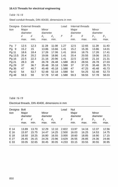
850
16.4.5 Threads for electrical engineering
Table 16-18
Steel conduit threads, DIN 40430, dimensions in mm
Designa- External threads Lead Internal threadstion Major Minor Major Minor
diameter diameter diameter diameterd d d1 d1 P D D D1 D1
max. min. max. min. min. max. min. max.
Pg 17 12.5 12.3 11 28 11.08 1.27 12.5 12.65 11.28 11.43Pg 19 15.2 15 13.86 13.66 1.41 15.2 15.35 13.86 14.01Pg 11 18.6 18.4 17.26 17.06 1.41 18.6 18.75 17.26 17.41Pg 13.5 20.4 20.2 19.06 18.86 1.41 20.4 20.55 19.06 19.21Pg 16 22.5 22.3 21.16 20.96 1.41 22.5 22.65 21.16 21.31Pg 21 28.3 28 26.78 26.48 1.588 28.3 28.55 26.78 27.03Pg 29 37 36.7 35.48 35.18 1.588 37 37.25 35.48 35.73Pg 36 47 46.7 45.48 45.18 1.588 47 47.25 45.48 45.73Pg 42 54 53.7 52.48 52.18 1.588 54 54.25 52.48 52.73Pg 48 59.3 59 57.78 57.48 1.588 59.3 59.55 57.78 58.03
Table 16-19
Electrical threads, DIN 40400, dimensions in mm
Designa- Bolt Lead Nuttion Major Minor Major Minor
diameter diameter diameter diameterd d d1 d1 P D D D1 D1
max. min. max. min. min. max. min. max.
E 14 13.89 13.70 12.29 12.10 2.822 13.97 14.16 12.37 12.56E 16 15.97 15.75 14.47 14.25 2.500 16.03 16.25 14.53 14.75E 18 18.50 18.25 16.80 16.55 3.000 18.60 18.85 16.90 17.15E 27 26.45 26.15 24.26 23.96 3.629 26.55 26.85 24.36 24.66E 33 33.05 32.65 30.45 30.05 4.233 33.15 33.55 30.55 30.95

17851
17 Miscellaneous
17.1 DIN VDE specifications and IEC publications for substationdesign
The VDE catalogue of (primarily technical safety) specifications for the entire field ofelectrical engineering in Germany is among the most important tasks of the VDEVerband der Elektrotechnik Elektronik Informationstechnik e.V. (VDE Association forElectrical Electronic & Information Technologies). The content, design, developmentand legal significance of the VDE catalogue of specifications are described in detail inVDE specification 0022 (latest edition: September 1994). Selected extracts of afundamental nature are quoted below:
“The stipulations contained in the VDE catalogue are drawn up by the DeutscheElektrotechnische Kommission (DKE) of DIN and VDE. The DKE is the German national organization for compiling national andinternational standards and VDE specifications in the entire field of electricalengineering in the Federal Republic.”“Results of international work are to be adopted as far as possible withoutalteration into the VDE standards catalogue and simultaneously into the DINcatalogue of standards.In the interests of European and worldwide harmonization, the rules of CENELEC(European Committee for Electrotechnical Standardization) impose an obligationto adopt certain standards of the International Electrotechnical Commission (IEC)and also European standards (EN) and harmonization documents (HD) issued byCENELEC.”
The component parts of the VDE standards catalogue are:– the rules and other rules relating thereto,– VDE specifications,– VDE guidelines,– attachments to rules, VDE specifications and VDE guidelines.
“The results of the DKE’s work on electrotechnical standardization, which includesafety regulations where appropriate, are registered as DIN standards, withadditional identification as VDE specification or VDE guideline, in the VDEstandards catalogue. The results of this work also include draft standards,amendments and the draft standards of the VDE:”
Standardization work for the field of electrical engineering is conducted almost entirelyon an international level. DKE is actively involved with the appointment of specialists tothe working groups, committees and other bodies of the international organizations andsubmits position papers on drafts and other queries and approves the acceptance ofregulations. The position papers are prepared by the relevant DKE committee.Agreements between IEC and CENELEC on one hand and between CENELEC andDKE on the other regulate the incorporation of international standards into nationalstandards. The national committee and the relevant DKE advisers section share theresponsibility for the publication schedule of the international standard translated intoGerman – without deviations or with only minor, clearly defined deviations – as aGerman standard.
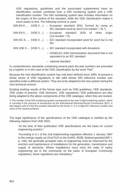
852
VDE regulations, guidelines and the associated supplements have anidentification number combined from a DIN numbering system and a VDEclassification number. The DIN numbering system also includes information onthe origins of the content of the standard, while the VDE classification makes itmuch easier to find. The following scheme is used:
DIN EN 6 .... (VDE 0 ...) – European standard (EN), formed by using an IEC standard word by word (1st number = 6) *)
DIN EN 5 .... (VDE 0 ...) – European standard (EN) of other origin (1st number = 5)
DIN IEC 6 .... (VDE 0 ...) – IEC standard incorporated word for word but is notEN
DIN VDE 0 .... (VDE 0 ...) – IEC standard incorporated with deviations
– CENELEC (HD) harmonization document that is notequivalent to an IEC standard
– national standard
In comprehensive standards comprising several parts the part numbers are precededby a hyphen or in the case of the VDE classification by the word “Part”.
Because the new identification system has only been defined since 1993, at present awhole series of VDE regulations is still valid whose DIN reference number wasspecified under a different system. They are to be adapted to the new system during thenext technical revision.
Existing working results of the former type such as VDE guidelines, VDE standards,VDE codes of practice, VDE directives, VDE regulations, VDE publications are alsobeing adapted to the above components of the VDE catalogue, when they are revised.
*) The number of the DIN numbering system corresponds to the new 5-digit numbering system, whichis currently in the process of introduction by the International Electrotechnical Commission (IEC). Italso begins with 6 in the first position followed by the former 2, 3 or 4-digit IEC reference number andzeros in the vacant positions.
The legal significance of the specifications of the VDE catalogue is clarified by thefollowing citations from VDE 0022.
“At the time of their publication VDE specifications are the basis for correctengineering practice.“
“According to § 1 of the 2nd implementing regulation effective 1 January 1987to the energy supply act (2nd DVO to the EnWG, BGBl. (federal gazette)1987 I,p. 146), the generally accepted rules of engineering must be observed for theerection and maintenance of installations for the generation, transmission andsupply of electricity. Where installations must meet the state of safetyengineering set in the community on the basis of European Communityregulations, these regulations are mandatory.”

17853
Group 1 Power installations
DIN 57100-100 (VDE 0100 Part 100) 1982-05Erection of power installations with rated voltages up to 1000 V– Scope; general requirements
DIN VDE 0100-200 (VDE 0100 Part 200) 1998-06Electrical installations of buildings – Terms and definitions
DIN VDE 0100-300 (VDE 0100 Part 300) 1996-01Erection of power installations with nominal voltages up to1000 V – Assessment of general characteristics of installations
IEC 60364-3, HD 384.3 S2
DIN VDE 0100-410 (VDE 0100 Part 410) 1997-01– Protection against electric shock IEC 60364-4-41,
HD 384.4.41 S2
DIN VDE 0100-420 (VDE 0100 Part 420) 1991-11– Protection against thermal effects
DIN VDE 0100-430 (VDE 0100 Part 430) 1991-11– Protection of cables and cords against overcurrent
DIN VDE 0100-442 (VDE 0100 Part 442) 1997-11Electrical installations of buildings– Protection of low-voltage installations against faults between
high-voltage systems and earth, HD 384.4.442 S1
further parts: 450, 460, 470, 482, 510, 520, 530, 537, 540, 550, 551, 559, 560, 610,620, 704, 705, 706, 707, 708 etc.
The VDE specifications must always be observed if one does not wish to be accused ofnot meeting the duty of care in the manufacture and maintenance of electricalinstallations and devices.
The following list shows an overview of the most important VDE specifications forswitchgear engineering. They are listed with their full numbering as at the end of 2000and the month in which they became effective. Because of the extent of the current DINVDE catalogue of specifications, this list cannot be considered complete. For example,later amendments, draft standards, supplements and drafts have generally not beenincluded. The majority of listed DIN VDE standards also have corresponding IEC or ENstandards. Where this is not the case, international standards are given if possible.
For improved clarity and to save space, some titles of standards are slightlyabbreviated. In standard series the general header has not been repeated in the list ofstandards immediately following.
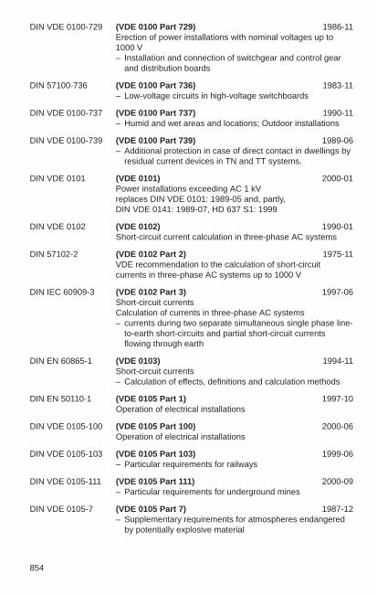
854
DIN VDE 0100-729 (VDE 0100 Part 729) 1986-11Erection of power installations with nominal voltages up to1000 V – Installation and connection of switchgear and control gear
and distribution boards
DIN 57100-736 (VDE 0100 Part 736) 1983-11– Low-voltage circuits in high-voltage switchboards
DIN VDE 0100-737 (VDE 0100 Part 737) 1990-11– Humid and wet areas and locations; Outdoor installations
DIN VDE 0100-739 (VDE 0100 Part 739) 1989-06– Additional protection in case of direct contact in dwellings by
residual current devices in TN and TT systems.
DIN VDE 0101 (VDE 0101) 2000-01Power installations exceeding AC 1 kVreplaces DIN VDE 0101: 1989-05 and, partly, DIN VDE 0141: 1989-07, HD 637 S1: 1999
DIN VDE 0102 (VDE 0102) 1990-01Short-circuit current calculation in three-phase AC systems
DIN 57102-2 (VDE 0102 Part 2) 1975-11VDE recommendation to the calculation of short-circuitcurrents in three-phase AC systems up to 1000 V
DIN IEC 60909-3 (VDE 0102 Part 3) 1997-06Short-circuit currents Calculation of currents in three-phase AC systems – currents during two separate simultaneous single phase line-
to-earth short-circuits and partial short-circuit currentsflowing through earth
DIN EN 60865-1 (VDE 0103) 1994-11Short-circuit currents – Calculation of effects, definitions and calculation methods
DIN EN 50110-1 (VDE 0105 Part 1) 1997-10Operation of electrical installations
DIN VDE 0105-100 (VDE 0105 Part 100) 2000-06Operation of electrical installations
DIN VDE 0105-103 (VDE 0105 Part 103) 1999-06– Particular requirements for railways
DIN VDE 0105-111 (VDE 0105 Part 111) 2000-09– Particular requirements for underground mines
DIN VDE 0105-7 (VDE 0105 Part 7) 1987-12– Supplementary requirements for atmospheres endangered
by potentially explosive material

17855
DIN VDE 0105-9 (VDE 0105 Part 9) 1986-05– Supplementary requirements for potentially explosive
atmospheres
DIN 57106-1 (VDE 0106 Part 1) 1982-05Protection against electric shock – Classification of electrical and electronic equipment
further parts: 100, 101, 102
DIN VDE 0107 (VDE 0107) 1994-10Electrical installations in hospitals and locations for medicaluse outside hospitals
DIN VDE 0108-1 (VDE 0108 Part 1) 1989-10Power installations and safety power supply in communalfacilities – General
further parts: 2, 3, 4, 5, 6, 7 and 8
E DIN VDE 0109-13 (VDE 0109 Part 13) 1990-09Insulation coordination in low-voltage systems – voltage testing of clearances, currently indraft
IEC 60664
further parts: 16, 19, 21, 22, 23, 24 (currently all in draft)
DIN VDE 0110-1 (VDE 0110 Part 1) 1997-04Insulation coordination for electrical equipment within low-voltage systems – Principles, requirements, tests
IEC 60664-1, HD 625.1 S1
further parts: 3, 20
DIN EN 60071-1 (VDE 0111 Part 1) 1996-07Insulation coordination – Definitions, principles and rules
DIN EN 60071-2 (VDE 0111 Part 2) 1997-09– Application guide
DIN EN 60204-1 (VDE 0113 Part 1) 1998-11Safety of machinery – Electrical equipment of machines – General requirements
numerous further parts
DIN EN 50163 (VDE 0115 Part 102) 1996-05Railway applications – Supply voltages of traction systems
DIN EN 50153 (VDE 0115 Part 2) 1996-12– Rolling stock– Protective provisions relating to electrical hazards
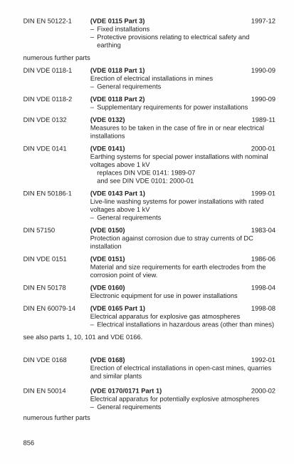
856
DIN EN 50122-1 (VDE 0115 Part 3) 1997-12– Fixed installations– Protective provisions relating to electrical safety and
earthing
numerous further parts
DIN VDE 0118-1 (VDE 0118 Part 1) 1990-09Erection of electrical installations in mines– General requirements
DIN VDE 0118-2 (VDE 0118 Part 2) 1990-09– Supplementary requirements for power installations
DIN VDE 0132 (VDE 0132) 1989-11Measures to be taken in the case of fire in or near electrical installations
DIN VDE 0141 (VDE 0141) 2000-01Earthing systems for special power installations with nominalvoltages above 1 kV
replaces DIN VDE 0141: 1989-07and see DIN VDE 0101: 2000-01
DIN EN 50186-1 (VDE 0143 Part 1) 1999-01Live-line washing systems for power installations with ratedvoltages above 1 kV – General requirements
DIN 57150 (VDE 0150) 1983-04Protection against corrosion due to stray currents of DCinstallation
DIN VDE 0151 (VDE 0151) 1986-06Material and size requirements for earth electrodes from thecorrosion point of view.
DIN EN 50178 (VDE 0160) 1998-04Electronic equipment for use in power installations
DIN EN 60079-14 (VDE 0165 Part 1) 1998-08Electrical apparatus for explosive gas atmospheres– Electrical installations in hazardous areas (other than mines)
see also parts 1, 10, 101 and VDE 0166.
DIN VDE 0168 (VDE 0168) 1992-01Erection of electrical installations in open-cast mines, quarriesand similar plants
DIN EN 50014 (VDE 0170/0171 Part 1) 2000-02Electrical apparatus for potentially explosive atmospheres – General requirements
numerous further parts
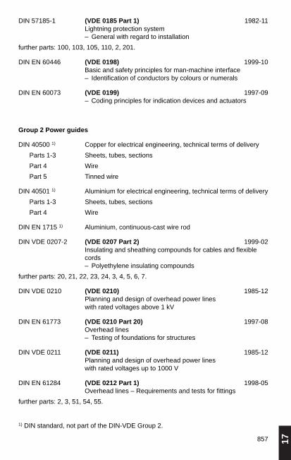
17857
DIN 57185-1 (VDE 0185 Part 1) 1982-11Lightning protection system – General with regard to installation
further parts: 100, 103, 105, 110, 2, 201.
DIN EN 60446 (VDE 0198) 1999-10Basic and safety principles for man-machine interface – Identification of conductors by colours or numerals
DIN EN 60073 (VDE 0199) 1997-09– Coding principles for indication devices and actuators
Group 2 Power guides
DIN 40500 1) Copper for electrical engineering, technical terms of delivery
Parts 1-3 Sheets, tubes, sections
Part 4 Wire
Part 5 Tinned wire
DIN 40501 1) Aluminium for electrical engineering, technical terms of delivery
Parts 1-3 Sheets, tubes, sections
Part 4 Wire
DIN EN 1715 1) Aluminium, continuous-cast wire rod
DIN VDE 0207-2 (VDE 0207 Part 2) 1999-02Insulating and sheathing compounds for cables and flexiblecords – Polyethylene insulating compounds
further parts: 20, 21, 22, 23, 24, 3, 4, 5, 6, 7.
DIN VDE 0210 (VDE 0210) 1985-12Planning and design of overhead power lines with rated voltages above 1 kV
DIN EN 61773 (VDE 0210 Part 20) 1997-08Overhead lines – Testing of foundations for structures
DIN VDE 0211 (VDE 0211) 1985-12Planning and design of overhead power lines with rated voltages up to 1000 V
DIN EN 61284 (VDE 0212 Part 1) 1998-05Overhead lines – Requirements and tests for fittings
further parts: 2, 3, 51, 54, 55.
1) DIN standard, not part of the DIN-VDE Group 2.

858
DIN VDE 0220-1 (VDE 0220 Part 1) 1971-11Specifications for detachable cable clamps to be used in power cable installations up to 1000 V
DIN VDE 0220-2 (VDE 0220 Part 2) 1971-11Specifications for pressed connectors to be used in powercable installations
DIN VDE 57220-3 (VDE 0220 Part 3) 1977-10Single and multiple cable clamps with insulating parts in powercable installations up to 1000 V
DIN VDE 0228-1 (VDE 0228 Part 1) 1987-12Proceedings in the case of interference on telecommunicationinstallations by electric power installations – General
DIN VDE 0228-2 (VDE 0228 Part 2) 1987-12– Interference by three-phase installations
further parts: 3, 4, 5, 6.
DIN 57250-1 (VDE 0250 Part 1) 1981-10Cables, wires and flexible cords for power installation – General
further parts: 102, 106, 201, 203, 204, 205, 206, 209, 210, 212, 213, 214, 407, 502,602, 603, 802, 806, 809, 811, 812, 813, 814, 815, 816
DIN VDE 0262 (VDE 0262) 1995-12XLPE insulated and PVC sheated installation cables withnominal voltages 0.6/1 kV
DIN VDE 0265 (VDE 0265) 1995-12Cables with plastic-insulated lead-sheath for power installation
DIN VDE 0266 (VDE 0266) 1997-11Power cables with improved characteristics in the case of fire;nominal voltages 0.6 /1 kV
DIN VDE 0271 (VDE 0271) 1997-06PVC-insulated cables and sheathed power cables for ratedvoltages up to and including 3.6/6 (7.2) kV
DIN VDE 0276-1000 (VDE 0276 Part 1000) 1995-06Power cables – Current-carrying capacity, general, conversion factors
DIN VDE 0276-603 (VDE 0276 Part 603) 2000-05– Distribution cables of nominal voltages 0.6/1 kV, HD 603 S1
DIN VDE 0276-604 (VDE 0276 Part 604) 1995-10– Power cables of nominal voltages 0.6/1 kV with special fire
performance for use in power stations, HD 604 S1

17859
DIN VDE 0276-620 (VDE 0276 Part 620) 1996-12– Power distribution cables with extruded insulation for
nominal voltages from 3.6 kV to 20.8/36 kV, HD 620 S1
DIN VDE 0276-621 (VDE 0276 Part 621) 1997-05– Power distribution cable with impregnated paper insulation
for medium voltage, HD 621 S1
DIN VDE 0276-622 (VDE 0276 Part 622) 1997-02– Power cable of rated voltages from 3.6/6 (7.2) kV up to
20.8/36 (42) kV with special fire performance for use inpower stations, HD 622/S1
DIN VDE 0276-626 (VDE 0276 Part 626) 1997-01– Overhead distribution cables of rated voltage 0.6/1 (1.2) kV,
HD 626 S1
DIN VDE 0276-632 (VDE 0276 Part 632) 1999-05Power cables with extruded insulation and their accessories – Rated voltages above 36 kV up to 150 kV, HD 632 S1
DIN VDE 0276-633 (VDE 0276 Part 633) 1999-05Tests on oil-filled, paper- or polypropylene paper laminate-insulated, metal-sheathed cables and accessories – Alternating voltages up to and including 400 kV, HD 633 S1
DIN VDE 0276-634 (VDE 0276 Part 634) 1999-05Tests on internal gas-pressure cables and accessories – Alternating voltages up to and including 275 kV, HD 634 S1
DIN VDE 0276-635 (VDE 0276 Part 635) 1999-05Tests on external gas-pressure cables and accessories – Alternating voltages up to and including 275 kV, HD 635 S1
DIN VDE 0278-623 (VDE 0278 Part 623) 1997-01Power cable accessories with rated voltages up to 30 kV (36 kV) –Specifications for joints, stop ends and outdoor terminations fordistribution cables of rated voltage 0.6/1 kV, HD 623 S1
DIN VDE 0278-628 (VDE 0278 Part 628) 1997-11– Test methods for accessories for power cables, with rated
voltages from 3.6/6 (7.2 kV) up to and including 20.8/36 (42)kV, HD 628 S1
DIN VDE 0278-629-1 (VDE 0278 Part 629-1) 1997-11– Test requirements on accessories for use on power cables of
rated voltage from 3.6/6 (7.2) kV up to 20.8/36 (42)kV– Cables with extruded solid insulation. HD 629.1 S1
DIN VDE 0278-629-2 (VDE 0278 Part 629-2) 1998-06– Cables with impregnated paper insulation, HD 629.2 S1
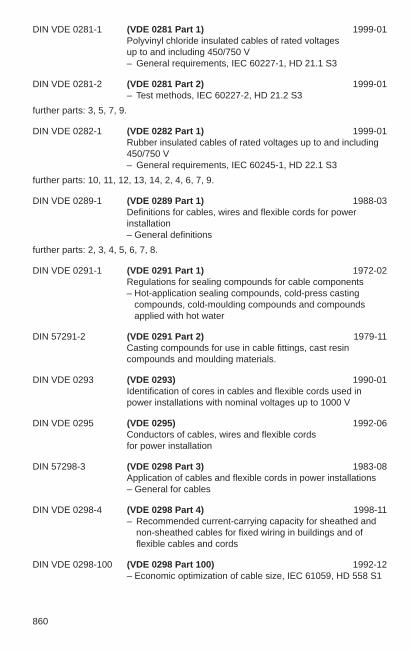
860
DIN VDE 0281-1 (VDE 0281 Part 1) 1999-01Polyvinyl chloride insulated cables of rated voltages up to and including 450/750 V – General requirements, IEC 60227-1, HD 21.1 S3
DIN VDE 0281-2 (VDE 0281 Part 2) 1999-01– Test methods, IEC 60227-2, HD 21.2 S3
further parts: 3, 5, 7, 9.
DIN VDE 0282-1 (VDE 0282 Part 1) 1999-01Rubber insulated cables of rated voltages up to and including450/750 V – General requirements, IEC 60245-1, HD 22.1 S3
further parts: 10, 11, 12, 13, 14, 2, 4, 6, 7, 9.
DIN VDE 0289-1 (VDE 0289 Part 1) 1988-03Definitions for cables, wires and flexible cords for powerinstallation – General definitions
further parts: 2, 3, 4, 5, 6, 7, 8.
DIN VDE 0291-1 (VDE 0291 Part 1) 1972-02Regulations for sealing compounds for cable components– Hot-application sealing compounds, cold-press casting
compounds, cold-moulding compounds and compoundsapplied with hot water
DIN 57291-2 (VDE 0291 Part 2) 1979-11Casting compounds for use in cable fittings, cast resincompounds and moulding materials.
DIN VDE 0293 (VDE 0293) 1990-01Identification of cores in cables and flexible cords used inpower installations with nominal voltages up to 1000 V
DIN VDE 0295 (VDE 0295) 1992-06Conductors of cables, wires and flexible cords for power installation
DIN 57298-3 (VDE 0298 Part 3) 1983-08Application of cables and flexible cords in power installations – General for cables
DIN VDE 0298-4 (VDE 0298 Part 4) 1998-11– Recommended current-carrying capacity for sheathed and
non-sheathed cables for fixed wiring in buildings and offlexible cables and cords
DIN VDE 0298-100 (VDE 0298 Part 100) 1992-12– Economic optimization of cable size, IEC 61059, HD 558 S1

17861
DIN VDE 0298-300 (VDE 0298 Part 300) 1999-04Guide to use of low-voltage harmonized cables, HD 516 S2
Group 3 Insulating materials
DIN VDE 0302-1 (VDE 0302 Part 1) 1986-09Insulation systems of electrical equipment – Evaluation and identification, IEC 60505
DIN VDE 0302-2 (VDE 0302 Part 2) 1986-09– Functional evaluation; aging mechanisms and diagnostic
procedures, IEC 60610
DIN VDE 0302-3 (VDE 0302 Part 3) 1986-09– Thermal endurance, fundamentals for test procedures,
IEC 60611
further parts: 4, 5, 6, 7, 8.
DIN IEC 60112 (VDE 0303 Part 1) 1984-06Method for determining the comparative and the proof-trackingindices of solid insulating materials under moist conditions
further parts: 4, 5, 6, 8, 10, 11, 12.
DIN EN 60243-1 (VDE 0303 Part 21) 1999-03Electric strength of insulation materials, test methods– Testing at power frequencies.
further parts: 22, 23, 30, 31, 32 etc.
DIN VDE 0304-1 (VDE 0304 Part 1) 1959-07Testing of solid insulation materials for assessment of theirthermal stability– Determination of thermal properties of solid insulating
materials
further parts: 3, 21, 22, 23, 23-3-2, 24.
DIN 57370-1 (VDE 0370 Part 1) 1978-12Insulating oils – New insulating oils for transformers and switchgear,
IEC 60296
DIN 57370-2 (VDE 0370 Part 2) 1978-12– Insulating oils in service in transformers and switchgear
DIN IEC 60475 (VDE 0370 Part 3) 1980-02– Method for sampling of liquid dielectrics
DIN EN 60156 (VDE 0370 Part 5) 1996-03– Determination of the breakdown voltage at power frequency,
test method

862
further parts: 6, 8, 9, 11, 12, 13, 14, 16, 20.
DIN IEC 60376 (VDE 0373 Part 1) 1980-04Requirements and acceptance of new sulfur hexafluoride (SF6)
DIN IEC 60480 (VDE 0373 Part 2) 1980-04Guideline to the checking of sulfur hexafluoride (SF6) takenfrom electrical equipment
Group 4 Measurement, control, testing
DIN EN 61010-1 (VDE 0411 Part 1) 1994-03Safety requirements for electrical equipment for measurement, control and laboratory use – General requirements
DIN EN 61557-1 (VDE 0413 Part 1) 1998-05Equipment for testing, measuring or monitoring of protective measures – General requirements
DIN EN 61557-2 (VDE 0413 Part 2) 1998-05– Insulation resistance
DIN EN 61557-3 (VDE 0413 Part 3) 1998-05– Loop impedance
DIN EN 61557-4 (VDE 0413 Part 4) 1998-05– Resistance of earth connections and equipotential bonding
DIN EN 61557-5 (VDE 0413 Part 5) 1998-05– Resistance to earth
DIN EN 61557-6 (VDE 0413 Part 6) 1999-05– Residual current devices (RCD) in TT, TN and IT systems
DIN EN 61557-7 (VDE 0413 Part 7) 1998-05– Phase sequence
DIN EN 61557-8 (VDE 0413 Part 8) 2000-04– Insulation monitoring devices for IT systems
DIN EN 60044-1 (VDE 0414 Part 1) 1994-01Instrument transformers – Current transformers
DIN VDE 0414-10 (VDE 0414 Part 10) 1985-05– Partial-discharge measurement, IEC 60044-4
DIN EN 60044-2 (VDE 0414 Part 2) 1999-12– Inductive voltage transformers

17863
DIN IEC 60044-3 (VDE 0414 Part 5) 1994-04– Combined transformers, HD 548.3 S1
DIN VDE 0414-6 (VDE 0414 Part 6) 1995-04– Three-phase voltage transformers
for voltage levels up to 52 kV, HD 587 S1
DIN EN 60044-6 (VDE 0414 Part 7) 1999-10– Requirements for protective current transformers
for transient performance
DIN EN 60521 (VDE 0418 Part 12) 1995-07Classes 0.5, 1 and 2 a.c. watt-hour meters
DIN VDE 0418-2 (VDE 0418 Part 2) 1966-03Electric integrating meters – Var-hour (reactive energy) meters
DIN EN 61268 (DE 0418 Part 20) 1996-11Alternating current static var-hour meters for reactive energy (classes 2 and 3)
DIN VDE 0418-3 (VDE 0418 Part 3) 1965-03Electric integrating meters – Direct-current meters
DIN VDE 0418-4 (VDE 0418 Part 4) 1967-07– Maximum demand indicators
DIN VDE 0418-5 (VDE 0418 Part 5) 1973-04– Telemetering devices
DIN EN 60514 (VDE 0418 Part 6) 1995-07Acceptance inspection of class 2 alternating current watt-hourmeters
DIN EN 61358 (VDE 0418 Part 60) 1996-11Acceptance inspection for direct-connected alternating current static watt-hour meters for active energy
DIN EN 61036 (VDE 0418 Part 7) 1997-05Alternating current electronic watt-hour meters for activeenergy (classes 1 and 2)
DIN EN 60687 (VDE 0418 Part 8) 1994-02Alternating current static watt-hour meters for active energy (classes 0.2 S and 0.5 S)
DIN EN 62053-31 (VDE 0418 Part 3-31) 1999-04Electricity metering equipment (AC) – Particular requirements – Pulse output devices for electromechanic and electronic
meters (only two-wire systems)

864
DIN EN 62053-61 (VDE 0418 Part 3-61) 1999-04– Power consumption and voltage requirements
DIN EN 61038 (VDE 0419 Part 1) 1994-03Time switches for tariff and load control
DIN EN 61037 (VDE 0420 Part 1) 1994-01Electronic ripple-control receivers for tariff and load control
DIN IEC 60060-1 (VDE 0432 Part 1) 1994-06High-voltage test techniques – General specifications and test requirements, HD 588.1 S1
DIN EN 61180-1 (VDE 0432 Part 10) 1995-05High-voltage test techniques for low-voltage equipment – Definitions, test and procedure requirements, EN 61180-1
DIN EN 61180-2 (VDE 0432 Part 11) 1995-05– Test equipment
DIN EN 60060-2 (VDE 0432 Part 2) 1996-03High-voltage test techniques – Measuring systems
DIN VDE 0432-5 (VDE 0432 Part 5) 1987-03– Oscilloscope and peak voltmeters for impulse test
DIN EN 61083-1 (VDE 0432 Part 7) 1994-04– Digital recorders for measurements in high-voltage impulse
tests– Requirements for digital recorders
DIN EN 61083-2 (VDE 0432 Part 8) 1998-01– Evaluation of software used for the determination
of the parameters of impulse waveforms
DIN 57434 (VDE 0434) 1983-05High-voltage test techniques– Measurement of partial discharges
Appendix 1 to DIN VDE 0435 (VDE 0435) 1999-01
Electrical relays – Synopsis, List of standards of the DIN VDE 0435 series
DIN VDE 0435-110 (VDE 0435 Part 110) 1989-04– Terms and definitions
DIN EN 61810-1 (VDE 0435 Part 201) 1999-04Electromechanical non-specified time all-or-nothing electrical relays – General requirements
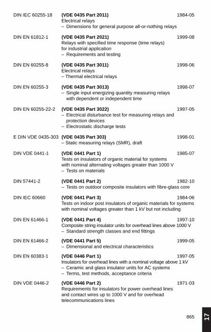
17865
DIN IEC 60255-18 (VDE 0435 Part 2011) 1984-05Electrical relays – Dimensions for general purpose all-or-nothing relays
DIN EN 61812-1 (VDE 0435 Part 2021) 1999-08Relays with specified time response (time relays) for industrial application – Requirements and testing
DIN EN 60255-8 (VDE 0435 Part 3011) 1998-06Electrical relays – Thermal electrical relays
DIN EN 60255-3 (VDE 0435 Part 3013) 1998-07– Single input energizing quantity measuring relays
with dependent or independent time
DIN EN 60255-22-2 (VDE 0435 Part 3022) 1997-05– Electrical disturbance test for measuring relays and
protection devices– Electrostatic discharge tests
E DIN VDE 0435-303 (VDE 0435 Part 303) 1998-01– Static measuring relays (SMR), draft
DIN VDE 0441-1 (VDE 0441 Part 1) 1985-07Tests on insulators of organic material for systems with nominal alternating voltages greater than 1000 V – Tests on materials
DIN 57441-2 (VDE 0441 Part 2) 1982-10– Tests on outdoor composite insulators with fibre-glass core
DIN IEC 60660 (VDE 0441 Part 3) 1984-06Tests on indoor post insulators of organic materials for systemswith nominal voltages greater than 1 kV but not including
DIN EN 61466-1 (VDE 0441 Part 4) 1997-10Composite string insulator units for overhead lines above 1000 V– Standard strength classes and end fittings
DIN EN 61466-2 (VDE 0441 Part 5) 1999-05– Dimensional and electrical characteristics
DIN EN 60383-1 (VDE 0446 Part 1) 1997-05Insulators for overhead lines with a nominal voltage above 1 kV– Ceramic and glass insulator units for AC systems– Terms, test methods, acceptance criteria
DIN VDE 0446-2 (VDE 0446 Part 2) 1971-03Requirements for insulators for power overhead lines and contact wires up to 1000 V and for overheadtelecommunications lines

866
DIN VDE 0446-3 (VDE 0446 Part 3) 1973-05– Requirements for accessories and fittings permanently
connected to the insulating body
DIN EN 60383-2 (VDE 0446 Part 4) 1995-08Insulators for overhead lines above 1000 V – Insulator strings and insulator sets for alternating voltage
systems– Terms and definitions, test methods, acceptance criteria
DIN EN 61325 (VDE 0446 Part 5) 1996-04– Ceramic or glass insulator units for DC systems– Terms and definitions, test methods, acceptance criteria
DIN EN 60305 (VDE 0446 Part 6) 1996-10– Ceramic and glass insulators for AC systems – Characteristics of insulator units of the cap-and-pin type
DIN EN 60433 (VDE 0446 Part 7) 1996-10– Ceramic insulators for AC systems – Characteristics of insulators in long-rod design
DIN EN 60507 (VDE 0448 Part 1) 1994-04Artificial pollution tests on high voltage insulators for AC systems
DIN EN 60529 (VDE 0470 Part 1) 2000-09Degrees of protection provided by enclosures (IP Code)
DIN EN 50102 (VDE 0470 Part 100) 1997-09Degrees of protection provided by enclosures for electricalequipment against external mechanical impacts (IK Code)
DIN EN 61032 (VDE 0470 Part 2) 1998-10Test probes for verification of protection of persons provided byenclosure
DIN EN 60695-1-1 (VDE 0471 Part 1-1) 2000-10Fire hazard testingGuidance for assessing the fire hazard of electrotechnicalproducts– General guidelines
numerous further parts
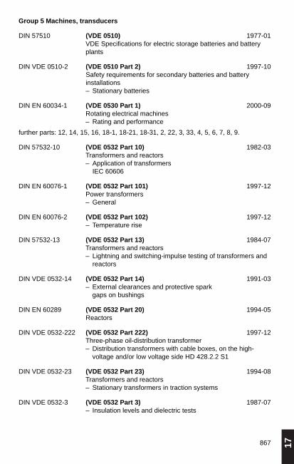
17867
Group 5 Machines, transducers
DIN 57510 (VDE 0510) 1977-01VDE Specifications for electric storage batteries and batteryplants
DIN VDE 0510-2 (VDE 0510 Part 2) 1997-10Safety requirements for secondary batteries and battery installations– Stationary batteries
DIN EN 60034-1 (VDE 0530 Part 1) 2000-09Rotating electrical machines – Rating and performance
further parts: 12, 14, 15, 16, 18-1, 18-21, 18-31, 2, 22, 3, 33, 4, 5, 6, 7, 8, 9.
DIN 57532-10 (VDE 0532 Part 10) 1982-03Transformers and reactors – Application of transformers
IEC 60606
DIN EN 60076-1 (VDE 0532 Part 101) 1997-12Power transformers – General
DIN EN 60076-2 (VDE 0532 Part 102) 1997-12– Temperature rise
DIN 57532-13 (VDE 0532 Part 13) 1984-07Transformers and reactors – Lightning and switching-impulse testing of transformers and
reactors
DIN VDE 0532-14 (VDE 0532 Part 14) 1991-03– External clearances and protective spark
gaps on bushings
DIN EN 60289 (VDE 0532 Part 20) 1994-05Reactors
DIN VDE 0532-222 (VDE 0532 Part 222) 1997-12Three-phase oil-distribution transformer – Distribution transformers with cable boxes, on the high-
voltage and/or low voltage side HD 428.2.2 S1
DIN VDE 0532-23 (VDE 0532 Part 23) 1994-08Transformers and reactors – Stationary transformers in traction systems
DIN VDE 0532-3 (VDE 0532 Part 3) 1987-07– Insulation levels and dielectric tests

868
DIN EN 60214 (VDE 0532 Part 30) 1998-06On-load tap-changers
DIN VDE 0532-31 (VDE 0532 Part 31) 1993-04Transformers and reactors – Selection and application of on-load tap-changers
DIN 57532-5 (VDE 0532 Part 5) 1984-05– Ability to withstand short-circuit
DIN VDE 0532-6 (VDE 0532 Part 6) 1994-01– Dry-type power transformers
DIN EN 60551 (VDE 0532 Part 7) 1993-11Determination of transformer and reactor sound levels
DIN VDE 0558-1 (VDE 0558 Part 1) 1987-07Semiconductor converters – General specifications and particular specifications
for line-commutated convertors, IEC 60119
DIN EN 60146-1-1 (VDE 0558 Part 11) 1994-03– General requirements and line-commutated converters – Specification of the basic requirements
DIN 57558-2 (VDE 0558 Part 2) 1977-08– Particular requirements for self-commutated converters
DIN 57558-3 (VDE 0558 Part 3) 1977-08– Particular requirements for DC convertors (DC chopper
convertors)
DIN 57558-5 (VDE 0558 Part 5) 1988-09– Uninterruptible power systems (UPS), IEC 60146-4
DIN EN 50091-1-1 (VDE 0558 Part 511) 1997-07Uninterruptible power systems (UPS)– General requirements and safety requirements for UPS used
in operator access areas
DIN EN 50091-1-2 (VDE 0558 Part 512) 1999-05– General requirements and safety requirements for UPS used
in restricted access locations
DIN EN 50091-2 (VDE 0558 Part 520) 1996-05– EMC requirements
DIN VDE 0558-6 VDE 0558 Part 6) 1992-04– Switches for UPS, IEC 60146-5
DIN EN 60146-1-3 (VDE 0558 Part 8) 1994-03– General requirements and line-commutated converter– Transformers and reactors
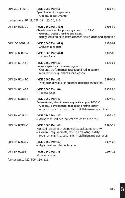
17869
DIN VDE 0560-1 (VDE 0560 Part 1) 1969-12Specification for capacitors – General requirements
further parts: 10, 11, 120, 121, 15, 16, 2, 3.
DIN EN 60871-1 (VDE 0560 Part 410) 1998-09Shunt capacitors for power systems over 1 kV– General, design, testing and rating,
safety requirements, instructions for installation and operation
DIN IEC 60871-2 (VDE 0560 Part 420) 1993-04– Endurance testing
DIN EN 60871-4 (VDE 0560 Part 440) 1997-08– Internal fuses
DIN EN 60143-1 (VDE 0560 Part 42) 1995-01Series capacitors for power systems– General, performance, testing and rating, safety
requirements, guidelines for erection
DIN EN 60143-2 (VDE 0560 Part 43) 1995-12– Protection devices for batteries of series capacitors
DIN EN 60143-3 (VDE 0560 Part 44) 1999-03– Internal fuses
DIN EN 60381-1 (VDE 0560 Part 46) 1997-12Self-restoring shunt power capacitors up to 1000 V – General, performance, testing and rating, safety
requirements, instructions for installation and operation
DIN EN 60381-2 (VDE 0560 Part 47) 1997-09– Aging test, self-healing test and destruction test
DIN EN 60931-1 (VDE 0560 Part 48) 1997-12Non-self-restoring shunt power capacitors up to 1 kV – General, requirements, testing and rating, safety
requirements, instructions for installation and operation
DIN EN 60931-2 (VDE 0560 Part 49) 1997-08– Aging test and destruction test
DIN EN 60252 (VDE 0560 Part 8) 1994-11Motor capacitors
further parts: 430, 800, 810, 811.

870
Group 6 Installation material, switchgear
DIN VDE 0603-1 (VDE 0603 Part 1) 1991-10Consumer units and meter panels AC 400 V – Consumer units and meter panels
DIN VDE 0603-2 (VDE 0603 Part 2) 1998-03– Main line branch terminals
DIN EN 50085-1 (VDE 0604 Part 1) 1998-04Cable trunking systems and cable ducting systems for electrical installations – General requirements
DIN VDE 0604-2 (VDE 0604 Part 2) 1986-05– Trunking for appliances
DIN VDE 0604-3 (VDE 0604 Part 3) 1986-05– Skirting board ducts
DIN EN 50086-1 (VDE 0605 Part 1) 1994-05Conduit systems for electrical installations – General requirements
DIN EN 50086-2-1 (VDE 0605 Part 2-1) 1995-12– Rigid conduit systems
DIN EN 50086-2-2 (VDE 0605 Part 2-2) 1995-12– Pliable conduit systems
DIN EN 50086-2-3 (VDE 0605 Part 2-3) 1995-12– Flexible conduit systems
DIN EN 50086-2-4 (VDE 0605 Part 2-4) 1994-09– Underground buried conduit systems
DIN VDE 0606-1 (VDE 0606 Part 1) 2000-10Connecting materials up to 690 V – Installation boxes for accomodation of equipment and/or
connecting terminals
DIN EN 60999-1 (VDE 0609 Part 1) 2000-12Connecting devices - Electrical copper conductors– Safety requirements for screw-type and screwless-type
clamping units
DIN EN 60947-7-1 (VDE 0611 Part 1) 2000-05Low-voltage switchgear and controlgear– Anciliary equipment Section 1:
Terminal blocks for copper conductors
further parts: 20, 3, 4

17871
DIN VDE 0618-1 (VDE 0618 Part 1) 1989-08Equipment for equipotential bonding
DIN EN 50262 (VDE 0619) 1999-04Metric cable glands for electrical installations
DIN VDE 0620 (VDE 0620) 1992-05Plugs and socket-outlets up to 400 V, 25 A
further parts: 101, 300.
DIN EN 60309-1 (VDE 0623 Part 1) 2000-05Plugs and socket-outlets and couplers for industrial purposes, general requirements
further parts: 20, 4, 100.
DIN EN 61058-1 (VDE 0630 Part 1) 1993-05Switches for appliances – General requirements
DIN VDE 0630-12 (VDE 0630 Part 12) 1988-09Switches for appliances for a rated voltage not exceeding 500 V and a rated current not exceeding 63 A, – Electronic switches
DIN EN 60669-1 (VDE 0632 Part 1) 1996-04Switches for household and similar fixed electrical installations – General requirements
and further parts.
DIN VDE 0633-1 (VDE 0633 Part 1) 1989-01Time switches – General requirements
DIN VDE 0633-2 (VDE 0633 Part 2) 1986-02– Electronic time switches
DIN VDE 0634-1 (VDE 0634 Part 1) 1987-09Underfloor electrical installation – Service units
and Part 2.
DIN 57635 (VDE 0635) 1984-02Low-voltage fuses – D-fuses 16 up to 25 A, 500 V, – D-fuses up to 100 A, 750 V, – D-fuses up to 100 A, 500 V.
DIN EN 60269-1 (VDE 0636 Part 10) 1999-11– General requirements
DIN EN 60269-2 (VDE 0636 Part 20) 1995-12– Fuses for use by authorized persons

872
DIN EN 60269-3 (VDE 0636 Part 30) 1995-12– Fuses for use by unskilled persons
DIN EN 60269-4 (VDE 0636 Part 40) 1997-04– Fuse links for protection of semiconductor elements
DIN VDE 0636-201 (VDE 0636 Part 201) 1998-06 Low-voltage fuses (HRC)– Fuses for use by authorized persons, IEC 60269-2-1,
HD 630.2.1 S2
DIN VDE 0636-2011 (VDE 0636 Part 2011) 1999-05– National supplement to VDE 0636 Part 201:
protection of special electrical systems
DIN VDE 0636-301 (VDE 0636 Part 301) 1998-01Low-voltage fuses (D type), – Fuses for use by unskilled persons, IEC 60269-3-1,
HD 630.3.1 S2
DIN VDE 0636-3011 (VDE 0636 Part 3011) 1999-05– National supplement to VDE 0636 Part 301
DIN 57638 (VDE 0638) 1981-09Low-voltage switchgear – Fuse-switch units, DO system
DIN VDE 0641-11 (VDE 0641 Part 11) 1992-08Circuit-breakers for overcurrent protection for domestic useIEC 60898, EN 60898
DIN 57641-2 (VDE 0641 Part 2) 1984-04Miniature circuit-breakers up to 63 A and up to 440 V directvoltage
DIN 57641-3 (VDE 0641 Part 3) 1984-04Miniature circuit-breakers up to 63 A and up to 415 Valternating voltage and up to 440 V direct voltage
DIN EN 60934 (VDE 0642) 1995-04Circuit breakers for equipment (CBE)
DIN EN 60947-1 (VDE 0660 Part 100) 1999-12Low-voltage switchgear and control gear – General rules
DIN EN 60947-2 (VDE 0660 Part 101) 1997-02– Circuit breakers
DIN VDE 0660-102 (VDE 0660 Part 102) 1992-07– Electromechanical contactors and motor-starters
IEC 60947-4-1, EN 60947-4-1

17873
DIN 57660-103 (VDE 0660 Part 103) 1984-03Switchgear – High-voltage alternating current contactors
above 1000 V up to 12000 V
DIN 57660-105 (VDE 0660 Part 105) 1984-03– High-voltage motor starters,
Direct-on-Line (full voltage) AC starters
DIN EN 60941-3 (VDE 0660 Part 107) 2000-02Low-voltage switchgear and control gear – Switches, disconnectors, switch disconnectors
and fuse-combination units
DIN VDE 0660-109 (VDE 0660 Part 109) 2000-09– AC semiconductor controllers and contactors for non-motor
loads, IEC60158-2
DIN VDE 0660-112 (VDE 0660 Part 112) 1987-02– Direct current air-break switches, air-break disconnectors
and air-break switch-disconnectors over 1200 V up to 3000 V
DIN VDE 0660-114 (VDE 0660 Part 114) 1992-07– Automatic transfer switching equipment
IEC 60947-6-1, EN 60947-6-1
DIN EN 60947-6-2 (VDE 0660 Part 115) 1993-09– Control and protective switching devices (CPS)
DIN EN 60947-4-2 (VDE 0660 Part 117) 2000-09– AC semiconductor-motor controllers and starters
DIN EN 60947-5-1 (VDE 0660 Part 200) 2000-08– Electromechanical control circuit devices
DIN EN 60947-5-2 (VDE 0660 Part 208) 2000-08– Proximity switches
DIN VDE 0660-209 (VDE 0660 Part 209) 1988-01– Proximity position switches for safety functions
DIN EN 60947-5-5 (VDE 0660 Part 210) 1998-01– Control circuit devices and switching elements – Electrical emergency stop devices with mechanical latching
function
DIN VDE 0660-302 (VDE 0660 Part 302) 1987-02Thermal rotating machines protection – Thermal detectors and control units
DIN VDE 0660-303 (VDE 0660 Part 303) 1987-02– PTC thermal detectors and control units
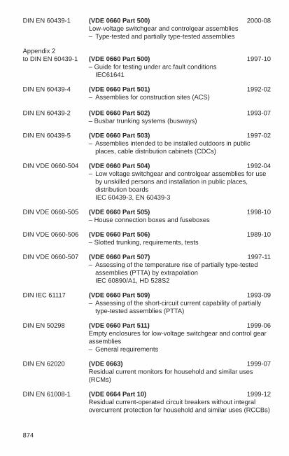
874
DIN EN 60439-1 (VDE 0660 Part 500) 2000-08Low-voltage switchgear and controlgear assemblies – Type-tested and partially type-tested assemblies
Appendix 2 to DIN EN 60439-1 (VDE 0660 Part 500) 1997-10
– Guide for testing under arc fault conditionsIEC61641
DIN EN 60439-4 (VDE 0660 Part 501) 1992-02– Assemblies for construction sites (ACS)
DIN EN 60439-2 (VDE 0660 Part 502) 1993-07– Busbar trunking systems (busways)
DIN EN 60439-5 (VDE 0660 Part 503) 1997-02– Assemblies intended to be installed outdoors in public
places, cable distribution cabinets (CDCs)
DIN VDE 0660-504 (VDE 0660 Part 504) 1992-04– Low voltage switchgear and controlgear assemblies for use
by unskilled persons and installation in public places,distribution boardsIEC 60439-3, EN 60439-3
DIN VDE 0660-505 (VDE 0660 Part 505) 1998-10– House connection boxes and fuseboxes
DIN VDE 0660-506 (VDE 0660 Part 506) 1989-10– Slotted trunking, requirements, tests
DIN VDE 0660-507 (VDE 0660 Part 507) 1997-11– Assessing of the temperature rise of partially type-tested
assemblies (PTTA) by extrapolationIEC 60890/A1, HD 528S2
DIN IEC 61117 (VDE 0660 Part 509) 1993-09– Assessing of the short-circuit current capability of partially
type-tested assemblies (PTTA)
DIN EN 50298 (VDE 0660 Part 511) 1999-06Empty enclosures for low-voltage switchgear and control gearassemblies – General requirements
DIN EN 62020 (VDE 0663) 1999-07Residual current monitors for household and similar uses(RCMs)
DIN EN 61008-1 (VDE 0664 Part 10) 1999-12Residual current-operated circuit breakers without integralovercurrent protection for household and similar uses (RCCBs)
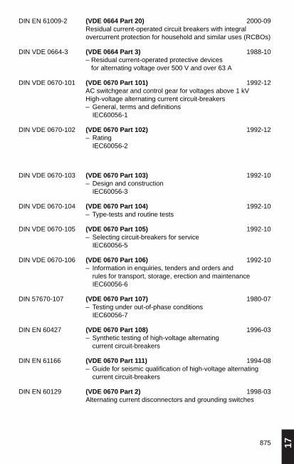
17875
DIN EN 61009-2 (VDE 0664 Part 20) 2000-09Residual current-operated circuit breakers with integral overcurrent protection for household and similar uses (RCBOs)
DIN VDE 0664-3 (VDE 0664 Part 3) 1988-10– Residual current-operated protective devices
for alternating voltage over 500 V and over 63 A
DIN VDE 0670-101 (VDE 0670 Part 101) 1992-12AC switchgear and control gear for voltages above 1 kV High-voltage alternating current circuit-breakers– General, terms and definitions
IEC60056-1
DIN VDE 0670-102 (VDE 0670 Part 102) 1992-12– Rating
IEC60056-2
DIN VDE 0670-103 (VDE 0670 Part 103) 1992-10– Design and construction
IEC60056-3
DIN VDE 0670-104 (VDE 0670 Part 104) 1992-10– Type-tests and routine tests
DIN VDE 0670-105 (VDE 0670 Part 105) 1992-10– Selecting circuit-breakers for service
IEC60056-5
DIN VDE 0670-106 (VDE 0670 Part 106) 1992-10– Information in enquiries, tenders and orders and
rules for transport, storage, erection and maintenanceIEC60056-6
DIN 57670-107 (VDE 0670 Part 107) 1980-07– Testing under out-of-phase conditions
IEC60056-7
DIN EN 60427 (VDE 0670 Part 108) 1996-03– Synthetic testing of high-voltage alternating
current circuit-breakers
DIN EN 61166 (VDE 0670 Part 111) 1994-08– Guide for seismic qualification of high-voltage alternating
current circuit-breakers
DIN EN 60129 (VDE 0670 Part 2) 1998-03Alternating current disconnectors and grounding switches

876
DIN EN 61129 (VDE 0670 Part 212) 1995-02– Alternating current grounding switches, induced current
switching
DIN EN 61259 (VDE 0670 Part 213) 1996-06Gas-insulated metal-enclosed switchgear for rated voltages of72.5 kV and above – Requirements for switching bus charging currents by
disconnectors
DIN EN 60265-1 (VDE 0670 Part 301) 1999-05 High-voltage. switches
– High-voltage switches over 1 kV and below 52 kV
DIN EN 60265-2 (VDE 0670 Part 302) 1998-09– High-voltage switches for rated voltages of 52 kV
and above
DIN EN 60420 (VDE 0670 Part 303) 1994-09– High-voltage alternating current switch-fuse
combinations
DIN EN 60282-1 (VDE 0670 Part 4) 1998-02High-voltage fuses – Current-limiting fuses
DIN EN 60644 (VDE 0670 Part 401) 1997-03– High voltage fuse – links for motor circuit applications
DIN VDE 0670-402 (VDE 0670 Part 402) 1988-05 – Selection of fuse-links for transformer circuits
DIN EN 60298 (VDE 0670 Part 6) 1998-05AC metal-enclosed switchgear and control gear for rated voltages above 1 kV and up to and including 52 kV
DIN EN 61330 (VDE 0670 Part 611) 1997-08High-voltage/low-voltage prefabricated substations
DIN EN 60517 (VDE 0670 Part 8) 1998-10Gas-insulated metal-enclosed high-voltage switchgear andcontrolgear for rated voltages of 72.5 kV and above
DIN VDE 0670-801 (VDE 0670 Part 801) 1987-04Alternating-current switchgear for voltages above 1 kV – Cast aluminium alloy enclosures for gas-filled high-voltage
switchgear and controlgear
EN 50052
DIN VDE 0670-803 (VDE 0670 Part 803) 1991-05– Wrought-aluminium and aluminium alloy enclosures for gas-
filled high-voltage switchgear and controlgearEN 50064
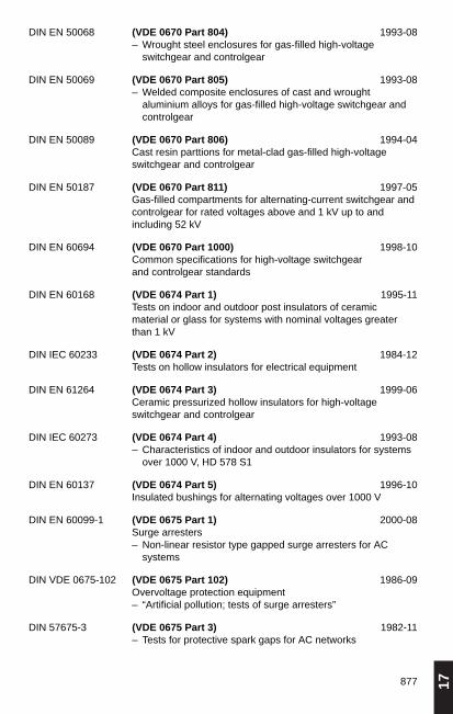
17877
DIN EN 50068 (VDE 0670 Part 804) 1993-08– Wrought steel enclosures for gas-filled high-voltage
switchgear and controlgear
DIN EN 50069 (VDE 0670 Part 805) 1993-08– Welded composite enclosures of cast and wrought
aluminium alloys for gas-filled high-voltage switchgear andcontrolgear
DIN EN 50089 (VDE 0670 Part 806) 1994-04Cast resin parttions for metal-clad gas-filled high-voltageswitchgear and controlgear
DIN EN 50187 (VDE 0670 Part 811) 1997-05Gas-filled compartments for alternating-current switchgear andcontrolgear for rated voltages above and 1 kV up to andincluding 52 kV
DIN EN 60694 (VDE 0670 Part 1000) 1998-10Common specifications for high-voltage switchgear and controlgear standards
DIN EN 60168 (VDE 0674 Part 1) 1995-11Tests on indoor and outdoor post insulators of ceramic material or glass for systems with nominal voltages greaterthan 1 kV
DIN IEC 60233 (VDE 0674 Part 2) 1984-12Tests on hollow insulators for electrical equipment
DIN EN 61264 (VDE 0674 Part 3) 1999-06Ceramic pressurized hollow insulators for high-voltageswitchgear and controlgear
DIN IEC 60273 (VDE 0674 Part 4) 1993-08– Characteristics of indoor and outdoor insulators for systems
over 1000 V, HD 578 S1
DIN EN 60137 (VDE 0674 Part 5) 1996-10Insulated bushings for alternating voltages over 1000 V
DIN EN 60099-1 (VDE 0675 Part 1) 2000-08Surge arresters – Non-linear resistor type gapped surge arresters for AC
systems
DIN VDE 0675-102 (VDE 0675 Part 102) 1986-09Overvoltage protection equipment – “Artificial pollution; tests of surge arresters”
DIN 57675-3 (VDE 0675 Part 3) 1982-11– Tests for protective spark gaps for AC networks

878
DIN EN 60099-4 (VDE 0675 Part 4) 1994-05– Metal oxide surge arresters without gaps for AC systems
DIN EN 60099-5 (VDE 0675 Part 5) 1997-08Surge arresters, selection and application recommendations
DIN 57680-1 (VDE 0680 Part 1) 1983-01Personal protective equipment, protective devices andapparatus for work on electrically energized systems up to1000 V– Personal protective equipment and protective insulating
devices
DIN 57680-3 (VDE 0680 Part 3) 1977-09– Operating rods and current-collecting devices
DIN 57680-4 (VDE 0680 Part 4) 1980-11– Fuse handles for low-voltage HRC fuses
DIN 57680-6 (VDE 0680 Part 6) 1977-04– Single-pole voltage testers up to 250 V AC
DIN 57680-7 (VDE 0680 Part 7) 1984-02– Socket spanner
DIN VDE 0681-1 (VDE 0681 Part 1) 1986-10Operating, testing and safeguarding devices for work onelectrically energized systems with rated voltages exceeding 1 kV– General requirements
DIN 57681-2 (VDE 0681 Part 2) 1977-03– Operating rods
DIN 57681-3 (VDE 0681 Part 3) 1977-03– Fuse tongs
DIN VDE 0681-5 (VDE 0681 Part 5) 1985-06– Phase comparators
DIN VDE 0681-6 (VDE 0681 Part 6) 1985-06– Voltage detectors for overhead contact systems on electrical
railways 15 kV, 16 2/3 Hz
DIN VDE 0681-8 (VDE 0681 Part 8) 1988-05– Insulating protective shutters
DIN EN 60900 (VDE 0682 Part 201) 1994-08Hand-tools for live working up to AC 1000 V and DC 1500 V
DIN EN 60832 (VDE 0682 Part 211) 1998-01Insulating poles and universal tool attachments (fittings) for liveworking

17879
DIN EN 60903 (VDE 0682 Part 311) 1994-10– Specification for gloves and mitts of insulating material for
live working
DIN EN 60984 (VDE 0682 Part 312) 1994-10– Sleeves of insulating material for live working
DIN EN 61243-3 (VDE 0682 Part 401) 1999-09– Two-pole low-voltage voltage detectors
DIN EN 61243-1 (VDE 0682 Part 411) 1998-05Live working – Voltage detectors,
capacitive type for alternating voltage over 1 kV
DIN EN 61229 (VDE 0682 Part 551) 1997-01Rigid protective covers for live working on AC installations
DIN EN 61236 (VDE 0682 Part 651) 1996-11Saddles, pole clamps (stick clamps) and accessories for liveworking
DIN EN 61057 (VDE 0682 Part 741) 1995-08Aerial devices with insulating boom for live workingover AC 1 kV
DIN EN 61230 (VDE 0683 Part 100) 1996-11Live working – Portable equipment for earthing or earthing
and short-circuiting
DIN EN 61219 (VDE 0683 Part 200) 1995-01– Earthing or earthing and short-circuiting equipment using
lancesas short-circuiting device
Group 8 Information technology
DIN VDE 0800-1 (VDE 0800 Part 1) 1989-05Telecommunications – Requirements and tests for the safety of facilities and
apparatus
DIN VDE 0800-2 (VDE 0800 Part 2) 1985-07– Earthing and equipotential bonding
DIN VDE 0800-3 (VDE 0800 Part 3) 1983-06– Telecommunication facilities with remote supply
DIN VDE 0800-4 (VDE 0800 Part 4) 1986-03– Erection of telecommunications lines
DIN VDE 0800-5 (VDE 0800 Part 5) 1991-01– Power supply

880
DIN V VDE 0801 (VDE 0801) Draft standard 1990-01– Principles for computers in safety-related systems
DIN EN 41003 (VDE 0804 Part 100) 1999-08Particular safety requirements for equipment to be connectedto telecommunication networks
DIN EN 60950 (VDE 0805) 1997-11Safety of information technology equipment
DIN EN 50116 (VDE 0805 Part 116) 1997-06Information-technology equipment – Testing (100 %) for production
DIN EN 50065-1 (VDE 0808 Part 1) 1996-11Signaling on low-voltage electrical installations in the frequencyrange 3 kHz to 148.5 kHz.
DIN VDE 0812 (VDE 0812) 1988-11Telecommunications and data-processing systems – Equipment wires and stranded equipment wires
with PVC insulation sheaths
DIN VDE 0813 (VDE 0813) 1988-11 s– Switchboard cables
DIN VDE 0814 (VDE 0814) 1981-10– Cords
DIN VDE 0815 (VDE 0815) 1985-09– Wiring cables and wires
DIN VDE 0816-1 (VDE 0816 Part 1) 1988-02– External cables with insulation and sheaths of polyethylene
DIN VDE 0816-2 (VDE 0816 Part 2) 1988-02– External cables, signal and measuring cables, mine cables
DIN VDE 0816-3 (VDE 0816 Part 3) 1988-02– External cables with paper insulation
DIN VDE 0817 (VDE 0817) 1990-08– Lines with stranded conductors for increased mechanical
stress
DIN 57818 (VDE 0818) 1983-02Self supporting telecommunication aerial cables on overhead power lines above 1 kV
DIN VDE 0819-1 (VDE 0819 Part 1) 1994-04Multicore and symmetric pair / quad and multicore cables fordigital data transmission, HD 608 S1

17881
DIN VDE 0819-100 (VDE 0819 Part 100) 1998-05Materials used in communication cables – General, HD 624.0 S1
DIN VDE 0819-101 (VDE 0819 Part 101) 1995-02– PVC insulating compounds, HD 624.1 S1
DIN VDE 0819-102 (VDE 0819 Part 102) 1995-02– PVC sheathing compounds, HD 624.2 S1
DIN VDE 0819-103 (VDE 0819 Part 103) 1995-02– Polyethylene insulating compounds, HD 624.3 S1
DIN VDE 0819-104 (VDE 0819 Part 104) 1997-07– Polyethylene sheathing compounds, HD 624.4 S1
DIN VDE 0819-105 (VDE 0819 Part 105) 1996-02– Polypropylene insulation compounds, HD 624.5 S1
DIN VDE 0819-106 (VDE 0819 Part 106) 1996-02– Halogen-free, fire-retardant insulation compounds,
HD 624.6 S1
DIN VDE 0819-107 (VDE 0819 Part 107) 1995-02– Halogen-free, fire-retardant thermoplastic sheating
compounds, HD 624.7 S1
DIN VDE 0819-108 (VDE 0819 Part 108) 1996-02– Filling compounds for filled cables, HD 624.8 S1
DIN VDE 0819-109 (VDE 0819 Part 109) 1997-07– Cross-linked PE insulation, HD 624.9 S1
DIN EN 50167 (VDE 0819 Part 2) 1995-08Sectional specification for cables for digital communications – Floor wiring cables with common overall screen
DIN EN 50168 (VDE 0819 Part 3) 1995-08– Work area wiring cables with common overall screen
DIN EN 50169 (VDE 0819 Part 4) 1995-08– Backbone cables, riser and campus with common overall
screen
DIN VDE 0819-5 (VDE 0819 Part 5) 1997-11– Equipment cables for digital and analog communications,
HD 609 S1
DIN VDE 0820-1 (VDE 0820 Part 1) 1992-11Miniature fuses – Terms and definitions, requirements
for cartridge fuse links IEC 60127-1, EN 60127-1
DIN EN 60127-2 (VDE 0820 Part 2) 1996-08– Cartridge fuse links
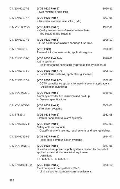
882
DIN EN 60127-3 (VDE 0820 Part 3) 1996-11– Sub-miniature fuse links
DIN EN 60127-4 (VDE 0820 Part 4) 1997-05– Universal modular fuse links (UMF)
DIN VDE 0820-5 (VDE 0820 Part 5) 1992-11– Quality assessment of miniature fuse links
IEC 60127-5, EN 60127-5
DIN EN 60127-6 (VDE 0820 Part 6) 1996-12– Fuse holders for miniture cartridge fuse-links
DIN EN 60691 (VDE 0821) 1996-08Thermal links, requirements, application guide
DIN EN 50130-4 (VDE 0830 Part 1-4) 1996-11Alarm systems – Electromagnetic compatibility (product familiy standard)
DIN EN 50134-7 (VDE 0830 Part 4-7) 1996-12– Social alarm systems, application guidelines
DIN EN 50132-7 (VDE 0830 Part 7-7) 1997-07– CCTV surveillance systems for use in security applications
- Application guidelines
DIN VDE 0833-1 (VDE 0833 Part 1) 1989-01Alarm systems for fire, intrusion and hold-up– General specifications
DIN VDE 0833-2 (VDE 0833 Part 2) 2000-01– Fire alarm systems
DIN 57833-3 (VDE 0833 Part 3) 1982-08– Intruder and hold-up alarm systems
DIN EN 60825-1 (VDE 0837 Part 1) 1997-03Safety of laser products – Classification of systems, requirements and user guidelines
DIN EN 60825-2 (VDE 0837 Part 2) 1994-07– Fibre-optic communication systems
DIN VDE 0838-1 (VDE 0838 Part 1) 1987-06Disturbances in power supply systems caused by householdappliances and similar electrical equipment– DefinitionsIEC 60555-1, EN 60555-1
DIN EN 61000-3-2 (VDE 0838 Part 2) 1998-10Electromagnetic compatibility (EMC)– Limit values for harmonic current emissions

17883
DIN EN 61000-3-3 (VDE 0838 Part 3) 1996-03– Limit values for voltage fluctuations and flickers in low-
voltage supply systems
DIN V ENV 61000-2-2 (VDE 0839 Part 2-2) Draft standard 1994-05– Compatibility levels for low-frequency conducted
disturbances and signalling in public low-voltage powersupply systemsIEC 6100-2-2, EN V 6100-2-2
DIN EN 61000-2-4 (VDE 0839 Part 2-4) 1995-05– Compatibility levels for low-frequency conducted
disturbances in industrial plants
DIN EN 61000-2-9 (VDE 0839 Part 2-9) 1996-12– HEMP environment, radiated disturbance– Basic EMC publication
DIN EN 61000-2-10 (VDE 0839 Part 2-10) 1999-10– Conducted disturbance
DIN EN 50081-1 (VDE 0839 Part 81-1) 1993-03– Generic emission standard, residential, commercial and light
industry
DIN EN 50081-2 (VDE 0839 Part 81-2) 1994-03– Industrial environment
DIN EN 61326-1 (VDE 0843 Part 20) 1998-01Electrical equipment for control systems and laboratories, EMC requirements, general requirements
DIN VDE 0845-1 (VDE 0845 Part 1) 1987-10Protection of telecommunications systems against lightning,electrostatic discharges and overvoltages from power systems,provisions against overvoltages
DIN EN 60868-0 (VDE 0846 Part 0) 1994-08Flicker meter – Evaluation of flicker severity
DIN VDE 0846-1 (VDE 0846 Part 1) 1985-08Instrumentation for assessing electromagnetic compatibility – Measuring of harmonics of the main voltages and currents
up to 2500 Hz
DIN 57847-1 (VDE 0847 Part 1) 1981-11– Method of measurements for the electromagnetic
compatibility, measurement of conducted interference units
DIN EN 61000-4-1 (VDE 0847 Part 4-1) 1995-09Electromagnetic compatibility (EMC) – Testing and measuring techniques – Overview over immunity tests, basic EMC-publication

884
DIN EN 61000-4-10 (VDE 0847 Part 4-10) 1994-05– Damped oscillatory magnetic field immunity test, basic EMC-
publication
DIN EN 61000-4-11 (VDE 0847 Part 4-11) 1995-04– Voltage dips, short interruptions and voltage variations
immunity tests
DIN EN 61000-4-12 (VDE 0847 Part 4-12) 1996-03– Oscillatiory waves immunity test, basic EMC-publication
DIN EN 61000-4-2 (VDE 0847 Part 4-2) 1996-03– Electrostatic discharge immunity test, basic EMC-publication
DIN EN 61000-4-24 (VDE 0847 Part 4-24) 1997-11– Test methods for protective devices for HEMP conducted
disturbances, basic EMC-publication
DIN EN 61000-4-3 (VDE 0847 Part 4-3) 1999-06– Radiated radio-frequency electromagnetic field immunity
tests
DIN EN 61000-4-4 (VDE 0847 Part 4-4) 1996-03– Electrical fast transient/burst immunity test, basic EMC-
publication
DIN EN 61000-4-5 (VDE 0847 Part 4-5) 1996-09– Surge immunity test
DIN EN 61000-4-6 (VDE 0847 Part 4-6) 1997-04– Immunity to conducted disturbances induced by radio-
frequency fields
DIN EN 61000-4-7 (VDE 0847 Part 4-7) 1994-08– Guide for measuring harmonics and interharmonics
and instrumentation for power supply systems
DIN EN 61000-4-8 (VDE 0847 Part 4-8) 1994-05– Power frequency magnetic field immunity test, basic EMC-
publication
DIN EN 61000-4-9 (VDE 0847 Part 4-9) 1994-05– Pulse magnetic field immunity test, basic EMC-publication
DIN EN 61000-4-15 (VDE 0847 Part 4-15) 1998-11– Flicker meter, functional and design specifications
DIN EN 61000-4-16 (VDE 0847 Part 4-16) 1998-08– Test for immunity to conducted common mode
disturbances in the frequency range of 0 Hz to 150 kHz
DIN EN 61000-5-5 (VDE 0847 Part 5-5) 1997-02– Protective devices for HEMP conducted disturbance, basic
EMP-publication

17885
DIN VDE 0848-1 (VDE 0848 Part 1) 2000-08Safety in electrical. magnetic and electromagnetic fields,definitions, methods for measurement and calculation
DIN 57850 (VDE 0850) 1980-03Coupling devices for power-line carrier systems
DIN EN 60495 (VDE 0850 Part 2) 1995-02Single sideband power-line carrier terminals
DIN VDE 0851 (VDE 0851) 1993-02Line traps for power line carrier systems (PLC),IEC 60353
DIN VDE 0852-1 (VDE 0852 Part 1) 1993-05Tele-protection equipment of power systems – Performance and testing– Command systems
IEC 60834-1, EN 60834-1
DIN VDE 0852-2 (VDE 0852-2) 1995-11– Analog comparison systems
IEC 60843-2, HD 543.2 S1
DIN VDE 0873 (VDE 0873) Appendix 1, 2 and 3Radio interference characteristics of overhead power lines andhigh-voltage equipment
Appendix 1 Physical phenomena, CISPR 18-1 1986-06 Appendix 2 Determining limit values, CISPR 18-2 1990-02 Appendix 3 Minimizing radio interference, CISPR 18-3 1991-01
DIN 57873-1 (VDE 0873 Part 1) 1982-05Measures against radio interference from electric utility plantsand electric traction systems – Radio interference from systems over 10 kV
DIN 57873-2 (VDE 0873 Part 2) 1983-06– Radio interference from systems under 10 kV
and by electrical trains
DIN EN 187000 (VDE 0888 Part 100) 1993-10Generic specification: Optical fibre cables
DIN EN 188000 (VDE 0888 Part 101) 1994-02Generic specification: Optical fibres
DIN EN 188100 (VDE 0888 Part 102) 1996-01Sectional specification: Single-mode (SM) optical fibre
DIN EN 188101 (VDE 0888 Part 103) 1996-01Family specification: Dispersion unshifted single-mode optical fibre
further parts: 104, 105, 106, 107, 108, 109, 110, 3, 4, 5, 6.

886
DIN VDE 0891-1 (VDE 0891 Part 1) 1990-05Use of cables and insulated wires for telecommunicationsystems and information processing systems – General directions
DIN VDE 0891-2 (VDE 0891 Part 2) 1990-05– Special directions for equipment wires
with solid or stranded conductors
DIN VDE 0891-3 (VDE 0891 Part 3) 1990-05– Special directions for switchboard cables
further parts: 4, 5, 6, 7, 8, 9.

17887
17.2 Application of European directives to high-voltage switchgear installations.CE mark
The CE mark based on European Directives assists the free distribution of goods on theEuropean market. It is directed to the national standards supervising bodies. When themanufacturer applies the CE mark, this states that the legal requirements for thecommercial product have been met. The CE mark is not a quality designation, a safetydesignation or a designation of conformity to a standard.
The following three European Union Directives may be applicable to electricalswitchgear installations:
The Machine Directive covers most types of machines, with the exception of certainspecial types that are specifically excluded. The power supply companies and themanufacturers in Europe (EURELECTRIC/UNIPEDE and CAPIEL) have always beenof the unanimous opinion that high-voltage equipment is not subject to the MachineDirective. The European Commission now shares this view. It should also be noted thatmotors, by definition, are not covered by the Machine Directive.
The EMC Directive is intended for application to almost all electrical equipment.However, fixed installations (which are assembled at the site of operation) have to meetthe EMC protection requirements but they do not require a declaration of conformity, aCE mark nor an approval by any competent authority. This also applies to all primaryand secondary devices in these installations (as components with no direct function).
The Low Voltage Directive (LVD) is applicable to independent low-voltage equipmentwhich is also used in high-voltage switchgear and installations, such as control circuits,protection relays, measuring and metering devices, terminal strips, etc. This equipmentmust conform to the LVD and have a CE mark when purchased on the open market.
However, if control, measuring, protection and regulating equipment is a fixedcomponent of high-voltage substations and/or switchgear, it is not covered by the Low-Voltage Directive, because by definition (as per IEC 50-441) they are considered to behigh-voltage products.
In conclusion it is noted that high-voltage equipment and installations, includingsecondary installations, do not require a CE mark. However, they are subject to therelevant standards and regulations.
17.3 Quality in switchgear
The functional reliability of switchgear installations and hence the largely undisturbedtransmission of electricity in a power network depends on the suitability and quality ofthe switchgear, components, systems and processes employed. Of growingimportance in this regard is a forward-looking quality strategy with internationallyharmonized standards and their main quality systems. The following brief review of themain international standards, terms and scope of quality assurance is intended to easethe switchgear engineer’s introduction to this complex subject.

888
According to the definition of the standard (DIN EN ISO 8402), quality means the totalityof the characteristics of a unit with reference to its ability to meet specified andpredefined requirements. With regard to the customer-supplier relationship, this meansthat the supplier’s quality meets or exceeds the customer’s requirements and meets orexceeds the statutory requirements with regard to the products and the processes.
Necessary for optimizing this attribute is a quality management system, i.e. a clearlystructured organization and procedures for implementing quality assurance, togetherwith the requisite means. Quality assurance in this sense is the sum of all the activitiesof quality management, quality planning and quality control (see DIN 55 350-11).
The CEN members are required to adopt the series of European standards ISO 9000to ISO 9004, which concern the setting up of a quality system. This standard must begiven the status of a national standard without any modifications. The seriescomprises:
DIN EN ISO 9000: standards covering quality management and qualityassurance/QM statement
DIN EN ISO 9001: quality management systems, model for quality assurance/QM statement in design,development, production, assembly and maintenance
DIN EN ISO 9002: quality management systems, model for quality assurance/QM statement in production,assembly and maintenance
DIN EN ISO 9003: quality management systems, model for quality assurance/QM statement at final inspection
DIN EN ISO 9004: quality management systems and quality managementelements – guidelines
The goal of these standards is to assure the customer that the supplier meets specifiedminimum requirements for the quality management system. This can be done bysupplying a quality management system statement to the customer or to an authorizedthird party. All planned, systematic, trust-building activities in this framework are termedquality assurance or quality management statement as per DIN EN ISO 8402 andinclude the – establishment of a design and process organization, – qualification of employees and equipment,– specification of management, responsibility and authority,– requirement for documentation of regulations and results,– requirement for reporting to the highest level of management, – management of risks and economics,– preventive measures for avoiding quality problems.

17889
17.4 Notable events and achievements in the history of ABB switchgeartechnology
1898 Three-phase transmission in Sweden
1900 Oil circuit-breaker with automatic overcurrent trip
1908 35 kV switchgear installation with partitions between the three phases
1908 Transformer station for 50 kV
1912 65 kV switchgear installation with partitioned phases
1917 110 kV indoor switchgear with outdoor busbars
1922 110/20 kV indoor switching station with recessed oil circuit breakers
1922 Sheet steel control panel with control switches and breaker positionindicators incorporated in a mimic display
1923 First miniature circuit-breaker with thermal and magnetic trip
1924 High-speed breaker for rectifier systems
1926 110 kV outdoor switchgear mounted on lattice-type columns
1928 First delivery of oil-insulated current transformers for 110 kV
1928 Distance relays for selective disconnection of faulted parts of network
1930 Illuminated mimic display for a 110/20 kV transformer station with electricalsafety interlocks
1930 First delivery of water-type circuit-breakers for medium voltage
1932 First delivery of minimum-oil convector-type circuit-breaker for 110 kV
1933 First delivery of airblast circuit-breakers for 10 to 30 kV and 250 to 500MVA
1938 Commissioning of first transformer station for 220/110/10 kV with resonant grounding and reactive current compensation, convector-type and high-speed airblast circuit-breakers
1939 Direct current transmission at 50 kV using rectifier
1939 Service trials of airblast high-speed circuit-breakers with auto-reclosure
1939 First delivery of oil-insulated current transformers for 220 kV
1943 First outdoor high-speed airblast circuit-breaker for 110 kV, 2500 MVA
1947 Improved high-speed, surge-free synchronizer with synchronizing pulsecontroller
1948 Small-oil-volume circuit-breaker for 12 kV, 24 kV and 36 kV, LOS pumping-piston arc-quenching principle with current-dependentassisted arc-quenching medium flow (CALOR-EMAG)
1950 First delivery of outdoor high-speed airblast breakers for 220 kV, 2500 MVA with automatic reclosing
1952 Outdoor high-speed circuit-breakers, current transformers and surgearresters delivered to the world’s first 380 kV network in Sweden

890
1954 Commissioning of the world’s first 20 MW, 100 kV HVDC system forGotland
1954 First high-current bus duct for 8 kA load current, open design, Al-C sections
1957 Outdoor airblast circuit-breakers of 12 000 MVA for Germany’s first 380 kVtransmission link from Rommerskirchen to Hoheneck
1957 Development of internal arc-resistant metal-enclosed switchboards with pressure relief, up to 36 kV (CALOR-EMAG)
1957 First electronic load-frequency control system
1958 First static audio-frequency transmitter using mercury-arc valves
1963 Network control centre with preselective control and mosaic-type illuminated display panel
1963 First delivery of oil-insulated current transformers for 550 kV
1965 High-speed airblast circuit-breakers, current transformers, voltagetransformers and reactor coils for the world’s first 735 kV transmissionsystem in Canada
1966 First electronic busbar protection system for medium- and high-voltagesystems
1966 First high-current bus duct in single-phase enclosure, Al-V sections
1967 First SF6 gas-insulated switchgear for 123 kV (CALOR-EMAG) in Germanyand 170 kV in Switzerland
1968 Germany’s first telecontrol system using integrated circuits
1969 “Combiflex” modular electronic protection relay system
1970 First 245 kV SF6 gas-insulated switchgear installation in Germany
1970 First delivery of 735 kV surge arresters to Canada
1972-73 Argentina’s 500 kV network constructed including four turnkey outdoorswitching stations and pantograph disconnectors
1972 First fully electronic ripple-control receiver
1972 World’s first and biggest ripple-control system with thyristorizedtransmitters for a 110 kV network
1972 First power-control system with on-line state estimator program forLaufenburg, Switzerland
1973 765 kV outdoor airblast circuit-breakers and current transformers in theUSA
1973 Network management / load-dispatching systems with process computer,central data processing and video terminals
1973 Airblast generator circuit-breaker for 27 kV, 160 kA and rated continuouscurrent of 32 000 A
1974 First SF6 gas-insulated switchgear installations for 420 kV and 525 kV inSwitzerland and Canada

17891
1974 420 kV outdoor switching station with tubular busbars for 3000 A
1974 Introduction of the MNS metal-enclosed modular low-voltage system
1975 SLM rail-type low-voltage fused switch disconnector
1975 420 kV SF6 gas-insulated switchgear installation for Germany
1975 First residual-current protection switch
1975 First telecontrol system with adaptive signal routing
1976 Airblast generator circuit-breaker 27 kV, 250 kA and rated continuouscurrent of 36 000 A
1976 First super-fast direction comparison protection system for high- and extra-high voltage power lines
1978 “MODURES” modular electronic relay system for medium- and high-voltage installations
1979 Network control system for a sequence of run-of-river hydro generatingplants
1980 World’s biggest 123 kV SF6 gas-insulated switchgear installation for theYanbu industrial complex in Saudi Arabia, with 57 circuit-breaker branches
1980-81 Introduction of metal-oxide surge arresters and world’s first delivery toDenmark and for 735 kV to Canada
1980 World launch of the B series of modular contactors
1980 World’s biggest 525 kV SF6 gas-insulated switchgear installation for theItaipu hydroelectric power plant in Brazil, with 52 circuit-breaker branches
1980 Introduction of the vacuum-type circuit-breaker for voltages up to 36 kV(CALOR-EMAG)
1981 World’s first digital fault locator for high-voltage power lines
1981 Delivery of 18 high-current bus ducts for the Itaipu hydro-electric plant inBrazil, service currents up to 28 kA
1982 World’s first delivery of metal-oxide surge arresters for ultra-high voltage of1600 kV to experimental facility in USA
1983 Commissioning of German Railway’s first control centre for controllingtraction power supply
1983 550 MW high-voltage direct-current (HVDC) coupling at Dürnrohr (Austria)connecting the grid systems of West and East Europe
1983 Isolated-phase, force-cooled generator busduct for 20.5 kV, 36 500 A,delivered to Sweden
1983 765 kV outdoor SF6 circuit-breakers delivered to the USA
1984 Delivery of world’s largest HVDC system of 6300 MW, ± 600 kV for Itaipu, Brazil
1984 Outdoor SF6 circuit-breakers for 420 kV, 80 kA 4000 A
1984-89 Seven turnkey outdoor switchgear installations for the 500 kV network ofJava / Indonesia

892
1984-85 Introduction of containerized modular high-current switchgear for gasturbine power plants
1984 Decentralized computers for transformer substations with telecontrolfunctions and local data processing
1985 Outdoor SF6 circuit-breakers employing self-blast principle
1985 Introduction of gas-insulated, medium-voltage switchgear, single-phasemetal-clad for up to 24 kV
1985 Introduction of gas-insulated, medium-voltage switchgear, triple-phasemetal-clad (ZV2), for up to 36 kV (CALOR-EMAG)
1985 SF6 generator circuit-breakers for 24 kV, 100 kA and rated continuous current of 12000 A
1985 First digital phase-comparison protection system for a high-voltage network
1986 Supraregional network control centres for 380 kV to 10 kV with multiplecomputers and complex, hierarchically structured telecontrol networks
1986 Introduction of hydraulic spring operating mechanisms for high-voltagecircuit-breakers
1987 World’s first 800 kV SF6 gas-insulated switchgear installation ready foroperation in South Africa
1987 VD4 vacuum circuit-breaker series for 12 kV and 24 kV, particularly suitedfor compact switchboard designs (CALOR-EMAG)
1989 World’s first integrated protection and control system for power generation,transmission and distribution
1989-91 Two turnkey outdoor switchyards for Thailand’s 500 kV network
1990 1000th GIS switchgear bay ELK-O, 123 kV, delivered to Graz, Austria
1990 Delivery of the first digital distance and transformer differential protectionrelays
1990 World launch of EXLIM metal-oxide surge arresters for system voltages up to 800 kV
1991 Delivery of the first remote-programmable ripple-control receivers withdistributed intelligence, integral clock and background switching schedules
1992 Commissioning of the first multiterminal HVDC system of 2000 MW, ± 500 kV, between Quebec and New England
1995 Commissioning of UW8 transformer substation with unified digital stationcontrol system with station-level interlocking (LON) for SF6-insulatedswitchbays for 110 kV and 20 kV in Mannheim
1995 Commissioning of the first installation of gas-insulated switchbays suppliedready for operation from the factory (ZX type) with integrated digital baycontrol and protection system (REF 542) and plug-in technology for cableconnection and busbar connection for 10 kV
1997 VM1 vacuum circuit-breaker series with electromagnetic actuating systemfor 12 kV and 24 kV
1998 Supply of the 20000th hydraulic spring operating mechanism