
Table of content - University of Northamptongary/csym021/20072008/3D_Report.pdf · Within the...
70
Java Programming MSc. Internet Security - 1 - Table of content Introduction ............................................................................. 2 Analysis .................................................................................... 4 Design .................................................................................... 10 Testing ................................................................................... 58 Finished application ............................................................... 62 Conclusion & recommendation ............................................... 65 References ............................................................................. 68 Bibliography ........................................................................... 69 Appendices ............................................................................. 70
Transcript of Table of content - University of Northamptongary/csym021/20072008/3D_Report.pdf · Within the...

Java Programming MSc. Internet Security
- 1 -
Table of content Introduction ............................................................................. 2 Analysis .................................................................................... 4 Design .................................................................................... 10 Testing ................................................................................... 58 Finished application ............................................................... 62 Conclusion & recommendation ............................................... 65 References ............................................................................. 68 Bibliography ........................................................................... 69 Appendices ............................................................................. 70

Java Programming MSc. Internet Security
- 2 -
Introduction
This investigation produces a technical report and accompanying
application using Java 3D coding. The developed application, in a
Java 3D environment, will form the University of Northampton
Maidwell Annex building to include the MR, MY and MB floors. The
user should be able to move horizontally along the corridor and into
the rooms on at least the 1st Floor. The Diagram Below shows a
plan of the 1st Floor corridor.
Diagram 1. 1st floor of Maidwell Annex building
Java Programming MSc. Internet Security
- 3 -
The requirements outlined that will need to be met is indicated
below
§ Create a VirtualUniverse (not a SimpleUniverse) to
contain your Maidwell Annex.
§ Doors, windows, strip lights, tables, chairs and computers
rendered in at least MY29.
§ The assumed internal size of MY29 (Width 6250mm* Length
7550mm * Height 3150mm). Width applies to the Window
wall.
§ Use the same thickness for internal walls and external walls
and state this clearly in your report (together with any other
dimensional assumptions).
§ Use the same thickness for floors/ceilings and state this
clearly in your report (together with any other dimensional
assumptions).
§ The Maidwell building floor plan will have 4 rooms to the north
and 6 rooms to the south. The stairwell will fill the remaining
space. The floor plan layout can remain the same on all 3
floors. (clearly indicate all other dimensional assumptions in
your report).
§ Walls, floor and ceiling should all 'look' different.
§ Benching should be rendered in MY29.
§ Horizontal and vertical navigation (back, forward, left, right,
up, down and rotations) within the
corridors/stairs/rooms/floors should be possible
§ Attempt to convert the JFrame application into a JApplet
and discuss any difficulties in achieving this.

Java Programming MSc. Internet Security
- 4 -
Analysis
While meeting the requirements declared above, during the
investigation additional functionalities may be incorporated into this
application. This may include the following:
§ Doors, windows, strip lights, tables, chairs and computers
rendered in MY29.
§ Doors, windows, walls, roof rendered to the exterior of the
Maidwell Building.
§ The surfaces defined and rendered as a material or given a
texture.
§ Incorporation of lighting effect using material, ambient,
directional, point and spot lighting (to model windows and/or
strip lights).
§ User defined geometry (i.e. not primitive shapes).
§ Loaded geometry using object files e.g. additional items
rendered within the rooms/building or outside.
§ The external environment, floors, stairs, corridor and rooms
should be navigable.
§ Navigation using buttons and/or keyboard and/or mouse.
§ Collision detection.
§ Animation e.g. door/s opening, clouds moving past the
windows.
This investigation demonstrates the Maidwell Annex building using a
graphical 3D package. Shown below are screen shots from a CAD
application to illustrate the layout of the building.

Java Programming MSc. Internet Security
- 5 -
The diagram below demonstrates a sectioned view of the Maidwell
Annex building.
The diagram below from Bevins Mathews (2004) demonstrates a
plan of the MY floor (1st) of this building.
As diagram 2a & 2b demonstrate the original layout for the Maidwell
annex building, diagram 3a & 3b demonstrates the general layout of
the building taking into revisions made in the requirement.
Diagram 2a. East view of the Maidwell Annex Building
Diagram 2b. Section view of Maidwell Building

Java Programming MSc. Internet Security
- 6 -
Diagram 3a. Layout of rooms
Diagram 3b. Layout of Maidwell Annex with requirement revisions

Java Programming MSc. Internet Security
- 7 -
The measurements for the building acquired from Bevins Mathews
(2004) which will be used instead of the assumed dimensions from
the requirements. This is demonstrated by the diagram below which
shows that the upper half of the Maidwell building is an overall
44.53 meters long and 19.25 meters wide.
Diagram 4. MY floor from Bevins Mathews (2004).
Diagram 5. 1st floor with measurements from Bevins Mathews (2004)

Java Programming MSc. Internet Security
- 8 -
As well as creating all the floors in the Maidwell building, The room
MY29 will be to be developed in a way that it will be furnished with
a table bench, computers, chairs etc. Rendering and texturing will
also be included for this room; bearing in mind that room
dimensions have already been outlined in the requirement, the true
dimensions are shown below.
The door for MY29 may open using collision detection. This is an
additional feature mentioned in the introduction. The building will be
implemented using shapes for example boxes, spheres etc. This will
then be placed to the X Y Z axis.
Assumptions
When the 3D application starts up the start view point will be set to
look down the corridor of the Maidwell Annex building.
Another assumption for the wall thickness was made of 0.095
meters which will be used in all floor and wall thickness’s.
Diagram 6. MY29 dimensions

Java Programming MSc. Internet Security
- 9 -
The Stairs within the Maidwell Annex
building was another where the height,
length and depth will be assumed, each
fight of stairs been the floors will be made
up two stairs, each meeting half way
between the floors as show below.
The general thickness of the windows was
assumed to be 0.05 meters thick all
round, shown below.
Diagram 5. Assumption on stairs
Diagram 5. Assumption on Window

Java Programming MSc. Internet Security
- 10 -
Design
The following application will be produced using Java to meet the
requirements set above in this documentation.
The application will require a window (JFrame) to show the
graphical shapes needed to be produced for this investigation.
Within the JFrame a canvas area will also need to be implemented
to create the Maidwell building.
Below the diagram shows a basic layout of the application window.
Diagram 7: Shows how the application may look considering the icon, menu
bar etc

Java Programming MSc. Internet Security
- 11 -
Also taking into consideration the floors will be made up of outer
walls. This is demonstrated by the diagram below which can be
repeated for the three floors MB, MY, MR.
Diagram 8. Walls
The diagram below shows how the inner walls will be used to
separate corridors rooms etc, all walls and floor will have the same
thickness.
Diagram 9. Inner walls
Once the inner wall have been place the other floors can be added
on top of one another demonstrated by the diagram below.

Java Programming MSc. Internet Security
- 12 -
As required, MY29 will need to be furnished with tables, bench’s
computers etc. The diagram below demonstrates what the room
may include.
Diagram 10. MY32
Diagram 10. Layered Floors for building
Java Programming MSc. Internet Security
- 13 -
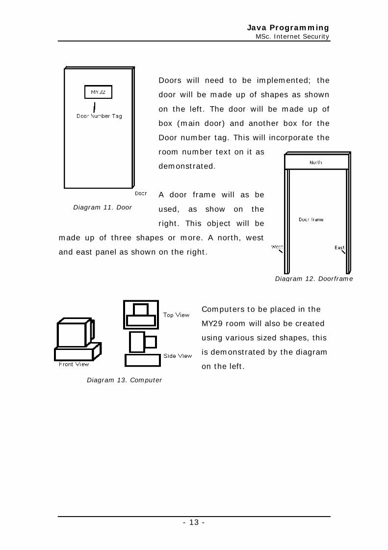
Doors will need to be implemented; the
door will be made up of shapes as shown
on the left. The door will be made up of
box (main door) and another box for the
Door number tag. This will incorporate the
room number text on it as
demonstrated.
A door frame will as be
used, as show on the
right. This object will be
made up of three shapes or more. A north, west
and east panel as shown on the right.
Computers to be placed in the
MY29 room will also be created
using various sized shapes, this
is demonstrated by the diagram
on the left.
Diagram 11. Door
Diagram 12. Doorframe
Diagram 13. Computer
Java Programming MSc. Internet Security
- 14 -
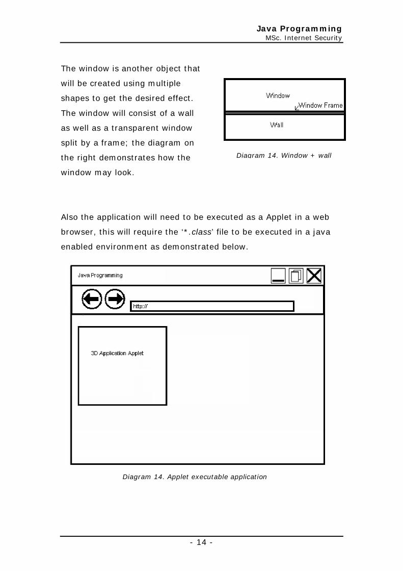
The window is another object that
will be created using multiple
shapes to get the desired effect.
The window will consist of a wall
as well as a transparent window
split by a frame; the diagram on
the right demonstrates how the
window may look.
Also the application will need to be executed as a Applet in a web
browser, this will require the ‘*.class’ file to be executed in a java
enabled environment as demonstrated below.
Diagram 14. Window + wall
Diagram 14. Applet executable application

Java Programming MSc. Internet Security
- 15 -
Flow chart
Start
3D Application initialized with
Icon, Menu Bar, Title etc
3D shapes loaded into application
User menu
selection made?
Exit menu item selection made?
User attempt to
move in 3D universe?
Move 3D environment
End
Yes
Yes

Java Programming MSc. Internet Security
- 16 -
super("Java 3D Graphics Application");
Implementation
The first requirement of the investigation was to produce a ‘JFrame’
application which will be used to display graphical objects. A
‘Canvas3D’ was also added to the ‘JFrame’ so that it was possible to
add 3D objects to this application. The ‘Canvas3D’ was then added
to the ‘Locale’ which in turn will be added to the ‘VirtualUniverse’;
this is demonstrated below.
This application was then set up with an application title
demonstrated above in the diagram. The Code on the right below
was implemented into the application to add this feature.
Application Title
Diagram 15. Canvas3D added to an ‘JFrame’ application

Java Programming MSc. Internet Security
- 17 -
CODE REMOVED _ SORRY!
Icon
A customized icon for the application was implemented to give the
application its own unique look and feel. The code below
demonstrates what was implemented into the application to achieve
this.
Application Size
The application was set to a default size on start up; this meant that
when ever the application was loaded the size of the application
would be a set size unless altered by the user. This is demonstrated
by the code on the right.
Center Application
This 3D application
will be centered to
the screen each time
it is to be loaded. The
code below shows
how the application
finds the dimensions
from the screen and
then calculates the center of the screen from which it will places the
program in the center. The Dimensions of the application are kept
the same. This means that the application will not start in the top
setSize(500, 500);
CODE REMOVED _ SORRY!
Diagram 16. Icons updated

Java Programming MSc. Internet Security
- 18 -
left hand corner (by default) of the screen and the size of the
application is not altered.
Application Menu bar
A menu bar was to added to the
application. A file menu was added
to the menu bar, with an exit option
shown on the left. With this function,
it was noticed that on the application
load the menu bar did not appear,
but only appeared after the
application was resized etc. This was
due to initially how the application
started; previously the application would be started set to size, then
visibility set to true before the menu method was even call. A
revision to this meant that the application started setting up the
menu methods, icon, setting screen size then setting visibility to
true as a final step; this is demonstrated by the code below as well
as in the diagram.
CODE REMOVED _ SORRY!
CODE REMOVED _ SORRY!
CODE REMOVED _ SORRY!

Java Programming MSc. Internet Security
- 19 -
With this menu bar function implemented, an ‘actionlistener’ was
added to the source code which will enable the application to act on
events like a menu option being selected. The code below
demonstrated the ‘actionlistener’ added for file menu, exit menu
selection.
Look and Feel
The code on the right shows what was
added to the application ‘Main’
method to capture the systems look
and feel. This meant that what ever
operating system environment the
application was running on the
menus, buttons etc wouldn’t look like
it was from other computer settings
(blends in to environment).
CODE REMOVED _ SORRY!
Diagram 17. Menu Bar
CODE REMOVED _ SORRY!
Diagram 16. System Look & Feel
Java Programming MSc. Internet Security
- 20 -
CODE REMOVED _ SORRY!
Object length X axis transform
Y axis transform
Z axis transform
Transform rotate Object height
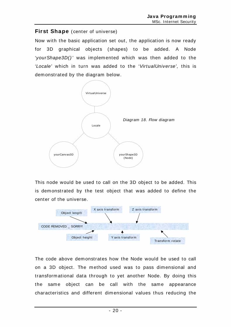
First Shape (center of universe)
Now with the basic application set out, the application is now ready
for 3D graphical objects (shapes) to be added. A Node
‘yourShape3D()’ was implemented which was then added to the
‘Locale’ which in turn was added to the ‘VirtualUniverse’, this is
demonstrated by the diagram below.
This node would be used to call on the 3D object to be added. This
is demonstrated by the test object that was added to define the
center of the universe.
The code above demonstrates how the Node would be used to call
on a 3D object. The method used was to pass dimensional and
transformational data through to yet another Node. By doing this
the same object can be call with the same appearance
characteristics and different dimensional values thus reducing the
VirtualUniverse
Locale
yourCanvas3D
yourShape3D
(Node)
Diagram 18. Flow diagram

Java Programming MSc. Internet Security
- 21 -
amount of unnecessary source code. The code below demonstrated
the function for the object that was implemented.
• The code highlighted ‘1’ shows the colour for the object being
set as red and defined as an appearance.
• The code highlighted ‘2’ shows a Box shape being defined with
values from the variables and the appearance set for this
function.
• The code highlighted ‘3’ defines the rotations of the object
weather it be on the X, Y, or Z axis.
• The code highlighted ‘4’ transforms object to its final
destination which is defined by values inherited from the
previous declaration in the ‘yourShape3D()’ node.
As demonstrated by the code above the function ‘test’ calls and
uses data defined in ‘yourShape()’. Extra variables can be added to
Object length
Object height
X axis transform
Y axis transform
Z axis transform
Transform rotate
CODE REMOVED _ SORRY!
Colour
Rotate object
Move object
Object depth
1
2
3
4

Java Programming MSc. Internet Security
- 22 -
control the colour of the object etc if needed. The diagram below
shows the 3D object created to demonstrate the center of the
Universe.
Diagram 19. Center of the Universe

Java Programming MSc. Internet Security
- 23 -
Keyboard Navigation
This feature was implemented to allow the user to navigate around
objects added to the application. This meant that in true Virtual
Reality the user will be able to navigate around objects and shapes.
The code implemented is shown below was added to the
constructViewBranchGroup branch group which calls on the
yourCanvas3D.
The code highlighted defines where the application starts in the
universe each time loaded.
Adding 3D objects
The next stage was to start adding objects to the canvas, defining
the Maidwell annex building but implementing the lower ground (MB
floor), this later would be pasted to create the 2 upper floors. As
previously, the center of the universe had been mapped out by a
red shape to show where it was; the first object to be added for the
CODE REMOVED _ SORRY!
Sets start point
x – y - z
Java Programming MSc. Internet Security
- 24 -
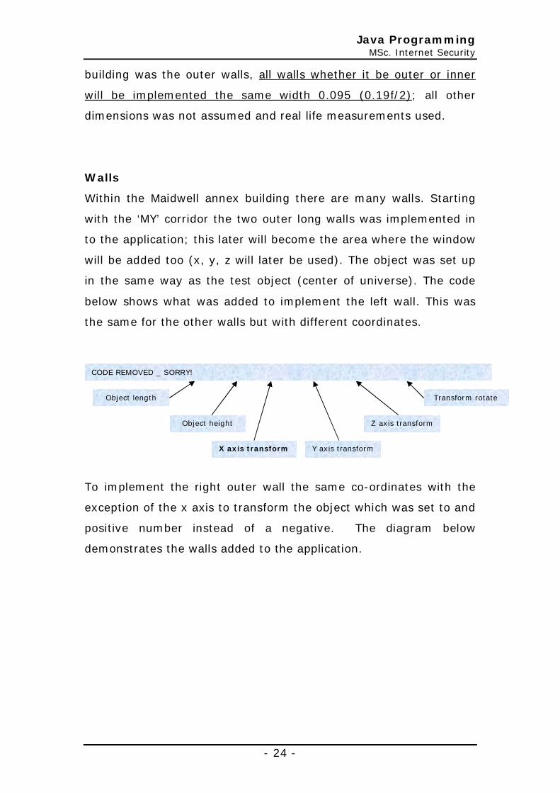
building was the outer walls, all walls whether it be outer or inner
will be implemented the same width 0.095 (0.19f/2); all other
dimensions was not assumed and real life measurements used.
Walls
Within the Maidwell annex building there are many walls. Starting
with the ‘MY’ corridor the two outer long walls was implemented in
to the application; this later will become the area where the window
will be added too (x, y, z will later be used). The object was set up
in the same way as the test object (center of universe). The code
below shows what was added to implement the left wall. This was
the same for the other walls but with different coordinates.
To implement the right outer wall the same co-ordinates with the
exception of the x axis to transform the object which was set to and
positive number instead of a negative. The diagram below
demonstrates the walls added to the application.
Object length
X axis transform
Z axis transform
Transform rotate
Object height
CODE REMOVED _ SORRY!
Y axis transform

Java Programming MSc. Internet Security
- 25 -
The end of corridor (outer) walls for this floor was next to be
implemented; using the co-ordinates acquired from Bevis Matthew
(2004), other walls This is demonstrated by the diagram on the
next page.
Diagram 20. Outer walls added
Diagram 21. adding end walls
CODE REMOVED _ SORRY!

Java Programming MSc. Internet Security
- 26 -
The diagram above demonstrates front walls for the corridor being
added to the application using a test node hence the colour red to
highlight the placement of the shape making sure of no over lapping
& errors in co-ordinates.
The diagram on the left demonstrates
the inner corridor walls being added to
the Maidwell annex building using the
same method as adding the object for
the center of the universe (virtual
canvas)
As demonstrated by the
diagram on the right, the
inner walls for the Maidwell
annex building was
implemented into the
application to separate the
rooms for the floors.
As demonstrated by the
diagram on the right the
building wall sits on the zero X
axis shown by the center of
universe shape; this was to
aid the placement of the walls for the Maidwell annex building.
it was noticed that due some strange anomaly the walls not lining
up as expected coming up to the center of the universe (test shape
Diagram 22. Corridor walls
Diagram 23. Adding inner walls between rooms

Java Programming MSc. Internet Security
- 27 -
shown in diagram 20). As the walls had been placed from farthest
away towards zero on the x, y & z axis and an assumption made of
the walls width (0.19f/2) this could have been the result of this
issue where an overall gap occurred; the diagram below
demonstrates this issue.
With all the walls added to the floor
an indent needed to be created for
the exit/stairs and room 26. These
rooms were half the size of the
other north rooms (to the outer
wall) as a result the diagram on the
left demonstrates the outcome off
the amendments made to values
already assigned.
Diagram 24. Issues with wall dimension
Diagram 25. Indented outer wall for room 26 + exit
Java Programming MSc. Internet Security
- 28 -
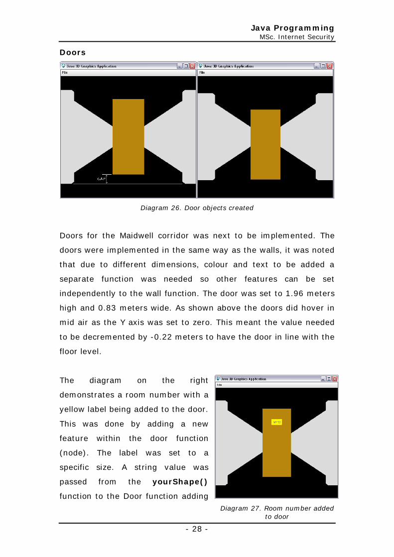
Doors
Diagram 26. Door objects created
Doors for the Maidwell corridor was next to be implemented. The
doors were implemented in the same way as the walls, it was noted
that due to different dimensions, colour and text to be added a
separate function was needed so other features can be set
independently to the wall function. The door was set to 1.96 meters
high and 0.83 meters wide. As shown above the doors did hover in
mid air as the Y axis was set to zero. This meant the value needed
to be decremented by -0.22 meters to have the door in line with the
floor level.
The diagram on the right
demonstrates a room number with a
yellow label being added to the door.
This was done by adding a new
feature within the door function
(node). The label was set to a
specific size. A string value was
passed from the yourShape()
function to the Door function adding
Diagram 27. Room number added to door

Java Programming MSc. Internet Security
- 29 -
the door number using Text2D. The code below demonstrates what
was added for this feature.
Label and Text was then moved using Transform3D; this was then
added to the Transform group of the door so that when the door
was moved the label and the text would move with it as one object.
As this has all been added to a function, it can be called over and
over again passing different x, y & z positioning values along with
the room number.
Door Frame
Next to be implemented after the door was the door frame itself.
This was to be made up of objects that would fit snuggly around the
door. This object was implemented with its own function so that the
door and doorframe would be able to be placed and coloured
independently.
The door frame was made up of a total of three shapes all with a
0.05 meter thick frame. This included a North, East and West
shape. The North shape is 0.90 meters wide and 0.4 meters high.
The East and West shapes have a height 1.96 meters and 0.03 wide
demonstrated by the code below. These shapes are made up of
box’s which was transformed (moved) to there location to fit around
the door. These shapes was then added to yet another transform
group which ultimately defined where the frame as a whole object
would be placed.
CODE REMOVED _ SORRY!
CODE REMOVED _ SORRY!
Java Programming MSc. Internet Security
- 30 -
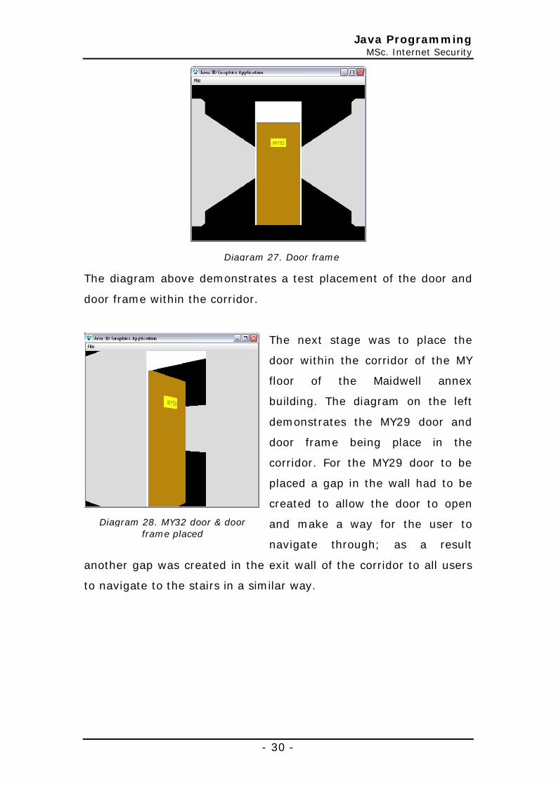
The diagram above demonstrates a test placement of the door and
door frame within the corridor.
The next stage was to place the
door within the corridor of the MY
floor of the Maidwell annex
building. The diagram on the left
demonstrates the MY29 door and
door frame being place in the
corridor. For the MY29 door to be
placed a gap in the wall had to be
created to allow the door to open
and make a way for the user to
navigate through; as a result
another gap was created in the exit wall of the corridor to all users
to navigate to the stairs in a similar way.
Diagram 27. Door frame
Diagram 28. MY32 door & door frame placed

Java Programming MSc. Internet Security
- 31 -
All the other doors were then placed in the corridor; due to the
other rooms having no interaction within application, the door and
door frames were placed on top of the inner corridor wall. Shown
below is a snippet of code from yourShape3D() which adds the
MY30 door to the application.
Diagram 29. Doors added to Maidwell
annex corridor
On the left the diagram
demonstrates all the doors being
added to the corridor with the
exception of the toilet door and the
end wall at end of the corridor.
Diagram 30. Toilet door, wall and cupboard
door added
The toilet, cupboard doors and wall
was next added to the corridor. The
same functions used to place the
other doors and walls were used
shown on the right.
CODE REMOVED _ SORRY!

Java Programming MSc. Internet Security
- 32 -
MY29 Table
Next the tables were defined to be
placed in room MY29. This meant
another function (node) had to be
implemented to add this object. This
function was similar to the wall
function (node) implemented
previously. To differentiate the object
while being implemented (test
purposes) the shape had been
coloured a cyan colour which will be updated later. The code below
shows what was added to yourShape() along with the dimensions
and co-ordinates for three tables joined together to form an ‘n’
layout.
Next the legs for the table were to added to the table. This required
another function (node) to set up its own independent colour and
dimensions. This is demonstrated by the code added to
‘yourShape()’ and the diagram below.
CODE REMOVED _ SORRY!
CODE REMOVED _ SORRY!
Diagram 28. Table added to MY29

Java Programming MSc. Internet Security
- 33 -
MY29 Bench
The computer bench in the MY29 room
was next to be added; this would be
what the computers will be placed on
later. This object was implemented
using the same function as used when
creating a table. The diagram on the
right demonstrates the outcome of the
implemented code (code shown below).
Now with the bench added, the legs needed to be implemented into
the application. This was done in the same was as the table legs
were implemented. The same function was used to add this feature.
The implemented code and result is demonstrated below.
CODE REMOVED _ SORRY!
CODE REMOVED _ SORRY!
Diagram 29. Legs added to table
Diagram 30. Bench for MY29

Java Programming MSc. Internet Security
- 34 -
Window
A window was next to be implemented to the Maidwell Annex
building which will partially remove the outer wall for the north and
south of the building. This will require its own function to specify
dimensions as well as colour to the shape. The windows and outer
wall of the South side building was 6.355 meter wide and 1.3meters
high with a thickness of 0.005 meters. A frame function was also
required to separate the window and wall, an off set of 0.09f was
implemented to allow for this.
The window was implemented with transparency so the user
navigating thought the 3D build would be able to look out the
window. The code below demonstrates what was added to the
function to achieve this.
Diagram 31. Legs added to bench
CODE REMOVED _ SORRY!
Java Programming MSc. Internet Security
- 35 -
Once the main window (and wall) function was set up so that the
two objects window and wall would move and rotate together, it
was then called by ‘for loop’ which demonstrates the z transform
position of the object would be incremented by 6.355f to place the
windows and outer walls to the south side of the building; this is
demonstrated by the code below which also shows a
‘System.out.println(p);’ statement used to track the number of
windows added.
Next the outer windows and walls needed to be added to the north
side of the building, with indented rooms on the north side a row of
windows and walls was not possible like on the south side. This
meant a number of conditions needed to be created to obtain the
desired effect of placing the window and walls for the north side of
the building. This meant another ‘for loop’ was implemented similar
to code for the south side windows and wall shown above. This
meant for debugging purposes it was easy to see how the windows
and walls that was placed; the code below demonstrates what was
implemented in to the application for the north side windows and
walls.
CODE REMOVED _ SORRY!

Java Programming MSc. Internet Security
- 36 -
The screen shots below demonstrate the outcome of the
implemented code.
CODE REMOVED _ SORRY!
Values set up for indented windows
Diagram 32. Outer windows and walls on south & north side
Java Programming MSc. Internet Security
- 37 -
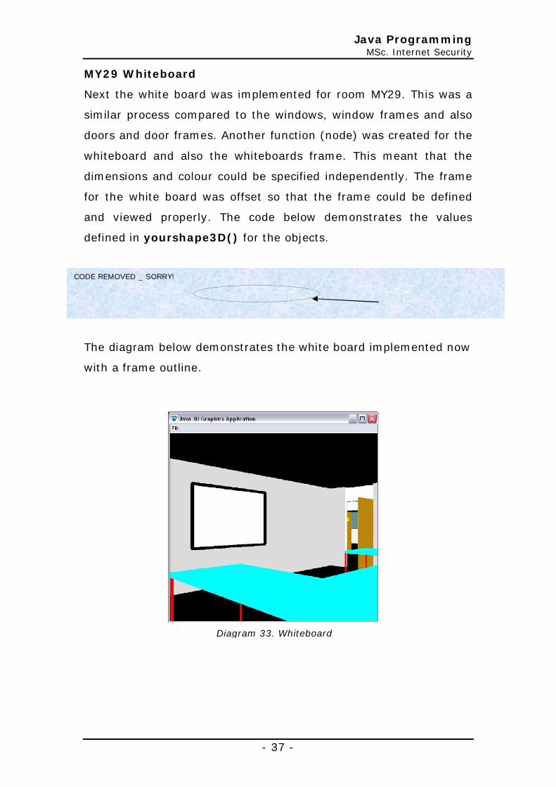
MY29 Whiteboard
Next the white board was implemented for room MY29. This was a
similar process compared to the windows, window frames and also
doors and door frames. Another function (node) was created for the
whiteboard and also the whiteboards frame. This meant that the
dimensions and colour could be specified independently. The frame
for the white board was offset so that the frame could be defined
and viewed properly. The code below demonstrates the values
defined in yourshape3D() for the objects.
The diagram below demonstrates the white board implemented now
with a frame outline.
CODE REMOVED _ SORRY!
Diagram 33. Whiteboard

Java Programming MSc. Internet Security
- 38 -
Computers for MY29
The next stage was to add computers to the
MY29 room. These computers will be
implemented in the same way as door
frame, with multiple shapes being moved as
one shape. The computer implemented
shown on the right consists of three shapes
shown below.
At this stage two colour tones was used to set up the computer. The
three shapes are transformed using different groups for each shape
which then is added to another transform group which allows the
shape as one (made up of the three shapes) to be moved, similar to
the doorframe previously implemented. The diagram below
demonstrates the computers added to the room.
CODE REMOVED _ SORRY!
Diagram 34. Computer for MY29
Diagram 35. Computers added to MY29

Java Programming MSc. Internet Security
- 39 -
MY29 Lights
The next stage was to add ceiling tube lights to MY29. There are six
tube lights in MY29. To implement this feature a new function was
added to the application; this was called Lights. The function
contains an appearance section which colours the shape; a
transform section is implemented to set the axis to rotate on, and
then another transform function to finally place the shape to its final
destination (similar to other functions implemented). The code
below shows the six lights set up using a ‘for loop’ which was an
alternative coding method used instead of using multiple lines of
code just to reposition shapes.
Code which replaced by ‘for loop’
The diagram below demonstrates this feature added to the
application.
CODE REMOVED _ SORRY!
Dimensions for shape, Length, height & width X, Y, Z positions
CODE REMOVED _ SORRY!
lightZco + lightXco values change once condition met (resets and starts other row of lights)

Java Programming MSc. Internet Security
- 40 -
The corridor lights was implemented in a similar way to the light
that are using a ‘for loop’ in MY29, with the use of the same
function, the dimensions of the lights themselves was changed to
1.016f/2 in length and width along with a thickness of 0.1f/2; the X,
Y and Z co-ordinates had to be changed to position the corridor
lights; shown below is the code used and a diagram demonstrating
the outcome.
Diagram 36. Lights added to MY29
CODE REMOVED _ SORRY!
Dimensions for shape, Length, height & width X, Y, Z positions
lightZco + lightXco values change once condition met (resets and starts other row of lights)

Java Programming MSc. Internet Security
- 41 -
Object Loader
Next a pre-defined object was loaded into a 3D application using the
object loader, looking at Gary Hill (2004) an objected was loaded
from a *.obj file which is demonstrated by diagram below showing
an object file acquired from Computer Graphics (2001).
Diagram 41. Demonstrating Object files.
Diagram 36. Lights added to corridor

Java Programming MSc. Internet Security
- 42 -
The code below was to add the object image to yourShape3D().
Animation
After the implementation of the image (object file) in to the 3D
application, the animation of the image was next to be added. After
reading Palmer, I (2001) on animation it was decided to create a
new function ‘anniShuttle()’ to rotate and transform the image
(minimize code); the code above demonstrates the X, Y, and Z
values passed to transform below center of rotation plus rotation
angle.
Shown below is the code implemented in to the ‘anniShuttle()’
function; this function loads the object shape from the file, then like
other functions previously implemented, the object is rotated and
transformed (shown in section 1)
CODE REMOVED _ SORRY!
CODE REMOVED _ SORRY!

Java Programming MSc. Internet Security
- 43 -
Section 2 demonstrates another transform function used to animate
the object; this uses Alpha values to control the interpolator
process. Above in the code the ‘Alpha’ values are highlighted in red;
below the code explains the values changed from default.
CODE REMOVED _ SORRY!
Object imported from file
Rotate and transform image
2
1

Java Programming MSc. Internet Security
- 44 -
The screen shot below demonstrates the use of animation in an 3D
environment.
Additional building floors
Now with a virtual MY corridor demonstrated in the application with
tables, computers, bench’s, lights etc the upper and lower floors
needed to be added to the building. A ‘for loop’ was
implemented (show on the right) around shapes
needing to be duplicated to floor MB, MY and MR for
example walls, window, door, door frames etc.
Using an incremented float value ‘yCo’ in the Y transform position
meant that on each loop (of the for loop) the shape will be moved
along the Y axis as required, the Y axis was implemented with a
2.59 rise. The code below demonstrates the changes made to a
shape already declared.
CODE REMOVED _ SORRY!
Loops animation for infinity Loop cycle for animation set to
6sec’s
Diagram 41. Animated imported object
CODE REMOVED _
SORRY!
Java Programming MSc. Internet Security
- 45 -
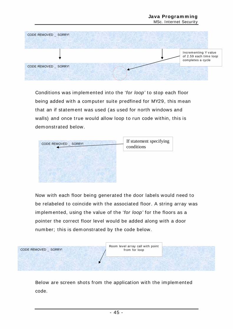
Conditions was implemented into the ‘for loop’ to stop each floor
being added with a computer suite predfined for MY29, this mean
that an if statement was used (as used for north windows and
walls) and once true would allow loop to run code within, this is
demonstrated below.
Now with each floor being generated the door labels would need to
be relabeled to coincide with the associated floor. A string array was
implemented, using the value of the ‘for loop’ for the floors as a
pointer the correct floor level would be added along with a door
number; this is demonstrated by the code below.
Below are screen shots from the application with the implemented
code.
CODE REMOVED _ SORRY!
CODE REMOVED _ SORRY!
Incrementing Y value of 2.59 each time loop completes a cycle
CODE REMOVED _ SORRY!
If statement specifying conditions
CODE REMOVED _ SORRY!
Room level array call with point from for loop

Java Programming MSc. Internet Security
- 46 -
Diagram 41. MB, MY and MR floors added

Java Programming MSc. Internet Security
- 47 -
Floor and Ceiling
For the floor and ceiling another function was created due to the
multiple (box) shapes being combined to form one object; the top
shape formed the floor and bottom half was the ceiling; below
shows the code added.
The shape dimensions and X, Y and Z positions are passed to the
floor function; the outcome is shown below.
Textural effects was added to the shapes making up the floor and
ceiling to given the building a unique look. After reading notes from
Gary Hill (2004), the code below was added for the floor to import a
picture file.
CODE REMOVED _ SORRY!
Diagram 41. Floor and Ceiling added
between MB, MY and MR floors
CODE REMOVED _ SORRY!
Java Programming MSc. Internet Security
- 48 -
Stairs
The stairs was implemented using a new function to define unique
properties whether it be colour or dimension; with a new function
implemented values for positioning on the X, Y and Z axis was
achieved for each flight of stairs. A ‘for loop’ was used to implement
the stairs with multiple steps each offset to each other using
incrementing values; below shows the code added.
With the stairs added to the Maidwell building, conditions (shown
next to 1) was defined so the stairs don’t appear to carry on
through the roof of the building. The stairs was set to half the exit
room width. From the ground floor up two sets of stair was needed
to get to each level; shown below is the code added for floors
between the stairs.
CODE REMOVED _ SORRY!
1

Java Programming MSc. Internet Security
- 49 -
The diagram below demonstrates the stairs being added, the
windows for the north side of the building was removed
(temporarily) to show the added feature.
CODE REMOVED _ SORRY!
Diagram 41. Stairs and floors added
between stairs

Java Programming MSc. Internet Security
- 50 -
Collision Detection
After reading notes from Gary Hill (2004), this feature and addition
button navigation function was added to the application; the
buttons added was –
§ Forward
§ Backward
§ Left
§ Right
§ Up (level)
§ Down (level)
Borderlayout was used to separate the button navigation (set to
south) from the main window (set to center); this method was also
used to place the buttons in the south panel. ‘actionlisteners’ was
added to act on any events that occurred as a result of user
selection, demonstrated below is the code implemented for the
forward button.
CODE REMOVED _ SORRY!
Move -1 on Z axis
Condition monitors Z position, once condition is met and message appears

Java Programming MSc. Internet Security
- 51 -
As demonstrated above, once the Z axis position condition is true in
the actionlisterner the application will bring up a prompt not
allowing to move on further.
Colouring
The next stage was adding colouring
to the shapes implemented within the
application that have not been
rendered. With shapes implemented,
appearances for the shape can be
added, this gave the shape its colour
etc. Looking at Gary Hill (2004),
“RGB colour values from 0 to 1
(decimal)” website, addition colours
was acquired; the diagram on the
right demonstrates the changes made to the application.
Diagram 41. Collision detection
Z Axis position
Diagram 37. Colours Added
Java Programming MSc. Internet Security
- 52 -
Light Shading
Lighting and shading effects was next to be incorporated in to the
application; the function ‘addLights’ was implemented to the
application which as will set the behavior of an object when lighting
is applied to the surrounding area. This is demonstrated by the code
below which as implemented after reading Palmer I (2001).
The code above was added to emulate the lighting coming in from
windows and light shining from the light strip. The following
highlighted code below was implemented in to the application to
add the light and shading effect.
CODE REMOVED _ SORRY!
Lighting set to ‘boundingsphere’
Light colour set
Light direction set

Java Programming MSc. Internet Security
- 53 -
Within the functions that required lighting and shading effects the
follow code below was implemented which would allow the lighting
and shading to influence the object in the application. As an
example the code below is demonstrated on the computers added
to MY29 (previously implemented).
It was noticed that in when implementing this feature that
‘Box.GENERATE_TEXTURE_COORDS’ wouldn’t allow cast shading on
an object or shape added to the virtual universe. This was over
come by removing this as demonstrated below.
CODE REMOVED _ SORRY!
CODE REMOVED _ SORRY!
CODE REMOVED _ SORRY!
After
Before
Diagram 37. Lighting issues

Java Programming MSc. Internet Security
- 54 -
The diagram below demonstrates the outcome out this feature after
the issues with shading and lighting was resolved.
User Defined Geometry
Within the application, a shape
was implemented to
demonstrate that shapes
(objects) can be created with
defined geometry. A new
function was created to hold
the code which meant the
shape could be created over
and over again placing where
ever defined. The code on the
right demonstrates the co-
ordinates and indices declared
in the function.
Initially using the User defined geometry method a project for MY29
was to be created, due to time restraints a simple square was
added outside the building as shown below.
Diagram 37. Lighting added to Maidwell Annex building
CODE REMOVED _ SORRY!

Java Programming MSc. Internet Security
- 55 -
Converting to JApplet
As specified in the requirements of this application needed to be
converted to a ‘JApplet’ from a ‘JFrame’ application. This meant that
the application changed allowing it to be executed on a web browser
that is java enabled. After reading though notes on Gary Hill (2006)
website, the code below was implemented to demonstrate a simple
.html file created to demonstrate the application.
Now with a functioning HTML file to view the application, another
version of the source code needed to be developed for the ‘JApplet’.
Diagram 37. User defined geometry
CODE REMOVED _ SORRY!

Java Programming MSc. Internet Security
- 56 -
Within the source code for the ‘JApplet’ application the following
changes was made to add this feature.
1. Within the public declaration JApplet needed to be declared
instead of JFrame
2. Next the Super declaration for the title of the JFrame was
removed as not needed for the JApplet.
3. pack() which sets the JFrame was removed.
4. From the ’main’ function the following code was removed
which make sure JFrame was closed upon exit.
5. The following code was removed from the actionlistener of the
Exit item found in the File menu.
There were a few issues while implementing the application to run
as a JApplet, images couldn’t be imported as in the JFrame
application; functions using images etc was removed from the
JApplet to compile JApplet application. The screen show
demonstrates the outcome of the JApplet.
CODE REMOVED _ SORRY!
CODE REMOVED _ SORRY!
CODE
CODE REMOVED _ SORRY!
CODE REMOVED _ SORRY!

Java Programming MSc. Internet Security
- 57 -
Diagram 37. JApplet 3D Application

Java Programming MSc. Internet Security
- 58 -
Testing
Testing was continuously carried out during the development of this
3D application. This means that any problems that had arisen had
been fixed of worked around. The aim of the final testing is to make
sure that the development of the application works correctly and
meets all criteria that were set for this investigation.
Test
Test Description Result Comment
JFrame Application Test
Load Application
Application Loads in normal 500x500 mode ü Very slow on old computers.
Load Application
Application Loads and can be resized to max then normal again
ü --
Application Icon
Application Loads icon on execution ü --
Application Title
Application Loads title on execution ü --
Virtual Universe
Virtual universe should appear on the application ü --
Menu bar appears
On start up menu bar appears ü
Floor’s, corridor’s and rooms rendered to size given on the floor.
Dimensions for the Floor’s, corridor’s and rooms are the same
ü --
Walls, floor/s and ceiling/s should all 'look' different.
All shapes in the application should have a different look
ü --
Benching rendered in MY29.
The computer bench in MY29 to be rendered ü --
Horizontal navigation
(back, forward, left and right) ü --
size of MY29 (Width 6250mm* Length 7550mm * Height 3150mm).
Size of MY29 set to (Width 6270mm* Length 7600mm * Height 3150mm).
ü --
Doors, windows, strip lights, tables, and computers rendered in MY29
All shapes images were rendered in MY29 ü --

Java Programming MSc. Internet Security
- 59 -
surfaces defined and rendered as a material or given a texture
Floor and ceiling appeared with textures ü --
Incorporation of lighting effect
Computers, tables, bench, walls white board frame in MY29 appeared with shading.
ü --
User defined geometry (i.e. not primitive shapes).
added behind building z = -40 ü --
Loaded geometry using object files
added behind building z = -80 ü --
The corridor and rooms should be navigable.
Navigable using keyboard ü --
Navigation using buttons and/or keyboard
Using keyboard, buttons fully working ü --
Collision detection.
Added using button to end of corridor. ü --
Animation Shuttle animated ü --
JApplet application Test
Load Application
Application Loads in normal 500x500 mode ü Java + Java 3D codec needed on computer
Load Application
Application Loads and can be resized to max then normal again
ü --
Application Icon
Application Loads icon on execution ý Code removed due to import image issues
Virtual Universe
Virtual universe should appear on the application ü --
Menu bar appears
On start up menu bar appears ý File – exit doesn’t work as not JFrame Application, Help menu works ok.
Floor’s, corridor’s and rooms rendered to size given on the floor.
Dimensions for the Floor’s, corridor’s and rooms are the same
ü --
Walls, floor/s and ceiling/s should all 'look' different.
All shapes in the application should have a different look
ü --
Benching rendered in MY29.
The computer bench in MY29 to be rendered ü --
Horizontal navigation
(back, forward, left and right) ü --
size of MY29 (Width 6250mm* Length 7550mm *
Size of MY29 set to (Width 6270mm* Length 7600mm * Height 3150mm).
ü --

Java Programming MSc. Internet Security
- 60 -
Height 3150mm).
Doors, windows, strip lights, tables, and computers rendered in MY29
All shapes images were rendered in MY29 ü --
surfaces defined and rendered as a material or given a texture
Floor and ceiling appeared with textures ü --
Incorporation of lighting effect
Computers, tables, bench, walls white board frame in MY29 appeared with shading.
ü --
User defined geometry (i.e. not primitive shapes).
added behind building z = -40 ü --
Loaded geometry using object files
added behind building z = -80 ü --
The corridor and rooms should be navigable.
Navigable using keyboard ü --
Navigation using buttons and/or keyboard
Using keyboard, buttons fully working ü --
Collision detection.
Added using button to end of corridor. ü --
Animation Shuttle animated ý Code removed due to import image issues
The table above has been created to show any errors of problems in
the 3D application & JApplet that may arise.
The test carried out in the table above had been with 2 non IT
students who are IT literate. They have been given the code and
tested the program not necessarily in the order that it is stated
above in the table. The outcome was that the result was just the
same as the one shown above in the table. It was noticed that the
performance on different machine varied from be clumsy and jerky
when navigating, to being too fast and hard to control when the
detail was increased with ‘+’ and ‘-‘ buttons on the keyboard. One
Java Programming MSc. Internet Security
- 61 -
of the students did pickup on the fact that the lighting and shading
varied as the MY29 room was navigated.
Also when the JApplet application was tested, one student had
issues with the computer that was being used. This meant that
another computer with correctly version of Java 3D API installed
had to be used. It was noticed by the students that the animated
shuttle was missing and the File – Exit menu selection didn’t
function.

Java Programming MSc. Internet Security
- 62 -
Finished application
The diagrams below demonstrate the finished application that was
implemented
Diagram 44. Doors
Diagram 42. Corridor Diagram 43. MY32
Diagram 45. Corridors Lights

Java Programming MSc. Internet Security
- 63 -
Diagram 46. M29 Room Diagram 46. White board in MY29
Diagram 46. North view Maidwell building
Diagram 46. South view Maidwell building

Java Programming MSc. Internet Security
- 64 -
Diagram 37. JApplet 3D Application
Diagram 37. JApplet 3D Application 2

Java Programming MSc. Internet Security
- 65 -
Conclusion & recommendation
To conclude this report, all criteria have been met during this
investigation.
Given more time, the additional shapes would have been added to
the 3D application for example a rotating sky to assist with the
virtual universe effect.
The MY29 room was implemented with furniture, but did not include
chairs. Given more time more Objects would have been loaded
using the object loader function. This would have given a greater
depth and realism to application.
With the menu bar added to the application a problem was noticed
when loaded. The menu bar appeared to sit behind the canvas 3D
until the application was resized. This was resolved and cause was
due to the order which method was being called and initialized in
the application.
Issues were encountered during the implementation of this
application, as follows:
1. Measurements acquired from Bevins Mathews (2004). This
left a space towards zero on the x axis. This space was
blocked off and all the rooms were implemented to size. This
anomaly was put down to assumptions made on the wall
thickness.
2. Lighting in the application. An issue with the use of
‘Box.GENERATE_TEXTURE_COORDS’ meant the object or
shape wouldn’t be lighten as required so it was removed.

Java Programming MSc. Internet Security
- 66 -
The use of animation within the application was very interesting and
added a detailed touch to the application; with more time the
animation of moving clouds would have added giving the ultimate
effect for the application.
Collision detection was only demonstrated to one area within the
application, with more time extra conditions would have been
created to aid with the user’s navigation. This could have been
combined with animation and implemented to the doors to open
when approached etc (animation could have been added to open
door with collision detection too).
During the implementation of the JApplet from the JFrame
application a few problems was encountered.
The 1st problem was that for some reason images (icon + object
file) imported brought up errors. The icon error was expected being
an Web Applet and not a normal application. As soon as the code
was commented out of the JApplet version of the application it
executed on the web browser.
The 2nd problem was that exit item in the file menu wouldn’t exit,
this may be down to the application compiled as a JApplet and the
feature no longer being available. Given more time these problems
would have been resolved.
All criteria for this application were met, given more time other
shapes, object, and complexity would have been added to the
application, for example the completion of the projector shape using
user defined geometry would have been fully implemented.

Java Programming MSc. Internet Security
- 67 -
Additional Features included are -
§ Doors, windows, strip lights, tables, chairs and computers
rendered in MY29.
§ Doors, windows, walls, roof rendered to the exterior of the
Maidwell Building.
§ The surfaces defined and rendered as a material or given a
texture.
§ Incorporation of lighting effect using material, ambient,
directional, point and spot lighting (to model windows and/or
strip lights).
§ User defined geometry (i.e. not primitive shapes).
§ Loaded geometry using object files e.g. additional items
rendered within the rooms/building or outside.
§ The external environment, floors, stairs, corridor and rooms
should be navigable.
§ Navigation using buttons and/or keyboard and/or mouse.
§ Collision detection.
§ Animation e.g. door/s opening, clouds moving past the
windows.

Java Programming MSc. Internet Security
- 68 -
References
Gary Hill (2006), “SECTION D - JAVA 3D” [online]
http://194.81.104.27/~gary/csy3019/CSY3019SectionD.html
Accessed on the 14th March 2007
Gary Hill (2004), “RGB colour values from 0 to 1 (decimal)”
[online],
http://194.81.104.27/~gary/csy3019/RGB.htm#Full_Index
Accessed on the 14th March 2007
Palmer, I (2001), “Essential Java 3D Fast”, Springer Veriag London
Matthew Bevins (2004), “CSY3019 Graphics Programming” [online],
http://194.81.104.27/~gary/csy3019/20032004/csy3019Ass2report
1.pdf
Accessed on the 14th March 2007
Computer Graphics (2001), “Computer Graphics” [online],
http://www.cs.duke.edu/courses/cps124/fall01/
Accessed on the 15th March 2007

Java Programming MSc. Internet Security
- 69 -
Bibliography
Gary Hill (2006), “SECTION D - JAVA 3D” [online]
http://194.81.104.27/~gary/csy3019/CSY3019SectionD.html
Accessed on the 14th March 2007
Palmer, I (2001), “Essential Java 3D Fast”, Springer Veriag London
Matthew Bevins (2004), “CSY3019 Graphics Programming” [online],
http://194.81.104.27/~gary/csy3019/20032004/csy3019Ass2report
1.pdf
Accessed on the 14th March 2007
Sun Development (1994-2006), “Sun Development Network”
[online],
http://java.sun.com/products/java-media/3D/
Accessed on the 21st March 2007
Computer Graphics (2001), “Computer Graphics” [online],
http://www.cs.duke.edu/courses/cps124/fall01/
Accessed on the 15th March 2007

Java Programming MSc. Internet Security
- 70 -
Appendices


![Hdr 20072008 Presentation[1]](https://static.fdocuments.us/doc/165x107/559a02c91a28abbd5c8b45fb/hdr-20072008-presentation1.jpg)