Table of Contentsv12.dyndns.org/BMW/BMW 7 (E65-66)/08_E65 Brakes.pdfIn the first stage of wear...
33
Table of Contents Subject Page Brakes Objectives of the Module . . . . . . . . . . . . . . . . . . . . . . . . . . . . . . . . . . . . .2 Purpose of the System . . . . . . . . . . . . . . . . . . . . . . . . . . . . . . . . . . . . . . .3 Service Brakes System Components . . . . . . . . . . . . . . . . . . . . . . . . . . . . . . . . . . . . . . . . 4 Front and Rear Calipers . . . . . . . . . . . . . . . . . . . . . . . . . . . . . . . . . . . . . . 4 2 Stage Brake Pad Wear Sensor . . . . . . . . . . . . . . . . . . . . . . . . . . . . . . . . 5 Brake Control. . . . . . . . . . . . . . . . . . . . . . . . . . . . . . . . . . . . . . . . . . . . . . 5 Brake Discs . . . . . . . . . . . . . . . . . . . . . . . . . . . . . . . . . . . . . . . . . . . . . . . 6 Wheel Speed Sensors. . . . . . . . . . . . . . . . . . . . . . . . . . . . . . . . . . . . . . . . 6 Workshop Hints . . . . . . . . . . . . . . . . . . . . . . . . . . . . . . . . . . . . . . . . . . . . 8 Parking Brake (EMF) Purpose of the System. . . . . . . . . . . . . . . . . . . . . . . . . . . . . . . . . . . . . . . 9 Functions . . . . . . . . . . . . . . . . . . . . . . . . . . . . . . . . . . . . . . . . . . . . . . . 10 System Components . . . . . . . . . . . . . . . . . . . . . . . . . . . . . . . . . . . . . . . 11 Electro-mechanical Actuating Unit. . . . . . . . . . . . . . . . . . . . . . . . . . . . . . 12 Emergency Release . . . . . . . . . . . . . . . . . . . . . . . . . . . . . . . . . . . . . . . . 14 Principle of Operation . . . . . . . . . . . . . . . . . . . . . . . . . . . . . . . . . . . . . . . 16 Safety Concept . . . . . . . . . . . . . . . . . . . . . . . . . . . . . . . . . . . . . . . . . . . 22 EMF Self Diagnostics . . . . . . . . . . . . . . . . . . . . . . . . . . . . . . . . . . . . . . . 25 Workshop Hints . . . . . . . . . . . . . . . . . . . . . . . . . . . . . . . . . . . . . . . . . . . 26 Check Control and Control Display Fault Descriptions . . . . . . . . . . . . . . . 28
Transcript of Table of Contentsv12.dyndns.org/BMW/BMW 7 (E65-66)/08_E65 Brakes.pdfIn the first stage of wear...

Table of Contents
Subject Page
BrakesObjectives of the Module . . . . . . . . . . . . . . . . . . . . . . . . . . . . . . . . . . . . .2Purpose of the System . . . . . . . . . . . . . . . . . . . . . . . . . . . . . . . . . . . . . . .3
Service BrakesSystem Components . . . . . . . . . . . . . . . . . . . . . . . . . . . . . . . . . . . . . . . . 4Front and Rear Calipers . . . . . . . . . . . . . . . . . . . . . . . . . . . . . . . . . . . . . . 42 Stage Brake Pad Wear Sensor. . . . . . . . . . . . . . . . . . . . . . . . . . . . . . . . 5Brake Control. . . . . . . . . . . . . . . . . . . . . . . . . . . . . . . . . . . . . . . . . . . . . . 5Brake Discs . . . . . . . . . . . . . . . . . . . . . . . . . . . . . . . . . . . . . . . . . . . . . . . 6Wheel Speed Sensors. . . . . . . . . . . . . . . . . . . . . . . . . . . . . . . . . . . . . . . .6Workshop Hints . . . . . . . . . . . . . . . . . . . . . . . . . . . . . . . . . . . . . . . . . . . .8
Parking Brake (EMF) Purpose of the System. . . . . . . . . . . . . . . . . . . . . . . . . . . . . . . . . . . . . . . 9Functions . . . . . . . . . . . . . . . . . . . . . . . . . . . . . . . . . . . . . . . . . . . . . . . 10System Components . . . . . . . . . . . . . . . . . . . . . . . . . . . . . . . . . . . . . . . 11Electro-mechanical Actuating Unit. . . . . . . . . . . . . . . . . . . . . . . . . . . . . . 12Emergency Release . . . . . . . . . . . . . . . . . . . . . . . . . . . . . . . . . . . . . . . . 14Principle of Operation . . . . . . . . . . . . . . . . . . . . . . . . . . . . . . . . . . . . . . . 16Safety Concept . . . . . . . . . . . . . . . . . . . . . . . . . . . . . . . . . . . . . . . . . . . 22EMF Self Diagnostics . . . . . . . . . . . . . . . . . . . . . . . . . . . . . . . . . . . . . . . 25Workshop Hints . . . . . . . . . . . . . . . . . . . . . . . . . . . . . . . . . . . . . . . . . . . 26Check Control and Control Display Fault Descriptions . . . . . . . . . . . . . . . 28
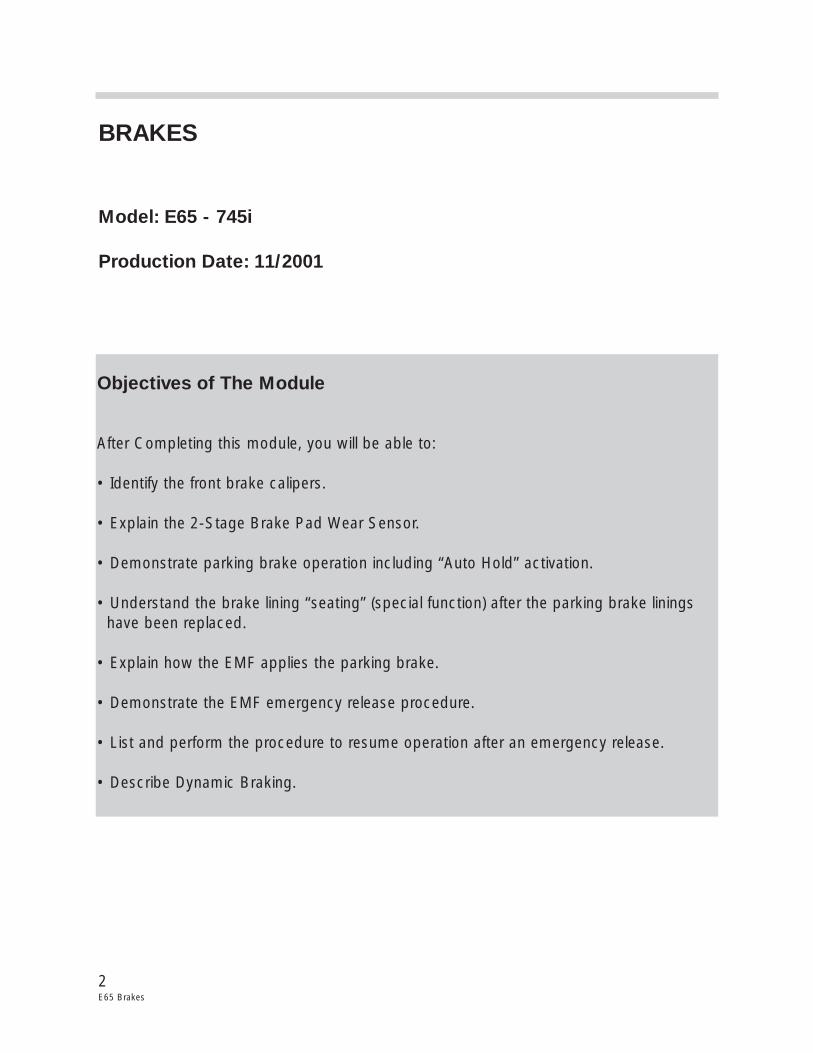
BRAKES
Model: E65 - 745i
Production Date: 11/2001
Objectives of The Module
After Completing this module, you will be able to:
• Identify the front brake calipers.
• Explain the 2-Stage Brake Pad Wear Sensor.
• Demonstrate parking brake operation including “Auto Hold” activation.
• Understand the brake lining “seating” (special function) after the parking brake linings have been replaced.
• Explain how the EMF applies the parking brake.
• Demonstrate the EMF emergency release procedure.
• List and perform the procedure to resume operation after an emergency release.
• Describe Dynamic Braking.
2E65 Brakes
3E65 Brakes
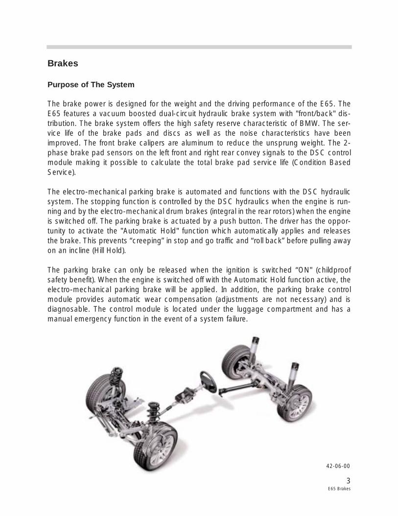
Brakes
Purpose of The System
The brake power is designed for the weight and the driving performance of the E65. TheE65 features a vacuum boosted dual-circuit hydraulic brake system with "front/back" dis-tribution. The brake system offers the high safety reserve characteristic of BMW. The ser-vice life of the brake pads and discs as well as the noise characteristics have beenimproved. The front brake calipers are aluminum to reduce the unsprung weight. The 2-phase brake pad sensors on the left front and right rear convey signals to the DSC controlmodule making it possible to calculate the total brake pad service life (Condition BasedService).
The electro-mechanical parking brake is automated and functions with the DSC hydraulicsystem. The stopping function is controlled by the DSC hydraulics when the engine is run-ning and by the electro-mechanical drum brakes (integral in the rear rotors) when the engineis switched off. The parking brake is actuated by a push button. The driver has the oppor-tunity to activate the "Automatic Hold" function which automatically applies and releasesthe brake. This prevents “creeping” in stop and go traffic and “roll back” before pulling awayon an incline (Hill Hold).
The parking brake can only be released when the ignition is switched “ON" (childproofsafety benefit). When the engine is switched off with the Automatic Hold function active, theelectro-mechanical parking brake will be applied. In addition, the parking brake controlmodule provides automatic wear compensation (adjustments are not necessary) and isdiagnosable. The control module is located under the luggage compartment and has amanual emergency function in the event of a system failure.
42-06-00
4E65 Brakes
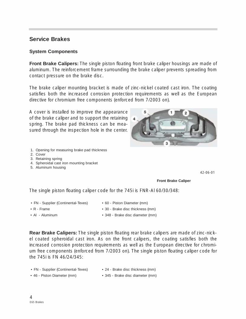
Service Brakes
System Components
Front Brake Calipers: The single piston floating front brake caliper housings are made ofaluminum. The reinforcement frame surrounding the brake caliper prevents spreading fromcontact pressure on the brake disc.
The brake caliper mounting bracket is made of zinc-nickel coated cast iron. The coatingsatisfies both the increased corrosion protection requirements as well as the Europeandirective for chromium free components (enforced from 7/2003 on).
A cover is installed to improve the appearanceof the brake caliper and to support the retainingspring. The brake pad thickness can be mea-sured through the inspection hole in the center.
The single piston floating caliper code for the 745i is FNR-Al 60/30/348:
• FN - Supplier (Continental-Teves) • 60 - Piston Diameter (mm)
• R - Frame • 30 - Brake disc thickness (mm)
• Al - Aluminum • 348 - Brake disc diameter (mm)
Rear Brake Calipers: The single piston floating rear brake calipers are made of zinc-nick-el coated spheroidal cast iron. As on the front calipers, the coating satisfies both theincreased corrosion protection requirements as well as the European directive for chromi-um free components (enforced from 7/2003 on). The single piston floating caliper code forthe 745i is FN 46/24/345:
• FN - Supplier (Continental-Teves) • 24 - Brake disc thickness (mm)
• 46 - Piston Diameter (mm) • 345 - Brake disc diameter (mm)
42-06-01
Front Brake Caliper
1. Opening for measuring brake pad thickness2. Cover3. Retaining spring4. Spheroidal cast iron mounting bracket5. Aluminum housing
5E65 Brakes
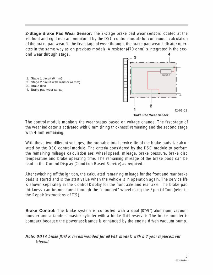
2-Stage Brake Pad Wear Sensor: The 2-stage brake pad wear sensors located at theleft front and right rear are monitored by the DSC control module for continuous calculationof the brake pad wear. In the first stage of wear through, the brake pad wear indicator oper-ates in the same way as on previous models. A resistor (470 ohm) is integrated in the sec-ond wear through stage.
The control module monitors the wear status based on voltage change. The first stage ofthe wear indicator is activated with 6 mm (lining thickness) remaining and the second stagewith 4 mm remaining.
With these two different voltages, the probable total service life of the brake pads is calcu-lated by the DSC control module. The criteria considered by the DSC module to performthe remaining mileage calculation are: wheel speed, mileage, brake pressure, brake disctemperature and brake operating time. The remaining mileage of the brake pads can beread in the Control Display (Condition Based Service) as required.
After switching off the ignition, the calculated remaining mileage for the front and rear brakepads is stored and is the start value when the vehicle is in operation again. The service lifeis shown separately in the Control Display for the front axle and rear axle. The brake padthickness can be measured through the “mounted” wheel using the Special Tool (refer tothe Repair Instructions of TIS).
Brake Control: The brake system is controlled with a dual (8"/9") aluminum vacuumbooster and a tandem master cylinder with a brake fluid reservoir. The brake booster iscompact because the power assistance is enhanced by the engine driven vacuum pump.
NNoottee:: DDOOTT44 bbrraakkee fflluuiidd iiss rreeccoommmmeennddeedd ffoorr aallll EE6655 mmooddeellss wwiitthh aa 22 yyeeaarr rreeppllaacceemmeenntt iinntteerrvvaall..
42-06-02Brake Pad Wear Sensor
1. Stage 1 circuit (6 mm)2. Stage 2 circuit with resistor (4 mm)3. Brake disc4. Brake pad wear sensor
6E65 Brakes
Brake Discs: The E65 is equipped with vented brake discs on the front and rear axle madeof high carbon cast iron. The brake disc surfaces are coated with Geomet to satisfy theincreased corrosion protection requirements as well as the European directive for chromi-um free components (enforced from 7/2003 on).
Geomet is a zinc-aluminum surface coating (microfine scaled surface pattern) that issprayed on and baked at 300 ºC. It is environmentally compatible and features outstand-ing corrosion protection properties. On the friction surface of the discs, the protective coat-ing is worn down without any changes in the coefficient of friction. All other surfaces retainthe corrosion resistant coating over the entire service life.
NNoottee:: AAnn iinniittiiaall ssccrraappiinngg ssoouunndd iiss nnoorrmmaall aanndd wwiillll ddiissaappppeeaarr aafftteerr tthhee ffiirrsstt ffeeww bbrraakkiinngg aappppllii--ccaattiioonnss..
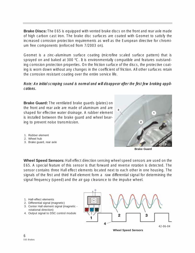
Brake Guard: The ventilated brake guards (plates) onthe front and rear axle are made of aluminum and areshaped for effective water drainage. A rubber elementis installed between the brake guard and wheel bear-ing to prevent noise transmission.
Wheel Speed Sensors: Hall effect direction sensing wheel speed sensors are used on theE65. A special feature of this sensor is that forward and reverse rotation is detected. Thesensor contains three Hall effect elements located next to each other in one housing. Thesignals of the first and third Hall element form a raw differential signal for determining thesignal frequency (speed) and the air gap clearance to the impulse wheel.
42-06-03
Brake Guard
1. Rubber element2. Wheel hub3. Brake guard, rear axle
42-06-04Wheel Speed Sensors
1. Hall-effect elements2. Differential signal (magnetic)3. Center Hall element signal (magnetic -
rotational direction)4. Output signal to DSC control module
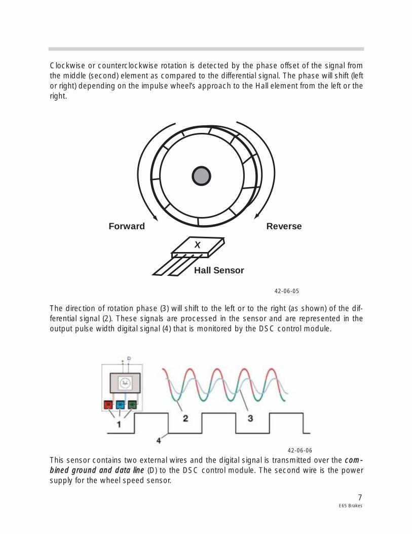
Clockwise or counterclockwise rotation is detected by the phase offset of the signal fromthe middle (second) element as compared to the differential signal. The phase will shift (leftor right) depending on the impulse wheel’s approach to the Hall element from the left or theright.
The direction of rotation phase (3) will shift to the left or to the right (as shown) of the dif-ferential signal (2). These signals are processed in the sensor and are represented in theoutput pulse width digital signal (4) that is monitored by the DSC control module.
This sensor contains two external wires and the digital signal is transmitted over the ccoomm--bbiinneedd ggrroouunndd aanndd ddaattaa lliinnee (D) to the DSC control module. The second wire is the powersupply for the wheel speed sensor.
7E65 Brakes
ReverseForward
Hall Sensor
X
42-06-05
42-06-06
The flow of current is the influencing factor, not the voltage level. This provides a reoccur-ring data message that uses two different amp ratings. The 14 mA level contains the infor-mation of speed, direction of rotation and air gap. The 7 mA level is the evaluation currentfor the fault code memory. When the vehicle is stationary, a pulse is sent every 740 ms tocheck the sensor circuit integrity.
Workshop Hints
The tightening torque requirements of the fastening bolts for the brake hoses have beenchanged (refer to TIS tightening torques).
AAfftteerr rreeppllaacciinngg tthhee bbrraakkee ppaaddss,, tthhee rreessiidduuaall mmiilleeaaggee ssttoorreedd iinn tthhee DDSSCC ccoonnttrrooll mmoodduullee mmuussttbbee rreesseett sseeppaarraatteellyy ffoorr eeaacchh aaxxllee ttoo aa nneeww ssttaarrtt vvaalluuee uussiinngg tthhee DDIISSpplluuss..
WWhheenn tthhee DDSSCC ccoonnttrrooll mmoodduullee iiss rreeppllaacceedd,, tthhee ssppeecciiffiieedd rreemmaaiinniinngg mmiilleeaaggee ffoorr tthhee ffrroonnttaanndd rreeaarr bbrraakkee ppaaddss mmuusstt bbee ttrraannssffeerrrreedd iinnttoo tthhee nneeww DDSSCC ccoonnttrrooll mmoodduullee uussiinngg tthheeDDIISSpplluuss..
NNootteess::
8E65 Brakes
Parking Brake (EMF)
Purpose of The System
The Electro-mechanical Parking Brake (EMF) is used for the first time in series production.The EMF is used to secure a stationary vehicle, preventing it from rolling away by firmlylocking the parking brake. The EMF is an automatic comfort oriented system that replacesthe previous handbrake or foot operated parking brake. The driver can apply and releasethe parking brake by pressing a push button.
The system is designed for the characteristicrequirements of the E65:
• Consideration for safety• Optimum functionality• Maximum system usage• Best comfort and convenience
The Parking Brake push button is located in theinstrument panel to the left of the headlightswitch. The push button is an integral compo-nent of the Light Module.
The EMF mechanically locks theparking brake when the vehicle isstationary and provides an inde-pendent brake system asrequired by law (in addition to theservice brakes).
The EMF system offers addition-al comfort and safety functions.
9E65 Brakes
42-06-06
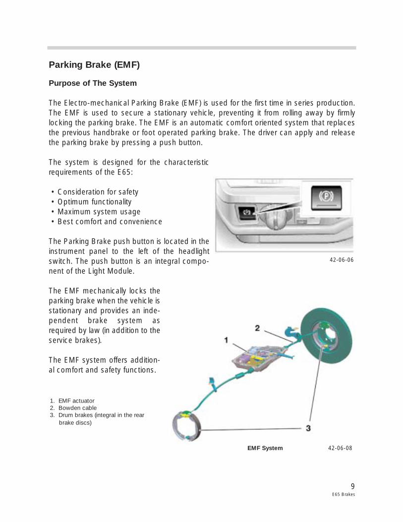
42-06-08EMF System
1. EMF actuator2. Bowden cable3. Drum brakes (integral in the rear
brake discs)
10E65 Brakes
Basic Functions: There are two different parking brake functions depending on the oper-ating status of the vehicle.
LLoocckkiinngg ((BBrraakkee AApppplliieedd))::
• With the engine running or the vehicle rolling, the parking brake function acts on the front and rear axle by the DSC hydraulically applying the service brakes.
• When the engine is not running and the vehicle is stationary, the electro-mechanical parking brake is applied.
DDyynnaammiicc BBrraakkiinngg::
• Braking required to decelerate a moving vehicle is identified by the DSC system when the parking brake push button is pressed while driving. The braking procedure is regu- lated by the DSC hydraulically applying the service brakes and takes place for as long as the push button is pressed.
Automatic Hold: This comfort function is selected using the controller or with the free pro-grammable button on the multifunction steering wheel. After braking to a standstill, thevehicle is held by the DSC hydraulically applying the service brakes. The brakes arereleased by pressing the accelerator pedal. The hold and release function prevents “creep-ing” in stop and go traffic and “roll back” before pulling away on an incline (Hill Hold).
Brake Pedal “Feel”: The response of the brake pedal may change slightly (accompaniedby an activation sound) because the parking brake function is activated using the brakesystem’s hydraulic circuits - this is normal.
Emergency Release: A mechanical emergency release is provided to release the parkingbrake in the event of an actuating unit failure or a dead battery. It is possible to release themechanical actuating parking brake unit using the emergency release tool and an open endwrench found in the vehicle tool kit.
NNoottee:: In addition, refer to the automatic transmission section for the emergency mechani-cal parking lock release procedure.
Special Function: During vehicle operation, brake lining “seating” is conducted at definedintervals to ensure and maintain the effectiveness of the parking brake. The brake liningseating is performed to remove corrosion from the parking brake shoes and brake drums.The procedure automatically takes place approximately every 1000 km or once a monthand is transparent to the driver.
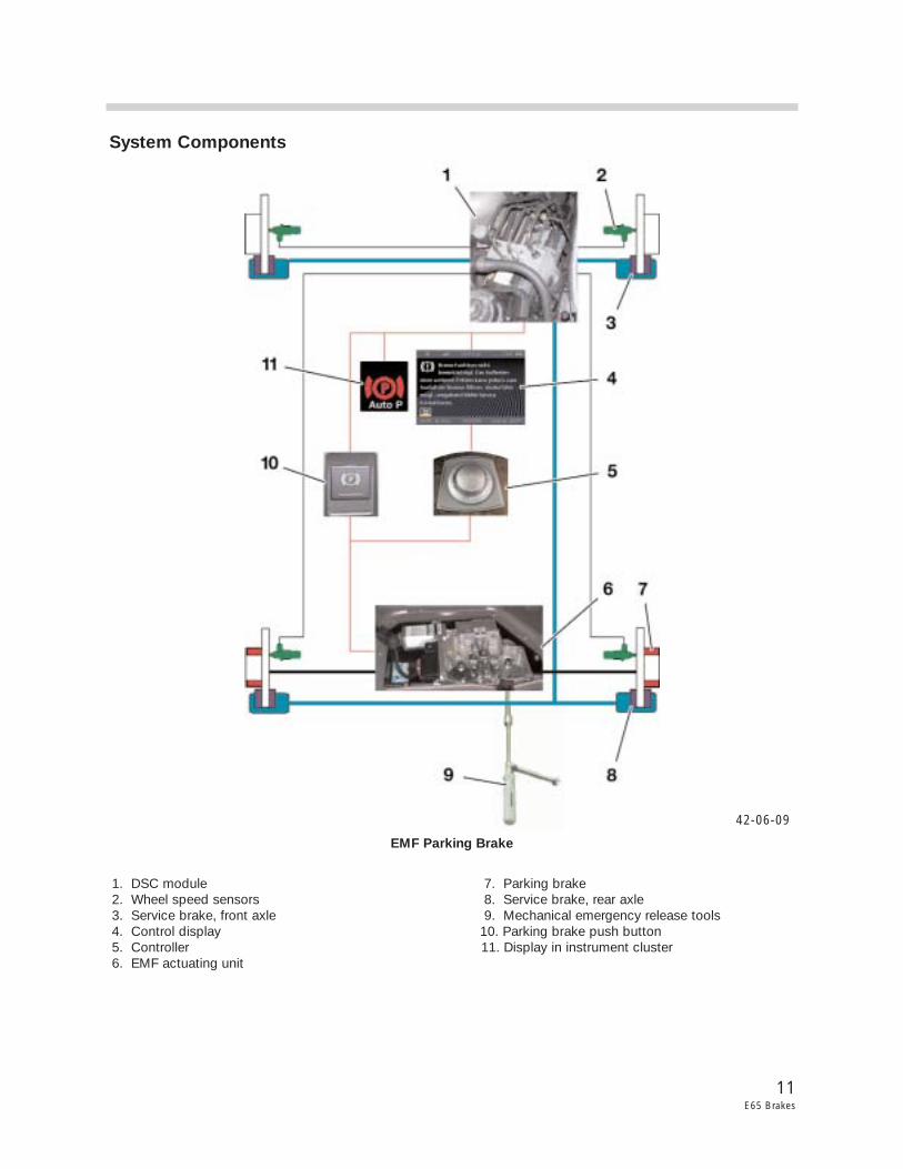
System Components
11E65 Brakes
42-06-09
EMF Parking Brake
1. DSC module 7. Parking brake2. Wheel speed sensors 8. Service brake, rear axle3. Service brake, front axle 9. Mechanical emergency release tools4. Control display 10. Parking brake push button5. Controller 11. Display in instrument cluster6. EMF actuating unit
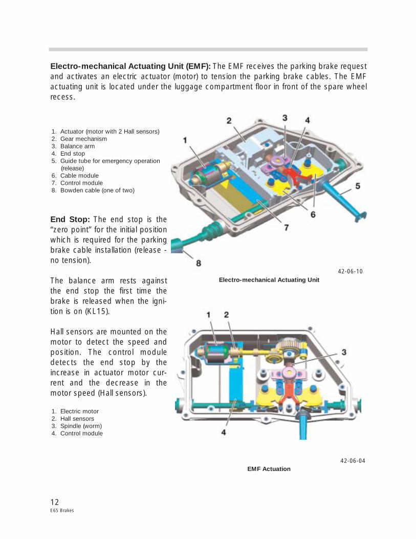
Electro-mechanical Actuating Unit (EMF): The EMF receives the parking brake requestand activates an electric actuator (motor) to tension the parking brake cables. The EMFactuating unit is located under the luggage compartment floor in front of the spare wheelrecess.
End Stop: The end stop is the“zero point” for the initial positionwhich is required for the parkingbrake cable installation (release -no tension).
The balance arm rests againstthe end stop the first time thebrake is released when the igni-tion is on (KL15).
Hall sensors are mounted on themotor to detect the speed andposition. The control moduledetects the end stop by theincrease in actuator motor cur-rent and the decrease in themotor speed (Hall sensors).
12E65 Brakes
42-06-04
42-06-10Electro-mechanical Actuating Unit
1. Actuator (motor with 2 Hall sensors)2. Gear mechanism3. Balance arm4. End stop5. Guide tube for emergency operation
(release)6. Cable module7. Control module8. Bowden cable (one of two)
EMF Actuation
1. Electric motor2. Hall sensors3. Spindle (worm)4. Control module
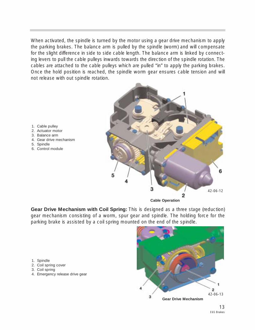
When activated, the spindle is turned by the motor using a gear drive mechanism to applythe parking brakes. The balance arm is pulled by the spindle (worm) and will compensatefor the slight difference in side to side cable length. The balance arm is linked by connect-ing levers to pull the cable pulleys inwards towards the direction of the spindle rotation. Thecables are attached to the cable pulleys which are pulled “in” to apply the parking brakes.Once the hold position is reached, the spindle worm gear ensures cable tension and willnot release with out spindle rotation.
Gear Drive Mechanism with Coil Spring: This is designed as a three stage (reduction)gear mechanism consisting of a worm, spur gear and spindle. The holding force for theparking brake is assisted by a coil spring mounted on the end of the spindle.
13E65 Brakes
42-06-12
42-06-13
Cable Operation
1. Cable pulley2. Actuator motor3. Balance arm4. Gear drive mechanism5. Spindle6. Control module
Gear Drive Mechanism
1. Spindle2. Coil spring cover3. Coil spring4. Emergency release drive gear
When the brake is released, the spindle is turned by the motor and gear drive mechanismin the opposite direction. The balance arm, connecting levers and cable pulleys are pushedoutwards by the spindle (worm). The cables are also pushed “out” to release the parkingbrakes. To assist in the release, return springs are installed in the parking brake assembliesinside the brake discs.
NNoottee:: With the manual emergency release, the spindle can be turned through the gear drivemechanism with the tools found in the vehicle tool kit to release the parking brake.
Workshop Hints
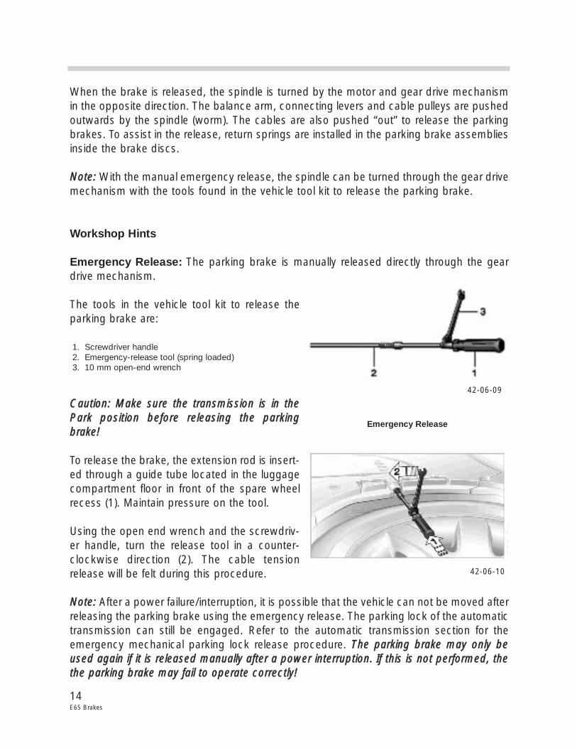
Emergency Release: The parking brake is manually released directly through the geardrive mechanism.
The tools in the vehicle tool kit to release theparking brake are:
CCaauuttiioonn:: MMaakkee ssuurree tthhee ttrraannssmmiissssiioonn iiss iinn tthheePPaarrkk ppoossiittiioonn bbeeffoorree rreelleeaassiinngg tthhee ppaarrkkiinnggbbrraakkee!!
To release the brake, the extension rod is insert-ed through a guide tube located in the luggagecompartment floor in front of the spare wheelrecess (1). Maintain pressure on the tool.
Using the open end wrench and the screwdriv-er handle, turn the release tool in a counter-clockwise direction (2). The cable tensionrelease will be felt during this procedure.
NNoottee:: After a power failure/interruption, it is possible that the vehicle can not be moved afterreleasing the parking brake using the emergency release. The parking lock of the automatictransmission can still be engaged. Refer to the automatic transmission section for theemergency mechanical parking lock release procedure. TThhee ppaarrkkiinngg bbrraakkee mmaayy oonnllyy bbeeuusseedd aaggaaiinn iiff iitt iiss rreelleeaasseedd mmaannuuaallllyy aafftteerr aa ppoowweerr iinntteerrrruuppttiioonn.. IIff tthhiiss iiss nnoott ppeerrffoorrmmeedd,, tthheetthhee ppaarrkkiinngg bbrraakkee mmaayy ffaaiill ttoo ooppeerraattee ccoorrrreeccttllyy!!
14E65 Brakes
Emergency Release
1. Screwdriver handle2. Emergency-release tool (spring loaded)3. 10 mm open-end wrench
42-06-09
42-06-10
Resuming Operation after Emergency Release: When the voltage supply has beenrestored after the emergency release, the parking brake ppuusshh bbuuttttoonn mmuusstt bbee pprreesssseedd 33ttiimmeess aatt iinntteerrvvaallss ooff aapppprrooxx.. 55 sseeccoonnddss ttoo iinniittiiaalliizzee tthhee ssyysstteemm.. This procedure is alsodescribed in the Owner's Handbook and Towing Instructions for BMW 7 Series.
• 11sstt pprreessss - The control module attempts to release the brake. Since the brake has been released mechanically by the emergency release, the motor cannot run back and blocks. The control module recognizes a disengaged setting.
• 22nndd pprreessss - The motor will move forward applying the parking brake. The control mod-ule detects an engaged setting. The “P” indicator light illuminates in red.
• 33rrdd pprreessss - The motor will run backward releasing the parking brake and the “P” indica-tor light goes out. The parking brake is ready for operation.
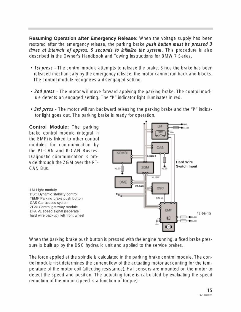
Control Module: The parkingbrake control module (integral inthe EMF) is linked to other controlmodules for communication bythe PT-CAN and K-CAN Busses.Diagnostic communication is pro-vide through the ZGM over the PT-CAN Bus.
When the parking brake push button is pressed with the engine running, a fixed brake pres-sure is built up by the DSC hydraulic unit and applied to the service brakes.
The force applied at the spindle is calculated in the parking brake control module. The con-trol module first determines the current flow of the actuating motor accounting for the tem-perature of the motor coil (affecting resistance). Hall sensors are mounted on the motor todetect the speed and position. The actuating force is calculated by evaluating the speedreduction of the motor (speed is a function of torque).
15E65 Brakes
42-06-15
LM Light moduleDSC Dynamic stability controlTEMF Parking brake push buttonCAS Car access systemZGM Central gateway moduleDFA VL speed signal (seperate hard wire backup), left front wheel
Hard WireSwitch Input
Principle of Operation
Parking Brake Control
Two separate controls are provided to operate the parking brake functions.
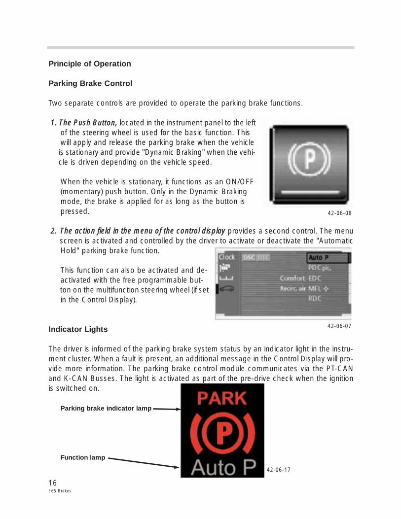
11.. TThhee PPuusshh BBuuttttoonn,, located in the instrument panel to the left of the steering wheel is used for the basic function. This will apply and release the parking brake when the vehicle is stationary and provide "Dynamic Braking" when the vehi-cle is driven depending on the vehicle speed.
When the vehicle is stationary, it functions as an ON/OFF (momentary) push button. Only in the Dynamic Braking mode, the brake is applied for as long as the button is pressed.
22.. TThhee aaccttiioonn ffiieelldd iinn tthhee mmeennuu ooff tthhee ccoonnttrrooll ddiissppllaayy provides a second control. The menu screen is activated and controlled by the driver to activate or deactivate the "Automatic Hold" parking brake function.
This function can also be activated and de- activated with the free programmable but-ton on the multifunction steering wheel (if set in the Control Display).
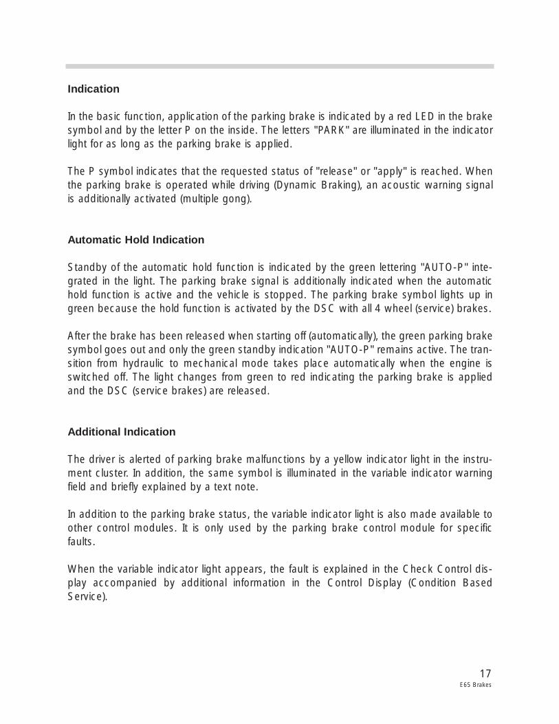
Indicator Lights
The driver is informed of the parking brake system status by an indicator light in the instru-ment cluster. When a fault is present, an additional message in the Control Display will pro-vide more information. The parking brake control module communicates via the PT-CANand K-CAN Busses. The light is activated as part of the pre-drive check when the ignitionis switched on.
Parking brake indicator lamp
Function lamp
16E65 Brakes
42-06-08
42-06-17
42-06-07
Indication
In the basic function, application of the parking brake is indicated by a red LED in the brakesymbol and by the letter P on the inside. The letters "PARK" are illuminated in the indicatorlight for as long as the parking brake is applied.
The P symbol indicates that the requested status of "release" or "apply" is reached. Whenthe parking brake is operated while driving (Dynamic Braking), an acoustic warning signalis additionally activated (multiple gong).
Automatic Hold Indication
Standby of the automatic hold function is indicated by the green lettering "AUTO-P" inte-grated in the light. The parking brake signal is additionally indicated when the automatichold function is active and the vehicle is stopped. The parking brake symbol lights up ingreen because the hold function is activated by the DSC with all 4 wheel (service) brakes.
After the brake has been released when starting off (automatically), the green parking brakesymbol goes out and only the green standby indication "AUTO-P" remains active. The tran-sition from hydraulic to mechanical mode takes place automatically when the engine isswitched off. The light changes from green to red indicating the parking brake is appliedand the DSC (service brakes) are released.
Additional Indication
The driver is alerted of parking brake malfunctions by a yellow indicator light in the instru-ment cluster. In addition, the same symbol is illuminated in the variable indicator warningfield and briefly explained by a text note.
In addition to the parking brake status, the variable indicator light is also made available toother control modules. It is only used by the parking brake control module for specificfaults.
When the variable indicator light appears, the fault is explained in the Check Control dis-play accompanied by additional information in the Control Display (Condition BasedService).
17E65 Brakes
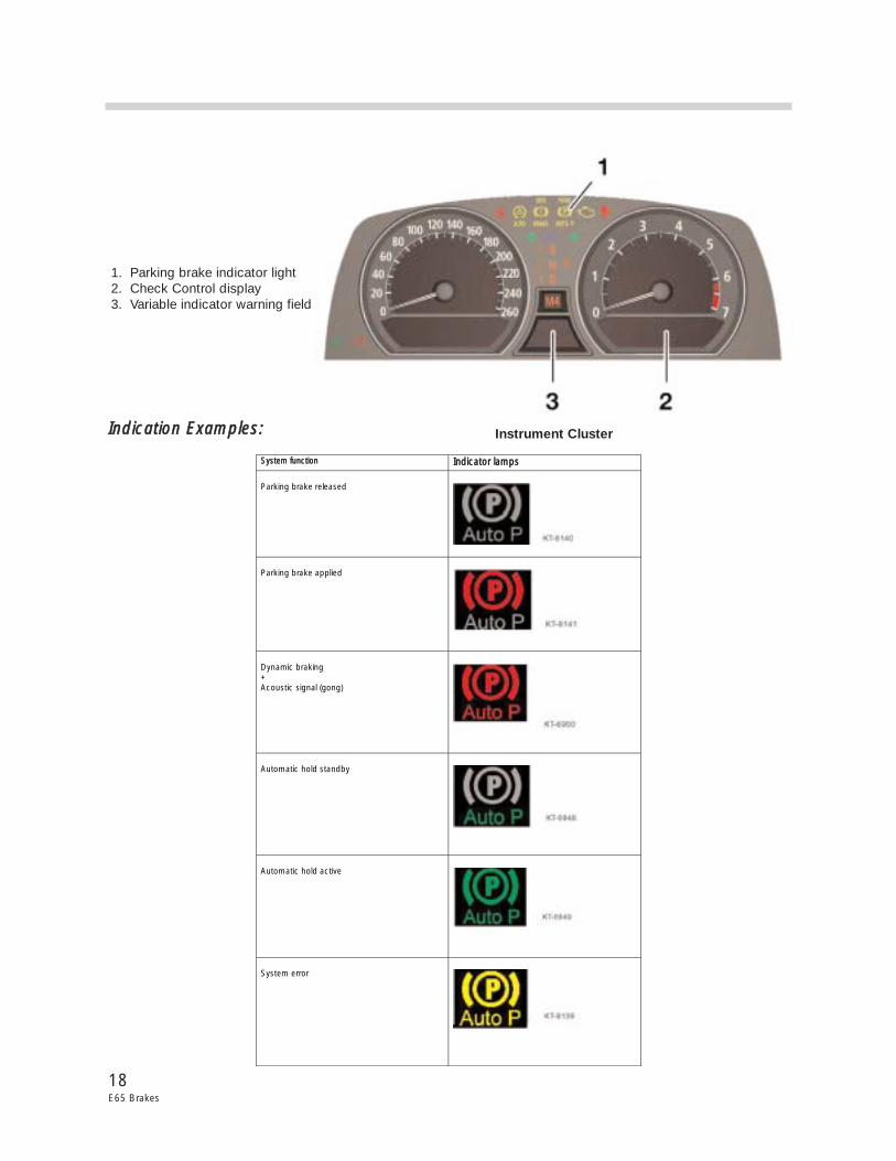
IInnddiiccaattiioonn EExxaammpplleess::
18E65 Brakes
SSyysstteemm ffuunnccttiioonn IInnddiiccaattoorr llaammppss Parking brake released
�
�
Parking brake applied
�
�
Dynamic braking + Acoustic signal (gong)
�
�
Automatic hold standby
�
�
Automatic hold active
�
�
System error
�
�
Instrument Cluster
1. Parking brake indicator light2. Check Control display3. Variable indicator warning field
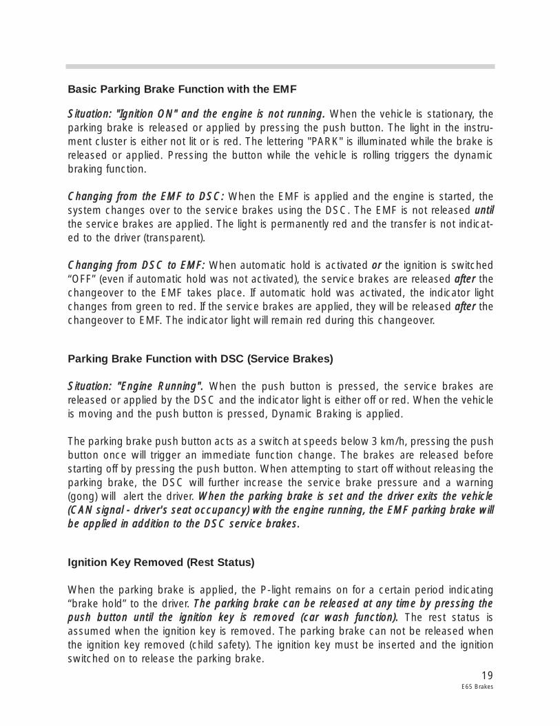
Basic Parking Brake Function with the EMF
SSiittuuaattiioonn:: ""IIggnniittiioonn OONN"" aanndd tthhee eennggiinnee iiss nnoott rruunnnniinngg.. When the vehicle is stationary, theparking brake is released or applied by pressing the push button. The light in the instru-ment cluster is either not lit or is red. The lettering "PARK" is illuminated while the brake isreleased or applied. Pressing the button while the vehicle is rolling triggers the dynamicbraking function.
CChhaannggiinngg ffrroomm tthhee EEMMFF ttoo DDSSCC:: When the EMF is applied and the engine is started, thesystem changes over to the service brakes using the DSC. The EMF is not released uunnttiillthe service brakes are applied. The light is permanently red and the transfer is not indicat-ed to the driver (transparent).
CChhaannggiinngg ffrroomm DDSSCC ttoo EEMMFF:: When automatic hold is activated oorr the ignition is switched“OFF” (even if automatic hold was not activated), the service brakes are released aafftteerr thechangeover to the EMF takes place. If automatic hold was activated, the indicator lightchanges from green to red. If the service brakes are applied, they will be released aafftteerr thechangeover to EMF. The indicator light will remain red during this changeover.
Parking Brake Function with DSC (Service Brakes)
SSiittuuaattiioonn:: ""EEnnggiinnee RRuunnnniinngg"".. When the push button is pressed, the service brakes arereleased or applied by the DSC and the indicator light is either off or red. When the vehicleis moving and the push button is pressed, Dynamic Braking is applied.
The parking brake push button acts as a switch at speeds below 3 km/h, pressing the pushbutton once will trigger an immediate function change. The brakes are released beforestarting off by pressing the push button. When attempting to start off without releasing theparking brake, the DSC will further increase the service brake pressure and a warning(gong) will alert the driver. WWhheenn tthhee ppaarrkkiinngg bbrraakkee iiss sseett aanndd tthhee ddrriivveerr eexxiittss tthhee vveehhiiccllee((CCAANN ssiiggnnaall -- ddrriivveerr''ss sseeaatt ooccccuuppaannccyy)) wwiitthh tthhee eennggiinnee rruunnnniinngg,, tthhee EEMMFF ppaarrkkiinngg bbrraakkee wwiillllbbee aapppplliieedd iinn aaddddiittiioonn ttoo tthhee DDSSCC sseerrvviiccee bbrraakkeess..
Ignition Key Removed (Rest Status)
When the parking brake is applied, the P-light remains on for a certain period indicating“brake hold” to the driver. TThhee ppaarrkkiinngg bbrraakkee ccaann bbee rreelleeaasseedd aatt aannyy ttiimmee bbyy pprreessssiinngg tthheeppuusshh bbuuttttoonn uunnttiill tthhee iiggnniittiioonn kkeeyy iiss rreemmoovveedd ((ccaarr wwaasshh ffuunnccttiioonn)).. The rest status isassumed when the ignition key is removed. The parking brake can not be released whenthe ignition key removed (child safety). The ignition key must be inserted and the ignitionswitched on to release the parking brake.
19E65 Brakes
Automatic Hold Function
The Automatic Hold function is activated by selecting “Auto P” in the Control Display (orMFL free programmable button) oonnllyy wwhheenn tthhee eennggiinnee iiss rruunnnniinngg aanndd tthhee hhoooodd iiss cclloosseedd (orthe hood contact switch is in the service position). It then remains operational until the nexttime the engine is switched off. When selected, the vehicle is automatically held by the ser-vice brakes each time it comes to a stop. This also applies when the Automatic Hold func-tion is requested and the vehicle is stationary.
When the vehicle is stationary, the brake pressure that the driver applies from the brakepedal is "locked in". When the vehicle comes to a stop without operating the brake pedal(roll to a stop), hydraulic pressure is built up by the DSC pump. Increased pressure will beautomatically supplied if the vehicle begins to roll (detected by the wheel speed sensors).
When the automatic transmission is engaged in a drive gear, the brakes will be automati-cally released by pressing on the accelerator pedal. The next time the vehicle stops it willbe automatically held by the service brakes. The standby status of the automatic mode isindicated by the green lettering "Auto-P". When the vehicle is stationary, the parking brakesymbol is additionally illuminated in green.
The Automatic Hold function is deactivated by selecting “OFF” in the Control Display (orMFL free programmable button). This will not change the current parking brake status. Thismeans when the vehicle is stationary, it remains held hydraulically after selecting "Auto-POFF". The parking brake indicator light will change from green to red and the "Auto-P" indi-cator will go out.
The Automatic Hold function is always aborted when the push button is pressed and mustbe reactivated by selecting “ON” in the Control Display (or MFL button). When the engineis switched “OFF” in the Automatic Hold function, the EMF will apply the parking brake.
The parking brake can be released at any time by pressing the push button until the igni-tion key is removed (car wash function). The parking brake will apply after the ignition keyhas been removed.
Automatic Hold Safety Control
Release of the Automatic Hold function by pressing the accelerator pedal is based on twosafety functions.
SSiittuuaattiioonn:: HHoooodd ooppeenn.. Automatic release of the service brakes when the accelerator pedalis pressed is inhibited when the hood is open (CAN signal - hood contact switch) while theengine is running.
20E65 Brakes
In this situation, the parking brake can only be released by pressing the push button(Automatic Hold deactivation). When the hood is closed, the Automatic Hold must beselected again by the driver. This situation also applies when the luggage compartment(trunk) lid is open and Reverse is engaged.
SSiittuuaattiioonn:: TThhee ddrriivveerr eexxiittss tthhee vveehhiiccllee.. When the driver exits the vehicle (CAN signal - dri-ver's seat occupancy) with the engine running, the automatic release of the service brakesby pressing the accelerator pedal is inhibited. The EMF parking brake will also be appliedand the transmission will automatically shift to the P-position.
When the driver re-enters the vehicle (CAN signal - driver's seat occupancy), the brakepedal must be pressed and a transmission drive gear must be engaged to drive off. Thebrake light switch signal requests the EMF to release the parking brake. The AutomaticHold function must be selected again by the driver.
Dynamic Braking
Two separate controls are required by law for brake operation, the brake pedal and hand-brake lever were previously used. In the E65, the footbrake and the push button in thedashboard fulfills the requirements.
When the vehicle is moving and the engine is “OFF”, the EMF parking brake is applied whenpressure is maintained on the push button at speeds below 3 km/h. During this situation,the parking brake is applied for 0.8 seconds. For the next 2 seconds there is an increasein the braking power and the rate of deceleration is maintained as long as the push buttonis pressed.
The Dynamic Braking function is active while the vehicle is rolling at speeds above 3 km/h(when the ignition is in position KLR or KL15) when pressure is maintained on the push but-ton. This maintains vehicle stability by preventing overbraking of the rear axle using DSChydraulic pressure build-up application to the service brakes. The required brake pressureis made available as fast as possible by the DSC.
Since braking takes place hydraulically on all four wheels, higher deceleration rates are pos-sible with minimum operating force as compared to the EMF parking brakes. This con-trolled braking contributes to increased vehicle safety. FFoorr ssaaffeettyy rreeaassoonnss,, ttrraaffffiicc iiss wwaarrnneeddwwhheenn DDyynnaammiicc BBrraakkiinngg iiss aaccttiivvee bbyy tthhee bbrraakkee lliigghhttss..
To avoid incorrect operation, the "Release Parking Brake" display and gong draw the dri-ver's attention to Dynamic Brake operation. TThhiiss ffuunnccttiioonn sshhoouulldd oonnllyy bbee uusseedd iinn eexxcceepp--ttiioonnaall cciirrccuummssttaanncceess..
21E65 Brakes
22E65 Brakes
When Dynamic Braking is activated until the vehicle comes to a stop, the vehicle will remainheld by the service brakes and the red P-indicator light remains on. If the brake pedal ispressed during this operation, the DSC interprets this as a higher priority and will overridethe parking brake function.
EExxiittiinngg tthhee ddyynnaammiicc eemmeerrggeennccyy bbrraakkiinngg ffuunnccttiioonn:: After emergency braking the vehicle to astop, the vehicle will remain held by the service brakes even after releasing the parkingbrake push button. The service brakes will not be released until the push button is pressedagain.
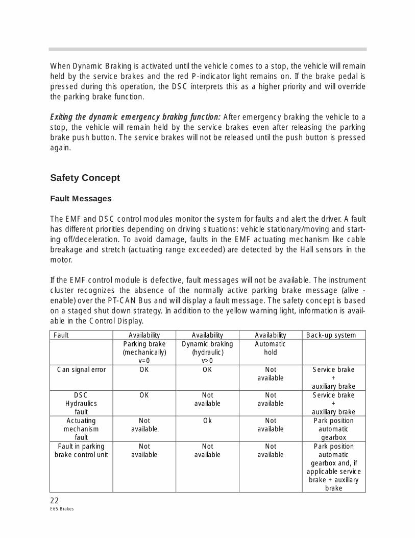
Safety Concept
Fault Messages
The EMF and DSC control modules monitor the system for faults and alert the driver. A faulthas different priorities depending on driving situations: vehicle stationary/moving and start-ing off/deceleration. To avoid damage, faults in the EMF actuating mechanism like cablebreakage and stretch (actuating range exceeded) are detected by the Hall sensors in themotor.
If the EMF control module is defective, fault messages will not be available. The instrumentcluster recognizes the absence of the normally active parking brake message (alive -enable) over the PT-CAN Bus and will display a fault message. The safety concept is basedon a staged shut down strategy. In addition to the yellow warning light, information is avail-able in the Control Display.
Fault Availability Availability Availability Back-up system Parking brake
(mechanically) v=0
Dynamic braking (hydraulic)
v>0
Automatic hold
Can signal error OK OK Not available
Service brake +
auxiliary brake DSC
Hydraulics fault
OK Not available
Not available
Service brake +
auxiliary brake Actuating
mechanism fault
Not available
Ok Not available
Park position automatic gearbox
Fault in parking brake control unit
Not available
Not available
Not available
Park position automatic
gearbox and, if applicable service brake + auxiliary
brake
23E65 Brakes
General Parking Brake Fault Concept
FFaauulltt ddiivviissiioonn bbeettwweeeenn DDSSCC aanndd EEMMFF ccoonnttrrooll mmoodduullee:: DSC faults that only affect the park-ing brake will result in a shut down of the hydraulic function (Dynamic Braking not possi-ble). These are typically faults that result in a shut down of the ABS functions and ManualEmergency Mode will be assumed by the EMF. If the fault is only a CAN Bus fault, DynamicBraking will be possible.
Shut Down Stage of "Manual Emergency Mode"
This will only apply when the EMF actuating unit is not in operation and is implemented forone of the following DSC faults:
• DSC control module defect• Electrical defect (example: wiring harness)• Sensor fault (brake pressure sensor, wheel speed sensors)• EMF actuator fault, DSC hydraulic unit• CAN communication fault
Shut Down Stage "Only Dynamic Braking Available"
This stage will provide Dynamic Braking by the DSC hydraulic service brakes in the eventof an EMF actuating failure.
• Fault in the actuating motor Hall sensors• Actuating motor fault• Fault in control electronics• Fault in actuating mechanism (mechanical)• Electrical faults
Shut Down Stage "Total Shut Down"
• Parking brake control module failure • Push button fault• Electrical faults including voltage supply
All fault codes are stored in the EMF control module and is also informed of the DSC con-trol module fault status.
24E65 Brakes
Fault Regeneration
If a fault is detected, the system remains in the current stage until the ignition is switched“OFF”. A shut down situation will not be deactivated until the faulty component is operat-ing correctly. If the fault is not present during the next restart, the shut down stage is can-celled to resume normal operation. Component tests are carried out continually, even dur-ing the shut down situation.
The fault information remains stored in the fault code memory. If correct function of thecomponent cannot be determined after a fault has occurred, the parking brake will remainin the safe, shut down state until the next workshop visit with the exception of: CAN time-out error, overvoltage and temperature protection. After properly repaired, the fault can bedeleted with the DISplus.
Regeneration of CAN Faults
CAN timeout faults can be regenerated. The shut down stage is cancelled if the signal isreceived correctly for a certain period of time.
Monitoring and Fault Detection
EElleeccttrriiccaall ffaauullttss mmoonniittoorriinngg:: The wiring to the EMF control module including the actuatormotor are monitored for breaks or shorts to B+ and ground.
HHyyddrraauulliicc iinntteerrffaaccee mmoonniittoorriinngg:: The DCS checks the plausibility of the deceleration requestby the parking brake during Dynamic Braking and the hydraulic Hold Function. If therequest and feedback do not agree within a defined time (5 seconds), the correspondingshut down stage is assumed and a fault code will be stored.
IInnppuutt ssiiggnnaallss mmoonniittoorriinngg:: In the event of a faulty input signal, the entire system is shut downwith a Check Control error message and a stored fault code.
PPaarrkkiinngg bbrraakkee ppuusshh bbuuttttoonn mmoonniittoorriinngg:: The push button signals are continually monitored(hardwired to the EMF control module). In the event of a push button plausibility fault, theentire parking brake system is shut down and the "Parking Brake Push Button Defective"fault code is stored. The DSC control module also checks the plausibility of the parkingbrake push button signals that are transmitted via the CAN Bus (from the EMF control mod-ule). If faulty, the "Parking Brake Push Button Signals via CAN Implausible" fault code isstored and partial shut down is carried out (Dynamic Braking is not possible).
25E65 Brakes
SSppeeeedd ssiiggnnaallss mmoonniittoorriinngg:: Total shut down of the parking brake system will occur with theloss of all 3 speed inputs.
• The direct digital wheel speed signal (separate hard wire backup, front left) is contin-ually checked for the plausibility of the signal edge change.
• The plausibility of the reference speed signal from the DSC over the PT-CAN Bus and the direct digital wheel speed signal is continually and mutually checked.
• The reference speed signal from the DSC is compared with the automatic transmission output speed.
Fault codes:
• Direct wheel speed signal implausible or faulted
• DSC speeds implausible or no message
• EGS automatic transmission output speed implausible or no message
HHaallll sseennssoorrss mmoonniittoorriinngg:: The plausibility of the actuating motor Hall sensors is continuallychecked. When there are deviations that are out of tolerance, partial shut down (onlyDynamic Braking available) is implemented and the "Parking Brake Actuating UnitDefective, Plausibility of Hall Sensors" fault code will be set.
In addition, the plausibility of the position is checked during the actuating motor operation.When the Hall sensor signal is not received, the parking brake system is shut down and afault code will be set.
EEMMFF aaccttuuaattiinngg uunniitt mmoonniittoorriinngg:: After the ignition is switched on and a fault is present, it willbe detected before a required parking brake function is active.
EMF Self Diagnostics
The self diagnostic functions are divided into several modes. These modes are executed inpriority for diagnosis. When the vehicle is stationary and self diagnosis is being executed,the parking brake function is fully operational. Fewer diagnostic modes are allowed whilethe vehicle is moving. A self diagnostic mode that will restrict or completely deactivate theparking brake function is executed only when the vehicle is stationary.
26E65 Brakes
Certain faults in CAN communication will cause the manual emergency mode and theAutomatic Hold will not function. The "manual level" is operational and the parking brakewill still be applied and released by the EMF or DSC when the push button is pressed withthe vehicle stationary. Dynamic Braking also remains available. The loss of the AutomaticHold function is indicated only with the variable parking brake indicator lamp.
Workshop Hints
Please familiarize yourself with the statements below regarding new procedures when mak-ing repairs to the Electro-mechanical Parking Brake. Consult the Repair Information in TISfor additional information on the following procedures:
The parking brake shoes are adjusted the same way as current BMW models by turningthe adjuster with a screwdriver through the wheel bolt hole of the wheel hub.
PPaarrkkiinngg bbrraakkee ccaabbllee rreemmoovvaall:: To remove the parking brake cable assemblies, the EMF topcover must be removed and the end stop plate must be raised with a screwdriver. Usingthe brake release tool (found in the vehicle tool kit), release the parking brake completelyso that the balance arm is turned back to the stop. This will allow the pulleys to rotate farenough so that the cable crimp can be disengaged from the recess in the pulley.
PPaarrkkiinngg bbrraakkee iinniittiiaalliizzaattiioonn:: The parking brake must be initialized with the DISplus afterreplacing the brake shoes. The brake cable “free play” is learned by the EMF control mod-ule from the Hall sensors in the actuating motor.
PPaarrkkiinngg bbrraakkee lliinniinngg sseeaattiinngg:: When the parking brake shoes are replaced, the new brakelinings must be seated (bedded down) to achieve adequate holding power. A "SpecialBedding Down Routine" is integrated in the parking brake software and can be accessedwith the DISplus found under SSeerrvviiccee FFuunnccttiioonnss -- CChhaassssiiss -- PPaarrkkiinngg BBrraakkee -- WWoorrkksshhooppBBrraakkiinngg--iinn..
The parking brake indicator light in the instrument cluster will flash red (at a low frequency)to signal the standby status of the brake bedding down program. After activating the pro-gram, the ignition must not be switched off and the bedding down procedure must be car-ried out within 30 minutes.
If more than 30 minutes have lapsed, the parking brake button is pushed, or the ignition isturned off before the procedure is carried out, the brake bedding down program will be ter-minated. The system will resume the normal parking brake function.
27E65 Brakes
The brake linings are seated by the EMF applying a reduced holding force. The brakingforce at the spindle during this procedure is 20% of the maximum actuating force.
The procedure is activated when the vehicle is stationary (for example: stopped at a trafficlight). The brake shoes “scrub” when the vehicle starts off. The EMF releases the parkingbrakes when a speed of 15 km/h is reached or 30 seconds after the start of the seatingprocedure.
For safety reasons, the seating procedure is immediately terminated when any DSC func-tion is required. The seating procedure is also terminated when the push button is pressedor the ignition is turned off.
TTrraavveell mmoonniittoorriinngg:: Normal parking brake lining wear increases the actuating travel over theservice life. Based on the reference point (stop in the EMF unit), the Hall sensors in the actu-ating motor allows the EMF control module to measure the travel range.
When the defined travel limit is exceeded, information is provided to the driver and a faultis stored in the EMF control module. This can also be checked using the DISplus foundunder SSeerrvviiccee FFuunnccttiioonnss -- CChhaassssiiss -- PPaarrkkiinngg BBrraakkee -- PPoossiittiioonn TTrraavveell CChheecckk..
BBrraakkee tteessttiinngg oonn aa rroolllleerr ddyynnaammoommeetteerr:: The E65 parking brake operation can be tested ona brake roller dynamometer. The parking brake test can be conducted with the engine run-ning by pressing the parking brake push button. With the engine turned off, the parkingbrake test can activated by pressing the parking brake push button. The actuating unit willquickly apply and lock the parking brake.
AAsssseemmbbllyy MMooddee:: Replacement EMFs are shipped in “assembly mode” to surpress activa-tion until the brake cables and EMF are completely assembled and installed in the vehicle.This prevents unintentional operation of the EMF by the parking brake push button and canalso be activated (for safety reasons) on an existing EMF in the vehicle when work is beingperformed.
BBeeffoorree iinniittiiaall ooppeerraattiioonn,, tthhee aasssseemmbbllyy mmooddee mmuusstt bbee ddeeaaccttiivvaatteedd bbyy uussiinngg tthhee DDIISSpplluussffoouunndd uunnddeerr:: SSeerrvviiccee FFuunnccttiioonnss -- CChhaassssiiss -- PPaarrkkiinngg BBrraakkee -- AAsssseemmbbllyy MMooddee..
When installing the EMF, make sure that the seal to the body and the seals for the parkingbrake cables are correctly installed.
CCooddiinngg ddaattaa:: The coding data for the parking brake system is stored in the EMF controlmodule (EEPROM) and the DSC control module (EEPROM). The coding data is entered bythe DISplus when a control module is replaced.
28E65 Brakes
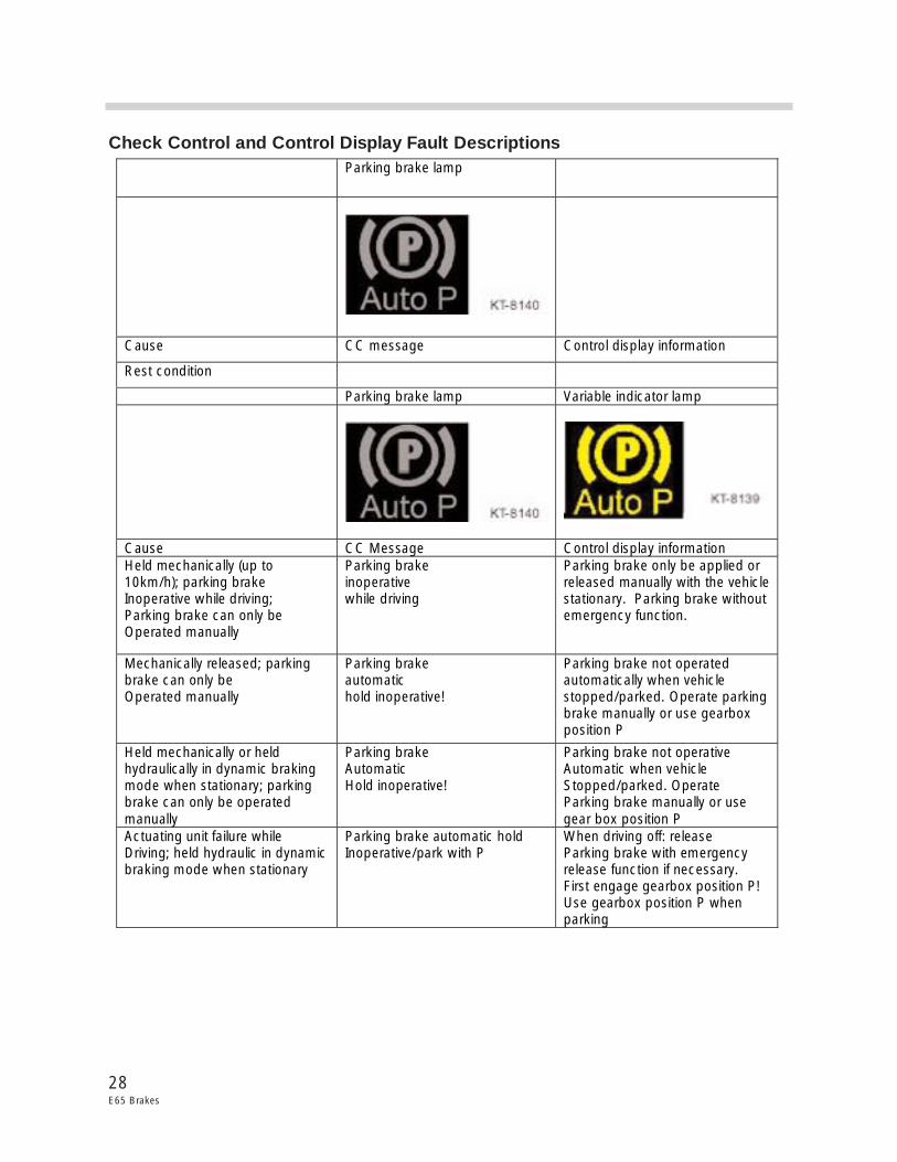
Check Control and Control Display Fault Descriptions Parking brake lamp
Cause CC message Control display information
Rest condition
Parking brake lamp Variable indicator lamp
Cause CC Message Control display information Held mechanically (up to 10km/h); parking brake Inoperative while driving; Parking brake can only be Operated manually
Parking brake inoperative while driving
Parking brake only be applied or released manually with the vehicle stationary. Parking brake without emergency function.
Mechanically released; parking brake can only be Operated manually
Parking brake automatic hold inoperative!
Parking brake not operated automatically when vehicle stopped/parked. Operate parking brake manually or use gearbox position P
Held mechanically or held hydraulically in dynamic braking mode when stationary; parking brake can only be operated manually
Parking brake Automatic Hold inoperative!
Parking brake not operative Automatic when vehicle Stopped/parked. Operate Parking brake manually or use gear box position P
Actuating unit failure while Driving; held hydraulic in dynamic braking mode when stationary
Parking brake automatic hold Inoperative/park with P
When driving off: release Parking brake with emergency release function if necessary. First engage gearbox position P! Use gearbox position P when parking
29E65 Brakes
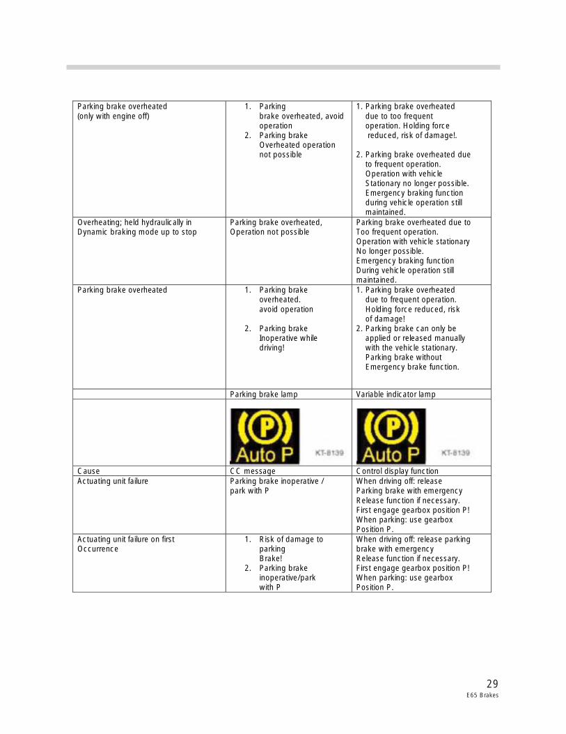
�
Parking brake overheated (only with engine off)
1. Parking brake overheated, avoid operation
2. Parking brake Overheated operation not possible
1. Parking brake overheated due to too frequent operation. Holding force reduced, risk of damage!. 2. Parking brake overheated due to frequent operation. Operation with vehicle Stationary no longer possible. Emergency braking function during vehicle operation still maintained.
Overheating; held hydraulically in Dynamic braking mode up to stop
Parking brake overheated, Operation not possible
Parking brake overheated due to Too frequent operation. Operation with vehicle stationary No longer possible. Emergency braking function During vehicle operation still maintained.
Parking brake overheated 1. Parking brake overheated. avoid operation
2. Parking brake Inoperative while driving!
1. Parking brake overheated due to frequent operation. Holding force reduced, risk of damage! 2. Parking brake can only be applied or released manually with the vehicle stationary. Parking brake without Emergency brake function.
Parking brake lamp Variable indicator lamp
Cause CC message Control display function Actuating unit failure Parking brake inoperative /
park with P When driving off: release Parking brake with emergency Release function if necessary. First engage gearbox position P! When parking: use gearbox Position P.
Actuating unit failure on first Occurrence
1. Risk of damage to parking Brake!
2. Parking brake inoperative/park with P
When driving off: release parking brake with emergency Release function if necessary. First engage gearbox position P! When parking: use gearbox Position P.
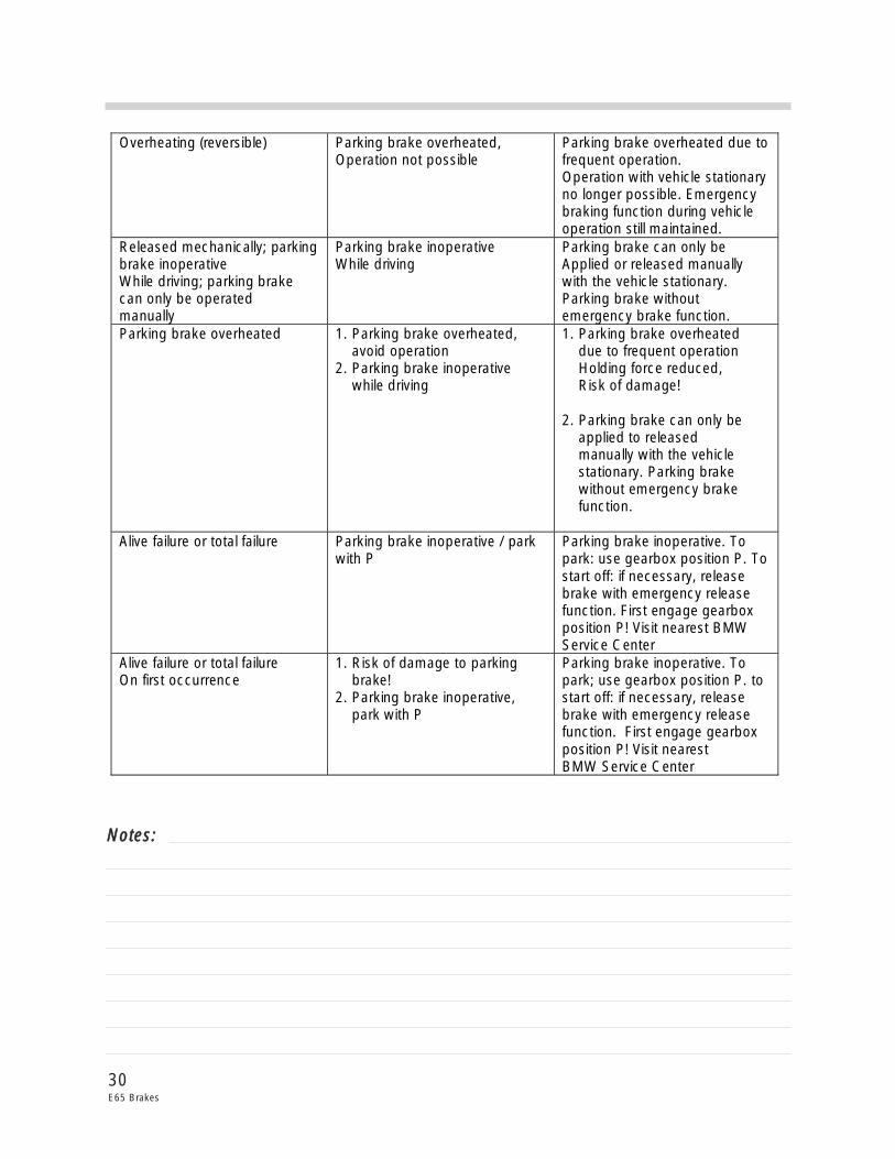
30E65 Brakes
Overheating (reversible) Parking brake overheated, Operation not possible
Parking brake overheated due to frequent operation. Operation with vehicle stationary no longer possible. Emergency braking function during vehicle operation still maintained.
Released mechanically; parking brake inoperative While driving; parking brake can only be operated manually
Parking brake inoperative While driving
Parking brake can only be Applied or released manually with the vehicle stationary. Parking brake without emergency brake function.
Parking brake overheated 1. Parking brake overheated, avoid operation 2. Parking brake inoperative while driving
1. Parking brake overheated due to frequent operation Holding force reduced, Risk of damage! 2. Parking brake can only be applied to released manually with the vehicle stationary. Parking brake without emergency brake function.
Alive failure or total failure Parking brake inoperative / park with P
Parking brake inoperative. To park: use gearbox position P. To start off: if necessary, release brake with emergency release function. First engage gearbox position P! Visit nearest BMW Service Center
Alive failure or total failure On first occurrence
1. Risk of damage to parking brake! 2. Parking brake inoperative, park with P
Parking brake inoperative. To park; use gearbox position P. to start off: if necessary, release brake with emergency release function. First engage gearbox position P! Visit nearest BMW Service Center
NNootteess::
31E65 Brakes
Parking brake lamp Variable indicator Lamp
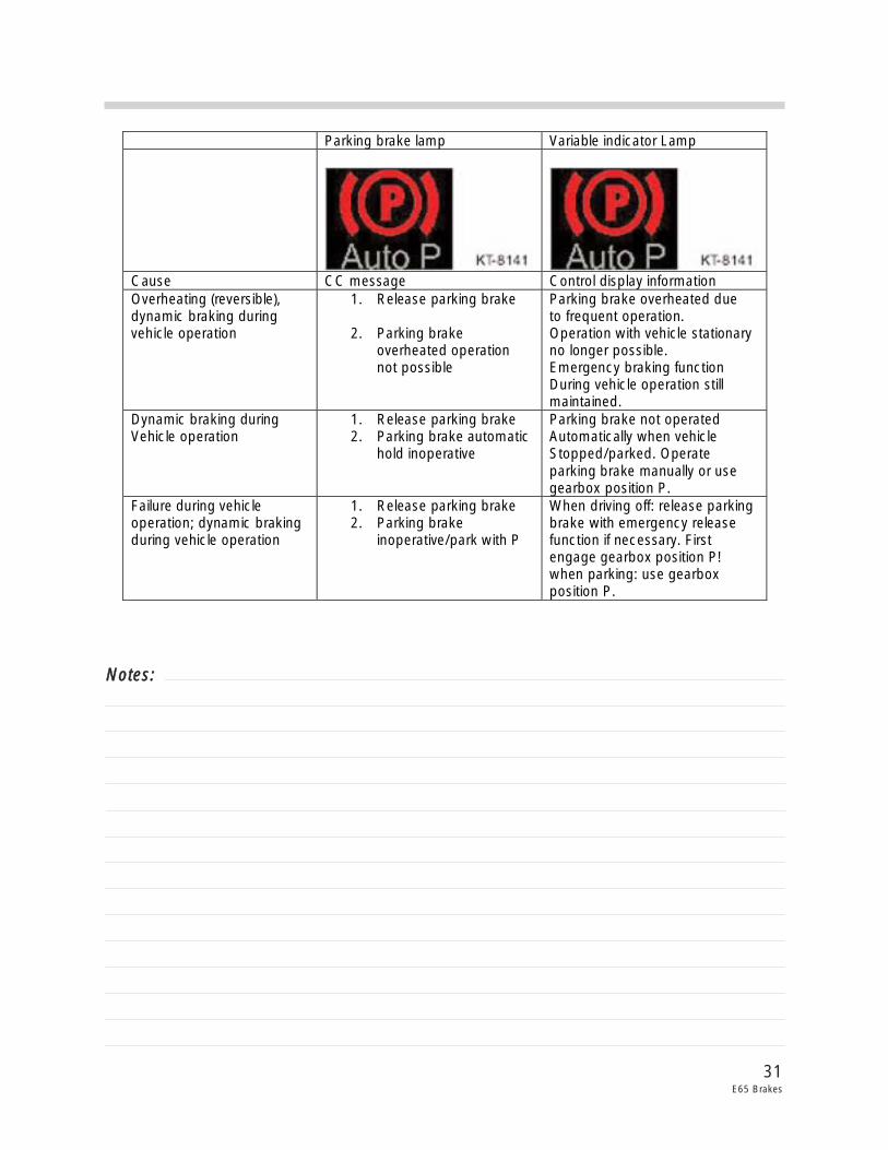
Cause CC message Control display information Overheating (reversible), dynamic braking during vehicle operation
1. Release parking brake 2. Parking brake
overheated operation not possible
Parking brake overheated due to frequent operation. Operation with vehicle stationary no longer possible. Emergency braking function During vehicle operation still maintained.
Dynamic braking during Vehicle operation
1. Release parking brake 2. Parking brake automatic
hold inoperative
Parking brake not operated Automatically when vehicle Stopped/parked. Operate parking brake manually or use gearbox position P.
Failure during vehicle operation; dynamic braking during vehicle operation
1. Release parking brake 2. Parking brake
inoperative/park with P
When driving off: release parking brake with emergency release function if necessary. First engage gearbox position P! when parking: use gearbox position P.
NNootteess::
32E65 Brakes
Parking brake lamp Variable indicator lamp
Flashing
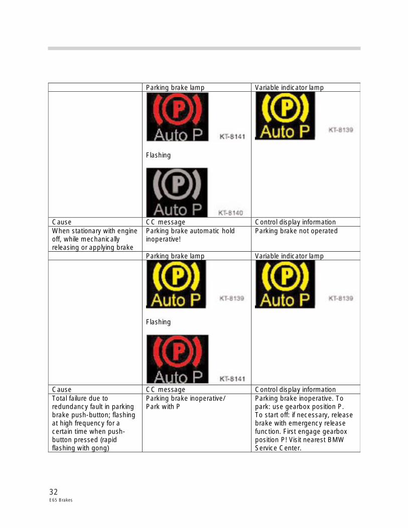
Cause CC message Control display information When stationary with engine off, while mechanically releasing or applying brake
Parking brake automatic hold inoperative!
Parking brake not operated
Parking brake lamp Variable indicator lamp
Flashing
Cause CC message Control display information Total failure due to redundancy fault in parking brake push-button; flashing at high frequency for a certain time when push-button pressed (rapid flashing with gong)
Parking brake inoperative/ Park with P
Parking brake inoperative. To park: use gearbox position P. To start off: if necessary, release brake with emergency release function. First engage gearbox position P! Visit nearest BMW Service Center.
�
33E65 Brakes
Parking brake lamp Variable indicator lamp
flashing
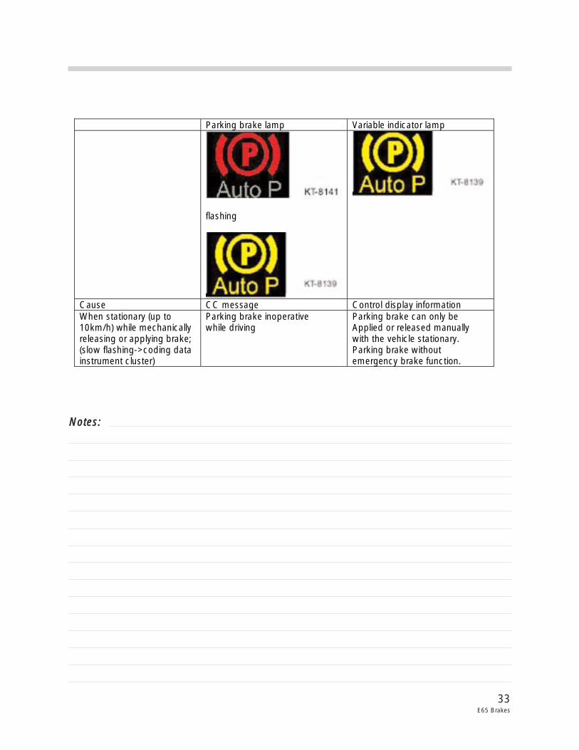
Cause CC message Control display information When stationary (up to 10km/h) while mechanically releasing or applying brake; (slow flashing->coding data instrument cluster)
Parking brake inoperative while driving
Parking brake can only be Applied or released manually with the vehicle stationary. Parking brake without emergency brake function.
NNootteess::