Table Chair
322
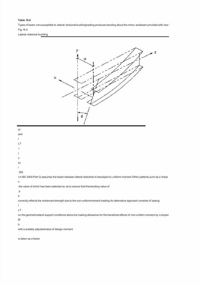
Table 16.6 Types of beam not susceptible to lateral–torsiona l bucklingloading produces bending about the minor axisbeam provided with clos Fig.16.4 Lateral–tor sional buckling The central feature in the above process is the determination of a measure of thebeam’s lateral–torsional buckling strength ( p b ) in terms of a parameter ( l LT ) whichrepresents those factors which control this strength.Modifications to the basicprocess permit the method to be used for une p b and l LT of BS 5950:Part 1 (and between s li / s yc and l LT ÷ ( s yc / 355 ) in BS 5400:Part 3) assumes the beam between lateral restraints to besubject to uniform moment.Other pattern s,such as a linear n ,the value of which has been selected so as to ensure that theresulting value of p b correctly reflects the enhanced strength due to the non-uniformmoment loading.An alternative approach consists of basing l LT on the geometricaland support conditions alone but making allowance for the beneficial effects of non-unifo rm moment by c ompari M b with a suitably adjustedvalue of design moment . is taken as a factor
-
Upload
jeve-militante -
Category
Documents
-
view
216 -
download
0
Transcript of Table Chair

7/29/2019 Table Chair
http://slidepdf.com/reader/full/table-chair 1/322
Table 16.6
Types of beam not susceptible to lateral–torsional bucklingloading produces bending about the minor axisbeam provided with clos
Fig.16.4
Lateral–torsional buckling
The central feature in the above process is the determination of a measure of thebeam’s lateral–torsional buckling strength (p
b
) in terms of a parameter (
l
LT
) whichrepresents those factors which control this strength.Modications to the basicprocess permit the method to be used for une
p
b
and
l
LT
of BS 5950:Part 1 (and between
s
li
/
s
yc
and
l
LT
÷
(
s
yc
/
355
) in BS 5400:Part 3) assumes the beam between lateral restraints to besubject to uniform moment.Other patterns,such as a linear
n
,the value of which has been selected so as to ensure that theresulting value of
p
bcorrectly reects the enhanced strength due to the non-uniformmoment loading.An alternative approach consists of basing
l
LT
on the geometricaland support conditions alone but making allowance for the benecial effects of non-uniform moment by compari
M
b
with a suitably adjustedvalue of design moment
.
is taken as a factor

7/29/2019 Table Chair
http://slidepdf.com/reader/full/table-chair 2/322

7/29/2019 Table Chair
http://slidepdf.com/reader/full/table-chair 3/322
;then aseparate check that the capacity of the beam cross-section
M
c
is at least equal to
M
max
must also be made.In cases where is taken asM
max
,then the bucklingcheck will be more severe than (or in the ease of a stocky beam for which
M
b
=
M
c
,identical to) the cross-section capacity check.Allowance for non-uniform moment loading on cantilevers is normally treatedsomew
M M M M M
444
Beams
an end moment such as horizontal wind load acting on a façade,should be regardedas an ordinary beam since it does not have th
M
E
.Values of
M
E
may conveniently be obtainedfrom summaries of research data.
6
For example,BS 5950:Part 1 permits
l
LT
to becalculated from
-16.3
As an example of the use of this approach Fig.16.6 shows how signicantly higherload-carrying capacities may be obtained for a c
16.3.7Fully restrained beams
The design of beams is considerably simplied if lateral–torsional buckling effectsdo not have to be considered explicitly – a situati
Mb
may be taken as itsmoment capacity
M
c
and,in the absence of any reductions in
M
c
due to local buck-
l p

7/29/2019 Table Chair
http://slidepdf.com/reader/full/table-chair 4/322
LTypE
#NAME?
( )
÷
( )
2
EpMM//
Basic design
445
Fig.16.5
Design modications using
m
-factor or
n
-factor methods
ling,high shear or torsion,it should be designed for its full in-plane bending strength.Certain of the conditions corresponding to the c
l
below which buckling will not affect
M
b
of Table 38 of BS 5950:Part 1,are sufciently high (
l
=
340,225 and 170 for
D/B
ratios of 2,3 and 4,and
p
y
=
275N/mm
2
) that only in very rare cases will lateral–torsional buckling be a design consideration.Situations in which the form of construction e
446
Beams
Fig.16.6Lateral–torsional buckling of a tip-loaded cantilever
that the restraints will effectively prevent movement at the braced cross-sections,thereby acting as if they were rigid supports.In pr
Basic design
447
Fig.16.7
Effect of type of cross-section on theoretical elastic critical moment

7/29/2019 Table Chair
http://slidepdf.com/reader/full/table-chair 5/322
16.4Lateral bracing
For design to BS 5950:Part 1,unless the engineer is prepared to supplement the coderules with some degree of working from rst
7,8
Where properly designed restraint systems areused the limits on
l
LTfor
M
b
=
M
c
(or more correctly
p
b
=
p
y
)are given in Table 16.7.For beams in plastically-designed structures it is vital that premature failure dueto plastic lateral–torsional
L
/
r
y
to ensure satisfactory behaviour;it is not necessarilycompatible with the elastic design rules of section 4 of the code since accepta
M
p
.The expression of clause 5.3.3 of BS 5950:Part 1,
-16.4
makes no allowance for either of two potentially benecial effects:(1)moment gradient(2)restraint against lateral deection provided
Lr fpx
mycy
£+
( ) ( )
[ ]
3813027536
2212
///448
Beams
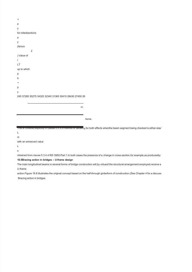
Table 16.7
Maximum values of
l
LT
forwhich
p
b

7/29/2019 Table Chair
http://slidepdf.com/reader/full/table-chair 6/322
=
p
y
for rolledsections
p
y
(N/mm2
) Value of
l
LT
up to which
p
b
=
p
y
245 37265 35275 34325 32340 31365 30415 28430 27450 26
of Brown,
9
the basis of which is the original work on plastic instability of Horne.
10
This is covered explicitly in clause 5.3.3.A method of allowing for both effects whenthe beam segment being checked is either elas
L
m
with an enhanced value
L
s
obtained from clause 5.3.4 of BS 5950:Part 1.In both cases the presence of a change in cross-section,for example,as producedby
16.5Bracing action in bridges – U-frame design
The main longitudinal beams in several forms of bridge construction will,by virtueof the structural arrangement employed,receive a
U-frame
action.Figure 16.8 illustrates the original concept based on the half-through girderform of construction.(See Chapter 4 for a discuss
Bracing action in bridges

7/29/2019 Table Chair
http://slidepdf.com/reader/full/table-chair 7/322
ly spaced or continuous lateral restraintclosed section
ual anged sections including tees,fabricated Is for which the section properties must be calculated,sections contain-ing slender pl
moment gradient reduc-ing from a maximum at one end or the parabolic distribution produced by a uniformload,are generally less
ng the resulting value of

7/29/2019 Table Chair
http://slidepdf.com/reader/full/table-chair 8/322
,whether on the slenderness axis of the
t

7/29/2019 Table Chair
http://slidepdf.com/reader/full/table-chair 9/322
at differently.For example,the set of effective length factors given in Table14 of Reference 1 includes allowances for the variation f
benet of non-uniform momentloading.For more complex arrangements that cannot reasonably be approximated by oneof the sta
ntilever with a tip load applied toits bottom ange,a case not specically covered by BS 5950:Part 1.
on which will occur if one or moreof the conditions of Table 16.6 are met.In these cases the beam’s buckling resistance moment

7/29/2019 Table Chair
http://slidepdf.com/reader/full/table-chair 10/322
ase where a beam may be regardedas ‘fully restrained’ are virtually self-evident but others require either judgement orcalculation.L
ployed automatically providessome degree of lateral restraint or for which a bracing system is to be used toenhance a beam’s str
ctice,bracing will possess a nitestiffness.A more fundamental discussion of the topic,which explains the exactnature of bracing sti

7/29/2019 Table Chair
http://slidepdf.com/reader/full/table-chair 11/322
rinciples,only restraints capable of acting as rigid supports are acceptable.Despite the absence of a specic stiffnessrequirement,
uckling does not impair the formation of the full plasticcollapse mechanism and the attainment of the plastic collapse load.Clause
lebehaviour can include the provision of adequate rotation capacity at momentsslightly below
by secondary structural membersattached to one ange as by the purlins on the top ange of a portal framerafter.The rst effect

7/29/2019 Table Chair
http://slidepdf.com/reader/full/table-chair 12/322
ic or partially plastic is given inAppendix G of BS 5950:Part 1;alternatively the effect of intermittent tension angerestraint alone m
the type of haunch usually used in portal frame construction,may be allowedfor.When the restraint is such that lateral deection of t
signicant measure of restraintagainst lateral–torsional buckling by a device commonly referred to as
ion of different bridge types.) Ina simply-supported span,the top (compression) anges of the main girders,althoughlaterally unbrac
7/29/2019 Table Chair
http://slidepdf.com/reader/full/table-chair 13/322
ate elements,members with properties that vary along their length,closed sections and ats.Various techniques for allowing for the
evere in terms of their effect on lateral stability;a givenbeam is likely to be able to withstand a larger peak moment before becomin

7/29/2019 Table Chair
http://slidepdf.com/reader/full/table-chair 14/322

7/29/2019 Table Chair
http://slidepdf.com/reader/full/table-chair 15/322
rom the arrangement usedas the basis for the s trength–slenderness relationship due to both the lateral supportconditions and the f
dard cases covered by correction factors,codes normally permit the directuse of the elastic critical moment

7/29/2019 Table Chair
http://slidepdf.com/reader/full/table-chair 16/322
ateral–torsional buckling cannot occur in beams loaded in their weaker princi-pal plane;under the action of increasing load they will
ngth require careful consideration.The fundamental require-ment of any form of restraint if it is to be capable of increasing the stre
fness and bracing strength,may be found in References 7 and8.Noticeably absent from the code clauses is a quantitative denition

7/29/2019 Table Chair
http://slidepdf.com/reader/full/table-chair 17/322
dherence to the strength requirement together with an awareness thatadequate stiffness is also necessary,avoiding obviously very
.3.3provides a basic limit on
ay be included in Equation (16.4) by adding the correction term

7/29/2019 Table Chair
http://slidepdf.com/reader/full/table-chair 18/322
y be allowed for by replacing
he beam’s compressionange is prevented at intervals,then Equation (16.4) applies between the pointsof effective lateral restraint.
d in the sense that no bracing may be attached directly to them,cannot buckle freely in the manner of Fig.16.4 since their lower a

7/29/2019 Table Chair
http://slidepdf.com/reader/full/table-chair 19/322
form of the appliedloading are also possible;some care is required in their use.The relationship between
lat-erally unstable.One means of allowing for this in design is to adjust the beam’s slen-derness by a factor

7/29/2019 Table Chair
http://slidepdf.com/reader/full/table-chair 20/322

7/29/2019 Table Chair
http://slidepdf.com/reader/full/table-chair 21/322
rm of the applied loading.When a cantilever is subdivided byone or more intermediate lateral restraints positioned between its root

7/29/2019 Table Chair
http://slidepdf.com/reader/full/table-chair 22/322
collapse simply by plasticaction and excessive in-plane deformation.Much the same is true for rectangularbox sections even when
gth of themain member is that it limits the buckling type deformations.An appreciation of exactly how the main member would buc
of ‘adequatestiffness’,although it has subsequently been suggested that a bracing system that is25 times stiffer than the braced b

7/29/2019 Table Chair
http://slidepdf.com/reader/full/table-chair 23/322
exible yet strongarrangements,should lead to satisfactory designs.Doubtful cases will merit exami-nation in a more fundamental

7/29/2019 Table Chair
http://slidepdf.com/reader/full/table-chair 24/322
discussion of the application of this and otherapproaches for checking the stability of both rafters and columns in portal framesde
nges arerestrained by the deck.Buckling must therefore involve some distortion of thegirder web into the mode given in Fig.16.8 (a

7/29/2019 Table Chair
http://slidepdf.com/reader/full/table-chair 25/322

7/29/2019 Table Chair
http://slidepdf.com/reader/full/table-chair 26/322

7/29/2019 Table Chair
http://slidepdf.com/reader/full/table-chair 27/322
and tip,thensegments other than the tip segment should be treated as ordinary beam segmentswhen assessing lateral–torsional b
7/29/2019 Table Chair
http://slidepdf.com/reader/full/table-chair 28/322
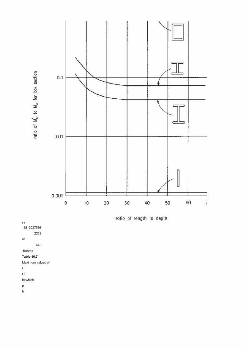
bent about their strong axis.Figure 16.7,which is based onelastic critical load theory analogous to the Euler buckling of struts,shows
le if unbraced is a prerequisite for theprovision of an effective system.Since lateral–torsional buckling involves bothlateral deectio
am would meet this requirement.Examinationof Reference 7 shows that while such a check does cover the majority of cases,it iss t

7/29/2019 Table Chair
http://slidepdf.com/reader/full/table-chair 29/322
ay.

7/29/2019 Table Chair
http://slidepdf.com/reader/full/table-chair 30/322
signed according to the principles of either elastic or plastic theory is given insection 18.7.
suming that the end frames preventlateral movement of the top ange).An approximate way of dealing with this is to regard each lo

7/29/2019 Table Chair
http://slidepdf.com/reader/full/table-chair 31/322

7/29/2019 Table Chair
http://slidepdf.com/reader/full/table-chair 32/322

7/29/2019 Table Chair
http://slidepdf.com/reader/full/table-chair 33/322
ckling strength.Similarly a cantilever subject to

7/29/2019 Table Chair
http://slidepdf.com/reader/full/table-chair 34/322
thattypical RHS beams will be of the order of ten times more stable than UB or UCsections of the same area.The limits on
and twist,as shown in Fig.16.4,either or both deformations maybe addressed.Clauses 4.3.2 and 4.3.3 of BS 5950:Part 1 set out th
ill possible to provide arrangements in which even much stiffer bracing cannotsupply full restraint.

7/29/2019 Table Chair
http://slidepdf.com/reader/full/table-chair 35/322

7/29/2019 Table Chair
http://slidepdf.com/reader/full/table-chair 36/322
ngitudinal girder as a truss in which the tension chord is fully

7/29/2019 Table Chair
http://slidepdf.com/reader/full/table-chair 37/322

7/29/2019 Table Chair
http://slidepdf.com/reader/full/table-chair 38/322

7/29/2019 Table Chair
http://slidepdf.com/reader/full/table-chair 39/322

7/29/2019 Table Chair
http://slidepdf.com/reader/full/table-chair 40/322
e principles gov-erning the action of bracing designed to provide either lateral restraint or torsionalrestraint.In common with most ap

7/29/2019 Table Chair
http://slidepdf.com/reader/full/table-chair 41/322

7/29/2019 Table Chair
http://slidepdf.com/reader/full/table-chair 42/322

7/29/2019 Table Chair
http://slidepdf.com/reader/full/table-chair 43/322

7/29/2019 Table Chair
http://slidepdf.com/reader/full/table-chair 44/322

7/29/2019 Table Chair
http://slidepdf.com/reader/full/table-chair 45/322

7/29/2019 Table Chair
http://slidepdf.com/reader/full/table-chair 46/322
proaches to bracing design these clauses assume
7/29/2019 Table Chair
http://slidepdf.com/reader/full/table-chair 47/322
Table 16.6
Types of beam not susceptible to lateral–torsional bucklingloading produces bending about the minor axisbeam provided with clos
Fig.16.4
Lateral–torsional buckling
The central feature in the above process is the determination of a measure of thebeam’s lateral–torsional buckling strength (p
b
) in terms of a parameter (
l
LT
) whichrepresents those factors which control this strength.Modications to the basicprocess permit the method to be used for une
p
b
and
l
LT
of BS 5950:Part 1 (and between
s
li
/
s
yc
and
l
LT
÷
(
s
yc
/
355
) in BS 5400:Part 3) assumes the beam between lateral restraints to besubject to uniform moment.Other patterns,such as a linear
n
,the value of which has been selected so as to ensure that theresulting value of
p
bcorrectly reects the enhanced strength due to the non-uniformmoment loading.An alternative approach consists of basing
l
LT
on the geometricaland support conditions alone but making allowance for the benecial effects of non-uniform moment by compari
M
b
with a suitably adjustedvalue of design moment
.
is taken as a factor

7/29/2019 Table Chair
http://slidepdf.com/reader/full/table-chair 48/322
m
times the maximum momentwithin the beam
M
max
;
m
=1.0 for uniform moment and
m
<
1.0 for non-uniformmoment.Provided that suitably chosen values of
m
and
n
are used,both methodscan be made to yield identical results;the difference arises simply in the way inwhich the correction is made
p
b
versus
l
LT
relationship for the
n
-factor method or on the strength axis for the
m
-factor method.Figure 16.5 illustrates both concepts,although for the purpose of the gure the
m
-factor method has been shown as an enhancement of
p
b
by 1/
m
rather than a reduc-tion in the requirement of checking
M
b
against
=
mM
max.BS 5950:Part 1 uses the
m
-factor method for all cases,while BS 5400:Part 3 includes only the
n
-factormethod.When the
m
-factor method is used the buckling check is conducted in terms of a moment less than the maximum moment in the beam segme
M
max

7/29/2019 Table Chair
http://slidepdf.com/reader/full/table-chair 49/322
;then aseparate check that the capacity of the beam cross-section
M
c
is at least equal to
M
max
must also be made.In cases where is taken asM
max
,then the bucklingcheck will be more severe than (or in the ease of a stocky beam for which
M
b
=
M
c
,identical to) the cross-section capacity check.Allowance for non-uniform moment loading on cantilevers is normally treatedsomew
M M M M M
444
Beams
an end moment such as horizontal wind load acting on a façade,should be regardedas an ordinary beam since it does not have th
M
E
.Values of
M
E
may conveniently be obtainedfrom summaries of research data.
6
For example,BS 5950:Part 1 permits
l
LT
to becalculated from
-16.3
As an example of the use of this approach Fig.16.6 shows how signicantly higherload-carrying capacities may be obtained for a c
16.3.7Fully restrained beams
The design of beams is considerably simplied if lateral–torsional buckling effectsdo not have to be considered explicitly – a situati
Mb
may be taken as itsmoment capacity
M
c
and,in the absence of any reductions in
M
c
due to local buck-
l p

7/29/2019 Table Chair
http://slidepdf.com/reader/full/table-chair 50/322
LTypE
#NAME?
( )
÷
( )
2
EpMM//
Basic design
445
Fig.16.5
Design modications using
m
-factor or
n
-factor methods
ling,high shear or torsion,it should be designed for its full in-plane bending strength.Certain of the conditions corresponding to the c
l
below which buckling will not affect
M
b
of Table 38 of BS 5950:Part 1,are sufciently high (
l
=
340,225 and 170 for
D/B
ratios of 2,3 and 4,and
p
y
=
275N/mm
2
) that only in very rare cases will lateral–torsional buckling be a design consideration.Situations in which the form of construction e
446
Beams
Fig.16.6Lateral–torsional buckling of a tip-loaded cantilever
that the restraints will effectively prevent movement at the braced cross-sections,thereby acting as if they were rigid supports.In pr
Basic design
447
Fig.16.7
Effect of type of cross-section on theoretical elastic critical moment
7/29/2019 Table Chair
http://slidepdf.com/reader/full/table-chair 51/322
16.4Lateral bracing
For design to BS 5950:Part 1,unless the engineer is prepared to supplement the coderules with some degree of working from rst
7,8
Where properly designed restraint systems areused the limits on
l
LTfor
M
b
=
M
c
(or more correctly
p
b
=
p
y
)are given in Table 16.7.For beams in plastically-designed structures it is vital that premature failure dueto plastic lateral–torsional
L
/
r
y
to ensure satisfactory behaviour;it is not necessarilycompatible with the elastic design rules of section 4 of the code since accepta
M
p
.The expression of clause 5.3.3 of BS 5950:Part 1,
-16.4
makes no allowance for either of two potentially benecial effects:(1)moment gradient(2)restraint against lateral deection provided
Lr fpx
mycy
£+
( ) ( )
[ ]
3813027536
2212
///448
Beams
Table 16.7
Maximum values of
l
LT
forwhich
p
b

7/29/2019 Table Chair
http://slidepdf.com/reader/full/table-chair 52/322
=
p
y
for rolledsections
p
y
(N/mm2
) Value of
l
LT
up to which
p
b
=
p
y
245 37265 35275 34325 32340 31365 30415 28430 27450 26
of Brown,
9
the basis of which is the original work on plastic instability of Horne.
10
This is covered explicitly in clause 5.3.3.A method of allowing for both effects whenthe beam segment being checked is either elas
L
m
with an enhanced value
L
s
obtained from clause 5.3.4 of BS 5950:Part 1.In both cases the presence of a change in cross-section,for example,as producedby
16.5Bracing action in bridges – U-frame design
The main longitudinal beams in several forms of bridge construction will,by virtueof the structural arrangement employed,receive a
U-frame
action.Figure 16.8 illustrates the original concept based on the half-through girderform of construction.(See Chapter 4 for a discuss
Bracing action in bridges
7/29/2019 Table Chair
http://slidepdf.com/reader/full/table-chair 53/322
ly spaced or continuous lateral restraintclosed section
ual anged sections including tees,fabricated Is for which the section properties must be calculated,sections contain-ing slender pl
moment gradient reduc-ing from a maximum at one end or the parabolic distribution produced by a uniformload,are generally less
ng the resulting value of

7/29/2019 Table Chair
http://slidepdf.com/reader/full/table-chair 54/322
,whether on the slenderness axis of the
t

7/29/2019 Table Chair
http://slidepdf.com/reader/full/table-chair 55/322
at differently.For example,the set of effective length factors given in Table14 of Reference 1 includes allowances for the variation f
benet of non-uniform momentloading.For more complex arrangements that cannot reasonably be approximated by oneof the sta
ntilever with a tip load applied toits bottom ange,a case not specically covered by BS 5950:Part 1.
on which will occur if one or moreof the conditions of Table 16.6 are met.In these cases the beam’s buckling resistance moment
7/29/2019 Table Chair
http://slidepdf.com/reader/full/table-chair 56/322
ase where a beam may be regardedas ‘fully restrained’ are virtually self-evident but others require either judgement orcalculation.L
ployed automatically providessome degree of lateral restraint or for which a bracing system is to be used toenhance a beam’s str
ctice,bracing will possess a nitestiffness.A more fundamental discussion of the topic,which explains the exactnature of bracing sti

7/29/2019 Table Chair
http://slidepdf.com/reader/full/table-chair 57/322
rinciples,only restraints capable of acting as rigid supports are acceptable.Despite the absence of a specic stiffnessrequirement,
uckling does not impair the formation of the full plasticcollapse mechanism and the attainment of the plastic collapse load.Clause
lebehaviour can include the provision of adequate rotation capacity at momentsslightly below
by secondary structural membersattached to one ange as by the purlins on the top ange of a portal framerafter.The rst effect

7/29/2019 Table Chair
http://slidepdf.com/reader/full/table-chair 58/322
ic or partially plastic is given inAppendix G of BS 5950:Part 1;alternatively the effect of intermittent tension angerestraint alone m
the type of haunch usually used in portal frame construction,may be allowedfor.When the restraint is such that lateral deection of t
signicant measure of restraintagainst lateral–torsional buckling by a device commonly referred to as
ion of different bridge types.) Ina simply-supported span,the top (compression) anges of the main girders,althoughlaterally unbrac

7/29/2019 Table Chair
http://slidepdf.com/reader/full/table-chair 59/322
ate elements,members with properties that vary along their length,closed sections and ats.Various techniques for allowing for the
evere in terms of their effect on lateral stability;a givenbeam is likely to be able to withstand a larger peak moment before becomin

7/29/2019 Table Chair
http://slidepdf.com/reader/full/table-chair 60/322

7/29/2019 Table Chair
http://slidepdf.com/reader/full/table-chair 61/322
rom the arrangement usedas the basis for the s trength–slenderness relationship due to both the lateral supportconditions and the f
dard cases covered by correction factors,codes normally permit the directuse of the elastic critical moment

7/29/2019 Table Chair
http://slidepdf.com/reader/full/table-chair 62/322

7/29/2019 Table Chair
http://slidepdf.com/reader/full/table-chair 63/322
dherence to the strength requirement together with an awareness thatadequate stiffness is also necessary,avoiding obviously very
.3.3provides a basic limit on
ay be included in Equation (16.4) by adding the correction term

7/29/2019 Table Chair
http://slidepdf.com/reader/full/table-chair 64/322
y be allowed for by replacing
he beam’s compressionange is prevented at intervals,then Equation (16.4) applies between the pointsof effective lateral restraint.
d in the sense that no bracing may be attached directly to them,cannot buckle freely in the manner of Fig.16.4 since their lower a
7/29/2019 Table Chair
http://slidepdf.com/reader/full/table-chair 65/322
form of the appliedloading are also possible;some care is required in their use.The relationship between
lat-erally unstable.One means of allowing for this in design is to adjust the beam’s slen-derness by a factor

7/29/2019 Table Chair
http://slidepdf.com/reader/full/table-chair 66/322

7/29/2019 Table Chair
http://slidepdf.com/reader/full/table-chair 67/322
rm of the applied loading.When a cantilever is subdivided byone or more intermediate lateral restraints positioned between its root

7/29/2019 Table Chair
http://slidepdf.com/reader/full/table-chair 68/322
collapse simply by plasticaction and excessive in-plane deformation.Much the same is true for rectangularbox sections even when
gth of themain member is that it limits the buckling type deformations.An appreciation of exactly how the main member would buc
of ‘adequatestiffness’,although it has subsequently been suggested that a bracing system that is25 times stiffer than the braced b

7/29/2019 Table Chair
http://slidepdf.com/reader/full/table-chair 69/322
exible yet strongarrangements,should lead to satisfactory designs.Doubtful cases will merit exami-nation in a more fundamental

7/29/2019 Table Chair
http://slidepdf.com/reader/full/table-chair 70/322
discussion of the application of this and otherapproaches for checking the stability of both rafters and columns in portal framesde
nges arerestrained by the deck.Buckling must therefore involve some distortion of thegirder web into the mode given in Fig.16.8 (a

7/29/2019 Table Chair
http://slidepdf.com/reader/full/table-chair 71/322

7/29/2019 Table Chair
http://slidepdf.com/reader/full/table-chair 72/322

7/29/2019 Table Chair
http://slidepdf.com/reader/full/table-chair 73/322
and tip,thensegments other than the tip segment should be treated as ordinary beam segmentswhen assessing lateral–torsional b

7/29/2019 Table Chair
http://slidepdf.com/reader/full/table-chair 74/322
bent about their strong axis.Figure 16.7,which is based onelastic critical load theory analogous to the Euler buckling of struts,shows
le if unbraced is a prerequisite for theprovision of an effective system.Since lateral–torsional buckling involves bothlateral deectio
am would meet this requirement.Examinationof Reference 7 shows that while such a check does cover the majority of cases,it iss t

7/29/2019 Table Chair
http://slidepdf.com/reader/full/table-chair 75/322
ay.

7/29/2019 Table Chair
http://slidepdf.com/reader/full/table-chair 76/322
signed according to the principles of either elastic or plastic theory is given insection 18.7.
suming that the end frames preventlateral movement of the top ange).An approximate way of dealing with this is to regard each lo

7/29/2019 Table Chair
http://slidepdf.com/reader/full/table-chair 77/322

7/29/2019 Table Chair
http://slidepdf.com/reader/full/table-chair 78/322
7/29/2019 Table Chair
http://slidepdf.com/reader/full/table-chair 79/322
ckling strength.Similarly a cantilever subject to
7/29/2019 Table Chair
http://slidepdf.com/reader/full/table-chair 80/322
thattypical RHS beams will be of the order of ten times more stable than UB or UCsections of the same area.The limits on
and twist,as shown in Fig.16.4,either or both deformations maybe addressed.Clauses 4.3.2 and 4.3.3 of BS 5950:Part 1 set out th
ill possible to provide arrangements in which even much stiffer bracing cannotsupply full restraint.

7/29/2019 Table Chair
http://slidepdf.com/reader/full/table-chair 81/322

7/29/2019 Table Chair
http://slidepdf.com/reader/full/table-chair 82/322
ngitudinal girder as a truss in which the tension chord is fully

7/29/2019 Table Chair
http://slidepdf.com/reader/full/table-chair 83/322

7/29/2019 Table Chair
http://slidepdf.com/reader/full/table-chair 84/322

7/29/2019 Table Chair
http://slidepdf.com/reader/full/table-chair 85/322

7/29/2019 Table Chair
http://slidepdf.com/reader/full/table-chair 86/322
e principles gov-erning the action of bracing designed to provide either lateral restraint or torsionalrestraint.In common with most ap

7/29/2019 Table Chair
http://slidepdf.com/reader/full/table-chair 87/322

7/29/2019 Table Chair
http://slidepdf.com/reader/full/table-chair 88/322

7/29/2019 Table Chair
http://slidepdf.com/reader/full/table-chair 89/322

7/29/2019 Table Chair
http://slidepdf.com/reader/full/table-chair 90/322

7/29/2019 Table Chair
http://slidepdf.com/reader/full/table-chair 91/322

7/29/2019 Table Chair
http://slidepdf.com/reader/full/table-chair 92/322
proaches to bracing design these clauses assume

7/29/2019 Table Chair
http://slidepdf.com/reader/full/table-chair 93/322
Table 16.6
Types of beam not susceptible to lateral–torsional bucklingloading produces bending about the minor axisbeam provided with clos
Fig.16.4
Lateral–torsional buckling
The central feature in the above process is the determination of a measure of thebeam’s lateral–torsional buckling strength (p
b
) in terms of a parameter (
l
LT
) whichrepresents those factors which control this strength.Modications to the basicprocess permit the method to be used for une
p
b
and
l
LT
of BS 5950:Part 1 (and between
s
li
/
s
yc
and
l
LT
÷
(
s
yc
/
355
) in BS 5400:Part 3) assumes the beam between lateral restraints to besubject to uniform moment.Other patterns,such as a linear
n
,the value of which has been selected so as to ensure that theresulting value of
p
bcorrectly reects the enhanced strength due to the non-uniformmoment loading.An alternative approach consists of basing
l
LT
on the geometricaland support conditions alone but making allowance for the benecial effects of non-uniform moment by compari
M
b
with a suitably adjustedvalue of design moment
.
is taken as a factor

7/29/2019 Table Chair
http://slidepdf.com/reader/full/table-chair 94/322
m
times the maximum momentwithin the beam
M
max
;
m
=1.0 for uniform moment and
m
<
1.0 for non-uniformmoment.Provided that suitably chosen values of
m
and
n
are used,both methodscan be made to yield identical results;the difference arises simply in the way inwhich the correction is made
p
b
versus
l
LT
relationship for the
n
-factor method or on the strength axis for the
m
-factor method.Figure 16.5 illustrates both concepts,although for the purpose of the gure the
m
-factor method has been shown as an enhancement of
p
b
by 1/
m
rather than a reduc-tion in the requirement of checking
M
b
against
=
mM
max.BS 5950:Part 1 uses the
m
-factor method for all cases,while BS 5400:Part 3 includes only the
n
-factormethod.When the
m
-factor method is used the buckling check is conducted in terms of a moment less than the maximum moment in the beam segme
M
max

7/29/2019 Table Chair
http://slidepdf.com/reader/full/table-chair 95/322
;then aseparate check that the capacity of the beam cross-section
M
c
is at least equal to
M
max
must also be made.In cases where is taken asM
max
,then the bucklingcheck will be more severe than (or in the ease of a stocky beam for which
M
b
=
M
c
,identical to) the cross-section capacity check.Allowance for non-uniform moment loading on cantilevers is normally treatedsomew
M M M M M
444
Beams
an end moment such as horizontal wind load acting on a façade,should be regardedas an ordinary beam since it does not have th
M
E
.Values of
M
E
may conveniently be obtainedfrom summaries of research data.
6
For example,BS 5950:Part 1 permits
l
LT
to becalculated from
-16.3
As an example of the use of this approach Fig.16.6 shows how signicantly higherload-carrying capacities may be obtained for a c
16.3.7Fully restrained beams
The design of beams is considerably simplied if lateral–torsional buckling effectsdo not have to be considered explicitly – a situati
Mb
may be taken as itsmoment capacity
M
c
and,in the absence of any reductions in
M
c
due to local buck-
l p

7/29/2019 Table Chair
http://slidepdf.com/reader/full/table-chair 96/322
LTypE
#NAME?
( )
÷
( )
2
EpMM//
Basic design
445
Fig.16.5
Design modications using
m
-factor or
n
-factor methods
ling,high shear or torsion,it should be designed for its full in-plane bending strength.Certain of the conditions corresponding to the c
l
below which buckling will not affect
M
b
of Table 38 of BS 5950:Part 1,are sufciently high (
l
=
340,225 and 170 for
D/B
ratios of 2,3 and 4,and
p
y
=
275N/mm
2
) that only in very rare cases will lateral–torsional buckling be a design consideration.Situations in which the form of construction e
446
Beams
Fig.16.6Lateral–torsional buckling of a tip-loaded cantilever
that the restraints will effectively prevent movement at the braced cross-sections,thereby acting as if they were rigid supports.In pr
Basic design
447
Fig.16.7
Effect of type of cross-section on theoretical elastic critical moment

7/29/2019 Table Chair
http://slidepdf.com/reader/full/table-chair 97/322
16.4Lateral bracing
For design to BS 5950:Part 1,unless the engineer is prepared to supplement the coderules with some degree of working from rst
7,8
Where properly designed restraint systems areused the limits on
l
LTfor
M
b
=
M
c
(or more correctly
p
b
=
p
y
)are given in Table 16.7.For beams in plastically-designed structures it is vital that premature failure dueto plastic lateral–torsional
L
/
r
y
to ensure satisfactory behaviour;it is not necessarilycompatible with the elastic design rules of section 4 of the code since accepta
M
p
.The expression of clause 5.3.3 of BS 5950:Part 1,
-16.4
makes no allowance for either of two potentially benecial effects:(1)moment gradient(2)restraint against lateral deection provided
Lr fpx
mycy
£+
( ) ( )
[ ]
3813027536
2212
///448
Beams
Table 16.7
Maximum values of
l
LT
forwhich
p
b

7/29/2019 Table Chair
http://slidepdf.com/reader/full/table-chair 98/322

7/29/2019 Table Chair
http://slidepdf.com/reader/full/table-chair 99/322
ly spaced or continuous lateral restraintclosed section
ual anged sections including tees,fabricated Is for which the section properties must be calculated,sections contain-ing slender pl
moment gradient reduc-ing from a maximum at one end or the parabolic distribution produced by a uniformload,are generally less
ng the resulting value of

7/29/2019 Table Chair
http://slidepdf.com/reader/full/table-chair 100/322
,whether on the slenderness axis of the
t

7/29/2019 Table Chair
http://slidepdf.com/reader/full/table-chair 101/322
at differently.For example,the set of effective length factors given in Table14 of Reference 1 includes allowances for the variation f
benet of non-uniform momentloading.For more complex arrangements that cannot reasonably be approximated by oneof the sta
ntilever with a tip load applied toits bottom ange,a case not specically covered by BS 5950:Part 1.
on which will occur if one or moreof the conditions of Table 16.6 are met.In these cases the beam’s buckling resistance moment

7/29/2019 Table Chair
http://slidepdf.com/reader/full/table-chair 102/322
ase where a beam may be regardedas ‘fully restrained’ are virtually self-evident but others require either judgement orcalculation.L
ployed automatically providessome degree of lateral restraint or for which a bracing system is to be used toenhance a beam’s str
ctice,bracing will possess a nitestiffness.A more fundamental discussion of the topic,which explains the exactnature of bracing sti

7/29/2019 Table Chair
http://slidepdf.com/reader/full/table-chair 103/322
rinciples,only restraints capable of acting as rigid supports are acceptable.Despite the absence of a specic stiffnessrequirement,
uckling does not impair the formation of the full plasticcollapse mechanism and the attainment of the plastic collapse load.Clause
lebehaviour can include the provision of adequate rotation capacity at momentsslightly below
by secondary structural membersattached to one ange as by the purlins on the top ange of a portal framerafter.The rst effect
7/29/2019 Table Chair
http://slidepdf.com/reader/full/table-chair 104/322
ic or partially plastic is given inAppendix G of BS 5950:Part 1;alternatively the effect of intermittent tension angerestraint alone m
the type of haunch usually used in portal frame construction,may be allowedfor.When the restraint is such that lateral deection of t
signicant measure of restraintagainst lateral–torsional buckling by a device commonly referred to as
ion of different bridge types.) Ina simply-supported span,the top (compression) anges of the main girders,althoughlaterally unbrac

7/29/2019 Table Chair
http://slidepdf.com/reader/full/table-chair 105/322
ate elements,members with properties that vary along their length,closed sections and ats.Various techniques for allowing for the
evere in terms of their effect on lateral stability;a givenbeam is likely to be able to withstand a larger peak moment before becomin

7/29/2019 Table Chair
http://slidepdf.com/reader/full/table-chair 106/322

7/29/2019 Table Chair
http://slidepdf.com/reader/full/table-chair 107/322
rom the arrangement usedas the basis for the s trength–slenderness relationship due to both the lateral supportconditions and the f
dard cases covered by correction factors,codes normally permit the directuse of the elastic critical moment

7/29/2019 Table Chair
http://slidepdf.com/reader/full/table-chair 108/322
ateral–torsional buckling cannot occur in beams loaded in their weaker princi-pal plane;under the action of increasing load they will
ngth require careful consideration.The fundamental require-ment of any form of restraint if it is to be capable of increasing the stre
fness and bracing strength,may be found in References 7 and8.Noticeably absent from the code clauses is a quantitative denition

7/29/2019 Table Chair
http://slidepdf.com/reader/full/table-chair 109/322
dherence to the strength requirement together with an awareness thatadequate stiffness is also necessary,avoiding obviously very
.3.3provides a basic limit on
ay be included in Equation (16.4) by adding the correction term

7/29/2019 Table Chair
http://slidepdf.com/reader/full/table-chair 110/322

7/29/2019 Table Chair
http://slidepdf.com/reader/full/table-chair 111/322
form of the appliedloading are also possible;some care is required in their use.The relationship between
lat-erally unstable.One means of allowing for this in design is to adjust the beam’s slen-derness by a factor

7/29/2019 Table Chair
http://slidepdf.com/reader/full/table-chair 112/322

7/29/2019 Table Chair
http://slidepdf.com/reader/full/table-chair 113/322
rm of the applied loading.When a cantilever is subdivided byone or more intermediate lateral restraints positioned between its root

7/29/2019 Table Chair
http://slidepdf.com/reader/full/table-chair 114/322
collapse simply by plasticaction and excessive in-plane deformation.Much the same is true for rectangularbox sections even when
gth of themain member is that it limits the buckling type deformations.An appreciation of exactly how the main member would buc
of ‘adequatestiffness’,although it has subsequently been suggested that a bracing system that is25 times stiffer than the braced b

7/29/2019 Table Chair
http://slidepdf.com/reader/full/table-chair 115/322
exible yet strongarrangements,should lead to satisfactory designs.Doubtful cases will merit exami-nation in a more fundamental

7/29/2019 Table Chair
http://slidepdf.com/reader/full/table-chair 116/322
discussion of the application of this and otherapproaches for checking the stability of both rafters and columns in portal framesde
nges arerestrained by the deck.Buckling must therefore involve some distortion of thegirder web into the mode given in Fig.16.8 (a

7/29/2019 Table Chair
http://slidepdf.com/reader/full/table-chair 117/322

7/29/2019 Table Chair
http://slidepdf.com/reader/full/table-chair 118/322

7/29/2019 Table Chair
http://slidepdf.com/reader/full/table-chair 119/322
and tip,thensegments other than the tip segment should be treated as ordinary beam segmentswhen assessing lateral–torsional b

7/29/2019 Table Chair
http://slidepdf.com/reader/full/table-chair 120/322
bent about their strong axis.Figure 16.7,which is based onelastic critical load theory analogous to the Euler buckling of struts,shows
le if unbraced is a prerequisite for theprovision of an effective system.Since lateral–torsional buckling involves bothlateral deectio
am would meet this requirement.Examinationof Reference 7 shows that while such a check does cover the majority of cases,it iss t

7/29/2019 Table Chair
http://slidepdf.com/reader/full/table-chair 121/322
ay.

7/29/2019 Table Chair
http://slidepdf.com/reader/full/table-chair 122/322
signed according to the principles of either elastic or plastic theory is given insection 18.7.
suming that the end frames preventlateral movement of the top ange).An approximate way of dealing with this is to regard each lo

7/29/2019 Table Chair
http://slidepdf.com/reader/full/table-chair 123/322

7/29/2019 Table Chair
http://slidepdf.com/reader/full/table-chair 124/322

7/29/2019 Table Chair
http://slidepdf.com/reader/full/table-chair 125/322
ckling strength.Similarly a cantilever subject to

7/29/2019 Table Chair
http://slidepdf.com/reader/full/table-chair 126/322
thattypical RHS beams will be of the order of ten times more stable than UB or UCsections of the same area.The limits on
and twist,as shown in Fig.16.4,either or both deformations maybe addressed.Clauses 4.3.2 and 4.3.3 of BS 5950:Part 1 set out th
ill possible to provide arrangements in which even much stiffer bracing cannotsupply full restraint.

7/29/2019 Table Chair
http://slidepdf.com/reader/full/table-chair 127/322

7/29/2019 Table Chair
http://slidepdf.com/reader/full/table-chair 128/322
ngitudinal girder as a truss in which the tension chord is fully

7/29/2019 Table Chair
http://slidepdf.com/reader/full/table-chair 129/322

7/29/2019 Table Chair
http://slidepdf.com/reader/full/table-chair 130/322

7/29/2019 Table Chair
http://slidepdf.com/reader/full/table-chair 131/322
7/29/2019 Table Chair
http://slidepdf.com/reader/full/table-chair 132/322
e principles gov-erning the action of bracing designed to provide either lateral restraint or torsionalrestraint.In common with most ap

7/29/2019 Table Chair
http://slidepdf.com/reader/full/table-chair 133/322

7/29/2019 Table Chair
http://slidepdf.com/reader/full/table-chair 134/322

7/29/2019 Table Chair
http://slidepdf.com/reader/full/table-chair 135/322

7/29/2019 Table Chair
http://slidepdf.com/reader/full/table-chair 136/322

7/29/2019 Table Chair
http://slidepdf.com/reader/full/table-chair 137/322

7/29/2019 Table Chair
http://slidepdf.com/reader/full/table-chair 138/322
proaches to bracing design these clauses assume

7/29/2019 Table Chair
http://slidepdf.com/reader/full/table-chair 139/322
Table 16.6
Types of beam not susceptible to lateral–torsional bucklingloading produces bending about the minor axisbeam provided with clos
Fig.16.4
Lateral–torsional buckling
The central feature in the above process is the determination of a measure of thebeam’s lateral–torsional buckling strength (p
b
) in terms of a parameter (
l
LT
) whichrepresents those factors which control this strength.Modications to the basicprocess permit the method to be used for une
p
b
and
l
LT
of BS 5950:Part 1 (and between
s
li
/
s
yc
and
l
LT
÷
(
s
yc
/
355
) in BS 5400:Part 3) assumes the beam between lateral restraints to besubject to uniform moment.Other patterns,such as a linear
n
,the value of which has been selected so as to ensure that theresulting value of
p
bcorrectly reects the enhanced strength due to the non-uniformmoment loading.An alternative approach consists of basing
l
LT
on the geometricaland support conditions alone but making allowance for the benecial effects of non-uniform moment by compari
M
b
with a suitably adjustedvalue of design moment
.
is taken as a factor

7/29/2019 Table Chair
http://slidepdf.com/reader/full/table-chair 140/322
m
times the maximum momentwithin the beam
M
max
;
m
=1.0 for uniform moment and
m
<
1.0 for non-uniformmoment.Provided that suitably chosen values of
m
and
n
are used,both methodscan be made to yield identical results;the difference arises simply in the way inwhich the correction is made
p
b
versus
l
LT
relationship for the
n
-factor method or on the strength axis for the
m
-factor method.Figure 16.5 illustrates both concepts,although for the purpose of the gure the
m
-factor method has been shown as an enhancement of
p
b
by 1/
m
rather than a reduc-tion in the requirement of checking
M
b
against
=
mM
max.BS 5950:Part 1 uses the
m
-factor method for all cases,while BS 5400:Part 3 includes only the
n
-factormethod.When the
m
-factor method is used the buckling check is conducted in terms of a moment less than the maximum moment in the beam segme
M
max

7/29/2019 Table Chair
http://slidepdf.com/reader/full/table-chair 141/322
;then aseparate check that the capacity of the beam cross-section
M
c
is at least equal to
M
max
must also be made.In cases where is taken asM
max
,then the bucklingcheck will be more severe than (or in the ease of a stocky beam for which
M
b
=
M
c
,identical to) the cross-section capacity check.Allowance for non-uniform moment loading on cantilevers is normally treatedsomew
M M M M M
444
Beams
an end moment such as horizontal wind load acting on a façade,should be regardedas an ordinary beam since it does not have th
M
E
.Values of
M
E
may conveniently be obtainedfrom summaries of research data.
6
For example,BS 5950:Part 1 permits
l
LT
to becalculated from
-16.3
As an example of the use of this approach Fig.16.6 shows how signicantly higherload-carrying capacities may be obtained for a c
16.3.7Fully restrained beams
The design of beams is considerably simplied if lateral–torsional buckling effectsdo not have to be considered explicitly – a situati
Mb
may be taken as itsmoment capacity
M
c
and,in the absence of any reductions in
M
c
due to local buck-
l p

7/29/2019 Table Chair
http://slidepdf.com/reader/full/table-chair 142/322
LTypE
#NAME?
( )
÷
( )
2
EpMM//
Basic design
445
Fig.16.5
Design modications using
m
-factor or
n
-factor methods
ling,high shear or torsion,it should be designed for its full in-plane bending strength.Certain of the conditions corresponding to the c
l
below which buckling will not affect
M
b
of Table 38 of BS 5950:Part 1,are sufciently high (
l
=
340,225 and 170 for
D/B
ratios of 2,3 and 4,and
p
y
=
275N/mm
2
) that only in very rare cases will lateral–torsional buckling be a design consideration.Situations in which the form of construction e
446
Beams
Fig.16.6Lateral–torsional buckling of a tip-loaded cantilever
that the restraints will effectively prevent movement at the braced cross-sections,thereby acting as if they were rigid supports.In pr
Basic design
447
Fig.16.7
Effect of type of cross-section on theoretical elastic critical moment

7/29/2019 Table Chair
http://slidepdf.com/reader/full/table-chair 143/322
16.4Lateral bracing
For design to BS 5950:Part 1,unless the engineer is prepared to supplement the coderules with some degree of working from rst
7,8
Where properly designed restraint systems areused the limits on
l
LTfor
M
b
=
M
c
(or more correctly
p
b
=
p
y
)are given in Table 16.7.For beams in plastically-designed structures it is vital that premature failure dueto plastic lateral–torsional
L
/
r
y
to ensure satisfactory behaviour;it is not necessarilycompatible with the elastic design rules of section 4 of the code since accepta
M
p
.The expression of clause 5.3.3 of BS 5950:Part 1,
-16.4
makes no allowance for either of two potentially benecial effects:(1)moment gradient(2)restraint against lateral deection provided
Lr fpx
mycy
£+
( ) ( )
[ ]
3813027536
2212
///448
Beams
Table 16.7
Maximum values of
l
LT
forwhich
p
b
7/29/2019 Table Chair
http://slidepdf.com/reader/full/table-chair 144/322
=
p
y
for rolledsections
p
y
(N/mm2
) Value of
l
LT
up to which
p
b
=
p
y
245 37265 35275 34325 32340 31365 30415 28430 27450 26
of Brown,
9
the basis of which is the original work on plastic instability of Horne.
10
This is covered explicitly in clause 5.3.3.A method of allowing for both effects whenthe beam segment being checked is either elas
L
m
with an enhanced value
L
s
obtained from clause 5.3.4 of BS 5950:Part 1.In both cases the presence of a change in cross-section,for example,as producedby
16.5Bracing action in bridges – U-frame design
The main longitudinal beams in several forms of bridge construction will,by virtueof the structural arrangement employed,receive a
U-frame
action.Figure 16.8 illustrates the original concept based on the half-through girderform of construction.(See Chapter 4 for a discuss
Bracing action in bridges

7/29/2019 Table Chair
http://slidepdf.com/reader/full/table-chair 145/322
ly spaced or continuous lateral restraintclosed section
ual anged sections including tees,fabricated Is for which the section properties must be calculated,sections contain-ing slender pl
moment gradient reduc-ing from a maximum at one end or the parabolic distribution produced by a uniformload,are generally less
ng the resulting value of

7/29/2019 Table Chair
http://slidepdf.com/reader/full/table-chair 146/322
,whether on the slenderness axis of the
t

7/29/2019 Table Chair
http://slidepdf.com/reader/full/table-chair 147/322
at differently.For example,the set of effective length factors given in Table14 of Reference 1 includes allowances for the variation f
benet of non-uniform momentloading.For more complex arrangements that cannot reasonably be approximated by oneof the sta
ntilever with a tip load applied toits bottom ange,a case not specically covered by BS 5950:Part 1.
on which will occur if one or moreof the conditions of Table 16.6 are met.In these cases the beam’s buckling resistance moment

7/29/2019 Table Chair
http://slidepdf.com/reader/full/table-chair 148/322
ase where a beam may be regardedas ‘fully restrained’ are virtually self-evident but others require either judgement orcalculation.L
ployed automatically providessome degree of lateral restraint or for which a bracing system is to be used toenhance a beam’s str
ctice,bracing will possess a nitestiffness.A more fundamental discussion of the topic,which explains the exactnature of bracing sti
7/29/2019 Table Chair
http://slidepdf.com/reader/full/table-chair 149/322
rinciples,only restraints capable of acting as rigid supports are acceptable.Despite the absence of a specic stiffnessrequirement,
uckling does not impair the formation of the full plasticcollapse mechanism and the attainment of the plastic collapse load.Clause
lebehaviour can include the provision of adequate rotation capacity at momentsslightly below
by secondary structural membersattached to one ange as by the purlins on the top ange of a portal framerafter.The rst effect

7/29/2019 Table Chair
http://slidepdf.com/reader/full/table-chair 150/322

7/29/2019 Table Chair
http://slidepdf.com/reader/full/table-chair 151/322
ate elements,members with properties that vary along their length,closed sections and ats.Various techniques for allowing for the
evere in terms of their effect on lateral stability;a givenbeam is likely to be able to withstand a larger peak moment before becomin

7/29/2019 Table Chair
http://slidepdf.com/reader/full/table-chair 152/322

7/29/2019 Table Chair
http://slidepdf.com/reader/full/table-chair 153/322
rom the arrangement usedas the basis for the s trength–slenderness relationship due to both the lateral supportconditions and the f
dard cases covered by correction factors,codes normally permit the directuse of the elastic critical moment

7/29/2019 Table Chair
http://slidepdf.com/reader/full/table-chair 154/322
ateral–torsional buckling cannot occur in beams loaded in their weaker princi-pal plane;under the action of increasing load they will
ngth require careful consideration.The fundamental require-ment of any form of restraint if it is to be capable of increasing the stre
fness and bracing strength,may be found in References 7 and8.Noticeably absent from the code clauses is a quantitative denition

7/29/2019 Table Chair
http://slidepdf.com/reader/full/table-chair 155/322
dherence to the strength requirement together with an awareness thatadequate stiffness is also necessary,avoiding obviously very
.3.3provides a basic limit on
ay be included in Equation (16.4) by adding the correction term

7/29/2019 Table Chair
http://slidepdf.com/reader/full/table-chair 156/322
y be allowed for by replacing
he beam’s compressionange is prevented at intervals,then Equation (16.4) applies between the pointsof effective lateral restraint.
d in the sense that no bracing may be attached directly to them,cannot buckle freely in the manner of Fig.16.4 since their lower a

7/29/2019 Table Chair
http://slidepdf.com/reader/full/table-chair 157/322
form of the appliedloading are also possible;some care is required in their use.The relationship between
lat-erally unstable.One means of allowing for this in design is to adjust the beam’s slen-derness by a factor

7/29/2019 Table Chair
http://slidepdf.com/reader/full/table-chair 158/322
7/29/2019 Table Chair
http://slidepdf.com/reader/full/table-chair 159/322
rm of the applied loading.When a cantilever is subdivided byone or more intermediate lateral restraints positioned between its root

7/29/2019 Table Chair
http://slidepdf.com/reader/full/table-chair 160/322
collapse simply by plasticaction and excessive in-plane deformation.Much the same is true for rectangularbox sections even when
gth of themain member is that it limits the buckling type deformations.An appreciation of exactly how the main member would buc
of ‘adequatestiffness’,although it has subsequently been suggested that a bracing system that is25 times stiffer than the braced b

7/29/2019 Table Chair
http://slidepdf.com/reader/full/table-chair 161/322
exible yet strongarrangements,should lead to satisfactory designs.Doubtful cases will merit exami-nation in a more fundamental

7/29/2019 Table Chair
http://slidepdf.com/reader/full/table-chair 162/322
discussion of the application of this and otherapproaches for checking the stability of both rafters and columns in portal framesde
nges arerestrained by the deck.Buckling must therefore involve some distortion of thegirder web into the mode given in Fig.16.8 (a

7/29/2019 Table Chair
http://slidepdf.com/reader/full/table-chair 163/322

7/29/2019 Table Chair
http://slidepdf.com/reader/full/table-chair 164/322

7/29/2019 Table Chair
http://slidepdf.com/reader/full/table-chair 165/322
and tip,thensegments other than the tip segment should be treated as ordinary beam segmentswhen assessing lateral–torsional b

7/29/2019 Table Chair
http://slidepdf.com/reader/full/table-chair 166/322
bent about their strong axis.Figure 16.7,which is based onelastic critical load theory analogous to the Euler buckling of struts,shows
le if unbraced is a prerequisite for theprovision of an effective system.Since lateral–torsional buckling involves bothlateral deectio
am would meet this requirement.Examinationof Reference 7 shows that while such a check does cover the majority of cases,it iss t

7/29/2019 Table Chair
http://slidepdf.com/reader/full/table-chair 167/322
ay.
7/29/2019 Table Chair
http://slidepdf.com/reader/full/table-chair 168/322
signed according to the principles of either elastic or plastic theory is given insection 18.7.
suming that the end frames preventlateral movement of the top ange).An approximate way of dealing with this is to regard each lo

7/29/2019 Table Chair
http://slidepdf.com/reader/full/table-chair 169/322

7/29/2019 Table Chair
http://slidepdf.com/reader/full/table-chair 170/322

7/29/2019 Table Chair
http://slidepdf.com/reader/full/table-chair 171/322
ckling strength.Similarly a cantilever subject to

7/29/2019 Table Chair
http://slidepdf.com/reader/full/table-chair 172/322
thattypical RHS beams will be of the order of ten times more stable than UB or UCsections of the same area.The limits on
and twist,as shown in Fig.16.4,either or both deformations maybe addressed.Clauses 4.3.2 and 4.3.3 of BS 5950:Part 1 set out th
ill possible to provide arrangements in which even much stiffer bracing cannotsupply full restraint.

7/29/2019 Table Chair
http://slidepdf.com/reader/full/table-chair 173/322

7/29/2019 Table Chair
http://slidepdf.com/reader/full/table-chair 174/322

7/29/2019 Table Chair
http://slidepdf.com/reader/full/table-chair 175/322

7/29/2019 Table Chair
http://slidepdf.com/reader/full/table-chair 176/322

7/29/2019 Table Chair
http://slidepdf.com/reader/full/table-chair 177/322

7/29/2019 Table Chair
http://slidepdf.com/reader/full/table-chair 178/322
e principles gov-erning the action of bracing designed to provide either lateral restraint or torsionalrestraint.In common with most ap

7/29/2019 Table Chair
http://slidepdf.com/reader/full/table-chair 179/322

7/29/2019 Table Chair
http://slidepdf.com/reader/full/table-chair 180/322

7/29/2019 Table Chair
http://slidepdf.com/reader/full/table-chair 181/322

7/29/2019 Table Chair
http://slidepdf.com/reader/full/table-chair 182/322

7/29/2019 Table Chair
http://slidepdf.com/reader/full/table-chair 183/322

7/29/2019 Table Chair
http://slidepdf.com/reader/full/table-chair 184/322
proaches to bracing design these clauses assume

7/29/2019 Table Chair
http://slidepdf.com/reader/full/table-chair 185/322
Table 16.6
Types of beam not susceptible to lateral–torsional bucklingloading produces bending about the minor axisbeam provided with clos
Fig.16.4
Lateral–torsional buckling
The central feature in the above process is the determination of a measure of thebeam’s lateral–torsional buckling strength (p
b
) in terms of a parameter (
l
LT
) whichrepresents those factors which control this strength.Modications to the basicprocess permit the method to be used for une
p
b
and
l
LT
of BS 5950:Part 1 (and between
s
li
/
s
yc
and
l
LT
÷
(
s
yc
/
355
) in BS 5400:Part 3) assumes the beam between lateral restraints to besubject to uniform moment.Other patterns,such as a linear
n
,the value of which has been selected so as to ensure that theresulting value of
p
bcorrectly reects the enhanced strength due to the non-uniformmoment loading.An alternative approach consists of basing
l
LT
on the geometricaland support conditions alone but making allowance for the benecial effects of non-uniform moment by compari
M
b
with a suitably adjustedvalue of design moment
.
is taken as a factor
7/29/2019 Table Chair
http://slidepdf.com/reader/full/table-chair 186/322
m
times the maximum momentwithin the beam
M
max
;
m
=1.0 for uniform moment and
m
<
1.0 for non-uniformmoment.Provided that suitably chosen values of
m
and
n
are used,both methodscan be made to yield identical results;the difference arises simply in the way inwhich the correction is made
p
b
versus
l
LT
relationship for the
n
-factor method or on the strength axis for the
m
-factor method.Figure 16.5 illustrates both concepts,although for the purpose of the gure the
m
-factor method has been shown as an enhancement of
p
b
by 1/
m
rather than a reduc-tion in the requirement of checking
M
b
against
=
mM
max.BS 5950:Part 1 uses the
m
-factor method for all cases,while BS 5400:Part 3 includes only the
n
-factormethod.When the
m
-factor method is used the buckling check is conducted in terms of a moment less than the maximum moment in the beam segme
M
max

7/29/2019 Table Chair
http://slidepdf.com/reader/full/table-chair 187/322
;then aseparate check that the capacity of the beam cross-section
M
c
is at least equal to
M
max
must also be made.In cases where is taken asM
max
,then the bucklingcheck will be more severe than (or in the ease of a stocky beam for which
M
b
=
M
c
,identical to) the cross-section capacity check.Allowance for non-uniform moment loading on cantilevers is normally treatedsomew
M M M M M
444
Beams
an end moment such as horizontal wind load acting on a façade,should be regardedas an ordinary beam since it does not have th
M
E
.Values of
M
E
may conveniently be obtainedfrom summaries of research data.
6
For example,BS 5950:Part 1 permits
l
LT
to becalculated from
-16.3
As an example of the use of this approach Fig.16.6 shows how signicantly higherload-carrying capacities may be obtained for a c
16.3.7Fully restrained beams
The design of beams is considerably simplied if lateral–torsional buckling effectsdo not have to be considered explicitly – a situati
Mb
may be taken as itsmoment capacity
M
c
and,in the absence of any reductions in
M
c
due to local buck-
l p

7/29/2019 Table Chair
http://slidepdf.com/reader/full/table-chair 188/322
LTypE
#NAME?
( )
÷
( )
2
EpMM//
Basic design
445
Fig.16.5
Design modications using
m
-factor or
n
-factor methods
ling,high shear or torsion,it should be designed for its full in-plane bending strength.Certain of the conditions corresponding to the c
l
below which buckling will not affect
M
b
of Table 38 of BS 5950:Part 1,are sufciently high (
l
=
340,225 and 170 for
D/B
ratios of 2,3 and 4,and
p
y
=
275N/mm
2
) that only in very rare cases will lateral–torsional buckling be a design consideration.Situations in which the form of construction e
446
Beams
Fig.16.6Lateral–torsional buckling of a tip-loaded cantilever
that the restraints will effectively prevent movement at the braced cross-sections,thereby acting as if they were rigid supports.In pr
Basic design
447
Fig.16.7
Effect of type of cross-section on theoretical elastic critical moment

7/29/2019 Table Chair
http://slidepdf.com/reader/full/table-chair 189/322
16.4Lateral bracing
For design to BS 5950:Part 1,unless the engineer is prepared to supplement the coderules with some degree of working from rst
7,8
Where properly designed restraint systems areused the limits on
l
LTfor
M
b
=
M
c
(or more correctly
p
b
=
p
y
)are given in Table 16.7.For beams in plastically-designed structures it is vital that premature failure dueto plastic lateral–torsional
L
/
r
y
to ensure satisfactory behaviour;it is not necessarilycompatible with the elastic design rules of section 4 of the code since accepta
M
p
.The expression of clause 5.3.3 of BS 5950:Part 1,
-16.4
makes no allowance for either of two potentially benecial effects:(1)moment gradient(2)restraint against lateral deection provided
Lr fpx
mycy
£+
( ) ( )
[ ]
3813027536
2212
///448
Beams
Table 16.7
Maximum values of
l
LT
forwhich
p
b

7/29/2019 Table Chair
http://slidepdf.com/reader/full/table-chair 190/322
=
p
y
for rolledsections
p
y
(N/mm2
) Value of
l
LT
up to which
p
b
=
p
y
245 37265 35275 34325 32340 31365 30415 28430 27450 26
of Brown,
9
the basis of which is the original work on plastic instability of Horne.
10
This is covered explicitly in clause 5.3.3.A method of allowing for both effects whenthe beam segment being checked is either elas
L
m
with an enhanced value
L
s
obtained from clause 5.3.4 of BS 5950:Part 1.In both cases the presence of a change in cross-section,for example,as producedby
16.5Bracing action in bridges – U-frame design
The main longitudinal beams in several forms of bridge construction will,by virtueof the structural arrangement employed,receive a
U-frame
action.Figure 16.8 illustrates the original concept based on the half-through girderform of construction.(See Chapter 4 for a discuss
Bracing action in bridges

7/29/2019 Table Chair
http://slidepdf.com/reader/full/table-chair 191/322
ly spaced or continuous lateral restraintclosed section
ual anged sections including tees,fabricated Is for which the section properties must be calculated,sections contain-ing slender pl
moment gradient reduc-ing from a maximum at one end or the parabolic distribution produced by a uniformload,are generally less
ng the resulting value of
7/29/2019 Table Chair
http://slidepdf.com/reader/full/table-chair 192/322
,whether on the slenderness axis of the
t

7/29/2019 Table Chair
http://slidepdf.com/reader/full/table-chair 193/322

7/29/2019 Table Chair
http://slidepdf.com/reader/full/table-chair 194/322
ase where a beam may be regardedas ‘fully restrained’ are virtually self-evident but others require either judgement orcalculation.L
ployed automatically providessome degree of lateral restraint or for which a bracing system is to be used toenhance a beam’s str
ctice,bracing will possess a nitestiffness.A more fundamental discussion of the topic,which explains the exactnature of bracing sti

7/29/2019 Table Chair
http://slidepdf.com/reader/full/table-chair 195/322
rinciples,only restraints capable of acting as rigid supports are acceptable.Despite the absence of a specic stiffnessrequirement,
uckling does not impair the formation of the full plasticcollapse mechanism and the attainment of the plastic collapse load.Clause
lebehaviour can include the provision of adequate rotation capacity at momentsslightly below
by secondary structural membersattached to one ange as by the purlins on the top ange of a portal framerafter.The rst effect

7/29/2019 Table Chair
http://slidepdf.com/reader/full/table-chair 196/322
ic or partially plastic is given inAppendix G of BS 5950:Part 1;alternatively the effect of intermittent tension angerestraint alone m
the type of haunch usually used in portal frame construction,may be allowedfor.When the restraint is such that lateral deection of t
signicant measure of restraintagainst lateral–torsional buckling by a device commonly referred to as
ion of different bridge types.) Ina simply-supported span,the top (compression) anges of the main girders,althoughlaterally unbrac

7/29/2019 Table Chair
http://slidepdf.com/reader/full/table-chair 197/322
ate elements,members with properties that vary along their length,closed sections and ats.Various techniques for allowing for the
evere in terms of their effect on lateral stability;a givenbeam is likely to be able to withstand a larger peak moment before becomin

7/29/2019 Table Chair
http://slidepdf.com/reader/full/table-chair 198/322

7/29/2019 Table Chair
http://slidepdf.com/reader/full/table-chair 199/322
rom the arrangement usedas the basis for the s trength–slenderness relationship due to both the lateral supportconditions and the f
dard cases covered by correction factors,codes normally permit the directuse of the elastic critical moment

7/29/2019 Table Chair
http://slidepdf.com/reader/full/table-chair 200/322
ateral–torsional buckling cannot occur in beams loaded in their weaker princi-pal plane;under the action of increasing load they will
ngth require careful consideration.The fundamental require-ment of any form of restraint if it is to be capable of increasing the stre
fness and bracing strength,may be found in References 7 and8.Noticeably absent from the code clauses is a quantitative denition

7/29/2019 Table Chair
http://slidepdf.com/reader/full/table-chair 201/322
dherence to the strength requirement together with an awareness thatadequate stiffness is also necessary,avoiding obviously very
.3.3provides a basic limit on
ay be included in Equation (16.4) by adding the correction term

7/29/2019 Table Chair
http://slidepdf.com/reader/full/table-chair 202/322
y be allowed for by replacing
he beam’s compressionange is prevented at intervals,then Equation (16.4) applies between the pointsof effective lateral restraint.
d in the sense that no bracing may be attached directly to them,cannot buckle freely in the manner of Fig.16.4 since their lower a

7/29/2019 Table Chair
http://slidepdf.com/reader/full/table-chair 203/322
form of the appliedloading are also possible;some care is required in their use.The relationship between
lat-erally unstable.One means of allowing for this in design is to adjust the beam’s slen-derness by a factor

7/29/2019 Table Chair
http://slidepdf.com/reader/full/table-chair 204/322

7/29/2019 Table Chair
http://slidepdf.com/reader/full/table-chair 205/322
rm of the applied loading.When a cantilever is subdivided byone or more intermediate lateral restraints positioned between its root

7/29/2019 Table Chair
http://slidepdf.com/reader/full/table-chair 206/322
collapse simply by plasticaction and excessive in-plane deformation.Much the same is true for rectangularbox sections even when
gth of themain member is that it limits the buckling type deformations.An appreciation of exactly how the main member would buc
of ‘adequatestiffness’,although it has subsequently been suggested that a bracing system that is25 times stiffer than the braced b

7/29/2019 Table Chair
http://slidepdf.com/reader/full/table-chair 207/322
exible yet strongarrangements,should lead to satisfactory designs.Doubtful cases will merit exami-nation in a more fundamental

7/29/2019 Table Chair
http://slidepdf.com/reader/full/table-chair 208/322
discussion of the application of this and otherapproaches for checking the stability of both rafters and columns in portal framesde
nges arerestrained by the deck.Buckling must therefore involve some distortion of thegirder web into the mode given in Fig.16.8 (a

7/29/2019 Table Chair
http://slidepdf.com/reader/full/table-chair 209/322

7/29/2019 Table Chair
http://slidepdf.com/reader/full/table-chair 210/322

7/29/2019 Table Chair
http://slidepdf.com/reader/full/table-chair 211/322
and tip,thensegments other than the tip segment should be treated as ordinary beam segmentswhen assessing lateral–torsional b

7/29/2019 Table Chair
http://slidepdf.com/reader/full/table-chair 212/322
bent about their strong axis.Figure 16.7,which is based onelastic critical load theory analogous to the Euler buckling of struts,shows
le if unbraced is a prerequisite for theprovision of an effective system.Since lateral–torsional buckling involves bothlateral deectio
am would meet this requirement.Examinationof Reference 7 shows that while such a check does cover the majority of cases,it iss t

7/29/2019 Table Chair
http://slidepdf.com/reader/full/table-chair 213/322
ay.

7/29/2019 Table Chair
http://slidepdf.com/reader/full/table-chair 214/322
signed according to the principles of either elastic or plastic theory is given insection 18.7.
suming that the end frames preventlateral movement of the top ange).An approximate way of dealing with this is to regard each lo

7/29/2019 Table Chair
http://slidepdf.com/reader/full/table-chair 215/322

7/29/2019 Table Chair
http://slidepdf.com/reader/full/table-chair 216/322

7/29/2019 Table Chair
http://slidepdf.com/reader/full/table-chair 217/322
ckling strength.Similarly a cantilever subject to

7/29/2019 Table Chair
http://slidepdf.com/reader/full/table-chair 218/322
thattypical RHS beams will be of the order of ten times more stable than UB or UCsections of the same area.The limits on
and twist,as shown in Fig.16.4,either or both deformations maybe addressed.Clauses 4.3.2 and 4.3.3 of BS 5950:Part 1 set out th
ill possible to provide arrangements in which even much stiffer bracing cannotsupply full restraint.

7/29/2019 Table Chair
http://slidepdf.com/reader/full/table-chair 219/322

7/29/2019 Table Chair
http://slidepdf.com/reader/full/table-chair 220/322

7/29/2019 Table Chair
http://slidepdf.com/reader/full/table-chair 221/322

7/29/2019 Table Chair
http://slidepdf.com/reader/full/table-chair 222/322

7/29/2019 Table Chair
http://slidepdf.com/reader/full/table-chair 223/322

7/29/2019 Table Chair
http://slidepdf.com/reader/full/table-chair 224/322
e principles gov-erning the action of bracing designed to provide either lateral restraint or torsionalrestraint.In common with most ap

7/29/2019 Table Chair
http://slidepdf.com/reader/full/table-chair 225/322

7/29/2019 Table Chair
http://slidepdf.com/reader/full/table-chair 226/322

7/29/2019 Table Chair
http://slidepdf.com/reader/full/table-chair 227/322

7/29/2019 Table Chair
http://slidepdf.com/reader/full/table-chair 228/322

7/29/2019 Table Chair
http://slidepdf.com/reader/full/table-chair 229/322

7/29/2019 Table Chair
http://slidepdf.com/reader/full/table-chair 230/322
proaches to bracing design these clauses assume

7/29/2019 Table Chair
http://slidepdf.com/reader/full/table-chair 231/322
Table 16.6
Types of beam not susceptible to lateral–torsional bucklingloading produces bending about the minor axisbeam provided with clos
Fig.16.4
Lateral–torsional buckling
The central feature in the above process is the determination of a measure of thebeam’s lateral–torsional buckling strength (p
b
) in terms of a parameter (
l
LT
) whichrepresents those factors which control this strength.Modications to the basicprocess permit the method to be used for une
p
b
and
l
LT
of BS 5950:Part 1 (and between
s
li
/
s
yc
and
l
LT
÷
(
s
yc
/
355
) in BS 5400:Part 3) assumes the beam between lateral restraints to besubject to uniform moment.Other patterns,such as a linear
n
,the value of which has been selected so as to ensure that theresulting value of
p
bcorrectly reects the enhanced strength due to the non-uniformmoment loading.An alternative approach consists of basing
l
LT
on the geometricaland support conditions alone but making allowance for the benecial effects of non-uniform moment by compari
M
b
with a suitably adjustedvalue of design moment
.
is taken as a factor

7/29/2019 Table Chair
http://slidepdf.com/reader/full/table-chair 232/322
m
times the maximum momentwithin the beam
M
max
;
m
=1.0 for uniform moment and
m
<
1.0 for non-uniformmoment.Provided that suitably chosen values of
m
and
n
are used,both methodscan be made to yield identical results;the difference arises simply in the way inwhich the correction is made
p
b
versus
l
LT
relationship for the
n
-factor method or on the strength axis for the
m
-factor method.Figure 16.5 illustrates both concepts,although for the purpose of the gure the
m
-factor method has been shown as an enhancement of
p
b
by 1/
m
rather than a reduc-tion in the requirement of checking
M
b
against
=
mM
max.BS 5950:Part 1 uses the
m
-factor method for all cases,while BS 5400:Part 3 includes only the
n
-factormethod.When the
m
-factor method is used the buckling check is conducted in terms of a moment less than the maximum moment in the beam segme
M
max
7/29/2019 Table Chair
http://slidepdf.com/reader/full/table-chair 233/322
;then aseparate check that the capacity of the beam cross-section
M
c
is at least equal to
M
max
must also be made.In cases where is taken asM
max
,then the bucklingcheck will be more severe than (or in the ease of a stocky beam for which
M
b
=
M
c
,identical to) the cross-section capacity check.Allowance for non-uniform moment loading on cantilevers is normally treatedsomew
M M M M M
444
Beams
an end moment such as horizontal wind load acting on a façade,should be regardedas an ordinary beam since it does not have th
M
E
.Values of
M
E
may conveniently be obtainedfrom summaries of research data.
6
For example,BS 5950:Part 1 permits
l
LT
to becalculated from
-16.3
As an example of the use of this approach Fig.16.6 shows how signicantly higherload-carrying capacities may be obtained for a c
16.3.7Fully restrained beams
The design of beams is considerably simplied if lateral–torsional buckling effectsdo not have to be considered explicitly – a situati
Mb
may be taken as itsmoment capacity
M
c
and,in the absence of any reductions in
M
c
due to local buck-
l p

7/29/2019 Table Chair
http://slidepdf.com/reader/full/table-chair 234/322
LTypE
#NAME?
( )
÷
( )
2
EpMM//
Basic design
445
Fig.16.5
Design modications using
m
-factor or
n
-factor methods
ling,high shear or torsion,it should be designed for its full in-plane bending strength.Certain of the conditions corresponding to the c
l
below which buckling will not affect
M
b
of Table 38 of BS 5950:Part 1,are sufciently high (
l
=
340,225 and 170 for
D/B
ratios of 2,3 and 4,and
p
y
=
275N/mm
2
) that only in very rare cases will lateral–torsional buckling be a design consideration.Situations in which the form of construction e
446
Beams
Fig.16.6Lateral–torsional buckling of a tip-loaded cantilever
that the restraints will effectively prevent movement at the braced cross-sections,thereby acting as if they were rigid supports.In pr
Basic design
447
Fig.16.7
Effect of type of cross-section on theoretical elastic critical moment

7/29/2019 Table Chair
http://slidepdf.com/reader/full/table-chair 235/322
16.4Lateral bracing
For design to BS 5950:Part 1,unless the engineer is prepared to supplement the coderules with some degree of working from rst
7,8
Where properly designed restraint systems areused the limits on
l
LTfor
M
b
=
M
c
(or more correctly
p
b
=
p
y
)are given in Table 16.7.For beams in plastically-designed structures it is vital that premature failure dueto plastic lateral–torsional
L
/
r
y
to ensure satisfactory behaviour;it is not necessarilycompatible with the elastic design rules of section 4 of the code since accepta
M
p
.The expression of clause 5.3.3 of BS 5950:Part 1,
-16.4
makes no allowance for either of two potentially benecial effects:(1)moment gradient(2)restraint against lateral deection provided
Lr fpx
mycy
£+
( ) ( )
[ ]
3813027536
2212
///448
Beams
Table 16.7
Maximum values of
l
LT
forwhich
p
b

7/29/2019 Table Chair
http://slidepdf.com/reader/full/table-chair 236/322
=
p
y
for rolledsections
p
y
(N/mm2
) Value of
l
LT
up to which
p
b
=
p
y
245 37265 35275 34325 32340 31365 30415 28430 27450 26
of Brown,
9
the basis of which is the original work on plastic instability of Horne.
10
This is covered explicitly in clause 5.3.3.A method of allowing for both effects whenthe beam segment being checked is either elas
L
m
with an enhanced value
L
s
obtained from clause 5.3.4 of BS 5950:Part 1.In both cases the presence of a change in cross-section,for example,as producedby
16.5Bracing action in bridges – U-frame design
The main longitudinal beams in several forms of bridge construction will,by virtueof the structural arrangement employed,receive a
U-frame
action.Figure 16.8 illustrates the original concept based on the half-through girderform of construction.(See Chapter 4 for a discuss
Bracing action in bridges

7/29/2019 Table Chair
http://slidepdf.com/reader/full/table-chair 237/322
ly spaced or continuous lateral restraintclosed section
ual anged sections including tees,fabricated Is for which the section properties must be calculated,sections contain-ing slender pl
moment gradient reduc-ing from a maximum at one end or the parabolic distribution produced by a uniformload,are generally less
ng the resulting value of

7/29/2019 Table Chair
http://slidepdf.com/reader/full/table-chair 238/322
,whether on the slenderness axis of the
t

7/29/2019 Table Chair
http://slidepdf.com/reader/full/table-chair 239/322
at differently.For example,the set of effective length factors given in Table14 of Reference 1 includes allowances for the variation f
benet of non-uniform momentloading.For more complex arrangements that cannot reasonably be approximated by oneof the sta
ntilever with a tip load applied toits bottom ange,a case not specically covered by BS 5950:Part 1.
on which will occur if one or moreof the conditions of Table 16.6 are met.In these cases the beam’s buckling resistance moment

7/29/2019 Table Chair
http://slidepdf.com/reader/full/table-chair 240/322
ase where a beam may be regardedas ‘fully restrained’ are virtually self-evident but others require either judgement orcalculation.L
ployed automatically providessome degree of lateral restraint or for which a bracing system is to be used toenhance a beam’s str
ctice,bracing will possess a nitestiffness.A more fundamental discussion of the topic,which explains the exactnature of bracing sti

7/29/2019 Table Chair
http://slidepdf.com/reader/full/table-chair 241/322
rinciples,only restraints capable of acting as rigid supports are acceptable.Despite the absence of a specic stiffnessrequirement,
uckling does not impair the formation of the full plasticcollapse mechanism and the attainment of the plastic collapse load.Clause
lebehaviour can include the provision of adequate rotation capacity at momentsslightly below
by secondary structural membersattached to one ange as by the purlins on the top ange of a portal framerafter.The rst effect

7/29/2019 Table Chair
http://slidepdf.com/reader/full/table-chair 242/322

7/29/2019 Table Chair
http://slidepdf.com/reader/full/table-chair 243/322
ate elements,members with properties that vary along their length,closed sections and ats.Various techniques for allowing for the
evere in terms of their effect on lateral stability;a givenbeam is likely to be able to withstand a larger peak moment before becomin

7/29/2019 Table Chair
http://slidepdf.com/reader/full/table-chair 244/322
7/29/2019 Table Chair
http://slidepdf.com/reader/full/table-chair 245/322
rom the arrangement usedas the basis for the s trength–slenderness relationship due to both the lateral supportconditions and the f
dard cases covered by correction factors,codes normally permit the directuse of the elastic critical moment

7/29/2019 Table Chair
http://slidepdf.com/reader/full/table-chair 246/322
ateral–torsional buckling cannot occur in beams loaded in their weaker princi-pal plane;under the action of increasing load they will
ngth require careful consideration.The fundamental require-ment of any form of restraint if it is to be capable of increasing the stre
fness and bracing strength,may be found in References 7 and8.Noticeably absent from the code clauses is a quantitative denition

7/29/2019 Table Chair
http://slidepdf.com/reader/full/table-chair 247/322
dherence to the strength requirement together with an awareness thatadequate stiffness is also necessary,avoiding obviously very
.3.3provides a basic limit on
ay be included in Equation (16.4) by adding the correction term
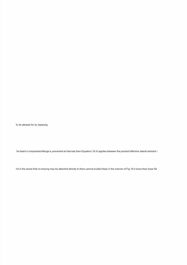
7/29/2019 Table Chair
http://slidepdf.com/reader/full/table-chair 248/322
y be allowed for by replacing
he beam’s compressionange is prevented at intervals,then Equation (16.4) applies between the pointsof effective lateral restraint.
d in the sense that no bracing may be attached directly to them,cannot buckle freely in the manner of Fig.16.4 since their lower a

7/29/2019 Table Chair
http://slidepdf.com/reader/full/table-chair 249/322
form of the appliedloading are also possible;some care is required in their use.The relationship between
lat-erally unstable.One means of allowing for this in design is to adjust the beam’s slen-derness by a factor

7/29/2019 Table Chair
http://slidepdf.com/reader/full/table-chair 250/322

7/29/2019 Table Chair
http://slidepdf.com/reader/full/table-chair 251/322
rm of the applied loading.When a cantilever is subdivided byone or more intermediate lateral restraints positioned between its root

7/29/2019 Table Chair
http://slidepdf.com/reader/full/table-chair 252/322
collapse simply by plasticaction and excessive in-plane deformation.Much the same is true for rectangularbox sections even when
gth of themain member is that it limits the buckling type deformations.An appreciation of exactly how the main member would buc
of ‘adequatestiffness’,although it has subsequently been suggested that a bracing system that is25 times stiffer than the braced b

7/29/2019 Table Chair
http://slidepdf.com/reader/full/table-chair 253/322
exible yet strongarrangements,should lead to satisfactory designs.Doubtful cases will merit exami-nation in a more fundamental

7/29/2019 Table Chair
http://slidepdf.com/reader/full/table-chair 254/322
discussion of the application of this and otherapproaches for checking the stability of both rafters and columns in portal framesde
nges arerestrained by the deck.Buckling must therefore involve some distortion of thegirder web into the mode given in Fig.16.8 (a

7/29/2019 Table Chair
http://slidepdf.com/reader/full/table-chair 255/322

7/29/2019 Table Chair
http://slidepdf.com/reader/full/table-chair 256/322

7/29/2019 Table Chair
http://slidepdf.com/reader/full/table-chair 257/322
and tip,thensegments other than the tip segment should be treated as ordinary beam segmentswhen assessing lateral–torsional b

7/29/2019 Table Chair
http://slidepdf.com/reader/full/table-chair 258/322
bent about their strong axis.Figure 16.7,which is based onelastic critical load theory analogous to the Euler buckling of struts,shows
le if unbraced is a prerequisite for theprovision of an effective system.Since lateral–torsional buckling involves bothlateral deectio
am would meet this requirement.Examinationof Reference 7 shows that while such a check does cover the majority of cases,it iss t

7/29/2019 Table Chair
http://slidepdf.com/reader/full/table-chair 259/322
ay.

7/29/2019 Table Chair
http://slidepdf.com/reader/full/table-chair 260/322
signed according to the principles of either elastic or plastic theory is given insection 18.7.
suming that the end frames preventlateral movement of the top ange).An approximate way of dealing with this is to regard each lo

7/29/2019 Table Chair
http://slidepdf.com/reader/full/table-chair 261/322

7/29/2019 Table Chair
http://slidepdf.com/reader/full/table-chair 262/322

7/29/2019 Table Chair
http://slidepdf.com/reader/full/table-chair 263/322
ckling strength.Similarly a cantilever subject to

7/29/2019 Table Chair
http://slidepdf.com/reader/full/table-chair 264/322
thattypical RHS beams will be of the order of ten times more stable than UB or UCsections of the same area.The limits on
and twist,as shown in Fig.16.4,either or both deformations maybe addressed.Clauses 4.3.2 and 4.3.3 of BS 5950:Part 1 set out th
ill possible to provide arrangements in which even much stiffer bracing cannotsupply full restraint.

7/29/2019 Table Chair
http://slidepdf.com/reader/full/table-chair 265/322
7/29/2019 Table Chair
http://slidepdf.com/reader/full/table-chair 266/322
ngitudinal girder as a truss in which the tension chord is fully

7/29/2019 Table Chair
http://slidepdf.com/reader/full/table-chair 267/322

7/29/2019 Table Chair
http://slidepdf.com/reader/full/table-chair 268/322

7/29/2019 Table Chair
http://slidepdf.com/reader/full/table-chair 269/322

7/29/2019 Table Chair
http://slidepdf.com/reader/full/table-chair 270/322
e principles gov-erning the action of bracing designed to provide either lateral restraint or torsionalrestraint.In common with most ap

7/29/2019 Table Chair
http://slidepdf.com/reader/full/table-chair 271/322

7/29/2019 Table Chair
http://slidepdf.com/reader/full/table-chair 272/322

7/29/2019 Table Chair
http://slidepdf.com/reader/full/table-chair 273/322

7/29/2019 Table Chair
http://slidepdf.com/reader/full/table-chair 274/322

7/29/2019 Table Chair
http://slidepdf.com/reader/full/table-chair 275/322

7/29/2019 Table Chair
http://slidepdf.com/reader/full/table-chair 276/322
proaches to bracing design these clauses assume

7/29/2019 Table Chair
http://slidepdf.com/reader/full/table-chair 277/322
Table 16.6
Types of beam not susceptible to lateral–torsional bucklingloading produces bending about the minor axisbeam provided with clos
Fig.16.4
Lateral–torsional buckling
The central feature in the above process is the determination of a measure of thebeam’s lateral–torsional buckling strength (p
b
) in terms of a parameter (
l
LT
) whichrepresents those factors which control this strength.Modications to the basicprocess permit the method to be used for une
p
b
and
l
LT
of BS 5950:Part 1 (and between
s
li
/
s
yc
and
l
LT
÷
(
s
yc
/
355
) in BS 5400:Part 3) assumes the beam between lateral restraints to besubject to uniform moment.Other patterns,such as a linear
n
,the value of which has been selected so as to ensure that theresulting value of
p
bcorrectly reects the enhanced strength due to the non-uniformmoment loading.An alternative approach consists of basing
l
LT
on the geometricaland support conditions alone but making allowance for the benecial effects of non-uniform moment by compari
M
b
with a suitably adjustedvalue of design moment
.
is taken as a factor

7/29/2019 Table Chair
http://slidepdf.com/reader/full/table-chair 278/322
m
times the maximum momentwithin the beam
M
max
;
m
=1.0 for uniform moment and
m
<
1.0 for non-uniformmoment.Provided that suitably chosen values of
m
and
n
are used,both methodscan be made to yield identical results;the difference arises simply in the way inwhich the correction is made
p
b
versus
l
LT
relationship for the
n
-factor method or on the strength axis for the
m
-factor method.Figure 16.5 illustrates both concepts,although for the purpose of the gure the
m
-factor method has been shown as an enhancement of
p
b
by 1/
m
rather than a reduc-tion in the requirement of checking
M
b
against
=
mM
max.BS 5950:Part 1 uses the
m
-factor method for all cases,while BS 5400:Part 3 includes only the
n
-factormethod.When the
m
-factor method is used the buckling check is conducted in terms of a moment less than the maximum moment in the beam segme
M
max

7/29/2019 Table Chair
http://slidepdf.com/reader/full/table-chair 279/322
;then aseparate check that the capacity of the beam cross-section
M
c
is at least equal to
M
max
must also be made.In cases where is taken asM
max
,then the bucklingcheck will be more severe than (or in the ease of a stocky beam for which
M
b
=
M
c
,identical to) the cross-section capacity check.Allowance for non-uniform moment loading on cantilevers is normally treatedsomew
M M M M M
444
Beams
an end moment such as horizontal wind load acting on a façade,should be regardedas an ordinary beam since it does not have th
M
E
.Values of
M
E
may conveniently be obtainedfrom summaries of research data.
6
For example,BS 5950:Part 1 permits
l
LT
to becalculated from
-16.3
As an example of the use of this approach Fig.16.6 shows how signicantly higherload-carrying capacities may be obtained for a c
16.3.7Fully restrained beams
The design of beams is considerably simplied if lateral–torsional buckling effectsdo not have to be considered explicitly – a situati
Mb
may be taken as itsmoment capacity
M
c
and,in the absence of any reductions in
M
c
due to local buck-
l p
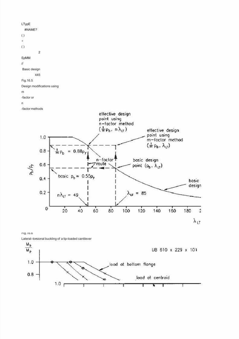
7/29/2019 Table Chair
http://slidepdf.com/reader/full/table-chair 280/322
LTypE
#NAME?
( )
÷
( )
2
EpMM//
Basic design
445
Fig.16.5
Design modications using
m
-factor or
n
-factor methods
ling,high shear or torsion,it should be designed for its full in-plane bending strength.Certain of the conditions corresponding to the c
l
below which buckling will not affect
M
b
of Table 38 of BS 5950:Part 1,are sufciently high (
l
=
340,225 and 170 for
D/B
ratios of 2,3 and 4,and
p
y
=
275N/mm
2
) that only in very rare cases will lateral–torsional buckling be a design consideration.Situations in which the form of construction e
446
Beams
Fig.16.6Lateral–torsional buckling of a tip-loaded cantilever
that the restraints will effectively prevent movement at the braced cross-sections,thereby acting as if they were rigid supports.In pr
Basic design
447
Fig.16.7
Effect of type of cross-section on theoretical elastic critical moment

7/29/2019 Table Chair
http://slidepdf.com/reader/full/table-chair 281/322
16.4Lateral bracing
For design to BS 5950:Part 1,unless the engineer is prepared to supplement the coderules with some degree of working from rst
7,8
Where properly designed restraint systems areused the limits on
l
LTfor
M
b
=
M
c
(or more correctly
p
b
=
p
y
)are given in Table 16.7.For beams in plastically-designed structures it is vital that premature failure dueto plastic lateral–torsional
L
/
r
y
to ensure satisfactory behaviour;it is not necessarilycompatible with the elastic design rules of section 4 of the code since accepta
M
p
.The expression of clause 5.3.3 of BS 5950:Part 1,
-16.4
makes no allowance for either of two potentially benecial effects:(1)moment gradient(2)restraint against lateral deection provided
Lr fpx
mycy
£+
( ) ( )
[ ]
3813027536
2212
///448
Beams
Table 16.7
Maximum values of
l
LT
forwhich
p
b

7/29/2019 Table Chair
http://slidepdf.com/reader/full/table-chair 282/322
=
p
y
for rolledsections
p
y
(N/mm2
) Value of
l
LT
up to which
p
b
=
p
y
245 37265 35275 34325 32340 31365 30415 28430 27450 26
of Brown,
9
the basis of which is the original work on plastic instability of Horne.
10
This is covered explicitly in clause 5.3.3.A method of allowing for both effects whenthe beam segment being checked is either elas
L
m
with an enhanced value
L
s
obtained from clause 5.3.4 of BS 5950:Part 1.In both cases the presence of a change in cross-section,for example,as producedby
16.5Bracing action in bridges – U-frame design
The main longitudinal beams in several forms of bridge construction will,by virtueof the structural arrangement employed,receive a
U-frame
action.Figure 16.8 illustrates the original concept based on the half-through girderform of construction.(See Chapter 4 for a discuss
Bracing action in bridges

7/29/2019 Table Chair
http://slidepdf.com/reader/full/table-chair 283/322
ly spaced or continuous lateral restraintclosed section
ual anged sections including tees,fabricated Is for which the section properties must be calculated,sections contain-ing slender pl
moment gradient reduc-ing from a maximum at one end or the parabolic distribution produced by a uniformload,are generally less
ng the resulting value of

7/29/2019 Table Chair
http://slidepdf.com/reader/full/table-chair 284/322
,whether on the slenderness axis of the
t

7/29/2019 Table Chair
http://slidepdf.com/reader/full/table-chair 285/322
at differently.For example,the set of effective length factors given in Table14 of Reference 1 includes allowances for the variation f
benet of non-uniform momentloading.For more complex arrangements that cannot reasonably be approximated by oneof the sta
ntilever with a tip load applied toits bottom ange,a case not specically covered by BS 5950:Part 1.
on which will occur if one or moreof the conditions of Table 16.6 are met.In these cases the beam’s buckling resistance moment

7/29/2019 Table Chair
http://slidepdf.com/reader/full/table-chair 286/322
ase where a beam may be regardedas ‘fully restrained’ are virtually self-evident but others require either judgement orcalculation.L
ployed automatically providessome degree of lateral restraint or for which a bracing system is to be used toenhance a beam’s str
ctice,bracing will possess a nitestiffness.A more fundamental discussion of the topic,which explains the exactnature of bracing sti

7/29/2019 Table Chair
http://slidepdf.com/reader/full/table-chair 287/322
rinciples,only restraints capable of acting as rigid supports are acceptable.Despite the absence of a specic stiffnessrequirement,
uckling does not impair the formation of the full plasticcollapse mechanism and the attainment of the plastic collapse load.Clause
lebehaviour can include the provision of adequate rotation capacity at momentsslightly below
by secondary structural membersattached to one ange as by the purlins on the top ange of a portal framerafter.The rst effect

7/29/2019 Table Chair
http://slidepdf.com/reader/full/table-chair 288/322
ic or partially plastic is given inAppendix G of BS 5950:Part 1;alternatively the effect of intermittent tension angerestraint alone m
the type of haunch usually used in portal frame construction,may be allowedfor.When the restraint is such that lateral deection of t
signicant measure of restraintagainst lateral–torsional buckling by a device commonly referred to as
ion of different bridge types.) Ina simply-supported span,the top (compression) anges of the main girders,althoughlaterally unbrac

7/29/2019 Table Chair
http://slidepdf.com/reader/full/table-chair 289/322
ate elements,members with properties that vary along their length,closed sections and ats.Various techniques for allowing for the
evere in terms of their effect on lateral stability;a givenbeam is likely to be able to withstand a larger peak moment before becomin

7/29/2019 Table Chair
http://slidepdf.com/reader/full/table-chair 290/322

7/29/2019 Table Chair
http://slidepdf.com/reader/full/table-chair 291/322
rom the arrangement usedas the basis for the s trength–slenderness relationship due to both the lateral supportconditions and the f
dard cases covered by correction factors,codes normally permit the directuse of the elastic critical moment

7/29/2019 Table Chair
http://slidepdf.com/reader/full/table-chair 292/322
ateral–torsional buckling cannot occur in beams loaded in their weaker princi-pal plane;under the action of increasing load they will
ngth require careful consideration.The fundamental require-ment of any form of restraint if it is to be capable of increasing the stre
fness and bracing strength,may be found in References 7 and8.Noticeably absent from the code clauses is a quantitative denition
7/29/2019 Table Chair
http://slidepdf.com/reader/full/table-chair 293/322
dherence to the strength requirement together with an awareness thatadequate stiffness is also necessary,avoiding obviously very
.3.3provides a basic limit on
ay be included in Equation (16.4) by adding the correction term

7/29/2019 Table Chair
http://slidepdf.com/reader/full/table-chair 294/322
y be allowed for by replacing
he beam’s compressionange is prevented at intervals,then Equation (16.4) applies between the pointsof effective lateral restraint.
d in the sense that no bracing may be attached directly to them,cannot buckle freely in the manner of Fig.16.4 since their lower a

7/29/2019 Table Chair
http://slidepdf.com/reader/full/table-chair 295/322
form of the appliedloading are also possible;some care is required in their use.The relationship between
lat-erally unstable.One means of allowing for this in design is to adjust the beam’s slen-derness by a factor

7/29/2019 Table Chair
http://slidepdf.com/reader/full/table-chair 296/322

7/29/2019 Table Chair
http://slidepdf.com/reader/full/table-chair 297/322
rm of the applied loading.When a cantilever is subdivided byone or more intermediate lateral restraints positioned between its root

7/29/2019 Table Chair
http://slidepdf.com/reader/full/table-chair 298/322
collapse simply by plasticaction and excessive in-plane deformation.Much the same is true for rectangularbox sections even when
gth of themain member is that it limits the buckling type deformations.An appreciation of exactly how the main member would buc
of ‘adequatestiffness’,although it has subsequently been suggested that a bracing system that is25 times stiffer than the braced b

7/29/2019 Table Chair
http://slidepdf.com/reader/full/table-chair 299/322
exible yet strongarrangements,should lead to satisfactory designs.Doubtful cases will merit exami-nation in a more fundamental
7/29/2019 Table Chair
http://slidepdf.com/reader/full/table-chair 300/322
discussion of the application of this and otherapproaches for checking the stability of both rafters and columns in portal framesde
nges arerestrained by the deck.Buckling must therefore involve some distortion of thegirder web into the mode given in Fig.16.8 (a

7/29/2019 Table Chair
http://slidepdf.com/reader/full/table-chair 301/322

7/29/2019 Table Chair
http://slidepdf.com/reader/full/table-chair 302/322

7/29/2019 Table Chair
http://slidepdf.com/reader/full/table-chair 303/322
and tip,thensegments other than the tip segment should be treated as ordinary beam segmentswhen assessing lateral–torsional b

7/29/2019 Table Chair
http://slidepdf.com/reader/full/table-chair 304/322
bent about their strong axis.Figure 16.7,which is based onelastic critical load theory analogous to the Euler buckling of struts,shows
le if unbraced is a prerequisite for theprovision of an effective system.Since lateral–torsional buckling involves bothlateral deectio
am would meet this requirement.Examinationof Reference 7 shows that while such a check does cover the majority of cases,it iss t

7/29/2019 Table Chair
http://slidepdf.com/reader/full/table-chair 305/322
ay.

7/29/2019 Table Chair
http://slidepdf.com/reader/full/table-chair 306/322
signed according to the principles of either elastic or plastic theory is given insection 18.7.
suming that the end frames preventlateral movement of the top ange).An approximate way of dealing with this is to regard each lo

7/29/2019 Table Chair
http://slidepdf.com/reader/full/table-chair 307/322

7/29/2019 Table Chair
http://slidepdf.com/reader/full/table-chair 308/322

7/29/2019 Table Chair
http://slidepdf.com/reader/full/table-chair 309/322
ckling strength.Similarly a cantilever subject to

7/29/2019 Table Chair
http://slidepdf.com/reader/full/table-chair 310/322

7/29/2019 Table Chair
http://slidepdf.com/reader/full/table-chair 311/322

7/29/2019 Table Chair
http://slidepdf.com/reader/full/table-chair 312/322
ngitudinal girder as a truss in which the tension chord is fully

7/29/2019 Table Chair
http://slidepdf.com/reader/full/table-chair 313/322

7/29/2019 Table Chair
http://slidepdf.com/reader/full/table-chair 314/322

7/29/2019 Table Chair
http://slidepdf.com/reader/full/table-chair 315/322

7/29/2019 Table Chair
http://slidepdf.com/reader/full/table-chair 316/322
e principles gov-erning the action of bracing designed to provide either lateral restraint or torsionalrestraint.In common with most ap

7/29/2019 Table Chair
http://slidepdf.com/reader/full/table-chair 317/322

7/29/2019 Table Chair
http://slidepdf.com/reader/full/table-chair 318/322

7/29/2019 Table Chair
http://slidepdf.com/reader/full/table-chair 319/322

7/29/2019 Table Chair
http://slidepdf.com/reader/full/table-chair 320/322

7/29/2019 Table Chair
http://slidepdf.com/reader/full/table-chair 321/322
7/29/2019 Table Chair
http://slidepdf.com/reader/full/table-chair 322/322