taa 072 / 240 - Allied Commercial · Page 1 ©2009 Allied Air Enterprises Inc., a Lennox...
24
Page 1 ©2009 Allied Air Enterprises Inc., a Lennox International Inc. Company Phone: (803) 738−4000 Service Literature TAA Blower Coil TAA−072−090−120−150−180−240 (02−09) TAA SERIES UNITS TAA model blower−coil units are designed for up flow or horizontal air and indoor applications only. TAA blower units are available in six models; 072, 090, 120, 150, 180 and 240. The units match up with TSA condensing units and TPA heat pump units charged with HFC−410A refriger- ant. Information and specifications contained in this manual are subject to change. Procedures outlined in this manual are presented as a recommendation only and do not su- persede or replace local or state codes. WARNING Improper installation, adjustment, alteration, service or maintenance can cause personal injury, loss of life, or damage to property. Installation and service must be performed by a licensed professional installer (or equivalent) or a service agency. WARNING Electric shock hazard. Can cause injury or death. Before attempting to perform any service or mainte- nance, turn the electrical power to unit OFF at disconnect switch(es). Unit may have multiple power sup- plies. TABLE of CONTENTS Specifications Page 2 . . . . . . . . . . . . . . . . . . . . . . . Options / Accessories Page 3 . . . . . . . . . . . . . . . . Blower Data Page 4 . . . . . . . . . . . . . . . . . . . . . . . . . Electric Heat Data Page 12 . . . . . . . . . . . . . . . . . . . I Unit Components Page 18 . . . . . . . . . . . . . . . . . . . II Refrigeration System Page 18 . . . . . . . . . . . . . . . III Blower Speed and Belt Adjustment Page 19 . . IV Electric Heat Page 20 . . . . . . . . . . . . . . . . . . . . . . V Diagrams Page 21 . . . . . . . . . . . . . . . . . . . . . . . . .
Transcript of taa 072 / 240 - Allied Commercial · Page 1 ©2009 Allied Air Enterprises Inc., a Lennox...

Page 1©2009 Allied Air Enterprises Inc., a Lennox International Inc. Company
Phone: (803) 738−4000
Service Literature
TAABlower Coil
TAA−072−090−120−150−180−240 (02−09)
TAA SERIES UNITS
TAA model blower−coil units are designed for up flow or
horizontal air and indoor applications only. TAA blower
units are available in six models; 072, 090, 120, 150, 180
and 240. The units match up with TSA condensing units
and TPA heat pump units charged with HFC−410A refriger-
ant.
Information and specifications contained in this manual
are subject to change. Procedures outlined in this manual
are presented as a recommendation only and do not su-
persede or replace local or state codes.
WARNINGImproper installation, adjustment, alteration,service or maintenance can cause personal injury,loss of life, or damage to property.
Installation and service must be performed by alicensed professional installer (or equivalent) or aservice agency.
WARNINGElectric shock hazard. Can causeinjury or death. Before attemptingto perform any service or mainte-nance, turn the electrical power tounit OFF at disconnect switch(es).Unit may have multiple power sup-plies.
TABLE of CONTENTS
Specifications Page 2. . . . . . . . . . . . . . . . . . . . . . .
Options / Accessories Page 3. . . . . . . . . . . . . . . .
Blower Data Page 4. . . . . . . . . . . . . . . . . . . . . . . . .
Electric Heat Data Page 12. . . . . . . . . . . . . . . . . . .
I Unit Components Page 18. . . . . . . . . . . . . . . . . . .
II Refrigeration System Page 18. . . . . . . . . . . . . . .
III Blower Speed and Belt Adjustment Page 19. .
IV Electric Heat Page 20. . . . . . . . . . . . . . . . . . . . . .
V Diagrams Page 21. . . . . . . . . . . . . . . . . . . . . . . . .

Page 2
SPECIFICATIONS
GeneralData
Model No. TAA072S4S TAA090S4D
Nominal Tonnage 6 7.5
Connections Liquid line o.d. − in. (sweat) (1) 5/8 (2) 5/8
Suction/Vapor line o.d. − in. (sweat) (1) 1−1/8 (2) 7/8
Condensate drain − in. (fpt) 1 (NPT) 1 (NPT)
Refrigerant Not Furnished R−410A R−410A
EvaporatorCoil
Net face area − sq. ft. 8.2 8.2
Coil (Face) Split − 1st stage / 2nd stage (%) − − − 50 / 50
Tube diameter − in. 3/8 3/8
Number of rows 3 4
Fins per inch 14 14
Blower andDrive
See Blower Drive Specifications Table on Page 10
Wheel nominal diameter & width − in. (1) 15 x 15 (1) 15 x 15
Filter Number and size − in. (3) 16 x 25 x 2 (3) 16 x 25 x 2
SPECIFICATIONS
GeneralData
Model No. TAA120S4D TAA150S4D TAA180S4D TAA240S4D
Nominal Tonnage 10 12.5 15 20
Connections Liquid line o.d. − in. (sweat) (2) 5/8 (2) 5/8 (2) 5/8 (2) 5/8
Suction/Vapor line o.d. − in. (sweat) (2) 7/8 (2) 7/8 (2) 1−1/8 (2) 1−1/8
Condensate drain − in. (fpt) 1 (NPT) 1 (NPT) 1 (NPT) 1 (NPT)
Refrigerant Not Furnished R−410A R−410A R−410A R−410A
EvaporatorCoil
Net face area − sq. ft. 11.3 11.3 16.9 16.9
Coil (Face) Split − 1st stage / 2nd stage (%) 50 / 50 50 / 50 50 / 50 50 / 50
Tube diameter − in. 3/8 3/8 3/8 3/8
Number of rows 4 4 3 4
Fins per inch 14 14 14 14
Blower andDrive
See Blower Drive Specifications Table on Page 10
Wheel nominal diameter & width − in. (1) 15 x 15 (1) 15 x 15 (2) 15 x 15 (2) 15 x 15
Filter Number and size − in. (4) 16 x 25 x 2 (4) 16 x 25 x 2 (6) 16 x 25 x 2 (6) 16 x 25 x 2
OPTIONS / ACCESSORIES
Item CatalogNo.
072 090 120 150 180 240
BLOWER
Blower Drives
See Blower Drive Specifications Table onPage 10
CABINET
Corrosion Protection Factory � � � � � �
Float Switch T2SNSR71LN1− 47W40 x x x x x x
Return Air Grille T2GARD30L−1 47W49 x x
T2GARD30M−1 47W50 x x
T2GARD30N−1 47W51 x x
CONTROLS
L Connection® Network See separate bulletin x x x x x x
NOTE − The catalog and model numbers that appear here are for ordering field installed accessories only.� − Factory Installed with extended lead time.X − Field Installed.
Page 3
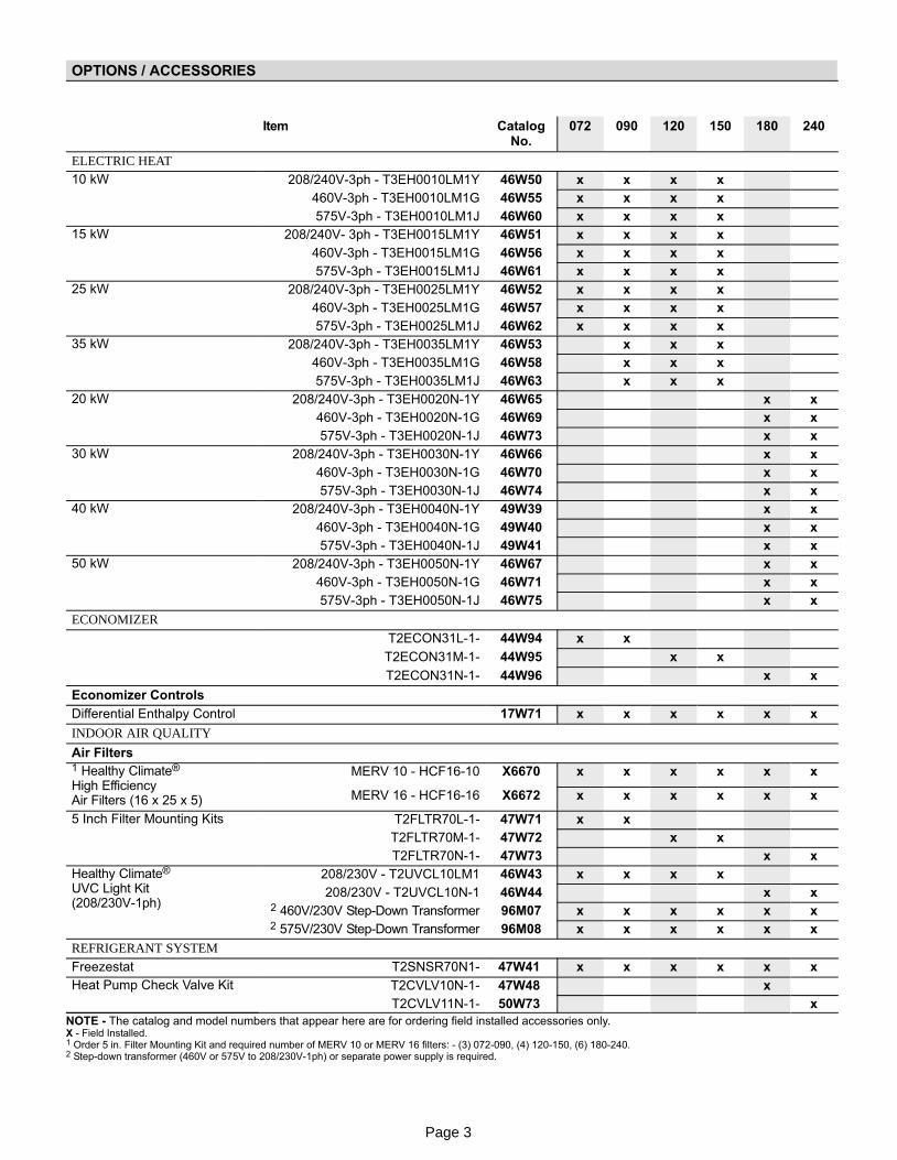
OPTIONS / ACCESSORIES
Item CatalogNo.
072 090 120 150 180 240
ELECTRIC HEAT
10 kW 208/240V−3ph − T3EH0010LM1Y 46W50 x x x x
460V−3ph − T3EH0010LM1G 46W55 x x x x
575V−3ph − T3EH0010LM1J 46W60 x x x x
15 kW 208/240V− 3ph − T3EH0015LM1Y 46W51 x x x x
460V−3ph − T3EH0015LM1G 46W56 x x x x
575V−3ph − T3EH0015LM1J 46W61 x x x x
25 kW 208/240V−3ph − T3EH0025LM1Y 46W52 x x x x
460V−3ph − T3EH0025LM1G 46W57 x x x x
575V−3ph − T3EH0025LM1J 46W62 x x x x
35 kW 208/240V−3ph − T3EH0035LM1Y 46W53 x x x
460V−3ph − T3EH0035LM1G 46W58 x x x
575V−3ph − T3EH0035LM1J 46W63 x x x
20 kW 208/240V−3ph − T3EH0020N−1Y 46W65 x x
460V−3ph − T3EH0020N−1G 46W69 x x
575V−3ph − T3EH0020N−1J 46W73 x x
30 kW 208/240V−3ph − T3EH0030N−1Y 46W66 x x
460V−3ph − T3EH0030N−1G 46W70 x x
575V−3ph − T3EH0030N−1J 46W74 x x
40 kW 208/240V−3ph − T3EH0040N−1Y 49W39 x x
460V−3ph − T3EH0040N−1G 49W40 x x
575V−3ph − T3EH0040N−1J 49W41 x x
50 kW 208/240V−3ph − T3EH0050N−1Y 46W67 x x
460V−3ph − T3EH0050N−1G 46W71 x x
575V−3ph − T3EH0050N−1J 46W75 x x
ECONOMIZER
T2ECON31L−1− 44W94 x x
T2ECON31M−1− 44W95 x x
T2ECON31N−1− 44W96 x x
Economizer Controls
Differential Enthalpy Control 17W71 x x x x x x
INDOOR AIR QUALITY
Air Filters1 Healthy Climate®
High EfficiencyAir Filters (16 x 25 x 5)
MERV 10 − HCF16−10 X6670 x x x x x x
MERV 16 − HCF16−16 X6672 x x x x x x
5 Inch Filter Mounting Kits T2FLTR70L−1− 47W71 x x
T2FLTR70M−1− 47W72 x x
T2FLTR70N−1− 47W73 x x
Healthy Climate® UVC Light Kit(208/230V−1ph)
208/230V − T2UVCL10LM1 46W43 x x x x
208/230V − T2UVCL10N−1 46W44 x x2 460V/230V Step−Down Transformer 96M07 x x x x x x2 575V/230V Step−Down Transformer 96M08 x x x x x x
REFRIGERANT SYSTEM
Freezestat T2SNSR70N1− 47W41 x x x x x x
Heat Pump Check Valve Kit T2CVLV10N−1− 47W48 x
T2CVLV11N−1− 50W73 x
NOTE − The catalog and model numbers that appear here are for ordering field installed accessories only.X − Field Installed.1 Order 5 in. Filter Mounting Kit and required number of MERV 10 or MERV 16 filters: − (3) 072−090, (4) 120−150, (6) 180−240.2 Step−down transformer (460V or 575V to 208/230V−1ph) or separate power supply is required.

Page 4
BLOWER DATA
TAA072 BLOWER PERFORMANCEAll data is measured external to the unit with dry coil and standard 2 in. air filters in place.
FOR ALL UNITS ADD:
1 − Wet indoor coil air resistance of selected unit.
2 − Any field installed accessories air resistance (electric heat, economizer, etc.) See page Page 11.
Then determine from table the blower motor hp and drive rpm required. See Page 10 for blower drive specifications.
AirVol-umecfm
STATIC PRESSURE EXTERNAL TO UNIT − Inches Water Gauge
0.1 0.2 0.3 0.4 0.5 0.6 0.7 0.8
RPM BHP RPM BHP RPM BHP RPM BHP RPM BHP RPM BHP RPM BHP RPM BHP
1900 428 0.57 479 0.66 531 0.74 581 0.81 629 0.88 675 0.94 718 1.01 758 1.07
2000 434 0.59 486 0.69 538 0.77 589 0.84 637 0.91 682 0.98 725 1.05 765 1.11
2100 441 0.62 493 0.72 545 0.8 596 0.88 644 0.95 689 1.02 732 1.09 771 1.15
2200 448 0.65 501 0.75 553 0.83 604 0.91 652 0.98 696 1.06 738 1.13 778 1.2
2300 456 0.68 508 0.78 561 0.86 612 0.94 659 1.02 704 1.1 746 1.17 785 1.24
2400 463 0.71 516 0.81 569 0.9 620 0.98 667 1.06 711 1.14 753 1.22 792 1.29
2500 470 0.74 524 0.84 578 0.94 629 1.02 675 1.1 719 1.19 760 1.27 798 1.34
2600 478 0.77 533 0.88 587 0.98 637 1.06 683 1.15 726 1.24 767 1.32 805 1.39
2700 486 0.81 542 0.92 596 1.02 646 1.11 692 1.2 734 1.29 775 1.37 812 1.45
2800 495 0.85 552 0.96 606 1.07 655 1.16 700 1.25 742 1.34 782 1.42 819 1.5
2900 504 0.89 561 1.01 616 1.11 665 1.2 708 1.3 750 1.39 789 1.48 826 1.56
3000 514 0.93 572 1.05 626 1.16 674 1.26 717 1.35 758 1.45 797 1.54 833 1.62
AirVolume
cfm
STATIC PRESSURE EXTERNAL TO UNIT − Inches Water Gauge
0.9 1 1.1 1.2 1.3 1.4 1.5
RPM BHP RPM BHP RPM BHP RPM BHP RPM BHP RPM BHP RPM BHP
1900 796 1.13 830 1.19 862 1.25 893 1.32 922 1.39 950 1.46 978 1.54
2000 802 1.17 836 1.23 868 1.3 898 1.37 928 1.44 956 1.52 983 1.6
2100 808 1.22 842 1.28 874 1.35 904 1.42 933 1.5 961 1.58 988 1.66
2200 814 1.26 848 1.33 879 1.4 909 1.48 938 1.56 966 1.64 993 1.73
2300 820 1.31 854 1.38 885 1.46 915 1.53 943 1.62 971 1.7 998 1.79
2400 827 1.36 860 1.43 891 1.51 920 1.59 949 1.68 976 1.77 1003 1.86
2500 833 1.41 866 1.49 897 1.57 926 1.66 954 1.75 981 1.84 1008 1.93
2600 840 1.47 872 1.55 902 1.63 932 1.72 960 1.81 987 1.91 1013 2.01
2700 846 1.53 878 1.61 908 1.7 937 1.79 965 1.88 992 1.98 1018 2.08
2800 853 1.58 884 1.67 914 1.76 943 1.86 970 1.96 997 2.06 1023 2.16
2900 859 1.65 890 1.74 920 1.83 948 1.93 975 2.03 1002 2.14 1028 2.24
3000 866 1.71 896 1.8 926 1.9 954 2 981 2.11 1007 2.22 1032 2.33

Page 5
TAA090 BLOWER PERFORMANCEAll data is measured external to the unit with dry coil and standard 2 in. air filters in place.
FOR ALL UNITS ADD:
1 − Wet indoor coil air resistance of selected unit.
2 − Any field installed accessories air resistance (electric heat, economizer, etc.) See page Page 11.
Then determine from table the blower motor hp and drive rpm required. See Page 10 for blower drive specifications.
AirVol-umecfm
STATIC PRESSURE EXTERNAL TO UNIT − Inches Water Gauge
0.1 0.2 0.3 0.4 0.5 0.6 0.7 0.8
RPM BHP RPM BHP RPM BHP RPM BHP RPM BHP RPM BHP RPM BHP RPM BHP
2400 508 0.79 565 0.89 619 0.98 667 1.06 710 1.14 750 1.23 787 1.3 822 1.38
2500 519 0.83 577 0.94 630 1.02 677 1.1 720 1.19 759 1.28 796 1.36 830 1.43
2600 531 0.87 588 0.98 641 1.07 688 1.16 729 1.25 769 1.34 805 1.42 839 1.49
2700 543 0.92 600 1.03 653 1.12 698 1.21 739 1.31 778 1.4 814 1.48 848 1.55
2800 555 0.97 613 1.08 664 1.17 709 1.27 749 1.37 788 1.46 824 1.54 857 1.62
2900 568 1.02 625 1.13 676 1.22 719 1.32 759 1.43 797 1.52 833 1.6 866 1.68
3000 581 1.07 638 1.18 687 1.28 730 1.39 769 1.49 807 1.58 842 1.67 875 1.75
3100 595 1.12 651 1.24 699 1.34 740 1.45 779 1.56 817 1.65 852 1.73 883 1.82
3200 609 1.18 664 1.3 710 1.41 751 1.52 789 1.63 827 1.72 861 1.8 892 1.89
3300 624 1.24 677 1.36 722 1.48 761 1.59 799 1.7 836 1.79 870 1.88 901 1.97
3400 639 1.3 690 1.43 733 1.55 772 1.67 810 1.77 846 1.86 879 1.95 909 2.05
3500 653 1.37 703 1.5 745 1.62 782 1.75 820 1.85 856 1.94 888 2.03 917 2.14
3600 668 1.44 715 1.57 756 1.7 793 1.83 830 1.93 865 2.02 897 2.12 925 2.24
AirVolume
cfm
STATIC PRESSURE EXTERNAL TO UNIT − Inches Water Gauge
0.9 1 1.1 1.2 1.3 1.4 1.5
RPM BHP RPM BHP RPM BHP RPM BHP RPM BHP RPM BHP RPM BHP
2400 855 1.44 888 1.51 920 1.59 950 1.67 979 1.77 1006 1.86 1033 1.96
2500 863 1.5 896 1.57 928 1.65 958 1.74 986 1.84 1013 1.94 1039 2.04
2600 872 1.56 904 1.64 936 1.72 965 1.82 993 1.92 1019 2.02 1045 2.12
2700 880 1.62 913 1.7 943 1.79 972 1.89 1000 2 1026 2.1 1052 2.2
2800 889 1.69 921 1.77 951 1.87 979 1.97 1006 2.08 1033 2.18 1058 2.29
2900 898 1.76 929 1.85 959 1.95 987 2.05 1013 2.16 1039 2.26 1064 2.37
3000 906 1.83 937 1.93 966 2.03 994 2.13 1020 2.24 1046 2.35 1070 2.46
3100 914 1.91 944 2.01 973 2.11 1001 2.22 1027 2.33 1052 2.44 1077 2.55
3200 922 1.99 952 2.09 980 2.2 1008 2.3 1033 2.41 1058 2.53 1083 2.64
3300 930 2.07 959 2.18 987 2.29 1014 2.39 1040 2.5 1065 2.62 1089 2.73
3400 938 2.16 966 2.27 994 2.38 1021 2.49 1046 2.6 1071 2.71 1095 2.83
3500 945 2.26 973 2.37 1001 2.48 1028 2.58 1053 2.69 1077 2.81 1101 2.93
3600 953 2.35 980 2.47 1008 2.58 1034 2.68 1059 2.79 1084 2.91 1107 3.03

Page 6
TAA120 BLOWER PERFORMANCEAll data is measured external to the unit with dry coil and standard 2 in. air filters in place.
FOR ALL UNITS ADD:
1 − Wet indoor coil air resistance of selected unit.
2 − Any field installed accessories air resistance (electric heat, economizer, etc.) See page Page 11.
Then determine from table the blower motor hp and drive rpm required. See Page 10 for blower drive specifications.
AirVolume
cfm
STATIC PRESSURE EXTERNAL TO UNIT − Inches Water Gauge
0.1 0.2 0.3 0.4 0.5 0.6 0.7 0.8
RPM BHP RPM BHP RPM BHP RPM BHP RPM BHP RPM BHP RPM BHP RPM BHP
3000 484 0.51 516 0.6 552 0.7 591 0.82 635 0.95 677 1.07 699 1.1 736 1.18
3200 499 0.62 531 0.7 566 0.8 606 0.92 651 1.06 684 1.15 707 1.18 746 1.28
3400 514 0.73 546 0.81 582 0.91 622 1.03 667 1.17 690 1.22 717 1.29 758 1.4
3600 529 0.84 562 0.93 598 1.03 639 1.15 679 1.28 697 1.31 730 1.4 772 1.52
3800 545 0.96 579 1.05 616 1.15 658 1.28 686 1.37 706 1.41 745 1.53 786 1.65
4000 562 1.09 596 1.18 634 1.29 674 1.41 693 1.46 720 1.54 761 1.67 802 1.79
4200 580 1.23 615 1.31 654 1.42 684 1.52 702 1.57 737 1.69 778 1.82 819 1.94
4400 600 1.37 635 1.45 672 1.56 691 1.62 717 1.72 756 1.86 796 1.98 836 2.09
4600 619 1.51 655 1.59 683 1.68 702 1.76 736 1.89 775 2.02 814 2.13 853 2.24
4800 639 1.65 673 1.73 692 1.81 719 1.93 757 2.08 795 2.19 832 2.3 871 2.4
5000 659 1.78 685 1.87 706 1.97 740 2.12 778 2.26 814 2.37 851 2.46 889 2.56
AirVolume
cfm
STATIC PRESSURE EXTERNAL TO UNIT − Inches Water Gauge
0.9 1 1.1 1.2 1.3 1.4 1.5
RPM BHP RPM BHP RPM BHP RPM BHP RPM BHP RPM BHP RPM BHP
3000 779 1.29 826 1.42 873 1.56 919 1.7 964 1.84 1009 1.98 1054 2.11
3200 790 1.4 836 1.53 882 1.66 929 1.8 974 1.94 1019 2.07 1063 2.21
3400 802 1.51 847 1.64 893 1.77 938 1.91 983 2.04 1028 2.17 1072 2.31
3600 815 1.64 859 1.76 904 1.89 949 2.03 993 2.16 1037 2.29 1080 2.42
3800 829 1.77 873 1.9 917 2.03 961 2.16 1005 2.29 1048 2.42 1090 2.55
4000 845 1.91 888 2.04 932 2.17 975 2.31 1018 2.43 1060 2.56 1102 2.69
4200 861 2.06 904 2.19 948 2.32 990 2.46 1033 2.59 1074 2.71 1116 2.84
4400 878 2.21 921 2.34 963 2.47 1006 2.6 1048 2.73 1089 2.86 1130 2.98
4600 894 2.36 936 2.49 979 2.61 1021 2.74 1063 2.87 1104 3 1145 3.12
4800 911 2.51 953 2.63 995 2.76 1036 2.88 1078 3.01 1119 3.13 1161 3.26
5000 928 2.67 969 2.78 1011 2.9 1052 3.03 1094 3.15 1135 3.27 1176 3.4

Page 7
TAA150 BLOWER PERFORMANCEAll data is measured external to the unit with dry coil and standard 2 in. air filters in place.
FOR ALL UNITS ADD:
1 − Wet indoor coil air resistance of selected unit.
2 − Any field installed accessories air resistance (electric heat, economizer, etc.) See page Page 11.
Then determine from table the blower motor hp and drive rpm required. See page Page 10 for blower drive specifications.
AirVolume
cfm
STATIC PRESSURE EXTERNAL TO UNIT − Inches Water Gauge
0.1 0.2 0.3 0.4 0.5 0.6 0.7 0.8
RPM BHP RPM BHP RPM BHP RPM BHP RPM BHP RPM BHP RPM BHP RPM BHP
4000 627 1.26 669 1.39 690 1.45 714 1.52 754 1.65 795 1.76 835 1.87 877 1.98
4200 653 1.42 684 1.52 701 1.57 736 1.69 777 1.82 816 1.92 856 2.02 897 2.13
4400 676 1.57 694 1.63 721 1.73 761 1.87 800 1.99 838 2.08 877 2.18 917 2.28
4600 688 1.7 710 1.79 747 1.93 787 2.06 823 2.16 860 2.24 898 2.33 938 2.43
4800 702 1.85 735 1.99 774 2.14 812 2.25 846 2.32 882 2.4 920 2.49 959 2.58
5000 725 2.06 763 2.21 801 2.34 837 2.44 869 2.49 903 2.55 941 2.64 979 2.73
5200 754 2.3 791 2.43 828 2.55 862 2.63 891 2.66 925 2.71 962 2.79 1000 2.88
5400 783 2.53 819 2.65 855 2.75 887 2.82 913 2.82 946 2.86 983 2.95 1021 3.03
5600 810 2.74 845 2.85 881 2.95 912 3.01 935 2.98 967 3.01 1004 3.1 1041 3.19
5800 835 2.95 871 3.05 906 3.15 936 3.19 957 3.14 987 3.16 1024 3.25 1062 3.34
6000 860 3.14 896 3.25 931 3.35 960 3.37 978 3.3 1008 3.31 1045 3.4 1083 3.48
AirVolume
cfm
STATIC PRESSURE EXTERNAL TO UNIT − Inches Water Gauge
0.9 1 1.1 1.2 1.3 1.4 1.5
RPM BHP RPM BHP RPM BHP RPM BHP RPM BHP RPM BHP RPM BHP
4000 920 2.1 963 2.22 1006 2.34 1048 2.46 1091 2.58 1133 2.69 1174 2.81
4200 939 2.24 982 2.36 1024 2.48 1067 2.59 1109 2.71 1151 2.83 1193 2.95
4400 959 2.39 1001 2.5 1043 2.61 1085 2.73 1127 2.85 1169 2.96 1211 3.08
4600 979 2.53 1020 2.64 1062 2.76 1104 2.87 1146 2.99 1188 3.1 1230 3.22
4800 999 2.68 1040 2.79 1082 2.9 1123 3.01 1165 3.12 1207 3.24 1248 3.35
5000 1019 2.83 1060 2.93 1101 3.04 1142 3.15 1184 3.26 1226 3.38 1267 3.49
5200 1040 2.98 1080 3.08 1121 3.19 1162 3.29 1203 3.41 1245 3.52 1286 3.63
5400 1060 3.13 1100 3.23 1140 3.33 1181 3.44 1222 3.55 1264 3.66 1305 3.77
5600 1080 3.28 1120 3.37 1160 3.48 1201 3.58 1242 3.69 1283 3.8 1324 3.91
5800 1101 3.43 1140 3.52 1180 3.62 1220 3.72 1261 3.83 1302 3.94 1343 4.05
6000 1121 3.57 1160 3.67 1200 3.77 1240 3.87 1280 3.97 1321 4.08 1362 4.19

Page 8
TAA180 BLOWER PERFORMANCEAll data is measured external to the unit with dry coil and standard 2 in. air filters in place.
FOR ALL UNITS ADD:
1 − Wet indoor coil air resistance of selected unit.
2 − Any field installed accessories air resistance (electric heat, economizer, etc.) See page Page 12.
Then determine from table the blower motor hp and drive rpm required. See page Page 10 for blower drive specifications.
AirVol-umecfm
STATIC PRESSURE EXTERNAL TO UNIT − Inches Water Gauge
0.1 0.2 0.3 0.4 0.5 0.6 0.7 0.8
RPM BHP RPM BHP RPM BHP RPM BHP RPM BHP RPM BHP RPM BHP RPM BHP
4800 440 0.78 486 1.16 534 1.46 582 1.7 628 1.9 670 2.07 709 2.18 744 2.24
5000 446 0.88 492 1.25 540 1.54 588 1.77 634 1.97 676 2.14 714 2.26 748 2.34
5200 452 0.98 499 1.34 547 1.62 595 1.84 640 2.04 682 2.22 719 2.34 753 2.43
5400 458 1.08 505 1.43 554 1.7 602 1.92 647 2.12 688 2.3 724 2.44 757 2.54
5600 465 1.18 512 1.52 561 1.77 609 1.99 653 2.2 694 2.39 729 2.53 762 2.65
5800 471 1.28 519 1.61 568 1.85 616 2.07 660 2.28 700 2.48 734 2.64 766 2.77
6000 478 1.38 526 1.7 575 1.93 623 2.15 667 2.37 706 2.58 740 2.76 771 2.91
6200 485 1.48 534 1.79 583 2.01 630 2.23 674 2.46 712 2.69 745 2.88 776 3.05
6400 493 1.59 542 1.88 591 2.1 638 2.32 681 2.56 718 2.81 750 3.01 780 3.2
6600 500 1.69 550 1.96 599 2.18 646 2.41 688 2.67 724 2.93 755 3.16 785 3.36
6800 508 1.79 558 2.05 607 2.27 654 2.51 695 2.78 730 3.07 761 3.32 789 3.54
7000 516 1.89 567 2.15 616 2.36 662 2.61 702 2.91 736 3.22 766 3.49 794 3.73
7200 525 1.99 575 2.24 625 2.46 670 2.73 709 3.05 742 3.38 771 3.68 798 3.94
AirVolume
cfm
STATIC PRESSURE EXTERNAL TO UNIT − Inches Water Gauge
0.9 1 1.1 1.2 1.3 1.4 1.5
RPM BHP RPM BHP RPM BHP RPM BHP RPM BHP RPM BHP RPM BHP
4800 778 2.33 811 2.47 844 2.69 876 2.94 907 3.18 936 3.38 966 3.58
5000 782 2.43 814 2.59 847 2.81 879 3.07 909 3.32 939 3.53 968 3.75
5200 786 2.54 818 2.71 850 2.95 881 3.22 912 3.48 941 3.7 970 3.93
5400 790 2.66 821 2.85 853 3.09 884 3.37 914 3.64 943 3.88 972 4.12
5600 794 2.79 825 2.99 856 3.24 887 3.54 917 3.82 946 4.07 975 4.33
5800 798 2.93 828 3.14 859 3.41 890 3.71 919 4.01 948 4.28 977 4.56
6000 801 3.07 832 3.3 862 3.58 892 3.9 922 4.22 951 4.51 980 4.81
6200 805 3.23 835 3.47 865 3.77 895 4.11 924 4.44 953 4.75 983 5.07
6400 809 3.4 839 3.65 868 3.97 898 4.32 927 4.68 956 5.01 986 5.35
6600 813 3.58 842 3.85 872 4.18 901 4.56 930 4.93 959 5.28 989 5.65
6800 817 3.77 846 4.06 875 4.41 904 4.8 933 5.2 962 5.58 993 5.97
7000 821 3.98 849 4.29 878 4.66 907 5.07 936 5.49 965 5.89 996 6.31
7200 825 4.21 853 4.53 881 4.92 910 5.35 939 5.79 969 6.22 1000 6.67

Page 9
TAA240 BLOWER PERFORMANCEAll data is measured external to the unit with dry coil and standard 2 in. air filters in place.
FOR ALL UNITS ADD:
1 − Wet indoor coil air resistance of selected unit.
2 − Any field installed accessories air resistance (electric heat, economizer, etc.) See page Page 12.
Then determine from table the blower motor hp and drive rpm required. See page Page 10 for blower drive specifications.
AirVol-umecfm
STATIC PRESSURE EXTERNAL TO UNIT − Inches Water Gauge
0.1 0.2 0.3 0.4 0.5 0.6 0.7 0.8
RPM BHP RPM BHP RPM BHP RPM BHP RPM BHP RPM BHP RPM BHP RPM BHP
6400 535 1.84 583 2.06 630 2.28 674 2.51 713 2.77 746 3.03 776 3.25 805 3.44
6600 545 1.94 593 2.16 640 2.38 683 2.63 720 2.91 753 3.19 782 3.43 810 3.64
6800 555 2.05 604 2.27 650 2.5 692 2.76 728 3.06 759 3.36 787 3.62 815 3.85
7000 566 2.16 614 2.38 660 2.62 701 2.9 736 3.23 766 3.55 793 3.83 820 4.08
7200 577 2.27 625 2.49 671 2.75 710 3.05 743 3.4 772 3.75 799 4.05 825 4.32
7400 588 2.38 637 2.61 681 2.88 719 3.21 751 3.59 778 3.96 804 4.29 829 4.58
7600 600 2.49 648 2.74 691 3.03 727 3.39 758 3.79 784 4.18 809 4.54 834 4.85
7800 613 2.61 660 2.88 701 3.19 735 3.57 764 4 790 4.42 814 4.8 839 5.14
8000 626 2.73 671 3.02 711 3.36 743 3.77 771 4.22 796 4.67 819 5.08 844 5.45
8200 638 2.86 682 3.18 720 3.55 751 3.98 777 4.46 801 4.93 824 5.37 849 5.77
8400 651 3 694 3.35 729 3.75 758 4.21 784 4.7 807 5.21 829 5.68 853 6.12
8600 664 3.15 704 3.53 738 3.96 765 4.44 789 4.97 812 5.5 834 6 858 6.48
8800 676 3.32 714 3.73 746 4.19 772 4.7 795 5.25 817 5.81 839 6.35 863 6.86
9000 688 3.5 724 3.94 754 4.43 778 4.97 800 5.54 822 6.13 844 6.71 868 7.27
9200 700 3.71 733 4.17 761 4.69 784 5.26 806 5.86 826 6.48 848 7.09 873 7.69
9400 711 3.93 742 4.43 768 4.97 790 5.57 811 6.19 831 6.85 853 7.5 878 8.15
9600 721 4.17 750 4.71 775 5.28 796 5.9 816 6.56 836 7.25 858 7.94 884 8.63
AirVolume
cfm
STATIC PRESSURE EXTERNAL TO UNIT − Inches Water Gauge
0.9 1 1.1 1.2 1.3 1.4 1.5
RPM BHP RPM BHP RPM BHP RPM BHP RPM BHP RPM BHP RPM BHP
6400 833 3.66 863 3.92 892 4.24 922 4.59 952 4.93 981 5.28 1012 5.65
6600 838 3.87 867 4.15 896 4.49 926 4.86 956 5.22 986 5.6 1017 5.99
6800 842 4.09 871 4.39 900 4.75 930 5.14 960 5.54 991 5.94 1022 6.36
7000 847 4.34 875 4.65 905 5.03 934 5.45 964 5.87 996 6.3 1028 6.75
7200 851 4.6 880 4.94 909 5.34 939 5.78 969 6.22 1001 6.68 1034 7.16
7400 856 4.88 884 5.24 913 5.66 943 6.13 974 6.6 1006 7.09 1040 7.6
7600 861 5.18 888 5.56 918 6.01 948 6.5 980 7.01 1012 7.53 1047 8.07
7800 865 5.49 893 5.9 923 6.38 953 6.9 985 7.44 1019 7.99 1054 8.56
8000 870 5.83 898 6.27 928 6.77 959 7.32 991 7.89 1026 8.48 1062 9.08
8200 875 6.19 903 6.65 933 7.19 964 7.77 998 8.37 1033 9 1070 9.63
8400 879 6.56 908 7.07 938 7.63 970 8.25 1004 8.89 1040 9.54 1078 10.2
8600 884 6.96 913 7.5 944 8.1 977 8.75 1011 9.43 1048 10.12 1087 10.81
8800 890 7.39 919 7.96 950 8.6 983 9.29 1019 10 1057 10.73 1096 11.44
9000 895 7.83 924 8.45 956 9.13 991 9.85 1027 10.6 1066 11.36 1105 12.11
9200 900 8.31 931 8.97 963 9.69 998 10.45 1036 11.24 1075 12.03 1115 12.8
9400 906 8.81 937 9.51 970 10.28 1006 11.08 1045 11.91 1085 12.73 1125 13.52
9600 912 9.34 944 10.09 978 10.9 1015 11.75 1054 12.61 1095 13.46 1136 14.28

Page 10
BLOWER DRIVE SPECIFICATIONS
Static RPM RangeMotor HP
072 090 120 150 180 240Nominal Maximum
Low 552 − 782 1.5 1.72 � − − − − − − − − − − − − − − −
Standard 690 − 936 1.5 1.72 S − − − − − − − − − − − − − − −
High 906 − 1121 2 2.3 � − − − − − − − − − − − − − − −
Low 644 − 874 2 2.3 − − − � − − − − − − − − − − − −
Standard 782 − 1012 2 2.3 − − − S − − − − − − − − − − − −
High 966 − 1196 3 3.45 − − − � − − − − − − − − − − − −
Low 690 − 893 2 2.3 − − − − − − � − − − − − − − − −
Standard 852 − 1055 2 2.3 − − − − − − S − − − − − − − − −
High 986 − 1232 3 3.45 − − − − − − � − − − − − − − − −
Low 782 − 1012 3 3.45 − − − − − − − − − � − − − − − −
Standard 920 − 1150 3 3.45 − − − − − − − − − S − − − − − −
High 1134 − 1380 5 5.75 − − − − − − − − − � − − − − − −
Low 591 − 838 3 3.45 − − − − − − − − − − − − � − − −
Standard 782 − 1012 5 5.75 − − − − − − − − − − − − S − − −
High 920 − 1150 5 5.75 − − − − − − − − − − − − � − − −
Low 679 − 863 5 5.75 − − − − − − − − − − − − − − − �
Standard 808 − 1026 7.5 8.63 − − − − − − − − − − − − − − − S
High 1002 − 1282 7.5 8.63 − − − − − − − − − − − − − − − �
NOTE − Using total air volume and system static pressure requirements, determine from blower performance tables rpm and motor horsepower required.Maximum usable horsepower of motors are shown. In Canada, nominal motor horsepower is also maximum usable motor horsepower. If motors ofcomparable horsepower are used, be sure to keep within the service factor limitations outlined on the motor nameplate.S − Factory installed standard
� − Factory Installed with extended lead time.
BLOWER MOTOR ELECTRICAL DATA
Model No. 072 090 120 150 180 240
1.5 HPBlowerMotor
Maximum OvercurrentProtection / MinimumCircuit Ampacity
208/230/−60hz−3ph 15 / 8 − − − − − − − − − − − − − − −
460V−60hz−3ph 15 / 4 − − − − − − − − − − − − − − −
575V−60hz−3ph 15 / 3 − − − − − − − − − − − − − − −
2 HPBlowerMotor
Maximum OvercurrentProtection / MinimumCircuit Ampacity
208/230/−60hz−3ph 15 / 10 15 / 10 15 / 10 − − − − − − − − −
460V−60hz−3ph 15 / 5 15 / 5 15 / 5 − − − − − − − − −
575V−60hz−3ph 15 / 4 15 / 4 15 / 4 − − − − − − − − −
3 HPBlowerMotor
Maximum OvercurrentProtection / MinimumCircuit Ampacity
208/230/−60hz−3ph − − − 20 / 14 20 / 14 20 / 14 20 / 14 − − −
460V−60hz−3ph − − − 15 / 6 15 / 6 15 / 6 15 / 6 − − −
575V−60hz−3ph − − − 15 / 5 15 / 5 15 / 5 15 / 5 − − −
5 HPBlowerMotor
Maximum OvercurrentProtection / MinimumCircuit Ampacity
208/230/−60hz−3ph − − − − − − − − − 35 / 21 35 / 21 35 / 21
460V−60hz−3ph − − − − − − − − − 15 / 10 15 / 10 15 / 10
575V−60hz−3ph − − − − − − − − − 15 / 8 15 / 8 15 / 8
7.5 HPBlowerMotor
Maximum OvercurrentProtection / MinimumCircuit Ampacity
208/230/−60hz−3ph − − − − − − − − − − − − − − − 50 / 31
460V−60hz−3ph − − − − − − − − − − − − − − − 20 / 14
575V−60hz−3ph − − − − − − − − − − − − − − − 20 / 12
Page 11
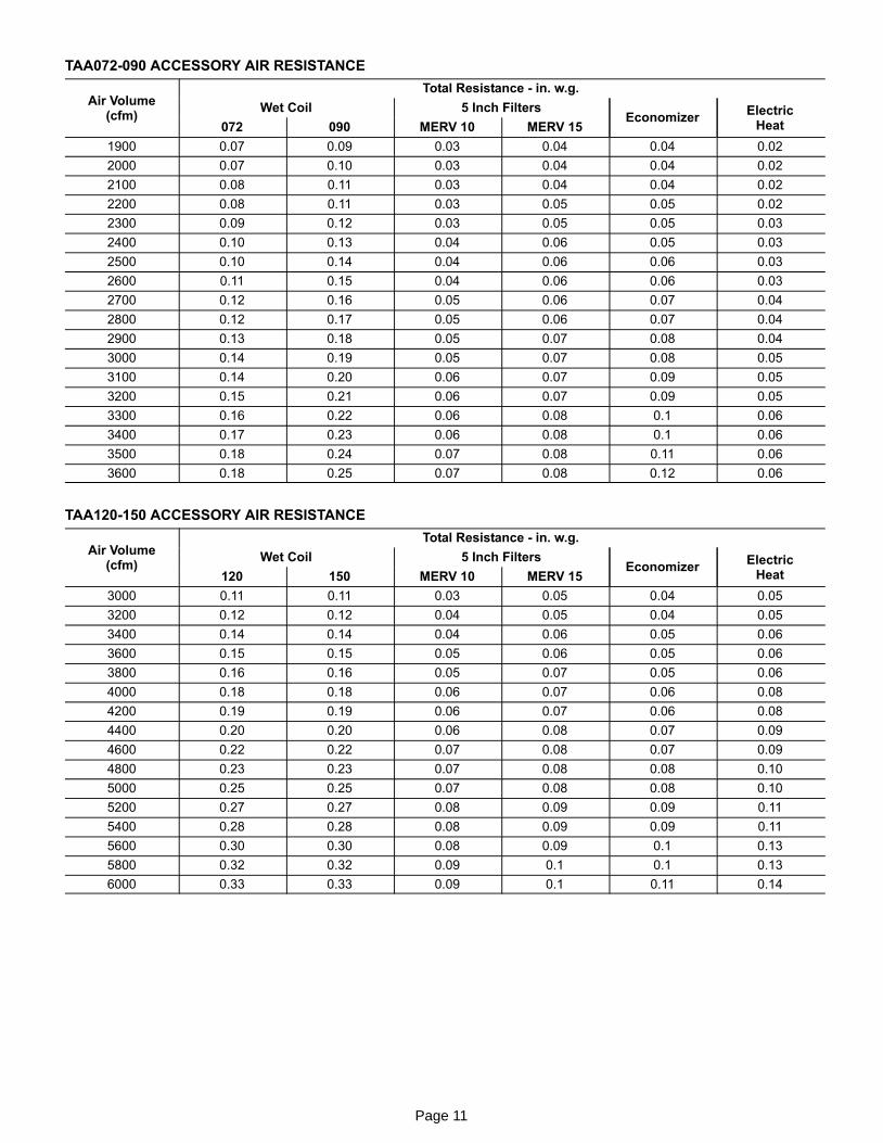
TAA072−090 ACCESSORY AIR RESISTANCE
Air Volume(cfm)
Total Resistance − in. w.g.
Wet Coil 5 Inch FiltersEconomizer
ElectricHeat072 090 MERV 10 MERV 15
1900 0.07 0.09 0.03 0.04 0.04 0.02
2000 0.07 0.10 0.03 0.04 0.04 0.02
2100 0.08 0.11 0.03 0.04 0.04 0.02
2200 0.08 0.11 0.03 0.05 0.05 0.02
2300 0.09 0.12 0.03 0.05 0.05 0.03
2400 0.10 0.13 0.04 0.06 0.05 0.03
2500 0.10 0.14 0.04 0.06 0.06 0.03
2600 0.11 0.15 0.04 0.06 0.06 0.03
2700 0.12 0.16 0.05 0.06 0.07 0.04
2800 0.12 0.17 0.05 0.06 0.07 0.04
2900 0.13 0.18 0.05 0.07 0.08 0.04
3000 0.14 0.19 0.05 0.07 0.08 0.05
3100 0.14 0.20 0.06 0.07 0.09 0.05
3200 0.15 0.21 0.06 0.07 0.09 0.05
3300 0.16 0.22 0.06 0.08 0.1 0.06
3400 0.17 0.23 0.06 0.08 0.1 0.06
3500 0.18 0.24 0.07 0.08 0.11 0.06
3600 0.18 0.25 0.07 0.08 0.12 0.06
TAA120−150 ACCESSORY AIR RESISTANCE
Air Volume(cfm)
Total Resistance − in. w.g.
Wet Coil 5 Inch FiltersEconomizer
ElectricHeat120 150 MERV 10 MERV 15
3000 0.11 0.11 0.03 0.05 0.04 0.05
3200 0.12 0.12 0.04 0.05 0.04 0.05
3400 0.14 0.14 0.04 0.06 0.05 0.06
3600 0.15 0.15 0.05 0.06 0.05 0.06
3800 0.16 0.16 0.05 0.07 0.05 0.06
4000 0.18 0.18 0.06 0.07 0.06 0.08
4200 0.19 0.19 0.06 0.07 0.06 0.08
4400 0.20 0.20 0.06 0.08 0.07 0.09
4600 0.22 0.22 0.07 0.08 0.07 0.09
4800 0.23 0.23 0.07 0.08 0.08 0.10
5000 0.25 0.25 0.07 0.08 0.08 0.10
5200 0.27 0.27 0.08 0.09 0.09 0.11
5400 0.28 0.28 0.08 0.09 0.09 0.11
5600 0.30 0.30 0.08 0.09 0.1 0.13
5800 0.32 0.32 0.09 0.1 0.1 0.13
6000 0.33 0.33 0.09 0.1 0.11 0.14

Page 12
TAA180−240 ACCESSORY AIR RESISTANCE
Air Volume(cfm)
Total Resistance − in. w.g.
Wet Coil 5 Inch FiltersEconomizer
ElectricHeat180 240 MERV 10 MERV 15
4500 0.08 0.11 0.03 0.05 0.05 0.06
4750 0.09 0.12 0.04 0.05 0.06 0.08
5000 0.10 0.13 0.04 0.06 0.07 0.09
5250 0.11 0.14 0.04 0.06 0.07 0.09
5500 0.11 0.15 0.05 0.06 0.08 0.11
5750 0.12 0.16 0.05 0.06 0.08 0.11
6000 0.13 0.18 0.05 0.07 0.10 0.12
6250 0.14 0.19 0.06 0.07 0.11 0.14
6500 0.15 0.20 0.06 0.07 0.11 0.14
6750 0.16 0.21 0.06 0.08 0.12 0.15
7000 0.17 0.22 0.07 0.08 0.12 0.15
7250 0.18 0.24 0.07 0.08 0.13 0.17
7500 0.19 0.25 0.07 0.08 0.13 0.17
7750 0.19 0.26 0.08 0.09 0.14 0.18
8000 0.21 0.28 0.08 0.09 0.16 0.20
8250 0.22 0.29 0.08 0.09 0.16 0.20
8500 0.23 0.31 0.09 0.1 0.17 0.21
8750 0.24 0.32 0.09 0.1 0.17 0.21
9000 0.25 0.33 0.09 0.1 0.18 0.23
9250 0.26 0.35 0.10 0.11 0.19 0.24
9500 0.27 0.36 0.10 0.11 0.20 0.26
9750 0.28 0.38 0.10 0.11 0.22 0.27
10,000 0.29 0.40 0.11 0.12 0.23 0.29
TAA072 OPTIONAL ELECTRIC HEAT DATA
Electric HeatSize
No.of
Steps
VoltsInput
kWInput
1 BtuhOutput
2 Total Unit + Electric HeatMinimum Circuit
Ampacity
Total Unit + Electric HeatMaximum Overcurrent
Protection
1.5 hp 2 hp 1.5 hp 2 hp
10 kW 1 208 7.5 25,600 34 36 35 40
1220 8.4 28,700
38 40 40 40230 9.2 31,400240 10 34,100
1440 8.4 28,700
19 20 20 20460 9.2 31,400480 10 34,100
1550 8.4 28,700
15 16 15 20575 9.2 31,400600 10 34,100
15 kW 1 208 11.3 38400 47 49 50 50
1220 12.6 43,000
53 55 60 60230 13.5 47,000240 15 51,200
1440 12.6 43,000
27 27 30 30460 13.5 47,,000480 15 51,200
1550 12.6 43,000
21 22 25 25575 13.5 47,000600 15 51,200
25 kW 3 2 208 18.8 64,100 73 75 80 80
3 2220 21 71,700
83 85 90 90230 23 78,300240 25 85,300
1440 21 71,700
42 42 45 45460 23 78,300480 25 85,300
1550 21 71,700
34 34 35 35575 23 78,300600 25 85,300
1 Electric heater capacity only − does not include additional blower motor heat capacity.2 Refer to National or Canadian Electrical Code manual to determine wire, fuse and disconnect size requirements. Use wires suitable for at least 167°F.3 May be used with two stage control (field provided).

Page 13
TAA090 OPTIONAL ELECTRIC HEAT DATA
Electric HeatSize
No.of
Steps
VoltsInput
kWInput
1 BtuhOutput
2 Total Unit + Electric HeatMinimum Circuit
Ampacity
Total Unit + Electric HeatMaximum Overcurrent
Protection
2 hp 3 hp 2 hp 3 hp
10 kW 1 208 7.5 25,600 36 40 40 40
220 8.4 28,700
1 230 9.2 31,400 40 44 40 45
240 10 34,100
440 8.4 28,700
1 460 9.2 31,400 20 21 20 25
480 10 34,100
550 8.4 28,700
1 575 9.2 31,400 16 17 20 20
600 10 34,100
15 kW 1 208 11.3 38400 49 53 50 60
220 12.6 43,000
1 230 13.5 47,000 55 59 60 60
240 15 51,200
440 12.6 43,000
1 460 13.5 47,,000 27 29 30 30
480 15 51,200
550 12.6 43,000
1 575 13.5 47,000 22 23 25 25
600 15 51,200
25 kW 3 2 208 18.8 64,100 75 79 80 80
220 21 71,7003 2 230 23 78,300 85 89 90 90
240 25 85,300
440 21 71,700
1 460 23 78,300 42 44 45 45
480 25 85,300
550 21 71,700
1 575 23 78,300 34 35 35 35
600 25 85,300
33.3 kW 3 2 208 25 85,300 97 100 100 100
220 28 95,5003 2 230 30.6 104,400 110 114 110 125
240 33.3 113,700
440 28 95,500
1 460 30.6 104,400 55 57 60 60
480 33.3 113,700
550 28 95,500
1 575 30.6 104,400 44 45 45 45
600 33.3 113,7001 Electric heater capacity only − does not include additional blower motor heat capacity.2 Refer to National or Canadian Electrical Code manual to determine wire, fuse and disconnect size requirements. Use wires suitable for at least 167°F.3 May be used with two stage control (field provided).

Page 14
TAA120 OPTIONAL ELECTRIC HEAT DATA
Electric HeatSize
No.of
Steps
VoltsInput
kWInput
1 BtuhOutput
2 Total Unit + Electric HeatMinimum Circuit
Ampacity
Total Unit + Electric HeatMaximum Overcurrent
Protection
2 hp 3 hp 2 hp 3 hp
10 kW 1 208 7.5 25,600 36 40 40 40
220 8.4 28,700
1 230 9.2 31,400 40 44 40 45
240 10 34,100
440 8.4 28,700
1 460 9.2 31,400 20 21 20 25
480 10 34,100
550 8.4 28,700
1 575 9.2 31,400 16 17 20 20
600 10 34,100
15 kW 1 208 11.3 38400 49 53 50 60
220 12.6 43,000
1 230 13.5 47,000 55 59 60 60
240 15 51,200
440 12.6 43,000
1 460 13.5 47,,000 27 29 30 30
480 15 51,200
550 12.6 43,000
1 575 13.5 47,000 22 23 25 25
600 15 51,200
25 kW 3 2 208 18.8 64,100 75 79 80 80
220 21 71,7003 2 230 23 78,300 85 89 90 90
240 25 85,300
440 21 71,700
1 460 23 78,300 42 44 45 45
480 25 85,300
550 21 71,700
1 575 23 78,300 34 35 35 35
600 25 85,300
33.3 kW 3 2 208 25 85,300 97 100 100 100
220 28 95,5003 2 230 30.6 104,400 110 114 110 125
240 33.3 113,700
440 28 95,500
1 460 30.6 104,400 55 57 60 60
480 33.3 113,700
550 28 95,500
1 575 30.6 104,400 44 45 45 45
600 33.3 113,7001 Electric heater capacity only − does not include additional blower motor heat capacity.2 Refer to National or Canadian Electrical Code manual to determine wire, fuse and disconnect size requirements. Use wires suitable for at least 167°F.3 May be used with two stage control (field provided).

Page 15
TAA150 OPTIONAL ELECTRIC HEAT DATA
Electric HeatSize
No.of
Steps
VoltsInput
kWInput
1 BtuhOutput
2 Total Unit + Electric HeatMinimum Circuit
Ampacity
Total Unit + Electric HeatMaximum Overcurrent
Protection
3 hp 5 hp 3 hp 5 hp
10 kW 1 208 7.5 25,600 40 47 40 50
220 8.4 28,700
1 230 9.2 31,400 44 51 45 60
240 10 34,100
440 8.4 28,700
1 460 9.2 31,400 21 25 25 25
480 10 34,100
550 8.4 28,700
1 575 9.2 31,400 17 20 20 20
600 10 34,100
15 kW 1 208 11.3 38400 53 60 60 60
220 12.6 43,000
1 230 13.5 47,000 59 66 60 70
240 15 51,200
440 12.6 43,000
1 460 13.5 47,,000 29 32 30 35
480 15 51,200
550 12.6 43,000
1 575 13.5 47,000 23 26 25 30
600 15 51,200
25 kW 3 2 208 18.8 64,100 79 86 80 90
220 21 71,7003 2 230 23 78,300 89 96 90 100
240 25 85,300
440 21 71,700
1 460 23 78,300 44 48 45 50
480 25 85,300
550 21 71,700
1 575 23 78,300 35 38 35 40
600 25 85,300
33.3 kW 3 2 208 25 85,300 100 108 100 110
220 28 95,5003 2 230 30.6 104,400 114 121 125 125
240 33.3 113,700
440 28 95,500
1 460 30.6 104,400 57 60 60 60
480 33.3 113,700
550 28 95,500
1 575 30.6 104,400 45 48 45 50
600 33.3 113,7001 Electric heater capacity only − does not include additional blower motor heat capacity.2 Refer to National or Canadian Electrical Code manual to determine wire, fuse and disconnect size requirements. Use wires suitable for at least 167°F.3 May be used with two stage control (field provided).

Page 16
TAA180 OPTIONAL ELECTRIC HEAT DATA
Electric HeatSize
No.of
Steps
VoltsInput
kWInput
1 BtuhOutput
2 Total Unit + Electric HeatMinimum Circuit
Ampacity
Total Unit + Electric HeatMaximum Overcurrent
Protection
3 hp 5 hp 3 hp 5 hp
20 kW 1 208 14.8 50,600 65 73 70 80
220 16.5 56,500
1 230 18.1 61,800 73 81 80 90
240 19.7 67,300
440 16.8 57,500
1 460 18.4 62,900 37 40 40 40
480 20 68,300
550 16.8 57,300
1 575 18.4 62,600 29 32 30 35
600 20 68,300
30 kW 2 208 22.5 76,900 92 99 100 100
220 25.2 86,100
2 230 27.5 94,100 104 112 110 125
240 30 102,500
440 25.2 86,100
1 460 27.5 94,100 52 55 60 60
480 30 102,500
550 25.2 86,200
1 575 27.5 94,200 41 44 45 45
600 30 102,500
40 kW 2 208 29.3 100,000 115 123 125 125
220 32.8 112,000
2 230 35.8 122,300 131 139 150 150
240 39 133,200
440 32.8 112,000
1 460 35.9 122,400 65 69 70 70
480 39 133,200
550 33.6 114,800
1 575 36.7 125,500 53 56 60 60
600 40 136,600
50 kW 2 208 36.1 123,200 114 121 125 125
220 40.3 137,700
2 230 44.1 150,600 129 137 150 150
240 48 163,900
440 42 143,400
2 460 45.9 156,700 74 81 80 90
480 50 170,800
550 42 143,500
2 575 45.9 156,800 62 69 70 70
600 50 170,8001 Electric heater capacity only − does not include additional blower motor heat capacity.2 Refer to National or Canadian Electrical Code manual to determine wire, fuse and disconnect size requirements. Use wires suitable for at least 167°F.3 May be used with two stage control (field provided).

Page 17
TAA240 OPTIONAL ELECTRIC HEAT DATA
Electric HeatSize
No.of
Steps
VoltsInput
kWInput
1 BtuhOutput
2 Total Unit + Electric HeatMinimum Circuit
Ampacity
Total Unit + Electric HeatMaximum Overcurrent
Protection
5 hp 7.5 hp 5 hp 7.5 hp
20 kW 1 208 14.8 50,600 73 82 80 90
220 16.5 56,500
1 230 18.1 61,800 81 90 90 90
240 19.7 67,300
440 16.8 57,500
1 460 18.4 62,900 40 44 40 45
480 20 68,300
550 16.7 57,300
1 575 18.4 62,600 32 36 35 40
600 20 68,300
30 kW 2 208 22.5 76,900 99 109 100 110
220 25.2 86,100
2 230 27.6 94,100 112 121 125 125
240 30 102,500
440 25.2 86,100
1 460 27.6 94,100 55 59 60 60
480 30 102,500
550 25.2 86,100
1 575 27.6 94,200 44 48 45 50
600 30 102,500
40 kW 2 208 29.3 100,000 123 132 125 150
220 32.8 112,000
2 230 35.8 122,300 139 148 150 150
240 39 133,200
440 32.8 112,000
1 460 35.9 122,400 69 73 70 80
480 39 133,200
550 33.6 114,800
1 575 36.7 125,500 56 60 60 60
600 40 136,600
50 kW 2 208 36.1 123,200 121 131 125 150
220 40.3 137,700
2 230 44.1 150,600 137 146 150 150
240 48 163,900
440 42 143,400
2 460 45.9 156,700 81 91 90 100
480 50 170,800
550 42 143,500
2 575 45.9 156,800 69 79 70 80
600 50 170,8001 Electric heater capacity only − does not include additional blower motor heat capacity.2 Refer to National or Canadian Electrical Code manual to determine wire, fuse and disconnect size requirements. Use wires suitable for at least 167°F.3 May be used with two stage control (field provided).

Page 18
I − UNIT COMPONENTS
A − Blower Contactor K3
K3 is a three−pole contactor used to control the blower. On
a call for heat (see economizer relay K43), cool or continu-
ous blower K3−1 contacts close energizing the indoor blow-
er B3. See wiring diagram.
B − Economizer Relay K43
Relay K43 is a single−pole double throw relay used to con-
trol the economizer. When there is a call for cooling, K43−1
contacts close energizing the economizer and blower con-
tactor K3. See wiring diagram.
C − Blower Motor B3
See Page 10 for blower drive specifications and blower motor
electrical data.
D − Blower Motor Overload Relay S42
Relay S42 is used for �M� voltage and units with high effi-
ciency motors only. S42 is connected in line with the blower
motor to monitor the current flow to the motor. When the
relay senses an overload condition, a set of N.C. contacts
open to de−energize all 24 volt circuits.
E − Terminal Block TB1
All field wring connections are made at terminal block TB1.
F − Condensate Pan and Over Flow Relay K220 &
Switch S149
A reversible drain pan is provided. Never connect conden-
sate drain to a closed system. Condensate drain line must
have a trap in the line at the unit exit. K220 and S149 are
field installed and used to prevent condensate overflow. In
the event of a blocked drain plug and condensate begins
rise, N.O. S149 will close energizing relay K220. N.C. K220
opens de−energizing the the TAA unit.
FIGURE 1
CONTACTOR(K3−1)
GROUNDLUG
TERMINAL STRIP(TB1)
BLOWERRELAY (K43)
THREE−PHASETHERMAL OVERLOAD
RELAY (S42)(M VOLTAGE)
TAA CONTROL BOX
FIGURE 2
Coil
Expansion ValveBlowerControl Box
TAA072/090/120/150
FIGURE 3
CoilExpansion ValveBlowerControl Box
TAA180/240
II − REFRIGERATION SYSTEM
Units are equipped with single refrigerant circuit (072) or
dual refrigerant circuit (090−240). The 090−240 units
have a dual distribution system for two stage capacity
control during cooling cycles. Each circuit has its own
service valve connection and expansion valve.

Page 19
III − BLOWER SPEED & BELT TENSION
Air Volume Adjustment
FIXED PULLEY
BLOWER BELT
ADJUSTABLEPULLEY
ADJUSTABLE PULLEY
ALLEN SCREW
Run the blower without a cooling demand.
Use the static pressure and rev/min readings todetermine the unit’s air volume (see applicable blowerperformance tables).
Measure the indoor blower motor’s rpm.
Measure the static pressure external to the unit.
NOTE − The indoor coil must be dry and the airfilters must be in place when the followingmeasurements are taken.
Loosen the Allen screw on the adjustable pulley.
Turn the adjustable sheave clockwise to increase the airvolume or counterclockwise to decrease the air volume.
Once the desired air volume has been achieved, tightenthe Allen screw.
1
2
3
4
5
6
7
FIGURE 4
Adjusting Belt Tension
Place belt over all three pulleys.
Using a 15/16" wrench on thetensioner body nut, apply force untilmarks align as shown.
While holding the tensioner in thisposition, tighten the mounting bolt to 23ft−lbs using a 9/16" wrench.
1
2
3
BELT TENSIONER
FIGURE 5

Page 20
IV − Electric Heat Components
See electric heat tables (table of contents) for electric heat
matchups. EHA units consists of electric heating elements
exposed to the airstream. Multiple−stage elements are se-
quenced on and off by time delays in response to thermo-
stat demand.
1 − Heating Elements HE1, HE2, HE3 & HE4
Heating elements are composed of helix wound bare
nichrome exposed directly to the airstream. Heating
elements are energized directly by contactors. Once
energized, heat transfer is instantaneous. Overtemper-
ature protection is provided by primary and secondary
high temperature limits. Overcurrent protection is pro-
vided by fuses. Each stage of electric heat consists of
three elements connected in a three-phase arrange-
ment. Elements in 208/230V units are connected in a
�Delta" arrangement. Elements in 460 and 575V units
are connected in �Wye" arrangement. Each stage is en-
ergized independently by a three-pole double-break con-
tactor and is protected by safety limits.
2 − Contactors K15 & K16
Contactors K15 and K16 are three−pole double break re-
lays with a 24 volt coil that energize their respective heating
elements on thermostat demand. K15 energizes first stage
heat elements and K16 energizes second stage elements.
3 − Electric Heat Sequencer Relays K32
Relay K32 is a N.O. sequencer relay with a resistive ele-
ment for a coil and a bi-metal disk which actuates the
contacts. The relays are located on the electric heat vestibule
panel and are energized by a 24V heating demand (W1, W2).
When energized, the internal resistance heats the bi-metal
disk causing the contacts to close. When the relay is de-ener-
gized, the disk cools and the contacts open. The relay
energizes different stages of heat.
4 − Relays K9 and K19
Relays K9 and K19 are used to electrically isolate the TAA
24 volts components from the T3EHA 24 volt components.
The coil on the relays are connected to first stage and sec-
ond stage heat. On a first stage heat demand K9 is ener-
gized. K9−1 closes energizing first stage heat contactor
K15. On a second stage heat call K19 is energized. When
K19−1 closes contactor K16 is energized which energizes
relay K32.
5 − Fuse F3
Heating elements in all T3EHA units are protected by fuse
F3. The fuse is connected in series with each leg of electric
heat.
6 − Fuse F4
F4 serves the same purpose as F3 but is in line with line volt-
age and protects the indoor blower B3.
7 − Transformer T2
T2 is line voltage to 24VAC which provides 24VAC to power
to all T3EHA contactor coils, relays and timers.
8 − High Temperature Limit S15 (Primary)
S15 is the primary high temperature limit. It is located in
the electric heat unit immediately downstream from the
heating elements. S15 is a single-pole single-throw nor-
mally closed thermostat wired in series with the first stage
contactor coil.
When S15 opens, indicating a problem in the system, contac-
tor K15 is de-energized. When K15 is de-energized, first stage
and all subsequent stages of heat are de-energized. Since the
indoor blower is controlled by demand (K9 remains ener-
gized), the indoor blower continues operating.
9 − High Temperature Limit S20 (Secondary)
Each heating element assembly is electrically connected to
two high temperature limits S20 (refer to wiring diagrams in
back of this manual). Each limit is connected in series with one
leg of the three-phase element assembly. The third leg of each
assembly is not equipped with a limit. Three-phase operating
characteristics allow one of the other two limits to protect the
third leg.

Page 21
V − Wiring Diagrams
TAA072/240 − SEQUENCE OF OPERATION
1. W1 heat demand energizes the economizer relay K43.
2. When K43−1 closes blower relay K3 is energized.
3. K3−1 closes energizing indoor blower B3.

Page 22
T3EH 072/150, 10−15 kW Y Voltage − Sequence of Operation
Heat Call TSA / TPA
1. W1 (W2 in TPA) heat demand energizes the econo-
mizer relay K43 and heat relay K9. K43−1 closes ener-
gizing blower relay K3.
2. K3−1 closes energizing indoor blower B3. K9−1
closes energizing contactor K15.
3. K15−1 closes and assuming primary limit S15 and secon-
dary limit S20 are closed, heating elements HE1 and HE2
are energized.

Page 23
T3EH 072/150, 25−35 kW Y Voltage − Sequence of Operation
First Stage Heat Call
1. TSA − W1 heat demand energizes the economizer
relay K43 and heat relay K9. K43−1 closes energizing
blower relay K3
TPA − Unit will operate in �heat mode" from the indoor
thermostat.
2. K3−1 closes energizing indoor blower B3. K9−1
closes energizing contactor K15. Second stage
heat relay K19 is energized. (Unit is ready for se-
cond stage heat but ONLY if there is a W2 call)
3. K15−1 closes and assuming primary limit S15 and secon-
dary limit S20 are closed, heating elements HE1 and HE2
are energized.
Second Stage Heat Call TSA / TPA
4. TSA − W2 calls for second stage heat. K19−1 closes ener-
gizing one side of contactor K16 which energizes one
side of relay K32. K32−1 closes energizing K16. K16−1
closes energizing HE3 and HE4.
TPA − W2 heat demand energizes K9 and K19. K9−1 and
K19−1 closes energizing K15, K16 and K32. K15−1 and
K16−1 closes energizing HE3 and HE4.
Page 24
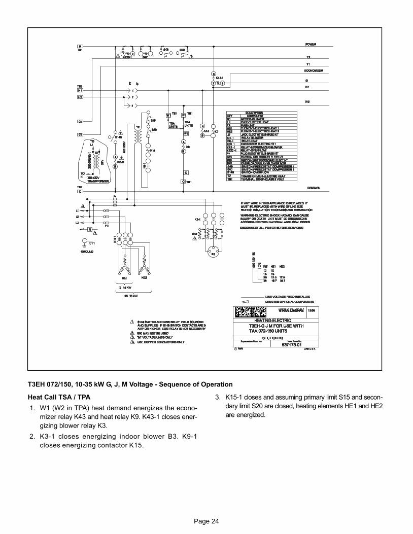
T3EH 072/150, 10−35 kW G, J, M Voltage − Sequence of Operation
Heat Call TSA / TPA
1. W1 (W2 in TPA) heat demand energizes the econo-
mizer relay K43 and heat relay K9. K43−1 closes ener-
gizing blower relay K3.
2. K3−1 closes energizing indoor blower B3. K9−1
closes energizing contactor K15.
3. K15−1 closes and assuming primary limit S15 and secon-
dary limit S20 are closed, heating elements HE1 and HE2
are energized.