TA SERIES AND SERIES 78K - Manuals...
31
TA SERIES 786/7871788/789 AND SERIES 78K Tour & Andersson calibrated balancing valves offer a reliable, simple and cost effective way to measure and balance all flow rates. Full throttling range is achieved by 4, 8, 12, 16, 20 or 22 full turns of the handwheel, enabling a precise setting. This high degree of accurate adjustment means that the system can be balanced precisely. The actual pressure drops in heating and cooling systems are difficult to establish by calculation because water flows vary from design flows. They can be corrected easily by regulating the desired water flow with Tour & Andersson globe style balancing valves. By measuring the pressure drop across measuring perts at a particular handwheel selling, the water flow for the valve size can be read easily from the appropriate pressure drop graph or flow balancing wheel. If the flow does not conform with that specified, adjust the valve and repeat the measuring procedure until the correct flow has been obtained. NOTE: All Tour & Andersson balancing valves include a concealed memory feature with a locking tamper-proof setting. Series 78K and TA Series 786 and 787 valves have an Ametal® body. Ametal is a copper alloy that eliminates the added expense of dielectric fittings. TA Series 788 and 789 balancing valves have ductile iron bodies and Ametal or ductile iron trim, depending on size. Test ports feature self-sealing construction for insertion-type pressure or temperature probes. All valves are rated from -4°F/-20°C to +250°F/+120°C. Service will also be governed by the connecting coupling gasket ratings for grooved and flanged valves. Insulation kits are available for 1h 6"/15 - 150 mm sizes for Series 78K and TA Series 786, 787, 788 and 789 balancing valves. TA Balancing valves provided by Victaulic can be ordered individually or as a component of the Series 799 or 79V KOII.-KIT Coil Pack. See the Series 799/79V Contractor Order Form (A) on page 9 of publication 08.30 for help ordering your Victaulic KOII.- KIT Coil Pack. Victaulic KOII.-KIT Coil Packs provide a simplified, quality coil installation while ensuring optimal hydronic systems design requirements are met. The Series 799/79V is suitable for a variety of hot and cold water applications including treated and untreated water systems. The Victaulic KOII.-KIT Coil Pack consists of the following components: Series 78Y Y-Strainer/Ball Valve or Series 78T Ball Valve Union Combination, two Coil Hoses, a Series 78U Union Port Fitting and a TA balancing valve. There are two options when ordering a Victaulic KOII.-KIT Coil Pack: Series 799 KOII.-KIT Coil Pack or Series 79V KOII.-KIT Call Pack with ATC Valve. The Series 799 and Series 79V comes standard with the components listed above. Additionally, the Series 79V includes the option to have the ATC valve of your choosing assembled and shipped with the Victaulic KOII.-KIT Coil Pack. Please note that when ordering a Series 79V, Victaulic offers one balancing valve, the Series 78K. Specify either Series 799 or Series 79V when ordering. For added convenience, when coil hoses are ordered as a component of the Series 799 or 79V KOII.-KIT Coil Pack, all hoses can be provided pre-connected to the Series 78Y or 78T on the supply side and the Series 78U on the return side (specify connection preference when ordering). For information on Victaulic KOII.-KIT Coil Packs, refer to publication 0830. COIL VICTAUlIC SERIES 799179V KOIL·KIT m COIL PACK SUPPLY RETURN JOB/OWNER System No. _ Location _ CONTRACTOR Submitted By _ Date _ ENGINEER Spec Sect Para _ Approved _ Date _ www.vittaulk.tom VICTAULIC IS A REGISTERED TRADEMARK OF VICTAULIC COMPANY. © 2011 VICTAlJLlC COMPANY. ALL RIGHTS RESERVED.
Transcript of TA SERIES AND SERIES 78K - Manuals...

TA SERIES 786/7871788/789 AND SERIES 78K
Tour & Andersson calibrated balancing valves offer a reliable, simple and cost effective way tomeasure and balance all flow rates. Full throttling range is achieved by 4, 8, 12, 16, 20 or 22full turns of the handwheel, enabling a precise setting. This high degree of accurate adjustmentmeans that the system can be balanced precisely.
The actual pressure drops in heating and cooling systems are difficult to establish by calculationbecause water flows vary from design flows. They can be corrected easily by regulating thedesired water flow with Tour & Andersson globe style balancing valves. By measuring thepressure drop across measuring perts at a particular handwheel selling, the water flow for thevalve size can be read easily from the appropriate pressure drop graph or flow balancing wheel.If the flow does not conform with that specified, adjust the valve and repeat the measuringprocedure until the correct flow has been obtained.
NOTE: All Tour & Andersson balancing valves include a concealed memory feature with alocking tamper-proof setting.
Series 78K and TA Series 786 and 787 valves have an Ametal® body. Ametal is a copper alloythat eliminates the added expense of dielectric fittings.
TA Series 788 and 789 balancing valves have ductile iron bodies and Ametal or ductile irontrim, depending on size. Test ports feature self-sealing construction for insertion-type pressureor temperature probes.
All valves are rated from -4°F/-20°C to +250°F/+120°C. Service will also be governed by theconnecting coupling gasket ratings for grooved and flanged valves.
Insulation kits are available for 1h 6"/15 - 150mm sizes for Series 78K and TA Series 786,787, 788 and 789 balancing valves.
TA Balancing valves provided by Victaulic can be orderedindividually or as a component of the Series 799 or 79V KOII.-KITCoil Pack. See the Series 799/79V Contractor Order Form (A) onpage 9 of publication 08.30 for help ordering your Victaulic KOII.KIT Coil Pack.
Victaulic KOII.-KIT Coil Packs provide a simplified, quality coilinstallation while ensuring optimal hydronic systems designrequirements are met. The Series 799/79V is suitable for a variety ofhot and cold water applications including treated and untreatedwater systems.
The Victaulic KOII.-KIT Coil Pack consists of the following components:Series 78Y Y-Strainer/Ball Valve or Series 78T Ball Valve UnionCombination, two Coil Hoses, a Series 78U Union Port Fitting and aTA balancing valve. There are two options when ordering a VictaulicKOII.-KIT Coil Pack: Series 799 KOII.-KIT Coil Pack or Series 79VKOII.-KIT Call Pack with ATC Valve.
The Series 799 and Series 79V comes standard with the componentslisted above. Additionally, the Series 79V includes the option to havethe ATC valve of your choosing assembled and shipped with theVictaulic KOII.-KIT Coil Pack. Please note that when ordering aSeries 79V, Victaulic offers one balancing valve, the Series 78K.Specify either Series 799 or Series 79V when ordering.
For added convenience, when coil hoses are ordered as a componentof the Series 799 or 79V KOII.-KIT Coil Pack, all hoses can beprovided pre-connected to the Series 78Y or 78T on the supply sideand the Series 78U on the return side (specify connection preferencewhen ordering).
For information on Victaulic KOII.-KIT Coil Packs, refer to publication0830.
COIL
VICTAUlIC SERIES 799179V KOIL·KITm COIL PACK
SUPPLY
RETURN
JOB/OWNER
System No. _
Location _
CONTRACTOR
Submitted By _
Date _
ENGINEER
Spec Sect Para _
Approved _
Date _
www.vittaulk.tomVICTAULIC IS A REGISTERED TRADEMARK OF VICTAULIC COMPANY. © 2011 VICTAlJLlC COMPANY. ALL RIGHTS RESERVED.

08.16
TA SERIES 7861787/7881789 AND SERIES 78K
MATERIAL SPECIFICATIONS Balancing ValvesBODY:
Series 78K and TA Series 786, 787: Ametal, (pressure die cast, nonporous copper alloy)TA Series 788, 789: Ductile iron, ASTM A536 Grade 60-40-18 (BS Grade 400/15)
BODY COATING:TA Series 788, 789: 2 '12, 3, 4" - Epoxy resin coated
5-16"- painted
TRIM: (Bonnet, Stem and Restriction Cone)Series 78K and TA Series 786, 787: AmetalTA Series 788, 789:
Bonnet 2'12 6" - AmetalBonnet - 8 - 16" - Ductile IronStem: AmetalRestriction Cone: Ametal
UNION:Series 78K: Brass with EPDM o-ring
TAILPIECE & ADAPTER:Series 78K: DZR Brass
SEAT:Series 78K, and TA Series 786, 787: AmetalTA Series 788, 789: Ductile Iron
SEAT SEAL:Series 78K and TA Series, 786, 787, 788, 789: EPDM
STEM SEALS: EPDM
PROBE SEALS: EPDM
OPTIONAL SEAT, STEM AND PROBE SEALS: Fluoroelastomer (available on 1 '12 and 2" TA Series787; 2'12 10" TA Series 789 (except 5"). Contact Victaulic for availability.
HANDWHEEL:Series 78K and TA Series 786, 787 Red Polyamide plasticTA Series 788, 789: 2 Y.2-6" - Red Polyamide plastic
8-16" - Aluminum
OPTIONAL EQUIPMENT:TA Series 786, 787: Drain kit-AmetalTA Series 786, 787: Insulation Kit-Polyurethane. Also available on TA Series 789 2 '12-6" sizes.
Allen Wrench Sizes3 mm memory Y.2 - 2" TA Series 786,788 valves5 mm memory 2 Y.2 - 12" TA Series 788 & 2'12 - 6" TA Series 789 valves8 mm memory 8 - 16" TA Series 789 valves5 mm drain kit Y.2 - 2" TA Series 786 valves
www.victaulic.comVICTAULIC IS A REGISTEREO TRADEMARK OF VICTAULIC COMPANY. © 2011 VICTAULIC COMPANY. ALL RIGHTS RESERVED.
TA SERIES 786087088/789 AND SERIES 78K
COMPARISON OF BALANCING VALVETHROTTLING CHARACTERISTICS
• This curve Illustrates the advantage of thefour (4) turn adjustment available with Tour& Andersson balancing valves (~ - 2"/15- 50 mm). Valves 2 W'/65 mm) and largerhave 8, 12 or 16 turns.
• A 90° fully open to closed valve requiresjust a 12° change in adjustment to equal30% change of the flow.
• A 360° fully open to closed valve wouldrequire 96° change In adjustment to equalthe same 30% change In the flow measurement.
• Tour & Andersson balancing valves wouldrequire a 408° change In adjustment toequal the same 30% change in the flow.
100
w 90\::I:z« 80'"...:z 70w:Ew 60a::::lVI 50 I«w:E 40 I
~ I... 301.1. I1.1.0 20 I...:z
10 Iwv'" Iw o 160 10- 3601 720 I 1080
II-l>! 9612+1,+ I+-- 408 -----+1
DEGREE OF VALVE STEM ROTATION
08.16
www.victaulic.comVICTAULIC IS A REGISTERED TRADEMARK OF VICTAULIC COMPANY. © 20l! VICTAULIC COMPANY.. ALL RIGHTS RFSERVED

08.16
TA SERIES 786/7871788089 AND SERIES 78K
Balancing ValveTA SERIES 786 Solder EndTA SERIES 787 FemaleThreaded End
TA SERIES 786TYPICAL \7 - 2"/15 - 50 MM SIZES y, 0.840 350 4.00 1.4 350 4.00 1.5
r~A---1 15 21.3 89 102 0.6 89 102 0.7
~l1:1 1.050 381 400 1.4 381 4.00 1.620 26.7 97 102 06 97 102 0.7
1 1.315 4.31 450 1.9 4.31 450 2.025 33.7 110 114 09 110 114 0.9
11.4 1.660 4.88 4.31 2.4 4.88 4.31 2.632 42.4 124 110 1.1 124 110 1.2
1 Y2 1.900 5.13 4.75 3.1 5.13 475 33TA SERIES 787 40 48.3 130 121 1.4 130 121 1.5
TYPICAL \7 - 2"/15 - 50MM SIZES 2 2.375 6.13 4.75 4.5 6.13 4.75 5.050 60.3 156 121 20 156 121 23
VALVE SELECTION GUIDE
0105
0.420 1.5
1 0.5 30025 1.7 114.0
11,4 1.660 09 48.032 42.4 33 182.0
1Y2 1.900 13 6.6 20.0 66.040 48.3 4.9 25.0- 250.0
2 2.375 2.0 - 360 110.050 60.3 76 1360 416.0
IMPORTANT NOTES:valves should be sized in accordance with the GPM/LPM flows (and not in relation to pipeline size).
valves based on the minimum or maximum flow rates is not recommended. Valves should bethe nominal flow rate only. The Minimum Flow is calculated from the minimum setting of the
a minimum drop 1 Ft. WG (= 3 kPa). The Nominal Flow is calculated from maximum openof the valve the minimum recommended drop, 2 Ft. WG (= 6 kPa). The Maximum Flow is calcu-
lated the maximum open setting of the valve the maximum drop, 20 Ft. WG (= 60 kPa). A com-program, TA-Select. is available for calculation of valve position and other aPI)!icaticJns.For information regarding Allen Wrench sizes see the Material section on page
MEASURING ACCURACY:The hand wheel zero position is calibrated and must not be changed. Valves have an accuracy of flow measurement of 2% to 3% when used within their recommended flow range and installed in accordance with the figurebelow.Note: For the most accurate results, a Series 734 TA SCOPE or Series 73M CMI should be used. However, any differ-
e~:;;=rYbeuse~
The illustration above relates to the accuracy of differential pressure measurement and is not an installation requirement.
www.victaulic.comVICTAULIC IS A REGISTERED TRADEMARK OF VICTAULIC COMPANY. © 2011 VICTAULIC COMPANY. ALL RIGHTS RESERVED.

08.16
TA SERIES 786/787/788/789 AND SERIES 78K
Balancing ValveSERIES 78K Male x Female
Optional tailpieces are available for double reductions, or for changing end configurations from sweat tothreaded or threaded to sweat. If needed, specify tailpiece option when ordering.
575 4.00 1.715 146 102 0.8
% 5.94 4.00 1.820 151 102 0.8
1 627 4.50 27SERIES 78K 25 159 114 1.2
TYPICAL v.. - 2"/15 - 50 MM SIZES lY4 7.37 4.72 4.132 187 120 1.9
% % 5.99 7.97 4.00 2.320 20 152 202 102 1
1 6.81 4.50 2.225 173 114 1.0
1 V2 766 4.75 5040 195 121 2.3
1 1 770 9.01 4.0225 25 186 229 1.8
11;4 7.83 4.31 2.832 199 109 13
1 V2 7.66 4.75 5.240 195 121 2.4
2 8.91 4.75 7.350 226 121 3.3
11,4 1:4 8.18 9.66 4.72 5.5232 32 208 245 120 2.5
1Y? 8.21 4.75 3640 209 121 1.6
2 8.91 4.75 7.550 226 121 3.4
1Y2 1Y1 900 10.37 4.75 7.1640 40 229 263 121 3.2
2 9.02 4.75 5.350 229 121 2.4
2 2 4.75 7.1950 50 121 3.3
www.victaulic.comVICTAULIC IS A REGISTERED TRADEMARK OF VICTAULIC COMPANY. © 2011 VICTAULIC COMPANY. ALL RIGHTS RESFRVED

08.16
TA SERIES 786178717881789 AND SERIES 78K
VALVE SELECTION GUIDEBalancing ValveSERIES 78K Male x Female
SERIES 78KTYPICAL 'h - 2"115 - 50 MM SIZES "20
125
1\432
1Yl40
250
" 0420 1.5
1 0.5 30025 1.7 114.0
1% 0.9 50 - ISO 48032 3.3 18.9 - 56.8 182.0
" 04 2.0 60 20020 1.5 76 227 75.7
1 0.5 100 30025 1.7 14.8 379 114.0
1 Y2 1.3 6.6 200 66.040 4.9 250.0
I OS 39 - 10.0 30025 1.7 14.8 - 379 114.0
1lil 0.9 5.0-15.0 48.032 3.3 189-568 182.0
I:;' 1.3 66 20.0 66040 4.9 25.0 757 250
2 2.0 - 360 110.050 76 4U -1360 416.0
1% 09 5.0-· ISO 48.032 3.3 189- 568 182.0
In 1.3 6.6 - 20,040 4.9 250 - 75.7
2 2.0 - 360 110.050 76 47.7 1360 416.0
1 Y2 1.3 6.6 -40 4.9 250
2 2.0 i60 110.050 7.6 - 1360 416.0
2 2.0 - 36.0 110.050 76 47.7 - 1360 416.0
IMPORTANT NOTES: (SEE PAGE FOR MEASURING ACCURACY)
Balancing valves should be sized in accordance with the GPMILPM flows (and not in reiation to pipeline size). Sizing balancing valves based on the minimum or maximum flow rates is not recommended. Valves should be sized using the nominalflow rate only. The Minimum Flow is calculated from the minimum open setting of the valve and a minimum pressure drop1 Ft. WG (= 3 kPa). The Nominal Flow is calculated from the maximum open of the valve and the minimum recom-mended pressure drop, 2 Ft. WG (= 6 kPa). The Maximum Flow is calculated from maximum open setting of the valveand the maximum pressure drop, 20 Ft. WG 60 kPa).
Note: A computer program, TA-Select, is availabie for calculation of vaive handwheel pre-set position and other appiications.Note: For information regarding Allen Wrench sizes see the Material Specifications section on page 2.Note: For the most accurate results, a Series 734 TA SCOPE or Series 73M CMI should be used. However, any differentialpressure meter may be used.
www.victaulic.com
vrCTAUlIC IS A REGISTERED TRADEMARK OF VICTAUlIC COMPANY. © 2011 VICTAUlIC COMPANY. All RIGHTS RESERVED.

08.16
TA SERIES 786/787/788/789 AND SERIES 78K
Balancing ValveTA SERIES 788 Flanged End(Class 150 RF, ASME/ANSI 816.42)TA SERIES 789 Grooved End
I~~ A ------>j 2V2 2.875 11.38 800 24.0 11.38 800 14.065 73.0 289 203 10.9 289 203 6.4
3 3500 12.25 8.63 31.0 12.25 863 20.080 88.9 311 219 14.1 311 219 9.1
4 4500 13.75 9.44 430 13.75 9.44 31.0100 114.3 350 240 19.6 350 240 14.1
5 5.563 15.75 1088 620 1088 500125 1413 400 276 285 400 276 227
TA SERIES 788 6 6.625 1888 1125 82.0 18.88 1125 690TYPICAL 2>,; - 16'/65 - 400 MM SI2ES 150 168.3 480 286 375 480 286 31.3
8 8.625 2363 1700 168.0 2363 17.00 140.0200 219.1 600 432 765 600 432 63.7
10 10.750 28.75 17.75 270.0 28.75 17.75 202.0250 273.0 730 451 122,9 730 451 91.9
12 12.750 3350 19.00 3600 3350 1900 280,0300 323.9 851 483 163.9 851 483 127.4
14 14.00 3860 2300 655350 3556 980 584 297
TA SERIES 78916 16.00 43.30 2520 895
TYPICAL 2>,; 12'/65 300MM SIZES400 406.4 1100 640 406
VALVE SELECTION GUIDE
2Y2 2.875 1.4 380 100.0 290,065 730 5.3 144.0 - 3790 1097.7
3 3500 1.5 31.0 - 1300 410,080 88.9 57 117.0 - 4930 1551.9
4 4500 1.9 68.0- 2000 6500100 114.3 7.2 257.0 - 7570 2460.3
5 5563 900 - 3200 1020.0125 141.3 15.9 341.0- 1211.0 3860.7
6 6.625 50 450,0 1430.0150 168.3 189 - 1703.0 5412.6
8 8625 30.0 2600.0200 219.1 1136 9841.0
10 10.750 700 540.0 - 13000 4040.0250 2730 2650 20440 - 4921.0 15291.4
12 12,750 115,0 960.0 1500,0 4950,0300 3239 435.3 36340 - 56780 18735,8
141 14.00 830 1020.0 2700.0 7414.0350 3556 314.0 3861,0 10220.0 280620
16t 16.00 950 1330,0 3400.0 9371.0400 406.4 3600 5034.0 - 12869.0 35469,0
t Only the TA Series 788 Flanged End Balancing Valves is available in 14" and 16" (350 mm and 400 mm) sizes.
IMPORTANT NOTES: (SEE PAGE 4 FOR MEASURING ACCURACY)
valves should be sized in accordance with the GPM/LPM flows (and not in relation to size).valves based on the minimum or maximum flow rates is not should
nominal flow rate only. The Minimum Flow is calculated from the minimum openof the valve a minimum drop 1 Ft WG (= 3 kPa), The Nominal Flow is calculated from themum open setting of the and the minimum recommended pressure drop, 2 Ft WG (= 6 kPa),The Maximum Flow is calculated from the maximum of the valve and the maximumdrop, 20 Ft WG (= 60 kPa).A computer for calculation of valve harldVllheelpre-set position and other applications.
Note: For information regarding Allen Wrench sizes see the Material Specifications section on page 2,
Note: For the most accurate results, a Series 734 TA SCOPF or Series 73M CMI should be used, However, anydifferential pressure meter may be used.
www.victaulic.com
VICTAULIC IS A REGISTERED TRADEMARK OF VICTAULIC COMPANY. © 2011 VICTAULIC COMPANY, ALL RIGHTS RESERVED
08.16
TA SERIES 734Series 734 TA SCOPE is an instrument designed to help professionalsverify, measure and maintain complex systems quickly and efficiently,lowering maintenance costs by saving time and removing the hasslefrom the balancing and measuring process.
Series 734 TA SCOPE is a wireless, handheld device for the swift andaccurate measurement of differential pressure, flow, temperature andpower.
An independent sensor communicates with the TA SCOPE to deliverdata quickly, thereby enabling contractors to balance a system,troubleshoot hydronic problems and log system performance.
TA SCOPE
CMI Pressure Differential MeterTA SERIES 73MTA CMI is a computer programmed measuring instrument. It is ahandheld instrument for measuring differential pressure, temperatureand flow through balancing valves in hydronic systems. It consists ofa sensor unit and an instrument unit that has been programmed withthe TA valve characteristics, which makes it possible to take a directreading of flow and differential pressure.
www.victaulic.comVICTAULIC IS A REGISTERED TRADEMARK OF VICTAULIC COMPANY. © 2011 VICTAULIC COMPANY. All RIGHTS RESERVED.
TA Select Computer ProgramTA Select helps you choose the right balancing valve, taking the desiredflow rate and pressure drop into consideration. The software will advisethe correct combination of valve, handwheel position and pipe size tocorrectly balance the system. A sophisticated viscosity correction procedure displays the density, viscosity, specific heat and freeZing pointof fluids such as glycols and brines. It also displays the true value offlow through each valve.
The program will also size the pipe, generate Cv values for the ATCvalves and give pre-set information for all TA valves on the project.
TA SERIES 78617871788/789 AND SERIES 78K
Link Differential Pressure SensorTA SERIES 736• Provides connection between a bUilding's heating and cooling and
bUilding's monitoring system (BMSl.
• Continuously measures the flow and differential pressure through andacross the Tour & Andersson balancing valves.
• Measurement probes provided for direct connection to the measurement points on all TA Series 786, 787, 788, and 789 balancing valves.

08.16
TA SERIES 786/787/788089 AND SERIES 78K
Drain KitSERIES 786-0K
• A separate drain kit with a %"/20mm connection is available for Series 786 and Series 787 valves
• Kit must be field mounted
• Kit comes complete with 2 gaskets and a hexnut.
• Partcode= K-OOO-786-CBV
AccessoriesPROBE PORT
TA SERIES 786/787/7881789
D
TA SERIES 7881789
786/787112 ~ 2
K-000740-003 1.75IS 50 45
788/7892Y, - 16
K-000740-002 38 1.1965 - 400 10 30
788/7892Y2 -16
K-000740-00138 350
65 400 10 89
www.victaulic.comVICTAULIC IS A REGISTERED TRADEMARK OF VICTAUUC COMPANY. © 2011 VICTAULIC COMPANY. ALL RIGHTS RESERVED.

08.16
TA SERIES 786/787/788/789 AND SERIES 78K
UNIVERSAL GAUGE METERCONVERSION KIT
HANDWHEELS
• This kit includes 2 probes, necessary fittings, flow wheel and instruction sheet.
• Partcode= K-OOO-738-100
TA SERIES 7861787PLASTICI> 2"
TA SERIES 788/789PLASTIC21> - 6"
TA SERIES 788/789ALUMINUM
8 16"
BALANCING WHEEL By using the balancing wheel it is easy to determine the relationshipbetween flow, pressure drop and the handwheel setting values forall valve sizes. Order the balancing wheel from your nearest Victaulicrepresentative.
www.victaulic.com
VICTAULIC IS A REGISTERED TRADEMARK OF VICTAULIC COMPANY. © 2011 VICTAULIC COMPANY. ALL RIGHTS RESERVED.

08.16
TA SERIES 786f787f788/789 AND SERIES 78K
PREFAB INSULATIONTA SERIES 786 & TA SERIES 787
V2&3J.1 K-004-784IN5531 354 4D6 551
15 &20 135 90 103 140
\09 D1
K-010-784-IN5 5.59 3.70 4.06 63025 142 94 103 160
114 K-012-784-INS 614 4.17 4.06 7.0932 156 106 103 180
1V2 665 4.25 4.45 8.43
~:~40
K-014-784-IN5 169 108 113 214
I+--~ L ..__.-.1 2 K-020·784 INS 701 4.25 4.49 96550 178 108 114 245
PREFAB INSULATIONTA SERIES 788 & TA SERIES 789
217 K-024-784-IN5177S 10.63 1063
65 451 270 270
E]@3 K-030-784-INS 1900 11.44 11.44
80 483 291 291
4 K-040-784-INS 20.50 12.63 12.63100 521 321 321
k-- L ---------..I 5 K-050-784-INS 22.50 13.75 13.7S125 572 349 349
@XV6 K-060784 INS
2600 1500 15.00150 660 381 381
k-CMin.--..I
www.victaullc.comVICTAULIC IS A REGISTERED TRADEMARK DF VICTAULIC COMPANY. © 2011 VICTAULIC COMPANY. ALL RIGHTS RESERVED.
08.16
TA SERIES 786n87n881789 AND SERIES 78K
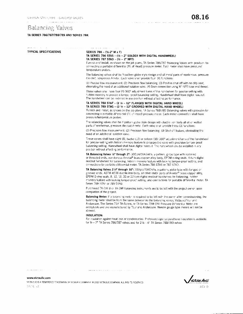
TYPICAL SPECIFICATIONS SERIES 78K - (112-2" M x F)TA SERIES 786 STAS - ('12 - 2" SOLDER WITH DIGITAL HANDWHEEL)TA SERIES 787 STAD - ('12 - 2" NPTlFurnish and install, as shown on the job plans, TA Series 786/787 Balancing Valves with provision forconnecting a portable differential (Ft. of Head) pressure meter. Each meter shall have pressure/temperature probes.
The balancing valves shall be Y-pattern globe style design and all metal parts of nonferrous, pressuredie cast, nonporous Ametal. Each valve shall provide four (4) functions:
(l) Precise flow measurement, (2) Precision flow balancing, (3) Positive shut-off with no drip seat,eliminating the need of an additional isolation valve, (4) Drain connection using :lA" NPT hose end thread.
These valves shall have four (4) 360 0 adjustment turns of the handwheel for precise setting withhidden memory to provide a tamper-proof balancing setting. Handwheel shall have digital readout.The handwheel can be installed in any position without affecting performance.
TA SERIES 788 STAF - (2 '12 - 12" FLANGED WITH DIGITAL HAND WHEEL)TA SERIES 789 STAG - (2 '12 - 12" GROOVED WITH DIGITAL HAND WHEEL)Furnish and install, as shown on the job plans, TA Series 788/789 Balancing valves with provision forconnecting a portable differential (Ft. of Head) pressure meter. Each meter connection shall havepressure/temperature probes.
The valancing valves shall be Y-pattern globe style design with ductile iron body all other wettedparts of nonferrous, pressure die cast Ametal. Each valve shall provide three (3) functions:
(l) Precision flow measurement, (2) Precision flow balancing, (3) Shut-off feature, eliminating theneed of an additional isolation valve.
These valves shall have eight (8), twelve (12) or sixteen (16) 3600 adjustment turns of the handwheelfor precise setting with hidden memory feature to program the valve with precision tamper-proofbalancing setting. Handwheel shall have digital readout. The handwheel can be installed in anyposition without affecting performance.
TA Balancing Valves 'h" through 2": 300 psil2065 kPa, y-pattern, globe type with solderedor threaded ends, non-ferrous Ametal® brass copper alloy body, EPDM o-ring seals. 4-lurn digitalreadout handwheel for balancing, hidden memory feature with locking tamper-proof setting, andconnections for portable differential meter. TA Series 786 STAS or 787 STAD.
TA Balancing Valves 2 'h" through 16": 300psi/2065 kPa, y-pattern, globe type with flanged orgrooved ends, ASTM A536 ductile iron body, all other metal parts of Ametal® brass copper alloy,EPDM O-ring seals. 8, 12, 16, 20 or 22 turn digital readout handwheel for balancing, hiddenmemory feature with locking tamper-proof setting, and connections for portable differential meter. TASeries 788 STAF or 789 STAG.
Purchased TA CBI-II or TA CMI balancing instruments are to be left with the project owner uponcompletion of the project.
Balancing Meter: If a balancing meter is required to be left with the owner after commissioning, thebalancing meter shall be from the same provider as the balancing valves, Victaulic/Tour andAndersson. The Series 734 TA-Scope, or TA Series 73M CMI Pressure Differential Meter areacceptable and are manufactured by Tour and Andersson. Needle gauge type meters will not beallowed.
INSULATION:For insulation against heat loss or condensation. Preformed rigid polyurethane insulation is availablefor 'h 2" TA Series 786/787 valves and for 2'h - 6" TA Series 788/789 valves.
www.victaulic.comVICTAULIC IS A REGISTERED TRADEMARK OF VICTAULIC COMPANY. © 2011 VICTAULIC COMPANY. ALL RIGHTS RESERVED

08.16
TA SERIES 786/787/788/789 AND SERIES 78K
CORRECTION FACTORS
SIZING A BALANCING VALVE
For liquids other than water, the flow values from the balancing wheel can be adjusted as follows:
Divide the flow rate (as indicated by the balancing wheel) by the square root of the specific gravity.
Actual Flow
This applies to liquids having, on the whole, the same viscosity as water, i.e. most water/glycol mixturesand water/brine solutions at room temperature. At low temperatures, the viscosity increases andlaminar flow may occur in certain valves. The risk increases with small valves, low settings and lowdifferential pressures.
A computer program (TA-Select) is available for calculation of pre-setting values and other applications.When the flow setting is verified or changed to the final setting, the memory stop should be set.Contact Victaulic for further information.
When lip and the design flow rate are known, use the formula shown to calculate the Cv value or usethe graphs on page 16 - 18. The Tour & Andersson balancing wheel can also be used.
C = 152 ~-, .Jl:,p
q in GPM, 6p in Ft of Hp
q in GPM, i1p in psi
A computer program, TA-Select, is available from Victaulic for calculation of pre-setting values andother applications.
www.victaulic.comVICTAULIC IS A REGISTERED TRADEMARK OF VICTAULIC COMPANY. © 2011 VICTAULIC COMPANY All RIGHTS RESERVED

08.16
TA SERIES 786n87n88/789 AND SERIES 78K
Cv VALUES FOR VARIOUSHANDLE SETTINGSSERIES 78Kand TA SERIES 786nS7
The values below or the graph on page 15 may be used when calculating and sizing a piping system.
0.50 0.15 0.59 0.70 1.32 2.03 2.97
1.00 0.25 088 1.19 2.20 3.83 4.87
1.50 0.36 138 2A4 3.60 5.34 8.35
2.00 0.66 2.20 4.20 SAO 7.08 13.60
2.50 1.02 324 6.15 824 10.20 18.80
3.00 1.60 4.49 8.00 11.00 14.60 2490
3.50 2.30 5.51 9.28 13.70 18.60 30.70SERIES 78K
4.00 ' 292 6.61 10.09 16.50 2230 38.00
§ Cv ~ GPM at a L1P of 1psi/7 kPa) through the valve at any given setting.
1psi ~ 2.31 ft. of H2O.
'Full open valve.
TA SERIES 786
TA SERIES 787
www.victaulic.com
VICTAULIC IS A REGISTERED TRADEMARK OF VICTAULIC COMPANY. © 2011 VICTAULIC COMPANY.. ALL RIGHTS RESERVED.

TA SERIES 786n87/7881789 AND SERIES 78K
08.16
Cv VALUES FOR VARIOUSHANDLE SETTINGSTA SERIES 788/789
TA SERIES 788
TA SERI ES 789
The values below or the graph on page 16 and 17 may be used when calculating and sizing a piping system.
050 2.09 2.32 2.90 6.38 754
1.00 3.94 4.64 696 12.20 13.90
1.50 568 6.96 1040 1800 2550
2.00 7.54 928 13.30 24.90 4640 4640 104.00
250 10.80 12.80 18.60 31.30 7540 5800 12800
3.00 18.90 1620 3020 41.80 11600 7540 16200 174.00 124.87 143.20
350 29.70 22.60 51.00 63.80 15700 104.00 226.00 267.00 14718 16955
400 40.90 3360 73.10 9630 19600 139.00 296.00 34800 16955 19550
450 51.60 4760 92.80 132.00 240.00 191.00 371.00 429.00 194.76 238.29
5.00 6030 63.80 114.00 16400 281.00 261.00 44700 522.00 237.14 30244
550 70.20 78.90 13300 194.00 324.00 331.00 516.00 621.00 290.99 37347
6.00 78.90 92.80 15300 229.00 362.00 39400 580.00 719.00 345.98 442.21
650 84.70 107.00 16800 25500 39400 464.00 632.00 800.00 40326 51438
700 8930 11900 18400 289.00 426.00 505.00 68400 87000 46283 589.99
750 9340 131.00 20300 320.00 454.00 545.00 76600 945.00 53959 67592
800 98.60 • 139.00 • 22000 • 348.00 • 48700 • 59700 841.00 103200 636.96 779.02
9.00 690.00 951.00 1125.00 898.17 1024.18
10.00 754.00 109000 1206.00 109636 1306.01
11.00 82400 1218.00 1299.00 1260.18 1432.03
12.00 88700 • 1375.00 ' 1392.00 1443.48 1603.87
13.00 1531.00 1626.78 1787.17
14.00 1589.00 184445 1981.92
1500 162400 201629 222250
16.00 168200 • 214231 2451.63
17.00 224542 2612.01
1800 2337.06 2760.94
19.00 2440.17 2898.42
20.00 252036* 3012.98
21.00 310463
22.00 3184.82'
§ Cv = GPM at a ,A,P of 1 psi/7 kPa) through the valve at any given setting.
1 psi =2.31 ft. of H2O.
'Full open valve.
www.victaulic.com
VICTAULIC IS A REGISTERED TRADEMARK OF VICTAULIC COMPANY. © 201t VICTAULIC COMPANY. All RIGHTS RESERVED

08.16
TA SERIES 786087/7881789 AND SERIES 78K
DiagramTA SERIES 786087and SERIES 78K
This graph shows the pressure drop across the pressure test points of the valve.
A straight line connecting the bars for flow rate, Cv and pressure drop shows the relationshipbetween these variables. The position for each valve size is arrived at by drawing a horizontal linefrom the Cv value obtained.
Example:
Wanted: Pre-setting for a 1" valve at a desired flow rate of 6.7GPM and a pressure drop of 3 ft.
Solution: Draw straight line joining 6.7GPM and 3 ft. This gives Cv ~ 5.9. Now draw a horizontal linefrom Cy '= 5.9. This intersects the bar for a 1" valve at the desired pre-setting of 2.35 turns.
NOTE: If the flow rate falls outside of the scale in the diagram, the reading can be made as follows:Starting with the example above, we get 3 ft., Cv 5.9 and the flow rate 6.7 GPM. At 3 ft. and Cv ~.59 we get the flow rate .67GPM. That is, for a given pressure drop, it is possible to read 10 times or0.1 times the flow and Cv values.
10
10010{)
10
70Setting, number of turns
50 0.5
504()
4030
30 25
2520
2015
15
10
0.3
0.1 0.7
07.3
10 3D')
os 0.25
0.50.4 40
0.40.25
0.350
0.0503 0.25
0.25 02 20
0.20.15
0.5 0.1530
0.1 100
0.1
Sizelis GPM Cv Kv 114' ,.
kPaTA Serie, 786/787 and Series 78K
0.2
05
0.3
10
20
25 40
OA ....... -- ......... -- ..............--------1----
www.victaullc.comVICTAULIC IS A REGISTERED TRADEMARK OF VICTAULIC COMPANY. © ZOll VICTAULIC COMPANY ALL RIGHTS RESERVED.

08.16
TA SERIES 786/7871788/789 AND SERIES 78K
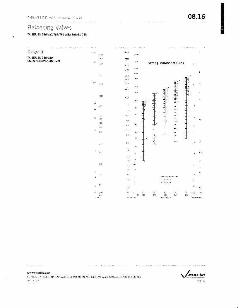
DiagramTA SERIES 788/789SIZES 2'h - 6"160·150 MM
This graph shows the pressure drop across the pressure test points of the valve.
A straight line connecting the flow rate scale, Cv and pressure drop shows the relationship betweenthese variables
Example:
Wanted: Pre-setting for a TA Series 788 or TA Series 789 2 W' at a desired flow rate of 47 GPM and apressure drop of 2 ft. WG.
Solution: Draw straight line joining 47 GPM and 2 ft. WG. This gives Cv = 50. Now draw a horizontalline from Cv 50. This intersects the flow rate scale for Series 788 2W at the desired pre-setting of4.5 turns.
1(}OO
4()() 1000
3':>0 700
20 I()() Setting, number of turns3()() 05
5()()
5()() 8")4()()
4()()I
'00 3DO 6
lDO
102()()1.')0 8")
2()()
150
1508")
1()()lDO 3')
1()() 8")I
10 6 - _r-70 -i()
5- -_s.. -50 .. - -- - ~o- -..c :;;... - -so - - ---0- - -
45 1030
4030 ).)
20
30 203')
3')15
20
20 10
10
1510 30''')
OS
40
10l:)
05SO
0.505 20
....J
OS04
2.1L5
0.3 30lDO
1/5 Cv Kv 4" 5'~ 6" FtWG kPil
Flow Valve factor JA Series 788/789 Pressure drop
www.victaulic.com
VICTAULIC IS A REGISTERED TRADEMARK OF VICTAULIC COMPANY. © 2011 VICTAULIC COMPANY. All RIGHTS RESERVED.
08.16
TA SERIES 786n87/788/789 AND SERIES 78K
Diagram 278 10000
4000 10000
TA SERIES 788/789 3)00 1000SIZES 8·16"/200·400 MM 200 7000 Setting, number of turns3000 05
5000
SOOO4000
40002000 3000
2500 3000
10020001)00
200016 ")
150014
1500 12
1000 10]t)(X)
1000 12")9 ')so 11
700 10100 9100
40 8')00
5")
400500
50030 4S0 10
300400
300 .')250
350
20 200300 200
1s0
150 4 ~)
20
200 100
100
10 70150 70 10
30")
50
4050
40
100 4030 IS
5025 30
70 20 20H)
20 * Recommended area
1; 25 db (A)25
15 n. 35 db (A)50
3010 100
I/s GPM K, C, 8" 10" Il" 14" 16" FtWG kPa
(US) DN 200 2S0 300 350 400Flow Valve-factor Series 788/789 Pressure drop
www.victaulic.com
VICTAULIC IS A REGISTERED TRADEMARK OF VICTAULIC COMPANY. © 2011 VICTAULIC COMPANY ALL RIGHTS RFSFRVED.
~ -----------
TA SERIES 786/787/788/789 AND SERIES 78K
WARRANTY
NOTE
Refer to the Warranty section of the current Price List or contact Victaulic for details.
This product shall be manufactured by Victaulic or to Victaulic specifications. All products to beinstalled in accordance with current Victaulic installation/assembly instructions as recommendedby Tour and Andersson. Victaulic reserves the right to change product specifications, designs andstandard equipment without notice and without incurring obligations.
For complete contact information, visit www.victaulic.com
08.16 0930 REV 0 UPDATED 2/2011VICTAULIC IS A REGISTERED TRADEMARK OF VICTAULIC COMPANY. VICTAULIC COMPANY. ALL RIGHTS RFSERVED.

SIZES 1/2 TO 2 INCHI------E-----,1
1H
¢D------..l..
t, ' ,
L1
I------L-----l
SIZES 2-1/2 TO 4 INCH
1-----E-9------,
1H
I--------L--------<--t
DWG NO: FNW421
MODEL: 421
NOTES: rev 1• add L1dim. rev 2· corrected size ranges
R'DATE: 6-4-2008
LOC: PORTLAND
4120 NE Columbia BlvdPortland, OR 97211Phone (503) 287·8383Fax (503) 281·9877
FNW!M
THIS DRAWING CONTAINS CONFIDENTIAL AND PROPlETARY lNFORMATlON OF FNWVALVE AND IS SUBMITTED TO YOU FOR THE LIMITED PURPOSE OF PROVIDING YOUINFORMATION ON PRODUCTS AND SYSTEMS PURCHASED FROM FNWVALVE. BYRECEIVING THIS DOCUMENT, YOU AGREE NOT TO DISCLOSE SUCH INFORMATIDN TOOTHERS EXCEPT BY WRITTEN PERMISSION OF FNW VALVE.
DATE: 8-2-Q5 BY: PEA UNITS: INCHES
SCALE: NONE APP'D: KMC PAGE(S): 1
TITLE/DESCRIPTION: Fig 421, 2PC BRASS BALL VALVE, SWEAT ENDS,FULL PORT
PAGE SIZE: 8,5 x 11L
Size 00 E L L1 H1/2 057 3.78 2.58 0.50 1.813/4 0.76 4.76 3.00 0.75 2.281 0.98 4.76 3.56 0.91 2.44
1-1/4 1.26 5.94 4.09 0.97 3.001-1/2 157 5.94 4.56 1.10 3.23
2 1.95 6.30 5.45 1.34 3.742-1/2 2.56 8.11
~1.48 4.64
3 305 811 1.67 5.234 3.94 10.27 10.25 ! 2.17 6.49
Ref. No. . Description Material Qty1 Body Brass CW 617N UNI EN 12165 12 Ball Brass CW 617N UN! EN 12165 1
(Nickel-Chrome Plated)
I 3 End Cap Brass CW 617N UNI EN 12165 14 Seat PTFE 26 Stem Brass CW 614N UNI EN 12164 17 Stem Packing PTFE 1 Set
7A Stem O-ring NBR 75 Shore A 18 Handle Fe 0011 UNI EN 10111 19 Handle Cover Vinyl 110 Thrust Washer PTFE 111 Gland Nut Zinc Plated Steel 6S 1
l1A Packing Gland Brass CW 614NUN!~13 Handle Nut Zinc Plated Steel 6S 1
NEW GENERATIONHIGH LOW
SYSTEM
A=12" +/- 1;2" B=29" C=2 %"
(Shown with option DT)
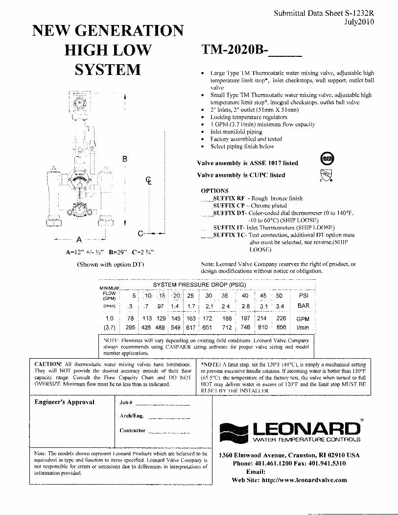
Submittal Data Sheet S-1232RJuly2010
TM-2020B------• Large Type TM Thermostatic water mixing valve, adjustable high
temperature limit stop*, inlet checkstops, wall support, outlet ballvalve
• Small Type TM Thermostatic water mixing valve, aqjustable hightemperature limit stop*, integral checkstops, outlet ball valve
• 2" inlets, 2" outlet (51mm X 51mm)• Locking temperature regulators• 1 GPM (3.7 l/min) minimum flow capacity• Inlet manifold piping• Factory assembled and tested• Select piping finish below
Valve assembly is ASSE 1017 listed
Valve assembly is CUPC listed
OPTIONS__SUFFIX RF - Rough bronze finish__SUFFIX CP - Chrome plated__SUFFIX DT- Color-coded dial thermometer (0 to 140°F,
-10 to 60°C) (SHIP LOOSE)__SUFFIX IT-Inlet Thermometers (SHIP LOOSE)__SUFFIX TC- Test connection, additional DT option must
also must be selected, see reverse.(SHIPLOOSE)
Note: Leonard Valve Company reserves the right of product, ordesign modifications without notice or obligation.
NOTE: Flowrates will vary depending on existing field conditions. Leonard Valve Companyalways recommends using CASPAK® sizing software for proper valve sizing and modelnumber applications.
CAUTIONl All thermostatic water mixing valves have limitations.They will NOT provide the desired accuracy outside of their flowcapacity range. Consult the Flow Capacity Chart and DO NOTOVERSIZE. Minimum flow must be no less than as indicated.
Engineer's Approval Job # _
Arch/Eng. _
Contractor _
*NOTE: A limit stop, set for 120°F (49°C), is simply a mechanical settingto prevent excessive handle rotation. If incoming water is hotter than 150°F(65.5°C), the temperature of the factory test, the valve when turned to fullHOT may deliver water in excess of 120°F and the limit stop MUST BERESET BY THE INSTALLER
®
__ LEONARD.. WATER TEMPERATURE CONTROLS
Note: The models shown represent Leonard Products which are believed to beequivalent in type and function to items specified. Leonard Valve Company isnot responsible for errors or omissions due to differences in interpretations ofinformation provided.
1360 Elmwood Avenue, Cranston, RI 02910 USAPhone: 401.461.1200 Fax: 401.941.5310
Email:Web Site: http://www.leonardvalve.com
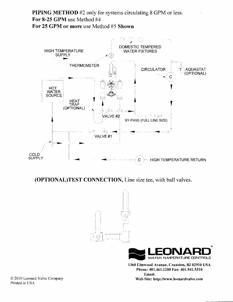
PIPING METHOD #2 only for systems circulating 8 GPM or less.For 8-25 GPM use Method #4For 25 GPM or more use Method #5 Shown
HIGH TEMPERATURESUPPLY
THERMOMETER
HOTWATER
SOURCE
HEATTRAP
(OPTIONAL)
DOMESTIC TEMPEREDWATER FIXTURES
CIRCULATOR
COLDSUPPLY C HIGH TEMPERATURE RETURN
(OPTIONAL)TEST CONNECTION, Line size tee, with ball valves.
© 2010 Leonard Valve CompanyPrinted in USA
®
__ LEONARD... WATER TEMPERATURE CONTROLS
1360 Elmwood Avenue, Cranston, RI 02910 USAPhone: 401.461.1200 Fax: 401.941.5310
Email:Web Site: http://www.leonardvalve.com

-------
®
"LEONARD_ WATER TEMPERATURE CONTROLS
INSTALLATION ADJUSTMENT SERVICEHIGH-LOW MANIFOLD
TM-2020BValve assembly is ASSE 1017 listed e
Valve assembly is CUPC listed ~MIMPORTANT! Provide serial numbers for both valves when ordering parts!!
Small valve manufactured after July 2007 starting with serial # TM26272
INSTALLATION
Bulletin G-IIE
June 2009
DOMESTIC OUTLET, DOMESTIC OUTLET,
HOT INLET COLD INLET
IHOT INLET
,COLD INLET
I. Type TM manifold systems are factory pre-assembledand tested and include large and small thermostatic watermixing valves which function as a system to meet bothhigh and low demand for tempered water.
2. System should be installed at a location where it caneasily be cleaned, adjusted or repaired.
3. System supplies must be connected as shown (Hot-left,Cold-right). Exercise caution when soldering.
4. Flush pipes thoroughly after system has beenconnected.
5. If this assembly is installed on a recirculated hot watersystem it MUST be piped according to LEONARD'SREQUIRED PIPING METHODS (see pages 4 & 5).
6. Refer to page 3 of this bulletin for correct SetupInstructions.
Maximum Operating Pressure 125PSI (860 KPA) for Hot and Cold Water.
CAUTION
All thermostatic water-mixing valves have limitations. They will not provide the desiredaccuracy outside of their flow capacity range. Consult the capacity chart on page 8. Minimumflow must be no less than as shown.
1360 Elmwood Avenue, Cranston, RI 02910 USAPhone: 401.461.1200 Fax: 401.941.5310
Email:Web Site: http://www.leonardvalve.com
ADJUSTMENT AND SERVICE
Leonard Type TM Thermostatic Water MixingValves are simple in design and may be easilycleaned, adjusted and repaired. If the installationis accessible, servicing may be completed withoutdisconnecting the valves.
NOTE: High Low Manifold Systems includeThermostatic Water Mixing Valves, which mustbe regularly maintained to provide bestperformance. Frequency of cleaning depends onquality of local water conditions and usage. SeeMaintenance Guide and Record MGR-I 000
~ WARNING ~These mixing valves are equipped with an adjustable high temperature limit stop factory set at approximately120°F (49°C) with an incoming hot water supply temperature of lS0°F (6S.soC). If the hot water supplytemperature of the job is greater than lS0°F (6S .S°C), the valves when turned to full HOT will deliver water inexcess of 120°F (49°C) and the limit stop MUST BE RESET BY THE INSTALLER!
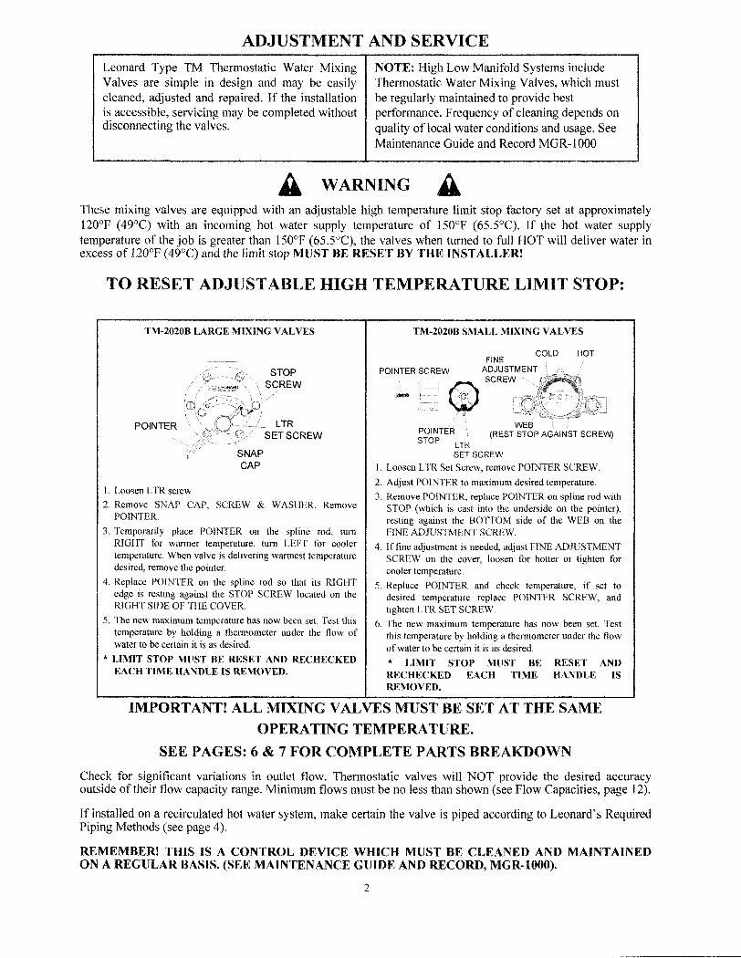
TO RESET ADJUSTABLE HIGH TEMPERATURE LIMIT STOP:
TM-2020B LARGE MIXING VALVES TM-2020B SMALL MIXING VALVES
I. Loosen LTR screw
2. Remove SNAP CAP, SCREW & WASHER, RemovePOINTER.
3. Temporarily place POINTER on the spline rod, tumRIGHT for warmer temperature, tum LEFT for coolertemperature. When valve is delivering warmest temperaturedesired, remove the pointer.
4. Replace POINTER on the spline rod so that its RIGHTedge is resting against the STOP SCREW located on theRIGHT SIDE OF THE COVER.
5. The new maximum temperature has now been set. Test thistemperature by holding a tbermometer under the flow ofwater to be certain it is as desired.
* LIMIT STOP MUST BE RESET AND RECHECKEDEACH TIME HANDLE IS REMOVED.
POINTER LTRSETSCREW
SNAPCAP
POINTER (REST STOP AGAINST SCREW)STOP LTR
SET SCREW
I. Loosen LTR Set Screw, remove POINTER SCREW.
2. Adjust POINTER to maximum desired temperature.
3. Remove POINTER, replace POINTER on spline rod withSTOP (which is cast into the underside on the pointer),resting against the BOTTOM side of the WEB on theFINE ADJUSTMENT SCREW.
4. If fine adjustment is needed, adjust FINE ADJUSTMENTSCREW on the cover, loosen for hotter or tighten forcooler temperature.
5. Replace POINTER and check temperature, if set todesired temperature replace POINTER SCREW, andtighten LTR SET SCREW.
6. The new maximum temperature has now been set. Testthis temperature by holding a thermometer under the flowof water to he certain it is as desired.
* LIMIT STOP MUST BE RESET ANDRECHECKED EACH TIME HANDLE ISREMOVED.
IMPORTANT! ALL MIXING VALVES MUST BE SET AT THE SAMEOPERATING TEMPERATURE.
SEE PAGES: 6 & 7 FOR COMPLETE PARTS BREAKDOWN
Check for significant variations in outlet flow. Thermostatic valves will NOT provide the desired accuracyoutside of their flow capacity range. Minimum flows must be no less than shown (see Flow Capacities, page 12).
If installed on a recirculated hot water system, make certain the valve is piped according to Leonard's RequiredPiping Methods (see page 4).
REMEMBER! THIS IS A CONTROL DEVICE WHICH MUST BE CLEANED AND MAINTAINEDON A REGULAR BASIS. (SEE MAINTENANCE GUIDE AND RECORD, MGR-lOOO).
2
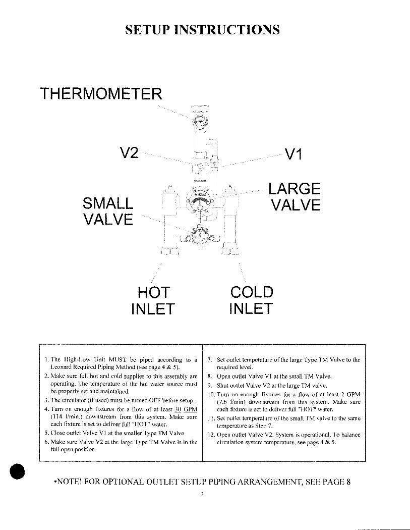
SETUP INSTRUCTIONS
THERMOMETER
V2
SMALLVALVE
V1
LARGEVALVE
-NOTE! FOR OPTIONAL OUTLET SETUP PIPING ARRANGEMENT, SEE PAGE 8
3•
HOTINLET
1. The High-Low Unit MUST be piped according to aLeonard Required Piping Method (see page 4 & 5).
2. Make sure full hot and cold supplies to this assembly areoperating. The temperature of the hot water source mustbe properly set and maintained.
3. The circulator (if used) must be turned OFF before setup.
4. Tum on enough fixtures for a flow of at least 30 aPM(114 Umin.) downstream from this system. Make sureeach fixture is set to deliver full "HOT" water.
5. Close outlet Valve VI at the smaller Type TM Valve
6. Make sure Valve V2 at the large Type TM Valve is in thefull open position.
COLDINLET
7. Set outlet temperature of the large Type TM Valve to therequired level.
8. Open outlet Valve VI at the small TM Valve.
9. Shut outlet Valve V2 at the large TM valve.
10. Tum on enough fixtures for a flow of at least 2 aPM(7.6 Umin) downstream from this system. Make sureeach fixture is set to deliver full "HOT" water.
11. Set outlet temperature of the small TM valve to the sametemperature as Step 7.
12. Open outlet Valve V2. System is operational. To balancecirculation system temperature, see page 4 & 5.

-------------------_ ---------------------
REQUIRED PIPING METHOD #2
FOR SYSTEMS CIRCULATING 8 GPM OR LESS*(SEE PAGE 5, PIPING METHODS 4 AND 5 FOR HIGHER FLOW SYSTEMS)
HIGH TEMPERATURE FIXTURES
TEMPERED FIXTURES
BALL VALVE FORSETUP (OPTIONAL)
THERMOMETER
AQUASTAT
c
TEMPEREDCIRCULATOR
RETURN
,CHECKVALVE VALVE
HEATTRAP
BALANCINGVALVE
HIGH TEMPERATURE "L.' V""
CHECKVALVE
PROCEDURE TO BALANCE CIRCULATION SYSTEM
1. MAKE SURE NO WATER IS BEING DRAWN IN THE BUILDING. OPEN VALVE # 1APPROXIMATELY HALF WAY AND START CIRCULATOR.
2. OBSERVE TEMPERATURE UNTIL IT STABILIZES.
3. CLOSE VALVE # 1 SLIGHTLY IF TEMPERATURE IS TOO HOT, OR OPEN ITSLIGHTLY IF TEMPERATURE IS TOO COLD. ALLOW TEMPERATURE TOSTABILIZE, REPEAT UNTIL DESIRED CIRCULATION TEMPERATURE IS SET.
REMEMBER! THIS IS A CONTROL DEVICE WHICH MUST BE CLEANED ANDMAINTAINED ON A REGULAR BASIS (SEE MAINTENANCE GUIDE ANDRECORD, MGR-IOO).
4
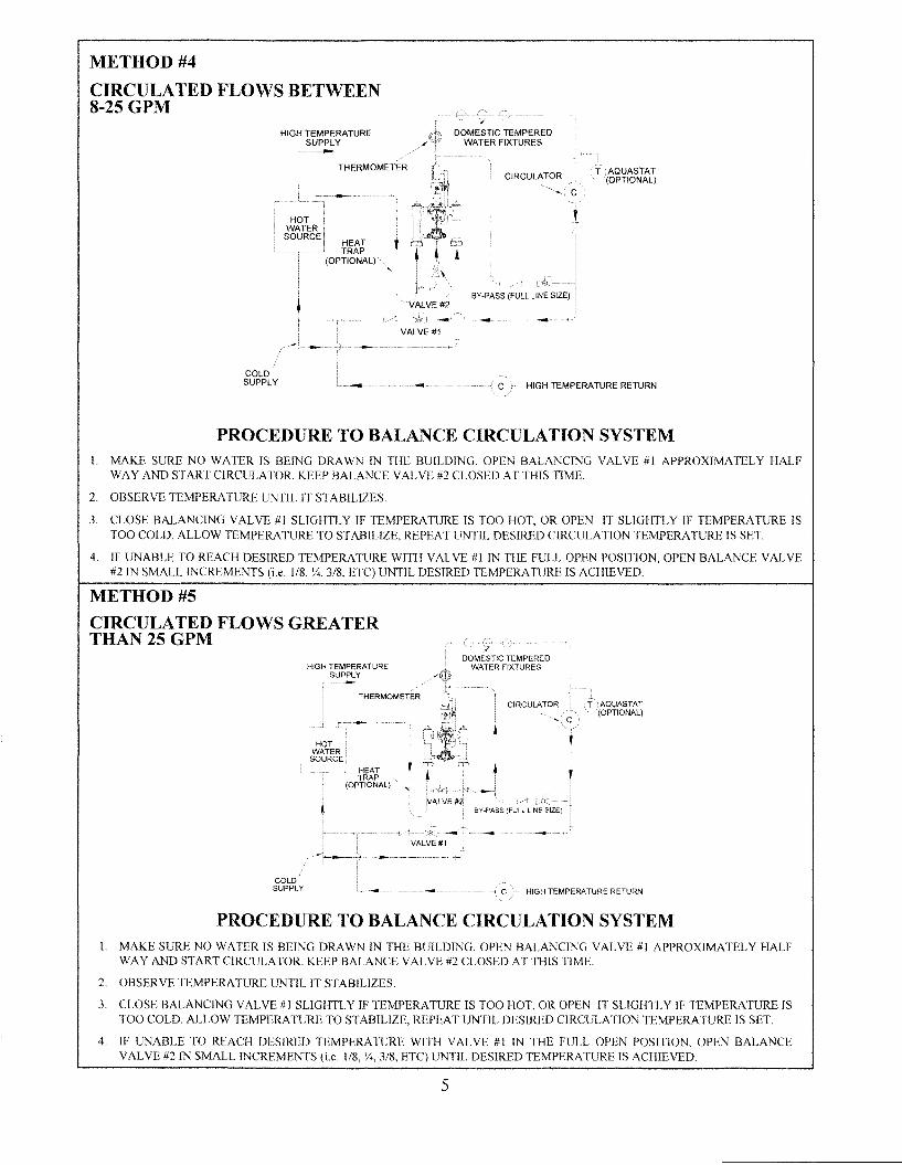
METHOD #4
CIRCULATED FLOWS BETWEEN8-25 GPM
C
CIRCULATOR
C HIGH TEMPERATURE RETURN
DOMESTIC TEMPEREDWATER FIXTURES
,HEATTRAP
(OPTIONAL)
HOTWATER
SOURCE
HIGH TEMPERATURESUPPLY
COLDSUPPLY
PROCEDURE TO BALANCE CIRCULATION SYSTEMI. MAKE SURE NO WATER IS BEING DRAWN IN THE BUILDING. OPEN BALANCING VALVE #1 APPROXIMATELY HALF
WA Y AND START CIRCULATOR. KEEP BALANCE VALVE #2 CLOSED AT THIS TIME.
2. OBSERVE TEMPERATURE UNTIL IT STABILIZES.
3. CLOSE BALANCING VALVE #1 SLIGHTLY IF TEMPERATURE IS TOO HOT, OR OPEN IT SLIGHTLY IF TEMPERATURE ISTOO COLD. ALLOW TEMPERATURE TO STABILIZE, REPEAT UNTIL DESIRED CIRCULATION TEMPERATURE IS SET.
4. IF UNABLE TO REACH DESIRED TEMPERATURE WITH VALVE #1 IN THE FULL OPEN POSITION, OPEN BALANCE VALVE#2 IN SMALL INCREMENTS (i.e. 1/8, v., 3/8, ETC) UNTIL DESIRED TEMPERATURE IS ACHIEVED.
METHOD #5
CIRCULATED FLOWS GREATERTHAN25GPM
HIGH TEMPERATURESUPPLY
DOMESTIC TEMPEREDWATER FIXTURES
C HIGH TEMPERATURE RETURN
PROCEDURE TO BALANCE CIRCULATION SYSTEMI. MAKE SURE NO WATER IS BEING DRAWN IN THE BUILDING. OPEN BALANCING VALVE #1 APPROXIMATELY HALF
WAY AND START CIRCULATOR. KEEP BALANCE VALVE #2 CLOSED AT THIS TIME.
2. OBSERVE TEMPERATURE UNTIL IT STABILIZES.
3. CLOSE BALANCING VALVE #I SLIGHTLY IF TEMPERATURE IS TOO HOT, OR OPEN IT SLIGHTLY IF TEMPERATURE ISTOO COLD. ALLOW TEMPERATURE TO STABILIZE, REPEAT UNTIL DESIRED CIRCULATION TEMPERATURE IS SET.
4. IF UNABLE TO REACH DESIRED TEMPERATURE WITH VALVE #1 IN THE FULL OPEN POSITION, OPEN BALANCEVALVE #2 IN SMALL INCREMENTS (i.e. 1/8, ';4, 3/8, ETC) UNTIL DESIRED TEMPERATURE IS ACHIEVED.
5

INSTRUCTIONS FOR SERVICINGLARGER TM2020B VALVE
INSTRUCTIONS FOR SERVICINGSMALLER TM2020B VALVE
M20-2CCOVER
SCREWS
l TR SET SCREW
POINTER
TEMPERATUREADjUSTING SCREW
6. To clean thermostat group, remove coil sleeve stud and takeoff thermostat group.
7. Clean in a non-corrosive cleaning solution.
8. When reassembling, make sure driving ball of thermostatgroup engages the ball socket of the port sleeve assembly.
1. Loosen LTR set set screw.
2. Remove pointer screw, and pointer.
3. Turn otf hot and cold supplies at screwdriver checkstops.Remove M20-2C cover screws to release cover andthermostatic control assembly.
4. To remove bridge assembly, TM28-1-8B, remove pointerrod nut (MU-1 OB) and pull bridge assembly off control rod.
5. To clean submerge bridge assembly in clean water or noncorrosive cleaning solution. DO NOT USE ABRASIVES!Be certain thimble moves freely on port sleeve. Note!Driving ball on thimble must engage coil bracket inassembling.
TM-28-1-8BBRIDGE ASSY
@MU-10B
POINTER ROD NUT
6. To disassemble bridge assembly, see drawing next page(remove TM25-3A holder nuts with screwdriver in slotsprovided).
7. To clean thermostat coil, remove retaining ring and stop,loosen gland nut. Push rod through cover. Be careful not topull coil out of shape.
THIMBLE
PORTSLEEVENUT
PORTSLEEVE
1. Loosen LTR set screw.
2. Remove snap cap, screw and washer, friction spring andpointer.
3. Tum off hot and cold supplies at checkstops. Remove TM-16cover screws to release cover and thermostatic controlassembly.
4. To clean port sleeve assembly, (the thimble must move freelyon the port sleeve): unscrew the check nut as far as it will go,then screw the port sleeve nut into the base. The port sleeveand thimble may be lined out. SEE DWG BELOW
5. Clean in a non-corrosive cleaning solution. DO NOT USEABRASIVES! The port sleeve should be reassembled in thevalve.
TROUBLESHOOTING INSTRUCTIONSNote: Provide serial number when ordering parts for each valve!
LARGE VALVE SMALL VALVE
PACKING & GASKETS I. Leaks at stem. Repair Kit # 1/200Y Repair Kit # 1/26 (Packings &
2. Leak between valve cover and base. Gaskets)
PORT SLEEVE/BRIDGE 3. Valve delivers either all hot or all cold water. or Repair Kit # Rl200N Repair Kit #Rl28 (Rebuilding
ASSEMBLY will not mix consistently. Kit) or TM28-1-8B BridgeAssembly
THERMOSTAT 4. After cleaning or replacing port sleeve/ bridge Repair Kit # Rl200N Repair Kit #R/28 (Rebuilding
GROUP assembly, valve performance is not consistent. Kit) or TM-28-G2Thermostat Group
CHECKSTOPS 5. Hot water by-pass into cold line(or cold into hot). Repair Kit #2/200Y Repair Kit #41M20 (Checkstop
6. Supplies cannot be shut off completely. Supplies Kit)
leak at checkstop bonnets.
6

LARGE TM VALVE PARTS
TM-16DIALPLATE
MU-SAO'RING (2)
TM-3/200
PORT SLEEVE NUTASSY
PORT SLEEVEASSY
TM-28A
POINTER ROD
TGM-2/125THERMOSTAT GROUP
TM-8COIL SLEEVESTUD
TM-15B/125COVER
30FRICTIONSPRING
TM-25DSTOP
FLANGE PACKING
TM-16COVER
SCREWS
TM-16ADIAL
PLATE
TM-25CPOINTER
57-LSNAP CAP
TM-29/29APOINTER SCREW
WIWASHER
CHECKSTOP PARTS REPAIR KITS
4728CAP WASHER"
TGM-2/125THERMOSTATGROUP
UPPER STEM O'RING (4)
TM-3/200PORT SLEEVENUT ASSY.
KIT 1/200Y * PACKINGS &GASKETSMU-5A 4724
O'RING " SCREEN ..
4733LOVVER STEM
&PACKING ..
4728CAP WASHER
4727UPPER STEM
313O'RINGS(2)
4742YELLOWSPRING
4733LOVVER STEM &
PACKING/O'RING
'4707SWIVEL NUT '4704
SWIVEL
(' IF APPLICABLE)
2EA:313
STEM O:RING (4)LOCK-TYPE
POINTER TM-36SET 4733
LOVVER STEM& PACKING
4742YELLOWSPRING
4724SCREEN 4728
CAP WASHER
REMEMBER! THIS IS A CONTROL DEVICE WHICH MUST BE CLEANED ANDMAINTAINED ON A REGULAR BASIS (SEE MAINTENANCE GUIDE AND RECORD)
NOTE: AFTER INSTALLING NEW PARTS IT WILL BE NECESSARY TO RESET THEADJUSTABLE HIGH TEMPERATURE LIMIT STOP ON EACH VALVE (SEE PAGE 2).
7

SMALL TM VALVE PARTS
6910l TR SET SCREW
7520POINTER SCREW
03307DIAL PLATE
57-0 RFGLAND NUT
M20-1 C RFICP
COVER M20~C
COVERGASKET
TM2B-G2THERMOSTAT GROUP
MlJ.4CGLAND PACKING
(2 REO'D)
MU-l0BPOINTER ROD NUT
(\\--/
TM25-3BP .S. PACKING
(2 REO'D)
TM-28-1-8BB RIDGE ASSEMBLY
TM-25~A
P.S. HOLDER NUT(2 REO'D)
TM-28-6BHOl DE R NUT ORiNG
(2 REO'D)
TM25-<iBRIDGE
TM25-3P .S. HOLDER
(2TGM-lI2B
PORT SLEEVEASSEMBLY
CHECKSTOP PARTS REPAIR KITS
M20-6AlOWER STEM
& PKG. (2 EACH)MU-5AO'RING(2 EACH)
TM-28-6BHOLDER NUT
O'RING (2 EACH)
tvvl
M20-9A(2 EACH)
CHECK SPRING
KIT 1/26 PACKINGS & GASKETS
M20-3ABONNETPKG.
(2 EACH)
MU--4CGLANDPKG.
(2 EACH)
M20-2A RFCHECK BONNET
MU-4ARFUPPER STEMAND PACKING
MU-5AUPPERSTEM PKG.
IvV
M20-9ACHECK SPRING
lOWERSTEM & PACKING
M2D-3A BONNETPACKING
CHECKSTOPS
KIT R/28 REBUILDING KIT
REMEMBER! THIS IS A CONTROL DEVICEWHICH MUST BE CLEANED ANDMAINTAINED ON A REGULAR BASIS (SEEMAINTENANCE GUIDE AND RECORD)
NOTE: AFTER INSTALLING NEW PARTS ITWILL BE NECESSARY TO RESET THEADJUSTABLE HIGH TEMPERATURE LIMITSTOP ON EACH VALVB (SEE PAGE 2).
2 EACH:
M20-6AlOWER STEM
& PACKING
MU-5A UPPERSTEMO'RING
M20-9A
CHECK SPRING
TM-28-1-12B
THERMOSTATICCONTROL ASSEMBLY
M20-3ABONNETPKG.
8
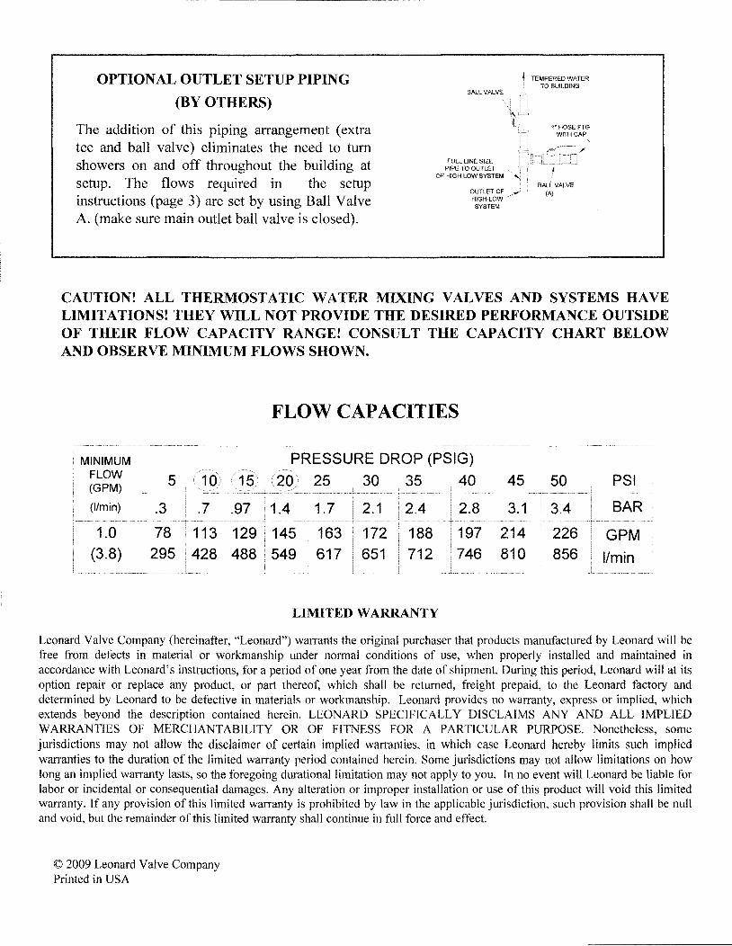
OPTIONAL OUTLET SETUP PIPING
(BY OTHERS)
The addition of this piping arrangement (extratee and ball valve) eliminates the need to tumshowers on and off throughout the building atsetup. The flows required in the setupinstructions (page 3) are set by using Ball ValveA. (make sure main outlet ball valve is closed).
BALL VALVE
FULL LINE SIZEPIPE TO OUTLET
OF HIGH LOW SYSTEM
OUTLET OFHIGH-LOWSYSTEM
, TEMPERED WATERTO BUILDING
CAUTION! ALL THERMOSTATIC WATER MIXING VALVES AND SYSTEMS HAVELIMITATIONS! THEY WILL NOT PROVIDE THE DESIRED PERFORMANCE OUTSIDEOF THEIR FLOW CAPACITY RANGE! CONSULT THE CAPACITY CHART BELOWAND OBSERVE MINIMUM FLOWS SHOWN.
FLOW CAPACITIES
MINIMUMFLOW(GPM)
(I/min)
1.0(3.8)
PRESSURE DROP (PSIG)
25 30 35 40
1.7 2.1 2.4
163 172 188617 651 712
LIMITED WARRANTY
45 50
3.4
226856
PSI
BAR
GPM
I/min
Leonard Valve Company (hereinafter, "Leonard") warrants the original purchaser that products manufactured by Leonard will befree from defects in material or workmanship under normal conditions of use, when properly installed and maintained inaccordance with Leonard's instructions, for a period of one year from the date of shipment. During this period, Leonard will at itsoption repair or replace any product, or part thereof, which shall be returned, freight prepaid, to the Leonard factory anddetermined by Leonard to be defective in materials or workmanship. Leonard provides no warranty, express or implied, whichextends beyond the description contained herein. LEONARD SPECIFICALLY DISCLAIMS ANY AND ALL IMPLIEDWARRANTIES OF MERCHANTABILITY OR OF FITNESS FOR A PARTICULAR PURPOSE. Nonetheless, somejurisdictions may not allow the disclaimer of certain implied warranties, in which case Leonard hereby limits such impliedwarranties to the duration of the limited warranty period contained herein. Some jurisdictions may not allow limitations on howlong an implied warranty lasts, so the foregoing durational limitation may not apply to you. In no event will Leonard be liable forlabor or incidental or consequential damages. Any alteration or improper installation or use of this product will void this limitedwarranty. If any provision of this limited warranty is prohibited by law in the applicable jurisdiction, such provision shall be nulland void, but the remainder of this limited warranty shall continue in full force and effect.
© 2009 Leonard Valve CompanyPrinted in USA