
Ta b l e of Contents - Locostlocost7.info/files/other/auto_aluminum.pdf · Rolling Meadows,IL 60008...
25
1.0 Introduction 2 2.0 Characteristics of Aluminum 3 3.0 Applications for Aluminum 6 4.0 Metalworking 10 5.0 Joining Methods 13 6.0 Refinishing 21 7.0 Glossary 23 Publication AT 4 Practices for the Repair of Automotive Sheet Aluminum T a b l e of Contents Copyright 1998 The Aluminum Association
Transcript of Ta b l e of Contents - Locostlocost7.info/files/other/auto_aluminum.pdf · Rolling Meadows,IL 60008...
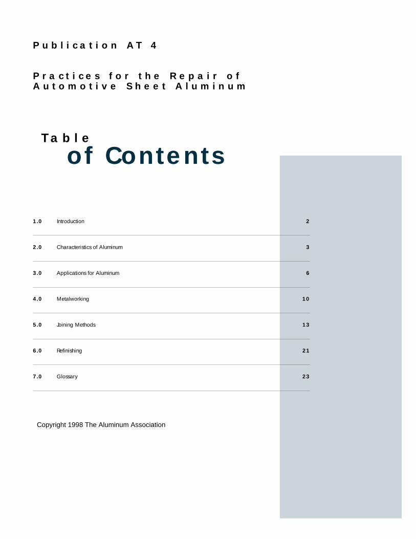
1.0 Introduction 2
2.0 Characteristics of Aluminum 3
3.0 Applications for Aluminum 6
4.0 Metalworking 10
5.0 Joining Methods 13
6.0 Refinishing 21
7.0 Glossary 23
P u b l i c a t i o n AT 4
P r a c t i c e s f o r t h e R e p a i r o fA u t o m o t i v e S h e e t A l u m i n u m
Ta b l e
of Contents
Copyright 1998 The Aluminum Association

One of the inevitable consequencesof the use of automobiles is thatfrom time to time accidents willcause damage to a vehicle’s body.Knowing how to appraise and repaircollision damage correctly is a majorresponsibility of the collision repairindustry. Over the years, as newmaterials have been introduced tothe car body, repair procedures havebeen developed and accepted by thecollision repair industry. Examplesinclude FRP body panels and highstrength steels. Aluminum is takingits place as an accepted body paneland structural material and it is thepurpose of this publication to high-light those practices that may beused for effective repair of aluminumby describing some of the features ofaluminum that are important forrepair. This guide will not teach
2
1.0Introduction
repair. For an introduction to thatwe, The Aluminum Association, rec-ommend the course “AluminumAlloy Repair, Replacement, andWelding” offered by I-CAR. Allrepair personnel should also seekhands on training to develop profi-ciency.
Steel has been the dominantmaterial for vehicle bodies and tothis point most repair practices havefocused on it. In many respects prac-tices for aluminum repairs are similarto those for steel but there areimportant distinctions to be made.Often the similarities lead to achoice of practices and this publica-tion will focus on those preferred bythe aluminum industry. There issometimes a temptation to “makedo” with borrowed practices andwhile we recognize that sometimesthis works, it is always better to usepractices specific to aluminum.
Since large scale use of alu-minum in vehicles is relatively newthere is a tendency to assume that itis more difficult to use, both in man-ufacture and repair. Auto manufac-turers are coming to realize that alu-minum is practical and economicalto manufacture and that the samewill be true of repair. There is a cer-tain amount of art to metal working
and it requires experience to perfectthat art.The aluminum industry hasan informal motto that working alu-minum is “different, not difficult”and it is hoped this publication willhelp show the accuracy of that state-ment.
The Aluminum Associationacknowledges the pioneering work indeveloping repair techniques done bythe auto manufacturers, the Inter-Industry Conference on Auto Repair (I-CAR)*, and many others from theauto insurance and repair equipmentsupply industries. In the preparationof this guide, much of the materialhas also been drawn from otherrelated Aluminum Association pub-lications.
*I-CAR can be contacted at:3701 Algonquin Rd.Suite 400 Rolling Meadows,IL 600081/800-ICAR-USA-T1/800-590-1215-F

Aluminum has many characteris-tics that make it suitable for a varietyof automotive applications. It is:
Strong - the entire vehicle body canbe aluminum
Durable - good resistance to corro-sion and fatigue
Conductive - both thermal and elec-trical — for efficient engine andelectrical components
Nonmagnetic - useful in electronicsNontoxic - important in any materi-
al used in carsAbundant - adequate supply world-
wide Recyclable - saves energy, benefits
the environmentWorkable - uses well understood
metalworking processesAvailable - aluminum’s many prod-
uct forms offer design flexibilit y
and above all, its low density andhigh strength means that aluminumparts weigh much less than tradi-tional materials such as steel, copper,brass and automotive plastics.
3
2.0Characteristics ofAluminum
It is the overall value of alu-minum that makes it suitable for somany kinds of vehicle applicationsbut it is the weight characteristicthat stands out. In the 1970’s a seriesof fuel crises made it clear thatAmerica could no longer be insensi-tive to the energy impact of theautomobile. Fuel use is directlyrelated to weight and over the yearsgoals for fuel economy have beenraised and the auto manufacturershave responded with many innova-tions to reduce fuel consumptionwhile providing the other character-istics their customers want. Simplymaking a little car with an anemicengine no longer suffices and theincreasing addition of safety featuresand other improvements have com-bined to make it necessary to findadditional avenues to keep weight inline. Aluminum has come forwardas a major solution to the weightproblem. In all, a body-in-whitestructure of aluminum will have aprimary weight savings of 45% to50% over conventional steel con-struction. In the Ford Taurus/Sable-based aluminum intensive vehicles(AIV) this meant a total vehicleweight reduction of 11.6% withoutsecondary weight savings.
Additional savings are foundwherever aluminum is used andleads to still more savings, referredto as secondary savings, through the
ability to downsize other compo-nents, such as the suspension andengine.
Aluminum is produced frombauxite ore which is recovered fromopen pit mines.The ore is processedthrough a multi-step process collec-tively called the Bayer process toproduce alumina (Al2O3). This inturn is smelted into metallic alu-minum in the Hall/Heroult process.In this process the alumina is placedin carbon lined reduction cells,known as pots. It is dissolved insodium-aluminum fluoride, calledcryolite, and an electric current inpassed through the mixture.Thiscurrent reduces the alumina into alu-minum, with the release of carbondioxide.The molten aluminum set-tles to the bottom of the pot and isdrawn off to solidify into unalloyedingot, also known as pig. The alu-minum thus produced is known asprimary aluminum. Roughly one-third of the North American alu-minum supply is primary metal.Another third is imported metal andthe final third is produced from recy-cled aluminum. In automobiles sub-stantial use is made of recycled alu-minum, especially in powertrainapplications.
Aluminum is not, however, usedin its pure form for vehicles. Ratherit is alloyed with other elements suit-ed to the product form it will beused in to produce a desired set ofphysical properties or characteristicsas, for example, corrosion resistance.The three broad classes of aluminum
4
products are ingot, wrought prod-ucts, and castings. Ingot is cast fromholding furnaces, in which alloying iscarried out, and is the starting mater-ial for both cast and wrought prod-ucts. Casting is employed to producenet shape products in whichmechanical properties are determinedby the alloying elements and thermaltreatments after casting. Wroughtproducts are defined by the fact thatthey are given some mechanicaldeformation in production. Wroughtproducts are sheet, plate, foil, extru-sions, tube, rod, bar and forgings.The collision repair technician willbe dealing with sheet products forexterior panels, but vehicles withother aluminum applications willpresent the technician with a varietyof product forms, especially extru-sions and castings. The AluminumAssociation’s publication Aluminumfor Automotive Body Sheet PanelsAT3gives a thorough discussion of thesheet alloys used.This publicationwill utilize some of that informationbecause repairs depend upon alloysand their characteristics.
Wrought alloys are described by afour digit numerical designator (seeSection 3).The first digit indicates afamily of alloys having the sameprincipal alloying element and theother three define the specific alloy.The families also fall into one of twogroups:
• heat-treatable (HT) which gaintheir mechanical properties bythermal processes; and,
• non-heat-treatable (NHT) whichgain their mechanical propertiesfrom cold working.
There are many variations to theprocessing of any given alloy and thesubject is complex. For the repairtechnician, it is only necessary toknow that these two groups wil lbehave differently in some repairprocesses. Casting alloys employ adifferent numbering system using athree digit number.
Each alloy, cast or wrought, issupplied in various tempers, whichdictate the level of mechanical prop-erties of the material.The temper isidentified by a suffix to the alloynumber. For heat-treatable alloys thesuffix begins with a “T”, as in 6111-T4. For non-heat-treatable alloys thesuffix begins with an “H”, as in 3003-H14. In both groups the suffix “0”indicates the annealed or, as it issometimes called, “soft” condition.For automotive applications, heat-treated sheet is normally supplied inthe -T4 temper. The next sectionlists alloys that may be encounteredand their typical automotive applica-tions, with the more current alloysunderlined.The collision repair tech-nician should know the alloys beingworked with because that can affectthe repair, as for instance in theselection of weld wire, if welding isto be employed.
For the repair of body panels,dent resistance and amount of deflec-tion under load are two of the princi-
pal criteria. Dent resistance is basedon many factors, the shape of thepart and its support being of primaryimportance. Given the same design,the factors affecting dent resistanceare yield strength and thickness andin comparing steel and aluminum thegreater thickness of the aluminumpanel can more than compensate forits lower yield strength. If the yieldstrength of the aluminum and thesteel are the same, the dent resistancewill be equivalent for the same thick-ness.The deflection under load, orstiffness, of a panel is not influencedby the strength of the material but iscontrolled by the material ’s modulusof elasticity ( Young’s Modulus) andits thickness. Compared to steel, alu-minum is at a disadvantage becauseits modulus of elasticity is one-thirdthat of steel and therefore may seemto be less sturdy. However, the greaterthickness of the aluminum quicklycompensates for this because panelbending stiffness increases with thethird power of thickness. In practice,however, it is usually beneficial toreduce the spacing of the supportingstructure for an aluminum design inorder to achieve the required resis-tance to deflection.
Later in this manual the use ofheat in making repairs is discussed.The following table taken from TheAluminum Association publicationAT3 shows the properties of selectedsheet alloys as supplied and after heatand cold work. It should be notedthat, when the materials are heated inthe typical OEM paint bake cycle,the strength of the non-heat-treat-able alloys (5xxx) are not affected but,when stretching (as in panel forming)

5
is included, the strength goes up.The other alloys show mixed resultswith the 6xxx alloys gaining by bothheating and stretching. Alloys fromthe 6xxx group are being more andmore frequently specified for exteriorpanels because of this strengtheningcapability and because of their goodoverall corrosion resistance.
Corrosion resistance is one of thevaluable characteristics of aluminumbut aspects of it seem to be amongthe most “worried about” factors indeciding to use aluminum, not sur-prising in view of the harsh environ-mental conditions many vehicles canbe expected to face.The subject iscomplex but there are certain princi-ples the repair person should knowabout. Aluminum exposed to airinstantly reacts with it to form a thincoherent oxide film. This oxide filmor layer effectively seals off the alu-minum from further contact with air,thereby providing aluminum’s highcorrosion resistance.
This film will get thicker, at adeclining rate, over a period ofmonths (assuming no other surfacecoatings) and even though it shouldbe removed before some proceduresit will reform immediately. Becauseof that the collision repair technicianneed not fear that repair will impairthe inherent corrosion resistance ofthe aluminum.
In the presence of other metals,aluminum may be subject to galvanicaction, an electrolytic reaction whereone metal is anodic to another andwill preferentially corrode to protectthe other in the presence of a severeenvironment.This reaction is some-what dependent on the alloy typeand some alloys have better corro-sion resistance than others in equiva-lent exposure. In vehicles, aluminumis anodic to most metals except mag-
nesium and zinc.This means ofcourse that if aluminum is connectedto the most common material, steel,without proper preventive steps, thealuminum may suffer corrosion byprotecting the steel electrochemical-ly. In manufacturing this potentialfor corrosion is eliminated by usingcoated fasteners, appropriate coat-ings and sealants, and by isolatingthe metals by using non-metallicinsulation such as gaskets and wash-ers between parts.The repair techni-cian must insure that all such pre-ventive steps are maintained afterthe repair. The manufacturers’ ser-vice manuals specify what should beused.
In practice, most aluminum pan-els are painted for appearance. If animproperly applied coating is dam-aged, a type of corrosion called fili-form corrosion can occur betweenthe coating and the surface of thealuminum. Correct finishing istherefore an important part of therepair process.
TABLE 2 .0 TYPICAL PROPERT I ES OF ALUMINUM BODY SHEET ALLOY S FOLLOWING A S I M U L ATE D PAINT BAKE CYCLE ( 1 )
Original Material Paint Bake Only (No Prior Stretch) 2% Stretch + Paint Bake
Ultimate Tensile Elongation Ultimate Tensile Elongation Ultimate Tensile ElongationTensile Yield in 50mm Tensile Yield in 50mm Tensile Yield in 50mm
Alloy & Strength Strength or 2 in Strength Strength or 2 in Strength Strength or 2 in
Temper MPa (ksi) MPa (ksi) % MPa (ksi) MPa (ksi) % MPa (ksi) MPa (ksi) %
2008-T4 250 (36) 125 (18) 28 255 (37) 145 (21) 26 260 (38) 165 (24) 232010-T4 240 (35) 130 (19) 25 235 (34) 130 (19) 26 250 (36) 170 (25) 222036-T4 340 (49) 195 (28) 24 315 (46) 180 (26) 28 330 (48) 195 (28) 255182-0 275 (40) 130 (19) 21 275 (40) 130 (19) 21 275 (40) 145 (21) 195454-0 250 (36) 115 (17) 22 250 (36) 115 (17) 22 240 (35) 130 (19) 215754-0 220 (32) 100 (14) 26 220 (32) 95 (14) 26 220 (32) 110 (16) 256009-T4 220 (32) 125 (18) 25 275 (40) 180 (20) 22 285 (41) 195 (28) 206111-T4 280 (42) 150 (22) 26 310 (45) 200 (29) 24 315 (46) 240 (30) 226022 257 (37) 148 (22) 26 (45) (25) 26 (41) (31) 24
(1) 30 min at 177°C (350°F).
6
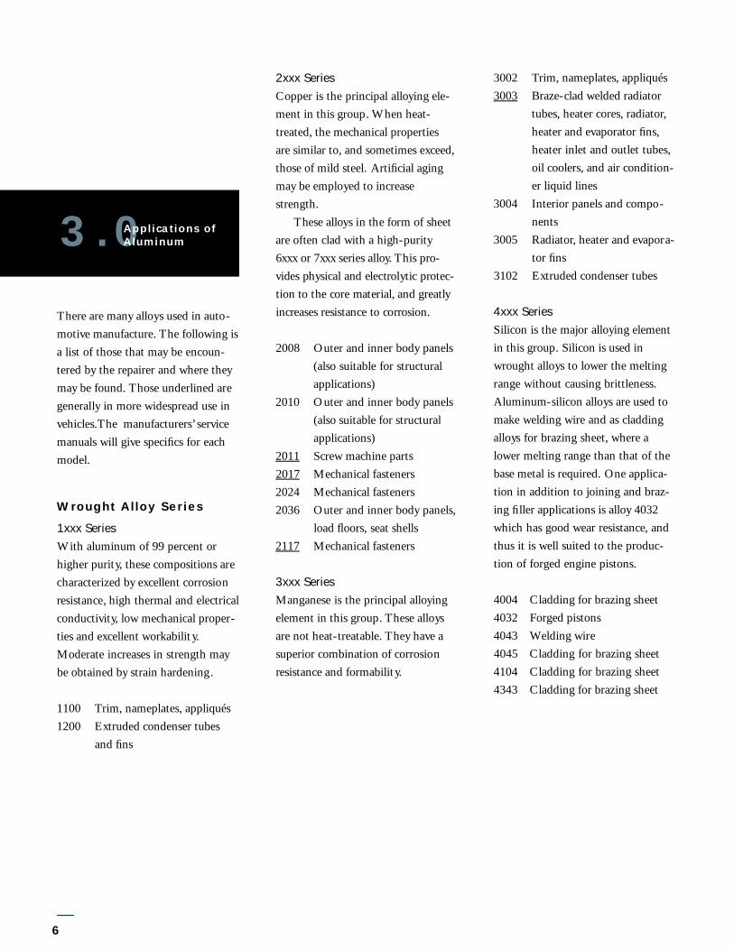
There are many alloys used in auto-motive manufacture. The following isa list of those that may be encoun-tered by the repairer and where theymay be found. Those underlined aregenerally in more widespread use invehicles.The manufacturers’ servicemanuals will give specifics for eachmodel.
Wrought Alloy Series
1xxx SeriesWith aluminum of 99 percent orhigher purity, these compositions arecharacterized by excellent corrosionresistance, high thermal and electricalconductivity, low mechanical proper-ties and excellent workability.Moderate increases in strength maybe obtained by strain hardening.
1100 Trim, nameplates, appliqués1200 Extruded condenser tubes
and fins
2xxx SeriesCopper is the principal alloying ele-ment in this group. When heat-treated, the mechanical propertiesare similar to, and sometimes exceed,those of mild steel. Artificial agingmay be employed to increasestrength.
These all oys in the form of sheeta re often clad with a high-puri ty6xxx or 7xxx series all oy. This pro-vides phys i cal and electro lytic pro t e c-t i on to the core materi a l , and gre a t lyi n c reases resistance to corro s i on .
2008 Outer and inner body panels(also suitable for structuralapplications)
2010 Outer and inner body panels(also suitable for structuralapplications)
2011 Screw machine parts2017 Mechanical fasteners2024 Mechanical fasteners2036 Outer and inner body panels,
load floors, seat shells 2117 Mechanical fasteners
3xxx SeriesManganese is the principal alloyingelement in this group. These alloysare not heat-treatable. They have asuperior combination of corrosionresistance and formability.
3002 Trim, nameplates, appliqués3003 Braze-clad welded radiator
tubes, heater cores, radiator,heater and evaporator fins,heater inlet and outlet tubes,oil coolers, and air condition-er liquid lines
3004 Interior panels and compo-nents
3005 Radiator, heater and evapora-tor fins
3102 Extruded condenser tubes
4xxx SeriesSilicon is the major alloying elementin this group. Silicon is used inwrought alloys to lower the meltingrange without causing brittleness.Aluminum-silicon alloys are used tomake welding wire and as claddingalloys for brazing sheet, where alower melting range than that of thebase metal is required. One applica-tion in addition to joining and braz-ing filler applications is alloy 4032which has good wear resistance, andthus it is well suited to the produc-tion of forged engine pistons.
4004 Cladding for brazing sheet4032 Forged pistons4043 Welding wire4045 Cladding for brazing sheet4104 Cladding for brazing sheet4343 Cladding for brazing sheet
3.0Applications ofAluminum

7
5xxx SeriesMagnesium is one of the most effec-tive and widely used alloying ele-ments for aluminum, and is the prin-cipal element in the 5xxx seriesalloys. When it is used as the majoralloying element or combined withmanganese, the result is a moderate-to high-strength, non-heat-treatablealloy. Alloys in this series are readilyweldable and have excellent resis-tance to corrosion, even in marineapplications.
5005 Trim, nameplates, appliqués5052 Interior panels and compo-
nents, truck bumpers andbody panels
5182 Inner body panels, splashguards, heat shields, aircleaner trays and covers,structural and weldable parts,load floors (sheet)
5252 Trim5454 Various components, wheels,
engine accessory brackets andmounts, welded structures(i.e. dump bodies, tanktrucks, trailer tanks)
5457 Trim 5657 Trim5754 Inner body panels, splash
guards, heat shields, aircleaner trays and covers,structural and weldable parts,load floors (sheet), body-in-white structures
6xxx SeriesAlloys in this group utilize magne-sium and silicon in various propor-tions to form magnesium silicide,which makes them heat-treatable. Amajor alloy in this series is 6061, oneof the most versatile general purposeheat-treatable structural alloys. Themagnesium-silicon (or magnesium-silicide) alloys possess good formabil-ity and corrosion resistance with highstrength.
6009 Outer and inner body panels,load floors, bumper face bars,bumpers reinforcements,structural and weldable parts,seat shells
6010 Outer and inner body panels,seat shells and tracks
6016 Outer and inner body panels6022 Outer and inner body panels6053 Mechanical fasteners6061 Body components (extruded),
brackets (extruded andsheet), suspension parts(forgings), driveshafts(tubes), driveshaft yokes(impacts and forgings),sparetire carrier parts (extruded),bumper reinforcements,mechanical fasteners, brakecylinders (extruded), wheels(sheet), fuel delivery systems
6063 Body components (extruded)6082 General structural, brake
housings6111 Body panels6262 Brake housings, brake pis-
tons, general screw machineparts (anodized)
6463 Luggage racks, air deflectors
7xxx SeriesZinc is the principal alloying ele-ment in this group. When it is com-bined with smaller percentages ofmagnesium and, in some cases cop-per, it results in heat-treatable alloysof very high strength.
7003 Seat tracks, bumper rein-forcements
7004 Seat tracks, bumper rein-forcements
7021 Bumper face bars, brackets(sheet), bumper face bars(bright), bumper face bars(bright anodized), bumperreinforcements
7072 Condenser and radiator fins7116 Headrest bars7129 Bumper face bars, bumper
reinforcements, headrest bars(extruded), seat track
Casting Alloys
Aluminum alloy castings which forthe most part, are aluminum-siliconalloys, can be produced by virtuallyall casting processes in a very largerange of compositions possessing awide variety of useful engineeringproperties. The choice of a specificcasting alloy depends on the chosencasting process (which include: sand,
8
permanent mold, die, lost foam, orsqueeze), the product design, therequired properties of the productand other relevant factors.
Alloy Typical Applications319.0 Manifolds, cylinder heads,
blocks, internal engine parts332.0 Pistons356.0 Cylinder heads, manifoldsA 3 5 6 . 0 WheelsA 3 8 0 . 0 Blocks, transmission hous-
ings/parts, fuel meteringdevices
383.0 Brackets, housings, internalengine parts, steering gears
B 3 9 0 . 0 High-wear applications suchas ring gears and internaltransmission parts
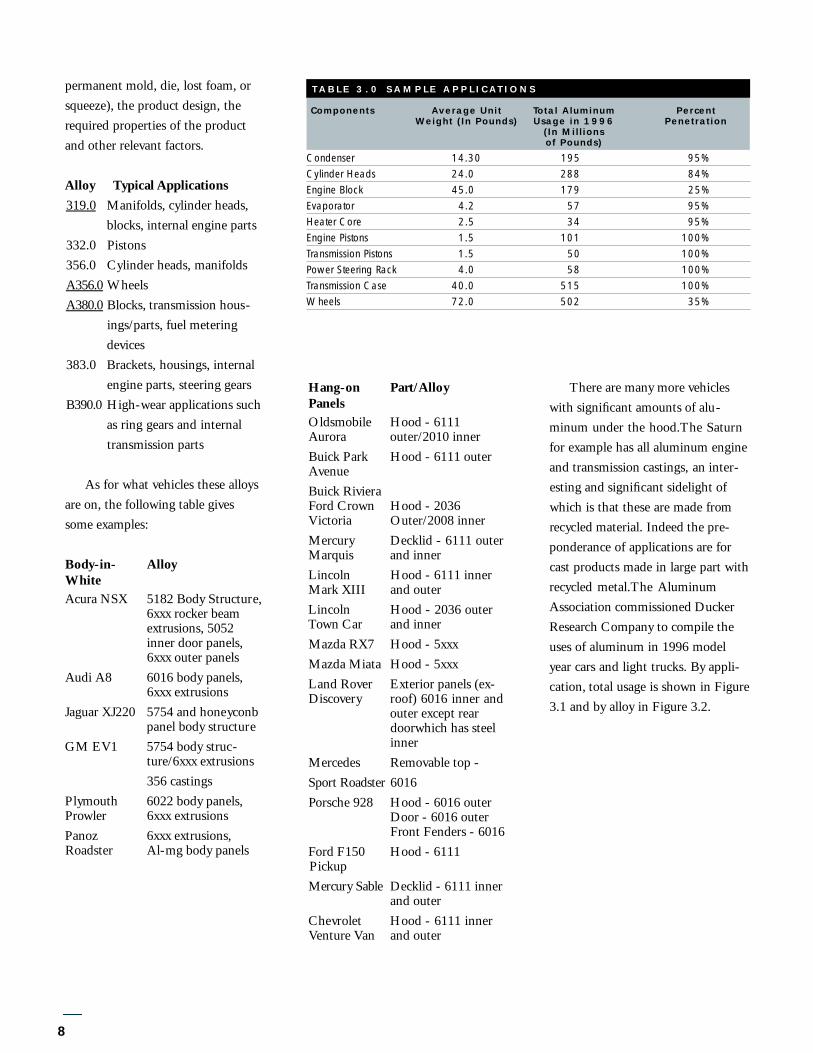
As for what vehicles these alloysare on, the following table givessome examples:
Body-in- AlloyWhiteAcura NSX 5182 Body Structure,
6xxx rocker beamextrusions, 5052inner door panels,6xxx outer panels
Audi A8 6016 body panels,6xxx extrusions
Jaguar XJ220 5754 and honeyconbpanel body structure
GM EV1 5754 body struc-ture/6xxx extrusions356 castings
Plymouth 6022 body panels,Prowler 6xxx extrusionsPanoz 6xxx extrusions,Roadster Al-mg body panels
Hang-on Part/AlloyPanelsOldsmobile Hood - 6111 Aurora outer/2010 innerBuick Park Hood - 6111 outerAvenueBuick RivieraFord Crown Hood - 2036 Victoria Outer/2008 innerMercury Decklid - 6111 outer Marquis and innerLincoln Hood - 6111 innerMark XIII and outerLincoln Hood - 2036 outer Town Car and innerMazda RX7 Hood - 5xxxMazda Miata Hood - 5xxxLand Rover Exterior panels (ex-Discovery roof) 6016 inner and
outer except reardoorwhich has steelinner
Mercedes Removable top - Sp o rt Roadster 6016Porsche 928 Hood - 6016 outer
Door - 6016 outerFront Fenders - 6016
Ford F150 Hood - 6111PickupM e rc u ry Sa b l e Decklid - 6111 inner
and outerChevrolet Hood - 6111 inner Venture Van and outer
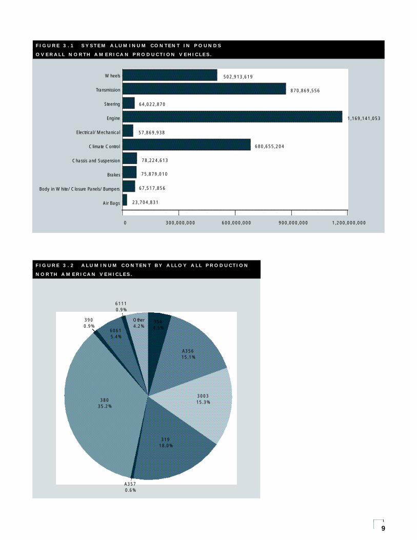
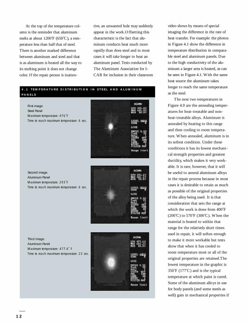
There are many more vehicleswith significant amounts of alu-minum under the hood.The Saturnfor example has all aluminum engineand transmission castings, an inter-esting and significant sidelight ofwhich is that these are made fromrecycled material. Indeed the pre-ponderance of applications are forcast products made in large part withrecycled metal.The AluminumAssociation commissioned DuckerResearch Company to compile theuses of aluminum in 1996 modelyear cars and light trucks. By appli-cation, total usage is shown in Figure3.1 and by alloy in Figure 3.2.
TABLE 3.0 SAMPLE APPLI CAT I O N S
Components Average Unit Total Aluminum Percent Weight (In Pounds) Usage in 1996 Penetration
(In Millions of Pounds)
Condenser 14.30 195 95%Cylinder Heads 24.0 288 84%Engine Block 45.0 179 25%Evaporator 4.2 57 95%Heater Core 2.5 34 95%Engine Pistons 1.5 101 100%Transmission Pistons 1.5 50 100%Power Steering Rack 4.0 58 100%Transmission Case 40.0 515 100%Wheels 72.0 502 35%
9
F IGURE 3.1 S YSTEM ALUMINUM CONTENT IN POUNDS
OVERALL NORTH AMERICAN PRODUCT ION VEHICLES.
Wheels
Transmission
Steering
Engine
Electrical/Mechanical
Climate Control
Chassis and Suspension
Brakes
Body in White/Closure Panels/Bumpers
Air Bags
502,913,619
870,869,556
64,022,870
1 , 1 6 9 , 1 4 1 , 0 5 3
57,869,938
680,655,204
78,224,613
75,879,010
67,517,856
23,704,831
0 300,000,000 600,000,000 900,000,000 1,200,000,000
38035.2%
A3570.6%
31918.0%
300315.3%
A35615.1%
3564.5%
Other4.2%
61110.9%
60615.4%
3900.9%
F IGURE 3. 2 ALUMINUM C ONTENT BY ALLOY ALL PRODUCT ION
N O RTH AMERICAN VE HICLES .

welding, finishing, and even corro-sion. Metal tools such as hammers,dollies, and spoons should havesmooth and polished faces androunded edges so as not to gouge thealuminum. Wood, leather and plasticfaced hammers are generally pre-ferred. Do not use hammers withserrated faces. For wire brushing, usestainless steel brushes and againmaintain the brushes strictly for aluminum.
Cutting
Aluminum sheet is in most casesbest cut using mechanical means andin fact cutting aluminum is more likeworking with wood than with steel.Reciprocating saws and band sawscan be used effectively. Blade toothshape and spacing differ from thoseused for steel and appropriate bladesare available for aluminum. In gener-al, the best results are achieved withhigh blade speeds. Use of the wrongblades and/or too slow speeds cancause the blade to snag in thin sheetfound in auto body work.
An important difference betweenaluminum and steel is that oxy-fuelcutting is not effective on aluminumbecause the oxide film and the alu-minum melt at different tempera-tures and because aluminum con-ducts heat rapidly away from thework area.The result is a ragged cutthat will have to be further trimmed.
10
The processes used for working alu-minum are similar to those used forconventional steel body panels. Thatsaid, there are differences that areimportant for the repair person to beaware of. This chapter will reviewgeneral practices and highlight prac-tices especially applicable to alu-minum. Repair industry safety pre-cautions must always be observed.
Handling
Aluminum has a tendency to scratchor scuff more easily than steel andthat is the first thing the collisionrepair technician needs to keep inmind. Replacement parts will becarefully packaged and they shouldbe treated with care as they areunpacked and brought to the work-place. Aluminum should not beworked on a steel table or on thefloor unless a sheet of plywood or thelike is first put on the table or work-place.
Proper storage is also important.Aluminum gains its good corrosionresistance from the presence of a thindense oxide layer, or film which ispresent from the time the aluminumis exposed to air. This layer is verythin but will thicken over time with
continued exposure.The layer cantrap dirt and moisture which in turnmay affect repair processes such aswelding. Sanding, grinding, etching,etc. are used to remove this layer,although for welding preparationwire brushing is recommended.O ften the question arises as to hows o on after re m oval can processes suchas welding or painting begin. T h e rea re no hard and fast ru l e s , but leavingcleaned aluminum ove rnight if it isw e ll stored and is not subject tom o i s t u re, does not pose a pro b l e m .
When aluminum is stored withthe sheets stacked cl o s e ly togetherm o i s t u re condensing between thesheets can be trapped and over timecause exc e s s i ve oxide buildup ca ll e dwater staining. T h e re f o re, it is re c om-mended that aluminum alw ays bes t o red indoors in a climate con t ro ll e da rea where there are no rapid ch a n g e sin tempera t u re and humidity.
Tools
Tools for working aluminum arebasically the same as those used forworking steel. Using the same set oftools, however, introduces the possi-bility of contaminating the alu-minum with steel particles and wherepossible tools should be kept sepa-rate. In particular sanding discs, cut-ting tools, files and even shop towelsshould not be used interchangeablyon steel and aluminum. Power toolsshould be cleaned off before using onaluminum. All this is done to avoidthe possibility of contaminating thealuminum surface with steel particleswhich could cause problems with
4.0Metalworking

Plasma arc cutting is a suitableprocess for aluminum. It works byheating a gas with a tungsten arc anddirecting the hot plasma through anorifice at high velocity. For thinsheet, as found in vehicle construc-tion, air is the gas and cutting speedsin the range of 200 in./min (85 mm/sec) are achieved. Howeverthe process leaves a heat affectedzone (HAZ) at the cut edge whichmay have to be removed mechanical-ly if the application demands.
Grinding, Sanding, andFiling
For sanding aluminum, use orbital ordual-action sanders with open-coatsanding discs on soft or flexible back-ing pads. Do not use discs coarserthan 80 grit. In general, use onlylight pressure for best results.
Files and stones are used to trimedges and on panels to highlightdamaged areas. Filing should bedone very carefully to avoid gougingthe surface and in fact a dull file ispreferred over a sharp one. Frequentcleaning of the file is necessary toavoid buildup of particles. As notedbefore do not use the same file onboth aluminum and steel. A longsanding board, typically used forsanding filler, effectively highlightshigh spots without removing metal.
11
The Use of Heat
Hammers, dollies, picks, etc. are usedto physically move metal so thatdents and similar imperfections areremoved and the original appearanceof the panel is restored. To avoidmetal thinning, the hammer off-dollymethod is preferred.The heat-treat-able aluminum alloys used for exteri-or panels are as strong as steel andcan require considerable force toremove dents. In addition, the heat-treatable and non-heat-treatablealloys, are strengthened with a con-
current reduction in ductility by coldworking. For these reasons, heat maybe considered as a means of facilitat-ing the repair because at elevatedtemperatures the metal softens and iseasier to work and less likely to crack.Figure 4.0 gives the recommendedtemperature ranges for repair withother temperature milestones applic-able to aluminum.
F IGU RE 4 .0 TEMPERATU RE CHART F OR ALUMINUM REPA I R
˚C
650
415
345
300
200
177
20
˚F
1200
755
650
570
400
350
68
Aluminum Melts
Annealing-Heat
Treatable Alloys
Annealing-Non Heat
Treatable Alloys
Repair Upper
Temperature Limit
Repair Threshold
Paint Bake Temperature
Room Temperature
At the top of the tempera t u re col-umn is the reminder that aluminummelts at about 1200˚F (650˚C), a tem-p e ra t u re less than half that of steel.T h e re is another marked diffe re n c eb e tween aluminum and steel and thatis as aluminum is heated all the way toits melting point it does not ch a n g ec o l o r. If the repair person is inatten-
12
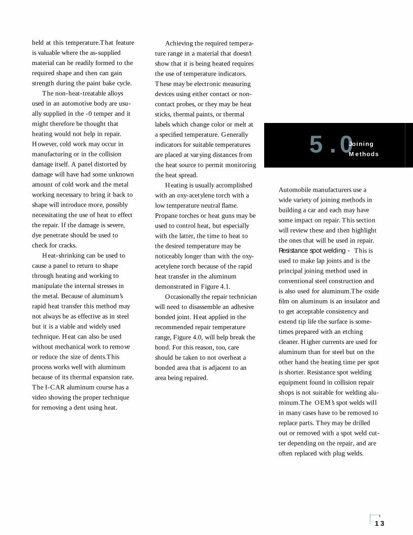
video shows by means of specialimaging the diffe rence in the rate ofheat tra n s fe r. For example: the ph o t o sin Fi g u re 4.1 show the diffe rence int e m p e ra t u re distri b u t i on in com p a ra-ble steel and aluminum panels. Du eto the high con d u c t i v i ty of the alu-minum a larger area is heated, as ca nbe seen in Fi g u re 4.1. With the sameheat source the aluminum takesl onger to re a ch the same tempera t u reas the steel.
The next two temperatures inFigure 4.0 are the annealing temper-atures for heat-treatable and non-heat-treatable alloys. Aluminum isannealed by heating to this rangeand then cooling to room tempera-ture. When annealed, aluminum is inits softest condition. Under theseconditions it has its lowest mechani-cal strength properties and greatestductility, which makes it very work-able. It is rare, however, that it willbe useful to anneal aluminum alloysin the repair process because in mostcases it is desirable to retain as muchas possible of the original propertiesof the alloy being used. It is thatconsideration that sets the range atwhich the work is done from 400˚F(200˚C) to 570˚F (300˚C). When thematerial is heated to within thatrange for the relatively short timesused in repair, it will soften enoughto make it more workable but testsshow that when it has cooled toroom temperature most or all of theoriginal properties are retained.Thelowest temperature in the graphic is350˚F (177˚C) and is the typicaltemperature at which paint is cured.Some of the aluminum alloys in usefor body panels (and some steels aswell) gain in mechanical properties if
t i ve, an unwanted hole may suddenlyappear in the work .O f fsetting thisch a ra c t e ristic is the fact that alu-minum conducts heat mu ch morera p i dly than does steel and in mostcases it will take longer to heat analuminum panel. Tests conducted byThe Aluminum Association for I-CAR for incl u s i on in their cl a s s ro om
4.1 TEMPERATURE DISTR IBUTION IN STEEL AND ALUMINU M
PA N E L S
First imageSteel PanelMaximum temperature: 476˚FTime to reach maximum temperature: 6 sec.
Second image.Aluminum PanelMaximum temperature: 293˚FTime to reach maximum temperature: 6 sec.
Third image.Aluminum PanelMaximum temperature: 477.6˚ FTime to reach maximum temperature: 23 sec.
held at this temperature.That featureis valuable where the as-suppliedmaterial can be readily formed to therequired shape and then can gainstrength during the paint bake cycle.
The non-heat-treatable alloysused in an automotive body are usu-ally supplied in the -0 temper and itmight therefore be thought thatheating would not help in repair.However, cold work may occur inmanufacturing or in the collisiondamage itself. A panel distorted bydamage will have had some unknownamount of cold work and the metalworking necessary to bring it back toshape will introduce more, possiblynecessitating the use of heat to effectthe repair. If the damage is severe,dye penetrate should be used tocheck for cracks.
Heat-shrinking can be used tocause a panel to return to shapethrough heating and working tomanipulate the internal stresses inthe metal. Because of aluminum’srapid heat transfer this method maynot always be as effective as in steelbut it is a viable and widely usedtechnique. Heat can also be usedwithout mechanical work to removeor reduce the size of dents.Thisprocess works well with aluminumbecause of its thermal expansion rate.The I-CAR aluminum course has avideo showing the proper techniquefor removing a dent using heat.
13
Achieving the required tempera-ture range in a material that doesn’tshow that it is being heated requiresthe use of temperature indicators.These may be electronic measuringdevices using either contact or non-contact probes, or they may be heatsticks, thermal paints, or thermallabels which change color or melt ata specified temperature. Generallyindicators for suitable temperaturesare placed at varying distances fromthe heat source to permit monitoringthe heat spread.
Heating is usually accomplishedwith an oxy-acetylene torch with alow temperature neutral flame.Propane torches or heat guns may beused to control heat, but especiallywith the latter, the time to heat tothe desired temperature may benoticeably longer than with the oxy-acetylene torch because of the rapidheat transfer in the aluminumdemonstrated in Figure 4.1.
Occasionally the repair technicianwill need to disassemble an adhesivebonded joint. Heat applied in therecommended repair temperaturerange, Figure 4.0, will help break thebond. For this reason, too, careshould be taken to not overheat abonded area that is adjacent to anarea being repaired.
Automobile manufacturers use awide variety of joining methods inbuilding a car and each may havesome impact on repair. This sectionwill review these and then highlightthe ones that will be used in repair.Resistance spot welding - This isused to make lap joints and is theprincipal joining method used inconventional steel construction andis also used for aluminum.The oxidefilm on aluminum is an insulator andto get acceptable consistency andextend tip life the surface is some-times prepared with an etchingcleaner. Higher currents are used foraluminum than for steel but on theother hand the heating time per spotis shorter. Resistance spot weldingequipment found in collision repairshops is not suitable for welding alu-minum.The OEM’s spot welds willin many cases have to be removed toreplace parts. They may be drilledout or removed with a spot weld cut-ter depending on the repair, and areoften replaced with plug welds.
5.0Joining
Methods

F IGURE 5 .0 R IVET ING
14
Ultrasonic Welding - Not widelyused yet but growing, this techniqueis similar to resistance spot weldingbut uses high energy vibration to jointhe parts. Its advantage is that thereis no heat affected weld nugget as inresistance welding and larger weldareas lead to better shear strength.This type of equipment is also notusually found in collision repairshops.Inert Gas Welding - This is themost common welding method usedfor aluminum.The two types usedare metal arc (called MIG orGMAW) in which aluminum fillerwire is used as the electrode, and gastungsten arc (called TIG or GTAW)in which a tungsten electrode is usedand filler wire may or may not beused. Fluxes and coated rods are notused for aluminum. Inert gas weldingcan be used for butt welds, filletwelds, and also for lap welds bymeans of spot or plug welds. In therepair of light sheet, TIG has nor-mally been employed but, with suit-able equipment, MIG can be satis-factorily used and is the preferredequipment in the collision repairindustry.Oxygas Welding - An old standby,this welding method uses a torch,filler rod and flux to make the weld.It is difficult to do, tends to cause alarge heat-affected zone, and requirescareful flux removal to avoid corro-sion. It is not used by the OEM’sand is found only in specialty appli-cations for repair.
Adhesive Bonding - Chemicalbonding is increasingly in use to joina variety of materials.There are awide range of adhesives available andthey are used in both OEM andrepair scenarios. In repair heat isused to soften adhesive joints so theycan be separated as needed.Weldbonding - Weldbonding is avariant of adhesive bonding devel-oped for automotive use whereinresistance spot welding is employedto assist accurate assembly, to holdthe joint together during cure and toimprove the joint ’s resistance to peel-ing. The spot welding is done
through the uncured adhesive filmwhich is squeezed out by the clamp-ing pressure at the spot locations.For removal heat and spot weld cut-ters may be used.Hemming - This assembly method isused for parts like doors, deck lidsand hoods. Joints are made by fold-ing an edge of one part over on itselfclamping the mating piece in thefold. For aluminum rope hems areusually used.Riveting - A joining method thatdoes not require heat and can beused to join dissimilar materials.Thepresence of a protruding head or
Squeeze-Driven
Breakaway-Stem Rivet
Full Rivet
1.5 TimesDiameter
.5 TimesDiameter
1.5 TimesDiameter
Self-Piercing Rivet
Courtesy of I-CAR
shank limits use to where cosmeticappearance is not a factor unlesscountersunk rivets are used butnonetheless riveting is used widely inrepair. Removal of rivets requiresgrinding and/or drilling. Self-pierc-ing rivets, also called punch rivets, donot require a hole but do require ananvil and therefore access to bothsides of the joint.Screws and Bolts - Also not requir-ing heat, these fasteners offer theadvantage of being removable. Theyare frequently used in vehicle con-struction and in repair.Clinching - Clinching is used to jointhin materials and is a combinationcompression and punching operationresulting in joints similar to spotwelding or riveting. The sheet itselfis its own fastener and there is nohole in the sheet. In repair clinchedjoints are separated by drilling orusing a spot weld cutter.
Repair Joining Methods:
Mechanical FasteningThe repair shop can make use ofmechanical fastening in many appli-cations, including those where a spotweld was the original joint. Standardriveting operations are used for alu-minum. Typically rivets are of severaltypes. A conventional rivet will havea solid or tubular shank. It requires ahole and access to both sides of thejoint so that it can be struck on oneend against a backing anvil on theother. Squeeze-driven breakawaystem rivets, perhaps most common in
15
repair and often called pop or blindrivets, require a hole and are usedwhere only one side access is avail-able.The collision repair technicianmust give attention to materials.Most common rivets are steel.Section 2 discussed corrosion andpointed out that unprotected alu-minum and steel in contact willresult in corrosion of the aluminumunder automobile service conditionsof moisture, salt and dirt.Thereforeonly stainless steel and aluminumfasteners are recommended and areavailable for most applications.Squeeze-driven breakaway-stem riv-
ets may have an aluminum body andan aluminum stem but the mostcommon ones will usually have asteel stem. In some kinds the stempulls through but in most the stemstays in. This could represent a cor-rosion hazard if moisture can get inand aluminum or stainless stems arepreferred. It is not possible to speci-fy rivets for each application in thismanual and the repair shop willhave to rely on the auto manufactur-er’s recommendations for eachrepair.
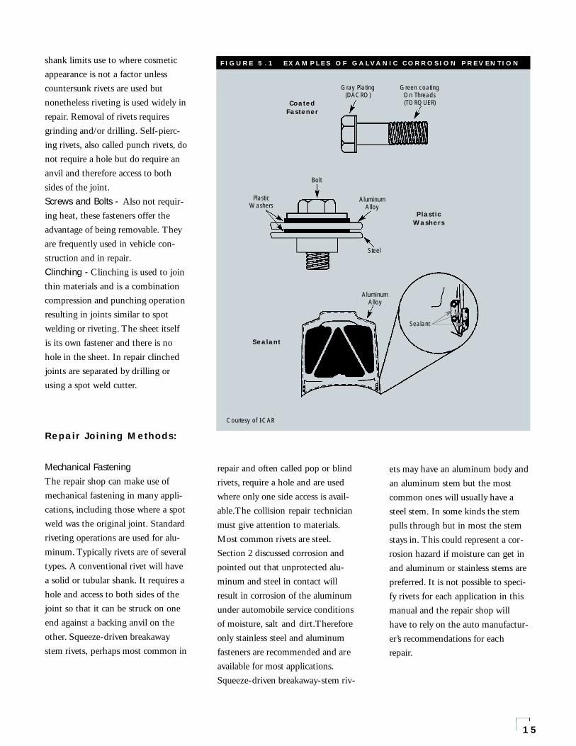
F IGURE 5 .1 EXAMPLES OF GALVANIC CORROSION PREVENTION
CoatedFastener
Gray Plating Green coating(DACRO) On Threads
(TORQUER)
PlasticWashers
PlasticWashers
Bolt
Aluminum Alloy
Steel
Sealant
Sealant
AluminumAlloy
Courtesy of I-CAR
requires the proper technique andequipment to give best quality. TIGremains a viable way of repairing alu-minum and full treatment of theTIG and MIG processes are given inThe Aluminum Association publica-tion Repair ofAluminum AutomotiveSheet by Welding AT1.
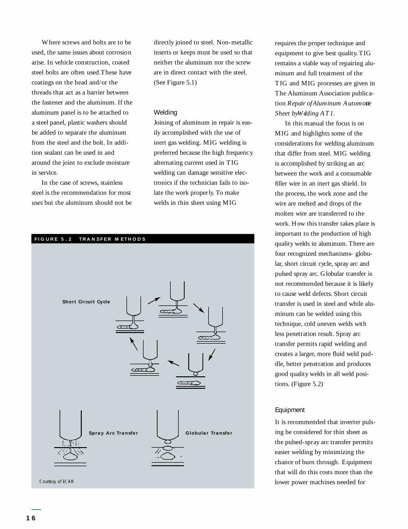
In this manual the focus is onMIG and highlights some of thec on s i d e ra t i ons for welding aluminumthat differ from steel. MIG weldingis accomplished by striking an arcb e tween the work and a con s u m a b l efiller wire in an inert gas shield. I nthe pro c e s s , the work zone and thew i re are melted and drops of themolten wire are tra n s fe r red to thew o rk . H ow this tra n s fer takes place isi m p o rtant to the pro d u c t i on of highq u a l i ty welds in aluminum. T h e re arefour re c o g n i zed mechanisms- globu-l a r, s h o rt circuit cycl e, s p ray arc andpulsed spray arc . Globular tra n s fer isnot re c ommended because it is likelyto cause weld defe c t s . Sh o rt circ u i tt ra n s fer is used in steel and while alu-minum can be welded using thist e ch n i q u e, cold uneven welds withless penetra t i on re s u l t . Sp ray arct ra n s fer permits rapid welding andc reates a larger, m o re fluid weld pud-dl e, better penetra t i on and pro d u c e sgood quality welds in all weld posi-t i on s . ( Fi g u re 5.2)
Equipment
It is recommended that inverter puls-ing be considered for thin sheet asthe pulsed-spray arc transfer permitseasier welding by minimizing thechance of burn through. Equipmentthat will do this costs more than thelower power machines needed for
16
Where screws and bolts are to beused, the same issues about corrosionarise. In vehicle construction, coatedsteel bolts are often used.These havecoatings on the head and/or thethreads that act as a barrier betweenthe fastener and the aluminum. If thealuminum panel is to be attached toa steel panel, plastic washers shouldbe added to separate the aluminumfrom the steel and the bolt. In addi-tion sealant can be used in andaround the joint to exclude moisturein service.
In the case of screws, stainlesssteel is the recommendation for mostuses but the aluminum should not be
directly joined to steel. Non-metallicinserts or keeps must be used so thatneither the aluminum nor the screware in direct contact with the steel.(See Figure 5.1)
WeldingJoining of aluminum in repair is eas-ily accomplished with the use ofinert gas welding. MIG welding ispreferred because the high frequencyalternating current used in TIGwelding can damage sensitive elec-tronics if the technician fails to iso-late the work properly. To makewelds in thin sheet using MIG
FIG URE 5 .2 TRANSFER METHODS
Short Circuit Cycle
Spray Arc Transfer Globular Transfer
Courtesy of I-CAR
short circuit transfer. 220-240 voltpower supplies work best.The 110-120 volt power supplies found inmany shops are generally unaccept-able for quality aluminum welding.This is a particular burden on theindividual that must supply his ownequipment, a situation often foundnowadays.The welding industry rec-ognizes the situation and types ofequipment balancing low cost withadequate power for spray transfer onaluminum are being developed.
In addition to the DC powersource, the repair technician needs aninert gas supply of 100% argon withthe proper regulator, flow meter andthe necessary hose and fittings; awelding gun and wire feeder, helmetwith no less than #10 shade, protec-tive clothing, and a stainless steelwire brush.
There are several differentdesigns of wire feeder on the market.The major differences among theminvolve the location of the motor anddrive rolls which feed the wire. Onetype, called a “push” feeder places themotor and feed rolls back at thefeeder and pushes the wire through aconduit into and through the weld-ing gun.This type of feeder will per-form acceptably on larger diameterand/or higher strength aluminumwires (1/16 in. (1.5 mm) and largerand with 5356 instead of 4043) butprobably will not reliably feed thesmaller diameter wires.
17
Another type, called a “pull”feeder, places the motor and feedrolls in the welding gun and pulls thewire through a conduit into andthrough the gun.The pull feederthough has the same limitations asthe push feeder with respect to alu-minum filler alloys.
A third type, the “push-pull”feeder, uses two motors and two setsof drive rolls, one in the feeder andone in the gun, to obtain the mostuniform feeding for the small diame-ter (3/64 (1.2 mm) and lower) weld-ing wire used for sheet metal.
The last type, the “1-lb. spoolgun”, holds a 1-lb. spool of wire righton the welding gun. Since the wire isfed only a short distance a singlemotor and drive roll is adequate tofeed any wire diameter of 1/16 in. orlower. The guns tend to be light dutyand so should not be used for heavysection welding but are per fectly ade-quate for welding sheet gauges.These guns also tend to be the leastexpensive.The added bulk caused byhaving the wire spool hung on thegun can sometimes be a problemwhen welding under conditions ofrestricted access.
Whatever feeder is used, nylon orTeflon gun liners are recommended,since the coiled steel wire liner usedwhen welding steel will shave thesoft aluminum wire and clog the gunwith fine shavings. For the same rea-son, any inlet and outlet guides usedin the feeder gun should be plastic,not metallic. Drive rolls should bedesigned for soft wires. Never useknurled drive rolls. Drive rolls of theU- or V- groove, top and bottom, arepreferred for aluminum.
Wire feeders should possess a“touch-start” or “slow run-in” arc ini-tiation feature.This is necessary foruse with the constant energy (con-stant current) type of power supply.This feature is also preferred withconstant voltage power supplies tominimize arcing in the contact tubeand/or frequent “burn-backs” to thecontact tube.The “touch-start” fea-ture, which delays electrode feedinguntil the electrode is touched to thebase metal, provides: (1) better weldfusion at the starting location thancan be obtained with a fast run-infeed, (2) rapid restriking of the arcfor termination crater filling, and (3)increased productivity resulting fromless “burn-backs” due to high currentsurges at starts.
An additional feature desired inthe MIG welding gun is a long con-tact tube, 4-6 in (100-150 mm), toprovide multiple points of currentcommutation between the electrodeand the contact tube. A long contacttube in combination with the“touch-start” wire feed feature canprovide many arc starts without a“burn-back”.
Filler Wire
Filler wire is selected from Table 5.3.Typical wire diameters are .030 in.(0.8 mm), .035 in. (0.9 mm), and3/64 in. (1.12 mm).The filler wireitself must be free of grease, dirt, orforeign matter, otherwise unsoundwelds may result. Electrode wire issupplied on spools, with the spool

s i ze depending on the type of gun andfe e d e r. The coll i s i on repair tech n i c i a nshould make certain that spools offiller wire are kept packaged and dryuntil ready to use. Unused wire shouldbe re t u rned to its original ca rt on orput in a sealed plastic bag.
TechniqueThe welding gun should be held atan angle of 5˚ to 20˚ perpendicular tothe work, pointed in the direction oftravel. After the arc is initiated, thegun is moved forward at the properspeed.The angle of the gun is
18
dependent upon both speed of traveland the position of the joint. Thisangle should be adjusted to give theproper cleaning action, depth of pen-etration, and bead contour.
When welding unequal sections,direct the arc against the thickerpiece to obtain equal fusion in thetwo edges. A slight weave may behelpful when welding thin gaugematerial to thicker gauge; the arc isalways directed to the thicker mem-ber and the weld pool is washed upto the thinner member. Regardless ofthe technique used, it is important towatch the edge of the weld pool and
the arc to see that the edge of thepool fuses into the adjacent metal.
Weld craters must be filled inwhen welding aluminum. Severalmethods can be employed to avoidor reduce the crater at the end of theweld pass.The first option is toincrease the weld speed just beforebreaking the arc. This is best accom-plished on the surface of a previousweld deposit or along the side of abevel, rather than in an unfused rootof a weld. A second option is toreverse direction and accelerate weldbackwards to tail out the weld. Athird option is to break and restrikethe arc to build up the crater areabefore it solidifies.This is done bestwith a “touch-start” wire feed fea-ture. A slow or fast run-in feature istoo slow in reinitiating the arc tocrater fill effectively before solidifica-tion and possible cracking of theweld crater.
Another, better, method is to use“run-off ” tabs. It is recommendedthat “run-off ” and “run-on” tabs beused whenever feasible. These can besmall scraps of aluminum placed ateach end of the weld joint on whichthe weld is started or stopped asshown in Figure 5.4.
Backings are very important toachieve weld quality in thin sheetwith MIG welding. Close sheet fit-up over the backup bar will be diffi-cult to achieve in areas of sheet tears;however, effort should be made tobring the sheet edges together.Grooved removable backing is com-monly used. Openings in excess of.015 to .020 in. (0.4-0.6 mm) in thinsheet are difficult to bridge without
TABLE 5 .3 F I LL ER WIRE SE LE CT ION CHART
For welding these alloy series 2xxx 5xxx 6xxxto these alloy series (1)
2xxx 4043 Not 41454145 recommended 4047
40435xxx Not 5356 5356
recommended 5183 51836xxx 4043 5356 4043
4047 5183 5356(2)
4145
(1) The preferred filler alloy is shown first.(2) 6009, 6010, 6013 and 6111 alloys have high copper content and should be welded to another
6xxx series with 5356 electrode wire
F IGURE 5 .4 WELD TA B
Weld Tab

19
TABLE 5 .5 TYP ICAL PRACT IC ES F OR GAS METAL ARC (MIG) WELDING
Material DC Electrode Argon Number Thickness Weld Position Joint Design Current Arc Diameter Gas Flow of
(in.) (A) (V) (in.) (cfh) Passes
0.040 All Square Butt 40-45 16-20 0.030 30 1Fillet and Lap 50-60 16-20 0.030 30 1
1/16 All Square Butt 60-80 16-20 0.030 30 1Fillet and Lap 60-90 17-21 0.030 30 1
3/32 Flat Square Butt 70-110 18-22 0.030 30 1Horiz., Vert., Square Butt 110-120 18-22 0.030-3/64 30 1and OverheadAll Fillet and Lap 100-130 18-22 0.030 30 1
1/8 Flat Square Butt 110-130 19-23 3/64 30 1Horiz. and Vert. Square Butt 110-120 19-23 3/64 30 1Overhead Square Butt 110-120 19-23 3/64 40 1Flat Fillet and Lap 125-150 20-24 0.030-3/64 30 1Horiz. and Vert. Fillet and Lap 110-130 19-23 0.030 30 1Overhead Fillet and Lap 115-140 20-24 0.030-3/64 40 1
3/16 Flat Square Butt 175-200 22-26 3/64 40 1Horiz. and Vert. Square Butt 150-200 23-26 3/64 35 1Overhead 60’ Single Vee 150-175 23-27 3/64 60 1Flat Fillet and Lap 180-210 22-26 3/64 30 1Horiz. and Vert. Fillet and Lap 130-175 21-25 0.030-3/64 35 1Overhead Fillet and Lap 130-190 22-26 0.030-3/64 45 1
TABLE 5.6 TYP ICAL PRACT IC ES FOR GAS METAL ARC (MIG) WELDING
Material DC Electrode Argon Number Thickness Weld Position Joint Design Current Arc Diameter Gas Flow of
(mm) (A) (V) (mm) (L/min) Posses
0.8 All Square Butt 40-45 16-20 0.6 14 1Fillet and Lap 50-60 16-20 0.6 14
1.6 All Square Butt 60-80 16-20 0.6 14 1Fillet and Lop 60-90 17-21 0.030 0.6 14
2.4 Flat Square Butt 70-110 18-22 0.6 14 1Horiz., Vert., Square Butt 110-120 18-22 0.6-1.2 14 1and OverheadAll Fillet an Lop 100-130 18-22 0.6 14 1
3.2 Flat Square Butt 110-130 19-23 1.2 14 1Horiz. and Vert. Square Butt 110-120 19-23 1.2 14 1Overhead Square Butt 110-120 19-23 1.2 19 1Flat Fillet and Lop 125-150 20-24 0.6-1.2 14 1Horiz. and Vert. Fillet and Lap 110-130 19-23 0.6 14 1Overhead Fillet and Lap 115-140 20-24 0.6-1.2 19 1
4.8 Flat Square Butt 175-200 22-26 1.2 19 1Hertz. and Verl. Square Butt 150-200 23-26 1.2 16 1Overhead 60’ Single Vee 150-175 23-27 1.2 28 1Flat Fillet and Lop 180-210 22-26 1.2 14 1Horiz. and Vert. Fillet and Lop 130-175 21-25 0.6-1.2 16 1Overhead Fillet and Lop 130-190 22-26 0.6-1.2 21 1

20
melting the sheet edges back. Ifexcessive gap occurs, an integral alu-minum backing strap can be usedadvantageously.
See Table 5.5 and 5.6 for weldingprocedures and practices for MIGwelding aluminum sheet.
Plug WeldingWhen welding two thickness’ ofsheet together in a lap configuration(as opposed to a butt weld), the plugweld is a good technique to use. Inplug welding, shown in Figure 5.7, ahole is drilled or punched in the topsheet.The weld is then made in thehole and joins the top and bottomsheets together.
A few cautions are in order. Thehole should be 3/8-1/2 in. (9-12mm)diameter. Larger diameter holesincrease the risk of burning throughthe backing sheet and will create alarger pool leading to more shrinkagewhile smaller holes usual ly result inmarginal quality welds, i.e., poorfusion.The temptation is to place thewelding gun in the center of the hole,strike the arc, and let the weld spreadout to melt the edges of the hole.
This practice is not recommendedand often results in poor fusionbetween the top and bottom sheet.The recommended practice is toposition the gun at a convenient spoton the circumference of the hole,strike the arc, delay briefly beforebeginning to move to allow the weldpuddle to be established, and travelsmoothly around the circumferenceof the hole, as shown in Figure 5.7.During welding the gun should beheld roughly perpendicular to thehole but with a small leading angle.
Another technique sometimesused to weld two thickness’ of sheettogether in a lap joint is MIG spotwelding. This technique is similar toplug welding except no hole is pre-sent in the top sheet. MIG spotwelds, however, have been shown toexhibit a lack of consistency fromweld to weld and the mechanicalproperties are not as good as a plugweld. Plug welds are therefore rec-ommended for most applications.
For additional discussion ofwelding, refer to AluminumAssociation publication AT1 and theI-CAR aluminum repair coursematerials. Welding of aluminum isdifferent from welding steel andsome of the key differences may besummarized as follows (DC constantenergy power supply is assumed):• Spray-arc transfer is used for alu-
minum and this necessitates morepowerful welding equipment withpulsing power supplies.
• Pure argon is used for the shield-ing gas. CO2 is never used.
• The welding gun is angled to thedirection of travel and pushed.Pulling, or dragging, should notbe employed.
• When welding vertically, alu-minum is welded from the bottomup, just the opposite of steel.
• Push-pull feeders or spool gunsare recommended for aluminum.
• Spiral steel liners are not used tofeed aluminum wire, nor areknurled drive rolls.
AdhesivesAdhesives are widely used to makelap and flanged joints in vehicle con-struction for a number of reasons.Bonded joints have better stiffnessand fatigue strength than spot weld-ed or mechanically fastened joints.They can be used to join differentkinds of materials and differentthickness’ of materials. Adhesives alsocan act as electrical and thermal insu-lation and form a barrier to corro-sion, although some organic adhe-sives are adversely affected if exposedto moisture leading to reducedstrength over time. Adhesives areparticularly well suited to joining alu-minum because the inherent corro-sion resistance of aluminum and thestability of a pretreated aluminumsurface make bonded joints strongand durable even in adverse environ-ments. Appearance is good becausethere are no protruding fastenerheads or weld beads and nuggets. Forautomotive aluminum they can beused alone or in conjunction withspot welding or riveting.Weldbonding is a technique devel-oped for automotive productionwhere resistance spot welding is usedto position and to support the jointduring cure, and to improve the peelstrength of the joint.
F IGURE 5.7 P LUG WELDING
Proper wireplacement for plug welding
There are many kinds of adhe-sives used by the OEM’s. Some areone-part and heat-cured, some aretwo-part using a room temperature,induction and/or an elevated temper-ature cure, some are anaerobic (cur-ing in the absence of air) and somecure by exposure to ultraviolet light.They are based on various types oforganic polymers such as vinyl, ure-thane, acrylate, epoxy, phenolic, orpolyamide which are modified withfillers and additives to provide a verywide range of properties.
A different balance of productproperties such as strength, tough-ness, flexibility, creep resistance,vibrations damping, impact strengthand failure mode will be required for each application. Various processingproperties may be even more impor-tant, for instance, tolerance to lubri-cants, pumpability, slump resistance,curing characteristics or expandabili-ty. OEM’s may require the use of aproduction adhesive or specify par-ticular repair products. In either case,the technician must follow theOEM’s recommendations.
Increasingly, adhesives are beingsupplied in easy-to-use forms andpackaging.
Adhesive resins can be appliedquickly and without mess. Two-partpaste adhesives are supplied in dualsyringe cartridges which automatical-ly dispense the correct ratio of resinand hardener. These dual cartridgescan be used in a manual or pneumat-ic gun and are fitted with disposablemixer tubes. Mixer tubes are avail-able in a wide range of sizes (diame-ter, length, and number of vanes). Toobtain correct mixing it is important
21
to use the recommended tube size.Always discard the first few inches ofadhesive dispensed from a mixer tubeto insure adequate mixing.
Adhesive resins are generallyharmless to handle provided thatnormal precautions for handlingchemicals are observed.The uncuredmaterials must not be allowed tocome in contact with foods or foodutensils, and for many products it isadvisable to prevent the uncuredmaterials from coming in contactwith skin, since people with particu-larly sensitive skins may be affected.The wearing of impervious rubber orplastic gloves will normally be recom-mended; likewise the use of eye pro-tection and adequate ventilation inthe working area is recommended.The skin should be washed at theend of each working period with soapand warm water. Do not use solventswhich can carry chemicals into theskin. Disposable paper - not cloth -towels should be used to dry skin.
This publication repeatedlypoints out the necessity of propersurface preparation, whether forwelding, refinishing, or, in this, sec-tion, adhesive bonding. The strengthand durability of the joint dependson adequate preparation. SomeOEM’s may state that replacementpanels need not have further prepara-tion on the replacement part if it issupplied coated as they have confi-dence in the adhesion of the coating.In any case the old, or separated, partwill have to be cleaned.The oldadhesive can be removed by grindingor sanding to a clean aluminum fin-ish. From there the choice of surfacepreparation is dictated by the recom-
mended adhesive system and anypretreatment or primers will bedesigned so that full strength of thebond is obtained.The collision repairshop may have primers on hand forrefinishing but these may or may notbe suited to a given adhesive andshould not be used without the adhe-sive manufacturers recommendation.Again, the OEM’s will have specificrecommendations for the surfacecleaning and pretreatment for eachadhesive they specify for repair use.
The key to the successful refinishingof aluminum is in the preparation ofthe surface. Whether the purpose ofthe coating is to smooth the work, toprovide protection, or to give adesired appearance, that coating muststay in place and intact. Dirt, grease,and such contaminants must be com-pletely removed. On a new clean alu-minum surface, the oxide film issmooth and hard and needs to betreated to give a satisfactor y “tooth”for many coatings. (Oddly enough, aweathered aluminum surface withsubstantial oxide buildup will, ifclean, take a coating more readily butthis is not the situation the techni-cian will have.) Systems offered bythe coating manufacturers recognize
6.0Refinishing

aluminum’s surface characteristics intheir recommendations.
When panels have beenreworked it is often necessary to usebody fillers to smooth minor imper-fections before final painting. Mostof these fillers are polyester based.Some are formulated to be applieddirectly to clean aluminum whileothers require a primer, usuallyepoxy. Procedures are describedbelow.
The final step in the repairprocess is to restore the vehicle to itsoriginal appearance. All the majorOEM paint suppliers, plus numer-ous other coatings manufacturers,offer aftermarket paint repair sys-tems for use in collision repair shops.Care should be taken to make cer-tain the products are recommendedspecifically for aluminum as opposedto general metal, i.e., steel or galva-nized, refinishing. Most of the pro-cedures for these repair systems arequite standard for all the suppliers.However, there are some distinctdifferences and care must be takento follow the supplier’s recommenda-tions, particularly if warranty claimsare to be upheld.
The first situation to considerfrom a refinishing point of view iswhen the work is sanded to baremetal. Clearly when this happensnot only is the OEM metal pretreat-ment removed but there is also thepossibility of contamination of thebare metal surface. What follows is ageneric description of a paint repairprocedure when sanding to baremetal is required.
22
Step 5 - This material is ordinarily achromium based pretreatment prod-uct.Step 8 - Some companies recom-mend an epoxy etch primer whileothers suggest a non-etch primer.An etch primer is often recom-mended by a supplier especially ifStep 5 is omitted.
When it is not necessary to sanddown to bare metal, i.e., in areas oflight damage, then the followingprocedure can be used:
Procedure B
Steps1 Clean around areas to be
repaired.2 Dry sand using fine grit (mini-
mum 220-240) sandpaper.3 Clean to remove all debris.4 Apply filler/ surfacer.5 Air dry.6 Apply appropriate topcoats.
Earlier it was noted that it isoften necessary to use body fillers tosmooth repaired surfaces. Ideallythey should be applied to sandedand pretreated aluminum as outlinedin Steps 1-7 of Procedure A above.When approved by the supplier, it isalso acceptable to apply fi ller to acleaned metal surface without usingthe aluminum conditioning treat-ment. (Omit Steps 5 and 6 inProcedure A).
Procedure A
Steps1 Clean around area to be
repaired.2 Dry sand to bare metal using
180-220 grit paper.3 Carefully clean to remove all
residual debris on bare metal.4 Water rinse.5 Apply aluminum conditioning
treatment.6 Water rinse.7 Air dry.8 Apply epoxy primer.9 Air dry.10 Apply primer/surfacer.11 Air dry.12 Apply appropriate topcoats.
Notes
Step 1 - The purpose of this firststep is to remove dirt, grease, andwaxes which otherwise could beground into the metal surface duringsanding. The coatings suppliers havea number of recommended productsfor this step. This cleaner is generallynot the same as the cleaner describedin Step 3.Step 2 - The sanding should produceadequate surface roughness to allowgood mechanical interlocking withthe primer while being sufficientlysmooth to achieve satisfactory paintappearance.Step 3 - This is arguably the mostcritical step in the repair process. Thecoatings suppliers typically specify anacidic cleaner for this step but insome cases solvent wiping alone isused. In any case careful removal ofall contaminants is essential to goodpaint adhesion.

Absorption - the ability of a particu-lar alloy composition to use or absorbanother alloy or scrap as part of themakeup of a new aluminum ingot.
Aging - a thermal treatment used tomodify and/or stabilize mechanicalproperties.
Alloy - a metallurgical mixture ofaluminum with selected other ele-ments to give a desired set of perfor-mance characteristics.
Alumina - aluminum oxide, therefined raw material from which newprimary aluminum is produced.
Annealing - using heat to remove theeffects of heat-treatment or strainhardening.
23
7.0Glossary
of Terms
Bauxite - the ore from which alumi-na is refined.
Cast products - parts produced bypouring molten aluminum alloys intoa mold.
Contaminant - any material in scrapthat is not wanted or needed in recy-cling.
Delacquering - the term used in thealuminum industry to describe coat-ing removal in recycling.
Filler alloy - additional aluminumalloy in the form of rod or wire usedin inert gas welding to augment thebase metal melted to produce theweld.
Heat-treatable alloy - an alloy thatgains its mechanical properties frombeing heated to elevated temperatureand rapidly cooled, usually followedby other low temperature thermaltreatment.
Ingot - stock for making products ofaluminum products. Unalloyed ingotis often referred to as “pig”.
Non-heat-treatable alloy - an alloythat gains its properties by physicaldeformation, or strain hardening,obtained from mechanical working.
Permanent joint - used in this man-ual to describe a joint not normallyseparated by the auto dismantler dur-ing the recycling process.
Primary aluminum - new aluminumfrom ore produced by the Hall/Heroult process. Also called virginaluminum.
Secondary aluminum - aluminumalloys produced by the remelting andreprocessing of scrap.
Segregation - achieving high qualityscrap by keeping different materialstreams apart.
Sorting - achieving high qualityscrap by mechanically or thermallyseparating mixed materials.
Sustainable recyclability - the abili-ty of aluminum alloys to be recycledover and over.
Thermal treatment - the use of heat to achieve desired properties inaluminum alloys other than by heat-treating.
Temper - the final set of propertiespossessed by a given alloy after pro-cessing.
Wrought products - those productsin which some physical deformationis used to give the final productform, including sheet and plate,extrusions, forgings, rod, bar andwire. Any product that is not cast.

24

25


![EUROPEAN COMMISSIONdesignated in accordance with document 60008 of 22.2.2001 ‘Mise en place de la Charte des ordonnateurs’. Grant Agreement number: [insert number] [insert acronym]](https://static.fdocuments.us/doc/165x107/5f04c8057e708231d40fac98/european-commission-designated-in-accordance-with-document-60008-of-2222001-amise.jpg)


