![B en AntiSurgeControlValve[1]](https://static.fdocuments.us/doc/165x107/577d364b1a28ab3a6b92bd43/b-en-antisurgecontrolvalve1.jpg)
T500W en B
100
www.technifor.com Technifor reserves all rights to modify its products. This document is non contractual. USER MANUAL T500W Marking program in Windows® for communication with machines integrating the T05 program Ref. DCD01/3077 - T500W_en_B - Last updated: 07/2010
Transcript of T500W en B

USER MANUAL
T500WMarking program in Windows® for communication with machines
integrating the T05 program
Ref
. DC
D01
/307
7 -
T50
0W_e
n_B
- L
ast
upd
ated
: 07
/201
0
www.technifor.comTechnifor reserves all rights to modify its products. This document is non contractual.

Table of contents
A - Introduction .................................................................................................................... 41. Unpacking .............................................................................................................................................. 42. General characteristics of the program .................................................................................................. 43. Minimum configuration of the PC ........................................................................................................... 44. Installation .............................................................................................................................................. 55. Program functions .................................................................................................................................. 6
Customization ................................................................................................................................... 6 Type of blocks ................................................................................................................................... 6 Managing the 8 Input / 4 Output board ............................................................................................. 7 Functions within the blocks ............................................................................................................... 7 Character styles ................................................................................................................................ 7 Marking management ....................................................................................................................... 7 Adjustable settings ............................................................................................................................ 7 Various functions ............................................................................................................................... 7
6. Starting-up the program ......................................................................................................................... 8 Set-up of the protection key .............................................................................................................. 8 RS232 connection for communication with PC ................................................................................. 8 Serial management: configuring ....................................................................................................... 9 Starting-up the program .................................................................................................................... 9
7. The different program menus ............................................................................................................... 10 Main menu ...................................................................................................................................... 10
8. Functions of the keys used ................................................................................................................... 11 Creating a marking file .................................................................................................................... 11 Marking preview .............................................................................................................................. 11
9. Use of graphic elements ....................................................................................................................... 1210. Definition of a marking file .................................................................................................................. 12
B - "Machines" menu ......................................................................................................... 131. CCU configuration ................................................................................................................................ 132. Virtual CCU’s ........................................................................................................................................ 143. Test the connection .............................................................................................................................. 14
C - Machine parameters .................................................................................................... 151. About .................................................................................................................................................... 152. Configuring variables (machine variable(s)) ......................................................................................... 15
Programming within a marking file .................................................................................................. 16 Compiling a series of variables ....................................................................................................... 16
3. Configuring counters (machine counter(s)) .......................................................................................... 17 Incrementation by batch / incrementation of a counter based on the status of an Input ................. 18 Setting of the counter’s reset .......................................................................................................... 18
4. Configuring shifts .................................................................................................................................. 215. Setting Date/Time ................................................................................................................................. 226. Configuring Day/Month/Year format ..................................................................................................... 22
Year variable (YS) ........................................................................................................................... 23 Month variable (MS) ........................................................................................................................ 23 Day of the week variable (DS) ........................................................................................................ 24 Day in the month variable (JS) ........................................................................................................ 24 Hour variable (HS) .......................................................................................................................... 25
7. CCU memory ........................................................................................................................................ 26 Saving or loading files ..................................................................................................................... 26 Font management ........................................................................................................................... 27 Logo management .......................................................................................................................... 28
D - "Marking" menu ........................................................................................................... 301. Standard marking ................................................................................................................................. 30
Marking "One time" (F10) ................................................................................................................ 30 Marking "N times" ............................................................................................................................ 30 "Infinite" marking ............................................................................................................................. 30
Ref. DCD01/3077 - T500W_en_B 2/100
2. "Independent" marking ......................................................................................................................... 31 "Infinite" independent marking ........................................................................................................ 31 Cancel ............................................................................................................................................. 31
3. Simulation ............................................................................................................................................. 31 File simulation (F9) .......................................................................................................................... 31 Simulation of the current block (F4) ................................................................................................ 31
4. Start-up marking ................................................................................................................................... 32
E - "Edit file" menu ............................................................................................................ 331. Block number ....................................................................................................................................... 342. Block name (label) ................................................................................................................................ 343. Type of marking .................................................................................................................................... 34
Linear marking ................................................................................................................................ 35 Radial marking ................................................................................................................................ 36 Marking of simple geometric shapes ............................................................................................... 38 2D code ........................................................................................................................................... 41 Function .......................................................................................................................................... 43 Rotary device (optional) .................................................................................................................. 60
4. Text to be marked ................................................................................................................................ 61 List of key words ............................................................................................................................. 61 Key words ....................................................................................................................................... 62 Splitting a variable ........................................................................................................................... 63
5. Properties of the file ............................................................................................................................. 65 XY head marking speed .................................................................................................................. 65 File variable(s) ................................................................................................................................. 67 Rotary device speed ....................................................................................................................... 67 File counter(s) ................................................................................................................................. 70
6. Example of a file ................................................................................................................................... 717. Conversion of the units into inches ...................................................................................................... 728. Multiple file editing ................................................................................................................................ 72
F - Tools ............................................................................................................................ 731. Conversion of old file formats ............................................................................................................... 732. Logo editor ........................................................................................................................................... 74
Menu bar ......................................................................................................................................... 74 Toolbar ............................................................................................................................................ 75 Editing tools ..................................................................................................................................... 81
3. Block ..................................................................................................................................................... 844. File comments ...................................................................................................................................... 855. Marking preview ................................................................................................................................... 85
Grid ................................................................................................................................................. 85 Zoom in / zoom out ......................................................................................................................... 86 Image .............................................................................................................................................. 86 Block ............................................................................................................................................... 87
G - "Configuration" menu .................................................................................................. 881. Access modes ...................................................................................................................................... 88
"Administrator" mode ...................................................................................................................... 88 "Operator" mode ............................................................................................................................. 90
2. Databases ............................................................................................................................................ 91 Integration of external data in the marking files .............................................................................. 91 Database configuration ................................................................................................................... 92 Creation of a new profile ................................................................................................................. 97
3. Preferences .......................................................................................................................................... 98 Open and save directory ................................................................................................................. 99 Starting mode .................................................................................................................................. 99 Block color ....................................................................................................................................... 99 Display options ................................................................................................................................ 99 Start marking file ............................................................................................................................. 99
H - Appendix ................................................................................................................... 100
Ref. DCD01/3077 - T500W_en_B 3/100

AAIntroduction This manual corresponds to the 1.42 version of the program.
1. Unpacking
2. General characteristics of the program
Standard marking program T500W is installed on a computer equipped with Windows® XP / Vista.
Used to:
• program files for marking:
- set text - variable text: . date (using various set or customized formats) . counter (incrementation, decrementation) - logos - shapes: lines, circles
• screen preview of all data entered in the marking file.
• connect to a data base to collect the text to mark.
• convert the old marking files issued from T101W.
3. Minimum configuration of the PC
Contents of the box:
• 1 marking program and its technical manual on CD-ROM, if ordered
• cable (if ordered)
• USB or parallel port key
Minimum Recommended
Operating system Windows® XP Windows® Vista
Processor Pentium III Pentium IV
RAM 1 Go / GB 2 Go / GB
Screen resolution 1024 x 768 1280 x 1024
Hard disk 50 Mo / MB > 200 Mo / MB
Some screenshots may be different from those displayed in the program (depending on the options selected, the program version, the marking
machine type).
Ref. DCD01/3077 - T500W_en_B 4/100

AIntroduction A
4. InstallationIf an earlier version of the program is already installed, uninstall it manually (control panel).
If, after having inserted the CD, the installation still does not automatically start, launch setup.exe with the CD-ROM. Do not connect the protection key on the computer right away. The screens must follow on from one another:
Ref. DCD01/3077 - T500W_en_B 5/100

AIntroduction A
At the end of T500W installation, install the protection key's driver by launching "Sentinel Protection Installer" from the CD-ROM.5. Program functions
Customization
• multilingual: program language selection
• "Supervisor" mode / "Operator" mode (access rights to certain functions or entry fields for text or coordinates)
• units (mm or inches)
Type of blocks
• linear marking (choice of the angle)
• radial marking
• logos
• 2D code
• pilots a rotating third axis (DMC15/DMC25) for marking on circular parts
• function
Ref. DCD01/3077 - T500W_en_B 6/100

AIntroduction A
Managing the 8 Input / 4 Output board• BRANCH instruction: file selected depending on Input status
• WAIT INPUT instruction: waiting for Entry condition to continue
• SET OUTPUT instruction: specification of the output state
Functions within the blocks
• delay between blocks (DELAY)
• marking of simple geometric shapes:
- circles - lines
Character styles
• marking effects:
- normal - inverted - mirror - reflected
• alignment
• compression / expansion
• inclination
• spacing between characters
Marking management
• standard marking:
- marking 1 part - marking N parts - infinite marking
• independent marking
Adjustable settings
• customized speeds for marking and movement
• force (depth)
• variables:
- 10 numeric, alphanumeric, alphabetic or hexadecimal counters, which can be reset each time there is a change in year, month, day, hour, day of the week, shift, Input
- 10 alphanumeric variables - shift codes (Q) set according to the day of the week (up to 5 shifts per day) - date and time based on CCU system, using the keywords:
. DD - MM - YYYY - YY - Y - hh - mm - ss - WW - CCC
. m (mark first digit of the minutes)
. customized formats DS (day/week), JS (day/month), MS (month) and YS (year)
• choose a character font
Various functions
• data importation from a file
• creation of simple logos
• marking preview
• simulate marking file (no marking on part)
Ref. DCD01/3077 - T500W_en_B 7/100

AIntroduction A
6. Starting-up the programSet-up of the protection key
Place the protection key on the parallel or USB port of the computer. A printer can be connected to this key. In some cases, the printer must be plugged so that the program can detect the key.
Connect the protection key. Launch T500W, either via a shortcut on the Desktop, either via "Start - Programs -
Technifor - T500W".
RS232 connection for communication with PC
Connect the machine to the RS232 output of the computer in order to mark. For other connections, see the machine’s manual.
Rear view of the machine
1 : Accessory connection (start cycle/emergency stop button box or start cycle foot pedal...) 2 : RS232 connection for communication with PC 3 : USB_B DEVICE connection 4 : USB_A HOST connection (USB key)5 : Ethernet connection
Check that the CCU is plugged and that the computer-to-CCU connection cable is connected.
The T500W program is compatible only with Technifor machines.
1
2
3
4
5
Ref. DCD01/3077 - T500W_en_B 8/100

AIntroduction A
Serial management: configuringSelect "Serial management" in the "Communication" menu of the CCU.
1 : Serial management
Configuring:
• speed: 115200
• data bits: 8
• parity: none
• stop bits: 1
• flow control: none
Activate the command instructions in the interface of the T05 program (Communication menu).
Once configuration completed, put the machine in slave mode. Refer to the user manual for the T05 program.
Starting-up the program
• Run the T500W program. If the connection is correctly established with the CCU: The screen below appears:
If the connection is not established with the CCU:
Check the CCU’s parameters. Reconnect the CCU to the computer.
Click on the menu "Test connection" or on this icon:
If the protection key isn’t connected to the computer (either at the beginning or during use of the program) or if the key’s driver isn’t installed, a warning icon appears in the status bar. In this case, it is impossible to launch marking.
If the version of the CCU is not the optimum for the program version, a warning icon appears in the status bar.
1 : Non-optimized version 2 : Missing protection key
1
1 2
Ref. DCD01/3077 - T500W_en_B 9/100

AIntroduction A
7. The different program menusMain menu
A presentation screen will appear for a few seconds, followed by the main menu screen.
A tool bar is used to quickly access the most frequently-used functions.
1 : New marking file 2 : Open file 3 : Save the file in progress 4 : Marking preview 5 : Standard marking "one time" 6 : Standard marking "N times" 7 : "Infinite" standard marking 8 : Start marking 9 : Stop marking 10 : Login 11 : Database configuration 12 : Preferences 13 : Return to origins of both axes (X - Y)14 : Test the connection 15 : A drop down list is used to select a CCU.
1 11 10 9 8 7 6 5 4 3 2 12 14 15 13
Ref. DCD01/3077 - T500W_en_B 10/100

AIntroduction A
8. Functions of the keys usedThe actions assigned to each function key are specified at the bottom of the screen.
Creating a marking file
• F1: Help
• F2: Marking preview
• F3: Stylus movement
• F4: Simulation of the current block
• F5: Add a block at the end of the file
• F7: Copy a block
• F9: Simulate marking file (no marking on part)
• F10: File marked
• F11: Save selected file
• F12: Properties of the file
• Space: Activation / deactivation of the blocks
• Insert: Insert a block
• Delete: Deleting a block
• Ctrl + C / Ctrl + V: Copy/paste a block
• Ctrl + X / Ctrl + V: Cut/paste a block
• Ctrl + Insert: Paste a block by inserting it over the top
• Ctrl + P: Pause after a block
Marking preview
• Ctrl + Up - Down arrows: Modification of the text angle in the selected block
• Shift + Up - Down arrows: Modification of the text size in the selected block
• Up - Down - Left - Right arrows: Modification of the text position in the selected block
Ref. DCD01/3077 - T500W_en_B 11/100

AIntroduction A
9. Use of graphic elementsCertain elements concerning graphic data are found at several points in the program. They are all accessible with the mouse. The entry mode for each is as follows:
Incrementation / decrementation of the percentage using the +/- keys on the numeric keypad or select the value wanted with the mouse.
Incrementation / decrementation of the value entered manually or select the value wanted with the mouse.
Radio button: activation/deactivation by arrows or select the configuration wanted with the mouse. Only one selection at the time
Activate/deactivate check boxes: Select the configuration wanted with the mouse.
Drop down icon menu. Navigation with the keyboard arrows or select the configuration wanted with the mouse.
Drop down text menu. Navigation with the keyboard arrows or select the configuration wanted with the mouse.
Open text entry field. Press Enter to move to this field.
10. Definition of a marking file
A marking file contains all the data to be marked on a part.
It may be composed of one or several lines.
In Technifor jargon, a marking file is composed of marking blocks.
A marking block may contain alphanumeric text, a logo, a line, a square...
A marking file can contain anywhere from 1 to 100 marking blocks.
The marking file used to create this plate contains 5 marking blocks.
The following pages describe the preparation of various types of marking blocks.
Ref. DCD01/3077 - T500W_en_B 12/100

BB"Machines" menu Used to:
• configure the CCU.
• create virtual CCU.
• test the connection.
The screen below appears:
1. CCU configuration
Shortcut icon:
Used to configure the connection between the PC and the CCU. The screen below appears:
To add or remove a connection, click on the appropriate button. Click on the connection name to view its characteristics. Double-click on the connection name to change it. The screen below appears:
Select the type of machine linked to the PC for the current connection. It is possible to deactivate the connection. To change the parameters, click on the various drop down menus.
Ref. DCD01/3077 - T500W_en_B 13/100

A"Machines" menu B
2. Virtual CCU’sTo create files in disconnected mode for another machine than the one specified by default in the program, create a "virtual" CCU.
Go to the "Machines - Virtual CCU" menu.
Select the machine. Click on "OK".
The new machine is added to the list, so that it is possible to create marking files for this machine.
The drop down menu is used to go from one machine to another.
Note: To use the T500W program when the CCU is in independent mode or when no CCU is connected, it is necessary to create a virtual CCU.
3. Test the connection
Shortcut icon:
Used to establish the connection(s) between the PC and the CCU(s) previously configured and activated.
See: CCU configuration
• If the connection is correctly established with the CCU, the screen below appears:
If the connection is not established with the CCU:
Check the CCU’s parameters. Reconnect the CCU to the computer.
Click on the menu "Test connection" or on this icon:
At program start-up, an attempt to connect all activated and configured connections is automatically launched. By default, a Parameters tab is displayed when a machine is connected to the PC. This tab cannot be closed. The Parameters tab is not visible when the CCU is in independent mode.
Ref. DCD01/3077 - T500W_en_B 14/100

CCMachine parameters It consists of a "Machine configuration" section on the left and the corresponding information on the right.
If accessories are connected to the machine, the corresponding information appears on the screen.
1. About
This menu contains technical information that can be communicated to the distributor or the technical support in case of problem.
2. Configuring variables (machine variable(s))
Used to mark repetitive texts common to several marking files by indicating the variable number in which the text is contained. Variables are memory blocks (10 in all) of text containing up to 255 characters. They are common to all marking files and are saved in the CCU memory. They are identified by the key words V0 to V9.
The screen below appears:
Select the desired variable. Enter the data.
To confirm, click on "Apply".
Ref. DCD01/3077 - T500W_en_B 15/100

AMachine parameters C
Example:Code entry fields (maximum: 255 characters)
Programming within a marking file
To insert a key word and its number: See: "Text to be marked".
The marking obtained at coordinates X = 10 mm and Y = 10 mm is the contents of variable V4: ABCDE0123.
Compiling a series of variables
Several variables can be programmed in a single text field.
• contents of V0: Marking
• contents of V1: of
• contents of V2: four
• contents of V3: variables
The marking obtained at coordinates X = 10 mm and Y = 10 mm is "Marking of four variables".
Note: It is possible to combine variables with fixed text.
Ref. DCD01/3077 - T500W_en_B 16/100

AMachine parameters C
3. Configuring counters (Machine counter(s))Used to define increments/decrements for a serial number. The data is in numeric, alphabetic, alphanumeric or hexadecimal mode. 10 independent counters are available. Each counter has an 8 digit code.
Identification key words go from K0 to K9.
The screen below appears:
1 : Counter type 2 : Indicates start value of counter. 3 : Indicates the counter value during marking. 4 : Indicates end value of counter. 5 : Indicates the incrementation value. 6 : Incrementation of the counter’s value at the end of the block / Incrementation of the counter’s value at the end of the file 7 : Incrementation by batch / Incrementation of a counter based on the status of an Input 8 : Indicates the batch number or Input number. 9 : Setting of the counter’s reset
Select the type of counter required.
To change the "Start", "Current" and "End" fields, position the cursor over the desired field. Enter the data.
The number of characters used for the start value also determines the minimum number of characters that will be marked.
Example:
• start value: 1 => increment / decrement: 1, 2, 3, ...999
• start value: 001 => increment / decrement: 001, 002, 003, ...999
To modify the increment: select the value wanted with the mouse.
Note
Decrement function: The decrement function is activated when an end value lower than the start value is entered. In this case, the increment value is negative.
Incrementation of the counter’s value at the end of the block / incrementation of the counter’s value at the end of the file: select the option required.
1 2 3 4 5 6 7 8 9
Ref. DCD01/3077 - T500W_en_B 17/100

AMachine parameters C
Incrementation by batch / incrementation of a counter based on the status of an InputSelect the incrementation type using the arrows.
• incrementation by batch: used to determine the number of parts marked with the same number.
Select the number of parts to be marked with the same number.
• incrementation of a counter based on the status of an Input: to increment or decrement a counter based on the status on an Input, replace the batch number with the Input number.
Select the desired Input number.
When the machine is waiting for the start cycle command, the counter value changes each time the Input status switches from 0 to 1.
Setting of the counter’s reset
Click on "Never".
The screen below appears:
1 : No reset 2 : Reset on a certain date 3 : Reset according to the condition of an Input 4 : Reset with each change of shift 5 : Choice of reset date
Select the reset type using the arrows.
2
3
4
51
Ref. DCD01/3077 - T500W_en_B 18/100

AMachine parameters C
Reset on a certain dateUsed to define a time or a date at which the counters must return to their initial value. Resetting a counter to zero will impact all marking files.
Select the desired boxes. Go to the corresponding areas to choose the reset date. Only the ticked boxes are taken into account.
Example 1: Reset every hour at 20 (00h20, 01h20, 2h20, etc...)
Example 2: Reset every day at 00:00
Example 3: Reset on the 1st of each month
Example 4: Reset at 00:00 on January 1st (once a year)
Ref. DCD01/3077 - T500W_en_B 19/100

AMachine parameters C
Note If the hours and minutes fields are not filled in, the default value is 0. The value of the seconds is always 0.To obtain a reset once a year at a predefined date and time, fill in all the fields.
Example: Reset every year on March 29th at 21h40:
Reset with each change of shift
If this type of reset is selected, the counter returns to its initial value with each change of shift. See: Configuring shifts
Reset according to the condition of an Input
Select the desired Input number. The counter returns to its initial value when the status of the selected Input switches to 1.
Configuring counters: example
In this situation:
• counter type: numeric
• start value: 002
• next number to be marked: 356
• end value: 400
• increment / decrement: 2
• incrementation of the counter’s value at the end of the file
• batch: 1
• no reset
To confirm, click on "Apply".
Ref. DCD01/3077 - T500W_en_B 20/100

AMachine parameters C
4. Configuring shiftsUsed to define texts to be marked depending on the day of the week and the time.
Shift configuration is possible for each day of the week with 5 available time slots per day.
The identification keyword is Q.
The days and time used correspond to those in the CCU.
The screen below appears:
1 : Day of the week 2 : Activation / deactivation of the shift 3 : Starting time of the shift 4 : End time of the shift 5 : Text to be marked during the shift: Code entry fields (maximum: 20 characters)
To activate / deactivate a shift, position the cursor on the corresponding box.
Select the time period start and end times.
Text to be marked during the shift: enter the data.
Repeat the operation for each shift and for each day if necessary.
To confirm, click on "Apply".
Example:
Key words: Q - marking carried out on Monday:
• from 06h00 mn 00 s to 13h59 mn 59 s: "Morning"
• from 14h00 mn 00 s to 20h00 mn 59 s: "Shift 2"
When defining time slots for shifts, be careful that the shifts do not overlap. The end of one shift must not be the same as or later than the beginning of the next shift.
1
2
3
4
5
Ref. DCD01/3077 - T500W_en_B 21/100

AMachine parameters C
5. Setting Date/TimeThe screen below appears:
1 : Date and time (CCU clock) 2 : "Refresh" button 3 : Manual mode 4 : Synchronization 5 : Date and time in the PC
The CCU date/time is fixed. To update it, press on the "Refresh" button.
To change the date/time manually, press on the "Manual" button.
Synchronization: by clicking on this button, the date and time of the PC will be transferred to the marking machine.
The date/time of the PC is not modifiable.
6. Configuring Day/Month/Year format
Used to define the parameters for personalized formats for marking months, years, days of the week, days in the month and times.
Key words:
• YS for years
• MS for months
• JS for days of the month
• DS for days of the week
• HS for hours
Example
Marking file
1
2
4
3
5
Ref. DCD01/3077 - T500W_en_B 22/100

AMachine parameters C
Year variable (YS)The screen below appears:
The first year that is shown is the current year. 5 years can be programmed. The program then automatically updates the numbering.
Text to be marked: enter the data.
To confirm, click on "Apply".
Example:
Code entry fields (maximum: 255 characters)
Month variable (MS)
The screen below appears:
Text to be marked: enter the data.
To confirm, click on "Apply".
Example:
Code entry fields (maximum: 255 characters)
Ref. DCD01/3077 - T500W_en_B 23/100
AMachine parameters C
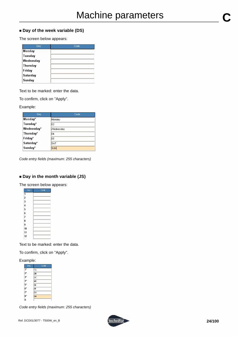
Day of the week variable (DS)The screen below appears:
Text to be marked: enter the data.
To confirm, click on "Apply".
Example:
Code entry fields (maximum: 255 characters)
Day in the month variable (JS)
The screen below appears:
Text to be marked: enter the data.
To confirm, click on "Apply".
Example:
Code entry fields (maximum: 255 characters)
Ref. DCD01/3077 - T500W_en_B 24/100

AMachine parameters C
Hour variable (HS)The screen below appears:
Text to be marked: enter the data.
To confirm, click on "Apply".
Example:
Code entry fields (maximum: 255 characters)
Ref. DCD01/3077 - T500W_en_B 25/100

AMachine parameters C
7. CCU memorySaving or loading files
Used to transfer marking files from the machine memory to the PC memory. There are two possiblities:
• UC => PC
• PC => UC
The screen below appears:
1 : Directory (PC)2 : Export a file (PC => UC)3 : CCU memory 4 : Selecting marking files (PC)5 : Import a file (UC => PC)6 : Delete a file (UC)
Export a file (PC => UC)
Select the directory in which to save the files to be transferred. The files present in the directory appear on the screen.
Select the files to be transferred. Click on the icon:
Import a file (UC => PC)
Select the files to be transferred. Only the ticked boxes are taken into account. Click on the icon:
Delete a file (UC)
Select the files to be deleted. Click on the icon:
1
3
4
5
62
Ref. DCD01/3077 - T500W_en_B 26/100

AMachine parameters C
Font managementUsed to transfer files between the machine’s Fonts have the PO3 format.
2 possibilities:
• UC => PC
• PC => UC
The screen below appears:
1 : Directory (PC)2 : Export a font (PC => UC)3 : CCU memory - This list indicates the fonts available in memory. Each font is identified by a number. 4 : Selecting a(n) PO3 file (PC)5 : Preview of the selected font 6 : Import a font (UC => PC)7 : Delete a font (UC)
Export a font (PC => UC)
Select a directory. The files present in the directory appear on the screen.
Select the files to be transferred. Click on the icon:
When a PO3 file is transferred in the CCU, a copy of this file is also created in the program’s shared files on the PC, for the graphic visualization. It is not possible to preview a PO3 file which is present in the CCU but not on the PC.
1
3
4
562
7
Ref. DCD01/3077 - T500W_en_B 27/100

AMachine parameters C
Import a font (UC => PC)Character fonts are programmed in the CCU board. The standard configuration comes with 3 fonts (pneumatic version).
If other fonts were ordered, they will also appear in this list.
The standard configuration fonts bear a number between 0 and 99. The additional fonts bear a number starting from 100. The standard configuration fonts cannot be exported, re-indexed nor deleted.
Select the files to be transferred. Only the ticked boxes are taken into account. Click on the icon:
Delete a font (UC)
Select the files to be deleted. Click on the icon:
Logo management
Used to transfer files between the machine’s Logos have the LO3 format.
2 possibilities:
• UC => PC
• PC => UC
The screen below appears:
1 : Directory (PC)2 : Export a logo (PC => UC)3 : CCU memory - This list indicates the available logos. Each logo is identified by a number. 4 : Selecting a(n) LO3 file (PC)5 : Preview of the selected logo 6 : Import a logo (UC => PC)7 : Delete a logo (UC)
1
3
4
562
7
Ref. DCD01/3077 - T500W_en_B 28/100

AMachine parameters C
Export a logo (PC => UC)Select a directory. The files present in the directory appear on the screen.
Select the files to be transferred. Click on the icon:
When a LO3 file is transferred in the CCU, a copy of this file is also created in the program’s shared files on the PC, for the graphic visualization. It is not possible to preview a LO3 file which is present in the CCU but not on the PC.
Import a logo (UC => PC)
Logos are programmed in the CCU board. The standard configuration comes with 2 logo(s).
If other logos were ordered, they will also appear in this list.
The standard configuration logos bear a number between 0 and 99. The additional logos bear a number starting from 100. The standard configuration logos cannot be exported, re-indexed nor deleted.
Select the files to be transferred. Only the ticked boxes are taken into account. Click on the icon:
Delete a logo (UC)
Select the files to be deleted. Click on the icon:
Ref. DCD01/3077 - T500W_en_B 29/100

DD"Marking" menu Select the type of marking in the "Marking" menu.
1. Standard marking
1 : Standard marking "one time" 2 : Standard marking "N times" 3 : "Infinite" standard marking 4 : Launch the marking cycle 5 : Stop the marking cycle
Marking "One time" (F10)
Used to send a file that is currently displayed on the computer screen to the marking machine for a "single" marking.
Marking "N times"
Used to mark the same marking file a set number of times Select the number of markings requested. The default value is 1.
"Infinite" marking
It is a marking mode similar to "N times" except that the marking is repeated infinitely.
3 2 1 4 5
Ref. DCD01/3077 - T500W_en_B 30/100

A"Marking" menu D
2. "Independent" marking"Infinite" independent marking
Used to launch marking in independent mode.
Used to obtain markings identical to those in "Infinite" mode, the only difference being that when the machine is switched back on after an interruption during marking (reset, power outage...) marking is resumed by clicking on "Start marking". The keyboard doesn’t have to be connected to resume marking.
The only command accepted is Marking - Independent - Cancel.
Cancel
Used to interrupt the independent marking session in progress.
3. Simulation
File simulation (F9)
Used to simulate the marking file. Simulation consists in performing the marking without activating the stylus.
Simulation is carried out as a "one time" marking.
Simulation of the current block (F4)
Used to carry out a marking simulation of the marking block under preparation. The simulation is carried out for just one block.
Ref. DCD01/3077 - T500W_en_B 31/100

A"Marking" menu D
4. Start-up markingDuring marking, the screen below appears:
1 : Launch the marking cycle 2 : Stop the marking cycle 3 : Number of markings carried out in relation to the total number of markings to be done
It is possible to pause during marking or to stop the latter by moving onto the corresponding icons.
"Preferences " - "Show the chronometer" - box ticked: used to display the marking time.
The chronometer stops and starts again when there is a pause. At the end of the marking, the screen indicates the marking time.
1
3
2
"Pause during marking" icon
Ref. DCD01/3077 - T500W_en_B 32/100

EE"Edit file" menu 2 cases may happen:
• open an existing file.
• create a new marking file.
Open an existing file
Click on the icon:
Create a new marking file
To create a new marking file, select the "File - New" menu or click on the corresponding icon in the tool bar.
When a file is created, an empty block appears on the screen. Linear marking is selected by default.
1 : Block number 2 : Block name (label) 3 : Type of marking 4 : Text to be marked 5 : X coordinate 6 : Y coordinate 7 : Character size 8 : File speed option 9 : Character font 10 : Movement speed 11 : Marking speed 12 : Marking quality 13 : Marking force (%)14 : Text angle 15 : Marking effects 16 : Alignment 17 : Marking direction 18 : Compression (%)19 : Spacing between characters (%)20 : Inclination
1 2 3 4 5 6 7
8 9 11 13 14 15 16 17 18 19 20 10 12
Ref. DCD01/3077 - T500W_en_B 33/100
A"Edit file" menu E
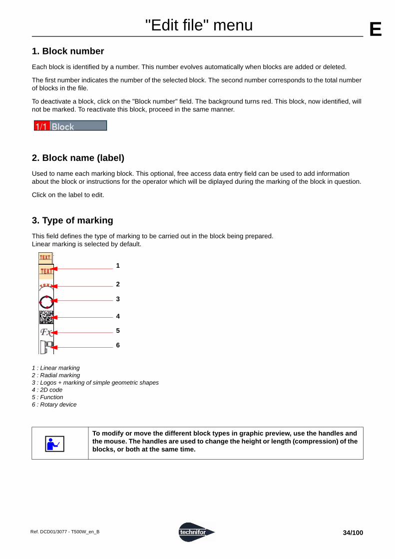
1. Block numberEach block is identified by a number. This number evolves automatically when blocks are added or deleted.
The first number indicates the number of the selected block. The second number corresponds to the total number of blocks in the file.
To deactivate a block, click on the "Block number" field. The background turns red. This block, now identified, will not be marked. To reactivate this block, proceed in the same manner.
2. Block name (label)
Used to name each marking block. This optional, free access data entry field can be used to add information about the block or instructions for the operator which will be diplayed during the marking of the block in question.
Click on the label to edit.
3. Type of marking
This field defines the type of marking to be carried out in the block being prepared. Linear marking is selected by default.
1 : Linear marking 2 : Radial marking 3 : Logos + marking of simple geometric shapes 4 : 2D code 5 : Function 6 : Rotary device
To modify or move the different block types in graphic preview, use the handles and the mouse. The handles are used to change the height or length (compression) of the blocks, or both at the same time.
1
2
3
4
5
6
Ref. DCD01/3077 - T500W_en_B 34/100

A"Edit file" menu E
Linear markingUsed to mark straight lines of text at an angle. The screen below appears:
Example
Use of the handles:
1 : Height 2 : Height + text length 3 : Text length 4 : Angle (used to define the angle at which the text is marked)
To obtain a marking parallel to the X axis, set the angle at 0° in the corresponding field.
To obtain a marking parallel to the Y axis, set the angle at 90°.
1
2
3
4
X
Y
0 10 20 30
10
20
30
0 X
Y
90°
0 10 200
10
Angle: 0° Angle: 90°
X
Y
45°
0 10 20 300
10
20
Angle: 45°
Ref. DCD01/3077 - T500W_en_B 35/100

A"Edit file" menu E
Radial markingUsed to obtain texts along the circumference of a circle.
The angle value in degrees corresponds to the positioning angle of the marking on the circle. The X-Y coordinates correspond to the center of the base circle for the marking.
The screen below appears:
1 : Marking direction 2 : Circle radius 3 : Initial angle
Example
Use of the handles: See: Linear marking
1 2 3
Ref. DCD01/3077 - T500W_en_B 36/100

A"Edit file" menu E
Clockwise marking / counter-clockwise markingIn radial marking mode, select the marking direction icon with the arrows in order to select clockwise or counter-clockwise marking or select the configuration wanted with the mouse. Clockwise marking is selected by default.
Special situation
It is possible that the center of the circle is located outside the marking zone. In this case, the X and Y coordinates are superior or inferior to the marking area. Check that the text to be marked is within the marking area.
Example of a circle outside the marking area:
1 : Marking area: 60 mm (2.362 in) x 40 mm (1.575 in) 2 : Angle: 160°3 : Radius: 30 mm (1.181 in)
Initial angle Clockwise marking Counter-clockwise marking
Angle: 90°Centering
Angle: 270°Centering
X
Y
90°
X
Y
90°
X
Y
270°
X
Y
270°
3
2
1
Ref. DCD01/3077 - T500W_en_B 37/100

A"Edit file" menu E
Marking of simple geometric shapesNote: pneumatic machines only
Used to mark logos, lines, circles...
Select the type of shape using the Up - Down arrows or select the configuration wanted with the mouse.
The text parameters (coordinates, size, etc...) are defined in this same block.
• Logos
The screen below appears:
Example
Use of the handles:
1 : Height 2 : Height + length 3 : Length 4 : Angle
The logo can be moved.
Note: create a new logo - See: Logo editor
1
2
3
4
Ref. DCD01/3077 - T500W_en_B 38/100

A"Edit file" menu E
• Circles (pneumatic machines only)Used to mark circles, ellipses, circle arcs.
1 : X-Y coordinates 2 : Radius in X 3 : Radius in Y 4 : Initial angle 5 : End angle
X-Y coordinates: the X-Y coordinates correspond to the center of the circle.
Example
Circle Ellipse Arc of a circle
Radius in X = Radius in Y Radius in X > Radius in Y Angle: < 360°
1 2 345
Ref. DCD01/3077 - T500W_en_B 39/100

A"Edit file" menu E
• Lines (pneumatic machines only)Used to mark one or several lines.
The screen below appears:
1 : Addition of a point at the end 2 : Insertion of a point at the current position 3 : Deletion of the point underway
It is possible to choose up to 16 points to establish one or several lines.
Examples
Note: To trace a rectangle, 5 points are required.
Square Rectangle Lines
1
2
3
Point X Y
1 10 10
2 20 10
3 20 20
4 10 20
5 10 10
Point X Y
1 10 10
2 30 10
3 30 20
4 10 20
5 10 10
Point X Y
1 10 10
2 20 10
3 20 20
Ref. DCD01/3077 - T500W_en_B 40/100

A"Edit file" menu E
2D codeUsed to mark DataMatrix codes.
When the "2D code" marking type is selected, choose the desired type of code. Select the configuration wanted with the mouse.
• DataMatrix
The screen below appears:
1 : Angle in degrees 2 : Cell size 3 : One way marking / return marking 4 : Text to be marked 5 : X-Y coordinates 6 : Size of the DataMatrix code (height)7 : Matrix format (rows x columns)
Angle: the value entered in this field determines the angle in degrees along which the DataMatrix code is marked.
1 : Angle in degrees
Cell size:
The size of the cells automatically adapts itself according to the size of the DataMatrix code and the matrix format.
To know the height of the cells which make up the code, divide the size of the code by the number of lines in the format selected.
Example 1: If:
- size of the DataMatrix code: 10 mm (0.394 in)- matrix format: 20 x 20
=> cell size: 10 mm (0.394 in)/20 = 0.5 mm (0.02 in)
Example 2: If:
- cell size = 0.67 mm (0.026 in)- matrix format: 20 x 20
=> size of the DataMatrix code: 0.67 mm (0.026 in) x 20 = 13.4 mm (0.528 in)
5 6 731 2 4
X
Y
0
1
1
2
1 : Size of the DataMatrix code 2 : Height of a cell in the DataMatrix code
Ref. DCD01/3077 - T500W_en_B 41/100

A"Edit file" menu E
One way marking / return marking:One way marking: The stylus always restarts from the left at the beginning of each line. It favors mark quality over speed.
Return marking: The stylus marks the first line of the code from left to right, then the second from right to left, etc... It favors the marking speed.
Select the configuration wanted with the mouse.
Text to be marked:
Insert the text to be encoded in DataMatrix.
X-Y coordinates:
The values entered in the X and Y fields determine the start position of the DataMatrix marking.
1 : The X represents the start marking point (X-Y coordinates).
Size of the DataMatrix code:
The value entered in this field defines the height of the DataMatrix code. This value automatically adapts itself according to the size of the cells and the matrix format.
1 : Size of the DataMatrix code
Note
To maintain a high marking quality, the angle value must be a multiple of 90° (0°, 90°, 180°, 270°).
Matrix format:
Determines the number of lines and columns contained in the DataMatrix code. Several pre-defined formats are available.
Select the configuration wanted with the mouse.
Choose the "Auto" format to have the program calculate automatically the number of lines and columns necessary to encode the text to be marked.
0 X
Y
10
50 X
1
0 X
Y
1
Ref. DCD01/3077 - T500W_en_B 42/100

A"Edit file" menu E
FunctionUsed to access to certain automation functions, operations on the variables, etc.
The screen below appears:
When the "Function" marking type is selected, choose the desired type of function.
Select the configuration wanted with the mouse.
• Branch (UC500)
(option available on machines UC500 only)
Used to define coding Inputs to select the files to be marked.
The marking program uses information transmitted via the 8I / 4O board.
The objective is to mark a file number "n", using a special instruction to request it. This instruction is defined in the "main file". The "main file" must be saved in the CCU. The "main file" can be marked in independent mode.
All files to be used with the I/O function must be saved under a number.
The screen below appears:
1 : Start Input (First Input) 2 : End Input (Last Input)
• First Input: number of the first Input used to code the number of the file to be marked
• Last Input: number of the last Input used to code the number of the file to be marked
Select the configuration wanted with the mouse.
Some functions are optional, depending on the marking machine used.
1 2
Ref. DCD01/3077 - T500W_en_B 43/100

A"Edit file" menu E
During marking of a "main file", when the program encounters the BRANCH instruction, it recalls and marks the contents of the file whose number results from the coding operation.Once the BRANCH instruction has been executed, the program returns to normal marking of the "main file".
Codifying Inputs:
The Input values (0 or 1) comprised between First Input and Last Input represent the binary number, converted to decimal, to obtain the file number.
The number of addressable files corresponds to the formula: 2n (n = number of coding Inputs). n = (Last Input - First Input) + 1
Example:
The screen below appears:
On the previous screen, the Inputs # 0 - 1 - 2 are used. For these 3 Inputs, the number of addressable files is: 2³ = 8 distinct files, following the table below:
Using the BRANCH instruction with the program:
The BRANCH instruction is part of the "main file". The "main file" is considered part of the "calling program". The "main file" may contain instructions other than the BRANCH instruction, and may execute markings different from those contained in the BRANCH instruction.
Refer to the user manual for the T05 program: "Index a file "
During a marking cycle, the program:
• orders the marking of blocks, following the sequence defined in the "main file".
• recalls and analyzes the file designated by the BRANCH instruction, then orders the marking of the selected file each time it encounters this instruction.
• sends the order to resume marking the blocks in the "main file".
Input number Number of the selected file
I2 I1 I0
Inp
ut
stat
us
0 0 0 0
0 0 1 1
0 1 0 2
0 1 1 3
1 0 0 4
1 0 1 5
1 1 0 6
1 1 1 7
Ref. DCD01/3077 - T500W_en_B 44/100

A"Edit file" menu E
Example:Data:
• Main file containing 4 marking blocks
• Block 3 contains a BRANCH instruction in which 4 files are codified.
• The coding Inputs are the numbers 0 - 1.
• The executable files are defined by numbers 0, 1, 2, 3. Refer to the user manual for the T05 program: "Index a file "
1 : Run file number "n", following the Input combination I0 and I1. Return to the "main file" when finished. 2 : Generates "End of marking" signal
0 1 2 3
...
...
...
...
Main file
Block 1
Block 2
Block 3 BRANCH: I0 to I1
Block 4 Block 1 Block 2 ......Block n
Block 1 Block 2 ......Block n
Block 1 Block 2 ......Block n
Block 1 Block 2 ......Block n 2
1
Ref. DCD01/3077 - T500W_en_B 45/100

A"Edit file" menu E
• CsvList (optional)Used to extract data from .csv files (processing the file line by line).
The screen below appears:
1 : Setting the batch number 2 : File name 3 : Selecting the field separator 4 : Number of line to start 5 : Delete the line used 6 : Add a marker 7 : Marker of the line used 8 : Read column 9 : Number of the variable 10 : File variable(s)
Import the file into the machine (refer to the user manual for the T05 program).
Indicate the name of the file to be used. This field may contain set text, key words (date, hour...), the content of a counter, etc.
Select the field separator.
Number of line to start: select the start line where the search starts.
Delete the line used: box ticked - the line is deleted from the file after use.
Add a marker: box ticked - a marker is added to the end of the line after use.
Marker of the line used: select the end-of-line marker to use.
Read column: select the column containing the data to use.
Number of the variable: number of the variable in which is memorized the character string
File variable(s): box ticked - held in memory in the file variables / box not ticked - held in memory in the machine variables
1 32 4 6 7 85 9 10
Ref. DCD01/3077 - T500W_en_B 46/100
A"Edit file" menu E
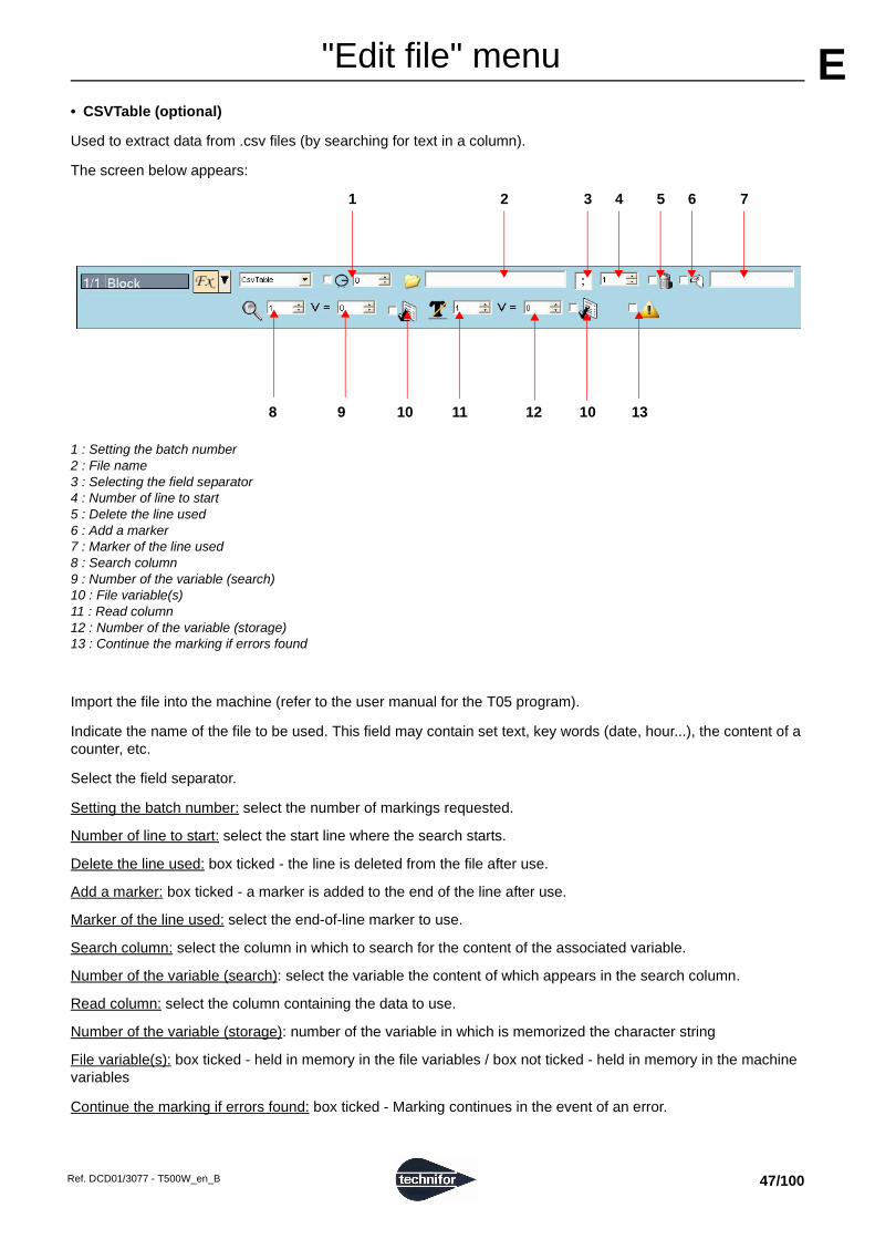
• CSVTable (optional)Used to extract data from .csv files (by searching for text in a column).
The screen below appears:
1 : Setting the batch number 2 : File name 3 : Selecting the field separator 4 : Number of line to start 5 : Delete the line used 6 : Add a marker 7 : Marker of the line used 8 : Search column 9 : Number of the variable (search)10 : File variable(s) 11 : Read column 12 : Number of the variable (storage)13 : Continue the marking if errors found
Import the file into the machine (refer to the user manual for the T05 program).
Indicate the name of the file to be used. This field may contain set text, key words (date, hour...), the content of a counter, etc.
Select the field separator.
Setting the batch number: select the number of markings requested.
Number of line to start: select the start line where the search starts.
Delete the line used: box ticked - the line is deleted from the file after use.
Add a marker: box ticked - a marker is added to the end of the line after use.
Marker of the line used: select the end-of-line marker to use.
Search column: select the column in which to search for the content of the associated variable.
Number of the variable (search): select the variable the content of which appears in the search column.
Read column: select the column containing the data to use.
Number of the variable (storage): number of the variable in which is memorized the character string
File variable(s): box ticked - held in memory in the file variables / box not ticked - held in memory in the machine variables
Continue the marking if errors found: box ticked - Marking continues in the event of an error.
8 109 11 12 10 13
1 2 3 4 5 6 7
Ref. DCD01/3077 - T500W_en_B 47/100

A"Edit file" menu E
• Default
Used to display an on-screen information message explaining why marking has been interrupted, for example because of a non-fulfilled condition (IF function).
The screen below appears:
Enter the text to be displayed when marking reaches a Default block. This field may contain set text, key words (date, hour...), the content of a counter, etc.
A window opens to acknowledge this fault. Marking is interrupted.
• Delay
This instruction is used to program a pause between the marking of two consecutive marking blocks. The time is expressed in milliseconds.
The screen below appears:
The machine waits the time shown before going on to the following block.
Text to be displayed
Pause time in milliseconds
Ref. DCD01/3077 - T500W_en_B 48/100

A"Edit file" menu E
• DialogYesNoUsed to display a question on the screen requiring a yes or no answer.
The marking of a file containing a block with DialogYesNo function cannot be launched from the T500W program.
The screen below appears:
1 : Question to be displayed 2 : Number of block to reach (negative answer)
When the question appears, answer:
- Yes: The file marking continues normally. - No: The program immediately starts marking the block indicated.
You cannot indicate an earlier block number in the file (no going backwards). To reach the end of the file, enter the value 0.
• GoToBlock
Used to go directly to the required block in the same marking file.
The screen below appears:
The program immediately starts marking the block indicated. You cannot indicate an earlier block number in the file (no going backwards). To reach the end of the file, enter the value 0.
1 2
Number of block to reach
Ref. DCD01/3077 - T500W_en_B 49/100

A"Edit file" menu E
• If (standard or optional, depending on the machine type)Used to add a condition for marking the file. The screen below appears:
1 : Type of condition 2 : Values to compare 3 : Number of block to reach (if the condition is not fulfilled)4 : Type of comparator
Type of condition: select the condition type.
- TEXT COMP: comparing 2 text fields - This field may contain set text, key words (date, hour...), the content of a counter, etc.
Values to compare: input the values to compare. This field may contain set text, key words (date, hour...), the content of a counter, etc.
Number of block to reach (if the condition is not fulfilled):
- if the condition is not fulfilled: the program immediately starts marking the block indicated. You cannot indicate an earlier block number in the file (no going backwards). To reach the end of the file, enter the value 0.
- if the condition is fulfilled: the file marking continues normally.
Type of comparator: select the type of comparator for the 2 values.
1 2 3
4
Ref. DCD01/3077 - T500W_en_B 50/100

A"Edit file" menu E
• OffsetUsed to shift the coordinates of one or more blocks.
The screen below appears:
1 : Offset type 2 : Number of markings to execute 3 : Number of blocks involved 4 : X-Y reference coordinate(s)
X-Y reference coordinate(s): Xr - Yr = coordinates of the point where the stylus will be positioned - The offset is calculated based on these coordinates.
Number of blocks involved: used to define the number of blocks involved in this function.
Number of markings to execute: used to define to how many markings this function applies.
Offset type: select the required input mode.
- Adjustment: define the new X-Y coordinates using the arrow keys on the numeric keypad.
- Entry: enter the new X-Y coordinates via the keyboard at the time of marking.
- Fixed: two new data entry fields appear on the screen.
Enter the new X-Y coordinates in these fields.
Used to specify the offset based on variable(s) by using the "Var XY" function in the preceding block.
• PN Chuck (optional)
This opens and closes the pneumatic chuck of the rotary device.
The screen below appears:
Select the option required.
431 2
Ref. DCD01/3077 - T500W_en_B 51/100

A"Edit file" menu E
• SetOutput (UC500)Used to specify the state of the Outputs. The screen below appears:
Click on the arrow to view the drop down menu.
Select the configuration wanted with the mouse. Repeat for each output if necessary.
x current state
0 goes to state 0
1 goes to state 1
complementary with the actual state
Ref. DCD01/3077 - T500W_en_B 52/100

A"Edit file" menu E
• VarBranch (standard or optional, depending on the machine type)Used to select a file based on the content of a variable.
The screen below appears:
1 : Number of the variable 2 : File variable(s) 3 : Selection by name 4 : Selection by ID
Number of the variable: variable from which to retrieve the file name or number
File variable(s): box ticked - held in memory in the file variables / box not ticked - held in memory in the machine variables
Selection by name / selection by ID: you can select the files by ID (number) or by name. Choose the type of selection.
If you select by ID, index the files to be used. Refer to the user manual for the T05 program: "Index a file "
• Var in
Allows the reception in a variable of a new character string via the RS232 communication, directly on the machine.
The screen below appears:
1 : Input method 2 : Number of the variable in which is memorized the character string 3 : File variable(s) 4 : Batch: number of markings to be carried out with this variable before proposing to re-program the variable 5 : Checksum 6 : Timeout
Select the data input method (RS232, keyboard).
The marking of a file containing a block with "Var in" function cannot be launched from the T500W program.
1 2 43
1 2 3 4 5 6
Ref. DCD01/3077 - T500W_en_B 53/100

A"Edit file" menu E
Select the number of the variable in which is memorized the character string received.Select the type of variable (file variable(s) / machine variable(s)).
Choose the number of markings that have to be made before the reception of the following data:
• 0: data reception required once at the first marking (even if the file is to be marked several times).
• 1: data reception required at each marking.
• >1: every x markings
During the marking of a "Var in" block, the machine emits an data acquisition request (U<CR>) on the RS232 communication and expects an answer from the connected peripheral.
The peripheral must answer by a series of bytes ending by <CR>.
The machine answers V<CR> if successful or T<CR> if failed. If successful, the character string is stocked in the specified variable. If failed, the machine waits for a new data transmission.
The data acquisition has succeeded when the checksum received is equal to the checksum calculated or when the checksum is not used.
The checksum is added at the end of the message. It is represented by 2 consecutive characters (0 to F, in hexadecimal mode).
The emitter calculates the checksum based on the useful data in the transmitted message. The receiver also calculates the checksum based on the useful data transmitted, and compares this new checksum to the one received.
The checksum is calculated using an "exclusive Or" (XOR) between all the characters contained in the useful part of the message.
• emission checksum = "character 1 emitted" XOR "character 2 emitted" XOR ... "character n emitted"
• receiving checksum = "character 1 received" XOR "character 2 received" XOR ..."character n received"
Example
Given the message "ABCD": Checksum calculation: 65 XOR 66 XOR 67 XOR 68
The result of the message ABCD is: 00000100 in binary, or 04 in hexadecimal mode. The emitter sends the message ABCD04.
Calculation Characters Decimal Binary Result
A 65 01000001
XOR B 66 01000010
00000011
XOR C 67 01000011
01000000
XOR D 68 01000100
00000100
Ref. DCD01/3077 - T500W_en_B 54/100

A"Edit file" menu E
It is possible to activate the timeout. Two new data entry fields appear on the screen.1 : Waiting time (s)2 : Number of block to reach
If the data is not received within the waiting time indicated: the program immediately starts marking the block indicated. You cannot indicate an earlier block number in the file (no going backwards). To reach the end of the file, enter the value 0.
Var in: use in a marking file
Example:
The text is saved in variable V2. Only the character string included between characters 1 and 4 is marked.
A request for data acquisition is necessary each time the file is marked because the batch is set at 1.
Use with the machine’s internal program:
• Transfer marking files, programmed in a PC, to the marking machine (RS232 link).
• Disconnect PC/machine link.
• The "Raw data" box must be ticked in the "Communication" menu - "Serial management". Refer to the user manual for the T05 program.
• Choose the file to be marked.
• Launch the marking cycle.
1 2
Block 1:
Block 2:
Ref. DCD01/3077 - T500W_en_B 55/100

A"Edit file" menu E
• VarInPCFunction identical to VarIn
The screen below appears:
1 : Number of the variable in which is memorized the character string 2 : Batch: number of markings to be carried out with this variable before proposing to re-program the variable 3 : Entering text in a selected variable
In the VarInPC function, the only acquisition device possible is the PC keyboard.
See: Var in
• VarOut
Used to send a character string contained in a variable using a RS232 connection.
The screen below appears:
1 : Number of the variable 2 : File variable(s) 3 : Activate / deactivate the carriage return (code 13) at the end of the string.
Select the number of the variable containing the character string to be sent.
Select the type of variable (file variable(s) / machine variable(s)).
Activate / deactivate the carriage return (code 13) at the end of the string: box ticked - this character is appended to the end of the character string.
The marking of a file containing a block with the VarInPC function can only be launched from the T500W program.
The marking of a file containing a block with "Var Out" function cannot be launched from the T500W program.
1 2 3
1 32
Ref. DCD01/3077 - T500W_en_B 56/100

A"Edit file" menu E
• VarSetUsed to memorize a character string in a variable.
The screen below appears:
1 : Number of the variable in which is memorized the character string 2 : File variable(s) 3 : Entering text in a selected variable
Select the type of variable (file variable(s) / machine variable(s)).
This field may contain set text, key words (date, hour...), the content of a counter, etc.
Example:
To mark the memorized content in the V1 variable, create a linear marking block containing the keyword V1. See: "Key words"Marking obtained: Date 05 11 07 001
• Var XY
Used to assign the content of a variable to a coordinate for the subsequent block(s).
The screen below appears:
1 : Activate / deactivate the coordinates 2 : File variable(s) 3 : Number of the variable 4 : Number of blocks involved
Activate / deactivate the coordinates: select the coordinate(s) to which to assign the content of a variable.
File variable(s): select the type of variable (file variable(s) / machine variable(s)).
Number of the variable: number of the variable the content of which is assigned to a coordinate
Number of blocks involved: used to define the number of blocks involved in this function.
1 2 3
14
2
3
Ref. DCD01/3077 - T500W_en_B 57/100

A"Edit file" menu E
• Wait Input (UC500)Waits for the state of one or more Inputs in order to move to the following marking block.
The screen below appears:
1 : Input number 2 : Timeout
The number of Inputs goes from left to right. Click on the Input wanted. With the +/- keys of the numeric keypad, select the state of the Input to wait (0, 1 or not-taking into account). Start over for each area if necessary.
When the program meets this type of block, it waits for the state of the Inputs corresponding to the one which is indicated in the block, before marking the following block.
Example:
The program marks the following block only when:
• I 0 = 0
• I 2 = 1
• I 7 = 1
It is possible to activate the timeout. Two new data entry fields appear on the screen.
1 : Waiting time (s)2 : Number of block to reach
If the data is not received within the waiting time indicated: The program immediately starts marking the block indicated. You cannot indicate an earlier block number in the file (no going backwards). To reach the end of the file, enter the value 0.
01234567
1 2
1 2
Ref. DCD01/3077 - T500W_en_B 58/100

A"Edit file" menu E
• Write line (optional)Used to write a line of text to a log file.
The screen below appears:
1 : File format 2 : Text to write to the file 3 : File name 4 : Maximum number of lines in the file
Select the file format:
• ASCII: characters between 32 and 127
• UTF-8
• HEADER + UTF-8: with UTF-8 header in 3 characters
Text: this field may contain set text, key words (date, hour...), the content of a counter, etc.
File name: this field may contain set text, key words (date, hour...), the content of a counter, etc.
Select the maximum number of lines in the file.
• When the indicated number of lines is reached, the oldest line is deleted.
• When 0 is selected, the new line is added at the end without restriction.
1 2 43
Ref. DCD01/3077 - T500W_en_B 59/100

A"Edit file" menu E
Rotary device (optional)Used to mark cylindrical parts thanks to a rotary marking device.
Depending on the type of machine, all options are available.
1 : Initial angle 2 : Part radius 3 : Number of characters per batch 4 : Writing direction on the rotary device 5 : Rotary device rotation direction 6 : Marking direction
Number of characters per batch: indicate the number of characters to be marked before rotation of the axis.
Writing direction on the rotary device: used to determine character orientation.
Rotary device rotation direction: clockwise / counter-clockwise
Marking direction: used to choose the movement direction of the stylus during marking, from left to right or from right to left.
Rotary device positionned on the origin side
Clockwise Counter-clockwise
1 2 3 4 5 6
Ref. DCD01/3077 - T500W_en_B 60/100

A"Edit file" menu E
4. Text to be markedEnter the text to be marked in the appropriate block. The text may be composed of:
• capital / lower case letters
• numbers
• key words
• logos
The maximum number of characters per block is 255. The characters that can be marked depend on the font.
Note: To mark the "double quotation marks" character, enter it twice.
List of key words
Key words Definition Marking
DD number of the day in the month (from 01 to 31) 09 - for the 9th day in the month
MM month number (01 to 12) 05 - for the month of May
YYYY year in 4 digit(s) 2007
YY year in 2 digit(s) 07
Y year in 1 digit(s) 7
hh hours (00 to 23) 12 - for 12 h 28 min 35 sec
mm minutes (00 to 59) 28 - for 12 h 28 min 35 sec
m first number for block of ten minutes (1 to 5) 2 - for 12 h 28 min 35 sec
ss seconds (00 to 59) 35 - for 12 h 28 min 35 sec
WW week number (01 to 53) 01 - for January 3 2001
CCC number of the day in the year (001 to 366) 028 - for January 28 2001
HS time interpretation code
DS interpretation code for the day of the week
JS interpretation code for the day of the month
MS interpretation code for the month
YS interpretation code for the year
Kn interpretation code for the counters (0 to 9)
Q interpretation code for shifts according to time block
Vn interpretation code for variables
Vm last text marked
Fx connection to a data base
Ref. DCD01/3077 - T500W_en_B 61/100

A"Edit file" menu E
Key wordsKey words are codes interpreted by the program. They are not actually marked but rather "recorded" before marking.
It is possible to define several keywords in the same text area.
To enter a keyword, press the Insert key on the keyboard in the "Text" area. The list of keywords appears.
Select the key word wanted with the Up - Down arrows, by entering the first letter of the key word to insert or by clicking on it with the mouse. Validate by pressing Enter or click on "OK".
The keywords are indivisible units. When a keyword is inserted, it appears in a frame, it is impossible to delete part of akeyword. Each keyword is considered a single character.
For Vn - FVn - Kn - FKn - Fx keywords, a second window appears to select the variable number.
Select the number in the drop down list. Click on "OK".
Ref. DCD01/3077 - T500W_en_B 62/100

A"Edit file" menu E
Splitting a variableA portion of the contents of a variable may be selected and marked.
Tick the "Substring of the variable" box. The screen below appears:
1 : Efirst: first character to be included 2 : Elast: last character to be included
To mark a section of the variable content, indicate the first and last character to be taken into account.
Select any symbols before and after the numbers of the characters.
Characters
Possible values Meaning Note
N N character 0 < N < 256
0 last character
0! last character (not included)
&u first character for which the Unicode is u
0 < u < 65536
&u! first character for which the Unicode is u (not included)
#u last character for which the Unicode is u
#u! last character for which the Unicode is u (not included)
%u first character for which the Unicode is not u
%u! first character for which the Unicode is not u (not included)
*u last character for which the Unicode is not u
*u! last character for which the Unicode is not u (not included)
1 2
Ref. DCD01/3077 - T500W_en_B 63/100

A"Edit file" menu E
Example:Contents of variable V3: "7 0 2$ 4b00z"
Marking obtained: " 0 2$ "
It is possible to mark the content of a variable from right to left.
The 0 number represents the end of the variable.
Note: If it is not possible to determine the result (string too short, character sought absent, etc.), the result is an empty string.
Characters: 7 Space 0 2 $ Space 4 b 0 0 z
Code: Unicode 55 32 48 8364 50 36 32 52 98 48 48 122
Examples Result
V0[ ] 7 0 2$ 4b00z
V0[1;0] 7 0 2$ 4b00z
V0[0!;1] 00b4 $2 0 7
V0[4;10] 2$ 4b0
V0[8;3] 4 $2 0
V0[&50;10] 2$ 4b0
V0[&50;&98!] 2$ 4
V0[&48;0] 0 2$ 4b00z
V0[4;&98] 2$ 4b
V0[#32!;0] 4b00z
V0[%55!;*122] 0 2$ 4b00
V0[&8364!;*122!] 2$ 4b0
Ref. DCD01/3077 - T500W_en_B 64/100

A"Edit file" menu E
5. Properties of the fileTo access the general parameters of the file, press the F12 key.
1 : XY head marking speed 2 : File variable(s) 3 : Rotary device speed 4 : File counter(s)
XY head marking speed
TAB 1:
Used to determine the speeds common to the whole file. These speeds are applied by default to every block on the file.
The screen below appears:
1 3
2 4
Ref. DCD01/3077 - T500W_en_B 65/100

A"Edit file" menu E
TAB 2:Used to configure the return to origin of the stylus. The screen below appears:
1 : Number of markings before return to origin 2 : Return to origin at the beginning/end of the file 3 : Return to origin type 4 : Accurate mode / fast mode
Number of markings before return to origin: used to define the number of markings the stylus returns to origin.
If the 1 value is selected, the stylus returns to origin after each marking. If the 0 value is selected, the stylus never returns to origin, except when the machine is turned on. If the value 3 is selected, the stylus returns to origin after 3 markings.
Return to origin at the beginning/end of the file: used to define at which moment the stylus returns to origin in relation to the marking of a file. The return to origin at the end of a file is selected by default.
Return to origin type: used to select the stylus’ trajectory to return to origin.
• X, Y: following the X then the Y axis
• X & Y: following the X and Y axis at the same time (diagonal) to save cycle time
• Y, X: following the Y then the X axis
Depending on the type of machine, all options are available.
Accurate mode / fast mode: used to define the accuracy of the return to origin.
Accurate mode: when the origin position is reached (X and Y sensors activated), the stylus leaves this initial position to use once again a slow approaching speed. => searching the origin position with accuracy
Fast mode: origin position is reached in fast speed (X and Y detectors activated) without a to-and-from cycle in slow speed. => return to origin less accurate but time is saved
1
2
3
4
Ref. DCD01/3077 - T500W_en_B 66/100

A"Edit file" menu E
File variable(s)Used to mark repetitive texts common to several marking blocks in the same file, by indicating the variable number in which the text is contained.
Variables are memory blocks (5 in all) of text containing up to 255 characters. They are identified by the key words FV0 to FV4.
The screen below appears:
Select the desired variable. Enter the data.
To confirm, click on "Apply".
Remarks: Unlike the machine variables, these variables are specific to each marking file. They function in an identical way. See: "Configuring variables (machine variable(s))"
Use machine variables where possible, since file variables increase the file size.
To insert a key word and its number: See: "Text to be marked".
Rotary device speed
TAB 1:
Used to determine the movement speed of the rotary device. The screen below appears:
Ref. DCD01/3077 - T500W_en_B 67/100

A"Edit file" menu E
TAB 2:Used to configurate the return to origin of the rotary device. The screen below appears:
1 : Number of markings before return to origin 2 : Return to origin at the beginning/end of the file 3 : Return to origin type
Number of markings before return to origin: used to define after how many markings the rotary device returns to origin. If the 1 value is selected, the rotary device returns to origin after each marking.
Return to origin at the beginning/end of the file: used to define the moment the rotary device will return to origin in relation to the marking of a file.
The return to origin at the end of a file is selected by default.
Return to origin type: used to choose the rotation direction of the rotary device to return to origin.
- clockwise - counter-clockwise - fast: shortest travel distance in relation to the current position
2
3
1
Ref. DCD01/3077 - T500W_en_B 68/100

A"Edit file" menu E
TAB 3:Used to select the rotary device orientation in relation to the marking head. The screen below appears:
Select the configuration wanted with the mouse.
Example
1 : Rotary device on the X axis motor to the left 2 : Rotary device on the Y axis motor at the bottom (integrable version marking head)3 : Rotary device on the X axis motor to the left 4 : Rotary device on the Y axis motor at the top (integrable version marking head)
Select rotary device orientation corresponding to its installation.
Correctly select the rotary device position: the configuration selection directly influences the marking’s orientation on the part.
Head
Ref. DCD01/3077 - T500W_en_B 69/100

A"Edit file" menu E
File counter(s)Used to define increments/decrements for a serial number.
The screen below appears:
Select the desired number of counters. The corresponding counters appear on the screen.
Select the desired counter.
The data is in numeric, alphabetic, alphanumeric or hexadecimal mode. 5 independent counters are available. Each counter has an 8 digit code.
Identification key words go from FK0 to FK4.
Remarks:
• Unlike the machine counters, these counters are specific to each marking file. They function in an iden-tical way. See: "Configuring counters (Machine counter(s))"
• Use machine counters where possible, since file counters increase the file size.
• It is not possible to insert a file counter into a block if no file counter has been defined for the current file.
To insert a key word and its number: See: "Text to be marked".
Ref. DCD01/3077 - T500W_en_B 70/100

A"Edit file" menu E
6. Example of a fileFor this example, create a file composed of 5 marking blocks.
Only the details of the block being edited appear on the screen.
Marking preview
Text in red is off-limits.
Text in blue means the block is deactivated.
Text in green means that the text can be edited by the operator.
Ref. DCD01/3077 - T500W_en_B 71/100

A"Edit file" menu E
7. Conversion of the units into inchesThe marking program works in both millimeters and inches. All values pertaining to length are expressed in the chosen unit.
Files are created by default in millimeters. To create/open files in inches, tick the option in the following menu:
Changing from mm to inches automatically converts all values contained in the marking files.
8. Multiple file editing
Used to edit several files at the same time.
In this example, 2 files are open: f1 - f2. Click on the corresponding tab.
Ctrl + C - Ctrl + X / Ctrl + V: Used to copy/paste blocks from one file to another.
Ref. DCD01/3077 - T500W_en_B 72/100

FFTools The screen below appears:
1. Conversion of old file formats
Used to convert files from previous-generation machines (.200 - .201 format) to the new format.
CAUTION: depending on the machine’s generation, machines don’t work the same way. Check that each file is converted.
For the conversion, click on the "Tools - Convert files" menu.
The screen below appears:
1 : Select the extention of old (.200 - .201) files. 2 : Directory (search)3 : Select the files from the file tree structure. 4 : Select a destination folder for the files converted to the tml format. 5 : Click on the arrow to launch conversion.
Error messages due to incompatibility may appear after the conversion. These messages can be saved.
Depending on the version or complexity of the file, shapes may not be correctly converted. Some manual alterations may be necessary.
2
34
5
1
Ref. DCD01/3077 - T500W_en_B 73/100

ATools F
2. Logo editorUsed to access a mini logo edition tool.
Menu bar
No open logo Open logo
Ref. DCD01/3077 - T500W_en_B 74/100

ATools F
ToolbarA tool bar is used to quickly access the most frequently-used functions.
1 : Create a new logo (LO3 - PLT)2 : Open a logo (LO3 - PLT)3 : Save 4 : Conversion of files from .plt format to .lo3 format 5 : Dot by dot logo (CAUTION: irreversible operation)6 : Zoom out / zoom in 7 : Undo / redo 8 : Select an image as background. 9 : Shortcuts to some functions in the program 10 : Quit 11 : Logo name 12 : Size
Editing tools:
13 : Selection 14 : Insert a point 15 : Add points 16 : Ellipse 17 : Rectangle 18 : Pencil 19 : Delete
• Create a new logo (Ctrl + N)
The screen below appears:
Select the logo type: LO3 - PLT. The LO3 format is specially optimized for this type of machine. Enter the dimensions of the file. Click on "OK".
1211987654321
19
181716151413
10
Ref. DCD01/3077 - T500W_en_B 75/100

ATools F
• Open a logo (Ctrl + O)The screen below appears:
1 : Reader 2 : Directory 3 : Logo format 4 : Logo preview
Select a directory. Select the logo type: LO3 - PLT. If the selected file contains logos in the chosen format, an overview of the logos appears on the screen.
Select the logo. Click on the logo to view its size. Double-click on the logo to open it.
The screen below appears:
• Save (Ctrl + S)
Select the directory into which the logo currently being edited will be saved. After saving, the name appears in the "Name" field in the toolbar.
1
2
3
4
Ref. DCD01/3077 - T500W_en_B 76/100
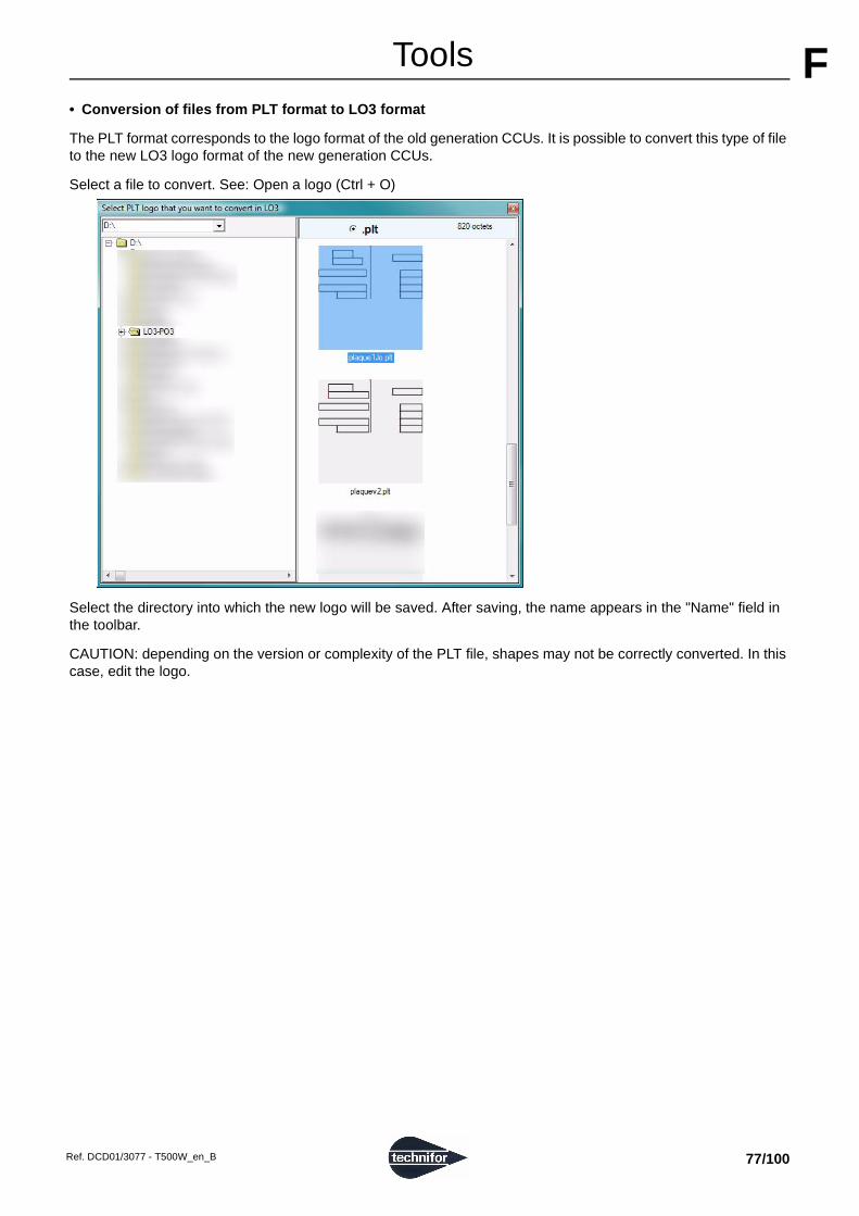
ATools F
• Conversion of files from PLT format to LO3 formatThe PLT format corresponds to the logo format of the old generation CCUs. It is possible to convert this type of file to the new LO3 logo format of the new generation CCUs.
Select a file to convert. See: Open a logo (Ctrl + O)
Select the directory into which the new logo will be saved. After saving, the name appears in the "Name" field in the toolbar.
CAUTION: depending on the version or complexity of the PLT file, shapes may not be correctly converted. In this case, edit the logo.
Ref. DCD01/3077 - T500W_en_B 77/100

ATools F
• Dot by dot logoWhen a LO3 logo is in continuous stroke, each point of a line is linked to the previous one by a segment. These segments appear during marking. A dot by dot LO3 logo no longer has these segments. The marking consists only of impact points at varying distances.
It is possible to convert a continuous stroke LO3 logo into a dot by dot LO3 logo.
Dot by dot logos are specially adapted for electromagnetic machines.
Select a file to convert. See: Open a logo (Ctrl + O)
Select the directory into which the new logo will be saved. The backup name has the header "ppp" (dot by dot).
Select the value "Delta" corresponding to the density and the distance between points (1 to 10). The higher this value, the lower the density and the greater the distance between each point.
Click on "OK".
After saving, the name appears in the "Name" field in the toolbar.
• Zoom out (Ctrl + -) / zoom in (Ctrl + +)
In high zoom, a grid appears. Display/hide the grid: Ctrl + G
Ref. DCD01/3077 - T500W_en_B 78/100

ATools F
• Undo (Ctrl + Z) / redo (Ctrl + Y)All changes made to the logo currently being edited is recorded in a history log. It is possible to undo/redo one or more previous changes.
• Select an image as background (Ctrl + P)
Used to insert a layer image behind the edit area.
Select the file (BMP - GIF - JPG format).
Once the image is selected, it is possible to set parameters for its position, size and opacity.
1 : Top edge of the image (pixels) - The default value is 0. 2 : Left edge of the image (pixels) - The default value is 0.
Note: The top left corner of the edit area corresponds to the origin point (0,0). 3 : Width (pixels) - The default value is that of the selected image. 4 : Height (pixels) - The default value is that of the selected image. 5 : Setting the transparency of the image (0 - 10) - The default value is 10.
Note: The higher the value, the more opaque the image. When the value is 0, the image is completely transparent.
Select the configuration wanted with the mouse. Click on "OK".
Cancel: the values taken into account are the default values.
The image appears in the background with the selected values.
1 2 3 4
5
Ref. DCD01/3077 - T500W_en_B 79/100

ATools F
• Shortcuts to some functions in the programLine
• Ctrl + Numeric keypad: Move
• Ctrl + Space: Select following
• Ctrl + Delete: Delete
• Ctrl + Page Up - Page Down: Rotation (clockwise - counter-clockwise)
Point
• Numeric keypad: Move
• Space: Select following
• Delete: Delete
Open logo
• S: Selection mode
• Insert: Insertion point mode
• A: Add point mode
• E: Ellipse mode
• R: Rectangle mode
• F: Free hand mode
General
• Ctrl + +: Zoom in
• Ctrl + -: Zoom out
• Ctrl + G: Display/hide the grid
• Ctrl + H: Display/hide the background image
• Ctrl + N: Create a new logo
• Ctrl + O: Open a logo
• Ctrl + P: Insert background image
• Ctrl + S: Save
• Ctrl + W: Quit
• Ctrl + Y: Redo
• Ctrl + Z: Undo
Ref. DCD01/3077 - T500W_en_B 80/100

ATools F
• Quit (Ctrl + W)Open logo: close the logo. A backup request appears.
No open logo: quit
• Logo name
Name of logo currently being edited + format (PLT - LO3)
• Size
The width and height in pixels of the logo currently being edited are displayed for information (non-editable).
Editing tools
• Selection
Click on a line or a point to select it. Click on a blank area to deselect all.
Cursor: Windows® arrow by default
• Insert a point
Used to insert a point on an existing and selected line.
Cursor: thin vertical arrow pointing upward
Ref. DCD01/3077 - T500W_en_B 81/100

ATools F
• Add pointsUsed to add a point:
- following an existing line if it is selected - a segment links the last point of the line to the newly created point. - as the first point of a new line
• Ellipse
Used to draw an ellipse. Click and drag the mouse while holding the left button down.
Cursor: cross
Ref. DCD01/3077 - T500W_en_B 82/100

ATools F
• RectangleUsed to draw a rectangle. Click and drag the mouse while holding the left button down.
Cursor: cross
• Pencil
Used to draw a line free hand. Click and drag the mouse while holding the left button down.
Cursor: cross
• Delete
Used to delete a selected line or point. Select the point or line to be deleted. Click on the corresponding icon.
Ref. DCD01/3077 - T500W_en_B 83/100

ATools F
3. BlockThe screen below appears:
Add a block at the end of the file (F5)
Used to add "empty" marking blocks at the end of a file. The program then automatically updates the numbering.
Deleting the selected block (Delete)
Deletes a marking block
As a precaution, the program will request confirmation before deleting the marking block.
Copy a block (F7)
Used to add a block identical to the selected block. The program copies and inserts this new block after the selected block, then updates the numbering.
Insertion of a block before the selected block (Insert)
Used to insert an "empty" block before the seleted block.
The program then automatically updates the numbering.
Activation / deactivation of the blocks (Space)
Used to deactivate a block from a marking file. A deactivated block is not marked.
Position on the chosen block. In the menu, click on the corresponding function.
Deactivated block
To reactivate the block, repeat the operation. See: Block number
Pause (Ctrl + P)
When this function is activated, the machine pauses after the block concerned. Press "Start marking" to continue marking.
Position on the chosen block. In the menu, click on the corresponding function. A symbol is shown:
To delete the pause after the block, repeat the operation.
Ref. DCD01/3077 - T500W_en_B 84/100

ATools F
4. File commentsThe screen below appears:
Enter comments about the file (optional) such as the part description or the type of marking.
5. Marking preview
The "Preview" option is used to "directly and visibly" modify the marking file by changing the marking parameters block by block. The modificatons are instantly visible on the screen.
Simultaneously press on the Ctrl + Z keys to cancel the last modifications.
To view the active file, press on the F2 key or click on the corresponding icon in the tool bar.
Right click the mouse to see the pop-up menu.
Grid
If the option "Display grid" is unticked, the grid no longer appears on the screen.
Ref. DCD01/3077 - T500W_en_B 85/100

ATools F
Zoom in / zoom outActual or enlarged view of the marking:
Example: zoom in (x2):
Image
The "Image" menu is used to add an image in the marking field background.
Select a jpg - bmp file. The screen below appears:
1 : Coordinates of the lower left corner of the image on the marking field 2 : Width and height of the image on the marking field 3 : Setting the transparency of the image
1 2
3
Ref. DCD01/3077 - T500W_en_B 86/100

ATools F
ExamplesTransparency by default:
Increase of the transparency (displacement of the cursor to the left):
Diminution of the transparency (displacement of the cursor to the right):
The pop-up menu is used to delete or modify at any time the image’s properties.
Note: Clip images on another program. If this is a picture, consider quality of the image (for a plate, make sure you take the picture with the person facing, so as not to have an angle, for instance).
Block
The "Blocks" menu is used to display the block numbers on the screen.
Ref. DCD01/3077 - T500W_en_B 87/100

GG"Configuration" menu Used to:
• choose the program operating mode: "Administrator" mode / "Operator" mode.
• connect to a data base to collect the text to mark.
• configure preferences.
1. Access modes
To manage access to the program, go to the following menu:
By default, the program is configured in "Administrator" mode when first turned on. To configure the user mode at program start-up, go to "Configuration-Preferences". See: Preferences
To change user, go to "Login". Shortcut icon:
The screen below appears:
Select the login. Enter the current password. Click on "OK".
"Administrator" mode
The "Administrator" mode gives access to all of the standard functions of the program.
Password
The password configured by default is 12345. To modify the password, go to "Admin Password". The screen below appears:
Enter the current password. Enter the new password. For confirmation, enter the new password again. Click on "OK".
Ref. DCD01/3077 - T500W_en_B 88/100

A"Configuration" menu G
Operators listUsed to add or delete several operator profiles. By default, there are 2 users: an administrator and an operator.
Add the desired number of operators. For each operator, create a login and password. Click on "OK".
Modifiable parameters in "Operator" mode
To lock most functions and to enable the operator only to open files and to mark, go to "Operator’s mode setting". The screen below appears:
Select the functionalities accessible in operator mode. Click on "OK".
Ref. DCD01/3077 - T500W_en_B 89/100

A"Configuration" menu G
"Operator" modeThe password configured by default is OP.
In operator mode, access is limited to the "Login" submenu, used to go back to "Administrator" mode.
Functions accessible in "Operator" mode:
• open an existing file.
• access to the "Marking" menu
The functions accessible to the operator have a green background.
Editing page of the open file in "Operator" mode:
In this example, the operator can modify the text and X - Y coordinates of the block 1.
By default: open file in graphic preview in "Operator" mode
Ref. DCD01/3077 - T500W_en_B 90/100

A"Configuration" menu G
2. DatabasesThe program is used to import data from external sources: Access - Excel or Text files.
Integration of external data in the marking files
To add data from an external database, press the Insert key in the "Text to mark" field. The screen below appears:
Select "Database". Click on "OK". The screen below appears:
Select the column (field) to mark. The screen below appears:
F: data from an external source
1: field or column number
Ref. DCD01/3077 - T500W_en_B 91/100

A"Configuration" menu G
Database configurationGo to the following menu:
Shortcut icon:
Define the profile(s) wanted to access to different databases depending on the marking files.
The profile by default, (Default), applies if no other profile is defined.
Ref. DCD01/3077 - T500W_en_B 92/100

A"Configuration" menu G
Access (mdb format)To run through the files, click on the "..." button.
Select the wanted table.
Click on "Display" to preview the data contained on the selected table.
The "Mode" section is used to configure the access type with the data files.
• "Sequential" mode: the program goes to the next line at the end of each marking. The "Current row" parameter is incremented of 1 after each marking.
To determine the number of markings for each row, tick the corresponding box. It is then possible to select the column of the file indicating the number of markings to be carried out.
Ref. DCD01/3077 - T500W_en_B 93/100

A"Configuration" menu G
Example:The F1 code (column 1) for the current line 2 results in the text marking 123458. Number of markings to execute: 1
The F3 code (column 3) for the current line 3 results in the text marking SN45RE9. Number of markings to execute: 2
The next marking for F3 is SN56ZZ8.
Circular marking: Box checked off: once the end of the file has been reached, data is read again starting from the first line.
• "Conditional" mode: select a column that is a primary key in the base (each value is unique).
When marking is launched, the operator must indicate a value for this primary key.
Once the value found in the line, the program extracts values from the other columns.
The key values already used to find a line appear on the screen.
By ticking the option "Double key forbidden", the operator cannot use the same key twice.
To erase the memory of the keys already used, click on the icon:
Ref. DCD01/3077 - T500W_en_B 94/100

A"Configuration" menu G
Excel (xls format)In the Excel file, put in "Text" format all the cells of each worksheet used.
To select all the cells on the sheet, click on the empty square, at the upper left corner of the sheet.
Click on the menu "Format - Cells". Select "Text" format.
Constitute the Excel file. In "Text" format, data is aligned to the left of the cell, even if the characters are numerical. If this is not the case, restart the operation.
Ref. DCD01/3077 - T500W_en_B 95/100

A"Configuration" menu G
Example:Note: In a script, add an apostrophy (’) before numerical data so that it remains in "Text" format.
Use of the file with the program:
Tick "Include first row in data" to indicate if the first line is a column header or data.
Select the wanted table.
Configuring: See: Access (mdb format)
Ref. DCD01/3077 - T500W_en_B 96/100

A"Configuration" menu G
Text (txt format)Create a folder for the data files. This folder contains one or several files.
The text format has the extension .txt. Each file can be assimilated to a table.
The file Schema.ini defines the way to use each of the files. If the file Schema.ini doesn’t exist, the program automatically creates it.
Example:
File name: Data1.txt
File name: Schema.ini
Data1.txt: separator: semi-colon (;)
The first line of the data file must be a line containing the column headings.
Like in the other formats, data can be viewed on the screen.
Creation of a new profile
Create new profiles to connect the marking files to several databases.
To create a new profile, click on the button "New profile" in the data base access configuration window. Give a new profile a name.
Click on "OK". Define the base access parameters in the same way as for the Default profile.
To change the profile, select the name in the drop down list.
CAUTION: to save a configuration, click on "Apply".
Ref. DCD01/3077 - T500W_en_B 97/100

A"Configuration" menu G
To use a new profile:• Open an existing file or create a new file.
• "File" menu: select the profile of the active file in "Database Profile".
• Save the file in progress.
3. Preferences
Shortcut icon:
Used to:
• choose the opening and backup directory for the files.
• choose the start-up mode: "Administrator" mode / "Operator" mode.
• choose the color of the selected block.
• choose certain display options.
• choose the starting marking file.
The screen below appears:
Ref. DCD01/3077 - T500W_en_B 98/100

A"Configuration" menu G
Open and save directoryChoose the opening and backup directory for the files. To run through the files, click on the "..." button.
Starting mode
At each start-up, the program opens in the selected mode. By default, the program opens in the last mode used.
Block color
To personalize the color of the current block, click on the color. A new window appears. Select the desired color.
Display options
"Use options on tabs" - box ticked: Used to close a file by double-clicking on the corresponding tab and to create a new file by double-clicking on the tab bar.
"Show marking progress window" - box ticked: used to display the progress window during marking.
"Show the chronometer" - box ticked: used to display the marking time. The chronometer stops and starts again when there is a pause. See: Start-up marking
During marking, the screen below appears:
Start marking file
At each start-up, the program opens in the selected mode. By default, no file is open at start-up.
Ref. DCD01/3077 - T500W_en_B 99/100

HHAppendix To contact the GravoTech Group
FRANCEGravoTech Marking SAS
114, quai du Rhône01708 MIRIBEL Cedex
Tel.: 33 (0)4 78 55 85 85Fax: 33 (0)4 78 55 22 94E-mail: [email protected]
U.S.A.GravoTech Inc.
9800-J Southern Pine BoulevardCHARLOTTE, NC 28273
Tel.: (1) 704 525 5230Fax: (1) 704 525 5240
E-mail: [email protected]
ENGLANDGravograph UK Ltd
Unit 3 Trojan Business CentreTachbrook Park Estate
LEAMINGTON SPACV34V 6RH WarwickshireTel.: (44) 19 26 88 44 22Fax: (44) 19 26 88 31 05
E-mail: [email protected]
SPAINTechnifor Marcadores Industriales SL
C/ Sant Iscle, 29 bajos B08031 BARCELONA
Tel.: (34) 93 407 07 51Fax: (34) 93 407 17 26
E-mail: [email protected]
GERMANYGravoTech GmbHAm Gansacker 3a79224 UMKIRCH
Tel.: (49) 76 65 / 50 07-0Fax: (49) 76 65 / 61 36
E-mail: [email protected]
ITALYGravoTech Italia Srl
Via Rivera, 13810040 ALMESE (TO)
Tel.: (39) 011 935 27 14Fax: (39) 011 934 59 42E-mail: [email protected]
BENELUXGravograph Benelux
Molenberglei 162627 SCHELLE
Tel.: (32) 3 880 6200Fax: (32) 3 888 1997
E-mail: [email protected]
AUSTRIAGravoTech GmbH
Gewerbepark 43202 HOFSTETTEN
Tel.: (43) 27 23 78 568Fax: (43) 27 23 78 562
E-mail: [email protected]
SWITZERLANDGravograph Switzerland
Champ Olivier 2Ch 3280 MORAT
Tel.: (41) 26 678 7200Fax: (41) 26 678 7222
E-mail: [email protected]
POLANDGravoTech Sp zoo
Ul. Gen. Grota Roweckiego 168PL 52-214 WROCLAWTel.: (48) 71 796 04 01Fax: (48) 71 796 04 02
E-mail: [email protected]
SWEDENGravoTech Nordrad ABVretenborgsvägen, 28
SE-126 30 HÄGERSTENTel.: (46) 8 658 15 60Fax: (46) 8 658 15 64
E-mail: [email protected]
TURKEYGravoTech STI Turkey
Atiye Hanım Sokak No. 234752 İÇERENKÖY / İSTANBUL
Tel: (90) 216 577 64 54Fax: (90) 216 574 56 02
E-mail: [email protected]
CHINAGravoTech Engraving Equipment Co. LtdN. 3388 Humin Road, Minhang District
SHANGHAI 201108Tel.: (86) 21 / 51 59 18 28Fax: (86) 21 / 51 59 18 23
E-mail: [email protected]
MALAYSIAGravoTech Sdn Bhd
No. 29, Jalan Puteri 5/10Bandar Puteri
47100 PUCHONG, SELANGORTel.: (60) 3 80 685512 & 80 683512
Fax: (60) 3 80 612513E-mail: [email protected]
JAPANGravoTech KK
1-25 Takahata-ChoNISHINOMIYA-SHIHYOGO 663-8202
Tel.: (81) 798 63 7325Fax: (81) 798 63 6280
E-mail: [email protected]
SINGAPOREGravograph Singapore Pte Ltd
#06-09 8 @ Tradehub 218 Boon Lay Way
609964 SINGAPORETel.: ((65) 6316 1512Fax: (65) 6316 1513
E-mail: [email protected]
SOUTH KOREAGravoTech Ltd
#304-2, Hanshin IT Tower 2, 60-18, Gasan-dongGeumcheon-gu153-801 SEOUL
Tel.: (82) 2 2025 3790Fax: (82) 2 2025 3793
E-mail: [email protected]
INDIAGravoTech Engineering PVT Ltd
Gat No 2323/1, "Reality Warehousing"Nagar Road
PUNE WAGHOLI 412 207Tel.: (91) 20 / 41030000Fax: (91) 20 / 41030010
E-mail: [email protected]
AUSTRALIAGravograph Australia
Unit 3, 7-11 South StreetRYDALMERE N.S.W. 2116
Tel.: (61) 29 684 2400Fax: (61) 29 684 2500
E-mail: [email protected]
MEXICOGravoTech S. DE R.L DE C.V
Leibnitz No 276Col. Anzures
Del. Miguel HidalgoC.P. 11598 MEXICO
Tel.: (52) 55 5357-2766 / 67Fax: (52) 55 5357-2765
E-mail: [email protected]
BRAZILTechnifor Pictor Ltda
Av. Dr. Luis Arrobas Martins, 9804781-000 - SAO PAULO SP
Tel.: (55) 11 5541 74 93Fax: (55) 11 5541 74 93
E-mail: [email protected]
www.technifor.com
Ref. DCD01/3077 - T500W_en_B 100/100