
T12 Operator Manual - Tennant Co · T12 *9009910* Rider Scrubber Operator Manual 9009910 Rev. 08...
89
T12 *9009910* Rider Scrubber Operator Manual 9009910 Rev. 08 (11-2019) (Battery) North America / International The Safe Scrubbing Alternative R TennantTrue R Parts IRIS R a Tennant Technology Insta- Fitt Adapter R For the latest parts manuals and other language Operator manuals, visit: www.tennantco.com/manuals
Transcript of T12 Operator Manual - Tennant Co · T12 *9009910* Rider Scrubber Operator Manual 9009910 Rev. 08...

T12
*9009910*
Rider ScrubberOperator Manual
9009910Rev. 08 (11-2019)
(Battery)
North America / International
The Safe Scrubbing AlternativeR
TennantTrueR PartsIRISR a Tennant Technology
Insta-Fitt Adapter
R
For the latest parts manuals and otherlanguage Operator manuals, visit:
www.tennantco.com/manuals

INTRODUCTION
This manual is furnished with each new model. It provides necessary operation and maintenance instructions.
Read this manual completely and understandthe machine before operating or servicing it.
This machine will provide excellent service. However, the best results will be obtained at minimum costs if:
S The machine is operated with reasonable care.
S The machine is maintained regularly - per the machine maintenance instructions provided.
S The machine is maintained with manufacturer supplied or equivalent parts.
Model No. -
Serial No. -
Installation Date -
Please fill out at time of installation
for future reference.
MACHINE DATAPROTECT THE ENVIRONMENT
Please dispose of packagingmaterials, used componentssuch as batteries and fluids inan environmentally safe way ac-cording to local waste disposalregulations.
Always remember to recycle.
INTENDED USE
The T12 is an industrial/commercial rider machine designed to wet scrub both rough and smooth hard surfaces(concrete, tile, stone, synthetic, etc). Typical applications include schools, hospitals / health care facilities, officebuildings, and retail centers. Do not use this machine on soil, grass, artificial turf, or carpeted surfaces. This machineis intended for indoor use only. This machine is not intended for use on public roadways. Do not use this machineother than described in this Operator Manual.
Tennant CompanyPO Box 1452Minneapolis, MN 55440Phone: (800) 553- 8033www.tennantco.com
Touch- N-Go, 1- STEP, Grip- N-Go, Dura- Track, SmartRelease, Duramer, Insta- Fit are trademarks of Tennant Company.
Flow-Rite is a registered trademark of Flow-Rite Controls.
Hydrolink is a registered trademark of TrojanR Battery Company.
Specifications and parts are subject to change without notice.
Original Instructions, copyright E 2013 - 2019 TENNANT Company, Printed in U.S.A.

CONTENTS
1T12 9009910 (11- 2019)
CONTENTS
PageImportant Safety Instructions 4. . . . . . . . . . . . . . .Operation 9. . . . . . . . . . . . . . . . . . . . . . . . . . . . . . .
Machine Components 9. . . . . . . . . . . . . . . . . .Controls And Instruments (T12) 10. . . . . . . . .Touch Panel (T12) 11. . . . . . . . . . . . . . . . . . . . .Controls And Instruments (T12xp) 12. . . . . . .Touch Panel (T12xp) 13. . . . . . . . . . . . . . . . . . .Symbol Definitions 14. . . . . . . . . . . . . . . . . . . . .Installing Batteries 15. . . . . . . . . . . . . . . . . . . . .
Flooded/Sealed Lead- Acid Batteries 15. .Battery Specifications 15. . . . . . . . . . . . . . .Lithium- Ion Battery 16. . . . . . . . . . . . . . . . .
Operation Of Controls 16. . . . . . . . . . . . . . . . . .Battery Discharge Indicator 16. . . . . . . . . .Hour Meter 16. . . . . . . . . . . . . . . . . . . . . . . .Recovery Tank Full Indicator 16. . . . . . . . .Emergency Shut- Off Button 17. . . . . . . . .Operating / Hazard Light Switch (Option) 17Operator Seat 18. . . . . . . . . . . . . . . . . . . . . .Seat Belts (Deluxe Seat Option Only) 18.Seat Support 18. . . . . . . . . . . . . . . . . . . . . . .Contrast Control Button 19. . . . . . . . . . . . .Configuration Mode Button 19. . . . . . . . . . .Propel Pedal 19. . . . . . . . . . . . . . . . . . . . . . .Directional Switch 19. . . . . . . . . . . . . . . . . . .Brake Pedal 19. . . . . . . . . . . . . . . . . . . . . . .Vacuum Fan / Squeegee Button 20. . . . . .Solution On / Off Button 20. . . . . . . . . . . . .
How The Machine Works 20. . . . . . . . . . . . . . .Brush And Pad Information 21. . . . . . . . . . . . .While Operating The Machine 22. . . . . . . . . . .Pre- Operation Checklist 22. . . . . . . . . . . . . . . .Starting The Machine 23. . . . . . . . . . . . . . . . . .Filling The Solution Tank 23. . . . . . . . . . . . . . . .
Ec- H2o Scrubbing (Ec- H2o Mode) 23. . .Conventional Scrubbing Mode 24. . . . . . . .
Ec- H2o Button (Option) 24. . . . . . . . . . . . . . . .Setting Brush Pressure 25. . . . . . . . . . . . . .Setting Solution Flow 25. . . . . . . . . . . . . . . .
Scrubbing 26. . . . . . . . . . . . . . . . . . . . . . . . . .Double Scrubbing 27. . . . . . . . . . . . . . . . . . . . .Water Pickup Mode (No Scrubbing) 28. . . . . .Stop Scrubbing 28. . . . . . . . . . . . . . . . . . . . . . . .Draining And Cleaning The Recovery Tank 29Draining And Cleaning The Solution Tank 31.Turn Off The Machine 32. . . . . . . . . . . . . . . . . .Fault Indicator(S) 33. . . . . . . . . . . . . . . . . . . . . .Warning Codes 34. . . . . . . . . . . . . . . . . . . . . . . .Options 35. . . . . . . . . . . . . . . . . . . . . . . . . . . . .
Spray Nozzle (Option) 35. . . . . . . . . . . . . . .Vacuum Wand (Option) 36. . . . . . . . . . . . . .Rear Squeegee Guard (Option) 37. . . . . . .Side Brush (Option) 38. . . . . . . . . . . . . . . . .Adjusting Backup Alarm
Volume (Option) 38. . . . . . . . . . . . . . . . .Machine Troubleshooting 40. . . . . . . . . . . . . . .
PageMaintenance 42. . . . . . . . . . . . . . . . . . . . . . . . . . . . .
Maintenance Chart 42. . . . . . . . . . . . . . . . . . . .Yellow Touch Points 44. . . . . . . . . . . . . . . . . . . .Lubrication 44. . . . . . . . . . . . . . . . . . . . . . . . . .
Steering Chain (T12xp Only) 44. . . . . . . . .Steering Gear Chain 44. . . . . . . . . . . . . . . .Rear Squeegee Casters 44. . . . . . . . . . . . .
Batteries 45. . . . . . . . . . . . . . . . . . . . . . . . . .Flooded (Wet) And Maintenance- Free
Sealed Lead- Acid Batteries 45. . . . . . .Checking The Electrolyte Level 45. . . . . . .Maintenance- Free Batteries 45. . . . . . . . .Checking Connections / Cleaning 45. . . . .Lithium- Ion Battery Pack 46. . . . . . . . . . . .Charging The Batteries
(Off- Board Charger) 46. . . . . . . . . . . . .Charging The Batteries
(On- Board Charger) 47. . . . . . . . . . . . .On- Board Battery Charger Error Codes 48On- Board Charger Settings 49. . . . . . . . . .Changing The On- Board Battery
Charger Fuse 50. . . . . . . . . . . . . . . . . . .Flow- Ritet Battery Watering
System (Option) 51. . . . . . . . . . . . . . . . .Hydrolink Battery Watering
System (Option) 53. . . . . . . . . . . . . . . . .Circuit Breakers 55. . . . . . . . . . . . . . . . . . . . . . .Electric Motors 56. . . . . . . . . . . . . . . . . . . . . . .Scrub Brushes 57. . . . . . . . . . . . . . . . . . . . . . . .
Disk Brushes And Pads 57. . . . . . . . . . . . .Replacing Disk Brushes Or Pad Drivers 57Replacing Disk Scrub Pads 58. . . . . . . . . .Cylindrical Brushes 59. . . . . . . . . . . . . . . . .Replacing Cylindrical Scrub Brushes 59. .
Side Brush (Option) 60. . . . . . . . . . . . . . . . . . . .Replacing The Side Brush 60. . . . . . . . . . .
Squeegee Blades 61. . . . . . . . . . . . . . . . . . . . . .Replacing (Or Rotating) The Rear
Squeegee Blades 61. . . . . . . . . . . . . . . .Leveling The Rear Squeegee 64. . . . . . . . .Adjusting The Rear Squeegee Blade
Deflection 65. . . . . . . . . . . . . . . . . . . . . . .Replacing Or Rotating The Side
Squeegee Blades 66. . . . . . . . . . . . . . . .Replacing Or Rotating The Side Brush
Squeegee Blades (Option) 67. . . . . . . .Skirts And Seals 69. . . . . . . . . . . . . . . . . . . . . . .
Recovery Tank Seal 69. . . . . . . . . . . . . . . . .Scrub Head Skirts
(Disk Scrub Heads Only) 69. . . . . . . . . .Belts 69
Cylindrical Brush Drive Belts 69. . . . . . . . .Tires 69. . . . . . . . . . . . . . . . . . . . . . . . . . . . . . .Pushing, Towing, And Transporting
The Machine 70. . . . . . . . . . . . . . . . . . . . . . .Pushing Or Towing The Machine 70. . . . . .Transporting The Machine 70. . . . . . . . . . .

CONTENTS
T12 9009910 (11- 2019)2
PageMachine Jacking 72. . . . . . . . . . . . . . . . . . . . . .Ec- H2o Module Flush Procedure 73. . . . . . . .Storage Information 75. . . . . . . . . . . . . . . . . . . .
Freeze Protection 75. . . . . . . . . . . . . . . . . . .Preparing The Machine For Operation
After Storage 77. . . . . . . . . . . . . . . . . . . .Priming The Ec- H2o System 79. . . . . . . . .
Specifications 81. . . . . . . . . . . . . . . . . . . . . . . . . . . .General Machine Dimensions/Capacities 81.General Machine Performance 82. . . . . . . . . .Power Type 82. . . . . . . . . . . . . . . . . . . . . . . . . .Tires 82. . . . . . . . . . . . . . . . . . . . . . . . . . . . . . .Standard Solution Flow Rate 82. . . . . . . . . . . .Side Brush Solution Flow Rate (Option) 82. .Ec- H2o System (Option) 83. . . . . . . . . . . . . . .Machine Dimensions 83. . . . . . . . . . . . . . . . . . .

SAFETY PRECAUTIONS
3T12 9009910 (1- 2013)

SAFETY PRECAUTIONS
T12 9009910 (11- 2019)4
IMPORTANT SAFETY INSTRUCTIONS - SAVE THESE INSTRUCTIONS
The following precautions are used throughoutthis manual as indicated in their description:
WARNING: To warn of hazards orunsafe practices that could result insevere personal injury or death.
FOR SAFETY: To identify actions that must befollowed for safe operation of equipment.
The following information signals potentiallydangerous conditions to the operator. Know whenthese conditions can exist. Locate all safetydevices on the machine. Report machine damageor faulty operation immediately.
WARNING: Lead- acid batteries emithydrogen gas. Explosion or fire canresult. Keep sparks and open flameaway. Keep covers open when charging.
WARNING: Flammable materials cancause an explosion or fire. Do not useflammable materials in tank(s).
WARNING: Flammable materials orreactive metals can cause an explosionor fire. Do not pick up.
WARNING: Electrical Hazard
- Disconnect Battery Cables andCharger Plug Before ServicingMachine.
- Do Not Charge Batteries withDamaged Power Supply Cord. Do NotModify Plug.
If the charger supply cord is damaged orbroken, it must be replaced by themanufacturer or its service agent or asimilarly qualified person in order to avoid ahazard.
WARNING: This product contains chemicalsknown to the State of California to causecancer, birth defects, or other reproductiveharm.
This machine may be equipped withtechnology that automatically communicatesover the cellular network. If this machine willbe operated where cell phone use is restrictedbecause of concerns related to equipmentinterference, please contact a Tennantrepresentative for information on how todisable the cellular communicationfunctionality.
FOR SAFETY:
1. Do not operate machine:- Unless trained and authorized.- Unless operator manual is read andunderstood.
- Under the influence of alcohol ordrugs.
- While using a cell phone or othertypes of electronic devices.
- Unless mentally and physicallycapable of following machineinstructions.
- With brake disabled.- If it is not in proper operatingcondition.
- With pads or accessories not suppliedor approved by Tennant. The use ofother pads may impair safety.
- In outdoor areas. This machine is forindoor use only.
- In areas where flammablevapors/liquids or combustible dustsare present.
- In areas that are too dark to safely seethe controls or operate the machineunless operating / headlights areturned on.
- In areas with possible falling objectsunless equipped with overhead guard.
2. Before starting machine:- Check machine for fluid leaks.- Make sure all safety devices are inplace and operate properly.
- Check brakes and steering for properoperation.
- Adjust seat and fasten seat belt (ifequipped).

SAFETY PRECAUTIONS
5T12 9009910 (11- 2019)
3. When using machine:- Use only as described in this manual.- Use brakes to stop machine.- Go slowly on inclines and slipperysurfaces.
- Do not scrub on ramp inclines thatexceed 7% (4) grade or transport(GVWR) on ramp inclines that exceed14% (8) grade.
- Reduce speed when turning.- Keep all parts of body inside operatorstation while machine is moving.
- Always be aware of surroundingswhile operating machine.
- Use care when reversing machine.- Keep children and unauthorizedpersons away from machine.
- Do not carry passengers on any partof the machine.
- Always follow safety and traffic rules.- Report machine damage or faultyoperation immediately.
- Follow mixing, handling and disposalinstructions on chemical containers.
- Follow site safety guidelinesconcerning backup alarms.
- Follow site safety guidelinesconcerning wet floors.
4. Before leaving or servicing machine:- Stop on level surface.- Turn off machine and remove key.
5. When servicing machine:- All work must be done with sufficientlighting and visibility.
- Keep work area well ventilated.- Avoid moving parts. Do not wear looseclothing, jewelry and secure long hair.
- Block machine tires before jackingmachine up.
- Jack machine up at designatedlocations only. Support machine withjack stands.
- Use hoist or jack that will support theweight of the machine.
- Do not push or tow the machinewithout an operator in the seatcontrolling the machine.
- Do not power spray or hose offmachine near electrical components.
- Disconnect battery connections andcharger cord before working onmachine.
- Do not pull on battery charger cord tounplug. Grasp plug at outlet and pull.
- Do not use incompatible batterychargers as this may damage batterypacks and potentially cause a fire.
- Inspect charger cord regularly fordamage.
- Do not disconnect the off- boardcharger’s DC cord from the machinereceptacle when the charger isoperating. Arcing may result. If thecharger must be interrupted duringcharging, disconnect the AC powersupply cord first.
- Avoid contact with battery acid.- Keep all metal objects off batteries.- Use a non- conductive battery removaldevice.
- Use a hoist and adequate assistancewhen lifting batteries.
- Battery installation must be done bytrained personnel.
- Follow site safety guidelinesconcerning battery removal.
- All repairs must be performed by atrained service mechanic.
- Do not modify the machine from itsoriginal design.
- Use Tennant supplied or approvedreplacement parts.
- Wear personal protective equipmentas needed and where recommended inthis manual.
7. When using Lithium- ion Battery Model:- Battery service to be performed byTennant Service only.
- Battery installation requires a specificservice kit which includes a hoistingstrap and proper lifting instructions.Contact Tennant Service.
- Do not attempt to lift battery by handor by any other unauthorized method.
- Battery pack is designed exclusivelyfor specific Tennant machineapplications. Do not install batterypack in unapproved machines.
- Dispose of battery in accordance withlocal regulations. Contact TennantService.
- Contact Tennant Service or your localregulatory authorities for propertransporting instructions oflithium- ion batteries.
- Disconnect battery cable connector,battery management system (BMS)connector and charger cord beforeworking on machine.
- Use only OEM approved batterycharger supplied with lithium- ionbattery.
- Do not expose battery to temperaturesbelow - 22F (- 30C), above 140F(60C).
SAFETY PRECAUTIONS
T12 9009910 (11- 2019)6
- Do not use machine immediately afterlong- term extreme temperaturestorage. Before use, return batterymodule temperature range to 50F(10C)~95F (35C)
- Do not operate or store battery inhazardous environment (electricallycharged, humidity, extremetemperatures and magnetic fields).
- Do not expose battery to flame orplasma.
- Do not disassemble or mistreatbattery. Do not tear seal tape or willvoid warranty.
- Do not drop, crush or subject batteryto impact, as it may cause battery toheat up or catch fire.
- Do not put battery in fire or water toavoid battery explosion.
- Do not touch battery with wet hand,avoid electric shock.
- Stop using or charging the batteryimmediately if battery has abnormaltemperature, leakage or otherabnormal conditions.
For Safety: wear hearing protection.
For Safety: wear protective gloves.
For Safety: wear eye protection.
For Safety: wear protective dust mask.
6. When loading/unloading machineonto/off truck or trailer.- Drain tanks before loading machine.- Lower scrub head and squeegeebefore tying down machine.
- Turn off machine and remove key.- Use ramp, truck or trailer that willsupport the weight of the machine andoperator.
- Do not load/unload on ramp inclinesthat exceed 20% (11) grade.
- Use winch. Do not push the machineonto/off the truck or trailer unless theload height is 380 mm (15 in) or lessfrom the ground.
- Block machine tires.- Tie machine down to truck or trailer.

SAFETY PRECAUTIONS
7T12 9009910 (11- 2019)
The safety labels appear on the machine in thelocations indicated. Replace damaged labels.
WARNING LABEL - Batteriesemit hydrogen gas. Explosionor fire can result. Keep sparksand open flame away. Keepcovers open when charging
FOR SAFETY LABEL -Read manual beforeoperating machine.
WARNING LABEL -Flammable materialsor reactive metals cancause explosion orfire. Do not pick up.
Located onelectrical panel.
Located onelectrical panel.
Located insidebattery compartmenton models equippedwith wet lead acid(flooded) and sealedAGM batteries.
WARNING LABEL - Flammablematerials can cause explosionor fire. Do not use flammablematerials in tank
Located on recovery tank,above solution tank cap.
FOR SAFETY LABEL -Authorized ServiceMechanic Only.
Located on circuit boardcover and electrical panel.
356290

SAFETY PRECAUTIONS
T12 9009910 (11- 2019)8
Lithium- ion Battery Model: The safety labelappears on the lithium- ion battery pack in thelocation indicated. Replace damaged labels.
LITHUIM- ION BATTERY CAUTION LABEL - Located on top of battery pack.

OPERATION
9T12 9009910 (11- 2015)
OPERATION
MACHINE COMPONENTS
B
G
A
D
F
C
M
N
Q
P
O
E
H
I J
K
LR
356289 - 356290
A. Operator seatB. Recovery tank coverC. Recovery tankD. On- board battery charger (Option)E. Rear squeegeeF. Main brush compartmentG. Side squeegeeH. Vacuum wand (Option)I. Solution tank drain hoseJ. Recovery tank drain hose
K. Spray nozzle (Option)L. Rear squeegee protector (Option)M. ec-H20 System Module
compartment (Option) - located behindseat shroud
N. Battery compartmentO. Solution tank capP. Solution tankQ. Scrub headR. Backup alarm / flashing light (Option)

OPERATION
10 T12 9009910 (1- 2013)
CONTROLS AND INSTRUMENTS (T12)
A
D
B
C
H
G
J
E
F
I
A. Steering wheelB. Touch panelC. Propel pedalD. Brake pedalE. Spray nozzle switch (Option)
F. Operating lights / hazard lightsswitch (Option)
G. Side brush switch (Option)H. Key switchI. Direction switchJ. Emergency shut- off button

OPERATION
11T12 9009910 (1- 2013)
TOUCH PANEL (T12)
A
J
BC
ED
G
F
I
L M
N
O
R
H
K
P
Q
A. Contrast control buttonB. Battery discharge indicatorC. Warning / fault indicator lightD. LCD displayE. Hour meterF. Configuration mode buttonG. Recovery tank full indicatorH. Brush pressure decrease button (- )I. Brush pressure indicator lightsJ. Brush pressure increase button (+)
K. Solution decrease button (- )L. Solution flow indicator lightsM. Solution increase button (+)N. ec-H2O buttonO. Vacuum fan / squeegee buttonP. Solution On / Off buttonsQ. 1- Step buttonR. Horn

OPERATION
12 T12 9009910 (1- 2013)
CONTROLS AND INSTRUMENTS (T12XP)
H
B
A
DC
E
F
G I
J
A. Steering wheelB. Touch panelC. Propel pedalD. Brake pedalE. Emergency shut- off buttonF. Directional switchG. Key switchH. Spray nozzle switch (option)I. Side brush switch (option)J. Operating lights / hazard lights
switch (option)
OPERATION
13T12 9009910 (1- 2013)
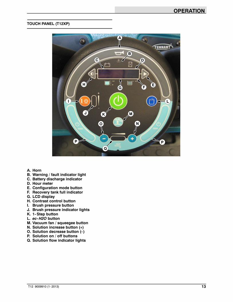
TOUCH PANEL (T12XP)
A
I
B
E
L
C
FGH
K M
NO
P
D
J
Q
P
A. HornB. Warning / fault indicator lightC. Battery discharge indicatorD. Hour meterE. Configuration mode buttonF. Recovery tank full indicatorG. LCD displayH. Contrast control buttonI. Brush pressure buttonJ. Brush pressure indicator lightsK. 1- Step buttonL. ec-H2O buttonM. Vacuum fan / squeegee buttonN. Solution increase button (+)O. Solution decrease button (- )P. Solution on / off buttonsQ. Solution flow indicator lights

OPERATION
14 T12 9009910 (1- 2013)
SYMBOL DEFINITIONS
These symbols are used on the machine toidentify controls, displays, and features.
Fault indicator Recovery tank
Vacuum fan / squeegee Operating lights
1- STEP Hazard light
ec-H2O (option) Scrub mode
Solution flow Circuit breaker
Increase Spray nozzle (option)
Decrease On
Main brush pressure Off
Side brush (option) Solution On / Off
Battery charge Emergency shut- off
Horn Contrast control
Hour meter Jack point
Solution tank Solution flow (maximum / minimum)
Forward / Reverse Brush pressure (maximum / minimum)

OPERATION
15T12 9009910 (11- 2019)
INSTALLING BATTERIES
FLOODED/SEALED LEAD-ACID BATTERIES
WARNING: Fire Or Explosion Hazard.Batteries Emit Hydrogen Gas. KeepSparks And Open Flame Away. KeepBattery Hood Open When Charging.
FOR SAFETY: When servicing machine, wearprotective gloves and eye protection whenhandling batteries and battery cables. Avoidcontact with battery acid. Battery installationmust be done by trained personnel.
BATTERY SPECIFICATIONS
Six 6- volt deep cycle lead acid batteries.
Maximum battery dimensions: 7 in / 177.8 mm Wx 11.8 in / 299.7 mm L x 15 in / 380 mm H.
1. Park the machine on a level surface andremove the key.
2. To engage the seat support, lift the seatcompletely open until the pin slides into thelower notch of the seat support.
Machines with deluxe seat option only: Pull andhold the Operator seat release handle forward tounlock the seat before lifting the seat open.
3. Carefully install the batteries into the batterycompartment tray and arrange the batteryposts as shown. Insert the foam spacersalong side the batteries as shown if installingthe smaller batteries.
NOTE: For large traction batteries, remove theseat assembly and use a hoist to install thebattery.
Front of machine
Foam
Spacer
Foam
Spacer
Foam
Spacer
Foam
Spacer
4. Using the supplied battery post boots,connect the cables to the battery posts,RED TO POSITIVE (+) & BLACK TONEGATIVE (- ).
IMPORTANT: Make sure that the charger isproperly set for the battery type beforecharging (See ON-BOARD CHARGERSETTINGS).

OPERATION
16 T12 9009910 (11- 2019)
LITHIUM- ION BATTERY
For machines equipped with lithium- ionbattery, contact Tennant Service for batteryservice and replacement.
FOR SAFETY: When using Lithium- ionBattery Model, battery service to be performedby Tennant personnel only. Batteryinstallation requires a specific service kitwhich includes a hoisting strap and properlifting instructions. Contact Tennant Service.
OPERATION OF CONTROLS
BATTERY DISCHARGE INDICATOR
The Battery discharge indicator displays thecharge level of the batteries while the machine isoperating.
T12 T12XP
When the batteries are fully charged, all five barsare lit. Recharge the batteries when there is onlyone bar shown in the display. Do not allow thebatteries to discharge below the last bar.
NOTE: The reading on the battery dischargeindicator is not accurate when the machine is firstpowered on. Operate the machine a few minutesbefore reading the charge level of the batteries.
NOTE: The flashing Warning / fault indicator andbattery low fault in the LCD (liquid crystal display)will not reset until after the batteries have beenfully charged. See FAULT INDICATOR(S).
NOTE: Lithium- ion Battery Model - Do not storethe machine for an extended period if battery isdischarged to the last bar, the battery may furtherdischarge to a level that is unrecoverable.
HOUR METER
The Hour meter records the hours the machinewas operated. Use this information to determinemachine service intervals.
T12 T12XP
RECOVERY TANK FULL INDICATOR
The Recovery tank full indicator displays 0%when the recovery tank is not yet full and 100%when the recovery tank is full. All scrubbingfunctions will stop when the recovery tank is full.Empty the recovery tank when the indicatordisplays 100%.
T12 T12XP

OPERATION
17T12 9009910 (1- 2013)
EMERGENCY SHUT-OFF BUTTON
The Emergency shut- off button immediatelystops all power to the machine.
Stop machine power: Push the Emergencyshut- off button.
Restart machine power: Turn the Emergencyshut- off button to the right to release the button.Turn the key switch to the Off position, then turnthe key fully clockwise and release it to the Onposition.
NOTE: Lithium- ion Battery Model - To restartmachine, turn key switch off and wait up to 3seconds for machine power to completely shut offthen turn key switch back on again.
Only use this button in the event of anemergency. It is not intended for routine machineshutdown.
OPERATING / HAZARD LIGHT SWITCH(OPTION)
Operating and Hazard Lights On: Press the top ofthe Operating / hazard light switch.
Hazard Lights On: Press the Operating / hazardlight switch to the middle position.
All Lights Off: Press the bottom of the Operating /hazard light switch.
T12
T12XP

OPERATION
18 T12 9009910 (1- 2013)
OPERATOR SEAT
The front- to- back adjustment lever adjusts theseat position.
SEAT BELTS (Deluxe Seat Option Only)
FOR SAFETY: Before starting machine, adjustseat and fasten seat belt.
SEAT SUPPORT
The Seat support holds the seat up to allowaccess to the batteries and circuit breakers.
To engage the seat support, lift the seatcompletely open until the pin slides into the lowernotch of the seat support.
Machines with deluxe seat option only: Pulland hold the Operator seat release handleforward to unlock the seat before lifting theseat open.
OPERATION
19T12 9009910 (5- 2017)
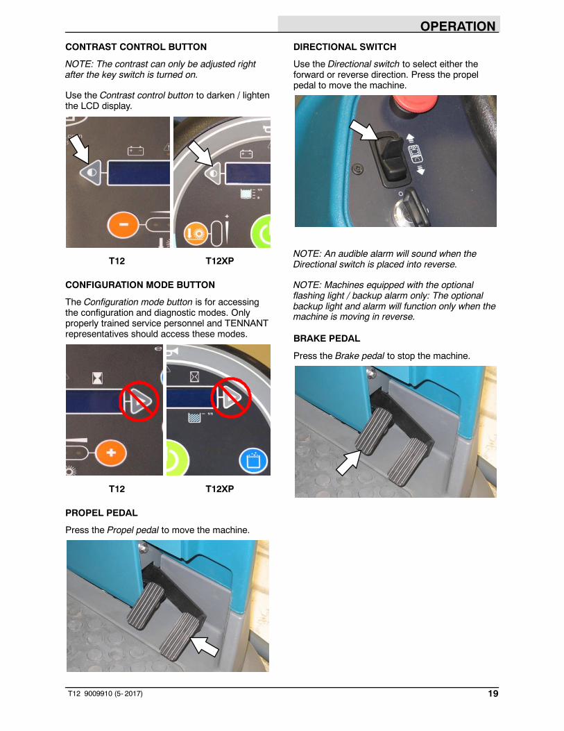
CONTRAST CONTROL BUTTON
NOTE: The contrast can only be adjusted rightafter the key switch is turned on.
Use the Contrast control button to darken / lightenthe LCD display.
T12 T12XP
CONFIGURATION MODE BUTTON
The Configuration mode button is for accessingthe configuration and diagnostic modes. Onlyproperly trained service personnel and TENNANTrepresentatives should access these modes.
T12 T12XP
PROPEL PEDAL
Press the Propel pedal to move the machine.
DIRECTIONAL SWITCH
Use the Directional switch to select either theforward or reverse direction. Press the propelpedal to move the machine.
NOTE: An audible alarm will sound when theDirectional switch is placed into reverse.
NOTE: Machines equipped with the optionalflashing light / backup alarm only: The optionalbackup light and alarm will function only when themachine is moving in reverse.
BRAKE PEDAL
Press the Brake pedal to stop the machine.
OPERATION
20 T12 9009910 (1- 2013)
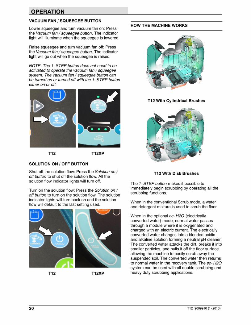
VACUUM FAN / SQUEEGEE BUTTON
Lower squeegee and turn vacuum fan on: Pressthe Vacuum fan / squeegee button. The indicatorlight will illuminate when the squeegee is lowered.
Raise squeegee and turn vacuum fan off: Pressthe Vacuum fan / squeegee button. The indicatorlight will go out when the squeegee is raised.
NOTE: The 1-STEP button does not need to beactivated to operate the vacuum fan / squeegeesystem. The vacuum fan / squeegee button canbe turned on or turned off with the 1- STEP buttoneither on or off.
T12 T12XP
SOLUTION ON / OFF BUTTON
Shut off the solution flow: Press the Solution on /off button to shut off the solution flow. All thesolution flow indicator lights will turn off.
Turn on the solution flow: Press the Solution on /off button to turn on the solution flow. The solutionindicator lights will turn back on and the solutionflow will default to the last setting used.
T12 T12XP
HOW THE MACHINE WORKS
T12 With Cylindrical Brushes
T12 With Disk Brushes
The 1- STEP button makes it possible toimmediately begin scrubbing by operating all thescrubbing functions.
When in the conventional Scrub mode, a waterand detergent mixture is used to scrub the floor.
When in the optional ec-H2O (electricallyconverted water) mode, normal water passesthrough a module where it is oxygenated andcharged with an electric current. The electricallyconverted water changes into a blended acidicand alkaline solution forming a neutral pH cleaner.The converted water attacks the dirt, breaks it intosmaller particles, and pulls it off the floor surfaceallowing the machine to easily scrub away thesuspended soil. The converted water then returnsto normal water in the recovery tank. The ec-H2Osystem can be used with all double scrubbing andheavy duty scrubbing applications.
OPERATION
21T12 9009910 (1- 2013)
BRUSH AND PAD INFORMATION
For best results, use the appropriate brush or padfor the cleaning application. Listed below arebrushes and pads and the applications for whicheach is best suited.
NOTE: The amount and type of soilage play animportant role in determining the type of brush orpad to use. Contact a Tennant representative forspecific recommendations.
Nylon brush (Disk)* - Softer nylon bristles arerecommended for scrubbing coated floors. Cleanswithout scuffing.
Polyester brush (Cylindrical) - Softer generalpurpose polyester bristles gently clean whilescrubbing. Perfect for sensitive floor surfaces.Polyester does not absorb water so it is preferredover Nylon in wet applications.
PolyPro brush (Cylindrical) - Heavy dutypolypropylene bristles provide a more aggressivecleaning performance and can more easily liftcompacted dirt, debris, and sand while offeringexcellent scrubbing performance.
Polypropylene brush (Cylindrical and Disk)* -General purpose polypropylene bristles lift lightlycompacted dirt without scuffing high-gloss coatedfloors.
Super AB brush (Cylindrical and Disk)* -Nylon fiber with an abrasive grit to remove stainsand compacted dirt. Aggressive action on anysurface. Performs well on buildup, grease, or tiremarks.
* This brush is also available for the side brush.
Stripping pad (Brown)- For stripping of floorfinish to prepare the floor for recoating.
Scrubbing pad (Blue) - For medium toheavy- duty scrubbing. Removes dirt, spills, andscuffs.
Buffing pad (Red) - For light duty scrubbingwithout removing floor finish.
Polishing pad (White) - For maintaining highlypolished or burnished floors.
High productivity stripping pad (Black) - Foraggressive stripping of heavy finishes or sealers,or for very heavy duty scrubbing. This pad canonly be used with the grip pad driver, not thetufted pad driver.
Surface preparation pad (Maroon) - For veryaggressive chemical free removal of floor finish toprepare the floor for re- coating
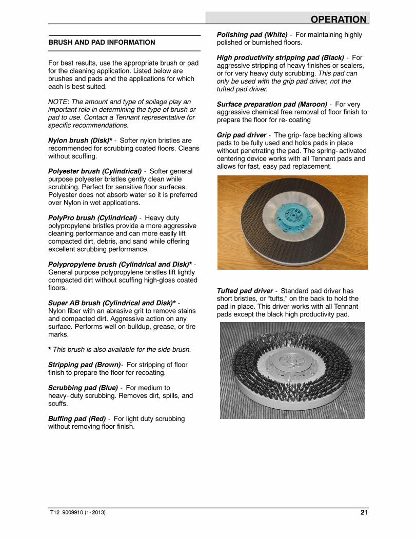
Grip pad driver - The grip- face backing allowspads to be fully used and holds pads in placewithout penetrating the pad. The spring- activatedcentering device works with all Tennant pads andallows for fast, easy pad replacement.
Tufted pad driver - Standard pad driver hasshort bristles, or “tufts,” on the back to hold thepad in place. This driver works with all Tennantpads except the black high productivity pad.

OPERATION
22 T12 9009910 (8- 2014)
WHILE OPERATING THE MACHINE
Pick up oversized debris before scrubbing. Pickup wire, string, twine, large pieces of wood, or anyother debris that could become wrapped aroundor tangled in the brushes.
Drive in a straight a path as possible. Avoidbumping into posts or scraping the sides of themachine. Overlap the scrub paths by severalcentimeters (a few inches).
Avoid turning the steering wheel too sharply whenthe machine is in motion. The machine is veryresponsive to the movement of the steering wheel.Avoid sudden turns, except in emergencies.
Adjust the machine speed, brush pressure, andsolution flow as required when scrubbing. Use thelowest brush pressure and solution flow settingsfor best performance.
If poor cleaning performance is observed, stopcleaning and refer to MACHINETROUBLESHOOTING in this manual.
Perform the Daily Maintenance Procedures aftereach use (see MACHINE MAINTENANCE in thismanual).
Drive the machine slowly on inclines. Use thebrake pedal to control machine speed ondescending inclines. Scrub with the machine upinclines rather than down inclines.
FOR SAFETY: When using machine, go slowlyon inclines and slippery surfaces.
Do not operate machine in areas where theambient temperature is above 43_ C (110_ F). Donot operate scrubbing functions in areas wherethe ambient temperature is below freezing 0_ C(32_ F).
PRE-OPERATION CHECKLIST
Perform the following steps before operating themachine:
- Check the machine for fluid leaks.
- Check the operating lights.
- Check left side squeegee for wear anddamage.
- Check main brushes for wear and damage.Remove wire, string, or twine wrapped aroundthe main scrub brushes.
- Machines equipped with cylindrical brushes:Confirm the debris tray is empty and clean.
- Machines equipped with side brush option:Check for wire, string, or twine wrappedaround the scrub brush.
- Machines equipped with side brush option:Check squeegee for wear and damage.
- Check the rear squeegees for wear anddamage.
- Check the recovery tank cover seals for wearor damage.
- Confirm the vacuum fan inlet filter is clean.
- Check the right side squeegee for wear anddamage.
- ec-H2O Scrubbing: Confirm all conventionalcleaning agents/restorers are drained andrinsed from the solution tank.
- ec-H2O Scrubbing: Confirm the solution tankis filled with clear cool water only.
- Check the horn, headlights, taillights, safetylights, and backup alarm (if equipped).
- Check the brakes and steering for properoperation.
- Check the tires for damage.
- Check maintenance records to determinemaintenance requirements.

OPERATION
23T12 9009910 (11- 2019)
STARTING THE MACHINE
FOR SAFETY: Before starting machine, adjustseat and fasten seat belt (if equipped).
1. Sit in the operators seat.
2. Turn the Key switch completely past the Onposition and release the key switch. The keyswitch will automatically return to the Onposition.
NOTE: Lithium- ion Battery Model - It is notrequired to turn the key switch completely pastthe On position to start machine. However, thereis a slight delay before the machine power turnson after turning key switch. There is also a 3second delay when powering off the machine.
NOTE: Lithium- ion Battery Model - The machinewill automatically shut off if not operated for morethan one hour to conserve battery energy. Torestart machine, turn key switch off and wait up to3 seconds before turning key switch back again.
3. Turn on lights (if equipped).
4. Place the Directional switch into the directionneeded to travel.
5. Press the Propel pedal to move the machine.
NOTE: The machine will not travel unless theoperator is sitting in the operator seat.
FILLING THE SOLUTION TANK
ec-H2O SCRUBBING (ec-H2O MODE)
FOR SAFETY: Before leaving or servicingmachine, stop on level surface, turn offmachine, and remove key.
1. Remove the cap from the solution tank.
2. Fill the solution tank with only clean COOLWATER (less than 21C / 70F). DO NOT usehot water or add any conventional floorcleaning detergents or an ec-H2O systemfailure may result. Fill the solution tank withwater until the level is approximately 50 mm(2 in) below the cap.
WARNING: Flammable materials cancause an explosion or fire. Do not useflammable materials in tank(s).
NOTE: Do not use the ec-H2O system whenthere are conventional cleaning detergents in thesolution tank. Drain, rinse, and refill the solutiontank with clear cool water before operating theec-H2O system. Conventional cleaningdetergents may cause an ec-H2O system failure.
3. Reinstall the cap onto the solution tank.

OPERATION
24 T12 9009910 (1- 2013)
CONVENTIONAL SCRUBBING MODE
FOR SAFETY: Before leaving or servicingmachine, stop on level surface, turn offmachine, and remove key.
1. Open the solution tank cover.
2. Partially fill solution tank with water (not toexceed 60C / 140F). Pour the requiredamount of detergent into the solution tank.Continue filling the solution tank with wateruntil the level is approximately 50 mm (2 in)below the cap.
WARNING: Flammable materials cancause an explosion or fire. Do not useflammable materials in tank(s).
ATTENTION: For Conventional Scrubbing,only use recommended cleaning detergents.Machine damage due to improper detergentusage will void the manufacturer warranty.
NOTE: Pour a recommended foam controlsolution into the recovery tank if excessive foamappears. For specific detergentrecommendations, contact a Tennantrepresentative.
3. Close the solution tank cover.
ec-H2O BUTTON (OPTION)
The ec-H2O button enables the ec-H2O systemto come on when the 1- STEP button is activated.The light between the ec-H2O logo and ec-H2Obutton will come on. The machine will default tothe last setting used when it is powered on or off.
T12 T12XP

OPERATION
25T12 9009910 (1- 2013)
SETTING BRUSH PRESSURE
Under normal cleaning conditions, the brushpressure should be set to the lowest setting.Under heavy grime conditions, the brush pressurecan be set to a higher setting. Travel speed andfloor conditions will affect cleaning performance.If brushes are worn, it may be necessary toincrease the brush pressure. The machine willdefault to the last setting used when it is poweredon or off.
T12 Only: With the 1- STEP button activated,press either the Brush pressure increase button(+) or Brush pressure decrease button (- ) to setthe brush pressure.
T12
T12XP Only: With the 1- STEP button activated,press the Brush pressure button to both raise orlower the brush pressure settings.
T12XP
SETTING SOLUTION FLOW
With the 1- STEP button activated, press eitherSolution increase button (+) or Solution decreasebutton (- ) to set the solution flow level. Travelspeed and floor conditions will affect scrubbingperformance. Under normal soilage conditions thesolution flow level should be set to the lowestsetting (the left light). Under heavy grimeconditions, the solution flow level should be set tothe higher settings (middle or right lights). Themachine will default to the last setting used whenthe machine is powered on or off. The solutionflow indicator lights display the current solutionflow setting.
T12
T12XP
OPERATION
26 T12 9009910 (NIL)
SCRUBBING
FOR SAFETY: Do not operate machine, unlessoperator manual is read and understood.
1. Turn on the machine.
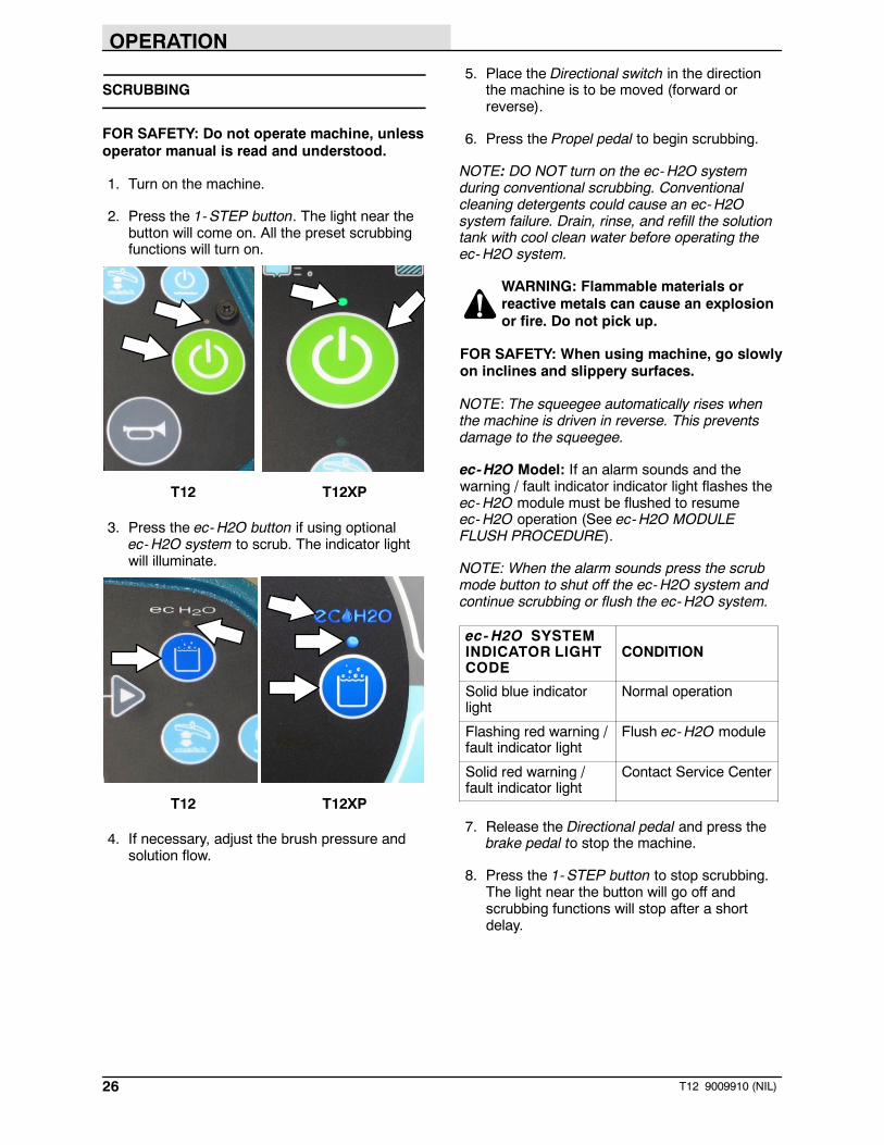
2. Press the 1- STEP button. The light near thebutton will come on. All the preset scrubbingfunctions will turn on.
T12 T12XP
3. Press the ec-H2O button if using optionalec-H2O system to scrub. The indicator lightwill illuminate.
T12 T12XP
4. If necessary, adjust the brush pressure andsolution flow.
5. Place the Directional switch in the directionthe machine is to be moved (forward orreverse).
6. Press the Propel pedal to begin scrubbing.
NOTE: DO NOT turn on the ec-H2O systemduring conventional scrubbing. Conventionalcleaning detergents could cause an ec-H2Osystem failure. Drain, rinse, and refill the solutiontank with cool clean water before operating theec-H2O system.
WARNING: Flammable materials orreactive metals can cause an explosionor fire. Do not pick up.
FOR SAFETY: When using machine, go slowlyon inclines and slippery surfaces.
NOTE: The squeegee automatically rises whenthe machine is driven in reverse. This preventsdamage to the squeegee.
ec-H2O Model: If an alarm sounds and thewarning / fault indicator indicator light flashes theec-H2O module must be flushed to resumeec-H2O operation (See ec-H2O MODULEFLUSH PROCEDURE).
NOTE: When the alarm sounds press the scrubmode button to shut off the ec-H2O system andcontinue scrubbing or flush the ec-H2O system.
ec- H2O SYSTEMINDICATOR LIGHTCODE
CONDITION
Solid blue indicatorlight
Normal operation
Flashing red warning /fault indicator light
Flush ec-H2O module
Solid red warning /fault indicator light
Contact Service Center
7. Release the Directional pedal and press thebrake pedal to stop the machine.
8. Press the 1- STEP button to stop scrubbing.The light near the button will go off andscrubbing functions will stop after a shortdelay.

OPERATION
27T12 9009910 (1- 2013)
DOUBLE SCRUBBING
Use the double scrubbing method to clean heavilysoiled areas.
Double scrubbing can be performed using theec-H2O SCRUBBING SYSTEM (option) orCONVENTIONAL SCRUBBING methods.
To raise the side squeegees for double scrubbing,remove the clevis pins from the storage locations.Manually raise both side squeegee assemblies,then reinsert the pins into the holes in the sidesqueegee brackets.
Press the 1- STEP button and then the Vacuumfan/squeegee button. The light above the Vacuumfan/squeegee button will turn off, the squeegeewill rise, and the vacuum fan will stop operating.Scrub the heavily soiled area. Let the cleaningsolution soak on the floor for 5- 15 minutes.
T12 T12XP
FOR SAFETY: When using machine, go slowlyon inclines and slippery surfaces.
Before scrubbing the floor a second time, lowerthe side squeegees and press the Vacuumfan/squeegee button to lower the rear squeegeeand turn on the vacuum fan. The light above thebutton will come on. Scrub the floor a second timeto pick up the cleaning solution.
WARNING: Flammable materials orreactive metals can cause an explosionor fire. Do not pick up.
NOTE: To turn off the solution flow whenscrubbing the area a second time, press theSolution on / off button Press the Solution on / offbutton again to restart the solution flow.
T12 T12XP
NOTE: Double scrubbing is not recommended inareas where the cleaning solution will run underracks or damage products.

OPERATION
28 T12 9009910 (1- 2013)
WATER PICKUP MODE (NO SCRUBBING)
The machine can be used to pick up water ornon- flammable liquid spills without scrubbing.
To pick up water or non- flammable liquid spills,make sure the 1- STEP button is not activated.The light above the button must be off.
T12 T12XP
WARNING: Flammable materials orreactive metals can cause an explosionor fire. Do not pick up.
Press the Vacuum fan/squeegee button. The lightabove the button will come on, the squeegee willlower, and the vacuum fan will start operating.Pick up the water or non- flammable liquid spill.
T12 T12XP
STOP SCRUBBING
1. While the machine is still in motion, press the1- Step button to stop the scrubbingoperations. The squeegee will briefly remainlowered to the floor to pick up the water in thescrub head, and then raises.
T12 T12XP
2. Release the Propel pedal and press the Brakepedal to stop the machine.
OPERATION
29T12 9009910 (1- 2013)
DRAINING AND CLEANING THE RECOVERYTANK
Drain and clean the recovery tank daily or whenthe recovery tank full fault code appears on theLCD display.
Clean the outside of the tank with vinyl cleaner.
1. Drive the machine near a floor drain.
FOR SAFETY: Before leaving or servicingmachine, stop on level surface, turn offmachine, and remove key.
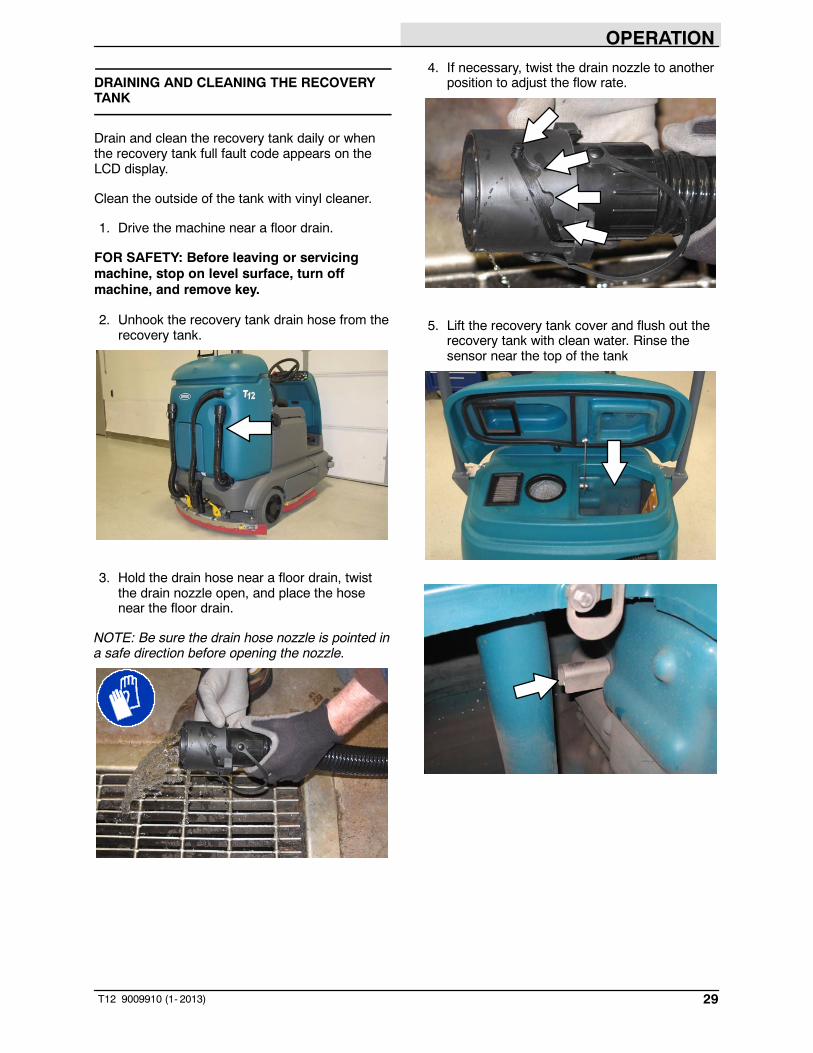
2. Unhook the recovery tank drain hose from therecovery tank.
3. Hold the drain hose near a floor drain, twistthe drain nozzle open, and place the hosenear the floor drain.
NOTE: Be sure the drain hose nozzle is pointed ina safe direction before opening the nozzle.
4. If necessary, twist the drain nozzle to anotherposition to adjust the flow rate.
5. Lift the recovery tank cover and flush out therecovery tank with clean water. Rinse thesensor near the top of the tank

OPERATION
30 T12 9009910 (1- 2013)
6. To prevent leaks, clean the plug portion of thenozzle and the interior of the drain hose cuff.
NOTE: DO NOT use steam to clean the tanks.Excessive heat can damage the tanks andcomponents.
7. Twist the drain cuff closed and insert the drainhose back into the clip on the recovery tank.
8. Check the vacuum fan inlet filter daily. Cleaninlet filter with a damp cloth or hose whendirty. Allow filter to completely dry beforereinstalling it into the machine.
9. Remove the vacuum screen from therecovery tank and rinse the screen.
10. Remove the debris tray from the recoverytank and rinse all debris from the tray.
11. Close the recovery tank cover.
12. Cylindrical scrub head: Remove and clean thedebris trough. Place the trough back in thescrub head when clean.
NOTE: The scrub head must be loweredapproximately 25 mm (1 in) to remove debristrough.
NOTE: The debris trough can be removed fromthe right side of the machine only.

OPERATION
31T12 9009910 (1- 2013)
DRAINING AND CLEANING THE SOLUTIONTANK
Clean the outside of the tank with vinyl cleaner.
1. Drive the machine near a floor drain.
FOR SAFETY: Before leaving or servicingmachine, stop on level surface, turn offmachine, and remove key.
2. Remove the solution tank drain hose from thesolution tank.
3. Hold the drain hose near a floor drain, twistthe drain nozzle open, and place the hosenear the floor drain.
NOTE: Be sure the drain hose nozzle is pointed ina safe direction before opening the nozzle.
4. If necessary, twist the drain nozzle to anotherposition to adjust the flow rate.
5. Remove the cap from the solution tank andflush out the solution tank with clean water.
NOTE: DO NOT use steam to clean the tanks.Excessive heat can damage the tanks andcomponents.
6. To prevent leaks, clean the plug portion of thenozzle and the interior of the drain hose cuff.

OPERATION
32 T12 9009910 (5- 2015)
7. Twist the drain cuff closed and insert the drainhose back into the clip on the recovery tank.
8. If the solution tank filter gets clogged, removethe drain hose to access and clean the filter.
TURN OFF THE MACHINE
1. Remove foot from the Propel pedal.
2. Press the 1- Step button to stop scrubbing.
3. Press the Brake pedal to stop the machine.
4. Turn the Key switch to the Off position.

OPERATION
33T12 9009910 (11- 2019)
FAULT INDICATOR(S)
This machine is equipped with two visualindicators, a red indicator light and an LCD (liquidcrystal display).
The red indicator light will blink continuouslyindicating that a fault has occurred.
The LCD will display a fault code. If there is morethan one fault, each fault code will alternatelydisplay.
All faults codes are also accompanied by anaudible alarm to alert the operator a fault hasoccurred.
To reset the fault indicators, turn the machine off,then eliminate the cause of the fault. The faultindicator will reset when the machine is restarted.
NOTE: Lithium- ion Battery Model - To clear faultcode, turn the key switch off and wait up to 3seconds for machine power to completely shutoff. Then turn key switch back on again.
Refer to the table below to determine the causeand remedy for the fault.
T12
T12XP
Fault Code(Displayed in LCD)
Cause(s) Remedy
F1:Rcv Tank Full Recovery tank is full Empty recovery tankF2: Sol Tank Empty Solution tank is empty Fill solution tank.F3: Vac # Flt # Vacuum fan motor(s) not
operatingShut off and restart machine.If fault code still appears, stop using machineand contact Tennant service representative.
F4: Batt Very Low Low battery charge Recharge batteryF5: Propel Error Propel controller error Turn off and restart machine.
If fault code still appears, stop using machineand contact Tennant service representative.
F6: Left Br Flt # Left brush not operating
F6: Frnt Br Flt# Front brush not operating
F7: Rght Br Flt# Right brush not operating
F7: Rear Br Flt# Rear brush not operating
F8: Hi B3 Current Side brush not operating
F9: Pickup Error Vacuum not operating
F10: Scrub Error Scrub head not operating
F12: Check Brushes Brushes not operating
F14: ec- H2O Error ec-H2O system not operating

OPERATION
34 T12 9009910 (1- 2013)
WARNING CODES
Warning codes are typically caused by theoperator attempting to activate modes that are notavailable. The warning code will appear in theLCD (liquid crystal display).
T12
T12XP
Refer to the table below to determine the cause ofthe warning code.
Warning Code(Displayed in LCD)
Cause(s) Remedy
W1: Batt. Low Low battery charge Charge batteriesW2: Sqge Stall Rear squeegee not lowering Check squeegee / squeegee actuator for
obstructions or damageW3: Side Stall Side brush not lowering Check side brush actuator for obstructionsW4: Unavailable Optional solution not enabled Solution mode not availableW5: No Side Brush Side brush not enabled Side brush not availableW6: Ec Offline ec-H2O system not operating Turn off and restart machine.
If warning code still appears, stop usingmachine and contact Tennant servicerepresentative.
W7: Not Active Button inactive Button not active for useW8: No Vac. Amps Vacuum fan not operating Check harness connection. Reconnect
harness if it is unconnected.If warning code still appears, stop usingmachine and contact a Tennant servicerepresentative.
W9: Open R/R Brush Right / rear brush not operatingW10: Open L/F Brush Left / front brush not operatingW11: Open SD Brush Side brush not operatingW12: Solution Off No solution flow to scrub head Press Solution on / off button to start solution
flow.W13: Side Offline Side brush not operating Turn off and restart machine.
If warning code still appears, stop usingmachine and contact Tennant servicerepresentative.

OPERATION
35T12 9009910 (1- 2013)
OPTIONS
SPRAY NOZZLE (OPTION)
The spray nozzle is used to clean the machineand surrounding areas. The solution tank providesa water/solution supply for the spray nozzle.
FOR SAFETY: When servicing machine, donot power spray or hose off machine nearelectrical components.
FOR SAFETY: Before leaving or servicingmachine and stop on level surface.
1. Turn on the machine.
2. Press the top of the Spray nozzle switch toturn on the spray nozzle. The light on theswitch will come on when the spray nozzle isturned on.
T12
T12XP
3. Pull the spray nozzle out from the back of themachine and clean as needed.
4. When finished cleaning, gently pull the hoseand allow the spray nozzle hose to retractback into the machine.
NOTE: Continue holding onto the spray nozzleand control the hose while it is retracting back intothe machine. The machine and / or the spraynozzle assembly could be damaged if the spraynozzle hose is released and allowed to rapidlyretract into the machine.
5. Place the spray nozzle onto the hook.
6. Press the bottom of the Spray nozzle switchto turn off the water supply. The light on theswitch will turn off when the spray nozzle isturned off.
NOTE: Be sure the Spray nozzle switch is turnedoff before continuing scrubbing. The spray nozzlepump could be damaged if the switch is left onwhile scrubbing.

OPERATION
36 T12 9009910 (1- 2013)
VACUUM WAND (OPTION)
Use the vacuum wand to clean areas that are outof reach of the machine.
WARNING: Flammable materials orreactive metals can cause an explosionor fire. Do not pick up.
1. Unsnap the vacuum wand lanyard from thesolution tank.
2. Remove the vacuum wand / squeegeevacuum hose from the rear squeegee.
3. Insert the vacuum wand cap into the vacuumport in the vacuum wand.
4. Twist the vacuum nozzle to the vacuumposition and extend the handle to the desiredlength.
5. Turn on the machine.
6. Press the Vacuum fan/squeegee button toturn on the vacuum fan. The squeegee willcompletely lower.
T12 T12XP
7. Vacuum the floor.
OPERATION
37T12 9009910 (1- 2013)
8. When finished vacuuming, press the Vacuumfan/squeegee button to turn off the vacuumfan. The squeegee will raise.
9. Turn off the machine.
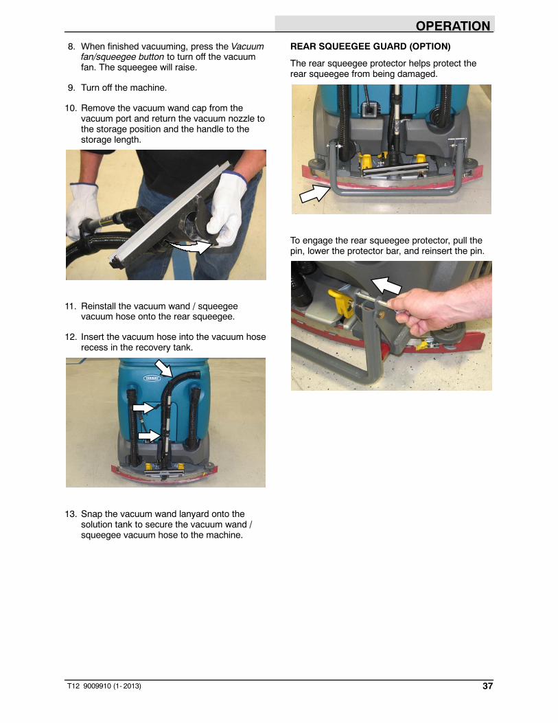
10. Remove the vacuum wand cap from thevacuum port and return the vacuum nozzle tothe storage position and the handle to thestorage length.
11. Reinstall the vacuum wand / squeegeevacuum hose onto the rear squeegee.
12. Insert the vacuum hose into the vacuum hoserecess in the recovery tank.
13. Snap the vacuum wand lanyard onto thesolution tank to secure the vacuum wand /squeegee vacuum hose to the machine.
REAR SQUEEGEE GUARD (OPTION)
The rear squeegee protector helps protect therear squeegee from being damaged.
To engage the rear squeegee protector, pull thepin, lower the protector bar, and reinsert the pin.

OPERATION
38 T12 9009910 (11- 2015)
SIDE BRUSH (OPTION)
The side brush moves debris into the path of themain brushes.
WARNING: Flammable materials orreactive metals can cause an explosionor fire. Do not pick up.
1. Turn on the machine
2. Press the top of the Side brush switch toenable the side brush assembly.
T12
T12XP
3. Press the 1- Step button. The side brushassembly will lower with the main brush.
NOTE: The 1- Step button controls the side brushassembly when the Side brush switch is in the On(top) position.
4. Press the Propel pedal to begin scrubbing.
5. Press the bottom of the Side brush switch tostop and raise the side brush.
ADJUSTING BACKUP ALARM VOLUME(OPTION)
FOR SAFETY: When using machine, followsite safety guidelines concerning backupalarms.
The backup alarm volume can be adjusted from85- 102 dB(A). To adjust the volume, remove thebackup alarm cover and turn the volume knob.
Increase volume: Turn the knob clockwise.
Decrease volume: Turn the knobcounter- clockwise.

OPERATION
39T12 9009910 (1- 2013)

OPERATION
40 T12 9009910 (5- 2015)
MACHINE TROUBLESHOOTING
Problem Cause RemedyMachine will not operate Emergency stop button activated Turn button clockwise to reset
Machine fault detected See FAULT INDICATORS orWARNING CODES
Discharged batteries Charge batteriesLoose battery cable(s) Tighten loose cable(s)Faulty battery(s) Replace battery(s)Faulty key switch Contact Tennant service
representativeFaulty control board Contact Tennant service
representativeOn- board battery chargerwill not operate
Plug not connected to powersupply
Check plug connection
Faulty charger fuse Replace charger fuseFaulty power supply chord Replace power supply chordError detected See ON- BOARD BATTERY
CHARGER ERROR CODESTrailing water - poor or nowater pickup
Worn squeegee blades Rotate or replace squeegee bladesSqueegee out of adjustment Adjust squeegeeClogged squeegee assembly Clean squeegee assemblyVacuum hose loose Secure vacuum hose connectionsVacuum hose clogged Flush vacuum hoseVacuum hose damaged Replace vacuum hoseVacuum fan inlet filter dirty Clean inlet filterDebris caught on squeegee Remove debris from squeegeeVacuum hose to squeegee orrecovery tank disconnected ordamaged
Reconnect or replace vacuum hose
Tank cover not completely closed Check for obstructionsTorn seals on recovery tank Replace seals
Vacuum fan will not turn on Recovery tank full Drain recovery tankFoam filling recovery tank Empty recovery tank
Use less or change detergentUse a defoamer
Little or no solution flow tothe floor
Solution tank empty Fill solution tankSolution flow turned off Turn solution flow onSolution supply lines plugged Flush solution supply linesSolution solenoid clogged or stuck Clean or replaceSolution tank filter clogged Clean filter
OPERATION
41T12 9009910 (1- 2013)
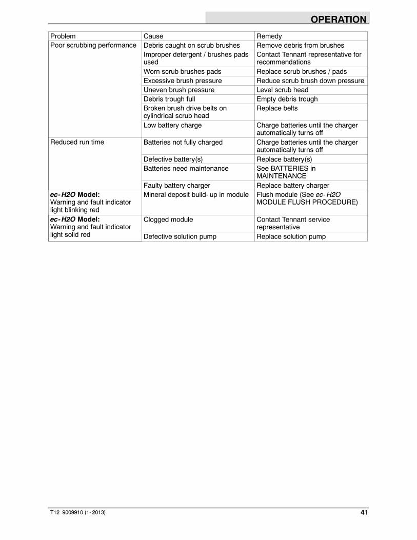
Problem Cause RemedyPoor scrubbing performance Debris caught on scrub brushes Remove debris from brushes
Improper detergent / brushes padsused
Contact Tennant representative forrecommendations
Worn scrub brushes pads Replace scrub brushes / padsExcessive brush pressure Reduce scrub brush down pressureUneven brush pressure Level scrub headDebris trough full Empty debris troughBroken brush drive belts oncylindrical scrub head
Replace belts
Low battery charge Charge batteries until the chargerautomatically turns off
Reduced run time Batteries not fully charged Charge batteries until the chargerautomatically turns off
Defective battery(s) Replace battery(s)Batteries need maintenance See BATTERIES in
MAINTENANCEFaulty battery charger Replace battery charger
ec-H2O Model:Warning and fault indicatorlight blinking red
Mineral deposit build- up in module Flush module (See ec-H2OMODULE FLUSH PROCEDURE)
ec-H2O Model:Warning and fault indicatorlight solid red
Clogged module Contact Tennant servicerepresentative
Defective solution pump Replace solution pump

MAINTENANCE
42 T12 9009910 (11- 2019)
MAINTENANCE
1
2
3
4
5
6
7
89
10
11 12
1
8
13
13 13
356389 356290
MAINTENANCE CHART
The table below indicates the Person Responsible for each procedure.O = Operator.T = Trained Personnel.
IntervalPersonResp. Key Description Procedure
Lubricant/Fluid
No. ofServicePoints
Daily O 1 Side and rear squeegees Check for damage andwear
- 4
O 2 Main brushes Check for damage, wear,and debris
- 2
O 3 Recovery tank Clean tank and checkcover seal
- 1
O 4 Vacuum fan inlet filter Clean - 1O 5 Cylindrical brushes only:
Debris trayClean - 1
O 12 Side brush (Option) Check for damage, wear,debris
- 1
O 12 Side brush squeegee(Option)
Check for damage andwear
- 1

MAINTENANCE
43T12 9009910 (7- 2013)
IntervalPersonResp. Key Description Procedure
Lubricant/Fluid
No. ofServicePoints
Weekly T 7 Battery cells Check electrolyte level DW 12
50Hours
T 6 Squeegee caster wheelpivot points
Lubricate SPL 2
T 1 Side and rear squeegees Check deflection andleveling
- 4
O 2 Main brushes (cylindrical) Rotate brushes from frontto rear
- 2
T 13 Scrub head skirts (disk) Check skirts for damageand wear
- 2
100Hours
T 7 Battery watering system(option)
Check hoses andconnections for damageand wear
- Multiple
200Hours
T 7 Battery terminals andcables
Check and clean - 12
T 8 Cylindrical brush drivebelts
Check for damage andwear
- 2
T 13 Steering chain(T12XP Only)
Lubricate, check tension,and check for damage andwear.
GL 1
T 9 Steering gear chain Lubricate, check tension,and check for damage andwear.
GL 1
500Hours
T 10 Vacuum fan motor(s) Check motor brushes - 1 (2)O 11 Tires Check for damage and
wear- 3
1000Hours
T 8 Main brush motors Check motor brushes(Check every 100 hoursafter initial 1000 hourcheck)
- 2 (4)
T 12 Side brush motor Check motor brushes(Check every 100 hoursafter initial 1000 hourcheck)
- 1
LUBRICANT/FLUID
DW Distilled water.. . . .SPL Special lubricant, Lubriplate EMB grease (Tennant part number 01433- 1). . .GL SAE 90 weight gear lubricant. . . .
NOTE: More frequent maintenance intervals may be required in extremely dusty conditions.

MAINTENANCE
44 T12 9009910 (11- 2015)
YELLOW TOUCH POINTS
This machine features easy to find yellow touchpoints for simple service items. No tools arerequired to perform these maintenanceoperations.
LUBRICATION
FOR SAFETY: Before leaving or servicingmachine, stop on level surface, turn offmachine, and remove key.
STEERING CHAIN (T12XP ONLY)
The steering chain is located on the steeringcolumn directly under the control panel. Check fordamage or wear and lubricate the steering chainafter every 200 hours.
STEERING GEAR CHAIN
The steering gear chain is located directly abovethe front tire. Check for damage or wear andlubricate the steering gear chain after every 200hours.
REAR SQUEEGEE CASTERS
Lubricate the rear squeegee caster pivot point oneach squeegee caster after every 50 hours.

MAINTENANCE
45T12 9009910 (11- 2019)
BATTERIES
FOR SAFETY: Before leaving or servicingmachine, stop on level surface, turn offmachine, set parking brake (if equipped), andremove key.
The lifetime of the batteries depends on theirproper maintenance. To get the most life from thebatteries;
FLOODED (WET) AND MAINTENANCE-FREESEALED LEAD-ACID BATTERIES
- Do not charge the batteries more than once aday and only after running the machine for aminimum of 15 minutes.
- Do not leave the batteries partially dischargedfor long period of time.
- Only charge the batteries in a well-ventilatedarea to prevent gas build up. Charge batteriesin areas with ambient temperatures 27_C(80_F) or less.
- Allow the charger to complete charging thebatteries before re-using the machine.
- Maintain the proper electrolyte levels offlooded (wet) batteries by checking levelsweekly.
CHECKING THE ELECTROLYTE LEVEL
The flooded (wet) lead- acid batteries requireroutine maintenance as described below. Checkthe battery electrolyte level weekly.
NOTE: Do Not check the electrolyte level if themachine is equipped with the battery wateringsystem. Proceed to the BATTERY WATERINGSYSTEM (OPTION).
08247
FOR SAFETY: When servicing machine, keepall metal objects off batteries. Avoid contactwith battery acid.
The level should be slightly above the batteryplates as shown before charging. Add distilledwater if low. DO NOT OVERFILL. The electrolytewill expand and may overflow when charging.After charging, distilled water can be added up toabout 3 mm (0.12 in) below the sight tubes.
Before Charging After Charging
NOTE: Make sure the battery caps are in placewhile charging. There may be a sulfur smell aftercharging batteries. This is normal.
MAINTENANCE-FREE BATTERIES
Maintenance- free batteries do not requirewatering. Cleaning and other routine maintenanceis still required.
CHECKING CONNECTIONS / CLEANING
After every 200 hours of use check for loosebattery connections and clean the surface of thebatteries, including terminals and cable clamps,with a strong solution of baking soda and water.Replace any worn or damaged wires. Do notremove battery caps when cleaning batteries.

MAINTENANCE
46 T12 9009910 (11- 2019)
LITHIUM- ION BATTERY PACK
The lithium- ion battery pack is amaintenance- free battery protected by a batterymanagement system (BMS). To achieve themaximum battery life, carefully follow theinstructions below:
- Carefully follow the Important SafetyInstructions section in the manual when usingthe Lithium- ion Battery Model.
- Only use the lithium- ion battery chargersupplied with machine.
- Charge battery pack in well- ventilated areas.For best charging performance, charge thebattery pack in temperatures below80_F/27_C and above 32_F/0_C. Batterypack may shut down and not take a charge inelevated or freezing temperatures.
- It is recommended to only recharge batterypack when discharge indicator level reachesthe last bar. Do not store the machine for anextended period if battery is discharged to thelast bar, the battery may further discharge toa level that is unrecoverable.
- When the machine shuts down due to adepleted battery pack, do not repeatedly cyclethe key switch on and off. This may causepermanent battery pack damage. Rechargebattery pack immediately to avoid damage.
- Allow charge cycle to completely chargebattery pack.
- Opportunity charging (i.e. partial charge cycleof a half hour or more) is only recommendedif discharge level is below 80%.
- Do not operate machine in temperaturesabove 110_F / 43_C or below - 4_F / - 20_C.Machine may shutdown if exceed thesetemperatures.
- When removing or replacing the lithium- ionbattery pack, a specific lifting kit isrecommended. It’s important to usenon- conductive lifting straps positioned at allfour lift points with straps angled at 45_ orgreater when hoisting battery pack.
- Contact Tennant Service for lithium- ionbattery service and replacement.
CHARGING THE BATTERIES(OFF-BOARD CHARGER)
IMPORTANT: Before charging, make sure thatthe charger setting is properly set for thebattery type.
1. Drive the machine to a flat, dry surface in awell- ventilated area.
2. Stop the machine and turn off the machinepower.
FOR SAFETY: Before leaving or servicingmachine, stop on level surface, turn offmachine, and remove key.
3. Lift the operator seat open and engage theseat support.
NOTE: Make sure the batteries have the properelectrolyte level before charging. See CHECKINGTHE ELECTROLYTE LEVEL.
4. Plug the charger AC power supply cord into aproperly grounded outlet.
5. Plug the charger connector into the remotebattery charge connector.
WARNING: Batteries emit hydrogen gas.Explosion or fire can result. Keepsparks and open flame away. Keepcovers open when charging.
NOTE: If the charger “FAULT CODE” lights flashwhen the batteries are plugged into the charger,refer to the charger manufacturer manual for faultcode definitions.
6. The Tennant charger will start automatically.When the batteries are fully charged, theTennant charger will automatically turn off.
7. After the charger has turned off, unplug thecharger connector from the remote batterycharge connector.

MAINTENANCE
47T12 9009910 (11- 2019)
ATTENTION: Do not disconnect the chargerDC cord from the machine receptacle whenthe charger is operating. Arcing may result. Ifthe charger must be interrupted duringcharging, disconnect the AC power supplycord first.
8. Close the operator seat.
CHARGING THE BATTERIES(ON-BOARD CHARGER)
IMPORTANT: Before charging, make sure thatthe charger setting is properly set for thebattery type. See ON-BOARD CHARGERSETTINGS.
1. Drive the machine to a flat, dry surface in awell- ventilated area.
2. Stop the machine and turn off the machinepower.
FOR SAFETY: Before leaving or servicingmachine, stop on level surface, turn offmachine, and remove key.
3. Lift the operator seat open and engage theseat support.
NOTE: Make sure the batteries have the properelectrolyte level before charging. See CHECKINGTHE ELECTROLYTE LEVEL.
4. Plug the on- board battery charger cord into aproperly grounded wall outlet.
WARNING: Batteries emit hydrogen gas.Explosion or fire can result. Keepsparks and open flame away. Keepcovers open when charging.
NOTE: The machine will not operate whencharging.
5. The on- board charger will start charging thebatteries. Once the charging cycle begins, theindicator lights will progress from red, yellowto green. When the green indicator light stayson, the charging cycle is done.
If the charger detects a problem, the charger willdisplay an error code (See ON-BOARDBATTERY CHARGER ERROR CODES).
6. Unplug the on- board battery charger from thewall outlet and neatly stow the cord inside thebattery compartment.
7. Close the operator seat.

MAINTENANCE
48 T12 9009910 (1- 2013)
ON-BOARD BATTERY CHARGER ERRORCODES
Display Code Fault Solutionbat Loose or damaged battery cable. Check battery cable connection.
Battery exceeded maximum voltage level. No action necessary.E01 Exceeded maximum battery voltage
allowed. Interrupts charging cycle.No action necessary.
E02 Safety thermostat exceeded maximuminternal temperature. Interrupts chargingcycle.
Ensure the charger vents are notobstructed. Clear obstructions.
E03 Exceeded maximum time for chargingphase, leaving the batteries underchargeddue to a sulfated or faulty battery. Interruptscharging cycle.
Repeat the charging cycle. If the errorcode E03 reappears check battery orreplace it.
SCt Safety timer exceeded maximum chargingtime. Interrupts charging cycle.
Replace battery.
Srt Possible internal short circuit. Contact a Tennant servicerepresentative.

MAINTENANCE
49T12 9009910 (11- 2019)
ON-BOARD CHARGER SETTINGS
NOTE: The following instructions are intended forflooded (wet) and maintenance- free lead- acidbatteries.
If the machine is equipped with the on- boardcharger, the charger settings are properly set atthe factory. If different batteries are put in themachine, the settings must be changed to matchthe new battery type before charging. Failure toproperly set the charger will result in batterydamage.
Refer to the battery label for the battery type.Contact the battery manufacturer if battery is notlabeled.
To verify the setting of the charger, connect thecharger cord into an electrical outlet. The chargerwill display a sequence of the following codes(three- digits + the code) when the cord isconnected:
A = Charging currentU = Battery Voltageh = Charging timeC = Charging ampere- hours [Ah]E = Energy used [Kwh]“GEL” or “Acd” = Battery type for which thecharger is currently set. Before chargingmake sure battery type matches the display:GEL=Sealed, Acd=WET (lead acid).
Press the arrow button to review the codes. Referto the battery type code to determine the chargerbattery type setting.
To change the setting, unplug the charger andpeel up the corner of the display label to accessthe switches. The charger cord must beunplugged when resetting.
Adjust the switches to the correct setting for thebatteries.
Lead Acid 240Ah:
Lead Acid 360Ah:
Gel:
MAINTENANCE
50 T12 9009910 (NIL)
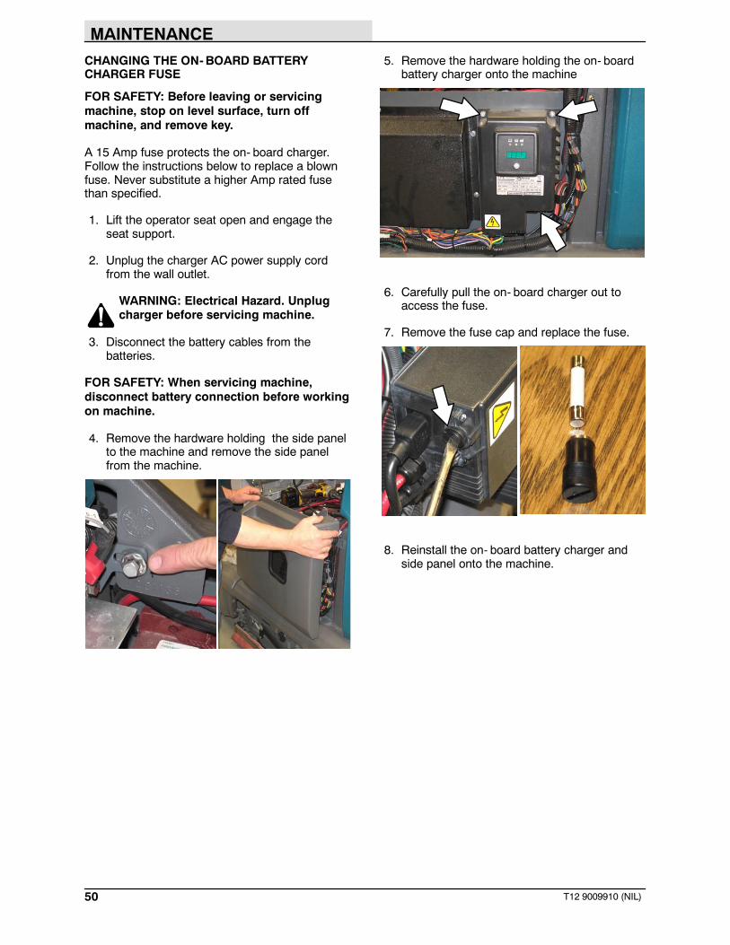
CHANGING THE ON-BOARD BATTERYCHARGER FUSE
FOR SAFETY: Before leaving or servicingmachine, stop on level surface, turn offmachine, and remove key.
A 15 Amp fuse protects the on- board charger.Follow the instructions below to replace a blownfuse. Never substitute a higher Amp rated fusethan specified.
1. Lift the operator seat open and engage theseat support.
2. Unplug the charger AC power supply cordfrom the wall outlet.
WARNING: Electrical Hazard. Unplugcharger before servicing machine.
3. Disconnect the battery cables from thebatteries.
FOR SAFETY: When servicing machine,disconnect battery connection before workingon machine.
4. Remove the hardware holding the side panelto the machine and remove the side panelfrom the machine.
5. Remove the hardware holding the on- boardbattery charger onto the machine
6. Carefully pull the on- board charger out toaccess the fuse.
7. Remove the fuse cap and replace the fuse.
8. Reinstall the on- board battery charger andside panel onto the machine.

MAINTENANCE
51T12 9009910 (1- 2013)
FLOW-RITEt BATTERY WATERING SYSTEM(OPTION)
The optional Flow- Rite battery watering systemprovides a safe and easy way to maintain theproper electrolyte levels in the batteries.
Check the battery watering system hoses andconnections for damage or wear after every 100hours.
FOR SAFETY: Before leaving or servicingmachine, stop on level surface, turn offmachine, and remove key.
1. Lift the operator seat open and engage theseat support.
2. Fully charge batteries prior to using thebattery watering system. Do not add water tobatteries before charging, the electrolyte levelwill expand and may overflow when charging.See CHARGING THE BATTERIES(OFF-BOARD CHARGER) or CHARGINGTHE BATTERIES (ON-BOARD CHARGER).
3. Connect the water supply hose to the fillregulator.
NOTE: Water quality is important to maintain thelife of the battery. Always use water that meetsbattery manufacturer requirements.
NOTE: The water supply to the battery watersystem must always be 7.57 LPM (2 GPM) ormore. Use the purger to confirm the water supplypressure. Refer to Flow-Rite Operator Manual foradditional information.
4. Remove the dust cover from the battery filltube and connect the fill regulator.

MAINTENANCE
52 T12 9009910 (1- 2013)
5. Turn on the water supply. The red balls insidethe flow indicator will spin. The red balls stopspinning when the batteries are full.
6. Disconnect the battery fill tube from the fillregulator.
7. Turn off the water supply.
8. After adding water, replace the dust cap onthe battery fill hose and return the fill regulatorto the storage location for future use.

MAINTENANCE
53T12 9009910 (11- 2015)
HYDROLINK BATTERY WATERING SYSTEM(OPTION)
The following instructions are for models equippedwith the HydroLINK battery watering systemoption.
The optional HydroLINK battery watering systemprovides a safe and easy way to maintain theproper electrolyte levels in your batteries. It isdesigned exclusively for Trojan wet/lead- acidbatteries.
Check the battery watering system hoses andconnections for damage or wear after every 100hours.
FOR SAFETY: Before leaving or servicingmachine, stop on level surface, turn offmachine, and remove key.
1. Lift the operator seat open and engage theseat support.
2. Fully charge batteries prior to using thebattery watering system. Do not add water tobatteries before charging, the electrolyte levelwill expand and may overflow when charging.See CHARGING THE BATTERIES(OFF-BOARD CHARGER) or CHARGINGTHE BATTERIES (ON-BOARD CHARGER).
3. After charging batteries, check the batteryelectrolyte level indicators located on thebattery covers. If the level indicator is whiteadd water as described in the followinginstructions. If the level indicators are blackthe electrolyte is at the correct level, no wateris required.
4. Locate the battery fill hose coupler inside thebattery compartment. Remove the dust capand connect the hand pump hose.
5. Submerge the other end of the hand pumphose into a bottle of distilled water.
DistilledWater

MAINTENANCE
54 T12 9009910 (7- 2013)
6. Squeeze the bulb on the hand pump hoseuntil firm. The level indicators will turn blackwhen full.
7. After adding water, replace the dust cap onthe battery fill hose and store the hand pumphose inside the machine’s batterycompartment for future use.
MAINTENANCE
55T12 9009910 (1- 2013)
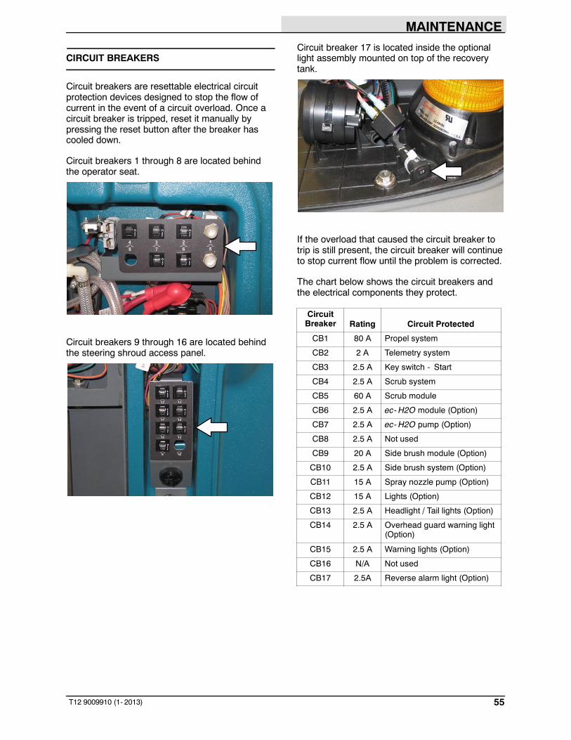
CIRCUIT BREAKERS
Circuit breakers are resettable electrical circuitprotection devices designed to stop the flow ofcurrent in the event of a circuit overload. Once acircuit breaker is tripped, reset it manually bypressing the reset button after the breaker hascooled down.
Circuit breakers 1 through 8 are located behindthe operator seat.
Circuit breakers 9 through 16 are located behindthe steering shroud access panel.
Circuit breaker 17 is located inside the optionallight assembly mounted on top of the recoverytank.
If the overload that caused the circuit breaker totrip is still present, the circuit breaker will continueto stop current flow until the problem is corrected.
The chart below shows the circuit breakers andthe electrical components they protect.
CircuitBreaker Rating Circuit Protected
CB1 80 A Propel system
CB2 2 A Telemetry system
CB3 2.5 A Key switch - Start
CB4 2.5 A Scrub system
CB5 60 A Scrub module
CB6 2.5 A ec- H2O module (Option)
CB7 2.5 A ec- H2O pump (Option)
CB8 2.5 A Not used
CB9 20 A Side brush module (Option)
CB10 2.5 A Side brush system (Option)
CB11 15 A Spray nozzle pump (Option)
CB12 15 A Lights (Option)
CB13 2.5 A Headlight / Tail lights (Option)
CB14 2.5 A Overhead guard warning light(Option)
CB15 2.5 A Warning lights (Option)
CB16 N/A Not used
CB17 2.5A Reverse alarm light (Option)

MAINTENANCE
56 T12 9009910 (7- 2013)
ELECTRIC MOTORS
Inspect the carbon brushes on the vacuum fanmotor after every 500 hours of operation. Inspectthe carbon brushes on the main brush motors andside brush motor after the first 1000 hours ofoperation and every 100 hours after the initialcheck. Refer to the table below for carbon brushinspection intervals.
Carbon Brush Inspection Hours
Main Brush Motors 1000*
Side Brush Motor (Option) 1000*
Vacuum Motor 500
*Inspect carbon brushes every 100 hours after theinitial 1000 hour change.

MAINTENANCE
57T12 9009910 (11- 2015)
SCRUB BRUSHES
The machine can be equipped with either disk orcylindrical scrub brushes. Check scrub brushesdaily for wire or string tangled around the brush orbrush drive hub. Also check brushes or pads fordamage and wear.
DISK BRUSHES AND PADS
Replace the pads when they no longer cleaneffectively. Replace the brushes when they nolonger clean effectively or when the bristles areworn to the yellow indicator.
Cleaning pads must be placed on pad driversbefore they are ready to use. The cleaning pad isheld in place with a center disk. Both sides of thepad can be used for scrubbing. Turn the pad overto use the other side.
Cleaning pads need to be cleaned immediatelyafter use with soap and water. Do not wash thepads with a pressure washer. Hang pads, or laypads flat to dry.
NOTE: Always replace brushes and pads in sets.Otherwise one brush or pad will be moreaggressive than the other.
REPLACING DISK BRUSHES OR PADDRIVERS
1. Raise the scrub head.
2. Turn off the machine.
FOR SAFETY: Before leaving or servicingmachine, stop on level surface, turn offmachine, and remove key.
3. Open the main brush access door and sidesqueegee support door.
4. Turn the brush until the spring handles arevisible.
5. Squeeze the spring handles and let the brushdrop to the floor. Remove the brush fromunder the scrub head.

MAINTENANCE
58 T12 9009910 (11- 2015)
6. Set the brush spring open on the new brushto make installation easier.
7. Push the new brush under the scrub head,align the brush drive socket with the brushdrive hub, and lift the brush up onto the brushdrive hub until the brush locks onto the hub.
8. Ensure the brush is securely mounted on thebrush drive hub.
9. Close and secure the squeegee support doorand close the main brush access door.
10. Repeat procedure for the other brush.
REPLACING DISK SCRUB PADS
1. Remove the pad driver from the machine.
2. Squeeze the spring clip together and removethe center disk from the pad driver.
3. Remove the scrub pad from the pad driver.
4. Flip or replace the scrub pad. Center thescrub pad on the pad driver and reinstall thecenter disk to secure the pad in place on thepad driver.
5. Reinstall the pad driver onto the machine.

MAINTENANCE
59T12 9009910 (7- 2013)
CYLINDRICAL BRUSHES
Rotate the brushes from front-to-rear after every50 hours of operation.
Replace the brushes when they no longer cleaneffectively.
NOTE: Replace worn brushes in pairs. Scrubbingwith brushes of unequal bristle length will result indiminished scrubbing performance.
REPLACING CYLINDRICAL SCRUB BRUSHES
FOR SAFETY: Before leaving or servicingmachine, stop on level surface, turn offmachine, and remove key.
1. Open the main brush access door and sidesqueegee support door.
2. Remove the idler plate from the scrub head.
3. Remove the brush from the scrub head
4. Position the brush with the double row endtowards the scrub head opening. Guide thenew brush onto the drive hub.
5. If rotating the brushes, always rotate the frontwith the back so that they wear evenly. Theymay be rotated end for end as well.
Before After
A B AB
6. Reinstall the idler plate onto the scrub head.
NOTE: Do not switch the left or right idler platesor the brushes will need to be readjusted bytrained personnel.
7. Close and secure the squeegee support doorand close the main brush access door.
8. Repeat for the brush on the other side of thescrub head.

MAINTENANCE
60 T12 9009910 (11- 2015)
SIDE BRUSH (OPTION)
FOR SAFETY: Before leaving or servicingmachine, stop on level surface, turn offmachine, and remove key.
Check the side brush daily for wear or damage.Remove any tangled string or wire from the sidebrush or side brush drive hub.
REPLACING THE SIDE BRUSH
Replace the pads when they no longer cleaneffectively. Replace the brushes when they nolonger clean effectively or when the bristles areworn to the yellow indicator.
1. Loosen the side brush squeegee assemblyhandle and remove the squeegee assemblyfrom the machine.
2. Squeeze the spring handles and let the sidebrush drop to the floor.
3. Remove the side brush from under the sidebrush assembly.
4. Set the brush spring open on the new brushto make installation easier.
5. Place the new side brush underneath the sidebrush assembly and lift the side brush up ontothe side brush hub until the brush locks ontothe hub.
6. Reinstall the side brush squeegee assemblyonto the side brush assembly.
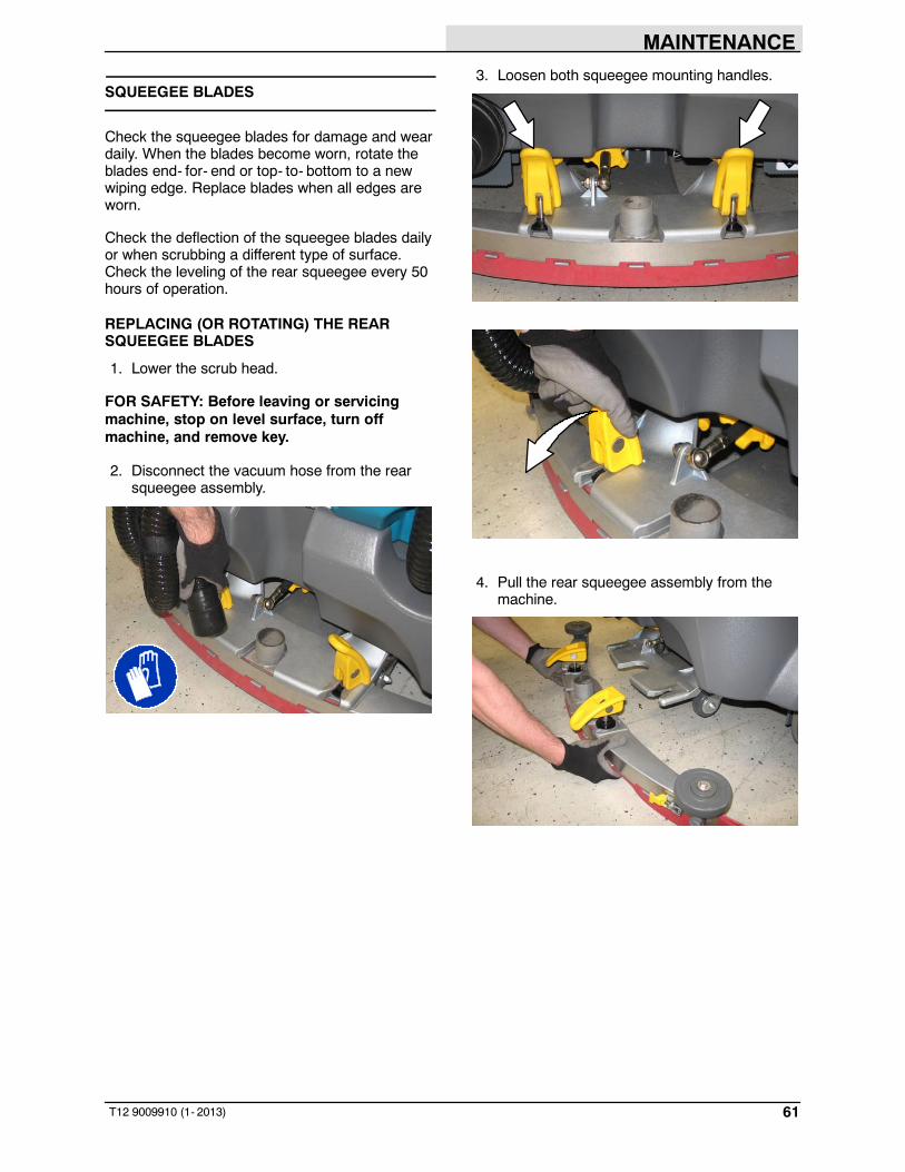
MAINTENANCE
61T12 9009910 (1- 2013)
SQUEEGEE BLADES
Check the squeegee blades for damage and weardaily. When the blades become worn, rotate theblades end- for- end or top- to- bottom to a newwiping edge. Replace blades when all edges areworn.
Check the deflection of the squeegee blades dailyor when scrubbing a different type of surface.Check the leveling of the rear squeegee every 50hours of operation.
REPLACING (OR ROTATING) THE REARSQUEEGEE BLADES
1. Lower the scrub head.
FOR SAFETY: Before leaving or servicingmachine, stop on level surface, turn offmachine, and remove key.
2. Disconnect the vacuum hose from the rearsqueegee assembly.
3. Loosen both squeegee mounting handles.
4. Pull the rear squeegee assembly from themachine.

MAINTENANCE
62 T12 9009910 (1- 2013)
5. Loosen the retainer latch and remove theretainer from the squeegee assembly.
6. Remove the squeegee from the squeegeeassembly.
7. Slide both retainers out away from thesqueegee assembly.
8. Remove the inner frame from the outer frame.
9. Remove the squeegee from the outer frame.
10. Install the rotated or new squeegee blade intothe outer frame. Be sure the squeegee iscompletely slid down onto each tab on theouter frame.

MAINTENANCE
63T12 9009910 (1- 2013)
11. Install the inner frame over the squeegee andonto the outer frame. Be sure the inner frameis tight against the top of the outer frame.
12. Slide both retainers into the squeegeeassembly.
13. Place the rotated or new squeegee blade ontothe inner frame. Be sure the squeegee issecurely attached on each tab on the innerframe.
14. Insert the hinge end of the retainer into thehooks in the inner frame.
15. Install the retainer along the rest of thesqueegee assembly and fasten the latch ontothe other end of the squeegee assembly.
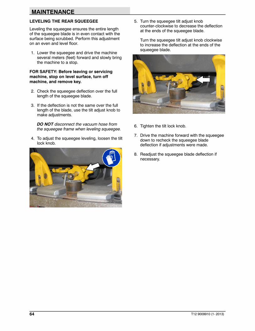
MAINTENANCE
64 T12 9009910 (1- 2013)
LEVELING THE REAR SQUEEGEE
Leveling the squeegee ensures the entire lengthof the squeegee blade is in even contact with thesurface being scrubbed. Perform this adjustmenton an even and level floor.
1. Lower the squeegee and drive the machineseveral meters (feet) forward and slowly bringthe machine to a stop.
FOR SAFETY: Before leaving or servicingmachine, stop on level surface, turn offmachine, and remove key.
2. Check the squeegee deflection over the fulllength of the squeegee blade.
3. If the deflection is not the same over the fulllength of the blade, use the tilt adjust knob tomake adjustments.
DO NOT disconnect the vacuum hose fromthe squeegee frame when leveling squeegee.
4. To adjust the squeegee leveling, loosen the tiltlock knob.
5. Turn the squeegee tilt adjust knobcounter-clockwise to decrease the deflectionat the ends of the squeegee blade.
Turn the squeegee tilt adjust knob clockwiseto increase the deflection at the ends of thesqueegee blade.
6. Tighten the tilt lock knob.
7. Drive the machine forward with the squeegeedown to recheck the squeegee bladedeflection if adjustments were made.
8. Readjust the squeegee blade deflection ifnecessary.

MAINTENANCE
65T12 9009910 (1- 2013)
ADJUSTING THE REAR SQUEEGEE BLADEDEFLECTION
Deflection is the amount of curl the overallsqueegee blade has when the machine movesforward. The best deflection is when thesqueegee wipes the floor dry with a minimalamount of deflection.
NOTE: Make sure the squeegee is level beforeadjusting the deflection. See LEVELING THEREAR SQUEEGEE.
1. Lower the squeegee and drive the machineseveral meters (feet) forward and slowly bringthe machine to a stop.
FOR SAFETY: Before leaving or servicingmachine, stop on level surface, turn offmachine, and remove key.
2. Look at the amount of deflection or “curl” ofthe squeegee blade. The correct amount ofdeflection is 12 mm (0.50 in) for scrubbingsmooth floors and 15 mm (0.62 in) for roughfloors.
3. To adjust the overall squeegee bladedeflection, loosen the lock knob.
4. Turn the adjustment knobs counterclockwiseto increase deflection or clockwise todecrease deflection.
5. Retighten the lock knob.
6. Drive the machine forward again to recheckthe squeegee blade deflection.
7. Readjust the squeegee blade deflection ifnecessary.

MAINTENANCE
66 T12 9009910 (1- 2013)
REPLACING OR ROTATING THE SIDESQUEEGEE BLADES
1. If necessary, raise the scrub head.
FOR SAFETY: Before leaving or servicingmachine, stop on level surface, turn offmachine, and remove key.
2. Open the main brush access door and sidesqueegee support door.
3. Unhook the retaining band latch from the sidesqueegee assembly.
4. Remove the retaining band from the sidesqueegee assembly.
5. Remove the squeegee blade from the sidesqueegee assembly.
6. Install the rotated or new rear squeegee bladeonto the side squeegee assembly.
7. Hook the retaining band onto the retainingband retainer tab on the side squeegeeassembly.
8. Fasten the retaining band latch onto the sidesqueegee assembly.
9. Close and secure the squeegee support doorand close the main brush access door.
10. Repeat for the side squeegee on the otherside of the scrub head.

MAINTENANCE
67T12 9009910 (1- 2013)
REPLACING OR ROTATING THE SIDEBRUSH SQUEEGEE BLADES (OPTION)
FOR SAFETY: Before leaving or servicingmachine, stop on level surface, turn offmachine, and remove key.
Check the side brush squeegee blade for damageand wear daily. Replace or rotate the blade if theleading edge is torn or worn half-way through thethickness of the blade.
1. Loosen the side brush squeegee assemblyhandle and remove the squeegee assemblyfrom the machine.
2. Loosen the retaining band latch.
3. Remove the retaining band, squeegee blades,and spacer from the squeegee frame.
NOTE: Observe which squeegee slots wereinstalled on the squeegee frame before removingthe squeegee.
NOTE: The squeegee blade(s) have two sets ofslots for adjusting the squeegee blade deflection.Install / reinstall squeegees so the deflection isapproximately 12 mm (0.50 in) for smooth floorsand 15 mm (0.62 in) for rough floors.

MAINTENANCE
68 T12 9009910 (1- 2013)
4. Install the rotated / new squeegee blades,spacer, and retaining band onto the sidebrush assembly.
5. Fasten the side brush retaining band latch.
6. Reinstall the side brush squeegee assemblyonto the side brush assembly.

MAINTENANCE
69T12 9009910 (1- 2013)
SKIRTS AND SEALS
FOR SAFETY: Before leaving or servicingmachine, stop on level surface, turn offmachine, and remove key.
RECOVERY TANK SEAL
Check the recovery tank cover seal for damageand wear daily.
SCRUB HEAD SKIRTS (DISK SCRUB HEADSONLY)
Check the scrub head skirts for damage and wearafter every 50 hours of operation.
BELTS
CYLINDRICAL BRUSH DRIVE BELTS
FOR SAFETY: Before leaving or servicingmachine, stop on level surface, turn offmachine, and remove key.
The brush drive belts are located on thecylindrical brush scrub head. Check the belts fordamage and wear after every 200 hours ofoperation.
TIRES
FOR SAFETY: Before leaving or servicingmachine, stop on level surface, turn offmachine, and remove key.
The machine has three solid rubber tires: one infront, and two in the rear of the machine. Checktires for damage and wear after every 500 hoursof operation.

MAINTENANCE
70 T12 9009910 (11- 2019)
PUSHING, TOWING, AND TRANSPORTINGTHE MACHINE
PUSHING OR TOWING THE MACHINE
If the machine becomes disabled, it can bepushed or towed from the front or rear.
The parking brake must be disabled before towingor pushing the machine. To disable the brake,insert the tip of a small screw driver between theelectronic brake lever and the hub. The machinecan move freely when the parking brake isdisabled.
Only push or tow the machine for a very shortdistance and do not exceed 3.2 kp/h (2 mph). It isNOT intended to be pushed or towed for a longdistance or at a high speed.
ATTENTION! Do not push or tow machine fora long distance or damage may occur to thepropelling system.
Immediately after pushing the machine, removethe screw driver from between the electronicbrake lever and the hub. NEVER operate themachine with the parking brake disabled.
FOR SAFETY: Do not operate machine withbrake disabled.
TRANSPORTING THE MACHINE
FOR SAFETY: When transporting Lithium- ionBattery Model, contact Tennant or your localregulatory authorities for proper transportinginstructions.
1. Raise the squeegee, scrub head, andbrushes.
FOR SAFETY: When loading/unloadingmachine onto/off truck or trailer, drain tanksbefore loading machine.
2. Position the machine at the loading edge ofthe truck or trailer.
3. If the loading surface is not horizontal or ishigher than 380 mm (15 in) from the ground,use a winch to load machine.
If the loading surface is horizontal AND is380 mm (15 in) or less from the ground, themachine may be driven onto the truck ortrailer.
FOR SAFETY: When loading machine ontotruck or trailer, use winch. Do not drive themachine onto the truck or trailer unless theloading surface is horizontal AND is 380 mm(15 in) or less from the ground.
4. To winch the machine onto the truck or trailer,attach the winching chains to the stabilizerlegs.
5. Position the machine as close to the front ofthe trailer or truck as possible. If the machinestarts to veer off the center line of the truck ortrailer, stop and turn the steering wheel tocenter the machine.

MAINTENANCE
71T12 9009910 (7- 2013)
6. Place a block behind each wheel to preventthe machine from rolling.
7. Lower the scrub head and turn off machine.
FOR SAFETY: When loading/unloadingmachine onto/off truck or trailer, lower scrubhead and squeegee before tying downmachine.
8. Connect the tie- down straps to the right andleft stabilizer bars in front of the machine andthe holes in the rear jacking brackets at therear of the machine.
9. If the loading surface is not horizontal or ishigher than 380 mm (15 in) from the ground,use a winch to unload machine.
If the loading surface is horizontal AND is380 mm (15 in) or less from the ground, themachine may be driven off the truck or trailer.
FOR SAFETY: When unloading machine offtruck or trailer, use winch. Do not drive themachine off the truck or trailer unless theloading surface is horizontal AND 380 mm(15 in) or less from the ground.

MAINTENANCE
72 T12 9009910 (1- 2013)
MACHINE JACKING
FOR SAFETY: Before leaving or servicingmachine, stop on level surface, turn offmachine, and remove key.
Empty the recovery and solution tanks beforejacking the machine.
Jacking point location at the front of all machines.
Jacking point location at the rear of machines notequipped with the optional rear squeegeeprotector.
Jacking point location at the rear of machinesequipped with the optional rear squeegeeprotector.
FOR SAFETY: When servicing machine, blockmachine tires before jacking machine up. Usea hoist or jack that will support the weight ofthe machine. Jack machine up at designatedlocations only. Support machine with jackstands.

MAINTENANCE
73T12 9009910 (1- 2013)
ec-H2O MODULE FLUSH PROCEDURE
This procedure is only required when an alarmsounds and the ec-H2O system indicator lightbegins to blink.
FOR SAFETY: Before leaving or servicingmachine, stop on level surface and turn offmachine.
1. Lift the operator seat open and engage theseat support.
2. Remove the drain hose from the ec-H2Ocompartment.
3. Press the connector button to disconnect theoutlet hose from the ec-H2O manifold.
4. Connect the drain hose to the ec-H2Omanifold hose disconnected from the ec-H2Omanifold in the previous step.
5. Place the drain hose into a empty container.
6. Pour 2 gallons (7.6 liters) of white or ricevinegar into the solution tank.

MAINTENANCE
74 T12 9009910 (1- 2013)
7. Start the machine.
8. Press and release the ec-H2O module flushswitch to start the flush cycle.
NOTE: The module will automatically shut offwhen the flush cycle is complete (approximately 7minutes). The module must run the full 7-minutecycle in order to reset the system indicator lightand alarm.
9. Pour 2 gallons (7.6 liters) of cool clean waterinto the solution tank.
10. Press and release the flush switch to rinseany remaining vinegar from the module. After1- 2 minutes, press the flush switch to turn offthe module.
11. Disconnect the drain hose from the ec-H2Omanifold hose.
12. Reconnect the outlet hose to the the scrubhead to the ec-H2O manifold.
13. Place the drain hose back into the ec-H2Ocompartment.
14. Close the operator seat.

MAINTENANCE
75T12 9009910 (11- 2019)
STORAGE INFORMATION
The following steps should be taken when storingthe machine for extended periods of time.
1. Charge the batteries before storing machineto prolong the life of the batteries. Rechargelead- acid batteries once a month. RechargeLithium- ion Battery Pack once a year.
2. Disconnect batteries before storing.
3. Thoroughly drain and rinse the solution andrecovery tanks.
4. Store the machine in a dry area with thesqueegee and scrub head in the up position.
ATTENTION: Do not expose machine to rain,store indoors.
5. Open the recovery tank cover to promote aircirculation.
6. If storing machine in freezing temperatures,proceed to FREEZE PROTECTION.
NOTE: To prevent potential machine damagestore machine in a rodent and insect freeenvironment.
FREEZE PROTECTION
FOR SAFETY: Before leaving or servicingmachine, stop on level surface and turn offmachine.
FOR SAFETY: When storing Lithium- ionBattery Model, do not expose battery totemperatures below - 22F/- 30C, above140F/60C. Do not use machine immediatelyafter long- term extreme temperature storage.Before use, return battery moduletemperature range to 50F/10C~95F/35C
1. Completely drain the solution tank andrecovery tank.
2. Pour 7.6 L (2 gal) of Propylene Glycol Based /Recreational Vehicle (RV) antifreeze into thesolution tank.
3. Turn on the machine.
4. Press the 1- Step button.
T12 T12XP
5. Repeatedly press the Solution increase button(+) until the solution flow is at the highestsetting.
T12 T12XP

MAINTENANCE
76 T12 9009910 (1- 2013)
6. Machines with ec-H2O option only: Pressthe scrub mode button to place machine intothe ec-H2O mode. The ec-H2O indicatorlight will illuminate.
T12 T12XP
7. Machines with side brush option only:Press the side brush switch to activate theside brush.
T12
T12XP
8. Drive the machine to circulate the RVantifreeze completely through all the systemsand clear out any remaining water.
9. Machines with side brush option only:Press the side brush switch to turn off theside brush.
10. Stop the machine.
11. Machines with spray nozzle option only:Operate the wand for a few seconds toprotect the pump.
12. Press the 1- STEP button to turn off thesystem.
13. Turn off the machine.
14. The remaining RV antifreeze does not need tobe drained from the solution or recovery tank.

MAINTENANCE
77T12 9009910 (1- 2013)
PREPARING THE MACHINE FOR OPERATIONAFTER STORAGE
All Propylene Glycol Based / Recreational Vehicle(RV) Antifreeze must be completely cleaned fromthe scrubbing system before the machine can beused for scrubbing.
FOR SAFETY: Before leaving or servicingmachine, stop on level surface and turn offmachine.
1. Completely drain all Propylene Glycol Based /Recreational Vehicle (RV) antifreeze from thesolution tank.
2. Rinse out the solution tank. Refer toDRAINING AND CLEANING THE SOLUTIONTANK in the OPERATION section forinstructions how to clean the solution tank.
3. Pour 11.4 L (3 gal) of cool clean water into thesolution tank.
4. Start the machine
5. Press the 1- STEP button.
T12 T12XP
6. Repeatedly press the Solution increase button(+) until the solution flow is at the highestsetting.
T12
T12XP
7. Machines with ec-H2O option only: Pressthe scrub mode button to place machine intothe ec-H2O mode. The indicator light willilluminate.
T12 T12XP
NOTE: The ec-H2O systems on machinesequipped with ec-H2O must be primed before themachine is ready for operation. See PRIMINGTHE ec-H2O SYSTEM for additional instructions.

MAINTENANCE
78 T12 9009910 (1- 2013)
8. Machines with side brush option only:Press the side brush switch to activate theside brush.
T12
T12XP
9. Drive the machine to circulate the clean watercompletely through the system and clear outthe RV antifreeze.
10. Machines with side brush option only:Press the side brush switch to turn off theside brush.
11. Stop the machine.
12. Machines with spray nozzle option only:Operate the wand for a few seconds to cleanthe RV antifreeze from the pump.
13. Press the 1- STEP button to turn off thesystem.
14. Turn off the machine.
15. The remaining water does not need to bedrained from the solution tank.

MAINTENANCE
79T12 9009910 (1- 2013)
PRIMING THE ec-H2O SYSTEM
Prime the ec-H2O system if the machine hasbeen stored for a long period with no water in thesolution tank / ec-H2O system.
FOR SAFETY: Before leaving or servicingmachine, stop on level surface and turn offmachine.
1. Fill the solution tank with clean cool water.See FILLING THE SOLUTION TANK sectionof this manual.
2. Lift the operator seat open and engage theseat support.
3. Remove the drain hose from the ec-H2Ocompartment.
4. Disconnect the outlet hose to the scrub headfrom the ec-H2O manifold.
5. Place the drain hose into an empty container.
6. Connect the drain hose to the ec-H2Omanifold hose disconnected from the outlethose in the previous step.
7. Place the ec-H2O system outlet hose into anempty container.
8. Start the machine.
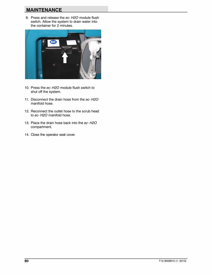
MAINTENANCE
80 T12 9009910 (1- 2013)
9. Press and release the ec-H2O module flushswitch. Allow the system to drain water intothe container for 2 minutes.
10. Press the ec-H2O module flush switch toshut off the system.
11. Disconnect the drain hose from the ec-H2Omanifold hose.
12. Reconnect the outlet hose to the scrub headto ec-H2O manifold hose.
13. Place the drain hose back into the ec-H2Ocompartment.
14. Close the operator seat cover.

SPECIFICATIONS
81T12 9009910 (5- 2016)
SPECIFICATIONS
GENERAL MACHINE DIMENSIONS/CAPACITIES
Item Dimension/capacity
Length 1710 mm (67.25 in)
Width (less squeegee) 945 mm (37.25 in)
Width (with squeegee) 990 mm (39 in)
Width (with side brush) 1065 mm (42 in)
Height 1420 mm (56 in)
Height with overhead guard 2095 mm (82.5 in)
Disk brush diameter for side brush (option) 330 mm (13 in)
Disk brush diameter 405 mm (16 in)
Cylindrical brush diameter 180 mm (7 in)
Cylindrical brush length 780 mm (30.7 in)
Scrubbing path width 810 mm (32 in)
Scrubbing path width (with side brush) 1040 mm (41 in)
Solution tank capacity 132 L (35 gallons)
Recovery tank capacity 166 L (44 gallons)
Demisting chamber 34 L (9 gallons)
Weight (Empty) 468 Kg (1030 lbs)
Weight (with standard 240 AH lead- acid batteries) 664 Kg (1460 lbs)
GVWR 1000 Kg (2200 lbs)
Protection Grade IPX3
Values determined as per IEC60335- 2- 72
Measure -Cylindrical scrub head
Measure -Disk scrub head
Sound pressure level LpA 63 dB(A) 62 dB(A)
Sound uncertainty KpA 3.0 dB(A) 3.0 dB(A)
Sound power level LWA + Uncertainty KWA 86.5 dB(A) 87.5 dB(A)
Vibration - Hand- arm 1.65 m/s2 1.65 m/s2
Vibration - Whole body 0.32 m/s2 0.32 m/s2
Vibration uncertainty K 0.20 m/s2 0.20 m/s2

SPECIFICATIONS
82 T12 9009910 (11- 2019)
GENERAL MACHINE PERFORMANCE
Item Measure
Aisle turnaround width 1854 mm (73 in)
Travel Speed (Forward) 8 Km (5 mph)
Travel Speed while scrubbing (Forward) 6.1 Km (3.8 mph)
Travel Speed (Reverse) 4 Km (2.5 mph)
Maximum ramp incline for loading - Empty tanks 20% / 11_
Maximum ramp incline for scrubbing 7% / 4_
Maximum ramp incline for transporting (GVWR) 14% / 8_
Maximum ambient temperature for machine operation 43_ C (110_ F)
Minimum temperature for operating machine scrubbing functions 0_ C (32_ F)
POWER TYPE
Type Quantity Volts Ah Rating Weight
Lead- acid Batteries (Max. batterydimensions: 177.8 mm (7 in) W x 299.7mm (11.8 in) L x 380 mm (15 in) H)
6 36 240 @ 20 hr rate 30 kg (67 lb)
6 36 360 @ 20 hr rate 44 kg (97 lb)
Lithium- ion Battery 2 pack 36 110 / 4.1 kWh 51 Kg (112 lb)
4 pack 36 221 / 8.2 kWh 83 Kg (183 lb)
5 pack 36 276 / 10.2 kWh 98 Kg (217 lb)
Type Use VDC kW (hp)
Electric Motors Scrub brush (disk) 36 0.75 (1.00)
Scrub brush (cylindrical) 36 0.75 (1.00)
Vacuum fan 36 0.6 (0.8)
Propelling 36 0.9 (1.2)
Type VDC amp Hz Phase W VAC
Charger (On- board) 36 20 50- 60 1 720 115- 240
Charger (Off- board) 36 21 45- 65 1 756 85- 265
Charger, Lithium- ion Battery(Standard, Off- board)
36 25 50- 60 1 900 100- 240
Charger, Lithium- ion Battery(Fast, Off- board)
36 33 50- 60 1 1200 100- 240
TIRESLocation Type Size
Front (1) Solid 90 mm wide x 250 mm OD (3.5 in wide x 10 in OD)
Rear (2) Solid 102 mm wide x 300 mm OD (4 in wide x 12 in OD)
STANDARD SOLUTION FLOW RATE
Item Measure
Solution pump 36 Volt DC, 4.01 LPH (1.06 GPM) maximum

SPECIFICATIONS
83T12 9009910 (11- 2019)
SIDE BRUSH SOLUTION FLOW RATE (OPTION)Item Measure
Solution pump 36 Volt DC 0.95 LPM (0.25 GPM) maximum
ec-H2O SYSTEM (OPTION)Item Measure
Solution pump 36 Volt DC, 5.13 LPM (1.36 GPM) min open flow
Solution flow rate (machines without optional sidebrush)
1.9 LPM (0.5 GPM) maximum
Solution flow rate (machines with optional sidebrush)
1.9 LPM (0.5 GPM) - (To main scrub head)
0.95 LPM (0.25 GPM) - (To side brush)
MACHINE DIMENSIONS
Frame(roller to roller)945 mm (37.25 in)
1420 mm(56 in)
1710 mm(67.25 in)
RearSqueegee990 mm(39 in)
Width(with side brush)1065 mm (42 in)
2095 mm(82.5 in)
356389

INDEX
84 T12 9009910 (11- 2019)
1
1- STEP button, 20, 24, 25, 26, 27, 28
A
Adjust operator seat, 18
Adjusting the Rear Squeegee Blade Deflection,65
Alarms, 33Fault Indicators, 33
B
Batteries, 45Changing on- board battery charger fuse, 50Charging batteries (off- board charger), 46Charging batteries (on- board charger), 47Checking connections / cleaning, 45Checking the electrolyte level, 45Flooded (wet) and Maintenance- Free Sealed
lead- acid Batteries, 45Lithium- ion Battery Pack, 46Flow- Rite battery watering system (option), 51Hydrolink Battery Watering System (option), 53Installing Batteries, 15Flooded/Sealed Lead- acid Batteries, 15Lithium- ion Battery, 16
Maintenance, 45On- board battery charger error codes, 48On- board battery charger settings, 49
Battery discharge indicator, 16
Battery Specifications, 15
Belts, 69Cylindrical brush drive belt, 69
Belts and Chains, Cylindrical brush drive belt, 69
Brake pedal, 19
Brush and Pad Information, 21
Brush Information, 21
Brush pressure decrease button, 25
Brush pressure increase button, 25
Buttons1- STEP button, 26Brush pressure decrease button, 25Brush pressure increase button, 25Configuration mode button, 19Contrast control button, 19ec- H2O button, 24Solution decrease button, 25Solution increase button, 25Solution on / off buttons, 20Vacuum fan / squeegee, 20Vacuum fan/squeegee button, 27, 28
C
Capacities, 81
Changing on- board battery charger fuse, 50
Circuit breakers, 55
Configuration mode button, 19
Contrast control button, 19
Controls1- STEP button, 26Brush pressure decrease button, 25Brush pressure increase button, 25Circuit breakers, 55Directional switch, 19ec- H2O button, 24Emergency shut- off button, 17Key switch, 23Operating / hazard light switch (Option), 17Scrub mode button, 20Side brush switch (option), 38Solution decrease button, 25Solution increase button, 25Solution on / off buttons, 20Spray nozzle switch (option), 35
Controls and Instruments, 13Touch Panel (Standard), 11Touch Panel (XP), 13
Controls and Instruments (Standard), 10
Controls and Instruments (XP), 12
Cylindrical brushes, Replacing brushes, 59
D
Debris trough, 30
Dimensions, 81
Directional switch, 19
Disable the parking brake, 70
Disk Brush, Replacing, 57
Disk brushes, 57 - 62
Disk Pads, Replace, 58
Disk Scrub Brushes, Replacing, 57
Disk Scrub Pads, Replace, 58
Double Scrubbing, 27
Draining and Cleaning the Recovery Tank, 29
Draining and Cleaning the Solution Tank, 31
E
ec- H20 Scrubbing System, Indicator LightCodes, 26

INDEX
85T12 9009910 (11- 2019)
ec- H20 Scrubbing System Indicator LightCodes , 26
ec- H20 System, Specifications, 83
ec- H2O button, 24
ec- H2O Module Flush Procedure, 73
Electric motors, 56
Electrical systemBatteries, 45Checking connections / cleaning, 45Checking the electrolyte level, 45Flooded (wet) and Maintenance- Free Sealed
lead- acid Batteries, 45Lithium- ion Battery Pack, 46
Changing on- board battery charger fuse, 50Charging batteries (off- board charger), 46Charging batteries (on- board charger), 47Circuit breakers, 55Electric motors, 56On- board battery charger settings, 49
Emergency shut- off button, 17
Error codes, On- board battery charger, 48
F
Fault Indicators, 33
Filling the Solution Tank, 23Conventional Scrubbing Mode, 24ec- H20 scrubbing (ec- H20 Mode), 23
Flow- Rite battery watering system (option), 51
Flush Procedure, ec- H2O Module, 73
Freeze Protection, 75
H
Hour Meter, 16
How the Machine Works, 20
Hydrolink Battery Watering System (option), 53
I
Indicator Light Codes, ec- H20 ScrubbingSystem, 26
IndicatorsBattery discharge, 16Fault Indicators, 33Hour Meter, 16Recovery tank full, 16Warning codes, 34
K
Key switch, 23
L
Leveling the Rear Squeegee, 64
Lights, Operating / hazard light switch (Option),17
Lithium- ion Battery Pack, 46
Lubrication, 44Rear squeegee caster pivot points, 44Steering chain, 44Steering gear chain, 44
M
Machine components, 9
Machine Dimensions, 83
Machine Jacking, 72
Machine OperationDouble scrubbing, 27Pre- Operation Checklist, 22Scrubbing, 26Start the machine, 23Stop scrubbing, 28Turning off the machine, 32
Machine PerformanceAisle Turnaround Width, 82Climb and Descent Angles, 82Travel Speed (Maximum), 82
Machine Specifications, 81
Machine tie down location, 71
Machine Troubleshooting, 40
Maintenance, 42 - 66Batteries, 45Checking connections / cleaning, 45Checking the electrolyte level, 45Flooded (wet) and Maintenance- Free Sealed
lead- acid Batteries, 45Lithium- ion Battery Pack, 46
Belts, 69Charging batteries (off- board charger), 46Charging batteries (on- board charger), 47Changing on- board battery charger fuse, 50Circuit Breakers, 55Cylindrical brushes, 59 - 64Disk brushes, 57 - 62ec- H2O Module, 73Lubrication, 44Machine Jacking, 72On- board battery charger settings, 49Pushing, Towing, and Transporting the Machine,
70

INDEX
86 T12 9009910 (11- 2019)
Replacing cylindrical brushes, 59Side Brush (Option), 60Skirts and Seals, 69Squeegee Blades, 61Storage Information, 75Tires, 69Yellow touch points, 44
Maintenance Chart, 42
O
On- board battery charger error codes, 48 - 53
Operating / hazard light switch (Option), 17
Operating temperature, 22
Operation, 9 - 33
Operation of controls, 16
Operator seat, 18
Operator seat release handle (deluxe seat only),18
Options, 35 - 37Rear Squeegee Guard, 37Side brush, 38Spray Nozzle, 35Vacuum wand, 36
P
Pad Driver, Replacing, 57
Pad Information, 21
Parking brake, Disable the parking brake, 70
PedalsBrake pedal, 19Propel pedal, 19
Pre- Operation Checklist, 22
Preparing the machine for operation afterstorage, 77
Priming the ec- H20 system, 79
Propel pedal, 19
Pushing or Towing the Machine, 70
Pushing, Towing, and Transporting the Machine,70
Pushing or Towing the Machine, 70Transporting the Machine, 70
R
Rear SqueegeeAdjusting the Rear Squeegee Blade Deflection,
65Leveling the Rear Squeegee, 64
Rear Squeegee Blade, Replacing (or Rotating)the Rear Squeegee Blade, 61
Rear Squeegee Guard (option), 37
Rear Squeegee, Replacing (or Rotating), 61
Recovery tank full indicator, 16
Recovery Tank Seal, 69
Replacing (or Rotating) the Rear SqueegeeBlades, 61
Replacing or Rotating the Side Brush SqueegeeBlade (Option), 67
Replacing or Rotating the Side SqueegeeBlades, 66
Replacing the Side Brush (Option), 60
S
SafetyLabels, 7Lithium- ion Battery Label, 8Precautions, 4 - 6
Scrub brushesCylindrical brushes, 59Replacing cylindrical brushes, 59
Scrub Brushes and Pads, 57Disk brushes, 57Replacing Disk Brushes or Pad Driver, 57Replacing Disk Scrub Pads, 58
Scrub head skirt (Disk scrub heads only), 69
Scrubbing, 26Double scrubbing, 27Stop scrubbing, 28 - 30
Seals, 69Recovery Tank Seal, 69
Seat belts, 18
Seat support, 18
Seat, Operator, 18
Setting Brush Pressure, 25
Setting Scrub ModesSetting Brush Pressure, 25Setting Solution Flow, 25
Side Brush (Option), 38, 60Replacing or Rotating the Side Brush
Squeegee, 67Replacing the Side Brush, 60
Side Brush Squeegee (Option), Replacing orRotating, 67
Side Brush System, Specifications, 82
Side Brush, Replacing, 60
Side Squeegee Blades, 66
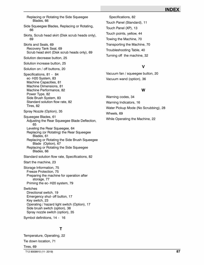
INDEX
87T12 9009910 (11- 2019)
Replacing or Rotating the Side SqueegeeBlades, 66
Side Squeegee Blades, Replacing or Rotating,66
Skirts, Scrub head skirt (Disk scrub heads only),69
Skirts and Seals, 69Recovery Tank Seal, 69Scrub head skirt (Disk scrub heads only), 69
Solution decrease button, 25
Solution increase button, 25
Solution on / off buttons, 20
Specifications, 81 - 84ec- H20 System, 83Machine Capacities, 81Machine Dimensions, 81Machine Performance, 82Power Type, 82Side Brush System, 83Standard solution flow rate, 82Tires, 82
Spray Nozzle (Option), 35
Squeegee Blades, 61Adjusting the Rear Squeegee Blade Deflection,
65Leveling the Rear Squeegee, 64Replacing (or Rotating) the Rear Squeegee
Blades, 61Replacing or Rotating the Side Brush Squeegee
Blade (Option), 67Replacing or Rotating the Side Squeegee
Blades, 66
Standard solution flow rate, Specifications, 82
Start the machine, 23
Storage Information, 75Freeze Protection, 75Preparing the machine for operation after
storage, 77Priming the ec- H20 system, 79
SwitchesDirectional switch, 19Emergency shut- off button, 17Key switch, 23Operating / hazard light switch (Option), 17Side brush switch (option), 38Spray nozzle switch (option), 35
Symbol definitions, 14 - 16
T
Temperature, Operating, 22
Tie down location, 71
Tires, 69
Specifications, 82
Touch Panel (Standard), 11
Touch Panel (XP), 13
Touch points, yellow, 44
Towing the Machine, 70
Transporting the Machine, 70
Troubleshooting Table, 40
Turning off the machine, 32
V
Vacuum fan / squeegee button, 20
Vacuum wand (option), 36
W
Warning codes, 34
Warning Indicators, 16
Water Pickup Mode (No Scrubbing), 28
Wheels, 69
While Operating the Machine, 22