T101: Introduction to ITS Standards Testing · T101: Introduction to ITS Standards Testing ......
22
Transcript of T101: Introduction to ITS Standards Testing · T101: Introduction to ITS Standards Testing ......


2
T101: Introduction to ITS Standards Testing
Table of Contents
Section 7 – NTCIP Testing ................................................................................. 3
Section 4 – Test Documentation ........................................................................ 6
Section 5 – Test Execution .............................................................................. 16
NTCIP 9001 v04.06 Page 60
© 2009 AASHTO / ITE / NEMA
Section 7 NTCIP TESTING
The Joint Committee on the NTCIP has taken steps toward facilitating effective and efficient testing for real-world implementations of NTCIP C2F and C2C standards. The Joint Committee on the NTCIP believes that the highest priority item is the development of standards-based test cases, which can be reused to construct testing procedures and plans. The lower level test cases help in the quality design of the NTCIP standard itself. The test procedures and plans assist in the ITS device and systems testing done by the manufacturers and users of ITS. The Joint Committee on the NTCIP affirmed the following recommendations for how test procedure evolution and packaging: a) Testing and Conformity Assessment Working Group (TCA)—The TCA was established and
tasked with responsibility for creating a framework within which test cases can be developed by individual functional area working groups. TCA was also tasked with the responsibility of investigating suitable testing tools for use in conjunction with the implementation of NTCIP test cases, and resultant testing procedures.
b) NTCIP 8007 v01—A separate document, NTCIP 8007 v01 defines the structure, content, and format of test cases. NTCIP 8007 v01 is not for end users. NTCIP 8007 v01 is a standard for NTCIP standards developers, and defines the rules and guidelines to be used by NTCIP working groups when they produce NTCIP test documentation. NTCIP 8007 v01 is intended to promote a consistent look and feel for NTCIP test documentation throughout NTCIP standards. These tests cases are for NTCIP standards testing only, and not for agency acceptance of devices.
c) NTCIP 9012 v01—A separate document, NTCIP 9012 v01 provides guidance for agencies to define their NTCIP device testing process and program. Similarly, NTCIP 9012 v01 can help an agency understand other NTCIP testing should the agency decide to rely on vendor testing, independent lab testing, or testing done previously by other agencies.
7.1 NTCIP TESTING OVERVIEW
Delivery and acceptance testing is an important aspect of SEP. The agency should be aware of any time constraints that might be required for development, testing, and refinement of new software that comes as a result of implementing a standard. Before any testing begins, there should be a clear statement and understanding of requirements that should be fulfilled and the minimum acceptable performance levels. All testing should then be based upon, and derived only from, these agreed upon requirements. Each requirement has a test, and each test traces to a requirement. In the case of NTCIP, test procedures should be aligned with the accepted NTCIP requirements and designed to exercise a range of valid values within all objects that are supported by the device under test. Test procedures should also ensure that the device under test tolerates invalid values or improperly formatted messages and functions properly under those circumstances. Testing aspects of SEP are illustrated in Figure 17.
3
G-Thomas
Text Box
Extracted from NTCIP 9001

NTCIP 9001 v04.06 Page 61
© 2009 AASHTO / ITE / NEMA
Time Line
SystemRequirements
SystemVerification &
Deployment
SubsystemVerification
Unit / DeviceTesting
High-LevelDesign
DetailedDesign
Software / HardwareDevelopment
Field Installation
System Validation Plan
System Verification Plan(System Acceptance)
SubsystemVerification Plan
(Subsystem Acceptance)
Unit / DeviceTest Plan
Document/Approval
Operationsand
Maintenance
Changesand
UpgradesRetirement/
Replacement
SystemValidation
RegionalArchitecture(s)
Feasibility Study/ Concept
Exploration
Concept ofOperations
3. Factory Acceptance Test2. Design Approval Test1. Prototype Test
Test Execution
5. Site Acceptance Test4. Incoming Device Test
6. Burn-in and Observation TestAgency
Requirements & SpecificationDevelopment
Test DocumentationPreparation
Figure 17 Testing Aspects of the Systems Engineering Process (SEP)
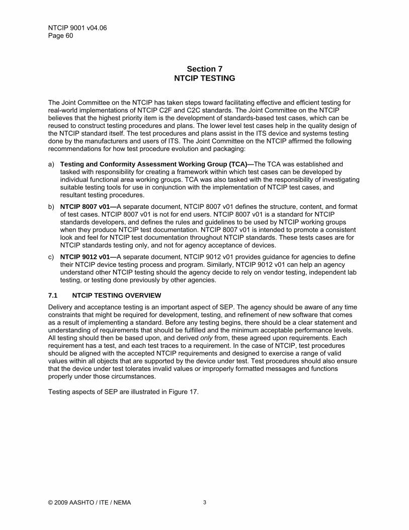
7.2 TESTING PHASES
An agency’s approach to testing for any deployment should consider the maturity of the ITS device, the number of units being acquired and installed, the agency’s ability to test, available expertise, and the relative significance of each agency specification requirement, among other factors. The approach to testing should be tempered with the number of units to be acquired, unique agency or project implementation requirements, and the history of the ITS device and NTCIP standards involved. Device testing is generally divided into the following phases:
a) Prototype test and inspection b) Design approval test and inspection c) Factory acceptance test d) Incoming device test e) Site acceptance test f) Burn-in and observation test
Table 10 summarizes the relationship of these testing phases with the testing phases defined by SEP.
4
NTCIP 9001 v04.06 Page 62
© 2009 AASHTO / ITE / NEMA
Table 10 NTCIP Testing Phases
Test Phase Purpose Number of Units Test Location Prototype Test and Inspection
Verify the electrical and mechanical design.
One prototype. Test Laboratory
Design Approval Test and Inspection
Verify the final design. Pre-production or a small percentage of the production units
Laboratory
Factory Acceptance Test
Verify production units are identical to the final design and production quality
A percentage of the production unit.
Production factory.
Incoming Device Test Inspect for damage due to shipping and handling.
All delivered units, including spares
Agency.
Site Acceptance Test Full functionality of the entire system.
All installed units. Final location for operation.
Burn-in and Observation Test
Monitor proper operation of the installed unit.
All installed units. Final location for operation.
7.3 TEST DOCUMENTATION
Test documentation is a key element of a testing program. Test documentation includes test plans, test cases and test procedures. Test documentation may be developed by the vendor, the agency, a test laboratory, a consultant, or perhaps it is based on test documentation used by another agency as part of their qualified products program. Testing is conducted by a combination of vendor, agency, and possibly an independent laboratory to verify that an ITS device complies with the agency specification. NTCIP 9012 v01 discusses the following test documentation:
a) Test Plan—Describes the scope, approach, resources, and schedule of testing activities b) Test Design—References the test cases applicable to a particular test plan associated with the
test design. The test design also references the features (requirements) to be tested. c) Test Cases and Procedures—Describes the inputs, outputs, expected results, and procedures
used to verify one or more requirements. d) Test Reports—Document the test plan execution.
Developing agency test documentation can take a significant amount of time and require coordination of many parties. It is recommended that test plan development begin after system interface requirements have been completed and approved. Test Design and development or Test Cases can begin after agency specification requirements have been approved and signed-off. Test Plan execution occurs throughout implementation, according to the suggested testing phases summarized in Figure 17. Test reports document test plan execution. Test documentation, as outlined, ensures that testing is thoroughly documented. In addition, test designs, test cases, and test procedures should be regularly reviewed based on past experience and results. NTCIP 9012 v01 identifies two standards that cover the test documentation needs for ITS device testing—IEEE 829 and NTCIP 8007 v01.
a) IEEE 829, IEEE Standard for Software Test Documentation—standardizes test documentation content and includes content descriptions for test plans, test design specifications, test case specifications, test procedure specifications, and test reports.
b) NTCIP 8007 v01, Testing and Conformity Assessment Documentation within NTCIP Standards Publications—focuses on system interfaces for C2F communications. NTCIP 8007 v01 does not include provisions for IEEE 829 test plans and test designs, and combines test case and test procedure aspects, which IEEE 829 maintains as separate.
5

NTCIP 9012 v01.27 Page 14
© 2008 AASHTO / ITE / NEMA
Section 4 TEST DOCUMENTATION
4.1 OVERVIEW
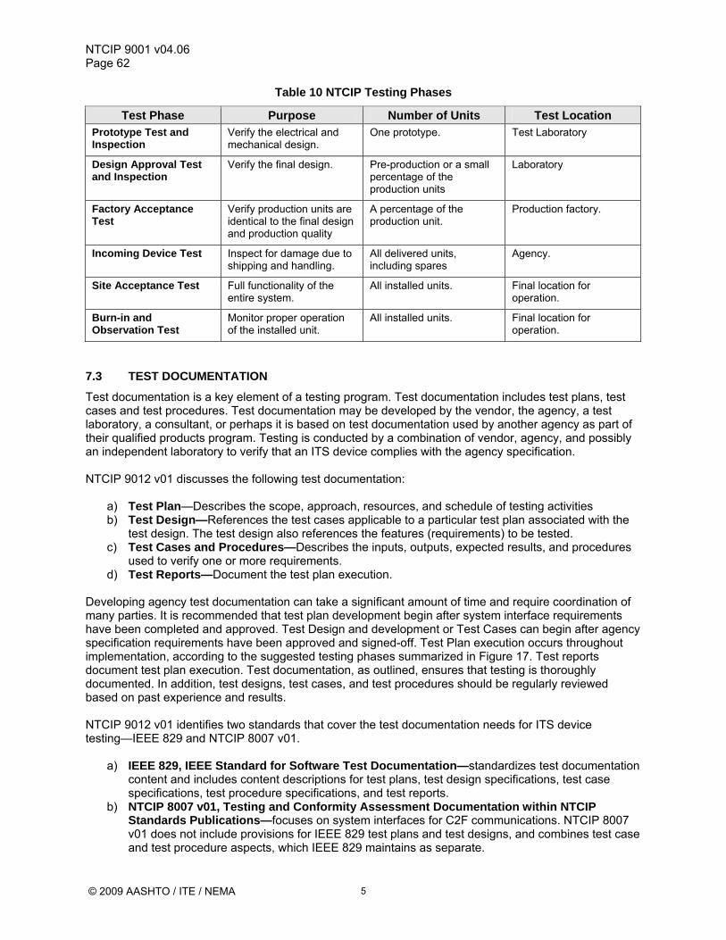
Figure 7 shows the relationship of key documents and relationships necessary to achieve complete and successful NTCIP testing. Section 4 reviews Figure 7, and explains each part, as well as key relationships between system documentation items. The concept in Figure 7, showing references from agency specification to standard, and agency test documentation to agency specification translates well to hardware and environmental testing. 4.1.1 ITS Device Standard
a) Standard Conformance Statement—Governs how conformance with the standard is fulfilled. The PRL supports conformance with the standard.
b) Standard Requirements—Are the standard’s functional requirements that the dialogs and object definitions fulfill. Generally, only a subset of the standard’s requirements are mandatory, the remainder being optional, or optional under certain conditions.
c) Dialogs and Object Definitions—Are the solution elements of the standard and fulfill the standard’s requirements.
d) PRL—Lists the mandatory, optional, and conditionally optional requirements.
e) RTM (Requirements Traceability Matrix)—Traces a requirement to the standards dialogs and object definitions.
4.1.2 Agency Specification
a) Reference to Standards—References the governing ITS standard for the agency’s specification.
b) Reference to Standards Conformance Statement—Addresses how the agency specification fulfills the standard’s conformance statement.
c) Agency Specification Compliance Statement—Governs how compliance with the agency specification is fulfilled. The PICS may support compliance with the agency specification.
d) Agency Specification Requirements—Are project- and agency-specific requirements, the results of tailoring of the standards, mandatory for the project. The PICS may support traceability to mandatory standards requirements and serve to support standards conformance.
e) Dialog and Object Definitions—Are project specific solution elements and fulfill agency requirements.
f) PICS (Profile Implementation Conformance Statement)—Is a tailored list of standards requirements that applies to the agency specification. The PICS reflects both a standard’s optional and mandatory requirements and when completed, reflects only those requirements included in the agency specification.
g) RTM—Traces an agency specification requirement to a standard’s dialogs and object definitions.
4.1.3 Agency Test Documentation
a) Reference to Agency Specification—Refers to the agency’s specification(s) for the test documentation.
b) Reference to Agency Specification Compliance Statement—Addresses how the test documentation fulfills the specification compliance.
6
G-Thomas
Text Box
Extracted from NTCIP 9012

NTCIP 9012 v01.27 Page 15
© 2008 AASHTO / ITE / NEMA
Figure 7 NTCIP Test Documentation
c) Test Plan—Describes the scope, approach, resources, and schedule of testing activities.
d) Test Design—References the test cases applicable to a particular test plan associated with the test design. The test design also references the features (requirements) to be tested.
e) Test Cases and Procedures—Describe the inputs, outputs, expected results, and procedures used to verify one or more requirements.
f) RTCTM (The Requirements to Test Case Traceability Matrix)—Traces an agency specification requirement to test cases. The RTCTM can be used to ensure that at least one test case covers each requirement.
Developing agency test documentation can take a significant amount of time and require coordination of many parties. It is recommended that test plan development begin after system interface requirements have been completed and approved. Test design development can begin after agency specification requirements have been approved and signed-off while test case development can begin after the agency’s specifications have been approved and signed-off. Test procedure development can begin after the design has been approved. Test plan execution occurs throughout implementation, according to the suggested testing phases described in the SEP summarized in Figure 3. Test reports document test plan execution.
NTCIP Device Standard
Agency Specification
Agency Test Documentation
Conformance Statement
Standard Requirements
Dialogs & Object Definitions
PRL—Identifies Mandatoryand Optional Requirements
RTM—Traces Requirementsto Dialogs and ObjectDefinitions
Reference to Standards
Agency Specification Requirements
Dialogs & Object Definitions
PICS—List of Standard Requirements that are Specification Requirements
RTM—Traces Specification Requirements to Dialogs and Object Definitions
Agency SpecificationCompliance Statement
Reference to Standards Conformance Statement
Reference to Specification
Test Design—Based on IEEE 829-1998
Test Cases & Procedures—Based on NTCIP 8007 v01
RTCTM—TracesSpecification Requirementsto Test Cases
Test Plan—Based on IEEE 829-1998
Reference to Specification Compliance
The PRL spells out what requirements are necessary for standards conformance
The PICS is a tool to ensure that a specification contains all requirements necessary for standards conformance.
The RTCTM is a tool to ensure that each agency specification requirement is covered by at least one test case.
<NTCIP 9012 Fig7 bs3.ppt>
7

NTCIP 9012 v01.27 Page 16
© 2008 AASHTO / ITE / NEMA
4.1.4 Test Documentation Standards
In the context of NTCIP 9012 v01, two standards cover the test documentation needs for ITS device testing—IEEE 829-1998 and NTCIP 8007 v01. a) IEEE 829-1998—Standardizes test documentation content. IEEE 829 includes content descriptions
for test plans, test design specifications, test case specifications, test procedure specifications, and test reports.
b) NTCIP 8007 v01—Is an IEEE 829-1998-based standard that focuses on system interfaces for center-to-field communications. NTCIP 8007 v01 does not include provisions for IEEE 829-1998 test plans and test designs; however, NTCIP 8007 v01 combines test case and test procedure aspects, which IEEE 829-1998 maintains as separate.
4.2 IEEE 829-1998 TEST PLAN
With any standard or specification, discussion eventually turns to the question "how do we know if an implementation or application conforms with the standard and complies with my specification?" A test plan defines how one answers this question. As defined in IEEE 829-1998, a test plan describes the scope, approach, resources, and schedule of testing activities. It identifies the items to be tested, the features to be tested, the testing tasks to be performed, the personnel responsible for each task, and the risks associated with the test plan. The details of a test plan should be fully developed before an ITS device is delivered. IEEE 829-1998 provides a template for the content of a test plan, and includes: a) Test Plan Identifier b) Introduction c) Test Items d) Features to be tested e) Features not to be tested f) Approach g) Item Pass/Fail Criteria h) Suspension Criteria and Resumption i) Test Deliverables j) Testing Tasks k) Environmental Needs l) Responsibilities m) Schedule n) Risk and Contingencies o) Approvals The following subsections group and discuss the 15 items comprising an IEEE 829-1998 Test Plan. 4.2.1 Test Plan Identifier and Introduction
4.2.1.1 Test Plan Identifier
Each test plan requires a unique identifier, as several test plans may be needed to address a comprehensive testing program for ITS devices. 4.2.1.2 Introduction
The introduction section should describe how a particular test plan fits within the broader testing program, and reference all relevant documents, for example the communications interface requirements, agency specification requirements, and design.
8

NTCIP 9012 v01.27 Page 17
© 2008 AASHTO / ITE / NEMA
4.2.2 Test Items and Item Pass/Fail Criteria
4.2.2.1 Test Item(s)
This is a description of the item, defined by requirements, to be tested. This may include software, communications interface, or hardware and environmental requirements. The ITS device communications interface test item tests compliance with a specification and/or standards conformance. The standards conformance aspect may simply be an identification of which specification requirements are also mandatory by the standard, so that testing of a requirement that fulfills the requirements of the standard and the specification need only be done once. A second (and separate) device communications interface test item may be the ITS device functions (observable behavior) that accompany any particular dialog or sequence of data exchanges. Other test items (for which there should be associated requirements) may include ITS device hardware and environmental testing. 4.2.2.2 Item Pass/Fail Criteria
Item Pass/Fail criteria are used to determine whether each test item has passed or failed a test case or procedure. 4.2.3 Features to be Tested and Features not to be Tested
4.2.3.1 Features to be Tested
The features to be tested are the agency specification requirements associated with their respective test procedure or test case. 4.2.3.2 Features not to be Tested
A test plan should also identify features not to be tested (for example, those standard requirements that are optional or those PICS elements not required in the agency specification). Another example is the case where certain testing would unduly stress the limits of a prototype thus preventing further testing of a scarce resource—the prototype. 4.2.4 Approach, Risks and Contingencies
4.2.4.1 Approach
The test plan developed by the agency should address the types of testing that are to be conducted to verify that delivered ITS devices comply with agency specification requirements. Testing phases may include: a) Prototype test and inspection b) Design approval test and inspection c) Factory acceptance test d) Incoming ITS device test e) Site acceptance test f) Burn-in and observation test The approach should identify the test procedures and test cases that are scheduled during each test phase. See Section 5.2.
9

NTCIP 9012 v01.27 Page 18
© 2008 AASHTO / ITE / NEMA
4.2.4.2 Risks and Contingencies
This section of the test plan identifies the significant risks that may result from testing and associated contingency plans. This includes prospective risks to schedule, related funding impacts, and a process to address the situation if it occurs. 4.2.5 Suspension Criteria and Resumption
This section of the test plan covers test start-up, re-start, and regression testing. Even if an ITS device has a proven track record, software enhancements or changes to support additional functionality can seriously corrupt the overall performance and conformance of the ITS device. ANY software changes made by the manufacturer may be considered sufficient reason to repeat the full battery of associated NTCIP testing and performance measurements. A test plan applies to a specific combination of hardware, firmware, MIB and version of standard. A change in any of these components has the potential to invalidate any previous conformance testing and should trigger a regression test of all completed conformance testing. When the hardware platform is changed, the working firmware may frequently be modified to work on the new hardware platform even if the firmware retains the same version designation. Depending on the new hardware platform some subtle problems can arise, i.e. byte ordering for messages, calculation of the frame check sequence, or simply the correction of perceived errors. Even if the hardware platform is maintained, a change in the firmware triggers regression testing for a variety of reasons. Depending on the manufacturer’s code management practices problems that had been resolved can be introduced back into the firmware because a developer was working with an older version of the firmware. A change in the MIB or the version of the standard used for the ITS device always triggers a regression test. The MIB describes all data that is accessible from the external interface; a change in the MIB has many possible ramifications. The standard describes how the ITS device interface is to function. A change to the standard implies that some functionality has changed either via addition, deletion or method of operation. An example of this change is NTCIP 1201. The original NTCIP 1201:1996 defined a specific methodology for creating dynamic objects. After NTCIP1201:1996 was released, an error was discovered in the methodology and an amendment was released in 1998. The amended NTCIP 1201:1996 methodology for creating dynamic objects is incompatible with the original NTCIP 1201:1996 methodology. Therefore, an ITS device that conforms to the original NTCIP 1201:1996 fails conformance testing against the amended NTCIP 1201:1996 standard. 4.2.6 Test Tasks, Test Deliverables, and Schedule
4.2.6.1 Test Tasks
This section of the test plan lists all the tasks necessary to prepare and conduct the testing. This section may include a table of test tasks, listing the following: task identifier, task name, predecessor tasks, responsibility, and special skills required. 4.2.6.2 Test Deliverables
The test deliverables is a list of all the test documentation, the development and writing of which is necessary for the test, including reports on the performance of the ITS device during the tests. 4.2.6.3 Schedule
The schedule is a list of milestones, and when all resources and people are needed. The test tasks included in the approach section of the test plan may serve as a starting point, with start and stop dates and times added.
10

NTCIP 9012 v01.27 Page 19
© 2008 AASHTO / ITE / NEMA
4.2.7 Environmental Needs
This section of the test plan describes the configuration, necessary hardware, software, testing tools, supplies, lab facilities, centers, and reference documentation for testing. It is often useful to include a diagram showing the set up for testing: locations and positioning of equipment, people, tables, chairs, and projection systems (so that everyone participating in the testing can see what is happening). Also include a list of equipment, equipment description, and equipment purpose to accompany the diagram. This section of the test plan should also address the management of hardware and firmware configurations. The growing role of software in most ITS devices, and the speed with which the software can be changed, increases the need for careful management of the hardware and firmware configuration that has been subjected to testing. Not only should the configuration be managed but the subject of regression testing takes on a new significance. Current testing programs of ITS devices have frequently found that new firmware for an ITS device, designed to fix some problems, may unintentionally either (a) introduce new problems that were not present before, or (b) bring back problems that had been corrected. The issues with testing and overall ITS device compliance can only be corrected with the definition and execution of effective testing and careful configuration management to assure that what is delivered is what is tested. Validating the test environment assures that errors and anomalies are detected and corrected before testing begins. The test environment includes: a) all instrumentation to measure and monitor the performance of the ITS device;
b) all environmental test equipment such as temperature and humidity chambers;
c) all input simulation devices where required such as loop simulators or sample data streams; and
d) power line management including transient generators, variacs, and power interrupters.
The test procedure should include a section where the test environment is validated by simulating or stimulating each error that could result from errors inherent in the test environment. The test procedures should be based on the resources and facilities readily available to them. Environmental test procedures that are currently included in standards, such as NEMA TS 2-2003 and the CalTrans TEES outline elements of the testing process. These testing processes may guide the development of appropriate test plans to demonstrate compliance of the ITS device with the agency specifications. The test plan should completely describe the test installation, all connections, all instrumentation, and exactly what and how the units are to be monitored. 4.2.8 Responsibilities and Approvals
4.2.8.1 Responsibilities
The responsibilities section of the test plan identifies the groups and/or individuals responsible for managing, designing, preparing, executing, witnessing, checking, controlling the environment in the laboratory, getting equipment and supplies, setting up equipment and software, report writing, and approving (who signs the approval sheet) [Kaner, C., Testing Computer Software, 1999, p. 248]. Who conducts testing is addressed in Section 5.3. 4.2.8.2 Approvals
Some agencies require that an officer of the corporation approve test results. It is recommended that the agency or a trusted independent agent witness and approve all testing.
11

NTCIP 9012 v01.27 Page 20
© 2008 AASHTO / ITE / NEMA
4.3 IEEE 829-1998 TEST DESIGN
A test design is generally associated with one test plan. The test design identifies which test cases are used to verify which agency specification requirements. This allows the re-use of test cases and test procedures. A test design refines the test approach and identifies the requirements to be addressed by the test plan and its associated tests. It also identifies: agency specification requirements, test cases, and test procedures used to accomplish testing, and specifies the pass/fail criteria for each test item. See IEEE 829-1998. 4.4 NTCIP 8007 V01 TEST CASES AND TEST PROCEDURES
4.4.1 Test Case and Procedures Overview
Given the sophistication of today’s systems and components, it is impossible to test all possible combinations and permutations of how a system or component might react. In general, the principle is to define at least one test procedure for each agency specification requirement and then exercise those features in the context of how they should react in a normal system operation environment. Another way to think about this is to consider whether every ITS device procured is tested completely or whether a representative sample is sufficient. For example, is it necessary to test every parameter to see if it can be set to every possible value? Not necessarily. A sample set of values probably suffices for a representative set of parameters. One has to consider the risk involved. If one parameter of some type accepts the minimum, maximum, and several values in between and rejects several invalid values, chances are that all parameters react the same way. Likewise, ITS device testing should include some measure of negative testing, i.e. the device under test (DUT) should be subjected to normally occurring anomalies such as power failures, disruption of communications channels, overloaded communications channels (worst case traffic) and such input anomalies as intermittent connections. In most cases, the DUT is expected to recover without intervention and return to normal operation without creating unsafe conditions prior to, during, or after the disruption. Test procedures and test cases should cover the agency specification requirements to be tested and be fully developed before an ITS device is delivered. While a certain amount of randomness can be added to any well-defined procedure or test case, the specific approach should be spelled out. NTCIP 8007 v01 provides examples of how test procedures and test cases should be defined. As test procedures and test cases are added to NTCIP standards, the need to develop separate, independent test procedures to evaluate NTCIP conformance diminishes. The test procedure should include a listing of all commands that are to be sent to the unit and all expected responses, as well as timing tolerances for all actions. The test procedure should also include inspections and design reviews for those portions of the agency specification requirements that are not verified by operational testing. These typically include design requirements for electronic components (voltage and thermal margins) and materials as well as construction techniques. A requirements matrix, which puts in table form each agency specification requirement—with additional tables for the requirements for the standards conformance—should be developed. Then, for each requirement, the table should identify a test case or type of measurement or inspection that is to be made to verify compliance with the agency specification requirement. The test procedure should be written with some flexibility so that a suspected anomaly can be verified (re-tested) as the test progresses. It is also important to note that any anomaly – no matter how slight, should be documented. If the anomaly is “improper operation”, then the cause and cure should be determined and documented. For example, if an anomaly appears once in 10 testing attempts, the total number of occurrences, when 100 units are installed, is likely to be much higher. Often, moving ahead with testing (after the anomaly seems to disappear) is suggested, while awaiting more detailed findings regarding the anomaly observed. While this approach typically has value because testing proceeds, and it is possible to
12

NTCIP 9012 v01.27 Page 21
© 2008 AASHTO / ITE / NEMA
evaluate whether the DUT is likely to meet all other agency specification requirements, there is a risk that the correction introduced to fix the anomaly may necessitate complete re-testing. This is a judgment call with risks and benefits for all parties involved with the testing. It is important to determine the root cause and cure for any anomaly, or intermittent problems may surface during subsequent testing or after installation of the ITS device in the field. 4.4.2 Boundary and Error Condition Tests
Testing should include verification that invalid data communications does not cause the ITS device to operate in an abnormal manner. Invalid data communications can include any of the following: a) A noisy communications link
b) A chattering modem
c) Improperly formatted data
d) Properly formatted data that does not meet the ITS device’s consistency checks
e) Interrupted and restored communications
In addition to continuing to operate when invalid data is impinging on the ITS device’s communication port, the ITS device should co-exist with others on the same channel and not be adversely impacted. During ITS device testing in some deployments, the following extreme test outcomes have been observed: a) ITS device clock drift while interpreting NTCIP messages destined for a different ITS device;
b) ITS device “crashes” while attempting to read data from a noisy communications line; and
c) Inability of the ITS device to manage its field functions while processing NTCIP messages
This section of the test plan ensures that the ITS device (or system) performs the required functions when exposed to the proper data elements (parameters) in the proper sequence (dialogs) and does not perform improperly when subjected to bad data or the wrong sequence of data elements and messages. This aspect of testing should be tempered with reasonable risk assessment as not all possible conditions can be tested. These conditions should include those situations that are likely to exist under extreme situations. 4.4.3 Test Case and Procedures Documentation
A format for developing test procedures is included in NTCIP 8007 v01. The test procedure should reference the agency specification requirements, and those requirements contained in the NTCIP standard. The agency specification should include the operational, maintenance, and performance requirements to be tested, define the dialogs that satisfy the agency specification requirements, and trace to the appropriate objects (from the NTCIP standards). The test procedure should identify a test case for each of the agency specification requirements or in some cases, each NTCIP data object. Using this as background, the test procedure should exercise each of the data parameters (objects) and require specific observations based on the agency specification requirements. Many test cases are complex and require very complex testing setup to verify a single requirement (e.g. Daylight Savings Time transition). NTCIP 8007 v01 organizes test cases and includes the following elements: a) Test Case Identifier—A unique test case identifier.
b) Test Case Title—A unique title for the test case. This title is to be used in the trace matrix.
13

NTCIP 9012 v01.27 Page 22
© 2008 AASHTO / ITE / NEMA
c) Description—Describes the test and purpose of the test case.
d) Test Items—These identify the agency specification requirements being tested. Mapping of requirements to test cases is documented in the RTCTM.
e) Input Specification—A description of data values and tolerances for each data concept requirement. If the information is kept in a file, then this may be the file name. The input specification also includes a way to indicate whether data values are valid. This is the criteria for pass/fail.
f) Output Specification—A description of data values and tolerances for each data concept requirement. If the information may be logged to a file for subsequent verification and analysis of format and data value ranges. The output specification also includes a way to indicate whether data values are valid. This is the criteria for pass/fail.
g) Environmental Needs (Optional)—In cases where the environmental needs are different (or require additional resources from what is described in the test plan or test design specification), then this section should be included.
h) Special Procedural Requirements (Optional)—In cases where special procedures for startup, setup, wrap up, etc. differ, then this section should be included, as applicable.
i) Dependencies—This lists the dependencies for this test case. It allows an ordering of test case execution to be developed.
j) Procedure Steps—This lists steps and step number.
k) Test Log—A record of relevant details about the execution of a test. Test log information should note procedure step.
4.5 TEST EXECUTION REPORTS
This section briefly summarizes the test reports outlined in IEEE 829-1998 and NTCIP 8007 v01, where additional detail is provided. a) Test Log—The test log is a chronological record of the execution of the test including persons
present and roles, procedure results, and any anomalies encountered.
b) Test Incident Report—This report documents any event that occurs during testing that required further investigation. It records expected versus actual results, procedure and procedure step, and attempts to repeat the test. It should also record potential impacts on further testing activities.
c) Test Summary Report—This report summarizes the test plan executions.
4.6 SAMPLE TEST DOCUMENTATION LINKS
Example test procedures from several agencies are available on the Internet. The referenced test procedures demonstrate the amount of effort that is required to properly test ITS devices incorporating NTCIP standards. These example test procedures are the result of multiple iterations of testing. The example test procedures include: a) NTCIP test procedures developed for the “ENTERPRISE” pool fund project and are available at
http://www.trevilon.com/library.html.
b) Actuated signal controller test procedures that Texas Transportation Institute developed can be found at http://www.itstestlab.org/ by clicking on testing and then on In House Testing and Scripts. The files under the procedure column are in NTCIP 8007 v01 format.
c) Florida Department of Transportation (FDOT) Florida State University (FSU) Traffic Engineering Research Lab (TERL) has been developing NTCIP test procedures to qualify Dynamic Message signs for use in the state. Information on their test procedures and results can be found at: http://potentia.eng.fsu.edu/terl/areas_of_work_ntcip_testing.htm.
14

NTCIP 9012 v01.27 Page 23
© 2008 AASHTO / ITE / NEMA
d) Additional test procedures are likely to become available as more and more agencies adopt NTCIP for their center to field protocols.
4.7 SUMMARY
A significant level of expertise in the ITS device and agency specification requirements is needed to develop test documentation. Significant resources in terms of facilities and personnel, are needed to implement a comprehensive testing program, and the use of independent testing laboratories, or reliance on test results from other sources such as other states may be warranted. While this approach can be successful, the agency should examine the test plans, specification requirements, and test results to verify that the results of the testing are applicable to an agency’s unique implementation and related testing program. Where there are differences, the agency should evaluate risk associated with accepting previous results against the benefit of establishing a new testing program.
15

NTCIP 9012 v01.27 Page 24
© 2008 AASHTO / ITE / NEMA
Section 5 TEST EXECUTION
5.1 OVERVIEW
A complete ITS device testing program consists of many phases of testing, taking place in a methodical approach. Overall, the testing program should cover all requirements leading to a complete ITS device design including electrical requirements, mechanical requirements, operational requirements, communications requirements, and design requirements (such as voltage and thermal operating margins for electronic components). Each phase may be described in its own test plan covering a set of test items: one for hardware and environmental requirements (e.g., structural, mechanical, electrical or environmental), one for software-related requirements (e.g., functional, operational), and one for communications requirements (e.g., communications interfaces). An agency’s approach to testing for any deployment depends on the maturity of the ITS device, the number of units being acquired and installed, the agency’s ability to test, available expertise, and the relative significance of each agency specification requirement, among other factors. 5.2 ITS DEVICE TESTING PHASES
The approach to testing should be tempered with the number of units to be acquired, the degree of tailoring of the ITS standards to accommodate unique agency or project implementations, and the history of the ITS device and standards involved. ITS device testing is generally divided into the following phases: a) Prototype test and inspection b) Design approval test and inspection c) Factory acceptance test d) Incoming ITS device test e) Site acceptance test f) Burn-in and observation test Figure 8 summarizes the relationship of these ITS device testing phases with the testing phases defined by the SEP. Figure 9 summarizes key attributes of these ITS device test phases.
SystemVerification &
Deployment
SubsystemVerification
Unit / DeviceTesting
3. Factory Acceptance Test2. Design Approval Test1. Prototype Test
Test Execution
5. Site Acceptance Test4. Incoming Device Test
6. Burn-in and Observation Test
SystemVerification &
Deployment
SubsystemVerification
Unit / DeviceTesting
3. Factory Acceptance Test2. Design Approval Test1. Prototype Test
Test Execution
5. Site Acceptance Test4. Incoming Device Test
6. Burn-in and Observation Test
Figure 8 Relationship of Test Execution Phases to the VEE Model
A Testing Program: • Should include ALL
requirements • May be separated into
test plans, each testing a TYPE of requirement
• Should be performed in phases
16

NTCIP 9012 v01.27 Page 25
© 2008 AASHTO / ITE / NEMA
Test Phase Purpose Number of Units Test Location
Prototype Test and Inspection
Verify the electrical and mechanical design.
One prototype. Test Laboratory
Design Approval Test and Inspection
Verify the final design. Pre-production or a small percentage of the production units
Laboratory
Factory Acceptance Test
Verify production units are identical to the final design and production quality
A percentage of the production unit.
Production factory.
Incoming ITS device Test
Inspect for damage due to shipping and handling.
All delivered units, including spares
Agency.
Site Acceptance Test Full functionality of the entire system.
All installed units. Final location for operation.
Burn-in and Observation Test
Monitor proper operation of the installed unit.
All installed units. Final location for operation.
Figure 9 ITS Device Testing Phases
A brief description of each phase follows. 5.2.1 Prototype Test and Inspection
The purpose of the prototype test is to verify the electrical and mechanical design of the ITS device for the environmental conditions of the specifications. If the ITS device is a custom development or custom extension to an existing ITS device designed to meet a unique agency specification requirement with a number of unique physical and electrical requirements, then it may be necessary to identify a prototype testing phase for the ITS device. During the prototype testing phase, the ITS device manufacturer constructs a fully operational version of the ITS device for inspection and testing by the agency. Testing may follow a hardware testing profile, such as NEMA TS 2 or CalTrans TEES, and is performed by the manufacturer, an independent laboratory, or the agency itself. Testing, at a minimum, should include environmental testing (temperature and humidity) and electrical testing (voltage variation, interruptions, and transients), although the testing apparatus and instrumentation required to conduct a rigorous NEMA testing program requires expertise in the electrical and electronic aspects of testing. Prototype testing also verifies the functionality (e.g. actuated operation, ramp control) and performance requirements (e.g. timing accuracy, transmission times, startup times, communications timing). One aspect of testing that is often postponed until the final production version of the ITS device is shock and vibration testing depending on the completeness of the mechanical design. NTCIP testing (communications, functionality, and performance) is usually a part of the prototype test. It is important that such a prototype testing program include inspections to verify that the DUT truly complies with all of the requirements of the agency specification requirements and those auxiliary standards typically referenced including NEMA, New York State, CalTrans, and Military standards as examples. Agency specification requirements should define appropriate testing for any custom or semi-custom ITS device that is electrically and mechanically different from ITS devices previously tested. Changes to the electrical design and components may have significant effects on compliance. Testing on a previous version of an ITS device may provide some indication of the performance of the new design. However, a repeat of previous testing may be warranted as even minor changes can have an impact, and any electrical or electronic changes typically warrant a repeat of previous environmental testing. Agency specifications may also include additional provisions such as more extensive power interruptions and slowly varying AC line voltages that are further defined beyond what is required by a referenced standard. As an example, NEMA TS 2 does not require that a traffic signal controller be subjected to transient voltages at low temperatures. If transient voltages under these conditions have been of concern,
17

NTCIP 9012 v01.27 Page 26
© 2008 AASHTO / ITE / NEMA
an agency may wish to include test items for traffic signal controllers using transient voltages during low temperature operation, if transient voltages under these temperature conditions have been an issue previously. Even when an ITS device is “standard,” and has been used before or is already on another agency’s qualified products list (QPL), the procuring agency should perform a design review to ensure that the ITS device complies with the agency’s specification requirements. This review should include an examination of the details of the testing and inspection program used to accept the ITS device on the QPL to ensure that the ITS device is, in fact, the same product that was previously tested. ITS device functional testing should also include the ability to manage failures, detect failures, and report failures where these requirements are identified (in either the agency specification or referenced standards). For large devices such as dynamic message signs, a sample unit may be constructed consisting of a few panels, sample control electronics, etc. This is generally sufficient to evaluate the performance and operation of the ITS device, as long as it is subjected to worst case loading and maximum processing loads. Such a sample unit should be large enough to fully stress the power supplies and controller operation or test results may not be representative of the final unit performance. Under these circumstances, the agency should work with the manufacturer to ensure that the sample unit tested is representative of a worst-case deployment of the ITS device. 5.2.2 Design Approval Test
The second phase of ITS device testing occurs when the ITS device is in its final production form. This is generally considered the Design Approval Testing (DAT) and includes a repeat of the prototype testing and inspection along with the shock and vibration testing. DAT verifies that the ITS device in its production form fully complies with all of the standards (conformance) and agency specifications (compliance). At this point, the documentation for the ITS device should also be included in the inspection. DAT is typically performed on a group of pre-production (or production) units randomly selected from the first production run. It is generally recommended that a minimum of five units be simultaneously tested, although when procuring a small number of large ITS devices (e.g. DMS) this may be impractical. NTCIP testing should be part of the DAT program; it is beyond the scope of NTCIP 9012 v01 to provide guidance in managing DAT beyond NTCIP testing. It is recommended that shock and vibration testing be performed prior to the performance and environmental testing. This ensures that any latent failures (e.g. partially fractured connections) are more likely to become visible during the more extensive environmental testing. Several issues are important when reviewing the proposed prototype testing; first, exactly what is monitored and how. It is important that the test environment be thoroughly inspected and tested to see that if errors do occur, they are detected. Further, all monitoring should be continuous, since some failures can be transient in nature and caused by thermal gradients within the ITS device. The instrumentation used to measure the operation of the ITS device or the test environment (temperature, voltage, etc.) should be calibrated – and the calibration should be recent. The calibration should be performed based on the instrumentation manufacturer’s guidelines and depends on the type of instrumentation and usage. Second, it is important to fully define what constitutes proper and improper operation. This should be clearly identified within the test procedure. A word of caution; many ITS devices can be very complex in nature and there may be occasions when an “anomaly” occurs during which the DUT does not function properly, e.g. it may have reset and recovered, and a repeat of the same test step seemed to clear the failure. Other examples might include pixel failure
18

NTCIP 9012 v01.27 Page 27
© 2008 AASHTO / ITE / NEMA
reports that seem to disappear or measurements that seem to have a transient error when read. Such occurrences are suspect and should cause the test to be classified as “failed” requiring a detailed analysis of the cause and cure for the anomaly. There is a tendency to “pass” a DUT with such a transient failure, but if such an anomaly was experienced in a small sample of ITS devices, additional anomalies may be anticipated in a larger number of ITS devices when deployed. As an example, if the DUT experiences an unexplained anomaly that requires manual intervention (e.g., reset, power cycling) during the test (for no apparent reason), when many units are installed, it may be anticipated that a larger number of deployed ITS devices may exhibit similar anomalies, each necessitating manual intervention. Both prototype testing and DAT should be witnessed by the agency or an independent, knowledgeable third party. Agency participation has several advantages, including: a) the agency is the best judge of the many issues such as ease of repair or accessibility,
b) the agency has the opportunity to observe the device under extreme conditions, and
c) should the ITS device experience an anomaly or failure, the agency gains some experience and understanding of what to expect when ITS device failures occur after installation.
5.2.3 Factory Acceptance Test
This is usually the final test performed prior to delivery of the ITS devices to the agency and may be observed by the agency. The purpose of this testing is to ensure that production units have been constructed in a manner identical to the unit that was subjected to the DAT and that all connections and functions are fully operational. Where the ITS device includes analog functions, these need to be verified to ensure that the operation is within acceptable tolerances. For larger ITS devices, such as DMS, this typically includes such aspects as detailed inspection of the construction, review of such requirements as the power consumption and the weight of the unit, and verification that all pixels are operational and of uniform intensity. In general, the factory acceptance test (FAT) includes a 100% continuity and function verification to make sure it has been constructed without errors. If the ITS device being offered is “standard,” and the ITS device has undergone previous prototype and DAT, then the detailed design review and environmental testing is often waived. This means that the FAT is the only opportunity the agency may have to review the ITS device prior to shipment. Some agencies (e.g. CalTrans) require that all units undergo a monitored burn-in and environmental cycle over either the full or a limited range of the anticipated ambient temperatures for the installation. This type of burn-in is recommended for electronic ITS devices and is typically on the order of 100 hours. While the entire DMS cannot be temperature tested, portions of the ITS device such as the controller could be subjected to the environmental cycling. The FAT should include inspection for construction such as conformal coating and water leakage testing. 5.2.4 Incoming ITS device Test
Once the ITS device is delivered to the agency, it should be inspected for damage due to shipping and handling. Where possible, the ITS device should be powered and run through a test that fully exercises all of the connections, features, and functions. Some agencies have established testing labs and/or integration test facilities. Where such a facility is available, the incoming ITS device testing can be more rigorous and involves portions of the site acceptance testing. This approach is often taken when the agency plans a large-scale upgrade program. Such an integration testing facility allows the agency to fully configure and test the ITS device under simulated conditions (loops, communications, signal heads) and verify the end-to-end operation.
19

NTCIP 9012 v01.27 Page 28
© 2008 AASHTO / ITE / NEMA
Where the central system is not available, this becomes a unit test of the ITS device where all of its operations can be verified using a stand-alone simulator or other test unit and all inputs can be simulated. 5.2.5 Site Acceptance Test
Once the ITS device has been installed at its intended location for operation, the full ITS device functionality is again tested and verified. If the system is in place, this means connecting the ITS device to the complete system and verifying all of the operation and feedback of the ITS device. Where the central system or the communications infrastructure may not be available, this testing should be performed with a stand-alone central simulator or similar tester. Once the ITS device has been tested and verified (e.g. CCTV images are within tolerance, pan-tilt-zoom functions work properly, sign messages display properly, all pixels function correctly and that failure detection logic is working properly), the ITS device is accepted subject to a period of observation and operation. A word of caution on installing ITS devices such as CCTV cameras and dynamic message signs before the communications systems are in place. Once the ITS device is installed at its final location and the site acceptance test has been completed, it is recommended that the ITS device be energized and monitored. It is generally not recommended that the ITS device be installed and remain un-powered and unused for a prolonged period of time. 5.2.6 Burn-in and Observation Test
Once the ITS device is installed and verified, it is connected to the system and undergoes a period of observation; this is typically a period of 30-60 days during which the ITS device should exhibit fault free operation. During this period of time, the ITS device should be exercised to monitor the functionality of the unit. This may include test messages, operator usage of a camera, operation of the traffic signal, or data collection as examples. It is important for this phase of the testing that the ITS device be exercised and inspected regularly, that failures are detectable, that the ITS device is continuously monitored, and that failures of the communications infrastructure or the central system are not attributed to the ITS device itself. Where ITS device acquisition is independent of the communications infrastructure and the central system, it is important that acquisition provisions identify the responsibilities of the ITS device manufacturer in a manner that can be measured and ongoing resource allocation purposes. It is also important that the ITS devices and the system be subjected to full communications loading to ensure that there are no latent processing problems due to the amount of network traffic. Recent experiences with some ITS devices in an Ethernet environment have revealed processing deficiencies that have caused ITS devices to gain/lose time, go into flash, or experience other timing anomalies. Hopefully these types of problems have been anticipated and were included in the DAT. 5.3 WHO SHOULD PERFORM TESTING
With any ITS device testing, the agency should identify the party that conducts the testing, as well as appropriate performance provisions and a clear understanding of the responsibilities of all parties involved with testing. The agency should also include a clear description of the consequences of test failure in terms of procurement, budget constraints, and schedule. 5.3.1 Agency Testing
Agency testing is that component of the testing framework that is carried out by members of the agency’s staff. It is expected that the agency, possibly with an outside consultant, possesses the technical knowledge, the tools and the staff to conduct this phase of testing, independent of manufacturer assistance. Frequently this is the last stage of testing for the project when the agency is making the final determination that the delivered system complies with the agency specifications. To insure comprehensive testing of an ITS device, an agency should be involved in the creation of the requirements and test documentation used to verify whether or not the ITS device complies with the
20

NTCIP 9012 v01.27 Page 29
© 2008 AASHTO / ITE / NEMA
agency specification. The agency should also develop an understanding of the referenced standards to accurately evaluate the results of the testing. Agency personnel should also witness testing to provide verification of the proper execution of test plans. 5.3.2 Manufacturer Testing
Manufacturer testing covers those tests that are conducted by the manufacturer. Procurement of a field-proven, off-the-shelf ITS device may not necessitate additional manufacturer testing. If an ITS device is being developed specifically for the agency, or an existing ITS device is being modified for the agency, then additional tests should be required. The agency, or its consultant representative, should witness such additional manufacturer tests. The issue of hardware/firmware configuration management is particularly important for manufacturer testing. The manufacturer should be able to positively identify both the hardware revision and firmware revision that has been (or is being) tested. The firmware version number should provide the agency with sufficient information that the specific firmware build can be tracked, including all test versions. Although manufacturer testing is typically required it is not sufficient by itself. The drawback to manufacturer testing is the lack of the unique installed environment in which the ITS device is expected to function in the field. The environment includes the central system, the communications infrastructure and the presence of other ITS devices or components that are functioning together with the ITS device (i.e. peripherals or devices which share the same communications channel). If a project specifies that an ITS device should extract information from another ITS device and send that data to the central system the second ITS device should be available to adequately test the function. Manufacturers should submit a complete description of their test approach, test environment, and explain and demonstrate how the test configuration measures the parameters and detect errors when they should occur. 5.3.3 Independent Laboratory Testing
Independent laboratory testing is often used to verify that an ITS device meets certain environmental specifications such as vibration, temperature ranges, power conditions, and light output. Such testing is commonly required for traffic controllers and other ITS devices. A testing outline is contained in such documents as the NEMA TS 2-2003 standards for traffic signal controllers and previous versions of the NEMA Standards (e.g. NEMA TS-1-1989), the CalTrans TEES, and NEMA TS 4-2004. However, such standards do not document all of the unique agency or project test procedures, test configuration, and equipment operation to be monitored. Such test procedures are often developed by the manufacturer or the agency and provided to the testing laboratory that monitors the testing and provides the measurement and monitoring equipment. When an independent laboratory is used for NTCIP testing, the agency should first define the test procedures and test cases the independent laboratory is using. For example, the agency should determine whether the laboratory is testing communication with the ITS device or the function of the ITS device. In either case the agency should work with the laboratory to define the entire test methodology. If the testing laboratory is unfamiliar with the ITS device or the standards, then the agency (or consultant) should provide guidance in the form of a test plan which includes the test configuration and test procedures. An independent laboratory may not have domain expertise. Even when a detailed agency specification requirements and associated PRL are provided, there is significant opportunity for errors in testing based on lack of domain expertise. Database download, for example, is an area that requires significant domain expertise. For instance, if a download of the Phase Block Data as specified in NTCIP 1202 v2 is rejected, domain expertise determines where the test procedure, the test environment or the ITS device failed. Depending on the data supplied for some of the elements of the data block a rejected download is the correct action by the controller.
21

NTCIP 9012 v01.27 Page 30
© 2008 AASHTO / ITE / NEMA
And finally, the independent laboratory does not necessarily have access to the assets necessary to conduct the testing. Testing of some ITS devices requires specific knowledge about how the ITS devices are installed in the field. For traffic controllers, the combination of alarm bits returned in unitAlarmStatus1 and shortAlarmStatus for a police panel flash condition varies on the cabinet type (TS 1, TS 2, TS 2 operating as a TS 1) and how the agency implements the flash. Given that laboratory personnel have the required domain knowledge to configure ITS devices, the test environment should also mimic field installation conditions to validate ITS device performance. Several laboratories have established NTCIP testing facilities and are developing broad procedures (following NTCIP 8007 v01) to test for NTCIP conformance. Further, each software change should necessitate a complete re-test for NTCIP conformance as each new version of the NTCIP standards is published. If an independent laboratory is selected to act as the testing facility, the agency (or a consultant to the agency) should examine the test plan and detailed test procedures to ensure that all of the requirements of the applicable standards and agency specifications are tested in a manner consistent with expected agency operation.
22