T-TAC 2016 - report final++++
26
TECHNICAL ADVISORY COMMITTEE on the Transmutation Experimental Facility (TEF) Meeting held from 12 to 14 December 2016 Tokai, Japan T-TAC 2016 REPORT
Transcript of T-TAC 2016 - report final++++
TECHNICALADVISORYCOMMITTEE
ontheTransmutationExperimentalFacility(TEF)
Meetingheldfrom12to14December2016Tokai,Japan
T-TAC2016REPORT

3
ContentsEXECUTIVESUMMARY.........................................................................................................................4
INTRODUCTION...................................................................................................................................5
1. OVERVIEWOFJ-PARCTEFPROGRAM...........................................................................................5
2. TEF-TDESIGNDETAILS..................................................................................................................6
2.1 TargetSystemandMaintenance....................................................................................................6
2.2 TargetDesign..................................................................................................................................7
2.3 TargetStation.................................................................................................................................7
2.4 IrradiationandPIEPlan..................................................................................................................8
2.5 UserApplications............................................................................................................................8
2.6 FacilityDesign.................................................................................................................................9
2.7 ControlSystem.............................................................................................................................10
3. EXPERIMENTSANDRESULTSFORTEF-TDESIGN...........................................................................10
3.1 TEF-TTargetMockupLoop–IMMORTAL.....................................................................................10
3.2 HighTemperatureCorrosionTestLoop–OLLOCHI.....................................................................11
3.3 OxygenSensorandPotentialControl...........................................................................................12
3.4 FreezeValveDevelopment...........................................................................................................13
4. PROTONBEAMTRANSPORT........................................................................................................14
4.1 DesignandStudyonL-TEF-BTandNeutronics.............................................................................14
4.2 BeamExtractionbyLasertoTEF-P...............................................................................................14
5. SAFETYISSUES.............................................................................................................................15
5.1 BasicPolicy&FMEA.....................................................................................................................15
5.2 AnalysisforanLBELeakageIncident............................................................................................15
5.3 ShieldingDesignforTEF-T............................................................................................................16
6. TEF-POVERVIEW.........................................................................................................................16
CONCLUSIONS....................................................................................................................................18
SUMMARYOFTHERECOMMENDATIONSBYSECTIONSINTHEREPORT..............................................19
AppendixI–Agendafor3rdT-TACMeeting.........................................................................................23
AppendixII–ChargestoT-TAC2016fromJ-PARC...............................................................................25
AppendixIII-T-TACCommitteemembersfor2016.............................................................................26
4
EXECUTIVESUMMARY
TheTechnicalAdvisoryCommitteeT-TACfortheTransmutationExperimentalFacility(TEF)projectmetfromDecember12thto14th,2016attheJ-PARCcentre,TokaiandtouredtheLINACbuilding,theSaferbuildingaswellasthelaboratoryintheHighTemperatureResearchBuildingand,finally,thesitefortheplanned construction of TEF. The T-TAC thanks the J-PARC Director Dr N. Saito for providing acomprehensiveviewoftheTEFprojectthroughdetailedpresentationsfromhisstaff.
TheTEFprogramwaspresentedaspartof theroadmaptowardstheAcceleratorDrivenSystem(ADS)proposedbyJAEAforwastetransmutation.ThekeyissuesonthesupportR&D,designandlicensingofthe“ADS target test facility”TEF-Taswell asof thecritical/subcritical reactor “TransmutationPhysicsExperimental Facility” TEF-P to study the reactor physics with Minor Actinide (MA) fuel, have beenaddressed during the meeting. T-TAC formulated a list of observations, comments andrecommendationsforthesetopics.BothsystemsTEF-Tand-PareoutstandinganduniqueintheworldandT-TACisconvincedthatgiventheproperresourcestheTEFprogramwillgreatlycontributetothedevelopment of ADS for the transmutation of high level waste at an engineering level and createimportantscientific,technologicalaswellassocietalbenefits.
To close the conceptual design phase of TEF-T, T-TAC recommends to complete the draft TechnicalDesignReport(TDR)byincludingadditionalsectionsaboutinstrumentation,wastecharacterizationanddismantling.
T-TAC strongly encourages to enhance collaborations as well as joint Education & Training programswithotherorganizationsinvolvedinADSprojectslikeMYRRHAandtopromotethepotentialoftheTEFfacility to different communities (e.g. nuclear physics, nuclear astrophysics, nuclearmedicine) for theimplementationofresearchprogramsaswellasforcommercialapplications.
5
INTRODUCTIONTheTechnicalAdvisoryCommitteeT-TACfortheTransmutationExperimentalFacility(TEF)projectmetfromDecember12thto14th,2016attheJ-PARCcentre,TokaiandtouredtheLINACbuilding,theSaferbuildingaswellasthelaboratoryintheHighTemperatureResearchBuildingand,finally,thesitefortheplannedconstructionofTEF.AppendixIgivestheagendaforthemeetingwhileAppendixIIindicatesthecharges that the J-PARC director gave to the committee. The full committee (see Appendix III)participatedinthethree-daymeeting,exceptEricPitcher(ESS)whocouldnotattend.
The observations, comments and recommendations included in this report are based on thepresentations and information that have been provided to T-TAC during the meeting. The draftTechnicalDesignReport(TDR)ofTEF-ThasnotbeenconsideredforthereviewingbyT-TAC.
1. OVERVIEWOFJ-PARCTEFPROGRAM
TheTransmutationExperimental Facility programwaspresentedaspart of the roadmap towards theADSproposedbyJAEAforwastetransmutation.ThestructureoftheinvolvedR&DsectionsinJ-PARCasof April 1st 2016 as well as the updated schedule for the Target (-T), the Beam Transport (-BT) andPhysics(-P)oftheTEFprojecthavebeenshown.
ObservationsandComments
EvenifadditionalstaffjoinedtheNuclearTransmutationDivisionsincethelastT-TACmeetingin2015,T-TACestimates that a further reinforcementof the TEF teamaswell as the set-upof a constructionteam is required in order to complete the detailed design, the licensing file and the launch of theconstructionphaseofTEF-TandTEF-BTaspresentlyunderdiscussion.
T-TACrecognizesthatareschedulingoftheprojectisnecessaryinthelightofdelayedgrantoftheTEFconstructionbudget. Itshouldbemadeclearhowthefinalconstructioncostwillvary iftheproject isrecurrently delayed. Until now, such a risk analysis has not been presented and the impact of notallocatingtherequestedmanpowerisnotassessed.
T-TAC strongly encourages to enhance collaborations and Education& Training programswith otherorganizationsintheformofa“ADSP&TtaskForce”involvingADSprojectslikeMYRRHAororganizations(e.g.universities,researchcenters,industry)withrelevantexpertiseandtopromotethepotentialoftheTEFfacilitytodifferentcommunitiesfortheimplementationofresearchprograms(e.g.nuclearphysics,nuclear astrophysics, nuclear medicine) as well as for commercial applications (e.g. semiconductorstesting).
6
Recommendation
1.1 Continue the Public Relation campaigns in order enhance visibility of the TEF project:presentation of the project to Japanese Nuclear and non-Nuclear Industry clusters orassociations,convinceexpertsofothercommunities (FastReactor,geological repository,…) inordertomaintaincredibilityoftheprojectandavoidingconflictsbetweenexpertsduringpublicdebates,revisittheTEFwebsiteforthepublic(makecontent lessscientific,addanapplicationcatalogueofpublicinterest,addamediagallery,…)
2. TEF-TDESIGNDETAILS
2.1 TargetSystemandMaintenance
A new design of the target system, based on the conceptual design presented at T-TAC 2 andintroducingadditional,newcomponentstosimplifythetargetsystem,waspresented.Inparticular,thetargetheaddesign,thetargetloopandthedesignofthetargettrolleywasre-designedforincreasedsafetyincaseofe.g.aLBEleakage.
ObservationsandComments
Concerningthetargetheadunit,thebasicdesignwasnotchanged.Theconnectionstoothersystemcomponentswere located just after the targethead. The support for the targethead isdesigned tominimizethecurvatureduringfillingofLBEintothetargethead.
Amajordesignchangeistheintroductionofamovablevacuumvesseltokeepthetargetheadundernegative pressure condition. Furthermore, the vacuum vessel also acts as a “safety hull” to enclosereactionproductsinanaccidentalcase.Thevacuumvesselwasdesignedasaseparatecomponenttosimplify the targetheaddesign (decrease the riskofmalfunction) and improve the re-usability aftertarget exchange. The center of the target head can be automatically aligned to the beam windowcenterby the support structure in thevacuumvessel. Theprimary LBE loop is locatedon the targettrolley. The functional tests of the loop components will be performed with IMMORTAL loop (seesection3.1).TheLBEflowissetto1m/swhereasinanADS,typically2m/sareapplied.Noreasonforthelimitation(corrosion,erosionetc.)wasgiven.
The new state of the automatic cutting, cleaning of tube ends from sticking LBE and re-welding ofconnecting target tubes to avoid most of the joints/flanges, discussed already during the T-TAC2meeting,waspresented.Forthere-weldingofT91tubesanannealingheattreatmentoftheweldingzoneat760°Cforabout2hourstoavoidembrittlementisthereforeabsolutelynecessary.
Recommendations
2.1.1 ProveapropercleaningprocessofthecuttedtargettubesfromstickingLBEbeforere-weldingtoanewtarget.

7
2.1.2 Developmentofmeasuresforthecleaningqualitybeforere-weldingofpipes.
2.1.3 Prove the capability of external movable heater systems to perform the required heattreatment,includingair-coolingafterwardstoroomtemperature.
2.2 TargetDesign
In response to a recommendation of the T-TAC 2 meeting, to strengthen the flow stability and toreducethestresslevel,threetypesoftargetheaddesignswithadditionalflowslitsandmodifiedshapeofinnertube,wing-typeflowguidesandchangeinbeamwindowshapearebeinginvestigated.
Observationsandcomments
Inthetargetheaddesign,theavoidanceofastagnationpointoftheLBEflowinthecentreoftheBeamWindow to decrease the thermal stress level is of great importance. Therefore, the variation of thecurvature of BeamWindowhas resulted in significantminimization of stagnation volume and stresslevel.AnoffsetoftheprotonbeammightkeepthemaximumtemperatureandthestresslevelbelowcriticalvaluesforSS316andT91steels.Fewinformationisprovidedconcerningtheinstrumentationofthetarget(vivrationmonitoring,stressmeasurements,ultrasoundvelocimeters,…)
Recommendations
2.2.1 Provethefunctioningofthechosentargetdesignfor316andT91steelsinafull3DfluidanalysisbeforetestinginIMMORTALloop.
2.2.2 Consider the risk of liquidmetal embrittlement for T91 steel in comparison to SS 316.Whatwouldbetheconsequencesforthetargetdesign?
2.2.3 Consider as “plan B” the use of a bypass flow in the target to avoid stagnation point in thecenterofBeamWindowsifdesignsA,BandCarenotgivingappropriateresults.
2.3 TargetStation
ThetargetsystemincludingtheLBEtarget, thevacuumvesselandthetargettrolley is locatedatthecenterofTEF-T.Thetargetstationisacomplexofcomponentsincludingthetargetsystemandaswellas the innervesselwithwatercooledshieldingblocks, theoutervesselwith shieldblockscontainingsteel,theconcretebiologicalshieldsurroundingtheoutervessel.The4maindesigncriteria(shielding,confinement,heatremoval,interfaces)havebeendetailedandthelayoutofthetargetstationresultingfromtheapplicationofthesecriteriawaspresented.
8
ObservationsandComments
Severaltaskshavebeenlistedthatarenecessarytocarryoutinordertoadvancethepresentdesignofthetargetstationtothelevelof‘detaileddesign’withthecontributionofdesigncompanies.
Recommendations
2.3.1 Assess the window effect on the proton beam distribution (energy deposition, beamemittance,…)
2.3.2 Theintegrationoftheneutronbeamlineandthemultipurposetargetshouldbeassessed.Whatistheimpactontheshielding?
2.4 IrradiationandPIEPlan
ObservationsandCommentsTheadequacyofdifferentsamplepreparationprocessesafterTEF-Tirradiationhasbeenassessed.Prosand Cons of Electrical Discharge Machining (EDM), lathe machining and the combination of bothmachining techniques have been listed. Some clarification is requested concerning the method formonitoringandmaintainingtheirradiationconditionsa.o.temperature,LBEflowaswellastheshapeoftheDPAfield(neutronversusproton).Recommendations2.4.1 Assessflowpatternandcheckerosionofthesamples
2.4.2 Set-upthedetailedirradiationconditionandPIEplan(targetandsamples)whentargetdesignisfixed.
2.5 UserApplications
InadditiontotheR&DoftheADS,itisintendedtobuilda‘multipurpose’equipmentnearthetargetinordertomakeeffectiveuseofthefastandhigh-energyneutronsproducedfromtheLBEtargetinTEF-T.The additional devices (pneumatic tube, neutron beam port, ISOL facility) to achieve this additionalobjectivehavebeenpresented.Also,someexamplesoftargetedresearchfieldswerelisted.
ObservationsandComments
The ISOL facility is an independent beam line and is still in its basic design phase. Also the insertionmechanismofthesecondarytargettrolleywasshownandneedstobefurtherdeveloped.
SingleEffectEvent’s&SingleEventUpset’stestwillbeperformedcommerciallywiththeuseofaprivatecompanyneutronsourcesincesuchtestshavetorespectinternationalstandard.Pleasepayattentiontosuchdevelopmentforconsideringtheapplicationfields.
9
Recommendations
2.5.1 Aboutspatialdistributiontheneutrondistributiononthetargetshouldbetakenintoaccount.
2.5.2 Consider the energy spectrumat the detecting position as another important information fortheapplications.
2.5.3 Theorganizationofworkshopsgatheringpotentialusersworkingintheintendedresearchtopicswould beof benefit to assess their needs. Theoutcomesof theseworkshops can lead to thedefinitionofadetailedapplicationscatalogueforthemultipurposeequipmentintheTEFfacilityand,maybe, to somebasicdesign changesof it (orpartsof it) inorder to fulfil the identifieduser’srequests.
2.6 FacilityDesign
Observations
Thelayoutofthefacilityandtheelectricityrequiredwerepresented.ThespacefortheISOLacceleratoris rather narrow. The electricity for ISOL is about half of the total electricity. Procedure to store theactivatedmaterialswasnotpresented.TherecommendationsproposedinT-TAC2werewellreflected.
Recommendations
2.6.1 ConsidertobuildISOLfacilityonadifferentlevelthanTargetstation
2.6.2 Ensureeasyaccessfortheusers
2.6.3 Storagearea(s)ofspenttargetsandactivatedmaterialsshouldbedesignedcarefullytakingintoaccount thedetailedexperimental plans and thenumberof the targets storedduring the lifetimeofthefacility.Furthermore,detailedstorageprocedureshouldbeconsidered.
2.6.4 ISOL strongly affects the layout and the services. Therefore, it is important to carry out adetailed design of the ISOL facility in order to fix its location including space for scientificinstruments(spectrometers)andcryogenicplantfortheRIBpost-accelerator
2.6.5 Electrical Power requirements for the Multipurpose Area (ISOL Facility) are clearlyunderestimated(oneshouldtargetx2higher~4.5MW).Theyshouldberevisedbasedonlistofequipments(cryoplant,LINAC,beamlines,experimentaldevices,ISOLtargetsystem,RFsystem,coolingandventillation,etc…).Indicativefiguresare;forcryogenics1.5MW,powerconverters1.2MW,coolingandventilation1MW,electricalsystems0.3MW,RF0.4MW,vacuumsystem0.1MW.
10
2.7 ControlSystem
The outline of TEF-T General Control System (GCS) and its subsystems including the PersonnelProtectionSystem(PPS)havebeenpresented.
Recommendations
2.7.1 Assess the time delay between detection and beam stop. Such information is necessary toconsidertherecoveryscenarioorthesafetyanalysis.
2.7.2 Definecontrolrequirementsfortheuserapplicationpart
3. EXPERIMENTSANDRESULTSFORTEF-TDESIGN
3.1 TEF-TTargetMockupLoop–IMMORTAL
TheTEF-Ttargetmockuploopwasre-namedtoIMMORTAL!IMMORTALisatestlooptodemonstratethefeasibilityoftheprimarycoolingsystemofTEF-Ttargetsystem.TherecommendationsoftheT-TAC2Meetingconcerningthetemperaturemarginofoldfin-typeHeatExchanger(HX)andrevisionofHXdesign(minimizingriskofwaterhammer)hasbeenwelladdressedbystartingadetailedrevisionoftheHXdesign. Furthermore, alsoaRELAP5modelof IMMORTALhasbeenmade toassess the transientbehaviorofLBEtargetsystem,asalsorecommendedinthelastT-TACmeeting.
ObservationsandComments
Thecommissioningandintegrationtestshavealreadybeenperformed.Thedevelopmentofultrasonicflowmeter as an absolute instrument, compared to EM flow meter, is of great importance. Theenormous sound speedofHLM´s requiresextremely fastacquisitionanddataprocessing systems toobtain reliable velocity information. Besides these quite sophisticated demands on the datatransmission recording and processing units, several constraints regarding the environmentalconditionshavetobematched.Becauseoftheelevatedtemperatureofmorethan200°C,waveguideshave been developed to decouple the temperature from the sensor. Such an integrated probe canoperateinliquidmetaltemperaturesupto620°C.Secondly,anacousticcouplingofthesensorandthefluid has to be ensured which means that the probe has to be physically wetted. This is partiallyachieved by applying a sacrificial nickel layer on the probe surface before inserting it into the fluid.Within the lead-bismuth, this nickel layer is dissolved and ensures the wetting of the surface for acertaintime.However,thewettingofthesensorsurfacegetslostafterafewdaysofoperation.
Fortheheatexchanger,thesecondarymediumispressurizedwater.Outlettemperatureis200°Candwater pressure is 2 MPa. Saturation pressure of pressurized water at 200°C is about 1.45 MPa.However,at2MPatheboilingpointis213°C.Thereisonlyasmallmarginintemperature.Subcooledboilingcanquicklyoccur,andtheboilingbubblecollapseinthewaterbulkflow.Ifacertainamountofgeneratedsteamissurroundedbysubcooledwaterperiodically,waterhammermayoccurbecauseof
11
quickcondensationofthesteam,andasaresulttheheatexchangerisdamagedbythewaterhammer.As a countermeasure, the presented revision of HX design with a double-wall tube with anintermediategapfilledwithHegaslooksreasonable.
Recommendations
3.1.1 Prove the accuracy and long-term stability of ultrasound flow meter in comparison toelectromagnetic-typeflowmeter.
3.1.2 CheckifhightemperatureoilcouldbeanadditionalalternativetoHegas?
3.1.3 ProvetherevisedHXdesigninIMMORTALlooptests.
3.2 HighTemperatureCorrosionTestLoop–OLLOCHI
TheHigh-temperature test loopwas re-named toOLLOCHI! The status forOLLOCHI as endof 2016(step 1) is that the erection of the loop and the conditioning operationwithout LBE, includingOCS,havebeen finished. Thenext steps to finalize the remotemonitoring system (steps 2 and3) and toincorporateamechanicaltestingmachineinthe3rdtestsectionareforeseenuntilendof2017.
ObservationsandComments
Thepurposeandobjectivesofthetest looparewelladdressedsincethe1stand2ndT-TACmeetings.Nevertheless,thepresentednewflowschemeconsidersnotalltherecommendations,giveninthelastT-TACmeetinginOctober2015!
• Theincorporationofthetwoultrasonicflowmetersintobothtestsectionsisnearlyfinished(step2).Lateron,theiroutputcanbecomparedwiththesignalfromthenewlyinstalledEMflowmeterafterthepump.
• ThecarefulCFDanalysisoftheflowpatternofthetestsectionshavenotbeenmadeuptonow.ThisisnecessaryduetothedesignoftheoutflowofLBEfromtheholesinthespecimenholderinsidetheexpansiontank.
• ThealternativeausteniticsteelJPAC15-15TitoSS316forthelowtemperaturepipescouldbeaccepted.
• A third test section connected toamechanical testmachine for tensile and fatigue testingwasintroducedsincethelastdesignrevision.BecauseoftheincorporationandthefacthowitisconnectedtothemainLBEflow,astronginfluenceontheoperationofOLLOCHIlooptoperform long-term corrosion testing is expected! Furthermore, the conditions for the testsamplesregardingoxygenconcentrationandLBEflowvelocityatthesurfaceseemstobe,atleast,difficulttoestimateandtocontrol.
• ThereisnoequipmentcurrentlyexistingfortheautomaticgasmixingtocontroltheoxygenintheOLLOCHIloop.

12
Recommendations
3.2.1 ThedetailedCFDanalysisofthetwotestsections,includingtheflowintotheexpansiontank,hastobeabsolutelyperformed.
3.2.2 Present a scheme/plan how to insert and exchange corrosion test samples from the testsectionswhileoperatingtheloop.
3.2.3 PresentastrategyhowtoperformthegasmixingintheexpansiontanktomaintainthedesiredoxygenconcentrationintheOLLOCHIloop.
3.2.4 Duetothedifferentrequirementsforthe loopoperation,considertheoperationofOLLOCHIfirstlywithoutconnectingtoatestmachine,atleastinthenextyears,untilenoughexperienceintheloopoperationexists.Preparea“planB”.
3.2.5 Updateand/ormodifytheexperimentalplan(schedule)basedonthebudgetaryconditions.
3.3 OxygenSensorandPotentialControl
Thepurposeandtheobjectivesoftheoxygenconcentrationmeasurementwithelectrochemicaloxygensensor, includingoxygencontrolprocess,arewelladdressed.Mostof therecommendationsof the1standT-TAC2Meetingarefulfilled.
Thepresentedcalibrationmethodisinprincipalappropriate,but:
ObservationsandComments
Theuseof Fe/Fe3O4 referencepotential for sensor calibration isnotbiuniquedue to theexistenceofdifferentFe-oxides,resp.theirpotentials.
The sensibility of the sensor signal to gamma –ray irradiation is probably due to the degradation ofplasticmaterialusedinsidethesensor(e.g.isolationmaterialofBNCplugetc.).
Recommendations
3.3.1 For the calibration of Pt/air sensor, rely only on Pb/PbO (saturation) and e.g. on Co/CoO asreferencepoints.
3.3.2 Considerare-designorshieldingoftheoxygensensorhead.
3.3.3 Long-termtests(>>1year)ofoxygensensorsignalstabilityarestillpending.
3.3.4 Consider the use of a protecting steel sheath around the ceramic electrolyte tube of theoxygensensorwhenusinginflowingLBE.

13
3.4 FreezeValveDevelopment
Because of leakages with needle-type bellow valves, the number of mechanical valves have to bereduced to a minimum number which is also in agreement with the experience of the T-TAC.Nevertheless, to incorporateaso-calledfreeze-sealvalve intothetarget loopwillhavean impactonthe reliability and safety of thewhole loop system. Because LBE is time-dependent expanding aftersolidification,highmechanicalstressescanresult instructural failuresofthepipingsystemwhenthestrengthofstructuralsteelsisexceeded.Thelevelofmechanicalstressesdependsonthecoolingrate,onsettemperatureofcoolingandtimeinthesolidstate.
The recommendation of the 2nd T-TAC meeting to perform thermal expansion tests of LBE duringfreezing as a function of cooling rate by means of strain gauge-instrumented capsules has beensuccessfully implemented. The excellent results are in good agreement with earlier data from PSIduring theMEGAPIE campaign.With 3°C/min cooling rate from 150°C as starting temperature, theinducedstrain/stressremainsbelowtheallowablevaluesforSS316at400°C.
Recommendations
3.4.1 Guarantee that the “real” cooling rate of LBE will never be higher than about 3°C/min tomaintainthestresslevel inthepipesteelbelowitsUTS.Thismustbetruealsointhecaseof“stationblackout”wherenoexternalelectricalpower isavailable for controlledoperationofheating/coolingsystems.
3.4.2 Performastressanalysisforthepipinggeometryoffreezevalvetoconfirmitsfeasibility.
14
4. PROTONBEAMTRANSPORT
4.1 DesignandStudyonL-TEF-BTandNeutronicsObservation
RecommendationsofpreviousT-TACreportarecorrectlyaddressedandtheremainingissuesareclearlyidentified.
Recommendations
4.1.1 Make sure that there is enough space to locate ancillary equipments (laser room, powersupplies,RFequipmentforISOL)
4.1.2 PromotecollaborationwithESSforthedesignoftheBeamprofilemonitor
4.1.3 DeveloptheLCEtechniqueforshortbunchedbeamapplications
4.1.4 Perform systematic validation of PHITS code through cross section measurements andcomparisons
4.2 BeamExtractionbyLasertoTEF-P
Observation
Congratulationstotheteamfortheachievement.VerygoodexperimentalresultsofLCEtesthavebeenobtainedbyusingthe3-MeVH-beam.Weakpointofthetechniqueisthewindowforthelaser.
Recommendations
4.2.1 Considertocarryoutsystematicbeamemittancemeasurements
4.2.2 Eitherselectadifferentmaterialforthewindowordevelopappropriatemonitoringsystem
15
5. SAFETYISSUES
5.1 BasicPolicy&FMEA
Thesafetypolicyandtheprocedureofsafetyanalysis includingexamplesofFMEA(FailureModeandEffectAnalysis)havebeenpresented.TheSafetyProtectionSystemforJ-PARCMLFwillserveasamodel.Thesafetyanalysisisstillinprogress.
Comments
It isnecessarytodistinguishcommontroublesfromaccidentsalthoughtherecoveryscenarioshavetobeconsideredforbothcases.Someofthescenario’sdependonthetimingofthebeamstopaftertheaccidentdetection.Therefore,closecollaborationwiththeacceleratorgroupseemsnecessary.
Recommendations
5.1.1 Establishtheriskregister(riskidentificationandmitigation)
5.1.2 Identifyallrelevant‘initiatingevents’
5.2 AnalysisforanLBELeakageIncident
TheimpactofanLBEleakageaccidentinthecirculationsystemhasbeenassessedat250kWoperationandatmaximumLBEtemperature(550°C).Internalandexternaldosesatthesiteboundaryhavebeencalculatedonthebasisofconservativeassumptions.
Observations
The total dose obtained is about 300 µSv at the highest LBE temperature. This value decreasessignificantlyiftheconsideredLBEtemperatureislower(300°C).Theyearlydoselimitforpersonswhoarenotnuclearenergyworkers(referredasmembersofthepublic)is1mSv,assetoutintheRadiationProtectionRegulations.
Recommendations
5.2.1 ThegammaraydataincludedintheJENDLorENDFaresometimesinconsistentwithrealones.Checktheenergyandintensitycomparedwithothergammaraydata.
5.2.2 Accuracyof thenumberof theproducednucleibyspallationshouldbementioned inordertoindicatereliability.

16
5.3 ShieldingDesignforTEF-T
Observations
ThestatusoftheshieldingdesignforTEF-Tincludingtargetstation,hotcellandbeamtransporthasbeenshownconfirmingthataneffectivedoseratelowerthan10uSv/ycanbeachievedatthesiteboundaryfora250kWoperation.
OperationoftheISOLfacility(sizeablesourceofradiation)hasnotbeenconsideredinthisanalysis.Thiswillrequireconsiderableshielding.
Recommendations
5.3.1 Consider storage of activated waste (spent ISOL target) and activation of cooling water andgroundwater(pathtoexternalboundary)
5.3.2 ConsidershieldingofISOLcomponents(ISOLtarget,massseparators,LINACpostaccelerator)
6. TEF-POVERVIEWObservationsandComments
TEF-P has a clear role to play in Japan and the rest of the world when it comes to assess thetransmutationefficiencyofMinorActinides(MA)ormoregeneralthephysicsofMAfuel.
Suchageneralpurposetestfacilitycouldeasilyattractinterestfromothergroupsworldwideandsecurethe fundingandcontinuationof theproject,bymakingTEF -Pmore“versatile” inorder tobeable toassesstransmutationefficiencyfordifferentconfigurationoffuelsandneutronspectra,likeforinstance:
• PureMAfuels
• Pu-loadedMAfuels
• IndividuallyloadedMAfuels(Nptargets,Amtargets,Cmtargets,Np+Am,etc…)
• Under fast neutron spectrum, slightly moderated spectra (10-100 keV), ultra hard neutronspectra,epithermal/resonantneutrons,etc…
• Th-Mafuelsinfastspectrum
Itwouldbeinterestingtoassessthevariationsofreactivitycoefficientswiththechangeoftheneutronspectra.After getting those fundamentaldataone canproceed to the full coreexperimentswithMApinsinthetestzone.Insomecases,themeasurementofreactionrateratios,e.g.captureandfissionofAm-241,Am-243,Cm-244 relative toPu-239orU-235 fission,using the foils and samples, even if it
17
seemsdifficulttoloadalotofMinorActinideslikeCminthetestzone.Similartestsshouldbecarriedoutforthelong-livedfissionproducts(Tc-99andI-129)
The innerpressureand temperature rise rate are indeed importantparameters for the cladding tuberuptureexperiments.However,asafetyassessmentforMAfuelwhichhasbeenstored30or50yearsisveryconservative.
Recommendations
6.1 Redefinetheexperimentalprogramandredefinetimescheduleaccordingly.
6.2 Reinforcethereactorphysicsteam.
6.3 SimulateallpossibleconfigurationsforoptimizingADSparametersandtransmutationefficiency.
6.4 ConsiderirradiationofthefuelbychargeparticleasthiswillaffectHeproductionandrelease.
6.5 Consider in the modelling work that temperature of pin will not be uniformly distributed aspresentlyassumed.
6.6 Nuclear instrumentation: reviewall known techniques (BFS inRussia,PFR inUK)andconsideraxial (instead of transverse) insertion of the Micro fission Counter in order to simplify theremotehandlingsystem.
6.7 Fuelhandlingsystem:assessthesensitivitytoradiation(optics,camera,electronics),evaluateifthere isaneed foradiverseand/or redundantsystemthatdoesnot relyonreadingbarcode,avoid organicmaterial on the robotic arm, design the remotehandlingmachine to handle alltypesofcorecomponents(nuclearinstrumentation,fuel,targetspins,controlrods,…)

18
CONCLUSIONSTheTechnicalAdvisoryCommitteeT-TACfortheTransmutationExperimentalFacility(TEF)projectmetfromDecember12thto14th,2016attheJ-PARCcenter,TokaiandtouredtheLINACbuilding,theSaferbuildingaswellasthelaboratoryoftheintheHighTemperatureResearchBuildingand,finally,thesitefortheplannedconstructionofTEF.
TheT-TACmembersacknowledgethehighcommitmentoftheinvolvedJ-PARCteamtothisprojectandtheprogressthathasbeenmadesincethelastT-TACmeetinginOctober2015.AsdemonstratedduringthetourofT-TACintheLINACbuilding,excellentresultsofthepreliminaryLaserChargeExchange(LCE)experimenthavebeenobtainedbyusingthe3-MeVbeam.ThestrippedH+beamwithapowerofabout5WequivalentwasobtainedundertheJ-PARCLINACbeamcondition.ThisvalueiscompatiblewiththepowerrequirementoftheprotonbeamfortheTEF-P.
Even if additional staff joined the Nuclear Transmutation Division since the last T-TAC meeting, itestimatesthatafurtherreinforcementoftheTEFteamaswellastheset-upofaconstructionteamisrequiredinordertocompletethedetaileddesign,thelicensingfileandthelaunchoftheconstructionphaseofTEF-TandTEF-BTaspresentlyunderdiscussion.
The observations, comments and recommendations included in this report are based on thepresentations and information that have been provided to T-TAC during the meeting. The draftTechnicalDesignReport(TDR)ofTEF-ThasnotbeconsideredforthereviewingbyT-TAC.ToclosetheconceptualdesignphaseofTEF-T,T-TACrecommendstocompletethedraftTDRbyincludingadditionalsectionsaboutinstrumentation,wastecharacterizationanddismantling.
T-TAC strongly encourages to enhance collaborations as well as joint Education & Training programswith other organizations involved in ADS projects likeMYRRHA, to promote the potential of the TEFfacility todifferent communities for the implementationof researchprogramsand/or for commercialapplicationsand,finally,topursuethePublicRelationcampaigns inorderenhancevisibilityoftheTEFproject.
T-TACisconvincedthattheissuesfortheconstructionoftheADStargettestfacilityTEF-TandthestudyofthereactorphysicswithMinorActinidefuelforthesubcriticalreactorTEF-ParecorrectlyaddressedbytheinvolvedJ-PARCteam.Bothsystemsareoutstandinganduniqueintheworldandwillsignificantlycontributetothedevelopmentofphysical,materialandengineeringdatanecessaryfortheconstructionofaADSabletotransmutehighlevelwasteatlarge-scale.
19
SUMMARYOFTHERECOMMENDATIONSBYSECTIONSINTHEREPORT1. OVERVIEWOFJ-PARCTEFPROGRAM1.1 Continue promoting Public Relation campaigns in order enhance visibility of the project:
presentation of the project to Japanese Nuclear and non-Nuclear Industry clusters orassociations, assure agreements with experts of other communities (Fast Reactor, geologicalrepository,…)inordertomaintaincredibilityoftheprojectandavoidingconflictsduringpublicdebates between experts, revisit the TEFwebsite for the public (make content less scientific,addanapplicationcatalogueofpublicinterest,addamediagallery,…)
2. TEF-TDESIGNDETAILS2.1. TargetSystemandMaintenance2.1.1 Prove a proper cleaning process of the cutted target tubes from sticking LBE before re-
weldingtoanewtarget.2.1.2 Developmentofmeasuresforthecleaningqualitybeforere-weldingofpipes.2.1.3 Prove the capability of external movable heater systems to perform the required heat
treatment,includingair-coolingafterwardstoroomtemperature.2.2 TargetDesign2.2.1 Prove the functioning of the chosen target design for 316 and T91 steels in a full 3D fluid
analysisbeforetestinginIMMORTALloop.2.2.2 Consider the riskof liquidmetalembrittlement forT91 steel in comparison toSS316.What
wouldbetheconsequencesforthetargetdesign?2.2.3 Consider as “planB” theuseof a bypass flow in the target to avoid stagnationpoint in the
centerofBWifdesignsA,BandCarenotgivingappropriateresults.2.3 TargetStation2.3.1 Assess the window effect on the proton beam distribution (energy deposition, beam
emittance,…)2.3.2 The integration of the neutron beam line and themultipurpose target should be assessed.
Whatistheimpactontheshielding?2.4 IrradiationandPIEplan2.4.1 Assessflowpatternandcheckerosionofthesamples2.4.2 Set-upthedetailedirradiationconditionandPIEplan(targetandsamples)whentargetdesign
isfixed.2.5 UserApplications2.5.1 Aboutspatialdistributiontheneutrondistributiononthetargetshouldbetakenintoaccount.2.5.2 Considertheenergyspectrumatthedetectingpositionasanotherimportantinformationfor
theapplications.2.5.3 The organization of workshops gathering potential users working in the intended research
topicswouldbeofbenefittoassesstheirneeds.TheoutcomesoftheseworkshopscanleadtothedefinitionofadetailedapplicationscatalogueforthemultipurposeequipmentintheTEFfacility and,maybe, to some basic design changes of it (or parts of it) in order to fulfil theidentifieduser’srequests.
20
2.6 FacilityDesign2.6.1 ConsidertobuildISOLfacilityonadifferentlevelthanTargetstation2.6.2 Ensureeasyaccessfortheusers2.6.3 Storage area(s) of spent targets and activatedmaterials should be designed carefully taking
intoaccountthedetailedexperimentalplansandthenumberofthetargetsstoredduringthelifetimeofthefacility.Furthermore,detailedstorageprocedureshouldbeconsidered.
2.6.4 ISOL strongly affects the layout and the services. Therefore, it is important to carry out adetailed design of the ISOL facility in order to fix its location including space for scientificinstruments(spectrometers)andcryogenicplantfortheRIBpost-accelerator.
2.6.5 Electrical Power requirements for the Multipurpose Area (ISOL Facility) are clearlyunderestimated(oneshouldtargetx2higher~4.5MW).Theyshouldberevisedbasedonlistof equipments (cryo plant, LINAC, beam lines, experimental devices, ISOL target system, RFsystem, cooling and ventilation, etc…). Indicative figures are; for cryogenics 1.5MW, powerconverters 1.2MW, cooling and ventilation 1MW, electrical systems 0.3MW, RF 0.4MW,vacuumsystem0.1MW.
2.7 ControlSystem2.7.1 Assess the time delay between detection and beam stop .Such information is necessary to
considertherecoveryscenarioorthesafetyanalysis.2.7.2 Definecontrolrequirementsfortheuserapplicationpart
3. EXPERIMENTSANDRESULTSFORTEF-TDESIGN3.1 TEF-TTargetMockupLoop–IMMORTAL3.1.1 Prove theaccuracyand long-termstabilityofUS flowmeter in comparison toEM-Type flow
meter.3.1.2 CheckifhightemperatureoilcouldbeanadditionalalternativetoHegas?3.1.3 ProvetherevisedHXdesigninIMMORTALlooptests.
3.2 HighTemperatureCorrosionTestLoop-OLLOCHI3.2.1 ThedetailedCFDanalysisofthetwotestsections,includingtheflowintotheexpansiontank,
hastobeabsolutelyperformed.3.2.2 Present a scheme/plan how to insert and exchange corrosion test samples from the test
sectionswhileoperatingtheloop.3.2.3 Present a strategy how to perform the gas mixing in the expansion tank to maintain the
desiredoxygenconcentrationintheOLLOCHIloop.3.2.4 Duetothedifferentrequirementsfortheloopoperation,considertheoperationofOLLOCHI
firstly without connecting to a test machine, at least in the next years, until enoughexperienceintheloopoperationexists.Preparea“planB”.
3.2.5 Updateand/ormodifytheexperimentalplan(schedule)basedonthebudgetaryconditions.3.3 OxygenSensorandPotentialControl3.3.1 For the calibration of Pt/air sensor, rely only on Pb/PbO (saturation) and e.g. on Co/CoOas
referencepoints.3.3.2 Considerare-designorshieldingoftheoxygensensorhead.3.3.3 Long-termtests(>>1year)ofoxygensensorsignalstabilityarestillpending.
21
3.3.4 Consider the use of a protecting steel sheath around the ceramic electrolyte tube of theoxygensensorwhenusinginflowingLBE.
3.4 FreezeValveDevelopment3.4.3 Guarantee that the “real” cooling rate of LBE will never be higher than about 3°C/min to
maintainthestresslevelinthepipesteelbelowitsUTS.Thismustbetruealsointhecaseof“stationblackout”wherenoexternalelectricalpowerisavailableforcontrolledoperationofheating/coolingsystems.
3.4.4 Performastressanalysisforthepipinggeometryoffreezevalvetoconfirmitsfeasibility.4. PROTONBEAMTRANSPORT4.1 DesignandStudyonL-TEF-BTandNeutronics4.1.1 Make sure that there is enough space to locate ancillary equipments (laser room, power
supplies,RFequipmentforISOL)4.1.2 PromotecollaborationwithESSforthedesignoftheBeamprofilemonitor4.1.3 DeveloptheLCEtechniqueforshortbunchedbeamapplications4.1.4 Perform systematic validation of PHITS code through cross section measurements and
comparisons4.2 BeamExtractionbyLasertoTEF-P4.2.1 Considertocarryoutsystematicbeamemittancemeasurements4.2.2 Eitherselectadifferentmaterialforthewindowordevelopappropriatemonitoringsystem
5. SAFETYISSUES5.1 BasicPolicy&FMEA5.1.1 Establishtheriskregister(riskidentificationandmitigation)5.1.2 Identifyallrelevantaccidentscenario’s
5.2 AnalysisforanLBELeakageIncident5.2.1 ThegammaraydataincludedintheJENDLorENDFaresometimesinconsistentwithrealones.
Checktheenergyandintensitycomparedwithothergammaraydata.5.2.2 Accuracyofthenumberoftheproducednucleibyspallationshouldbementionedinorderto
indicatereliability.5.3 ShieldingDesignforTEF-T5.3.1 Consider storage of activatedwaste (spent ISOL target) and activation of coolingwater and
groundwater(pathtoexternalboundary)5.3.2 ConsidershieldingofISOLcomponents(ISOLtarget,massseparators,LINACpostaccelerator)
6. TEF-POVERVIEW6.1 Redefinetheexperimentalprogramandredefinetimescheduleaccordingly.6.2 Reinforcethereactorphysicsteam.6.3 SimulateallpossibleconfigurationsforoptimizingADSparametersandtransmutationefficiency.6.4 ConsiderirradiationofthefuelbychargeparticleasthiswillaffectHeproductionandrelease.6.5 Consider in the modelling work that temperature of pin will not be uniformly distributed as
presentlyassumed.6.6 Nuclear instrumentation:reviewallknowntechniques(BFS inRussia,PFR inUK)andconsider
axial (instead of transverse) insertion of the Micro fission Counter in order to simplify theremotehandlingsystem.
22
6.7 Fuelhandlingsystem:assessthesensitivitytoradiation(optics,camera,electronics),evaluateifthere isaneed foradiverseand/or redundantsystemthatdoesnot relyonreadingbarcode,avoid organicmaterial on the robotic arm, design the remote handlingmachine to handle alltypesofcorecomponents(nuclearinstrumentation,fuel,targetspins,controlrods,…)
23
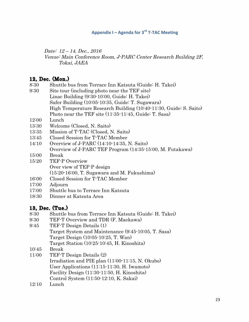
AppendixI–Agendafor3rdT-TACMeeting
Date: 12 – 14, Dec., 2016 Venue: Main Conference Room, J-PARC Center Research Building 2F,
Tokai, JAEA
12, Dec. (Mon.) 8:30 Shuttle bus from Terrace Inn Katsuta (Guide: H. Takei) 9:30 Site tour (including photo near the TEF site) Linac Building (9:30-10:00, Guide: H. Takei) Safer Building (10:05-10:35, Guide: T. Sugawara) High Temperature Research Building (10:40-11:30, Guide: S. Saito) Photo near the TEF site (11:35-11:45, Guide: T. Sasa) 12:00 Lunch 13:30 Welcome (Closed, N. Saito) 13:35 Mission of T-TAC (Closed, N. Saito) 13:45 Closed Session for T-TAC Member 14:10 Overview of J-PARC (14:10-14:35, N. Saito)
Overview of J-PARC TEF Program (14:35-15:00, M. Futakawa) 15:00 Break 15:20 TEF-P Overview Over view of TEF-P design
(15:20-16:00, T. Sugawara and M. Fukushima) 16:00 Closed Session for T-TAC Member 17:00 Adjourn 17:00 Shuttle bus to Terrace Inn Katsuta 18:30 Dinner at Katsuta Area 13, Dec. (Tue.) 8:30 Shuttle bus from Terrace Inn Katsuta (Guide: H. Takei) 9:30 TEF-T Overview and TDR (F. Maekawa) 9:45 TEF-T Design Details (1) Target System and Maintenance (9:45-10:05, T. Sasa) Target Design (10:05-10:25, T. Wan) Target Station (10:25-10:45, H. Kinoshita) 10:45 Break 11:00 TEF-T Design Details (2) Irradiation and PIE plan (11:00-11:15, N. Okubo) User Applications (11:15-11:30, H. Iwamoto) Facility Design (11:30-11:50, H. Kinoshita) Control System (11:50-12:10, K. Sakai) 12:10 Lunch
24
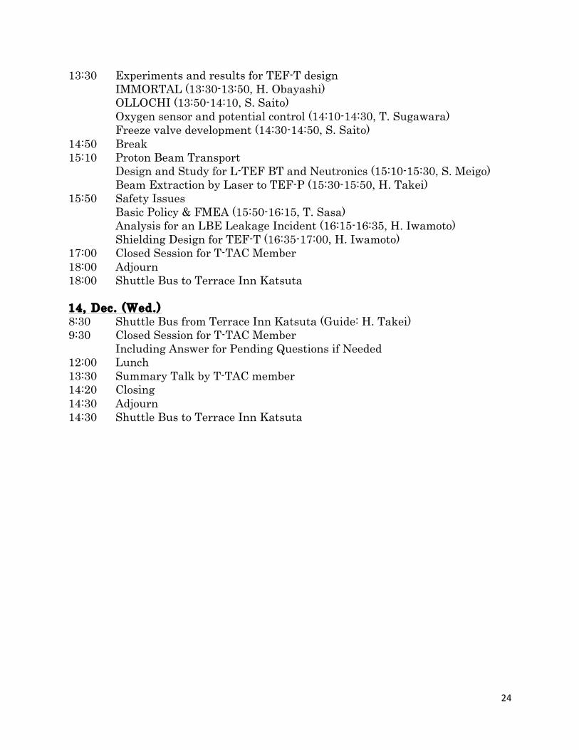
13:30 Experiments and results for TEF-T design IMMORTAL (13:30-13:50, H. Obayashi) OLLOCHI (13:50-14:10, S. Saito)
Oxygen sensor and potential control (14:10-14:30, T. Sugawara) Freeze valve development (14:30-14:50, S. Saito) 14:50 Break 15:10 Proton Beam Transport Design and Study for L-TEF BT and Neutronics (15:10-15:30, S. Meigo) Beam Extraction by Laser to TEF-P (15:30-15:50, H. Takei) 15:50 Safety Issues Basic Policy & FMEA (15:50-16:15, T. Sasa) Analysis for an LBE Leakage Incident (16:15-16:35, H. Iwamoto) Shielding Design for TEF-T (16:35-17:00, H. Iwamoto) 17:00 Closed Session for T-TAC Member 18:00 Adjourn 18:00 Shuttle Bus to Terrace Inn Katsuta 14, Dec. (Wed.) 8:30 Shuttle Bus from Terrace Inn Katsuta (Guide: H. Takei) 9:30 Closed Session for T-TAC Member Including Answer for Pending Questions if Needed 12:00 Lunch 13:30 Summary Talk by T-TAC member 14:20 Closing 14:30 Adjourn 14:30 Shuttle Bus to Terrace Inn Katsuta
25
AppendixII–ChargestoT-TAC2016fromJ-PARC
byDrN.Saito
T-TACwasrequiredtoadviceprimarilyonthefollowingcharges:• Validityofbase-lineparameterstomeettheprimarypurposeofTEFincludingbothTEF-TandTEF-P
thatiscontributingtonucleartransmutationtechnologydevelopment• Feasibility of proton beam transport, LBE target system and related systems for TEF -T including
safetypolicy,operationandmaintenancescheme• Adequacyoftimeline(resourceandschedule)• Inadditiontousual recommendationson facilitydesignandR&Dactivities, it isaskedtopointout
left issuesforcompletingtheTEFdesign,andtoadviceonapproachestosolvetheissuesincludinginternationalcollaborationandPRcampaigns,etc.
26
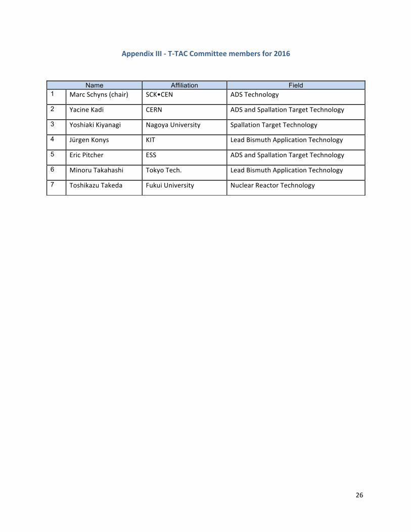
AppendixIII-T-TACCommitteemembersfor2016
Name Affiliation Field 1 MarcSchyns(chair) SCK•CEN ADSTechnology
2 YacineKadi CERN ADSandSpallationTargetTechnology
3 YoshiakiKiyanagi NagoyaUniversity SpallationTargetTechnology
4 JürgenKonys KIT LeadBismuthApplicationTechnology
5 EricPitcher ESS ADSandSpallationTargetTechnology
6 MinoruTakahashi TokyoTech. LeadBismuthApplicationTechnology
7 ToshikazuTakeda FukuiUniversity NuclearReactorTechnology