Middle Tennessee State University1 Banking Relationships $Building Your Financial Future$
Upload
aldous-gilmoreCategory
view
226download
2
T. S. Eugene Ng
eugeneng at cs.rice.edu
Rice University
1
COMP/ELEC 429Introduction to Computer Networks
Lecture 9: IP
Slides used with permissions from Edward W. Knightly, T. S. Eugene Ng, Ion Stoica, Hui Zhang

T. S. Eugene Ng
eugeneng at cs.rice.edu
Rice University
2
Recap
• Cannot build a global network such as the Internet using Ethernet bridges
• Problem 1: Addressing• Problem 2: Routing
• Additionally, a global network should allow heterogeneous technologies (e.g. ATM, circuit-switched networks, Ethernet, etc)
LAN 2
Bridge 2
LAN 5
LAN 3
LAN 1
LAN 4
Bridge 5
Bridge 4Bridge 3
d
Bridge 1

T. S. Eugene Ng
eugeneng at cs.rice.edu
Rice University
3
New Word: Internetwork
• Multiple incompatible LANs can be physically connected by specialized computers called routers.• The connected networks are called an internetwork.
– The “Internet” is one (very big & successful) example of an internetwork
host host host
LAN 1
... host host host
LAN 2
...
router router routerWAN WAN
LAN 1 and LAN 2 might be completely different, totally incompatible LANs (e.g., Ethernet, Wi-Fi, ATM, Circuit-switched)

T. S. Eugene Ng
eugeneng at cs.rice.edu
Rice University
4
Logical Structure of Internet
– Ad hoc interconnection of networks• No particular topology• Vastly different router & link capacities
– Send packets from source to destination by hopping through networks• Router connects one network to another• Different packets may take different routes
host
host
router
routerrouter
router
router
router
EthernetHosts, bridges, switches, hubs, etc
ATM
Wi-Fi

T. S. Eugene Ng
eugeneng at cs.rice.edu
Rice University
5
Adding an Internetwork Layer (IP) for Interoperability
FTP
TCP
IP
Ethernet Ethernet ATM
IP
FTP
TCP
IP
ATM
Router
Host
Bridge ATM Switch
Host

T. S. Eugene Ng
eugeneng at cs.rice.edu
Rice University
6
Issues in Designing an Internetwork
• How do I designate a distant host?– Addressing / naming
• How do I send information to a distant host?– Underlying service model
• What gets sent?
• How fast will it go?
• What happens if it doesn’t get there?
– Routing
• Challenges– Heterogeneity
• Assembly from variety of different networks
– Scalability• Ensure ability to grow to worldwide scale
Internet: Best-effort, datagram networkA kind of lowest common denominator

T. S. Eugene Ng
eugeneng at cs.rice.edu
Rice University
7
Possible Addressing Schemes
• Flat– e.g., every host identified by its 48-bit MAC address– Router would need entry for every host in the world
• Too big (although technology can help this)
• Too hard to maintain as hosts come & go
• Hierarchy– Address broken into segments of increasing specificity
• 713 (Houston) – 348 (Rice area) – 2000 (Particular phone)
– Route to general region and then work toward specific destination
– As people and organizations shift, only update affected routing tables

T. S. Eugene Ng
eugeneng at cs.rice.edu
Rice University
8
An Example of a Binary Hierarchy
DatagramDatagram
Destination address: 1 0 1 1 *
0 *
1 1 *
1 0 *
0 1 *
0 0 *
1 0 1

T. S. Eugene Ng
eugeneng at cs.rice.edu
Rice University
9
IP Addressing• IPv4: 32-bit addresses
– Typically, write in dotted decimal format• E.g., 128.42.198.135
• Each number is decimal representation of byte
– Big-Endian Order
128 42 198 135
80 2a c6 87
0 8 16 24 31
0100 0000 0010 1010 1100 0110 1000 0111
Decimal
Hexadecimal
Binary

T. S. Eugene Ng
eugeneng at cs.rice.edu
Rice University
10
IP Addressing and Forwarding• Routing Table Requirement
– For every possible destination IP address, give next hop– Nearly 232 (4.3 x 10⁹) possibilities!
• Hierarchical Addressing Scheme
– Address split into network ID and host ID– All packets to given network follow same route
• Until they reach destination network
– Fields• pfx Prefix to specify split between network & host IDs• network 2x possibilities• host 2y possibilities
pfx network host
x y

T. S. Eugene Ng
eugeneng at cs.rice.edu
Rice University
11
IP Address Classes
• Class A
– mit.edu: 18.7.22.69
• Class B
– rice.edu: 128.42.129.23
• Class C
– adsl-216-63-78-18.dsl.hstntx.swbell.net: 216.63.78.18
• Classes D, E, F– Not commonly used
0 network host
7 24
10 network host
14 16
110 network host
21 8
First octet: 1–126
First octet: 128–191
First octet: 192–223
T. S. Eugene Ng
eugeneng at cs.rice.edu
Rice University
12
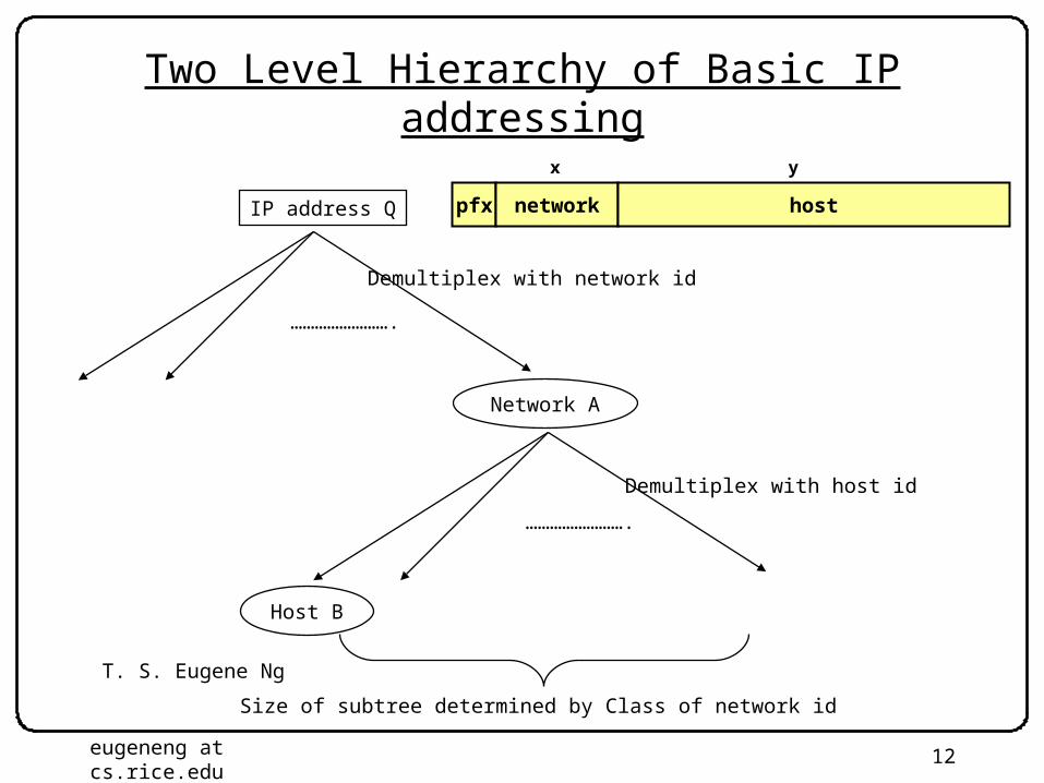
Two Level Hierarchy of Basic IP addressing
…………………….
Network A
…………………….
Host B
Demultiplex with network id
Demultiplex with host id
IP address Q
Size of subtree determined by Class of network id
pfx network host
x y

T. S. Eugene Ng
eugeneng at cs.rice.edu
Rice University
13
IP Address Classes
• Partitioning too Coarse– No local organization needs 16.7 million hosts
• Large organization likely to be geographically distributed– Many organizations must make do with multiple class C’s
• Too many different Network IDs– Routing tables must still have 2.1 million entries
Class Count Hosts
A 27-2 = 126 (0 & 127 reserved)
224-2 = 16,777,214
(all 0s, all 1s reserved)
B 214 = 16,398 216-2 = 65,534
(all 0s, all 1s reserved)
C 221 = 2,097,512 28-2 = 254
(all 0s, all 1s reserved)
Total 2,114,036

T. S. Eugene Ng
eugeneng at cs.rice.edu
Rice University
14
Within Organization: Subnetting
• Add Another Layer to Hierarchy
– From the outside, appears as one monolithic network• Single entry in routing table
– Within network, manage as multiple subnetworks• Internal routers must route according to subnet ID
• Subnet Mask– Way to specify break between subnet ID and host ID
– Similar masks used in many contexts
pfx network host
x y
subnet
z
pfx network hostsubnet
1 1 1 1 1 1 1 1 1 1 1 1 1 1 1 1 0 0 0 0 0 0 0 0 0 0 0 0 0 0 0 0

T. S. Eugene Ng
eugeneng at cs.rice.edu
Rice University
15
Subnetting
…………………….
Network A
…………………….
Subnet S
Demultiplex with network id
Demultiplex with subnet id
IP address Q
…………………….Demultiplex with host id
Size of subtree determined byLength of subnet mask
Host B
pfx network host
x y
subnet
z

T. S. Eugene Ng
eugeneng at cs.rice.edu
Rice University
16
Routing Table
• Address 128.42.222.198 matches 4 entries• Longest Prefix Match
– Select entry with longest sequence of 1’s in mask– Most specific case
Address Pattern Subnet Mask Next Hop
128.42.222.0 255.255.255.0 R1
128.42.128.0 255.255.128.0 R2
18.0.0.0 255.0.0.0 R3
0.0.0.0 0.0.0.0 R4
128.42.0.0 255.255.0.0 R5

T. S. Eugene Ng
eugeneng at cs.rice.edu
Rice University
17
Improving the Hierarchy
• Basic Idea of Hierarchy is Good– Organizations of different sizes can be assigned different
numbers of IP addresses
• Shortcomings of Class-Based Addressing– Class A too coarse; Class C too fine; not enough Class B’s– When fully deployed would have too many entries in routing
table (2.1 million)
• Solution– Hierarchy with finer gradation of network/host ID split

T. S. Eugene Ng
eugeneng at cs.rice.edu
Rice University
18
Subnetting
…………………….
Network A
…………………….
Subnet S
Demultiplex with network id
Demultiplex with subnet id
IP address Q
…………………….Demultiplex with host id
Size of subtree determined byLength of subnet mask
Host B
pfx network host
x y
subnet
z
2.1 million possibilities!
T. S. Eugene Ng
eugeneng at cs.rice.edu
Rice University
19
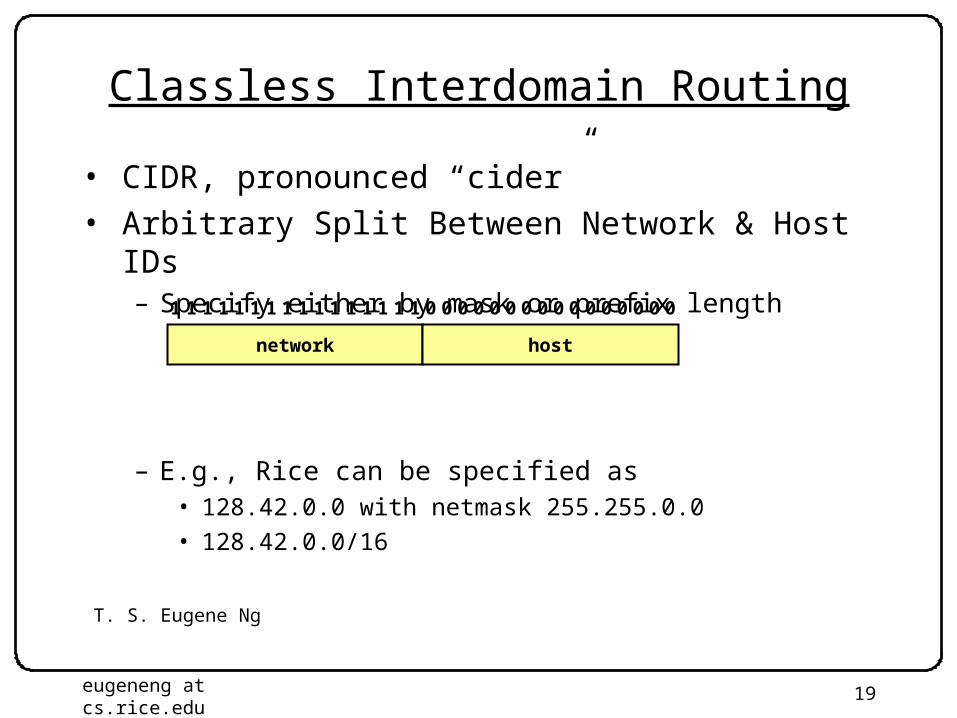
Classless Interdomain Routing
• CIDR, pronounced “cider”• Arbitrary Split Between Network & Host IDs
– Specify either by mask or prefix length
– E.g., Rice can be specified as• 128.42.0.0 with netmask 255.255.0.0
• 128.42.0.0/16
network host
1 1 1 1 1 1 1 1 1 1 1 1 1 1 1 1 0 0 0 0 0 0 0 0 0 0 0 0 0 0 0 0

T. S. Eugene Ng
eugeneng at cs.rice.edu
Rice University
20
Aggregation with CIDR– Original Use: Aggregate Class C Addresses– One organization assigned contiguous range of class C’s
• e.g., Microsoft given all addresses 207.46.192.X -- 207.46.255.X• Specify as CIDR address 207.46.192.0/18
• Represents 26 = 64 class C networks
– Use single entry in routing table• Just as if were single network address
207 46 192 0
cf 2e c0 00
0 8 16 24 31
1100 1111 0010 1110 11xx xxxx xxxx xxxx
Decimal
Hexadecimal
Binary
Upper 18 bits frozen Lower 14 bits arbitrary

T. S. Eugene Ng
eugeneng at cs.rice.edu
Rice University
21
Routing Table Entry Examples
• Snapshot From MAE-West Routing Table– Probably out of date
– Note hole in table: Nothing covers bytes 96 – 127
Address Prefix Length Third Byte Byte Range
207.46.0.0 19 000xxxxx2 0 – 31
207.46.32.0 19 001xxxxx2 32 – 63
207.46.64.0 19 010xxxxx2 64 – 95
207.46.128.0 18 10xxxxxx2 128 – 191
207.46.192.0 18 11xxxxxx2 192 – 255microsoft.com: 207.46.245.214 & 207.46.245.222

T. S. Eugene Ng
eugeneng at cs.rice.edu
Rice University
22
Splitting with CIDR
• Expose subnetting structure to external routers• Example
– Class A address 12.X.X.X has 413 entries in routing table– Prefix lengths 8--24– attbi.com
• Backbone services of AT&T
– Geographically distributed• Don’t want all packets to concentrate to single region

T. S. Eugene Ng
eugeneng at cs.rice.edu
Rice University
23
Size of Complete Routing Table
– Source: www.cidr-report.org– Shows that CIDR has kept # table entries in check
• Currently require 124,894 entries for a complete table
• Only required by backbone routers

T. S. Eugene Ng
eugeneng at cs.rice.edu
Rice University
24
Important Concepts
– Hierarchical addressing critical for scalable system• Don’t require everyone to know everyone else
• Reduces amount of updating when something changes
– Non-uniform hierarchy useful for heterogeneous networks• Class-based addressing too coarse
• CIDR helps
• Move to IPv6 due to limited number of 32-bit addresses
– Implementation Challenge• Longest prefix matching much more difficult than when no
ambiguity

T. S. Eugene Ng
eugeneng at cs.rice.edu
Rice University
25
IP Service Model• Datagram
– Each packet self-contained• All information needed to get to destination
• No advance setup or connection maintenance
– Analogous to letter or telegram
0 4 8 12 16 19 24 28 31
ver-sion
HLen TOS Length
Ident Flags Offset
TTL Protocol Checksum
Source Address
Destination Address
Options (if any)
Data
Header
IPv4 PacketFormat

T. S. Eugene Ng
eugeneng at cs.rice.edu
Rice University
26
IP Header Fields: Word 1
•Version: IP Version– 4 for IPv4
•HLen: Header Length– 32-bit words (typically 5)
•TOS: Type of Service– Priority information
•Length: Packet Length– Bytes (including header)
– Header format can change with versions• First byte identifies version
– Length field limits packets to 65,535 bytes• In practice, break into much smaller packets for network
performance considerations
0 4 8 12 16 19 24 28 31
ver-sion
HLen TOS Length
Identifier Flags Offset
TTL Protocol Checksum
Source Address
Destination Address
Options (if any)
Data

T. S. Eugene Ng
eugeneng at cs.rice.edu
Rice University
27
IP Header Fields: Word 3
•TTL: time to live– Decrement by one at each
intermediate router
– Prevent looping forever
•Protocol– Protocol of next layer (in “data”)
– E.g. TCP (6), UDP (17)
•Checksum– Of IP header
– Protocol field used for demultiplexing
– Checksum re-computed at each router• Why?
– TTL field used to implement traceroute
0 4 8 12 16 19 24 28 31
ver-sion
HLen TOS Length
Identifier Flags Offset
TTL Protocol Checksum
Source Address
Destination Address
Options (if any)
Data

T. S. Eugene Ng
eugeneng at cs.rice.edu
Rice University
28
IP Header Fields: Words 4&5
•Source Address– 32-bit IP address of sender
•Destination Address– 32-bit IP address of destination
– Like the addresses on an envelope
– In principle, globally unique identification of sender & receiver
• In practice, there are contexts where either source or destination are not the ultimate addressees
0 4 8 12 16 19 24 28 31
ver-sion
HLen TOS Length
Identifier Flags Offset
TTL Protocol Checksum
Source Address
Destination Address
Options (if any)
Data

T. S. Eugene Ng
eugeneng at cs.rice.edu
Rice University
29
IP Fragmentation
• Every Network has Own Maximum Transmission Unit (MTU)– Largest IP datagram it can carry within its own packet frame
• E.g., Ethernet is 1500 bytes
– Don’t know MTUs of all intermediate networks in advance
• IP Solution– When hit network with small MTU, fragment packets
• Might get further fragmentation as proceed farther
– Reassemble at the destination• If any fragment disappears, delete entire packet
host
host
routerrouter
MTU = 4000
MTU = 1500
MTU = 2000

T. S. Eugene Ng
eugeneng at cs.rice.edu
Rice University
30
IP Header Fields: Word 2
•Identifier– Unique identifier for original
datagram• Typically, source increments
counter every time sends packet
•Flags (3 bits)– M flag: This is not the last fragment
•Offset– Byte position of first byte in
fragment 8– Byte position must be multiple of 8
– Each fragment carries copy of IP header• All information required for delivery to destination
– All fragments comprising original datagram have same identifier
– Offsets indicate positions within datagram
0 4 8 12 16 19 24 28 31
ver-sion
HLen TOS Length
Identifier Flags Offset
TTL Protocol Checksum
Source Address
Destination Address
Options (if any)
Data

T. S. Eugene Ng
eugeneng at cs.rice.edu
Rice University
31
IP Fragmentation Example #1
hostrouter
MTU = 4000
IPHeader
IPData
Length = 3820, M=0

T. S. Eugene Ng
eugeneng at cs.rice.edu
Rice University
32
IP Fragmentation Example #2
routerrouter
MTU = 2000
IPHeader
IPData
Length = 3820, M=0
3800 bytes
IPHeader
IPData
Length = 2000, M=1, Offset = 0
1980 bytes
IPData
IPHeader
Length = 1840, M=0, Offset = 1980
1820 bytes
Offset must be a multiple of 8, but ignored in theseexamples for simplicity
Offset must be a multiple of 8, but ignored in theseexamples for simplicity

T. S. Eugene Ng
eugeneng at cs.rice.edu
Rice University
33
IP Fragmentation Example #3
IPHeader
IPData
Length = 2000, M=1, Offset = 0
1980 bytes
IPData
IPHeader
Length = 1840, M=0, Offset = 1980
1820 bytes
hostrouter
MTU = 1500
IPHeader
IPData
Length = 1500, M=1, Offset = 0
1480 bytes
IPHeader
IPData
Length = 520, M=1, Offset = 1480
500 bytes
IPHeader
IPData
Length = 1500, M=1, Offset = 1980
1480 bytes IPHeader
IPData
Length = 360, M=0, Offset = 3460
340 bytes

T. S. Eugene Ng
eugeneng at cs.rice.edu
Rice University
34
IP Reassembly
– Performed at final destination
– Fragment with M=0 determines overall length
• (360-20)+3460
• Challenges– Fragments might arrive out-of-order
• Don’t know how much memory required until receive final fragment
– Some fragments may be duplicated• Keep only one copy
– Some fragments may never arrive• After a while, give up entire process
– Significant memory management issues
IPHeader
IPData
Length = 1500, M=1, Offset = 0
IPHeader
IPData
Length = 520, M=1, Offset = 1480
IPHeader
IPData
Length = 1500, M=1, Offset = 1980
IPHeader
IPData
Length = 360, M=0, Offset = 3460
IPData
IPData
IPData
IPData

T. S. Eugene Ng
eugeneng at cs.rice.edu
Rice University
35
Frag. & Reassembly Concepts
– Demonstrates Many Internet Concepts
• Decentralized– Every network can choose MTU
• Connectionless Datagram Protocol– Each (fragment of) packet contains full routing information– Fragments can proceed independently and along different
routes
• Fail by Dropping Packet– Destination can give up on reassembly– No need to signal sender that failure occurred
• Keep Most Work at Endpoints– Reassembly

T. S. Eugene Ng
eugeneng at cs.rice.edu
Rice University
36
Frag. & Reassembly Reality
• Reassembly Fairly Expensive– Copying, memory allocation– Want to avoid
• MTU Discovery Protocol– Protocol to determine MTU along route
• Send packets with “don’t fragment” flag set• Keep decreasing message lengths until packets get through• May get a “can’t fragment error” message from router which contains
the correct MTU
– Assumes every packet will follow same route• Routes tend to change slowly over time
• Common Theme in System Design– Fragmentation is handled as a special case by slower general
processor in router– Assure correctness by implementing complete protocol– Optimize common cases to avoid full complexity