T russ - maker · Computer Aided Design - ArchiCAD 62 SLABS Place on the ground story a slab 360mm...
22
Truss-maker 47 Truss-maker Picture WINDOW HOUSE-2002 Arh. Shigeru Ban ”For me there is no difference between a temporary and a permanent building. It is more easy to build temporary. If people love it, it becomes permanent.” Shigeru Ban DEFINING THE PLAN Set the drawing units to milimeters. In STORY SETTINGS (Ctrl+7), set the heights of the stories to 2600. In this tutorial you will study how to: TrussMaker o create and edit a truss ComplexProfiles o create a canopy using complex profiles o create a hand rail using complex profiles create a custom stair
Transcript of T russ - maker · Computer Aided Design - ArchiCAD 62 SLABS Place on the ground story a slab 360mm...

Truss-maker
47
Truss-maker Picture WINDOW HOUSE-2002 Arh. Shigeru Ban ”For me there is no difference between a temporary and a permanent building. It is more easy to build temporary. If people love it, it becomes permanent.” Shigeru Ban
DEFINING THE PLAN
Set the drawing units to milimeters. In STORY SETTINGS (Ctrl+7), set the heights of the stories to 2600.
In this tutorial you will study how to: TrussMaker
o create and edit a truss ComplexProfiles
o create a canopy using complex profiles
o create a hand rail using complex profiles
create a custom stair
Computer Aided Design - ArchiCAD
48
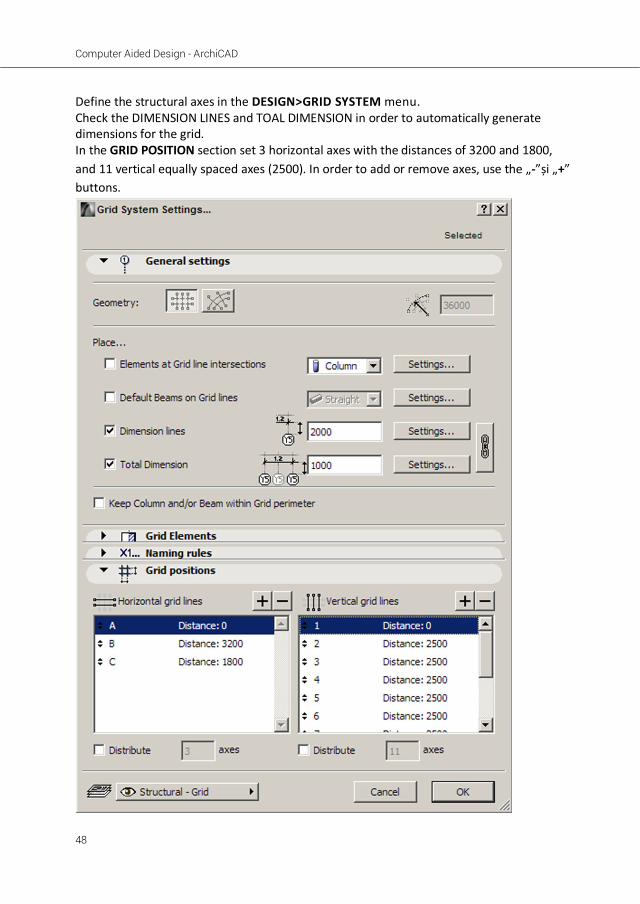
Define the structural axes in the DESIGN>GRID SYSTEM menu. Check the DIMENSION LINES and TOAL DIMENSION in order to automatically generate dimensions for the grid. In the GRID POSITION section set 3 horizontal axes with the distances of 3200 and 1800, and 11 vertical equally spaced axes (2500). In order to add or remove axes, use the „-”și „+” buttons.

Truss-maker
49
Access WINDOW>PALETTES>CONTROL BOX. Using control box, offet a polyline 400 mm outside the overall contour defined by the grid.
DEFINING THE STRUCTURE
On the floor plan drag a copy of the vertical axes. In order to do this, suspend the groups (ALT+G). In the plan view, drag a copy of the vertical axes to use them as a guide for the following truss scheme. Follow the image below, using the specified colors:
Type a – color code 1 Type b – color code 4 Type c – color code 20
The line colors can be manually input in the INFOBOX after selecting them. Avoid drawing overlapping lines. This would cause errors in truss generation.
!

Computer Aided Design - ArchiCAD
50
Select all the lines and acces the DESIGN>DESIGN EXTRAS> TRUSSMAKER> CREATE TRUSS menu.
From the left section choose ROLLED STEEL PROFILE. In the ATTRIBUTES section, set the level dimension of the truss (-350 mm) and the surface material (Paint-Titanium White). In the TRUSS PROFILES section select each color and set the dimensions accordingly: Profile a – de tip H – 300x300x16 Profile b – de tip H – 250x250x14 Profile c – round tie rod – Diameter 115 mm, Resolution 50, End length 146
In order to set the round section for the diagonal tie rod (color 20) click&hold on the profile next to the color
!

Truss-maker
51
In the STEEL JUNCTIONS section select the WITH JUNCTION PLATES mode using the follow dimensions: T=10 L=100 M=100 Save the truss as Truss 1
The truss will show like a usual beam. Move it on the A axis, using the intersection of the truss with the axis 11, as an anchor.

Computer Aided Design - ArchiCAD
52
In the plan view, copy and rotate the horizontal axes (A,B,C) to easily draw the truss schemes of the transversal structural elements.
Draw the schemes of the 2,3,4,5 trusses, and generate them as previously shown, naming them as such.
In order to achieve clean intersections between truss profiles, stretch the horizontal lines of the schemes on both sizes, 150mm towards the exterior. Reuse the drawings to make slight editing and ease your work. Set the level dimension for all trusses to -350. Copy the trusses and rotate them by 90 degrees, as the schemes are seen from the left side façade (follow the A,B,C axes). Their position will be as follows: TRUSS2 – 2 pcs – axes 1, 11 TRUSS3 – 2 pcs – axes 2,10 TRUSS4 – 6 pcs – axes 3,4,5,6,8,9 TRUSS5 - 1 pcs – axis 7 TRUSS6 - 1 pcs – axis C
Truss2
Truss3
Truss 4
Truss 5
In case an error occurs in the generation of the truss, check if the lines of the truss overlap. Truss-Maker cannot generate two identical elements on the same position.
!
Suspend the groups in order to copy the horizontal axes
!

Truss-maker
53
For the main entrance façade (located in the upper part of the plan), copy the scheme used for Truss 1, delete the diagonal lines (type c), and generate TRUSS 7 modifying the type and dimensions of the profiles used for type b: round tie rod – Diameter 70 mm, Resolution 36, End length 100.
The metal beams situated on axis B can be generated using beams from the object library, or as well as the others, using Truss Maker, as they are coplanar. Draw three horizontal axes reusing the schemes of Truss 1 or 7.
Computer Aided Design - ArchiCAD
54
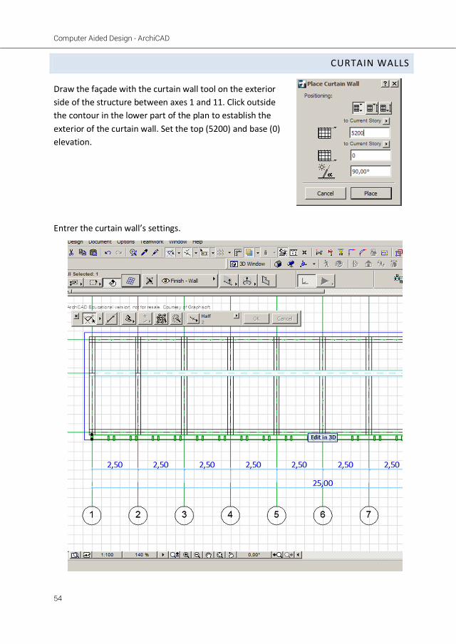
CURTAIN WALLS
Draw the façade with the curtain wall tool on the exterior side of the structure between axes 1 and 11. Click outside the contour in the lower part of the plan to establish the exterior of the curtain wall. Set the top (5200) and base (0) elevation. Entrer the curtain wall’s settings.

Truss-maker
55
In the SCHEME section remove one of the vertical registers of the grid from Primary Gridlines sector by selecting it and pressing the „-” button. Set the width of the remaining register to 2500. In the Secondary Gridlines sector define the dimensions of the three grid registers (2250, 350,2250). Make the wall transparent by clicking in ithe PREVIEW window on the dark cells of the grid.
Define the dimensions of the structural elements of the curtain wall as follows: Boundary: a:100, b:250, h:250, d:30, w:20. Material: Paint-Titanium White

Computer Aided Design - ArchiCAD
56
Mullion: a:50, b:250, h:200, d:0, w:0. Surface Material: Paint-Titanium White. Transom: a:50, b:100, h:110, d:5, w:20. Surface Material: Paint-Titanium White.
Go to curtain Wall system section in the left panel and set the frame material to Steel.

Truss-maker
57
In the 3d window select the curtain wall and press „Edit”. Select the elements corresponding to the ground level between axes 2-10 and remove them by pressing the DELETE key.

Computer Aided Design - ArchiCAD
58
In the plan view select the curtain wall and mirror it to create the other façade. Edit the curtain wall ]n the 3D window. Select the mullions in the axes 3,5,7,9 and set the dimensions as follows: a:10, b:40, h:40, d:0, w:0. Surface Material: Paint-Titanium White.

Truss-maker
59
The side facades are opaque, but will be generated as well with the curtain wall tool, with a total width of 5100 mm. The elevation dimensions will be the same as the main facades. Change thje material of the grid cells from „Main” to „Distinct” by clicking in the white grid cells in the Preview window. Use the following dimensions:
one vertical register (1700mm wide) 6 equal horizontal register: 1,2,3,5,6,7 (750mm) one middlehorizontal register: 4 (350mm)
Set the Surface material of the strustructural elements to Paint-Titanium White.

Computer Aided Design - ArchiCAD
60
THE CANOPY
Draw a transversal section (S-01) and draw a polyline to mach the dimensions and position from the image below. Fill the contour using FILL and MAGIC WAND. Select the fill and copy it to the Clipboard (CTRL+V). Acces the DESIGN>COMPLEX PROFILES>PROFILE MANAGER menu.

Truss-maker
61
Start a new profile and name it canopy. Paste (CTRL+V) the profile and match the origin to be at the base of the profile.
Press on the STORE PROFILE button. The profile will show in the preview window. At the base of the window click on OVERRIDE button and check the OVERRIDE SURFACES box in order to be able to change the Surface Material (Paint-Titanium White). Click apply to save the changes. Double click on WALL in the toolbox to enter its settings.
Select the complex profile type for the wall and choose the canopy profile stored previously. Set the elevation from project 0 to 2200mm. Draw the canopy between axes 2-10. To create the terrace, select the fill of the profile in the section window and mirror it as shown in the image. After storing the new profile which will be named terrace, repeat the steps above to define it in the plan as well between axes 2-10, and the elevation project 0 set to 0.

Computer Aided Design - ArchiCAD
62
SLABS
Place on the ground story a slab 360mm thick using the polyline drawn in the beginning of the exercise. Draw slabs of the same type and dimensions on the first level and for the roof both between the axes of the structure.
STAIR AND HAND RAIL
You will draw the stair structure and the handrail using TrussMaker as well.

Truss-maker
63
Draw the scheme of the handrail and the stairs having 280mm wide treads and 153mm high risers. The handrail will be coplanar with the stair string, 800mm high. Delete the last tread-riser pair, as it will be defined by the upper slab. Use 3 colors for the scheme, in order to define 3 different types of profiles as in the image below: In TrussMaker use the Hollow Section profiles and set the dimensions as follows: Stairs: 50x50x5 Secondary profiles of the hand rail: 20x20x3 Main profiles of the hand rail: 50x50x3. After saving the truss, drag a copy 900 mm from the original object and post them as shown in the drawing below:

Computer Aided Design - ArchiCAD
64
Generate the stair with StairMaker.
Before generating or editing a stair it is highly recommended to save your project.
!

Truss-maker
65
Launch StairMaker and choose the STRAIGHT RUN Stair. Input the following dimensions: Tread Settings: 2*Riser+Run > 5803 2*Riser+Run < 650
3 The original stair in this project does not follow the usual rule (2h+L=62÷64)
Tread width : 320 mm Riser: 153 mm Lock the values for both. Number of risers: 17 Stair width: 850 mm

Computer Aided Design - ArchiCAD
66
Choose the simple stairs structure type:
In the Tread Settings set the nosing as well as the Tread thickness to 40mm. Set the Surface material to Wood – Oak light and the section fill to Wood.

Truss-maker
67
Choose NO RAILING in the Railing settings section.

Computer Aided Design - ArchiCAD
68
Check ia a section the position of the stairs relative to the rails previously generated with TrussMaker. The treads should be centered inside the metal profiles (there should be a 5mm offset around the tread – representing the material thickness of the metal profiles).