T-III / T-IV - WORLD electronics · FREEDOM Tool Features ... A Graphical User Interface,...
60
Transcript of T-III / T-IV - WORLD electronics · FREEDOM Tool Features ... A Graphical User Interface,...

T-III / T-IV

This is Your Software Security Access Key: DO NOT LOSE IT !
This security device must be plugged into the notebook computer’s USB port whenever the FREEDOM Tool Software is to be run.

List of Trademarks
Windows is a trademark / product of Microsoft Corporation.
Microsoft is a registered trademark.
Traflomatic IIII are trademarks of ThyssenKrupp formerly Dover Elevator Systems, Inc.
Traflomatic IV are trademarks of ThyssenKrupp formerly Dover Elevator Systems, Inc.
WORLD electronics, the WORLD electronics' logo, FREEDOM Tool, and FREEDOMWare are registered trademarks of WORLD electronics Sales and Service, Inc.
Copyright 1997-2007 by WORLD electronics®. All rights reserved. Printed in the United States of America. Except as permitted under the United States Copyright Act of 1976, no part of this publication may be reproduced or distributed in any form or by any means, or stored in a data base or retrieval system, without the prior written permission of WORLD electronics. Further, this publication and features described herein are subject to change without notice from the publisher.

Table of Contents Introduction ...................................................................................................................................... 1
FREEDOM Tool Features ............................................................................................................... 1 Minimum Hardware and Software Requirements .................................................................. 1 How to contact WORLD electronics ......................................................................................... 2 Package Contents ....................................................................................................................... 3
RS232 Serial Cable (DB9 to DB25 – 6ft) – (7502.9030) .......................................................... 3 T-III Card Edge to DB-25 Adapter Board – (7502.9029) ....................................................... 3 Security Key (6015.0014) ........................................................................................................... 4 Installation CD (6015.0002) ...................................................................................................... 5
Installing the Traflomatic-III Software Module ......................................................................... 6 Installing the Traflomatic-IV Software Module ....................................................................... 11
Executing the FREEDOM Tool Shell Program ............................................................................. 19 Getting Started .............................................................................................................................. 21
Starting the Traflomatic-III or Traflomatic-IV Software Module ........................................... 21 General Description ...................................................................................................................... 24
The Menu ..................................................................................................................................... 25 File .............................................................................................................................................. 25 Port Set-Up ................................................................................................................................ 25 Connect .................................................................................................................................... 26 Disconnect ............................................................................................................................... 26 Exit .............................................................................................................................................. 26
Password ...................................................................................................................................... 27 Commands.................................................................................................................................. 27 Transfer ......................................................................................................................................... 28
Save Elevator Parameters ..................................................................................................... 28 Restore Elevator Parameters ................................................................................................. 29
Definition Bar ............................................................................................................................... 30 Terminal Window ........................................................................................................................ 31 The Feature Bar ........................................................................................................................... 32
Change Elevator ..................................................................................................................... 32 Car Mode ................................................................................................................................. 32 Group Mode ............................................................................................................................ 33 Selection Bar ............................................................................................................................ 33 Adjustments .............................................................................................................................. 34 Job Info ..................................................................................................................................... 35 Timers ......................................................................................................................................... 36 CSW ........................................................................................................................................... 36 Displays...................................................................................................................................... 40 Faults .......................................................................................................................................... 41 SAVE ........................................................................................................................................... 42 RESTORE ..................................................................................................................................... 42 UP 1 Floor .................................................................................................................................. 42 Down 1 Floor ............................................................................................................................ 43 Auto Tune ................................................................................................................................. 43 Automatic Set-Up .................................................................................................................... 43

System Test................................................................................................................................ 46 Security ...................................................................................................................................... 46 Terminal Back-Up ..................................................................................................................... 47 Load Weigher .......................................................................................................................... 48 NTS .............................................................................................................................................. 48 ETS .............................................................................................................................................. 49 CALLS ......................................................................................................................................... 49 Lockouts .................................................................................................................................... 51 REPEAT ....................................................................................................................................... 51 Reference ................................................................................................................................. 51 Car/Group ................................................................................................................................ 52 Scan Assignment ..................................................................................................................... 53 Code Blue ................................................................................................................................. 55 Init. Security .............................................................................................................................. 55

1
Introduction:
The FREEDOM Tool is a sophisticated software tool that allows the operator to service various elevators and elevator control systems. The software allows the operator to simultaneously view independent operations within the elevator system by opening windows to those systems / operations of interest. The selected windows may be left open during the maintenance / repair session and accessed when desired.
This User’s Guide and Reference, part number 7502.9034, has been written to specifically target the Dover Traflomatic-III and Traflomatic-IV elevator control systems. All references to FREEDOM Tool throughout this manual imply that it pertains solely to the software system that supports the Traflomatic-III and Traflomatic-IV elevator control systems.
FREEDOM Tool Features:
The FREEDOM Tool is a Graphical User Interface (GUI) and provides all the functions necessary to service the Dover Traflomatic-III and Traflomatic-IV elevator control systems. The software runs under the Microsoft Windows operating system and provides the following features:
A Graphical User Interface, representing the adjustment and diagnostic capabilities of the elevator service tool residing within the Dover Traflomatic-III and Traflomatic-IV elevator control systems, makes it easy for the user to learn and adjust the elevator control system mentioned within this manual.
Simple point and click operations. The computer does all necessary commands for the user in the background.
The FREEDOM Tool is fully comparable with the OEM’s Traflomatic-III and IV elevator service tool with exception to the ability to display I/O statuses in REAL TIME.
Minimum Hardware and Software Requirements:
The software is provided as a package by WORLD electronics and is installed on a PC running with Microsoft Windows based Operating systems which have the following characteristics:
A Pentium or equivalent microprocessor.
Windows 98, Windows Me, Windows NT, Windows XP or Windows 2000 Operating System.
CD-ROM Drive
Mouse, Trackball, or other pointing device.
1 USB (Universal Serial Bus) Port or 1 RS-232 and 1 Parallel Printer Port
The FREEDOM Tool software is not capable of being executed without a sophisticated security key that is to be connected to the USB port of the computer at the time of the FREEDOM Tool execution. A standard 9-Pin to 25-Pin RS-232 cable is required. One of these is provided in the original software package. If needed, WORLD can provide additional cables at a minimal cost, the WORLD part number for this part is: 7502.9030. If the host PC does not have a DB-9 RS-232 serial port, a USB to RS-232 converter can be used(Not provided in original software package). WORLD electronics’ has these converters in inventory. The part number for an USB to RS-232 converter box is: 7502.9063.

2
How to contact WORLD electronics:
If you are having any problems operating the FREEDOM Tool, feel free to contact us at the following location. We value you as a customer and welcome any comments concerning the use of the FREEDOM Tool.
WORLD electronics Phone: 1-800-523-0427 3000 Kutztown Road Phone: (610) 939-9800 Reading, PA 19605-2617 Fax: (610) 939-9895
E-mail:
Elevator Sales: [email protected]
Service: [email protected]
FREEDOM Tool: [email protected]
When calling WORLD electronics for assistance, have your product serial number, the model computer being used, operating system type, and the error description ready.

3
Package Contents (Hardware Components):
RS232 Serial Cable (DB9 to DB25 – 6 Ft) - (7502.9030):
The RS232 Serial Cable provides the connection between the Traflomatic-III and IV Controller CPU boards and the Notebook Computer on which the FREEDOM Tool Software Module is loaded. Without this cable, the Traflomatic-III and Traflomatic-IV FREEDOMWare software module will not communicate with elevator controllers. Refer to Figure 1.
Figure 1
T-III Card Edge to DB-25 Adapter Board - (7502.9029):
Most Traflomatic-III elevator controllers have a DB-25 connector on the controller rack in order to allow the service tool to communicate with the elevator’s CPU board. In some cases this connection has not been wired. To allow the FREEDOM Tool to connect to Traflomatic-III’s where this connection has not been wired; WORLD electronics has included a Card Edge to DB25 Adapter board. Refer to Figure 2. This board slides on the exposed card edge of the Traflomatic-III CPU board and provides the correct wiring connections so that the FREEDOM Tool may communicate via the 9 to 25 pin RS232 cable.
Figure 2

4
Security Key (6015.0014):
Figure 3
The FREEDOM Tool Software can be loaded on any computer, but only one(1) instance of the program can be run at any single time. To ensure this, WORLD electronics protects itself and its FREEDOM Tool software by utilizing a sophisticated security device that must be plugged into the Notebook Computer USB port prior to operating the FREEDOM Tool software(Figure 3). This security key is unique to every FREEDOM Tool and must be plugged into the Notebook PC while the FREEDOM Tool software is running. The security key is not to be confused with the serial cable or adapter board mentioned earlier.
WARNING! - It is extremely important that this security key is not lost. The replacement value of this device is equal to the dollar value of the FREEDOM Tool software module(s) purchased from WORLD electronics. This cost is in thousands of dollars. Please take the steps necessary to safeguard yourself against loss of the security device.

5
Installation CD (6015.0002):
All software related to the operation of the FREEOM Tool is located on the FREEDOMWare Installation CD. To access the installation program located on the CD-ROM, simply insert the FREEDOMWare Installation CD into the Notebook PC’s CD-ROM Drive.
Figure 4
Upon insertion the installation program should launch allowing the user access to the installation routines and reference manuals for all available FREEDOM Tool Software Modules (Figure 4). Please refer to the section labeled Installing the Traflomatic-III and Traflomatic-IV Software Modules for instructions on installing the FREEDOM Tool Software specifically for Traflomatic-III and Traflomatic-IV.

6
Installing the Traflomatic-III Software Modules:
The installation procedure for the Traflomatic-III Software Module is described as follows:
1. Insert the FREEDOMWare Installation CD into the Notebook PC’s CD-ROM Drive. After approximately 10 seconds a window will appear titled FREEDOMWare – FREEDOM Tool Software Module Installer. Please refer to Figure 5.
Figure 5
If this window does not appear please do the following:
a) Select Start.
b) Select Run.
c) Type the following into the field: d:\startup.exe
(Note: substitute “d:” with the Notebook Pc’s designation for the CD-ROM Drive)
d) Click OK with the PC’s pointing device and the installation program will run.

7
2. After selecting the Install pushbutton associated with the Traflomatic-III section of the FREEDOMWare Installer, the Install Shield Wizard will run showing a window similar to the one shown in Figure 6. To continue with the setup of the Traflomatic software module simply click the Next pushbutton with the PC’s pointing device.
Figure 6
3. After selecting Next, a Registration Info window will appear as in Figure 7. In this window the user will need to fill in the fields beside User Name:, Company Name:, and Serial Number:. The Serial Number can be obtained from a label located on the Traflomatic-III and IV Module’s Security Key. A second location where the serial number can be found is the side of the Traflomatic-III and IV Software Module’s Product Box.
Figure 7

8
4. After entering all the information into the 3 separate fields, the Next pushbutton will appear allowing the installation to continue (Refer to Figure 8). Select Next to continue with the installation.
Figure 8
5. The Ready to Install the Program window will now appear as in Figure 9. This window informs the user that the installation is ready to begin and instructs the user to select the Install pushbutton to begin the software installation process. At this time select the Install pushbutton with the PC’s pointing device.
Figure 9

9
6. The Setup Status window will appear (Figure 10) showing the user the status of the installation procedure. Immediately upon completion of copying the FREEDOM Tool software, the Installation program will begin installing the necessary files for the Security Key Device. Upon the completion of the Security Key Software Installation a window similar to Figure 11 will appear. This window informs the user that the Az-Tech Device Drivers Setup is complete and the user should select Finish to complete the installation. At this time select the Finish pushbutton on the screen to complete the Az-Tech Device Driver Setup and continue with the FREEDOMWare Installation.
Figure 10
Figure 11

10
7. After a brief delay another window will appear(Figure 12) informing the user that the FREEDOMWare installation is complete and instructs the user to once again select the Finish pushbutton to complete the FREEDOMWare installation.
Figure 12

11
Installing the Traflomatic-IV Software Module:
The installation procedure for the Traflomatic-IV Software Module is described as follows:
1. Insert the FREEDOMWare Installation CD into the Notebook PC’s CD-ROM Drive. After approximately 10 seconds a window will appear titled FREEDOMWare – FREEDOM Tool Software Module Installer. Please refer to Figure 13.
Figure 13
If this window does not appear please do the following:
a) Select Start. b) Select Run. c) Type the following into the field: d:\startup.exe
(Note: substitute “d:” with the Notebook Pc’s designation for the CD-ROM Drive)
d) Click OK with the PC’s pointing device and the installation program will run.

12
2. After selecting the Install pushbutton associated with the Traflomatic-IV section of the FREEDOMWare Installer, the Install Shield Wizard will run showing a window similar to the one shown in Figure 14. To continue with the setup of the Traflomatic-IV software module simply click the Next pushbutton with the PC’s pointing device.
Figure 14
3. After selecting Next, a Registration Info window will appear as in Figure 15. In this window the user will need to fill in the fields beside User Name:, Company Name:, and Serial Number:. The Serial Number can be obtained from a label located on the Traflomatic-III and IV Module’s Security Key. A second location where the serial number can be found is the side of the Traflomatic-III and IV Software Module’s Product Box.
Figure 15

13
4. After entering all the information into the 3 separate fields, the Next pushbutton will appear allowing the installation to continue (Refer to Figure 16). Select Next to continue with the installation.
Figure 16
5. The Ready to Install the Program window will now appear as in Figure 17. This window informs the user that the installation is ready to begin and instructs the user to select the Install pushbutton to begin the software installation process. At this time select the Install pushbutton with the PC’s pointing device.
Figure 17

14
6. The Setup Status window will appear (Figure 18) showing the user the status of the installation procedure. Immediately upon completion of copying the FREEDOM Tool software, the Installation program will begin installing the necessary files for the Security Key Device. Upon the completion of the Security Key Software Installation a window similar to Figure 19 will appear. This window informs the user that the Az-Tech Device Drivers Setup is complete and the user should select Finish to complete the installation. At this time select the Finish pushbutton on the screen to complete the Az-Tech Device Driver Setup and continue with the FREEDOMWare Installation.
Figure 18
Figure 19
15
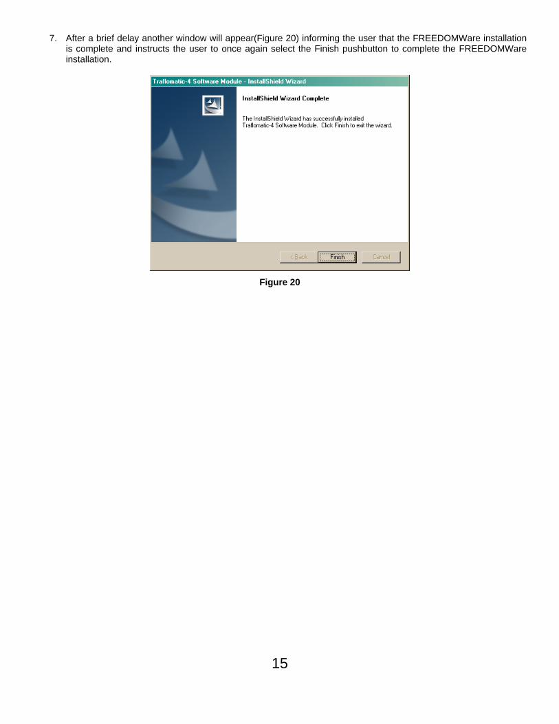
7. After a brief delay another window will appear(Figure 20) informing the user that the FREEDOMWare installation is complete and instructs the user to once again select the Finish pushbutton to complete the FREEDOMWare installation.
Figure 20

16
Installing the Security Key Drivers:
1. AT THIS TIME PLUG THE USB SECURITY KEY INTO THE USB PORT ON THE NOTEBOOK PC.
2. Shortly after connecting the USB Security Key for the first time, a Found New Hardware Wizard will appear. Figure 21. The user should click on the circle beside No, not this time so that a Black Dot appears in the circle. Once this has been selected the user should select the Next pushbutton with the PC’s pointing device in order to continue the Security Key Setup.
Figure 21

17
3. The next window in the Security Key Setup informs the user that the wizard will help install the necessary software for USB KEY. Refer to Figure 22. In this window make sure the circle beside Install the software automatically (Recommended) has a black dot. With the Black Dot in place in the desired location, select the Next pushbutton to continue with the Security Key Installation.
Figure 22
4. The installation will continue with installing the drivers for the security. While this installation is proceeding, a window will pop up notifying the user that the software being installed for the USB KEY has not passed Windows Logo testing to verify its compatibility with Windows XP. Refer to Figure 23. This window gives the user the options of Continue Anyway or STOP Installation. At this time, the user MUST select the pushbutton labeled Continue Anyway in order to successfully install the drivers for the USB Security Key.
Figure 23
18
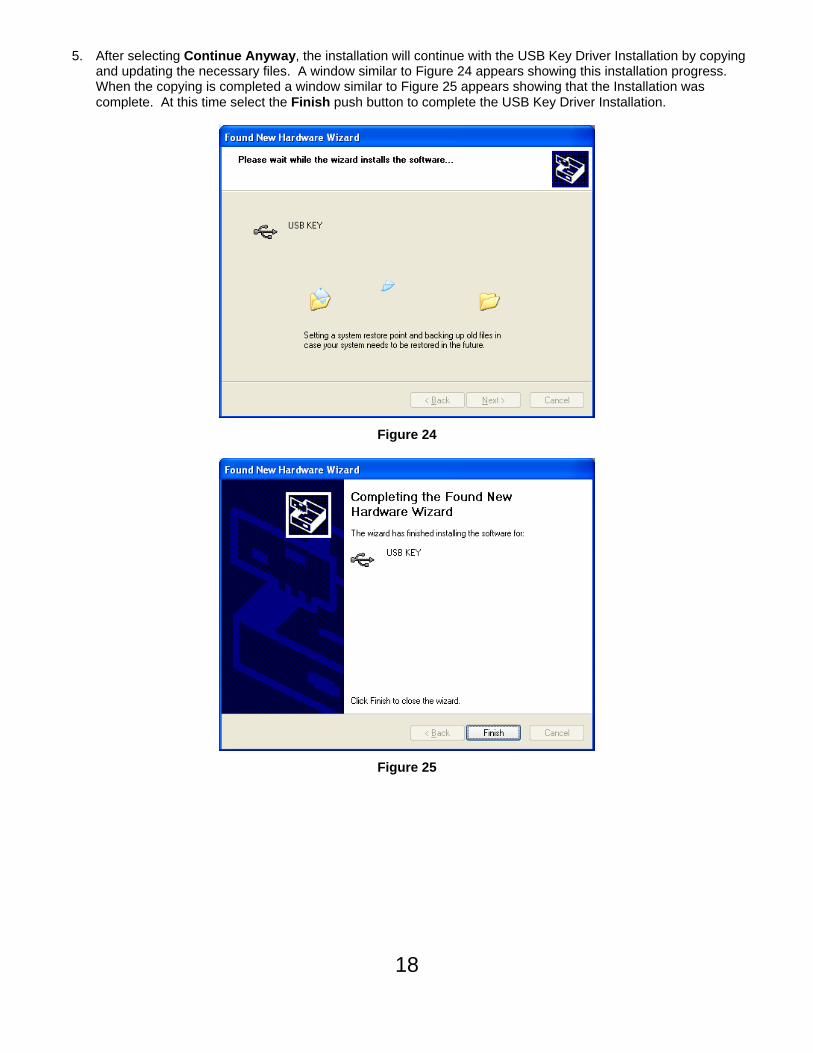
5. After selecting Continue Anyway, the installation will continue with the USB Key Driver Installation by copying and updating the necessary files. A window similar to Figure 24 appears showing this installation progress. When the copying is completed a window similar to Figure 25 appears showing that the Installation was complete. At this time select the Finish push button to complete the USB Key Driver Installation.
Figure 24
Figure 25

19
Executing the FREEDOM Tool Shell Program:
The start up procedure of the WORLD electronics’ FREEDOM Tool is described as follows:
1. Make sure the security key is installed on the USB port of the computer.
2. From the Microsoft Windows Desktop Screen select the FREEDOM Tool Icon by using the pointing device to position the cursor directly over the FREEDOM Tool Icon and double clicking the pointing device button. Refer to Figure 26.
Figure 26

20
3. Double clicking the FREEDOM Tool Icon will run the main FREEDOM Tool Application software. This software allows the user to select the various FREEDOMWare module that WORLD electronics has available. Refer to Figure 27.
Figure 27
NOTE: Only installed FREEDOMWare software will run. If the module selected is not installed a window will appear as in Figure 28 informing the user that the Module is not installed and to contact WORLD electronics. If this window appears and the software was purchased from WORLD electronics, then contact a member of WORLD electronics’ technical support staff. If the software was not purchased, it can be purchased by contacting WORLD electronics’ Sales Staff. The contact information on both of these departments can be found on Page 2 of this manual.
Figure 28
4. In order to run the Traflomatic Software Module the user would need to select Dover from the menu. Refer to Figure 29. After Dover is selected the user is presented with choices of USB, Serial Port, DMC File Utility, Traflomatic III and Traflomatic IV.
Figure 29
5. The next item to be selected in order to run the Traflomatic-III or Traflomatic-IV Software Module is their respectively named menu choices as shown in Figure 29 above. At this time position the Notebook PC’s pointing device over top of the desired controller choice and click one time. If the module is installed, the software will begin running at this time.

21
Getting Started:
Starting the Traflomatic-III or Traflomatic-IV Software Module:
1. With the FREEDOM Tool selection window open, position the cursor directly over the appropriate system manufacturer menu item selection, and single click the pointing device button. This causes a drop down list to appear giving the user a choice of controllers. Refer to Figure 30.
Figure 30
2. To open the Traflomatic-IV Software module, position the cursor over the menu choice Traflomatic-IV. If Traflomatic-III is desired, position the cursor over the menu choice Traflomatic-III. When the cursor is positioned over the desired controller, single click with the pointing device button.
3. The About: Security Key Information window will be displayed as in Figure 31, if the correct security key has been determined to be installed. A successful access to the security key is indicated by a green box surrounding the picture of the security key device along with the designation PASSED located in the field Software Security :. Other information contained within this window is: contact information for contacting WORLD electronics technical support, revision information on the current software, and a final instruction to connect the communication cable to the elevator and logon to the elevator. In order to continue using the Traflomatic software module position the cursor over the OK and single click with the pointing device button. When OK is selected, the main window of the Traflomatic Software Module will open.

22
Figure 31
In the event that the security key has not been installed or there is a problem with the installed key, the About: Security Key Information window will open showing a picture of the security key with a red box around it. The text of this window will tell the user a security key error has been detected and it will show the actual error number in the field labeled AUTHORIZATION ERROR:. Refer to Figure 32. To close this window, the user must position the cursor over the OK and single click with the pointing device button. This causes the FREEDOM Tool software to terminate execution and return to the Windows Desktop.
Figure 32
In the case that the security key is good, a window as seen in Figure 33 will appear. If the elevator controller power is already turned on, the screen will update after a couple seconds requesting the user to enter a password. Refer to Figure 34. Otherwise, turn the controller power to the ON position. As the controller boots

23
itself up, the screen will update showing several diagnostic tests prior to requesting the user to enter password. Refer to Figure 35.
Figure 33
Figure 34

24
When prompted to Enter Password>, the user must enter the password to access the service tool that resides within the elevator controller. This password can be entered by either typing it directly into the screen or by selecting Password from the FREEDOM Tool’s Menu and then following the given directions. It is important to note that the standard password for the Traflomatic elevator systems is the text DOVER TIII in all capital letters.
GENERAL DESCRIPTION – Traflomatic-III and IV
After getting past the security key check in the start-up procedure of the FREEDOM Tool, the main window appears similar to Figure 36. The main window as viewed in Figure 36 can be broken into four (4) sections. These sections are: The Menu, The Feature Bar, The Definition Bar, and the Terminal Window. These four (4) sections are described as follows:
Figure 35

25
The Menu: Located at the top of the main window is the Menu. Selections given on the menu are File,
Password, Commands, Transfer, and About.
File: The first selection found on the menu is File. In order to access a feature/command under the File menu item, the user would need to maneuver the mouse pointer over the word File and click one time with the mouse button. This will drop down the File menu choice revealing Port Set-Up, Connect, Disconnect, and Exit. Refer to Figure 37.
Figure 36
Port Set-Up: Port Set-Up opens the Communication Port Set-Up Window (Figure 38) that allows the user to choose what serial port assignment they wish to communicate along with the Baud rate at which to communicate. Instructions given on the screen tell the user to first select the communication port the computer is communicating with and then to select OK to accept the new setting and continue or Cancel to ignore the selected settings and continue using the FREEDOM Tool. Two drop down boxes are provided to the user in this window to select the desired Port and communication rate(Baud). To change a selection in one of these, move the mouse pointer over top of the down arrow beside the desired box and click one time. This procedure will drop down a list in which the user can then select their desired choice. When the desired choice is made, by clicking the mouse button one time, the selection will be shown in the text field of the drop-down list. It is important to note that entering this window will cause the FREEDOM Tool to close its connection with the elevator system. When this window is closed the FREEDOM Tool will re-establish communications with the elevator controller, but the user will be requested to re-enter the password.
Figure 37

26
Figure 38
Figure 39
Connect: The Connect menu choice will be disabled(grey) during normal operation of the FREEDOM Tool. If this menu item is active, the user would select it to initialize communication between the elevator controller and the FREEDOM Tool. Shortly after selecting this menu choice the Terminal Window will update requesting that the user Enter Password>.
Disconnect: The Disconnect choice found under the File menu terminates the communication between the FREEDOM Tool and the Elevator Controller.
Exit: Selecting Exit will shut down the FREEDOM Tool software and return the user to the FREEDOM Tool Shell program where the user can make a new selection of elevator controller to diagnose.

27
Password: Selecting Password from the Menu opens a window that allows the user to enter a password to log onto the Traflomatic controller. When Password is selected, a window similar to Figure 41 will appear. Note that the Password field in this window is DOVER TIII. DOVER TIII is the default password for both the Traflomatic-III and Traflomatic-IV elevator control systems. If the user knows of a different password for the connected controller, the user needs to click on the field containing DOVER TIII and then type in the desired password. After the desired password appears in the Password field, select OK to have it transmitted to the connected elevator controller. The user does not need to select Password in order to get the password transmitted to the elevator system. It can be entered directly through the Terminal Window. As the password is being entered in the Terminal Window, it will appear as stars (*). An unsuccessful password transmittal will be responded to with the text Must Enter Password. Also anything typed in after using an improper password will still appear as stars (*).
Figure 40
Commands: Selecting Commands from the Menu presents the user with several command choices that are transmitted directly to the connected elevator controller. These choices are: ATU – Auto Tune, EDS – Set Emergency Dispatch Service Floors, EDSD – Display Emergency Dispatch Service Floors, FDCI – Initialize Freight Door Open/Close Type, FLTP – PMI Faults, PAR – Display Parameters, RES – Initialize EEPROM, RRS – Reset Run Time Statistics, RUT – Reset Power-Up Counter, STM – Set-Up Mode, TFR – Reset Tachometer Fault, TMP – Temporary Operation (Construction). The Commands menu choice gives the FREEDOM Tool user the ability to quickly send these commands to the elevator controller. Many of these commands can be found in other section of the FREEDOM Tool.
Figure 41

28
Transfer: The FREEDOM Tool has features that allow the user to restore and backup information to the elevator controller. This operation can be performed through the Transfer menu choice. When Transfer is selected by the user it is apparent that the user can choose one of two choices. Refer to Figure 43.
Figure 42
These two choices perform the tasks necessary to save and restore elevator parameters. They are presented to the user in the form of Save Elevator Parameters and Restore Elevator Parameters respectively on the Transfer submenu.
Save Elevator Parameters: After selecting Save Elevator Parameters from the Transfer submenu, the user is requested to enter a filename in which to save the current elevators parameters. This is done through a standard Windows dialog titled Received File. Refer to Figure 44.
Figure 43
After typing the filename into the field marked File name the user only needs to select the Save push button to begin the save procedure for the Traflomatic elevator controller. This procedure starts by sending to the controller the command PARD. The elevator will respond with the text Enter Download Mode. Shortly after this appears, parameters will begin appearing within the Terminal Window. Refer to Figure 45.

29
Figure 44
Also note that the Definition Bar(Lower section of Main Window) changes to show a pushbutton and a bar graph. The bar graph will cycle as text is received by the FREEDOM Tool. This is an indicator that communication is occurring. After the elevator controller has completed downloading the job data to the FREEDOM Tool, a prompt showing the letter G and the group number followed by a C and the car number and then the > symbol will appear. At this time the user would select the End Save pushbutton to complete the save procedure.
Restore Elevator Parameters: In order to upload parameter values from the FREEDOM Tool to the elevator controller, the tool user would select Restore Elevator Parameters from the Transfer submenu. The first window to appear when the Restore Elevator Parameters menu selection is selected is a window similar to the one seen in Figure 46.
Figure 45

30
The Send File window is a standard Windows dialog box that allows the user to select a file from directory within the notebook PC’s disk drive system. When the desired file is found, click on it one time so that its name appears in the File name field. To continue with the restore procedure, click one time on the Open pushbutton. Next, a dialog box for each adjustment will appear asking the user whether to restore the selected adjustment. Refer to Figure 47.
Figure 46
If the user desires to restore that adjustment, the Yes pushbutton should be selected. Otherwise the user should select the No pushbutton. These Restore Variable dialog boxes will keep appearing until all of the adjustments within the restore file have been accessed. As Yes is selected, the text seen within the Restore Variable dialog box should appear on Terminal Window.
Definition Bar: Located on the Main Window are three functional areas that change depending on what mode of the tool the user is in. The first of these areas is located at the very bottom of the Main Window. This area is called the Definition Bar. Figure 48 shows the Definition Bar for the Transfer mode of the FREEDOM Tool. The Definition Bar aids the user by giving more specific information and possibly additional options for the selected feature.
Figure 47

31
Terminal Window: The large, white area located between the Feature and Definition Bars of the FREEDOM Tool Main Window is called the Terminal Window. Please refer to Figure 49. The Terminal Window is where the communication that occurs between the elevator and the tool is presented to the user. The user can transmit information to the elevator controller by selecting different adjustments/choices located upon the Feature Bar and the Definition Bar. A special feature of the Terminal Window is the ability to review the previous communications with the elevator controller during the current login session. On the right hand side of the Terminal Window is a scroll bar with two arrows(one for up and one for down). To scroll through the communication, the user simply clicks on these arrows with the PC’s pointing device and the communications will scroll on the Terminal Window. The Terminal Window acts just like the OEM’s original service tool where a terminal emulation program and instruction manual was used to adjust/diagnose the connected elevator system. If the user knows the commands for a T-III/T-IV or has a reference manual, the Terminal Window can be used to directly enter those commands to the elevator controller.
Figure 48

32
The Feature Bar
Change Elevator: n the terminal mode of the FREEDOM Tool software the user can elect to change what elevator controller they are communicating with by simply pressing the Esc pushbutton on their keyboard. Doing this will bring up a G#C#> prompt. At this point the user needs to type in the group number and car number of the controller they desire to communicate with and then press the Enter key. The Change Elevator pushbutton on the Feature Bar also does this operation but in a graphical environment. When the Change Elevator pushbutton is selected a window similar to the one seen in Figure 50 appears.
Figure 49
The current connection is shown via the highlighted radio buttons for Car# and Group#. To change which Car/Group controller the FREEDOM Tool is communicating, the user simply clicks on the circle beside the desired connection and press the OK pushbutton at the bottom of the window. The Cancel pushbutton is used to cancel this operation and return back to the previous connection.
Car Mode: A check mark in the box located beside Car Mode informs the user that the FREEDOM Tool’s Feature and Definition Bars are setup for communicating with a car controller. When the user places a check in this box by clicking with the PC’s pointing device, the Definition Bar updates reminding the user to select a specific car within the group(s) that the user wants to communicate with by choosing the pushbutton labeled Change Elevator. Refer to Figure 51.
Figure 50

33
Group Mode: If a check mark is placed or located in the box beside Group Mode, the FREEDOM Tool is setup to communicate directly with a group controller. The Feature Bar would update to show choices of Reference, Car/Group, Hall Calls, Scan Assignment, Code Blue, Init. Security, and Lockouts. Along with adding these items, the Adjustment, Job Info, Timers, CSW, and Displays list would update to reflect choices specifically for the group controller part of the FREEDOM Tool. After Group Mode is selected, the Definition Bar updates to remind the user that Change Elevator must be selected in order to properly communicate with the designated group controller. Please refer to Figure 52.
Figure 51
NOTE: On a Traflomatic-III the physical connection of the communication cable must be changed to the desired Group/Car Controller to diagnose/adjust, in addition to selecting the Car/Group checkbox.
Selection Bar: Located below the pushbuttons for Adjustments, Timers, Job Info, Displays, and CSW is a drop down list that contains the items specific to the selected diagnostic mode. When any of the above mentioned pushbuttons is selected this Selection Bar list will update for that particular section of the FREEDOM Tool. To select a specific item, click on the down arrow to the left of this Selection Bar. This will drop down the list. Next scroll up and down through the list until the desired item is found by using the up and down arrows found to the right of the drop down list. Once the desired item is found click on it one time using the PC’s pointing device. This will transmit the appropriate acronym to the elevator controller and also set up the Definition Bar for the selected item. Please refer to Figure 53.
Figure 52

34
Adjustments: Adjustments are commands that change how a particular car will operate. These usually have an upper and lower range along with a default value. Adjustments can be found in both the Car and Group modes of the FREEDOM Tool. When the Adjustment button is selected, the list found within the Selection Bar will show the available adjustments for the selected Car/Group controller. Please refer to Figure 54 for an example of the FREEDOM Tool main window after an adjustment has been selected from the adjustment list.
Figure 53
Every selected adjustment has specific Definition Bar information that goes with it. For an adjustment the typical Definition Bar would contain the selected adjustment’s name, the acronym for that adjustment, and an Description Pane defining the Default Value, Lower Limit, Upper Limit, and the incremental value for the selected adjustment. Also located within the adjustments Definition Bar is an edit field where the user can type in the desired new value for the adjustment. To use this edit feature the user would click one time in the white box located above the Change Value pushbutton. This will cause a flashing bar to appear within this edit window. Next the user would type in the new desired value and then click the Change Value pushbutton one time with the PC’s pointing device. Shortly after Change Value is selected the Terminal Window would show the communication occurring between the FREEDOM Tool and the elevator controller and then the result. If any error occurred while entering the new value to the elevator controller, it would also appear within the Terminal Window.

35
Job Info: The Traflomatic elevator controllers have Job Specific data that can be viewed. Selecting the Job Info pushbutton, while in either Group or Car mode of the FREEDOM Tool, will change the drop down list underneath the Job Info pushbutton. The dropdown list will update with the names of viewable job parameters for the connected elevator control system. Selecting one of these parameters located on the dropdown list while the Job Info button is pressed will cause the FREEDOM Tool to transmit the appropriate command to the elevator controller so the user can view that parameters setting. This communication can be viewed within the Terminal Window. Along with the terminal window showing the communication between the FREEDOM Tool and elevator controller, the Definition Bar will update showing additional information for the selected job parameter. Please refer to figure 55.
Figure 54

36
Timers: Both the Group and Car Modes of the Traflomatic-III and IV elevator control systems have timer adjustments. Timer adjustments are any adjustment that can be associated with a time. This can include how long a car will remain idle before taking itself out of service, how long the doors stay open before closing, among many other things. As with Adjustments and Job Info, Timers will have information displayed for each individual timer in the Definition Bar of the FREEDOM Tool. Please refer to Figure 56.
Figure 55
The Timers Definition Bar will include the name of the Timer, the acronym used by the elevator controller for the Timer, its upper and lower values, the default value, and what the increment is for the timer adjustment. Just like the Adjustments Definition Bar, the Timers have the ability to be change. This can be done through direct entry in the Terminal Window or by typing the desired value into the white edit box located on the Definition Bar and then selecting the Change Value push button.
CSW: The Traflomatic-III and IV elevator control systems have many features that can be turned on or off through what is called a Control Status Word(CSW). A CSW is a 16 bit number where each of the bits represents a feature of the elevator that can be switched on or off. The CSW is displayed on the terminal window as a 1 to 4 digit sequence followed by the letter H. Refer to Figure 57. This letter H indicates that the value being observed is a hexadecimal number. Each digit in a hexadecimal sequence represents a series of 4 individual bits. Use Table 1 and the following example to determine which bits in the CSW are active and which are inactive.

37
Example of converting CSW value to SET and RESET features:
CSW = A7F3H
The number can be expressed as WXYZH, where W, X, Y, and Z each represent 4 bits of the control status word. W would represent bits 15, 14, 13, and 12. X would represent bits 11, 10, 9, and 8. Y would represent bits 7, 6, 5, and 4. Z would represent bits 3, 2, 1, and 0. The H indicates the number is in hexadecimal format.
Position Bit
Value Bit
Value Bit
Value Bit
Value W 15 14 13 12
X 11 10 9 8 Y 7 6 5 4 Z 3 2 1 0 0 0 0 0 0 1 0 0 0 1 2 0 0 1 0 3 0 0 1 1 4 0 1 0 0 5 0 1 0 1 6 0 1 1 0 7 0 1 1 1 8 1 0 0 0 9 1 0 0 1 A 1 0 1 0 B 1 0 1 1 C 1 1 0 0 D 1 1 0 1 E 1 1 1 0 F 1 1 1 1
Table 1
Looking at the Example the value at position W is A. The value at position X is 7. The value at position Y is F, and the value at position Z is 3. Using Table 1 with regards to the example it can be said that for the selected CSW Bits 15, 13, 10, 9, 8, 7, 6, 5, 4, 1, and 0 are SET(1). The remaining bits 14, 12, 11, 3, and 2 would be RESET(0)

38
Figure 56
When a CSW is selected, the Definition Bar updates with information and features specific for a CSW, and the selected CSW request is sent to the elevator controller via the Terminal Window. The Definition Bar will show the name of the selected CSW, a SET pushbutton, a CLEAR pushbutton, an ALL pushbutton, a bit selection box to select bits 0 through 15, and a description pane where each individual bit is defined for its SET or RESET state.
SET: The SET pushbutton will send a command to the elevator controller requesting that the selected bit be updated to a SET(1) state. This is similar to the BITS command. In the Terminal Window, the user would see the command BITS followed by the CSW number and the bit number the user desired to change. The bit number will be the bit selected in the Bit Selection Box.
CLEAR: Pressing the CLEAR pushbutton will command the elevator to set the state of the selected CSW bit to a RESET(0) state. This is similar to sending a BITR command to the elevator controller. On the Terminal Window the user would see the command BITR followed by the CSW number and then the bit selected in the Bit Selection Box.
Bit Selection Box: This box is used to select a specific bit within the CSW for the FREEDOM Tool to focus on. When one of the numbers from 0 to 15 is selected the description pane found to the right of Bit Selection Box will update giving information on the selected bit. The highlighted bit in this box is the bit that the FREEDOM Tool is currently focused upon.
Description Pane: The Description Pane displays specific information for the SET and RESET state for the current focus bit selected in the Bit Selection Box.

39
ALL: The ALL pushbutton sends a command to the Elevator Controller requesting that the individual bit status for all CSW’s be displayed within the Terminal Window. Figure 58, shown below, depicts the Terminal Window after the ALL pushbutton has been pressed. The FREEDOM Tool will transmit the command BITD to the elevator controller. The elevator will respond with a table showing the individual bit numbers across the top and the CSW Numbers down the Left side of the table. Within the Table are individual 1’s and 0’s (Bits) that represent the current state of each CSW bit. A 1 on this Table indicates the bit is SET while a 0 indicates the bit is in a RESET state.
Figure 57

40
Displays: Displays are used to assist in diagnosing certain elevator controller functions in regards to elevator operation status. When the Displays selection button is pressed the Selection Bar updates to show the different display features of the T-III and/or T-IV elevator control systems. Figure 59 shows the FREEDOM Tool main window after a display Item has been selected from the Selection Bar.
Figure 58
When a display Item is selected from the Selection Bar, the Definition Bar updates to show specific information on the Display item selected. Among the things found within the Definition Bar for a display is the name of the display selected, the signal acronym for the display which will be transmitted to the elevator controller, and a description pane that will have text defining items within the display selected. Shortly after selecting the Displays, the Terminal Window will update showing the display acronym and then the response from the elevator controller.

41
Figure 59
FAULTS: A log of up to 23 faults is stored within the elevator controller at any single time. This fault log can be viewed by selecting the FAULTS pushbutton located underneath the Selection Box. The FAULTS pushbutton sends the FLT command to the elevator controller for the retrieval of the fault log. Referring to Figure 60, the Fault Log is shown within the Terminal Window after FLT has been transmitted to the elevator system. The faults in the log are numbered 0 through 23 with 0 being the most recent fault and 23 being the oldest fault on the log. Each fault is logged with a fault code and a number of times the fault has occurred. When FAULTS is selected on the Feature Bar, the Definition Bar is updated to provide the user assistance in viewing the faults. Located on the Definition Bar is a scrolling list that contains the known faults for a Traflomatic-III and Traflomatic-IV elevator controller. To view what any fault means, the user simply finds the fault code within this list by scrolling up or down through it and selecting the fault code. In the fault log, the fault code is the number that immediately follows the = symbol. When a fault code has been selected the description of the fault will appear to the right of the Definition Bar in the area labeled Description. It is important to note that only the description of the fault will appear here. WORLD electronics cannot provide technical information in print form on causes of any fault codes. Also located on the Definition Bar are two pushbuttons. These buttons are RESET and DETAIL. They are described as follows:
RESET: The RESET pushbutton commands the FREEDOM Tool to transmit the reset fault command to the elevator controller. This will temporarily set all faults to the value 0 for No faults detected. If a fault check, after resetting the fault log, still shows some fault codes, then there are still faults within the elevator system and steps should be taken to correct those faults. If the fault log has all 24 faults assigned a 0 code, then there are no faults currently within the elevator system.
DETAIL: The DETAIL pushbutton sends the FLTN command to the elevator controller. When the elevator controller receives this command, it responds by showing a table as viewed in Figure 61.

42
The table shown in Figure 61 will show up to 5 of the most recent faults along with a time stamp of when they occurred. This time stamp is in the form of Days-Hours:Minutes:Seconds. Along with the time stamp, the table will give information on the Car’s Velocity(CVel) and the Demanded Velocity(DVel) when the fault occurred. Other information includes the Position(DPP), the Direction(D), and the type of Service(S#) of the car at the time of the fault.
Figure 60
SAVE: The SAVE pushbutton takes the current working parameters for the connected car and stores it within the EEPROM for the elevator controller. This save enables the value stored in EEPROM to be restored and keep the car running whenever a power interruption occurs to the elevator controller. This command saves all elevator operating parameters(Timers, Adjustments, CSW’s). The command sent to the elevator controller using the SAVE pushbutton is WRT. If the save was successful, the Terminal Window should show a response of WRT>>OK from the Elevator Controller in response to the WRT command.
RESTORE: Use the RESTORE pushbutton to transfer any parameter information from the EEPROM to working value for the connected elevator controller. The RESTORE pushbutton transmits a GET command to the connected elevator controller. When the RESTORE has successfully completed, the elevator controller responds with GET>>OK through the Terminal Window of the FREEDOM Tool.
UP 1 Floor: The Up 1 Floor pushbutton is used to transmit the elevator controller the command to have the car run 1 floor in the up direction. The actual command sent to the elevator controller through the Terminal Window is: STU. Upon receiving the Up 1 Floor command, the elevator controller will respond with: STU>>OK.

43
Down 1 Floor: The Down 1 Floor pushbutton transmits to the elevator controller the command to have the car run 1 floor in the down direction. The command sent by the FREEDOM Tool to the elevator controller to accomplish this is: STD. When the Run 1 Floor Down command has been received form the elevator controller, it will respond with: STD>>OK and then run the car down 1 Floor.
Auto Tune: On an elevator controller that is being used in conjunction with an SCR Drive, the SCR Drive can be commanded to Auto Tune itself by using the Auto Tune pushbutton from the Feature Bar. Figure 62 shows the Definition Bar as it is viewed after the Auto Tune pushbutton is selected.
Figure 61
The FREEDOM Tool instruct the user in the Definition Bar that if OK is selected, the loop contactors on the SCR drive will close and the drive will start tuning itself. The Definition Bar also states that the Inspect/Auto switch on the elevator controller cabinet must be in the Inspect position. To continue with the Auto Tune procedure, the user simply needs to press the OK pushbutton located on the left side of the Definition Bar. To cancel the Auto Tune procedure, select the CANCEL pushbutton located beneath the OK pushbutton within the Definition Bar. The command sent to the elevator controller via the FREEDOM Tool is: ATU. The elevator controller will respond with: Auto-Tune ON.
Automatic Set-Up: Automatic setup is used much like a hoistway setup is used in a Dover DMC-I hydraulic unit. The Automatic Set-Up feature allows the car to run Up through the hoistway at inspection speed while learning the digital position encoder counts for each landing’s leveling and position vane. When the Automatic Set-Up pushbutton is selected the Definition Bar updates as shown in Figure 63. The Definition Bar provides pushbuttons that are necessary for performing the Automatic Set-Up procedure as the user follows the directions. The directions for the Automatic Set-Up procedure are displayed within the description pane on the right side of the Definition Bar..
Figure 62
Note: The definition pane on the Definition Bar has a scroll bar attached to it. This means there are more instructions within the definition pane than can be displayed at one time. Please follow the instructions for the Automatic Set-Up procedure very carefully.

44
Set-Up Procedure (Refer to Figure 63)
1) Turn Door Switch on elevator controller cabinet to the OFF position.
2) Place a jumper on the bottom normal limit switch signal.
3) Turn the INSP/AUTO switch on the controller cabinet to the INSP position
4) Run the car on inspection so that the car is below the bottom landing
NOTE: The LU input should be active at this time.
Figure 63
Refer to Figure 64 for the following:
5) Place a jumper on the UP normal limit switch.
6) Place a jumper on the bottom final limit if the car is on the bottom final limit.
7) Press the Inspect Vel. pushbutton to send the command for setting the inspect velocity to 50 feet per minute to the elevator controller.
Figure 64
Refer to Figure 65 for the following:
8) Click on the Auto-Set-Up pushbutton on the left of the Definition Bar to enter into the automatic set-up mode.
9) Press the UP button on the controller cabinet until the car travels past the top landing and LD becomes active.
NOTE: The bottom final limit jumper should be removed before the car reaches the top of the hoistway. When the Car finishes the Automatic Set-Up mode the Terminal Window should update showing NORMAL MODE.
Figure 65
Refer to Figure 66 for the following:
10) Place a jumper on the top final limit signal and run the car off of the top final limit using the DOWN push button on the elevator controller cabinet.

45
Figure 66
11) To review the floor table, select the pushbutton labeled Floor Count on the left side of the Definition Bar. Each floor should have a count value associated with it. The first floor’s value should be 10,045 +/- 5 counts.
Figure 67
Refer to Figure 68 for the following.
12) Select the SAVE pushbutton on the Feature Bar.
13) Remove the jumpers placed on the top final limit and up normal limit.
14) Turn elevator controller CPU power switch to OFF and then back to ON.
15) Log back onto the elevator by entering the Password. This can be done by selecting Password on the FREEDOM Tool’s menu or by entering it directly in the Terminal Window.
16) Select EXIT on the left side of the Definition Bar to exit the Automatic Set-Up procedure.

46
System Test: Selecting the System Test pushbutton will update the Definition Bar so that the user can select any one of the seven systems tests for the Traflomatic-III and Traflomatic-IV elevator control systems. The tests available are NTSD, ETSD/L, Car Buffer, CWT Buffer, Governor, Car Safety, and CWT Safety. Refer to Figure 69. Select any one of the test pushbuttons located on the Definition Bar to perform that test. The procedure for the selected test should appear in the description pane on the right side of the Definition Bar.
Figure 68
Security Selecting Security form the Feature Bar sets the FREEDOM Tool in a mode that works specifically with the elevator controller’s security features. When the Security pushbutton is pressed, the Definition Bar updates as shown in Figure 70.
Figure 69
The Definition Bar gives the user three pushbutton options: Type 9, CODE, and INITIALIZE. The INITIALIZE pushbutton sends a command(SSI) to the elevator controller that initializes the security settings for the controller. The operation of the Type 9 and CODE pushbuttons are described as follows:
Type 9 Selecting Type 9 sets up the Definition Bar so that the Type 9 Security service can be programmed for the elevator controller. When Type 9 is selected, pushbuttons such as PROGRAM A,

47
PROGRAM B, FRONT, REAR, SECURE, UNSECURE, and CHANGE appear on the Definition Bar. A list box of floor numbers also appears near the center of the Definition Bar to assist the user with setting the security floor. The description pane on the right side of the Definition Bar is the instructions for setting up the security information. It has a scroll bar attached to it, indicating that there is more text within the description pane than can be viewed at one time. To view all of the text within the description pane the user needs to click on the up and down arrows located to the right side of the description pane. Refer to Figure 71.
Figure 70
CODE The CODE pushbutton changes the Definition Bar to a mode where the user can set up the Car Call Code Entry function. Refer to Figure 72. The Code Entry function is where the user can gain access to a landing by entering a code using the Car Call pushbuttons on the Car Panel.
Figure 71
Looking at Figure 72 there are several pushbuttons that appear when the CODE pushbutton is selected. The CHANGE pushbutton is used to change the value of any of the selected buttons on the Definition Bar. The COUNT pushbutton(CEC) allows the user to view and/or change the value representing how many digits are in the Entry Code. The TIME pushbutton(CET) allows the user to view and set the allotted time for the complete entry to occur once the first code button has been selected. The code pushbuttons 0 through 9(CE0 – CE9) represent the code value sent to the elevator using the assigned Car Call pushbutton in the car panel. For example: if Code 0 has the value 5, the 5th floor Car Call button in the car panel would transmit a 0 as part of the Call Entry Code when pushed.
Terminal Back-Up The Terminal Back-Up pushbutton changes the layout of the Definition Bar to focus on the tests for the Terminal Back-Up system of the Traflomatic-IV elevator controller. When selected, the Terminal Back-Up function of the FREEDOM Tool gives the user the choice to operate any of four Terminal System test. These tests can be selected through four check boxes labeled: ETSD/L(TBSE), NTSD(TBSN), Total System(TBS), and System Save(TBSS). Refer to Figure 73.
Figure 72
When one of these tests is selected, by placing a check in the box beside the test name, the description area on the right side of the Definition Bar updates to give a description of what the test will do. In

48
addition, the selected test’s command will be transmitted to the elevator system through the terminal window.
Load Weigher: Selecting the Load weigher pushbutton on the Feature Bar changes the controls that reside on the Definition Bar so the focus is placed upon the Digital Loadweigher system of the Traflomatic-III / IV elevator control system. Figure 74 shows the Definition Bar as it would appear after the Load Weigher pushbutton has been selected.
Figure 73
The Definition Bar as set by the Load Weigher pushbutton option gives the user the ability to view the Loadweigher parameters along with changing the values for Capacity, Shutdown, Warning, Bypass, Dispatch, Priority Lowering, and Anti-Nuisance. Also located on the Load Weigher Definition Bar are two pushbuttons for learning the car at a Full Load and No Load condition. When any of these pushbuttons are selected the description pane on the right side of the Definition Bar updates to give specific information on the selected button. A Change pushbutton will appear along with a white edit box, when the selected function has the ability to have its value changed. To change a functions value, simply type the desired value into the white edit box and then select the edit pushbutton. Refer to Figure 75.
Figure 74
NTS: The functions available to diagnose and adjust the Normal Terminal System can be found by selecting the NTS pushbutton on the FREEDOM Tool’s feature bar. Selecting NTS from the Feature Bar will setup the Definition Bar as shown in Figure 76, allowing the user to select from several adjustment and display items specific to the NTS system.
Figure 75
Items found on the NTS Definition Bar are adjustments for Percent Margin(NTM), Lvl. Speed(NTS4), Low Error Gain(NTS2), Rate Limit(NTS5), Check Points(MXV), and FPM Offset(NTO). When any of these items is selected, the description pane to the right of the Definition Bar updates to show specific information on the selected adjustment. In addition, a white edit box and a Change Value pushbutton appear giving the user the ability to change the value of the selected adjustment. The NTS Definition Bar also has a button for Initializing(NTSI) the NTS system parameters and two buttons for viewing information on the System Top(NTST) and System Bottom(NTSB).

49
ETS: The ETS pushbutton enables the user to setup the elevator’s Emergency Terminal System. When the ETS pushbutton is selected, the Definition Bar at the bottom of the FREEDOM Tool’s main window updates as shown in Figure 77. Located on the ETS Definition Bar are pushbuttons for displaying ETS Faults(ETSF), ETS System Bottom Information(ETSB), and ETS System Top Information(ETST). The Percent Margin(ETM) pushbutton is used to adjust the error added to velocity at which the ETS system trips. When Percent Margin is selected, a Change Value pushbutton along with a white edit box appears allowing the user to update this value. The Override(ETSO), Initialize(ETSI), and Save(ETSS) pushbutton perform their named functions upon the ETS parameters.
Figure 76
CALLS: Hall and Car Calls can be set, cleared, and viewed through the CALLS pushbutton of the Feature Bar. When the CALLS button is selected, the Definition Bar updates as shown in Figure 78. Located on the CALLS Definition Bar are several pushbuttons, a numerical listbox, and a description field. The three pushbuttons at the bottom of the CALLS Definition box cause the FREEDOM Tool to go into action in regards to CALLS.
Figure 77
These three pushbuttons labeled SET, CLEAR, and STATUS perform the following function:
SET: Use the SET pushbutton to set a car or Hall Call. Before the SET button can be pressed the user must decide what type of call they wish to set by selecting the Car Call or Hall Call pushbuttons. The Car Call, HALL Call, FRONT, UP, REAR, and DOWN pushbuttons are toggle buttons that hold their state of being up or pressed simply by being selected. The UP and DOWN buttons will not work in conjunction with the Car Call button.
Example: To set a 6th Landing Rear Car Call: (Refer to Figure 79)
1) Select Car Call
2) Select REAR
3) Select the number 6 on the Numerical listbox
4) Select the SET pushbutton. The type of Call entered should appear in the description pane to the right. Refer to Figure 80.
Figure 78

50
Figure 79
CLEAR: The CLEAR pushbutton works with the Car Call and Hall Call pushbutton on the Definition Bar. To clear a Car Call(RCC) the Car Call button should be selected prior to selecting the CLEAR pushbutton. A Front Hall Call(RHC) is cleared by selecting the Hall Call and FRONT pushbuttons followed by pressing the CLEAR pushbutton. A Rear Hall Call(RRH) would be reset by selecting the REAR pushbutton instead of the FRONT pushbutton in the prior described method for resetting hall calls. When reset, the description pane to the right, on the description bar, will update informing the user to the reset performed.
STATUS: To check on the status of Hall and Car Calls for the connected elevator controller, the user would use the STATUS pushbutton found on the CALLS Definition Bar. The status of Car Calls(CCS) is checked by selecting the Car Call pushbutton and then selecting STATUS. The elevator controller will respond to the FREEDOM Tool’s request as shown in Figure 81.
Figure 80
The response by the elevator is a hexadecimal number. The meaning of this response can be determined by looking up the value in the table located within the description pane of the Definition Bar. In the case of Figure 81, a response value of 0H from the elevator controller indicates that there were no car calls registered. A status check of hall calls would require the user to 1) select the Hall Call pushbutton, 2) select UP(UCS) or DOWN(DCS), and 3) select the STATUS pushbutton.

51
Lockouts: The Lockouts pushbutton on the Feature Bar enables the user to set lockouts for car calls in the connected elevator controller. Figure 82 shows the Definition Bar as it appears after the Lockouts pushbutton is selected with the PC’s pointing device.
Figure 81
Normal and DMS Software lockouts can be set using the FREEDOM Tool. DMS Software Lockouts are performed when the user selects the DMS pushbutton on the Definition Bar along with the other settings on the Definition Bar. Other pushbuttons made available to the user in regards to lockouts on the Definition Bar are: FRONT, REAR, SECURE, UNSECURE, and CHANGE. The Definition Bar also contains a numerical list box for the floor numbers and a description area. To set or clear a specific floor lockout the user does the following:
1) For a DMS Lockout select the DMS pushbutton, otherwise leave it unpressed.
2) Select FRONT or REAR. Both can’t be set at the same time.
3) Select SECURE to enable the lockout or CLEAR to remove the lockout.
4) Select the landing number from the numerical listbox.
5) Select the CHANGE pushbutton to transmit it to the elevator system.
6) The terminal window should have communication from the elevator system that says, These floors are secured: followed by the floor numbers that are secured.
REPEAT: Many displays can have data that is updated as the car runs through the hoistway. Rather than continuously select the display from the menu, the REPEAT pushbutton is used to automatically send the communication to the elevator system one time every second. To enable this feature of the FREEDOM Tool, the user needs to select the REPEAT pushbutton on the Feature button so that it is in its pressed state. To turn this off, select the REPEAT pushbutton so that it is no longer in its selected state.
Reference: Group Mode Only In the Group Mode of the FREEDOM Tool, there are adjustments, displays, and functions that are targeted for every car within the group. There are also adjustments that will affect specific cars within the group. The current Reference elevator for the group mode is found in the window immediately to the right of the Reference pushbutton. This window will have the value of 0 or will be blank if the reference elevator is the group system, otherwise it will have a number of a specific car. Refer to Figure 83 to see an example of the Reference pushbutton and reference window located on the Feature Bar of the FREEDOM Tool.
Figure 82
52
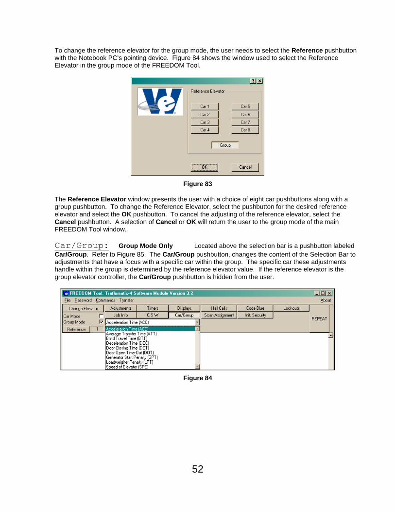
To change the reference elevator for the group mode, the user needs to select the Reference pushbutton with the Notebook PC’s pointing device. Figure 84 shows the window used to select the Reference Elevator in the group mode of the FREEDOM Tool.
Figure 83
The Reference Elevator window presents the user with a choice of eight car pushbuttons along with a group pushbutton. To change the Reference Elevator, select the pushbutton for the desired reference elevator and select the OK pushbutton. To cancel the adjusting of the reference elevator, select the Cancel pushbutton. A selection of Cancel or OK will return the user to the group mode of the main FREEDOM Tool window.
Car/Group: Group Mode Only Located above the selection bar is a pushbutton labeled Car/Group. Refer to Figure 85. The Car/Group pushbutton, changes the content of the Selection Bar to adjustments that have a focus with a specific car within the group. The specific car these adjustments handle within the group is determined by the reference elevator value. If the reference elevator is the group elevator controller, the Car/Group pushbutton is hidden from the user.
Figure 84

53
Scan Assignment: Group Mode Only The Scan Assignment pushbutton located on the Feature Bar of the FREEDOM Tool’s group mode, is used to view, reset, and alter the types of hall calls allowed at each landing for the connected group/car. The car the scan assignment is for is determined by the reference elevator setting. The Scan Assignment’s Definition Bar has pushbuttons for View Table(SCA), Alter Table(SCAA), and Initialize(SCAI). These can be seen in Figure 86.
Figure 85
View Table: The View Table pushbutton shows the current hall call table for the selected reference elevator. The command transmitted to the elevator controller is SCA. The elevator controller responds through the Terminal Window showing the command sent, the elevator the table is for, and the actual table. Refer to Figure 87. The description pane of the Definition Bar shows the meaning of the floor value displayed within the Terminal Window. All responses are in the form of a hexadecimal number, indicated by the H after the value for the floor. If a floor has a rear opening, the corresponding floor value would have two digits before the H. The first of these would be the value for the rear opening.
Figure 86

54
Alter Table: To change the hall call assignments for the reference elevator, the user of the FREEDOM Tool selects the Alter Table button from the Definition Bar while in the Scan Assignment function. Figure 88 shows the FREEDOM Tool’s main window after the Alter Table pushbutton is selected.
Figure 87
When Alter Table is selected, pushbuttons appear for having no calls assigned for a floor(FRONT NONE and REAR NONE), up only calls for a floor(FRONT UP and REAR UP), down calls only for a floor(FRONT DOWN and REAR DOWN), and both up and down assignments for a floor(FRONT BOTH and REAR BOTH). The user needs to make a selection among these pushbuttons and then select the SET pushbutton to make the desired setting to the floor. The floor being programmed is determined by the communication viewed in the Terminal Window. The assignments always begin with the bottom landing and proceed up through the top landing. A setting must be made to ALL landings.
Initialize: The Initialize button sends a command to the group controller having it set the hall call assignments to their default or initial value. The elevator controller will respond with OK if the initialization was successful.
55
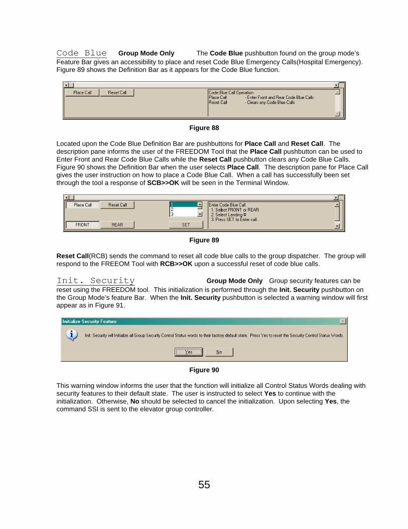
Code Blue Group Mode Only The Code Blue pushbutton found on the group mode’s Feature Bar gives an accessibility to place and reset Code Blue Emergency Calls(Hospital Emergency). Figure 89 shows the Definition Bar as it appears for the Code Blue function.
Figure 88
Located upon the Code Blue Definition Bar are pushbuttons for Place Call and Reset Call. The description pane informs the user of the FREEDOM Tool that the Place Call pushbutton can be used to Enter Front and Rear Code Blue Calls while the Reset Call pushbutton clears any Code Blue Calls. Figure 90 shows the Definition Bar when the user selects Place Call. The description pane for Place Call gives the user instruction on how to place a Code Blue Call. When a call has successfully been set through the tool a response of SCB>>OK will be seen in the Terminal Window.
Figure 89
Reset Call(RCB) sends the command to reset all code blue calls to the group dispatcher. The group will respond to the FREEOM Tool with RCB>>OK upon a successful reset of code blue calls.
Init. Security Group Mode Only Group security features can be reset using the FREEDOM tool. This initialization is performed through the Init. Security pushbutton on the Group Mode’s feature Bar. When the Init. Security pushbutton is selected a warning window will first appear as in Figure 91.
Figure 90
This warning window informs the user that the function will initialize all Control Status Words dealing with security features to their default state. The user is instructed to select Yes to continue with the initialization. Otherwise, No should be selected to cancel the initialization. Upon selecting Yes, the command SSI is sent to the elevator group controller.