T h e V e c to r-T h re a d Ar c h ite c tu...
12
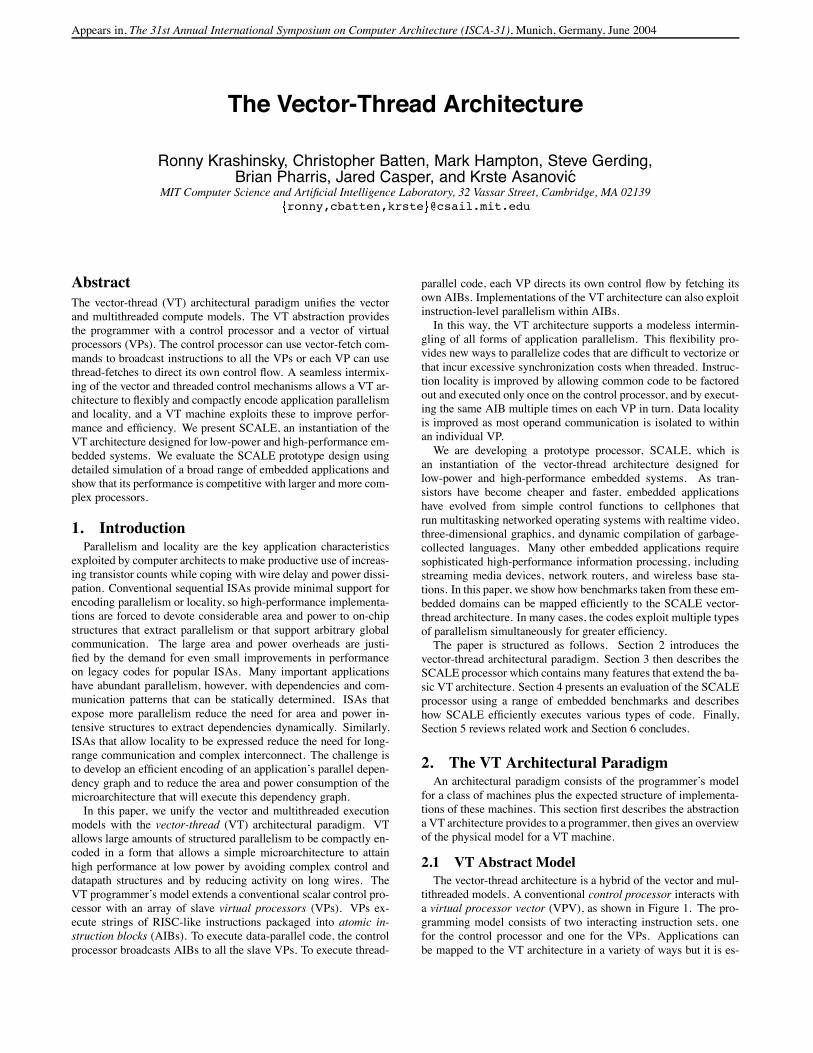
Appears in, The 31st Annual International Symposium on Computer Architecture (ISCA-31), Munich, Germany, June 2004 The Vector-Thread Architecture Ronny Krashinsky, Christopher Batten, Mark Hampton, Steve Gerding, Brian Pharris, Jared Casper, and Krste Asanovi´ c MIT Computer Science and Artificial Intelligence Laboratory, 32 Vassar Street, Cambridge, MA 02139 ronny,cbatten,krste @csail.mit.edu Abstract The vector-thread (VT) architectural paradigm unifies the vector and multithreaded compute models. The VT abstraction provides the programmer with a control processor and a vector of virtual processors (VPs). The control processor can use vector-fetch com- mands to broadcast instructions to all the VPs or each VP can use thread-fetches to direct its own control flow. A seamless intermix- ing of the vector and threaded control mechanisms allows a VT ar- chitecture to flexibly and compactly encode application parallelism and locality, and a VT machine exploits these to improve perfor- mance and efficiency. We present SCALE, an instantiation of the VT architecture designed for low-power and high-performance em- bedded systems. We evaluate the SCALE prototype design using detailed simulation of a broad range of embedded applications and show that its performance is competitive with larger and more com- plex processors. 1. Introduction Parallelism and locality are the key application characteristics exploited by computer architects to make productive use of increas- ing transistor counts while coping with wire delay and power dissi- pation. Conventional sequential ISAs provide minimal support for encoding parallelism or locality, so high-performance implementa- tions are forced to devote considerable area and power to on-chip structures that extract parallelism or that support arbitrary global communication. The large area and power overheads are justi- fied by the demand for even small improvements in performance on legacy codes for popular ISAs. Many important applications have abundant parallelism, however, with dependencies and com- munication patterns that can be statically determined. ISAs that expose more parallelism reduce the need for area and power in- tensive structures to extract dependencies dynamically. Similarly, ISAs that allow locality to be expressed reduce the need for long- range communication and complex interconnect. The challenge is to develop an efficient encoding of an application’s parallel depen- dency graph and to reduce the area and power consumption of the microarchitecture that will execute this dependency graph. In this paper, we unify the vector and multithreaded execution models with the vector-thread (VT) architectural paradigm. VT allows large amounts of structured parallelism to be compactly en- coded in a form that allows a simple microarchitecture to attain high performance at low power by avoiding complex control and datapath structures and by reducing activity on long wires. The VT programmer’s model extends a conventional scalar control pro- cessor with an array of slave virtual processors (VPs). VPs ex- ecute strings of RISC-like instructions packaged into atomic in- struction blocks (AIBs). To execute data-parallel code, the control processor broadcasts AIBs to all the slave VPs. To execute thread- parallel code, each VP directs its own control flow by fetching its own AIBs. Implementations of the VT architecture can also exploit instruction-level parallelism within AIBs. In this way, the VT architecture supports a modeless intermin- gling of all forms of application parallelism. This flexibility pro- vides new ways to parallelize codes that are difficult to vectorize or that incur excessive synchronization costs when threaded. Instruc- tion locality is improved by allowing common code to be factored out and executed only once on the control processor, and by execut- ing the same AIB multiple times on each VP in turn. Data locality is improved as most operand communication is isolated to within an individual VP. We are developing a prototype processor, SCALE, which is an instantiation of the vector-thread architecture designed for low-power and high-performance embedded systems. As tran- sistors have become cheaper and faster, embedded applications have evolved from simple control functions to cellphones that run multitasking networked operating systems with realtime video, three-dimensional graphics, and dynamic compilation of garbage- collected languages. Many other embedded applications require sophisticated high-performance information processing, including streaming media devices, network routers, and wireless base sta- tions. In this paper, we show how benchmarks taken from these em- bedded domains can be mapped efficiently to the SCALE vector- thread architecture. In many cases, the codes exploit multiple types of parallelism simultaneously for greater efficiency. The paper is structured as follows. Section 2 introduces the vector-thread architectural paradigm. Section 3 then describes the SCALE processor which contains many features that extend the ba- sic VT architecture. Section 4 presents an evaluation of the SCALE processor using a range of embedded benchmarks and describes how SCALE efficiently executes various types of code. Finally, Section 5 reviews related work and Section 6 concludes. 2. The VT Architectural Paradigm An architectural paradigm consists of the programmer’s model for a class of machines plus the expected structure of implementa- tions of these machines. This section first describes the abstraction a VT architecture provides to a programmer, then gives an overview of the physical model for a VT machine. 2.1 VT Abstract Model The vector-thread architecture is a hybrid of the vector and mul- tithreaded models. A conventional control processor interacts with a virtual processor vector (VPV), as shown in Figure 1. The pro- gramming model consists of two interacting instruction sets, one for the control processor and one for the VPs. Applications can be mapped to the VT architecture in a variety of ways but it is es-
Transcript of T h e V e c to r-T h re a d Ar c h ite c tu...
Appears in, The 31st Annual International Symposium on Computer Architecture (ISCA-31), Munich, Germany, June 2004
The Vector-Thread Architecture
Ronny Krashinsky, Christopher Batten, Mark Hampton, Steve Gerding,Brian Pharris, Jared Casper, and Krste Asanovic
MIT Computer Science and Artificial Intelligence Laboratory, 32 Vassar Street, Cambridge, MA 02139
ronny,cbatten,krste @csail.mit.edu
Abstract
The vector-thread (VT) architectural paradigm unifies the vector
and multithreaded compute models. The VT abstraction provides
the programmer with a control processor and a vector of virtual
processors (VPs). The control processor can use vector-fetch com-
mands to broadcast instructions to all the VPs or each VP can use
thread-fetches to direct its own control flow. A seamless intermix-
ing of the vector and threaded control mechanisms allows a VT ar-
chitecture to flexibly and compactly encode application parallelism
and locality, and a VT machine exploits these to improve perfor-
mance and efficiency. We present SCALE, an instantiation of the
VT architecture designed for low-power and high-performance em-
bedded systems. We evaluate the SCALE prototype design using
detailed simulation of a broad range of embedded applications and
show that its performance is competitive with larger and more com-
plex processors.
1. IntroductionParallelism and locality are the key application characteristics
exploited by computer architects to make productive use of increas-
ing transistor counts while coping with wire delay and power dissi-
pation. Conventional sequential ISAs provide minimal support for
encoding parallelism or locality, so high-performance implementa-
tions are forced to devote considerable area and power to on-chip
structures that extract parallelism or that support arbitrary global
communication. The large area and power overheads are justi-
fied by the demand for even small improvements in performance
on legacy codes for popular ISAs. Many important applications
have abundant parallelism, however, with dependencies and com-
munication patterns that can be statically determined. ISAs that
expose more parallelism reduce the need for area and power in-
tensive structures to extract dependencies dynamically. Similarly,
ISAs that allow locality to be expressed reduce the need for long-
range communication and complex interconnect. The challenge is
to develop an efficient encoding of an application’s parallel depen-
dency graph and to reduce the area and power consumption of the
microarchitecture that will execute this dependency graph.
In this paper, we unify the vector and multithreaded execution
models with the vector-thread (VT) architectural paradigm. VT
allows large amounts of structured parallelism to be compactly en-
coded in a form that allows a simple microarchitecture to attain
high performance at low power by avoiding complex control and
datapath structures and by reducing activity on long wires. The
VT programmer’s model extends a conventional scalar control pro-
cessor with an array of slave virtual processors (VPs). VPs ex-
ecute strings of RISC-like instructions packaged into atomic in-
struction blocks (AIBs). To execute data-parallel code, the control
processor broadcasts AIBs to all the slave VPs. To execute thread-
parallel code, each VP directs its own control flow by fetching its
own AIBs. Implementations of the VT architecture can also exploit
instruction-level parallelism within AIBs.
In this way, the VT architecture supports a modeless intermin-
gling of all forms of application parallelism. This flexibility pro-
vides new ways to parallelize codes that are difficult to vectorize or
that incur excessive synchronization costs when threaded. Instruc-
tion locality is improved by allowing common code to be factored
out and executed only once on the control processor, and by execut-
ing the same AIB multiple times on each VP in turn. Data locality
is improved as most operand communication is isolated to within
an individual VP.
We are developing a prototype processor, SCALE, which is
an instantiation of the vector-thread architecture designed for
low-power and high-performance embedded systems. As tran-
sistors have become cheaper and faster, embedded applications
have evolved from simple control functions to cellphones that
run multitasking networked operating systems with realtime video,
three-dimensional graphics, and dynamic compilation of garbage-
collected languages. Many other embedded applications require
sophisticated high-performance information processing, including
streaming media devices, network routers, and wireless base sta-
tions. In this paper, we show how benchmarks taken from these em-
bedded domains can be mapped efficiently to the SCALE vector-
thread architecture. In many cases, the codes exploit multiple types
of parallelism simultaneously for greater efficiency.
The paper is structured as follows. Section 2 introduces the
vector-thread architectural paradigm. Section 3 then describes the
SCALE processor which contains many features that extend the ba-
sic VT architecture. Section 4 presents an evaluation of the SCALE
processor using a range of embedded benchmarks and describes
how SCALE efficiently executes various types of code. Finally,
Section 5 reviews related work and Section 6 concludes.
2. The VT Architectural ParadigmAn architectural paradigm consists of the programmer’s model
for a class of machines plus the expected structure of implementa-
tions of these machines. This section first describes the abstraction
a VT architecture provides to a programmer, then gives an overview
of the physical model for a VT machine.
2.1 VT Abstract Model
The vector-thread architecture is a hybrid of the vector and mul-
tithreaded models. A conventional control processor interacts with
a virtual processor vector (VPV), as shown in Figure 1. The pro-
gramming model consists of two interacting instruction sets, one
for the control processor and one for the VPs. Applications can
be mapped to the VT architecture in a variety of ways but it is es-
Memory
cross!VPstart/stopqueue
Regs
thread!fetch
VP [vl−1]
Regs
thread!fetch
VP0
Regs
thread!fetch
VP1
ALUs ALUs ALUs
vector!fetch vector!fetch vector!fetch
commandControl
Processor
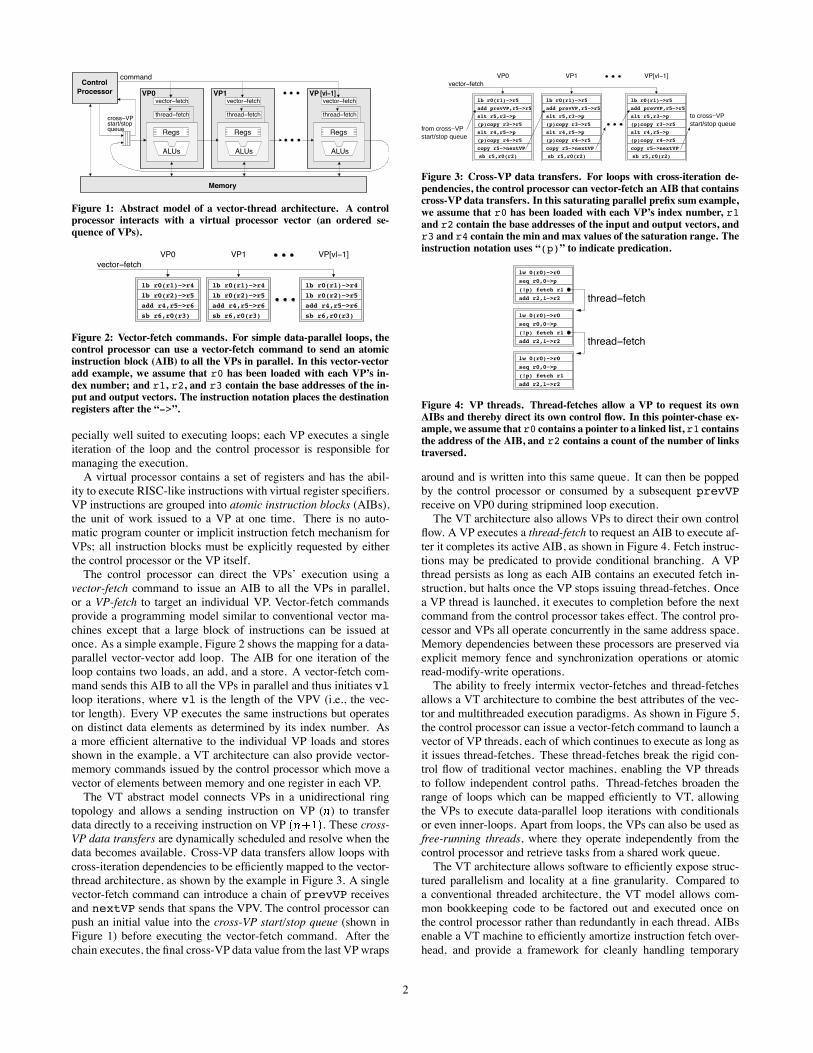
Figure 1: Abstract model of a vector-thread architecture. A controlprocessor interacts with a virtual processor vector (an ordered se-
quence of VPs).
vector!fetch
VP1 VP[vl!1]VP0
sb r6,r0(r3)
add r4,r5!>r6
lb r0(r2)!>r5
sb r6,r0(r3)
add r4,r5!>r6
lb r0(r2)!>r5
lb r0(r1)!>r4
sb r6,r0(r3)
add r4,r5!>r6
lb r0(r2)!>r5
lb r0(r1)!>r4lb r0(r1)!>r4
Figure 2: Vector-fetch commands. For simple data-parallel loops, thecontrol processor can use a vector-fetch command to send an atomic
instruction block (AIB) to all the VPs in parallel. In this vector-vector
add example, we assume that r0 has been loaded with each VP’s in-
dex number; and r1, r2, and r3 contain the base addresses of the in-put and output vectors. The instruction notation places the destination
registers after the “->”.
pecially well suited to executing loops; each VP executes a single
iteration of the loop and the control processor is responsible for
managing the execution.
A virtual processor contains a set of registers and has the abil-
ity to execute RISC-like instructions with virtual register specifiers.
VP instructions are grouped into atomic instruction blocks (AIBs),
the unit of work issued to a VP at one time. There is no auto-
matic program counter or implicit instruction fetch mechanism for
VPs; all instruction blocks must be explicitly requested by either
the control processor or the VP itself.
The control processor can direct the VPs’ execution using a
vector-fetch command to issue an AIB to all the VPs in parallel,
or a VP-fetch to target an individual VP. Vector-fetch commands
provide a programming model similar to conventional vector ma-
chines except that a large block of instructions can be issued at
once. As a simple example, Figure 2 shows the mapping for a data-
parallel vector-vector add loop. The AIB for one iteration of the
loop contains two loads, an add, and a store. A vector-fetch com-
mand sends this AIB to all the VPs in parallel and thus initiates vl
loop iterations, where vl is the length of the VPV (i.e., the vec-
tor length). Every VP executes the same instructions but operates
on distinct data elements as determined by its index number. As
a more efficient alternative to the individual VP loads and stores
shown in the example, a VT architecture can also provide vector-
memory commands issued by the control processor which move a
vector of elements between memory and one register in each VP.
The VT abstract model connects VPs in a unidirectional ring
topology and allows a sending instruction on VP ( ) to transfer
data directly to a receiving instruction on VP . These cross-
VP data transfers are dynamically scheduled and resolve when the
data becomes available. Cross-VP data transfers allow loops with
cross-iteration dependencies to be efficiently mapped to the vector-
thread architecture, as shown by the example in Figure 3. A single
vector-fetch command can introduce a chain of prevVP receives
and nextVP sends that spans the VPV. The control processor can
push an initial value into the cross-VP start/stop queue (shown in
Figure 1) before executing the vector-fetch command. After the
chain executes, the final cross-VP data value from the last VP wraps
vector!fetch
from cross−VPstart/stop queue
start/stop queueto cross−VP
VP0 VP1 VP[vl!1]
add prevVP,r5!>r5
lb r0(r1)!>r5
slt r5,r3!>p
(p)copy r3!>r5
slt r4,r5!>p
(p)copy r4!>r5
copy r5!>nextVP
sb r5,r0(r2)
add prevVP,r5!>r5
lb r0(r1)!>r5
slt r5,r3!>p
(p)copy r3!>r5
slt r4,r5!>p
(p)copy r4!>r5
copy r5!>nextVP
sb r5,r0(r2)
add prevVP,r5!>r5
lb r0(r1)!>r5
slt r5,r3!>p
(p)copy r3!>r5
slt r4,r5!>p
(p)copy r4!>r5
copy r5!>nextVP
sb r5,r0(r2)
Figure 3: Cross-VP data transfers. For loops with cross-iteration de-
pendencies, the control processor can vector-fetch an AIB that containscross-VP data transfers. In this saturating parallel prefix sum example,
we assume that r0 has been loaded with each VP’s index number, r1
and r2 contain the base addresses of the input and output vectors, andr3 and r4 contain the min and max values of the saturation range. The
instruction notation uses “(p)” to indicate predication.
thread!fetch
thread!fetchadd r2,1!>r2
seq r0,0!>p
lw 0(r0)!>r0
(!p) fetch r1
add r2,1!>r2
(!p) fetch r1
lw 0(r0)!>r0
seq r0,0!>p
add r2,1!>r2
(!p) fetch r1
seq r0,0!>p
lw 0(r0)!>r0
Figure 4: VP threads. Thread-fetches allow a VP to request its own
AIBs and thereby direct its own control flow. In this pointer-chase ex-ample, we assume that r0 contains a pointer to a linked list, r1 contains
the address of the AIB, and r2 contains a count of the number of links
traversed.
around and is written into this same queue. It can then be popped
by the control processor or consumed by a subsequent prevVP
receive on VP0 during stripmined loop execution.
The VT architecture also allows VPs to direct their own control
flow. A VP executes a thread-fetch to request an AIB to execute af-
ter it completes its active AIB, as shown in Figure 4. Fetch instruc-
tions may be predicated to provide conditional branching. A VP
thread persists as long as each AIB contains an executed fetch in-
struction, but halts once the VP stops issuing thread-fetches. Once
a VP thread is launched, it executes to completion before the next
command from the control processor takes effect. The control pro-
cessor and VPs all operate concurrently in the same address space.
Memory dependencies between these processors are preserved via
explicit memory fence and synchronization operations or atomic
read-modify-write operations.
The ability to freely intermix vector-fetches and thread-fetches
allows a VT architecture to combine the best attributes of the vec-
tor and multithreaded execution paradigms. As shown in Figure 5,
the control processor can issue a vector-fetch command to launch a
vector of VP threads, each of which continues to execute as long as
it issues thread-fetches. These thread-fetches break the rigid con-
trol flow of traditional vector machines, enabling the VP threads
to follow independent control paths. Thread-fetches broaden the
range of loops which can be mapped efficiently to VT, allowing
the VPs to execute data-parallel loop iterations with conditionals
or even inner-loops. Apart from loops, the VPs can also be used as
free-running threads, where they operate independently from the
control processor and retrieve tasks from a shared work queue.
The VT architecture allows software to efficiently expose struc-
tured parallelism and locality at a fine granularity. Compared to
a conventional threaded architecture, the VT model allows com-
mon bookkeeping code to be factored out and executed once on
the control processor rather than redundantly in each thread. AIBs
enable a VT machine to efficiently amortize instruction fetch over-
head, and provide a framework for cleanly handling temporary
2
VP0
VP4
VP8
VP12
ALUAIB
cache ALUAIB
cacheALUAIB
cache
VP1
VP5
VP9
VP13
VP2
VP6
VP10
VP14
ALUAIB
cache
VP3
VP7
VP11
VP15
command
cross!VPstart/stopqueue
AIB FillUnit
addr.
miss
Processor
Control
L1 Cache
cmd!Q
VP
directive
Command Management Unit
thread!fetch
Execution Cluster
execute
Lane 0
AIBtags
cmd!Q
VP
directive
Command Management Unit
thread!fetch
Execution Cluster
execute
Lane 3
AIBtags
cmd!Q
VP
directive
Command Management Unit
thread!fetch
Execution Cluster
execute
Lane 1
AIBtags
cmd!Q
VP
directive
Command Management Unit
thread!fetch
Execution Cluster
execute
Lane 2
AIBtags
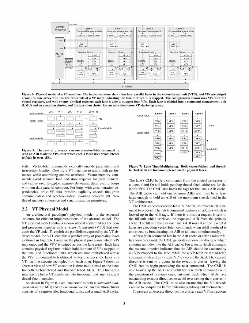
Figure 6: Physical model of a VT machine. The implementation shown has four parallel lanes in the vector-thread unit (VTU), and VPs are striped
across the lane array with the low-order bits of a VP index indicating the lane to which it is mapped. The configuration shown uses VPs with fivevirtual registers, and with twenty physical registers each lane is able to support four VPs. Each lane is divided into a command management unit
(CMU) and an execution cluster, and the execution cluster has an associated cross-VP start-stop queue.
vector!fetch
vector!fetch
vector!fetch
AIB
VP[vl!1]VP3VP2VP1VP0
thread!fetch
Figure 5: The control processor can use a vector-fetch command tosend an AIB to all the VPs, after which each VP can use thread-fetches
to fetch its own AIBs.
state. Vector-fetch commands explicitly encode parallelism and
instruction locality, allowing a VT machine to attain high perfor-
mance while amortizing control overhead. Vector-memory com-
mands avoid separate load and store requests for each element,
and can be used to exploit memory data-parallelism even in loops
with non-data-parallel compute. For loops with cross-iteration de-
pendencies, cross-VP data transfers explicitly encode fine-grain
communication and synchronization, avoiding heavyweight inter-
thread memory coherence and synchronization primitives.
2.2 VT Physical Model
An architectural paradigm’s physical model is the expected
structure for efficient implementations of the abstract model. The
VT physical model contains a conventional scalar unit for the con-
trol processor together with a vector-thread unit (VTU) that exe-
cutes the VP code. To exploit the parallelism exposed by the VT ab-
stract model, the VTU contains a parallel array of processing lanes
as shown in Figure 6. Lanes are the physical processors which VPs
map onto, and the VPV is striped across the lane array. Each lane
contains physical registers, which hold the state of VPs mapped to
the lane, and functional units, which are time-multiplexed across
the VPs. In contrast to traditional vector machines, the lanes in a
VT machine execute decoupled from each other. Figure 7 shows an
abstract view of how VP execution is time-multiplexed on the lanes
for both vector-fetched and thread-fetched AIBs. This fine-grain
interleaving helps VT machines hide functional unit, memory, and
thread-fetch latencies.
As shown in Figure 6, each lane contains both a command man-
agement unit (CMU) and an execution cluster. An execution cluster
consists of a register file, functional units, and a small AIB cache.
Time
thread!fetch
vector!fetch
vector!fetchLane 0 Lane 3Lane 1 Lane 2
VP0
VP4
VP8
VP0
VP4
VP8
VP0
VP7VP4
VP1
VP5
VP9
VP1
VP5
VP9
VP2
VP10
VP6
VP2
VP2
VP6
VP10
VP3
VP7
VP11
VP3
VP7
VP11
VP3
Figure 7: Lane Time-Multiplexing. Both vector-fetched and thread-fetched AIBs are time-multiplexed on the physical lanes.
The lane’s CMU buffers commands from the control processor in
a queue (cmd-Q) and holds pending thread-fetch addresses for the
lane’s VPs. The CMU also holds the tags for the lane’s AIB cache.
The AIB cache can hold one or more AIBs and must be at least
large enough to hold an AIB of the maximum size defined in the
VT architecture.
The CMU chooses a vector-fetch, VP-fetch, or thread-fetch com-
mand to process. The fetch command contains an address which is
looked up in the AIB tags. If there is a miss, a request is sent to
the fill unit which retrieves the requested AIB from the primary
cache. The fill unit handles one lane’s AIB miss at a time, except if
lanes are executing vector-fetch commands when refill overhead is
amortized by broadcasting the AIB to all lanes simultaneously.
After a fetch command hits in the AIB cache or after a miss refill
has been processed, the CMU generates an execute directive which
contains an index into the AIB cache. For a vector-fetch command
the execute directive indicates that the AIB should be executed by
all VPs mapped to the lane, while for a VP-fetch or thread-fetch
command it identifies a single VP to execute the AIB. The execute
directive is sent to a queue in the execution cluster, leaving the
CMU free to begin processing the next command. The CMU is
able to overlap the AIB cache refill for new fetch commands with
the execution of previous ones, but must track which AIBs have
outstanding execute directives to avoid overwriting their entries in
the AIB cache. The CMU must also ensure that the VP threads
execute to completion before initiating a subsequent vector-fetch.
To process an execute directive, the cluster reads VP instructions
3

one by one from the AIB cache and executes them for the appropri-
ate VP. When processing an execute-directive from a vector-fetch
command, all of the instructions in the AIB are executed for one VP
before moving on to the next. The virtual register indices in the VP
instructions are combined with the active VP number to create an
index into the physical register file. To execute a fetch instruction,
the cluster sends the requested AIB address to the CMU where the
VP’s associated pending thread-fetch register is updated.
The lanes in the VTU are inter-connected with a unidirectional
ring network to implement the cross-VP data transfers. When a
cluster encounters an instruction with a prevVP receive, it stalls
until the data is available from its predecessor lane. When the VT
architecture allows multiple cross-VP instructions in a single AIB,
with some sends preceding some receives, the hardware implemen-
tation must provide sufficient buffering of send data to allow all the
receives in an AIB to execute. By induction, deadlock is avoided if
each lane ensures that its predecessor can never be blocked trying
to send it cross-VP data.
3. The SCALE VT ArchitectureSCALE is an instance of the VT architectural paradigm designed
for embedded systems. The SCALE architecture has a MIPS-based
control processor extended with a VTU. The SCALE VTU aims to
provide high performance at low power for a wide range of appli-
cations while using only a small area. This section describes the
SCALE VT architecture, presents a simple code example imple-
mented on SCALE, and gives an overview of the SCALE microar-
chitecture and SCALE processor prototype.
3.1 SCALE Extensions to VT
Clusters
To improve performance while reducing area, energy and circuit
delay, SCALE extends the single-cluster VT model (shown in Fig-
ure 1) by partitioning VPs into multiple execution clusters with in-
dependent register sets. VP instructions target an individual cluster
and perform RISC-like operations. Source operands must be lo-
cal to the cluster, but results can be written to any cluster in the
VP, and an instruction can write its result to multiple destinations.
Each cluster within a VP has a separate predicate register, and in-
structions can be positively or negatively predicated.
SCALE clusters are heterogeneous, but all clusters support basic
integer operations. Cluster 0 additionally supports memory access
instructions, cluster 1 supports fetch instructions, and cluster 3 sup-
ports integer multiply and divide. Though not used in this paper, the
SCALE architecture allows clusters to be enhanced with layers of
additional functionality (e.g., floating-point operations, fixed-point
operations, and sub-word SIMD operations), or new clusters to be
added to perform specialized operations.
Registers and VP Configuration
The general registers in each cluster of a VP are categorized as ei-
ther private registers (pr’s) and shared registers (sr’s). Both pri-
vate and shared registers can be read and written by VP instructions
and by commands from the control processor. The main difference
is that private registers preserve their values between AIBs, while
shared registers may be overwritten by a different VP. Shared reg-
isters can be used as temporary state within an AIB to increase the
number of VPs that can be supported by a fixed number of physical
registers. The control processor can also vector-write the shared
registers to broadcast scalar values and constants used by all VPs.
In addition to the general registers, each cluster also has
programmer-visible chain registers (cr0 and cr1) associated with
the two ALU input operands. These can be used as sources and
destinations to avoid reading and writing the register files. Like
shared registers, chain registers may be overwritten between AIBs,
and they are also implicitly overwritten when a VP instruction uses
their associated operand position. Cluster 0 has a special chain reg-
ister called the store-data (sd) register through which all data for
VP stores must pass.
In the SCALE architecture, the control processor configures the
VPs by indicating how many shared and private registers are re-
quired in each cluster. The length of the virtual processor vector
changes with each re-configuration to reflect the maximum num-
ber of VPs that can be supported. This operation is typically done
once outside each loop, and state in the VPs is undefined across re-
configurations. Within a lane, the VTU maps shared VP registers
to shared physical registers. Control processor vector-writes to a
shared register are broadcast to each lane, but individual VP writes
to a shared register are not coherent across lanes, i.e., the shared
registers are not global registers.
Vector-Memory Commands
In addition to VP load and store instructions, SCALE defines
vector-memory commands issued by the control processor for effi-
cient structured memory accesses. Like vector-fetch commands,
these operate across the virtual processor vector; a vector-load
writes the load data to a private register in each VP, while a vector-
store reads the store data from a private register in each VP. SCALE
also supports vector-load commands which target shared registers
to retrieve values used by all VPs. In addition to the typical unit-
stride and strided vector-memory access patterns, SCALE provides
vector segment accesses where each VP loads or stores several con-
tiguous memory elements to support “array-of-structures” data lay-
outs efficiently.
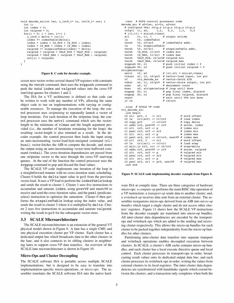
3.2 SCALE Code Example
This section presents a simple code example to show how
SCALE is programmed. The C code in Figure 8 implements a sim-
plified version of the ADPCM speech decoder. Input is read from
a unit-stride byte stream and output is written to a unit-stride half-
word stream. The loop is non-vectorizable because it contains two
loop-carried dependencies: the index and valpred variables are
accumulated from one iteration to the next with saturation. The
loop also contains two table lookups.
The SCALE code to implement the example decoder function
is shown in Figure 9. The code is divided into two sections with
MIPS control processor code in the .text section and SCALEVP
code in the .sisa (SCALE ISA) section. The SCALE VP code
implements one iteration of the loop with a single AIB; cluster 0
accesses memory, cluster 1 accumulates index, cluster 2 accumu-
lates valpred, and cluster 3 does the multiply.
The control processor first configures the VPs using the vcfgvl
command to indicate the register requirements for each cluster. In
this example, c0 uses one private register to hold the input data and
two shared registers to hold the table pointers; c1 and c2 each use
three shared registers to hold the min and max saturation values
and a temporary; c2 also uses a private register to hold the out-
put value; and c3 uses only chain registers so it does not need any
shared or private registers. The configuration indirectly sets vl-
max, the maximum vector length. In a SCALE implementation
with 32 physical registers per cluster and four lanes, vlmax would
be: , limited by the register demands of
cluster 2. The vcfgvl command also sets vl, the active vector-
length, to the minimum of vlmax and the length argument pro-
vided; the resulting length is returned as a result. The control pro-
4
void decode_ex(int len, u_int8_t* in, int16_t* out) {int i;int index = 0;int valpred = 0;for(i = 0; i < len; i++) {
u_int8_t delta = in[i];index += indexTable[delta];index = index < IX_MIN ? IX_MIN : index;index = IX_MAX < index ? IX_MAX : index;valpred += stepsizeTable[index] * delta;valpred = valpred < VALP_MIN ? VALP_MIN : valpred;valpred = VALP_MAX < valpred ? VALP_MAX : valpred;out[i] = valpred;
}}
Figure 8: C code for decoder example.
cessor next vector-writes several shared VP registers with constants
using the vwrsh command, then uses the xvppush command to
push the initial index and valpred values into the cross-VP
start/stop queues for clusters 1 and 2.
The ISA for a VT architecture is defined so that code can
be written to work with any number of VPs, allowing the same
object code to run on implementations with varying or config-
urable resources. To manage the execution of the loop, the con-
trol processor uses stripmining to repeatedly launch a vector of
loop iterations. For each iteration of the stripmine loop, the con-
trol processor uses the setvl command which sets the vector-
length to the minimum of vlmax and the length argument pro-
vided (i.e., the number of iterations remaining for the loop); the
resulting vector-length is also returned as a result. In the de-
coder example, the control processor then loads the input using
an auto-incrementing vector-load-byte-unsigned command (vl-
buai), vector-fetches the AIB to compute the decode, and stores
the output using an auto-incrementing vector-store-halfword com-
mand (vshai). The cross-iteration dependencies are passed from
one stripmine vector to the next through the cross-VP start/stop
queues. At the end of the function the control processor uses the
xvppop command to pop and discard the final values.
The SCALE VP code implements one iteration of the loop in
a straightforward manner with no cross-iteration static scheduling.
Cluster 0 holds the delta input value in pr0 from the previous
vector-load. It uses a VP load to perform the indexTable lookup
and sends the result to cluster 1. Cluster 1 uses five instructions to
accumulate and saturate index, using prevVP and nextVP to
receive and send the cross-iteration value, and the psel (predicate-
select) instruction to optimize the saturation. Cluster 0 then per-
forms the stepsizeTable lookup using the index value, and
sends the result to cluster 3 where it is multiplied by delta. Clus-
ter 2 uses five instructions to accumulate and saturate valpred,
writing the result to pr0 for the subsequent vector-store.
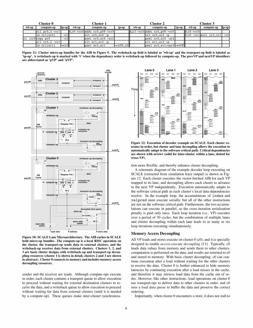
3.3 SCALEMicroarchitecture
The SCALE microarchitecture is an extension of the general VT
physical model shown in Figure 6. A lane has a single CMU and
one physical execution cluster per VP cluster. Each cluster has a
dedicated output bus which broadcasts data to the other clusters in
the lane, and it also connects to its sibling clusters in neighbor-
ing lanes to support cross-VP data transfers. An overview of the
SCALE lane microarchitecture is shown in Figure 10.
Micro-Ops and Cluster Decoupling
The SCALE software ISA is portable across multiple SCALE
implementations, but is designed to be easy to translate into
implementation-specific micro-operations, or micro-ops. The as-
sembler translates the SCALE software ISA into the native hard-
.text # MIPS control processor codedecode_ex: # a0=len, a1=in, a2=out
# configure VPs: c0:p,s c1:p,s c2:p,s c3:p,svcfgvl t1, a0, 1,2, 0,3, 1,3, 0,0# (vl,t1) = min(a0,vlmax)sll t1, t1, 1 # output stridela t0, indexTablevwrsh t0, c0/sr0 # indexTable addr.la t0, stepsizeTablevwrsh t0, c0/sr1 # stepsizeTable addr.vwrsh IX_MIN, c1/sr0 # index minvwrsh IX_MAX, c1/sr1 # index maxvwrsh VALP_MIN, c2/sr0# valpred minvwrsh VALP_MAX, c2/sr1# valpred maxxvppush $0, c1 # push initial index = 0xvppush $0, c2 # push initial valpred = 0
stripmineloop:setvl t2, a0 # (vl,t2) = min(a0,vlmax)vlbuai a1, t2, c0/pr0 # vector-load input, inc ptrvf vtu_decode_ex # vector-fetch AIBvshai a2, t1, c2/pr0 # vector-store output, inc ptrsubu a0, t2 # decrement countbnez a0, stripmineloop # loop until donexvppop $0, c1 # pop final index, discardxvppop $0, c2 # pop final valpred, discardvsync # wait until VPs are donejr ra # return
.sisa # SCALE VP codevtu_decode_ex:
.aib beginc0 sll pr0, 2 -> cr1 # word offsetc0 lw cr1(sr0) -> c1/cr0 # load indexc0 copy pr0 -> c3/cr0 # copy deltac1 addu cr0, prevVP -> cr0 # accum. indexc1 slt cr0, sr0 -> p # index minc1 psel cr0, sr0 -> sr2 # index minc1 slt sr1, sr2 -> p # index maxc1 psel sr2, sr1 -> c0/cr0, nextVP # index maxc0 sll cr0, 2 -> cr1 # word offsetc0 lw cr1(sr1) -> c3/cr1 # load stepc3 mult.lo cr0, cr1 -> c2/cr0 # step*deltac2 addu cr0, prevVP -> cr0 # accum. valpredc2 slt cr0, sr0 -> p # valpred minc2 psel cr0, sr0 -> sr2 # valpred minc2 slt sr1, sr2 -> p # valpred maxc2 psel sr2, sr1 -> pr0, nextVP # valpred max.aib end
Figure 9: SCALE code implementing decoder example from Figure 8.
ware ISA at compile time. There are three categories of hardware
micro-ops: a compute-op performs the main RISC-like operation of
a VP instruction; a transport-op sends data to another cluster; and,
a writeback-op receives data sent from an external cluster. The as-
sembler reorganizes micro-ops derived from an AIB into micro-op
bundles which target a single cluster and do not access other clus-
ters’ registers. Figure 11 shows how the SCALE VP instructions
from the decoder example are translated into micro-op bundles.
All inter-cluster data dependencies are encoded by the transport-
ops and writeback-ops which are added to the sending and receiv-
ing cluster respectively. This allows the micro-op bundles for each
cluster to be packed together independently from the micro-op bun-
dles for other clusters.
Partitioning inter-cluster data transfers into separate transport
and writeback operations enables decoupled execution between
clusters. In SCALE, a cluster’s AIB cache contains micro-op bun-
dles, and each cluster has a local execute directive queue and local
control. Each cluster processes its transport-ops in order, broad-
casting result values onto its dedicated output data bus; and each
cluster processes its writeback-ops in order, writing the values from
external clusters to its local registers. The inter-cluster data depen-
dencies are synchronized with handshake signals which extend be-
tween the clusters, and a transaction only completes when both the
5
Cluster 0 Cluster 1 Cluster 2 Cluster 3
wb-op compute-op tp-op wb-op compute-op tp-op wb-op compute-op tp-op wb-op compute-op tp-op
sll pr0,2 cr1 c0 cr0 addu cr0,pVP cr0 c3 cr0 addu cr0,pVP cr0 c0 cr0
lw cr1(sr0) c1 slt cr0,sr0 p slt cr0,sr0 p c0 cr1 mult cr0,cr1 c2
c1 cr0 copy pr0 c3 psel cr0,sr0 sr2 psel cr0,sr0 sr2
sll cr0,2 cr1 slt sr1,sr2 p slt sr1,sr2 p
lw cr1(sr1) c3 psel sr2,sr1 nVP,c0 psel sr2,sr1 pr0 nVP
Figure 11: Cluster micro-op bundles for the AIB in Figure 9. The writeback-op field is labeled as ’wb-op’ and the transport-op field is labeled as
’tp-op’. A writeback-op is marked with ’ ’ when the dependency order is writeback-op followed by compute-op. The prevVP and nextVP identifiersare abbreviated as ’pVP’ and ’nVP’.
VP
VP
Cluster 2
Cluster 3
Cluster 1
Cluster 0
decoupled store queue
writeback−op decoupling
transport−op decoupling
transport−op decoupling
writeback−op decoupling
executioncompute−op
executioncompute−op
writeback!op
compute!op
transport!op
writeback!op
compute!op
transport!op
AIBCache
AIB
Cache
prevVP
prevVP
executedirective
data(4x32b)
nextVP
nextVP
nextVP
nextVP
load!data address store!data
Register File
ALU
cr0 cr1
ALU
cr0 cr1
store!op
sd
Register File
prevVP
prevVP
load?src
load!dataqueue
store!addrqueue
src.cluster
srccluster
dest
dest
src cluster
destcluster
destcluster
AIBs
AIBs
compute
compute
writeback
transport
writeback
transport
Figure 10: SCALE LaneMicroarchitecture. The AIB caches in SCALE
hold micro-op bundles. The compute-op is a local RISC operation on
the cluster, the transport-op sends data to external clusters, and the
writeback-op receives data from external clusters. Clusters 1, 2, and3 are basic cluster designs with writeback-op and transport-op decou-
pling resources (cluster 1 is shown in detail, clusters 2 and 3 are shown
in abstract). Cluster 0 connects to memory and includes memory accessdecoupling resources.
sender and the receiver are ready. Although compute-ops execute
in order, each cluster contains a transport queue to allow execution
to proceed without waiting for external destination clusters to re-
ceive the data, and a writeback queue to allow execution to proceed
without waiting for data from external clusters (until it is needed
by a compute-op). These queues make inter-cluster synchroniza-
C0 C1 C2 C3
Lane 2C0 C1 C2 C3
Lane 3C0 C1 C2 C3
mul
slt
sltpsel
psel
addslt
sltpsel
lwsll
psel
slt
sltpsel
psel
add
mul
addslt
sltpsel
psel
lwsll slt
sltpsel
psel
add
mul
addslt
sltpsel
psel
lwsll slt
sltpsel
psel
add
mul
addslt
sltpsel
lwsll
slt
sltpsel
psel
add
lwsll
slt
sltpsel
psel
add
mul
addslt
sltpsel
psel
lwsll
slt
sltpsel
psel
add
mul
lwsll
lwsll
slllwcpy
slllwcpy
slllwcpy
slllwcpy
VP11
add
slllwcpy
slt
sltpsel
psel
add
slllwcpy
slllwcpy
slllwcpy
psel
mul
addslt
sltpsel
psel
addslt
sltpsel
pselmul
addslt
sltpsel
psel
lwsll
slllwcpy
VP8
VP12
VP4VP5
VP9
VP13
VP14
VP10
VP6
VP7
slt
sltpsel
psel
add
mul
addslt
sltpsel
psel
Lane 0C0 C1 C2 C3
VP4
VP4
VP8
VP8
VP8
VP12
VP5
VP5
VP5
VP9
VP9
VP9
VP13
VP10
VP10
VP10
VP6
VP6
VP6
VP2
VP3
VP3
VP7
VP7
VP7
VP11
VP11
Time
Lane 1
Figure 12: Execution of decoder example on SCALE. Each cluster ex-
ecutes in-order, but cluster and lane decoupling allows the execution to
automatically adapt to the software critical path. Critical dependenciesare shown with arrows (solid for inter-cluster within a lane, dotted for
cross-VP).
tion more flexible, and thereby enhance cluster decoupling.
A schematic diagram of the example decoder loop executing on
SCALE (extracted from simulation trace output) is shown in Fig-
ure 12. Each cluster executes the vector-fetched AIB for each VP
mapped to its lane, and decoupling allows each cluster to advance
to the next VP independently. Execution automatically adapts to
the software critical path as each cluster’s local data dependencies
resolve. In the example loop, the accumulations of index and
valpred must execute serially, but all of the other instructions
are not on the software critical path. Furthermore, the two accumu-
lations can execute in parallel, so the cross-iteration serialization
penalty is paid only once. Each loop iteration (i.e., VP) executes
over a period of 30 cycles, but the combination of multiple lanes
and cluster decoupling within each lane leads to as many as six
loop iterations executing simultaneously.
Memory Access Decoupling
All VP loads and stores execute on cluster 0 (c0), and it is specially
designed to enable access-execute decoupling [11]. Typically, c0
loads data values from memory and sends them to other clusters,
computation is performed on the data, and results are returned to c0
and stored to memory. With basic cluster decoupling, c0 can con-
tinue execution after a load without waiting for the other clusters
to receive the data. Cluster 0 is further enhanced to hide memory
latencies by continuing execution after a load misses in the cache,
and therefore it may retrieve load data from the cache out of or-
der. However, like other instructions, load operations on cluster 0
use transport-ops to deliver data to other clusters in order, and c0
uses a load data queue to buffer the data and preserve the correct
ordering.
Importantly, when cluster 0 encounters a store, it does not stall to
6

RF
ctrl
AL
Us
hftr
mu
x/
latc
hA
IB$
ctrl
AIB
tag
s
RF
ctrl
AL
Us
hftr
mu
x/
latc
hA
IB$
RF
ctrl
AL
Us
hftr
mu
x/
latc
hA
IB$
RF
ctrl
AL
Us
hftr
mu
x/
latc
hA
IB$
RF
ctrl
AL
Us
hftr
mu
x/
latc
hA
IB$
ctrl
AIB
tag
s
RF
ctrl
AL
Us
hftr
mu
x/
latc
hA
IB$
RF
ctrl
AL
Us
hftr
mu
x/
latc
hA
IB$
RF
ctrl
AL
Us
hftr
mu
x/
latc
hA
IB$
RF
ctrl
AL
Us
hftr
mu
x/
latc
hA
IB$
ctrl
AIB
tag
s
RF
ctrl
AL
Us
hftr
mu
x/
latc
hA
IB$
RF
ctrl
AL
Us
hftr
mu
x/
latc
hA
IB$
RF
ctrl
AL
Us
hftr
mu
x/
latc
hA
IB$
RF
ctrl
AL
Us
hftr
mu
x/
latc
hA
IB$
ctrl
AIB
tag
s
RF
ctrl
AL
Us
hftr
mu
x/
latc
hA
IB$
RF
ctrl
AL
Us
hftr
mu
x/
latc
hA
IB$
RF
ctrl
AL
Us
hftr
mu
x/
latc
hA
IB$
CacheTags
Memory
Cache ControlInterface /
CacheBank(8KB)
CacheBank(8KB)
CacheBank(8KB)
CacheBank(8KB)
Me
mo
ry U
nit
Ld
/St
RF
by
pA
LU
sh
ftr
MD
PC
CP
0
ctrl
Cro
ssb
ar
MultDiv
Lane
Cluster
Control Processor
2.5
mm
4mm
Figure 13: Preliminary floorplan estimate for SCALE prototype. The
prototype contains a scalar control processor, four 32-bit lanes with
four execution clusters each, and 32KB of cache in an estimated10mm in 0.18 m technology.
wait for the data to be ready. Instead it buffers the store operation,
including the store address, in the decoupled store queue until the
store data is available. When a SCALE VP instruction targets the
sd register, the resulting transport-op sends data to the store unit
rather than to c0; thus, the store unit acts as a primary destination
for inter-cluster transport operations and it handles the writeback-
ops for sd. Store decoupling allows a lane’s load stream to slip
ahead of its store stream, but loads for a given VP are not allowed
to bypass previous stores to the same address by the same VP.
Vector-Memory Accesses
Vector-memory commands are sent to the clusters as special exe-
cute directives which generate micro-ops instead of reading them
from the AIB cache. For a vector-load, writeback-ops on the desti-
nation cluster receive the load data; and for a vector-store, compute-
ops and transport-ops on the source cluster read and send the store
data. Chaining is provided to allow overlapped execution of vector-
fetched AIBs and vector-memory operations.
The vector-memory commands are also sent to the vector-
memory unit which performs the necessary cache accesses. The
vector-memory unit can only send one address to the cache each cy-
cle, but it takes advantage of the structured access patterns to load
or store multiple elements with each access. The vector-memory
unit communicates load and store data to and from cluster 0 in each
lane to reuse the buffering already provided for the decoupled VP
loads and stores.
3.4 Prototype
We are currently designing a prototype SCALE processor, and
an initial floorplan is shown in Figure 13. The prototype contains a
single-issue MIPS scalar control processor, four 32-bit lanes with
four execution clusters each, and a 32KB shared primary cache.
The VTU has 32 registers per cluster and supports up to 128 vir-
tual processors. The prototype’s unified L1 cache is 32-way set-
associative [15] and divided into four banks. The vector memory
unit can perform a single access per cycle, fetching up to 128 bits
from a single bank, or all lanes can perform VP accesses from dif-
ferent banks. The cache is non-blocking and connects to off-chip
DDR2 SDRAM.
The area estimate of around 10mm in 0.18 m technology is
based on microarchitecture-level datapath designs for the control
processor and VTU lanes; cell dimensions based on layout for the
datapath blocks, register files, CAMs, SRAM arrays, and cross-
bars; and estimates for the synthesized control logic and external
interface overhead. We have designed the SCALE prototype to
Vector-Thread Unit
Number of lanes 4
Clusters per lane 4
Registers per cluster 32
AIB cache uops per cluster 32
Intra-cluster bypass latency 0 cycles
Intra-lane transport latency 1 cycle
Cross-VP transport latency 0 cycles
Clock frequency 400MHz
L1 Unified Cache
Size 32KB
Associativity 32 (CAM tags)
Line size 32B
Banks 4
Maximum bank access width 16B
Store miss policy write-allocate/write-back
Load-use latency 2 cycles
Memory System
DRAM type DDR2
Data bus width 64 bits
DRAM clock frequency 200MHz
Data bus frequency 400MHz
Minimum load-use latency 35 processor cycles
Table 1: Default parameters for SCALE simulations.
fit into a compact area to reduce wire delays and design complex-
ity, and to support tiling of multiple SCALE processors on a CMP
for increased processing throughput. The clock frequency target is
400MHz based on a 25 FO4 cycle time, chosen as a compromise
between performance, power, and design complexity.
4. EvaluationThis section contains an evaluation and analysis of SCALE run-
ning a diverse selection of embedded benchmark codes. We first
describe the simulation methodology and benchmarks, then discuss
how the benchmark codes were mapped to the VT architecture and
the resulting efficiency of execution.
4.1 Programming and Simulation Methodology
SCALE was designed to be compiler-friendly, and a C compiler
is under development. For the results in this paper, all VTU code
was hand-written in SCALE assembler (as in Figure 9) and linked
with C code compiled for the MIPS control processor using gcc.
The same binary code was used across all SCALE configurations.
A detailed cycle-level, execution-driven microarchitectural sim-
ulator has been developed based on the prototype design. De-
tails modeled in the VTU simulation include cluster execution of
micro-ops governed by execute-directives; cluster decoupling and
dynamic inter-cluster data dependency resolution; memory access
decoupling; operation of the vector-memory unit; operation of
the command management unit, including vector-fetch and thread-
fetch commands with AIB tag-checking and miss handling; and the
AIB fill unit and its contention for the primary cache.
The VTU simulation is complemented by a cycle-based mem-
ory system simulation which models the multi-requester, multi-
banked, non-blocking, highly-associative CAM-based cache and
a detailed memory controller and DRAM model. The cache ac-
curately models bank conflicts between different requesters; ex-
erts back-pressure in response to cache contention; tracks pend-
ing misses and merges in new requests; and models cache-line re-
fills and writebacks. The DRAM simulation is based on the DDR2
chips used in the prototype design, and models a 64-bit wide mem-
ory port clocked at 200MHz (400Mb/s/pin) including page refresh,
precharge and burst effects.
The default simulation parameters are based on the prototype and
are summarized in Table 1. An intra-lane transport from one cluster
to another has a latency of one cycle (i.e. there will be a one cycle
7
bubble between the producing instruction and the dependent in-
struction). Cross-VP transports are able to have zero cycle latency
because the clusters are physically closer together and there is less
fan-in for the receive operation. Cache accesses have a two cy-
cle latency (two bubble cycles between load and use), and accesses
which miss in the cache have a minimum latency of 35 cycles.
To show scaling effects, we model four SCALE configurations
with one, two, four, and eight lanes. The one, two, and four
lane configurations each include four cache banks and one 64-bit
DRAM port. For eight lanes, the memory system was doubled to
eight cache banks and two 64-bit memory ports to appropriately
match the increased compute bandwidth.
4.2 Benchmarks and Results
We have implemented a selection of benchmarks (Table 2) to
illustrate the key features of SCALE, including examples from net-
work processing, image processing, cryptography, and audio pro-
cessing. The majority of these benchmarks come from the EEMBC
benchmark suite. The EEMBC benchmarks may either be run “out-
of-the-box” (OTB) as compiled unmodified C code, or they may be
optimized (OPT) using assembly coding and arbitrary hand-tuning.
This enables a direct comparison of SCALE running hand-written
assembly code to optimized results from industry processors. Al-
though OPT results match the typical way in which these pro-
cessors are used, one drawback of this form of evaluation is that
performance depends greatly on programmer effort, especially as
EEMBC permits algorithmic and data-structure changes to many
of the benchmark kernels, and optimizations used for the reported
results are often unpublished. Also, not all of the EEMBC results
are available for all processors, as results are often submitted for
only one of the domain-specific suites (e.g., telecom).
We made algorithmic changes to several of the EEMBC bench-
marks: rotate blocks the algorithm to enable rotating an 8-bit
block completely in registers, pktflow implements the packet de-
scriptor queue using an array instead of a linked list, fir optimizes
the default algorithm to avoid copying and exploit reuse, fbital
uses a binary search to optimize the bit allocation, conven uses
bit packed input data to enable multiple bit-level operations to be
performed in parallel, and fft uses a radix-2 hybrid Stockham al-
gorithm to eliminate bit-reversal and increase vector lengths.
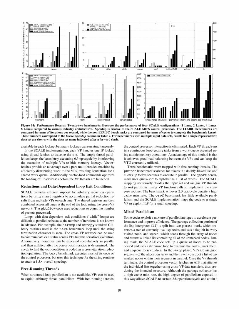
Figure 14 shows the simulated performance of the various
SCALE processor configurations relative to several reasonable
competitors from among those with the best published EEMBC
benchmark scores in each domain. For each of the different bench-
marks, Table 3 shows VP configuration and vector-length statistics,
and Tables 4 and 5 give statistics showing the effectiveness of the
SCALE control and data hierarchies. These are discussed further
in the following sections.
The AMD Au1100 was included to validate the SCALE con-
trol processor OTB performance, as it has a similar structure and
clock frequency, and also uses gcc. The Philips TriMedia TM
1300 is a five-issue VLIW processor with a 32-bit datapath. It runs
at 166MHz and has a 32KB L1 instruction cache and 16KB L1
data cache, with a 32-bit memory port running at 125MHz. The
Motorola PowerPC (MPC7447) is a four-issue out-of-order super-
scalar processor which runs at 1.3GHz and has 32 KB separate L1
instruction and data caches, a 512 KB L2 cache, and a 64-bit mem-
ory port running at 133MHz. The OPT results for the processor
use its Altivec SIMD unit which has a 128-bit datapath and four
execution units. The VIRAM processor [4] is a research vector
processor with four 64-bit lanes. VIRAM runs at 200MHz and in-
cludes 13MB of embedded DRAM supporting up to 256 bits each
of load and store data, and four independent addresses per cycle.
The BOPS Manta is a clustered VLIW DSP with four clusters each
capable of executing up to five instructions per cycle on 64-bit dat-
apaths. The Manta 2.0 runs at 136MHz with 128 KB of on-chip
memory connected to a 32-bit memory port running at 136MHz.
The TI TMS TMS320C6416 is a clustered VLIW DSP with two
clusters each capable of executing up to four instructions per cycle.
It runs at 720MHz and has a 16KB instruction cache and a 16KB
data cache together with 1MB of on-chip SRAM. The TI has a 64-
bit memory interface running at 720MHz. Apart from the Au1100
and SCALE, all other processors implement SIMD operations on
packed subword values and these are widely exploited throughout
the benchmark set.
Overall, the results show that SCALE can flexibly provide com-
petitive performance with larger and more complex processors on a
wide range of codes from different domains, and that performance
generally scales well when adding new lanes. The results also illus-
trate the large speedups possible when algorithms are extensively
tuned for a highly parallel processor versus compiled from stan-
dard reference code. SCALE results for fft and viterbi are
not as competitive with the DSPs. This is partly due to these be-
ing preliminary versions of the code with further scope for tuning
(e.g., moving the current radix-2 FFT to radix-4 and using outer-
loop vectorization for viterbi) and partly due to the DSPs hav-
ing special support for these operations (e.g., complex multiply on
BOPS). We expect SCALE performance to increase significantly
with the addition of subword operations and with improvements to
the microarchitecture driven by these early results.
4.3 Mapping Parallelism to SCALE
The SCALE VT architecture allows software to explicitly en-
code the parallelism and locality available in an application. This
section evaluates the architecture’s expressiveness in mapping dif-
ferent types of code.
Data-Parallel Loops with No Control Flow
Data-parallel loops with no internal control flow, i.e. simple vec-
torizable loops, may be ported to the VT architecture in a similar
manner as other vector architectures. Vector-fetch commands en-
code the cross-iteration parallelism between blocks of instructions,
while vector-memory commands encode data locality and enable
optimized memory access. The EEMBC image processing bench-
marks (rgbcmy, rgbyiq, hpg) are examples of streaming vec-
torizable code for which SCALE is able to achieve high perfor-
mance that scales with the number of lanes in the VTU. A 4-lane
SCALE achieves performance competitive with VIRAM for rg-
byiq and rgbcmy despite having half the main memory band-
width, primarily because VIRAM is limited by strided accesses
while SCALE refills the cache with unit-stride bursts and then has
higher strided bandwidth into the cache. For the unit-stride hpg
benchmark, performance follows memory bandwidth with the 8-
lane SCALE approximately matching VIRAM.
Data-Parallel Loops with Conditionals
Traditional vector machines handle conditional code with predica-
tion (masking), but the VT architecture adds the ability to condi-
tionally branch. Predication can be less overhead for small condi-
tionals, but branching results in less work when conditional blocks
are large. EEMBC dither is an example of a large conditional
block in a data parallel loop. This benchmark converts a grey-scale
image to black and white, and the dithering algorithm handles white
pixels as a special case. In the SCALE code, each VP executes a
conditional fetch for each pixel, executing only 18 SCALE instruc-
tions for white pixels versus 49 for non-white pixels.
8
EEMBC Data OTB OPT Kernel Ops/ Mem B/ Loop Type Mem
Benchmarks Set Itr/Sec Itr/Sec Speedup Cycle Cycle DP DC XI DI DE FT VM VP Description
rgbcmy consumer - 126 1505 11.9 6.1 3.2 RGB to CMYK color conversion
rgbyiq consumer - 56 1777 31.7 9.9 3.1 RGB to YIQ color conversion
hpg consumer - 108 3317 30.6 9.5 2.0 High pass grey-scale filter
text office - 299 435 1.5 0.3 0.0 Printer language parsing
dither office - 149 653 4.4 5.0 0.2 Floyd-Steinberg grey-scale dithering
rotate office - 704 10112 14.4 7.5 0.0 Binary image 90 degree rotation
lookup network - 1663 8850 5.3 6.3 0.0 IP route lookup using Patricia Trie
ospf network - 6346 7044 1.1 1.3 0.0 Dijkstra shortest path first
512KB 6694 127677 19.1 7.8 0.6
pktflow network 1MB 2330 25609 11.0 3.0 3.6 IP packet processing
2MB 1189 13473 11.3 3.1 3.7
pntrch auto - 8771 38744 4.4 2.3 0.0 Pointer chasing, searching linked list
fir auto - 56724 6105006 107.6 8.7 0.3 Finite impulse response filter
typ 860 20897 24.3 4.0 0.0
fbital telecom step 12523 281938 22.5 2.5 0.0 Bit allocation for DSL modems
pent 1304 60958 46.7 3.6 0.0
fft telecom all 6572 89713 13.6 6.1 0.0 256-pt fixed-point complex FFT
viterb telecom all 1541 7522 4.9 4.2 0.0 Soft decision Viterbi decoder
data1 279339 3131115 11.2 4.8 0.2
autocor telecom data2 1888 64148 34.0 11.2 0.0 Fixed-point autocorrelation
data3 1980 78751 39.8 13.0 0.0
data1 2899 2447980 844.3 9.8 0.0
conven telecom data2 3361 3085229 917.8 10.4 0.0 Convolutional encoder
data3 4259 3703703 869.4 9.5 0.1
Other Data OTB Total OPT Total Kernel Ops/ Mem B/ Loop Type Mem
Benchmarks Set Cycles Cycles Speedup Cycle Cycle DP DC XI DI DE FT VM VP Description
rijndael MiBench large 420.8M 219.0M 2.4 2.5 0.0 Advanced Encryption Standard
sha MiBench large 141.3M 64.8M 2.2 1.8 0.0 Secure hash algorithm
qsort MiBench small 35.0M 21.4M 3.5 2.3 2.7 Quick sort of strings
adpcm enc Mediabench - 7.7M 4.3M 1.8 2.3 0.0 Adaptive Differential PCM encode
adpcm dec Mediabench - 6.3M 1.0M 7.9 6.7 0.0 Adaptive Differential PCM decode
li SpecInt95 test 1,340.0M 1,151.7M 5.5 2.8 2.7 Lisp interpreter
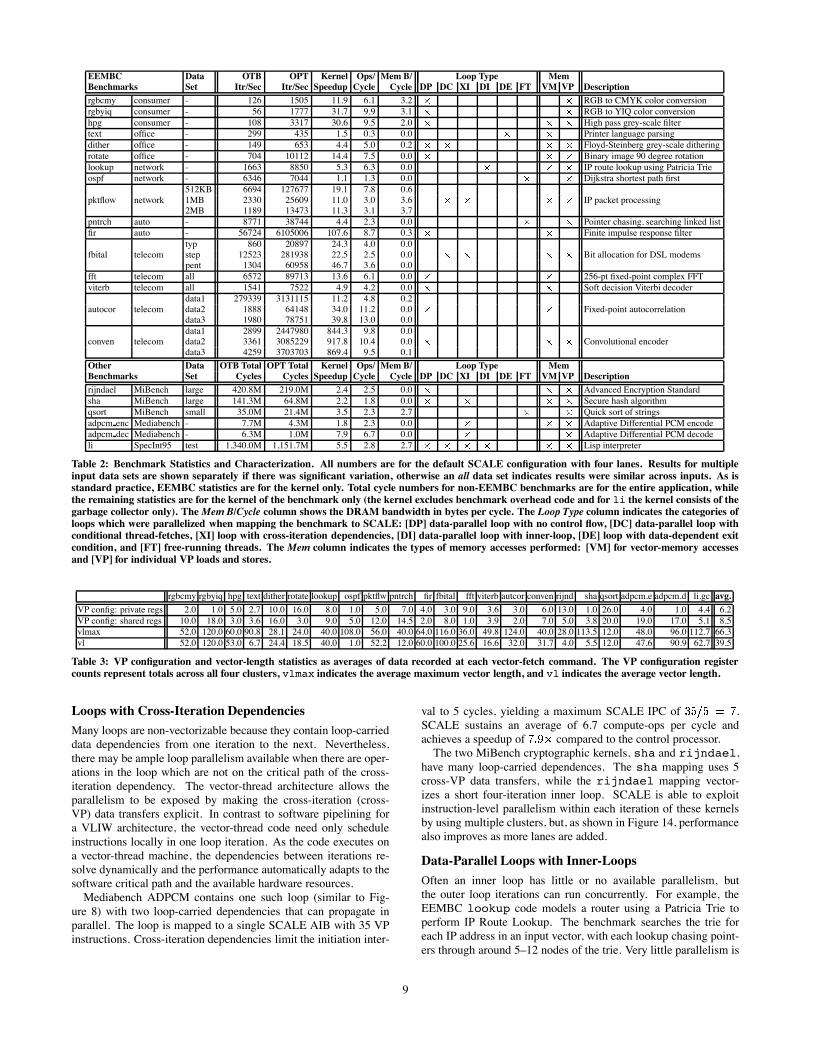
Table 2: Benchmark Statistics and Characterization. All numbers are for the default SCALE configuration with four lanes. Results for multiple
input data sets are shown separately if there was significant variation, otherwise an all data set indicates results were similar across inputs. As isstandard practice, EEMBC statistics are for the kernel only. Total cycle numbers for non-EEMBC benchmarks are for the entire application, while
the remaining statistics are for the kernel of the benchmark only (the kernel excludes benchmark overhead code and for li the kernel consists of the
garbage collector only). TheMem B/Cycle column shows the DRAM bandwidth in bytes per cycle. The Loop Type column indicates the categories ofloops which were parallelized when mapping the benchmark to SCALE: [DP] data-parallel loop with no control flow, [DC] data-parallel loop withconditional thread-fetches, [XI] loop with cross-iteration dependencies, [DI] data-parallel loop with inner-loop, [DE] loop with data-dependent exit
condition, and [FT] free-running threads. The Mem column indicates the types of memory accesses performed: [VM] for vector-memory accessesand [VP] for individual VP loads and stores.
rgbcmy rgbyiq hpg text dither rotate lookup ospf pktflw pntrch fir fbital fft viterb autcor conven rijnd sha qsort adpcm.e adpcm.d li.gc avg.
VP config: private regs 2.0 1.0 5.0 2.7 10.0 16.0 8.0 1.0 5.0 7.0 4.0 3.0 9.0 3.6 3.0 6.0 13.0 1.0 26.0 4.0 1.0 4.4 6.2
VP config: shared regs 10.0 18.0 3.0 3.6 16.0 3.0 9.0 5.0 12.0 14.5 2.0 8.0 1.0 3.9 2.0 7.0 5.0 3.8 20.0 19.0 17.0 5.1 8.5
vlmax 52.0 120.0 60.0 90.8 28.1 24.0 40.0 108.0 56.0 40.0 64.0 116.0 36.0 49.8 124.0 40.0 28.0 113.5 12.0 48.0 96.0 112.7 66.3
vl 52.0 120.0 53.0 6.7 24.4 18.5 40.0 1.0 52.2 12.0 60.0 100.0 25.6 16.6 32.0 31.7 4.0 5.5 12.0 47.6 90.9 62.7 39.5
Table 3: VP configuration and vector-length statistics as averages of data recorded at each vector-fetch command. The VP configuration register
counts represent totals across all four clusters, vlmax indicates the average maximum vector length, and vl indicates the average vector length.
Loops with Cross-Iteration Dependencies
Many loops are non-vectorizable because they contain loop-carried
data dependencies from one iteration to the next. Nevertheless,
there may be ample loop parallelism available when there are oper-
ations in the loop which are not on the critical path of the cross-
iteration dependency. The vector-thread architecture allows the
parallelism to be exposed by making the cross-iteration (cross-
VP) data transfers explicit. In contrast to software pipelining for
a VLIW architecture, the vector-thread code need only schedule
instructions locally in one loop iteration. As the code executes on
a vector-thread machine, the dependencies between iterations re-
solve dynamically and the performance automatically adapts to the
software critical path and the available hardware resources.
Mediabench ADPCM contains one such loop (similar to Fig-
ure 8) with two loop-carried dependencies that can propagate in
parallel. The loop is mapped to a single SCALE AIB with 35 VP
instructions. Cross-iteration dependencies limit the initiation inter-
val to 5 cycles, yielding a maximum SCALE IPC of .
SCALE sustains an average of 6.7 compute-ops per cycle and
achieves a speedup of compared to the control processor.
The two MiBench cryptographic kernels, sha and rijndael,
have many loop-carried dependences. The sha mapping uses 5
cross-VP data transfers, while the rijndael mapping vector-
izes a short four-iteration inner loop. SCALE is able to exploit
instruction-level parallelism within each iteration of these kernels
by using multiple clusters, but, as shown in Figure 14, performance
also improves as more lanes are added.
Data-Parallel Loops with Inner-Loops
Often an inner loop has little or no available parallelism, but
the outer loop iterations can run concurrently. For example, the
EEMBC lookup code models a router using a Patricia Trie to
perform IP Route Lookup. The benchmark searches the trie for
each IP address in an input vector, with each lookup chasing point-
ers through around 5–12 nodes of the trie. Very little parallelism is
9
rgbcmy rgbyiq hpg1
10
20
30
40
50
60
70S
peedup v
s. S
CA
LE
MIP
S C
ontr
ol P
rocessor
(OT
B)
text dither rotate lookup ospf pktflow/2MB pntrch
1
5
10
15
20
25
30
51x
fir1
40
80
120
160
200
fbital/pent fft viterb autocor/data31
10
20
30
40
50
60
70
80
90
100
110
120
Speedup v
s. S
CA
LE
MIP
S C
ontr
ol P
rocessor
(OT
B)
conven/data30
200
400
600
800
1000
1200
1400
1600
1800
2000
rijndael/large sha/large qsort/small adpcm_enc adpcm_dec li/test (GC)0
1
2
3
4
5
6
7
8
9
AMD Au1100 396 MHz (OTB)PowerPC 1.3 GHz (OTB)TM1300 166 MHz (OPT)VIRAM 200 MHz (OPT)SCALE 1/2/4/8 400 MHz (OPT)
AMD Au1100 396 MHz (OTB)PowerPC 1.3 GHz (OTB)PowerPC 1.3 GHz (OPT)SCALE 1/2/4/8 400 MHz (OPT)
SCALE 1/2/4/8 400 MHz (OPT)AMD Au1100 396 MHz (OTB)PowerPC 1.3 GHz (OTB)PowerPC 1.3 GHz (OPT)VIRAM 200 MHz (OPT)TI TMS320C6416 720 MHz (OPT)BOPS Manta v2.0 136 MHz (OPT)SCALE 1/2/4/8 400 MHz (OPT)
Figure 14: Performance Results: Twenty-two benchmarks illustrate the performance of four SCALE configurations (1 Lane, 2 Lanes, 4 Lanes,
8 Lanes) compared to various industry architectures. Speedup is relative to the SCALE MIPS control processor. The EEMBC benchmarks arecompared in terms of iterations per second, while the non-EEMBC benchmarks are compared in terms of cycles to complete the benchmark kernel.
These numbers correspond to the Kernel Speedup column in Table 2. For benchmarks with multiple input data sets, results for a single representativedata set are shown with the data set name indicated after a forward slash.
available in each lookup, but many lookups can run simultaneously.
In the SCALE implementation, each VP handles one IP lookup
using thread-fetches to traverse the trie. The ample thread paral-
lelism keeps the lanes busy executing 6.3 ops/cycle by interleaving
the execution of multiple VPs to hide memory latency. Vector-
fetches provide an advantage over a pure multithreaded machine by
efficiently distributing work to the VPs, avoiding contention for a
shared work queue. Additionally, vector-load commands optimize
the loading of IP addresses before the VP threads are launched.
Reductions and Data-Dependent Loop Exit Conditions
SCALE provides efficient support for arbitrary reduction opera-
tions by using shared registers to accumulate partial reduction re-
sults from multiple VPs on each lane. The shared registers are then
combined across all lanes at the end of the loop using the cross-VP
network. The pktflow code uses reductions to count the number
of packets processed.
Loops with data-dependent exit conditions (“while” loops) are
difficult to parallelize because the number of iterations is not known
in advance. For example, the strcmp and strcpy standard C li-
brary routines used in the text benchmark loop until the string
termination character is seen. The cross-VP network can be used
to communicate exit status across VPs but this serializes execution.
Alternatively, iterations can be executed speculatively in parallel
and then nullified after the correct exit iteration is determined. The
check to find the exit condition is coded as a cross-iteration reduc-
tion operation. The text benchmark executes most of its code on
the control processor, but uses this technique for the string routines
to attain a 1.5 overall speedup.
Free-Running Threads
When structured loop parallelism is not available, VPs can be used
to exploit arbitrary thread parallelism. With free-running threads,
the control processor interaction is eliminated. Each VP thread runs
in a continuous loop getting tasks from a work-queue accessed us-
ing atomic memory operations. An advantage of this method is that
it achieves good load-balancing between the VPs and can keep the
VTU constantly utilized.
Three benchmarks were mapped with free-running threads. The
pntrch benchmark searches for tokens in a doubly-linked list, and
allows up to five searches to execute in parallel. The qsort bench-
mark uses quick-sort to alphabetize a list of words. The SCALE
mapping recursively divides the input set and assigns VP threads
to sort partitions, using VP function calls to implement the com-
pare routine. The benchmark achieves 2.3 ops/cycle despite a high
cache miss rate. The ospf benchmark has little available paral-
lelism and the SCALE implementation maps the code to a single
VP to exploit ILP for a small speedup.
Mixed Parallelism
Some codes exploit a mixture of parallelism types to accelerate per-
formance and improve efficiency. The garbage collection portion of
the lisp interpreter (li) is split into two phases: mark, which tra-
verses a tree of currently live lisp nodes and sets a flag bit in every
visited node, and sweep, which scans through the array of nodes
and returns a linked list containing all of the unmarked nodes. Dur-
ing mark, the SCALE code sets up a queue of nodes to be pro-
cessed and uses a stripmine loop to examine the nodes, mark them,
and enqueue their children. In the sweep phase, VPs are assigned
segments of the allocation array and then each construct a list of un-
marked nodes within their segment in parallel. Once the VP threads
terminate, the control processor vector-fetches an AIB that stitches
the individual lists together using cross-VP data transfers, thus pro-
ducing the intended structure. Although the garbage collector has
a high cache miss rate, the high degree of parallelism exposed in
this way allows SCALE to sustain 2.8 operations/cycle and attain a
10
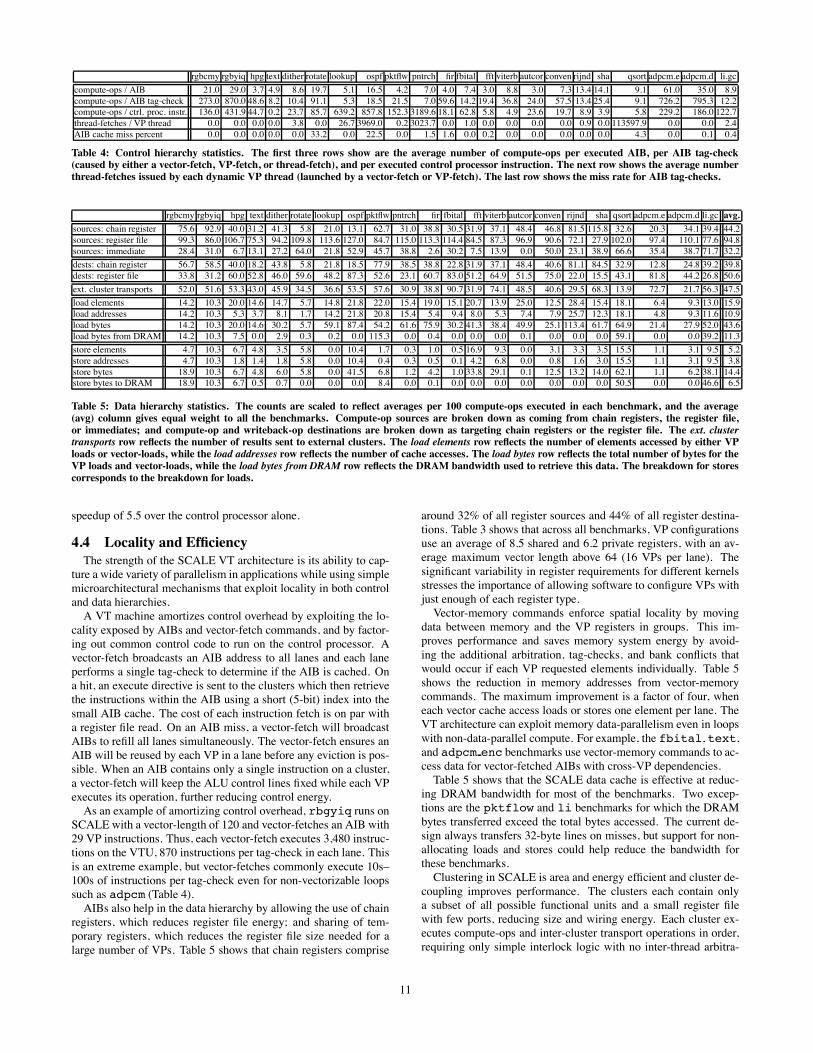
rgbcmy rgbyiq hpg text dither rotate lookup ospf pktflw pntrch fir fbital fft viterb autcor conven rijnd sha qsort adpcm.e adpcm.d li.gc
compute-ops / AIB 21.0 29.0 3.7 4.9 8.6 19.7 5.1 16.5 4.2 7.0 4.0 7.4 3.0 8.8 3.0 7.3 13.4 14.1 9.1 61.0 35.0 8.9
compute-ops / AIB tag-check 273.0 870.0 48.6 8.2 10.4 91.1 5.3 18.5 21.5 7.0 59.6 14.2 19.4 36.8 24.0 57.5 13.4 25.4 9.1 726.2 795.3 12.2
compute-ops / ctrl. proc. instr. 136.0 431.9 44.7 0.2 23.7 85.7 639.2 857.8 152.3 3189.6 18.1 62.8 5.8 4.9 23.6 19.7 8.9 3.9 5.8 229.2 186.0 122.7
thread-fetches / VP thread 0.0 0.0 0.0 0.0 3.8 0.0 26.7 3969.0 0.2 3023.7 0.0 1.0 0.0 0.0 0.0 0.0 0.9 0.0 113597.9 0.0 0.0 2.4
AIB cache miss percent 0.0 0.0 0.0 0.0 0.0 33.2 0.0 22.5 0.0 1.5 1.6 0.0 0.2 0.0 0.0 0.0 0.0 0.0 4.3 0.0 0.1 0.4
Table 4: Control hierarchy statistics. The first three rows show are the average number of compute-ops per executed AIB, per AIB tag-check(caused by either a vector-fetch, VP-fetch, or thread-fetch), and per executed control processor instruction. The next row shows the average number
thread-fetches issued by each dynamic VP thread (launched by a vector-fetch or VP-fetch). The last row shows the miss rate for AIB tag-checks.
rgbcmy rgbyiq hpg text dither rotate lookup ospf pktflw pntrch fir fbital fft viterb autcor conven rijnd sha qsort adpcm.e adpcm.d li.gc avg.
sources: chain register 75.6 92.9 40.0 31.2 41.3 5.8 21.0 13.1 62.7 31.0 38.8 30.5 31.9 37.1 48.4 46.8 81.5 115.8 32.6 20.3 34.1 39.4 44.2
sources: register file 99.3 86.0 106.7 75.3 94.2 109.8 113.6 127.0 84.7 115.0 113.3 114.4 84.5 87.3 96.9 90.6 72.1 27.9 102.0 97.4 110.1 77.6 94.8
sources: immediate 28.4 31.0 6.7 13.1 27.2 64.0 21.8 52.9 45.7 38.8 2.6 30.2 7.5 13.9 0.0 50.0 23.1 38.9 66.6 35.4 38.7 71.7 32.2
dests: chain register 56.7 58.5 40.0 18.2 43.8 5.8 21.8 18.5 77.9 38.5 38.8 22.8 31.9 37.1 48.4 40.6 81.1 84.5 32.9 12.8 24.8 39.2 39.8
dests: register file 33.8 31.2 60.0 52.8 46.0 59.6 48.2 87.3 52.6 23.1 60.7 83.0 51.2 64.9 51.5 75.0 22.0 15.5 43.1 81.8 44.2 26.8 50.6
ext. cluster transports 52.0 51.6 53.3 43.0 45.9 34.5 36.6 53.5 57.6 30.9 38.8 90.7 31.9 74.1 48.5 40.6 29.5 68.3 13.9 72.7 21.7 56.3 47.5
load elements 14.2 10.3 20.0 14.6 14.7 5.7 14.8 21.8 22.0 15.4 19.0 15.1 20.7 13.9 25.0 12.5 28.4 15.4 18.1 6.4 9.3 13.0 15.9
load addresses 14.2 10.3 5.3 3.7 8.1 1.7 14.2 21.8 20.8 15.4 5.4 9.4 8.0 5.3 7.4 7.9 25.7 12.3 18.1 4.8 9.3 11.6 10.9
load bytes 14.2 10.3 20.0 14.6 30.2 5.7 59.1 87.4 54.2 61.6 75.9 30.2 41.3 38.4 49.9 25.1 113.4 61.7 64.9 21.4 27.9 52.0 43.6
load bytes from DRAM 14.2 10.3 7.5 0.0 2.9 0.3 0.2 0.0 115.3 0.0 0.4 0.0 0.0 0.0 0.1 0.0 0.0 0.0 59.1 0.0 0.0 39.2 11.3
store elements 4.7 10.3 6.7 4.8 3.5 5.8 0.0 10.4 1.7 0.3 1.0 0.5 16.9 9.3 0.0 3.1 3.3 3.5 15.5 1.1 3.1 9.5 5.2
store addresses 4.7 10.3 1.8 1.4 1.8 5.8 0.0 10.4 0.4 0.3 0.5 0.1 4.2 6.8 0.0 0.8 1.6 3.0 15.5 1.1 3.1 9.5 3.8
store bytes 18.9 10.3 6.7 4.8 6.0 5.8 0.0 41.5 6.8 1.2 4.2 1.0 33.8 29.1 0.1 12.5 13.2 14.0 62.1 1.1 6.2 38.1 14.4
store bytes to DRAM 18.9 10.3 6.7 0.5 0.7 0.0 0.0 0.0 8.4 0.0 0.1 0.0 0.0 0.0 0.0 0.0 0.0 0.0 50.5 0.0 0.0 46.6 6.5
Table 5: Data hierarchy statistics. The counts are scaled to reflect averages per 100 compute-ops executed in each benchmark, and the average
(avg) column gives equal weight to all the benchmarks. Compute-op sources are broken down as coming from chain registers, the register file,
or immediates; and compute-op and writeback-op destinations are broken down as targeting chain registers or the register file. The ext. clustertransports row reflects the number of results sent to external clusters. The load elements row reflects the number of elements accessed by either VPloads or vector-loads, while the load addresses row reflects the number of cache accesses. The load bytes row reflects the total number of bytes for theVP loads and vector-loads, while the load bytes from DRAM row reflects the DRAM bandwidth used to retrieve this data. The breakdown for stores
corresponds to the breakdown for loads.
speedup of 5.5 over the control processor alone.
4.4 Locality and Efficiency
The strength of the SCALE VT architecture is its ability to cap-
ture a wide variety of parallelism in applications while using simple
microarchitectural mechanisms that exploit locality in both control
and data hierarchies.
A VT machine amortizes control overhead by exploiting the lo-
cality exposed by AIBs and vector-fetch commands, and by factor-
ing out common control code to run on the control processor. A
vector-fetch broadcasts an AIB address to all lanes and each lane
performs a single tag-check to determine if the AIB is cached. On
a hit, an execute directive is sent to the clusters which then retrieve
the instructions within the AIB using a short (5-bit) index into the
small AIB cache. The cost of each instruction fetch is on par with
a register file read. On an AIB miss, a vector-fetch will broadcast
AIBs to refill all lanes simultaneously. The vector-fetch ensures an
AIB will be reused by each VP in a lane before any eviction is pos-
sible. When an AIB contains only a single instruction on a cluster,
a vector-fetch will keep the ALU control lines fixed while each VP
executes its operation, further reducing control energy.
As an example of amortizing control overhead, rbgyiq runs on
SCALE with a vector-length of 120 and vector-fetches an AIB with
29 VP instructions. Thus, each vector-fetch executes 3,480 instruc-
tions on the VTU, 870 instructions per tag-check in each lane. This
is an extreme example, but vector-fetches commonly execute 10s–
100s of instructions per tag-check even for non-vectorizable loops
such as adpcm (Table 4).
AIBs also help in the data hierarchy by allowing the use of chain
registers, which reduces register file energy; and sharing of tem-
porary registers, which reduces the register file size needed for a
large number of VPs. Table 5 shows that chain registers comprise
around 32% of all register sources and 44% of all register destina-
tions. Table 3 shows that across all benchmarks, VP configurations
use an average of 8.5 shared and 6.2 private registers, with an av-
erage maximum vector length above 64 (16 VPs per lane). The
significant variability in register requirements for different kernels
stresses the importance of allowing software to configure VPs with
just enough of each register type.
Vector-memory commands enforce spatial locality by moving
data between memory and the VP registers in groups. This im-
proves performance and saves memory system energy by avoid-
ing the additional arbitration, tag-checks, and bank conflicts that
would occur if each VP requested elements individually. Table 5
shows the reduction in memory addresses from vector-memory
commands. The maximum improvement is a factor of four, when
each vector cache access loads or stores one element per lane. The
VT architecture can exploit memory data-parallelism even in loops
with non-data-parallel compute. For example, the fbital, text,
and adpcm enc benchmarks use vector-memory commands to ac-
cess data for vector-fetched AIBs with cross-VP dependencies.
Table 5 shows that the SCALE data cache is effective at reduc-
ing DRAM bandwidth for most of the benchmarks. Two excep-
tions are the pktflow and li benchmarks for which the DRAM
bytes transferred exceed the total bytes accessed. The current de-
sign always transfers 32-byte lines on misses, but support for non-
allocating loads and stores could help reduce the bandwidth for
these benchmarks.
Clustering in SCALE is area and energy efficient and cluster de-
coupling improves performance. The clusters each contain only
a subset of all possible functional units and a small register file
with few ports, reducing size and wiring energy. Each cluster ex-
ecutes compute-ops and inter-cluster transport operations in order,
requiring only simple interlock logic with no inter-thread arbitra-
11
tion or dynamic inter-cluster bypass detection. Independent control
on each cluster enables decoupled cluster execution to hide large
inter-cluster or memory latencies. This provides a very cheap form
of SMT where each cluster can be executing code for different VPs
on the same cycle (Figure 12).
5. Related WorkThe VT architecture draws from earlier vector architectures [9],
and like vector microprocessors [14, 6, 3] the SCALE VT imple-
mentation provides high throughput at low complexity. Similar to
CODE [5], SCALE uses decoupled clusters to simplify chaining
control and to reduce the cost of a large vector register file support-
ing many functional units. However, whereas CODE uses register
renaming to hide clusters from software, SCALE reduces hardware
complexity by exposing clustering and statically partitioning inter-
cluster transport and writeback operations.
The Imagine [8] stream processor is similar to vector machines,
with the main enhancement being the addition of stream load and
store instructions that pack and unpack arrays of multi-field records
stored in DRAM into multiple vector registers, one per field. In
comparison, SCALE uses a conventional cache to enable unit-
stride transfers from DRAM, and provides segment vector-memory
commands to transfer arrays of multi-field records between the
cache and VP registers. Like SCALE, Imagine improves register
file locality compared with traditional vector machines by execut-
ing all operations for one loop iteration before moving to the next.
However, Imagine instructions use a low-level VLIW ISA that ex-
poses machine details such as number of physical registers and
lanes, whereas SCALE provides a higher-level abstraction based
on VPs and AIBs.
VT enhances the traditional vector model to support loops with
cross-iteration dependencies and arbitrary internal control flow.
Chiueh’s multi-threaded vectorization [1] extends a vector ma-
chine to handle loop-carried dependencies, but is limited to a sin-
gle lane and requires the compiler to have detailed knowledge of
all functional unit latencies. Jesshope’s micro-threading [2] uses
a vector-fetch to launch micro-threads which each execute one
loop iteration, but whose execution is dynamically scheduled on
a per-instruction basis. In contrast to VT’s low-overhead direct
cross-VP data transfers, cross-iteration synchronization is done us-
ing full/empty bits on shared global registers. Like VT, Multi-
scalar [12] statically determines loop-carried register dependencies
and uses a ring to pass cross-iteration values. But Multiscalar uses
speculative execution with dynamic checks for memory dependen-
cies, while VT dispatches multiple non-speculative iterations si-
multaneously. Multiscalar can execute a wider range of loops in
parallel, but VT can execute many common parallel loop types with
much simpler logic and while using vector-memory operations.
Several other projects are developing processors capable of ex-
ploiting multiple forms of application parallelism. The Raw [13]
project connects a tiled array of simple processors. In contrast to
SCALE’s direct inter-cluster data transfers and cluster decoupling,
inter-tile communication on Raw is controlled by programmed
switch processors and must be statically scheduled to tolerate laten-
cies. The Smart Memories [7] project has developed an architecture
with configurable processing tiles which support different types of
parallelism, but it has different instruction sets for each type and
requires a reconfiguration step to switch modes. The TRIPS pro-
cessor [10] similarly must explicitly morph between instruction,
thread, and data parallelism modes. These mode switches limit the
ability to exploit multiple forms of parallelism at a fine-grain, in
contrast to SCALEwhich seamlessly combines vector and threaded
execution while also exploiting local instruction-level parallelism.
6. ConclusionThe vector-thread architectural paradigm allows software to
more efficiently encode the parallelism and locality present in many
applications, while the structure provided in the hardware-software
interface enables high-performance implementations that are effi-
cient in area and power. The VT architecture unifies support for all
types of parallelism and this flexibility enables new ways of paral-
lelizing codes, for example, by allowing vector-memory operations
to feed directly into threaded code. The SCALE prototype demon-
strates that the VT paradigm is well-suited to embedded applica-
tions, allowing a single relatively small design to provide competi-
tive performance across a range of application domains. Although
this paper has focused on applying VT to the embedded domain,
we anticipate that the vector-thread model will be widely applicable
in other domains including scientific computing, high-performance
graphics processing, and machine learning.
7. AcknowledgmentsThis work was funded in part by DARPA PAC/C award F30602-
00-2-0562, NSF CAREER award CCR-0093354, an NSF graduate
fellowship, donations from Infineon Corporation, and an equipment
donation from Intel Corporation.
8. References[1] T.-C. Chiueh. Multi-threaded vectorization. In ISCA-18, May 1991.
[2] C. R. Jesshope. Implementing an efficient vector instruction set in achip multi-processor using micro-threaded pipelines. AustraliaComputer Science Communications, 23(4):80–88, 2001.
[3] K. Kitagawa, S. Tagaya, Y. Hagihara, and Y. Kanoh. A hardwareoverview of SX-6 and SX-7 supercomputer. NEC Research &Development Journal, 44(1):2–7, Jan 2003.
[4] C. Kozyrakis. Scalable vector media-processors for embeddedsystems. PhD thesis, University of California at Berkeley, May 2002.
[5] C. Kozyrakis and D. Patterson. Overcoming the limitations ofconventional vector processors. In ISCA-30, June 2003.
[6] C. Kozyrakis, S. Perissakis, D. Patterson, T. Anderson, K. Asanovic,N. Cardwell, R. Fromm, J. Golbus, B. Gribstad, K. Keeton,R. Thomas, N. Treuhaft, and K. Yelick. Scalable Processors in theBillion-Transistor Era: IRAM. IEEE Computer, 30(9):75–78, Sept1997.
[7] K. Mai, T. Paaske, N. Jayasena, R. Ho, W. Dally, and M. Horowitz.Smart Memories: A modular reconfigurable architecture. In Proc.ISCA 27, pages 161–171, June 2000.
[8] S. Rixner, W. Dally, U. Kapasi, B. Khailany, A. Lopez-Lagunas,P. Mattson, and J. Owens. A bandwidth-efficient architecture formedia processing. In MICRO-31, Nov 1998.
[9] R. M. Russel. The CRAY-1 computer system. Communications of theACM, 21(1):63–72, Jan 1978.
[10] K. Sankaralingam, R. Nagarajan, H. Liu, C. Kim, J. Huh, D. Burger,S. W. Keckler, and C. Moore. Exploiting ILP, TLP, and DLP with thepolymorphous TRIPS architecture. In ISCA-30, June 2003.
[11] J. E. Smith. Dynamic instruction scheduling and the AstronauticsZS-1. IEEE Computer, 22(7):21–35, July 1989.
[12] G. S. Sohi, S. E. Breach, and T. N. Vijaykumar. Multiscalarprocessors. In ISCA-22, pages 414–425, June 1995.
[13] E. Waingold, M. Taylor, D. Srikrishna, V. Sarkar, W. Lee, V. Lee,J. Kim, M. Frank, P. Finch, R. Barua, J. Babb, S. Amarasinghe, andA. Agarwal. Baring it all to software: Raw machines. IEEEComputer, 30(9):86–93, Sept 1997.
[14] J. Wawrzynek, K. Asanovic, B. Kingsbury, J. Beck, D. Johnson, andN. Morgan. Spert-II: A vector microprocessor system. IEEEComputer, 29(3):79–86, Mar 1996.
[15] M. Zhang and K. Asanovic. Highly-associative caches for low-powerprocessors. In Kool Chips Workshop, MICRO-33, Dec 2000.
12