t a b l e o f c o n t e n t s - as cable-supported and cable-suspended roofs, offshore drilling ......
28
Transcript of t a b l e o f c o n t e n t s - as cable-supported and cable-suspended roofs, offshore drilling ......


Used as key components in such diverse
structures as cable-supported and cable-
suspended roofs, offshore drilling
equipment, and soaring suspension
bridges, Bethlehem Wire Rope products
are recognized the world over for superior
quality. Manufactured by Wirerope Works,
Inc., (WW), our wire, wire rope and
structural strand are fabricated to
meet the highest standards in the
industry. After all, we’re now in
our second century of excellence
at our comprehensive facility in
Williamsport, Pennsylvania. And
even though our name has undergone
several changes since 1886, our mission
remains the same: to manufacture
Bethlehem Wire Rope products of
the utmost quality, using the latest
technology backed by solid experience and
far-ranging expertise. All vital reasons
why choosing Bethlehem Wire Rope
products manufactured by WW will prove
to be an invaluable asset to your next
project—on land or sea.
2

3
t a b l e o f c o n t e n t s
Applications ................................................ page 4
Television and Radio Towers .................... page 4
Bridges ................................................. page 5-6
Cable Roof Structures .............................. page 7-8
Computer-Assisted Design and Detailing ......... page 9
Bethlehem Structural Strand ......................... page 10
Bethlehem Structural Wire Rope ..................... page 11
High Strength Structural Strand ..................... page 12
Custom Finishes ........................................... page 12
Prestretching ............................................... page 13-14
Striping ...................................................... page 14
Measuring ................................................... page 14
Corrosion Protection ..................................... page 14-15
End Terminations ......................................... page 16
Attaching Sockets ........................................ page 16
Proofloading ................................................ page 16
Certification ................................................ page 17
Order Specifications ...................................... page 17
End Termination Data Tables .......................... page 18-26
Wire rope and strand products will break if abused, misused or overused. Regular inspection and maintenance are necessary. Consult Industry recommendations and OSHA Standards before using.
Wirerope Works, Inc. expressly prohibits the resale of worn, previously owned and used Bethlehem Wire Rope and Strand products. Immediately following removal from service, all wire rope products
are to be properly disposed of in accordance with applicable municipal, state, and federal guidelines. Manufacturer shall not be liable for consequential or incidental damages or secondary charges
including but not limited to personal injury, labor costs, and a loss of profits resulting from the use of worn, previously owned and used products.
Wirerope Works, Inc. © 2007

television and radio towers
Early tower installations for radio broadcasting offered problems similar to those met in guying stacks, poles, derricks and similar structures. Guys for these moderate-height structures were commonly made of regular wire rope. The advent of television and FM broadcasting, however, created a need for towers of greater height. In fact, the idea of a tower being 2,000 feet tall or more is no longer uncommon. The guying of these larger towers presented problems not faced with the smaller towers. For example, wind and ice loads must now be considered, both during installation and in tensioning after erection. Structural strand is now used for guy systems. Where larger diameter wire rope was once used, structural strand, with its higher modulus of elasticity and lower diameter-to-strength ratio, allows for smaller diameter guys. This reduction in diameter reduces ice and wind loads, which may be important in the overall design of the tower. Structural strand’s higher modulus of elasticity (less stretch) also allows for less take-up of the bolts during tensioning. Uniformity in tensioning and deflection is necessary for tower guys.
Therefore, it is important that the structural strand guys have minimal constructional stretch, a high modulus of elasticity and accurate length measurements. Prestretching the strand eliminates most of the constructional stretch and contributes to the strand’s high modulus of elasticity. Proofloading may be used to prove the security of end attachments. Proofloading is done on WW’s 500-ton and 100-ton proofloading machines. Prestretching is done on WW’s 1600-foot tensioning track under closely controlled conditions. WW uses highly accurate, proprietary length measuring methods. Field tensioning of the guys is facilitated by our ability to supply precisely measured and completely documented strand assemblies. Bethlehem Structural Strand for tower guys is available in three different galvanized coating weights to meet a wide range of corrosion-resistant requirements. For additional information, refer to Corrosion Protection on pages 14 and 15. In addition to tower guys, WW also manufactures galvanized elevator hoist ropes for towers.
applications In addition to the applications listed above, Bethlehem Structural Strand is used for boom pendants on excavating equipment. For further information on Bethlehem Mining Rope and Strand products, please refer to our Bethlehem Mining Products catalog.
4

bridgessuspension bridges Suspension systems are ideal where long spans are required, as in highway and pedestrian bridges, supporting conveyors, pipe lines and overhead passageways in industrial plants, and overhead crossovers above railroads. When appearance, durability, utility and ease of construction are considered, suspension bridges are often the most economical to build. For example, flood damage to exposed piers is eliminated and difficult or dangerous pier foundations can be avoided with a suspension-cable construction. Often the entire problem area is spanned; the foundations can be located at economical installation points where they are least likely to be damaged. Great clearance is obtained since the supporting structure is above the floor and has no intermediate supports. Stiffening trusses may be incorporated into the design of foot bridges and similar bridges, where they may also serve as hand railings. These trusses add relatively little to the cost of the structure, and they ensure a bridge free from disturbing floor movement.
5

Bethlehem Structural Strand and Wire Rope is used for the main cables, suspenders and wind cables of highway, pedestrian and pipeline suspension bridges. WW manufactures Bethlehem Structural Strand through 51/2” diameter and Bethlehem Struc-tural Wire Rope up to 7” diameter. Prestretching greatly reduces the constructional stretch of the structural strand or wire rope and improves the overall elastic stability. While in the prestretcher, overall lengths and inter-mediate tower and suspender points can be measured to close tolerances under prescribed tensions.
tied arch bridges In a tied arch bridge, the bridge deck is suspended by struc-tural strand or wire rope hangers hung from a steel or concrete arch. Tied arch bridges normally cross short to medium spans. Bethlehem Structural Strand has been used in tied arch bridges having span lengths of more than 1,000 feet.
6
cable stayed bridges The cable stayed bridge is a relatively new type of bridge, in which structural cables radiate diagonally from one or more towers or pylons to a connection point on the bridge girder. This bridge form allows a very efficient use of material, which results in a lighter structure and less massive foundation. Cable stayed bridges have been built with a main span as long as 2,300 feet be-tween the towers. Frequently, the limiting constraint on span lengths is the permis-sible height of the pylon. Galvanized helical structural strand has been specified for cable stays as have several other cable configurations. Various types of socket attachment and corrosion protection systems have been used with varying degrees of success. WW recom-mends zinc-poured attachment of sockets. Corrosion protection systems are too varied and rapidly evolving to recommend a particular system. For further information, please consult WW’s Engineering Depart-ment.
vertical lift bridges In a vertical lift bridge, the movable span is balanced by counterweights located in the towers at each end of the span. Each corner of the span is connected to the counterweights by sets of large wire ropes which operate over parallel-grooved sheaves at the top of the towers. Using powered winch drums, smaller wire ropes raise and lower the movable span. The lengths of the counterweight ropes in each of the four corners must be closely matched to ensure equalization of tension. Uniform stretch is also an important factor. In vertical lift bridges where counterweight clearances are limited, ropes should have minimal constructional stretch. Counter-weight ropes can be prestretched to reduce constructional stretch, and measured under tension to ensure closer control of rope lengths. Normally, operating ropes do not require prestretching since minor length adjustments can be made at the drums.

cable roof structures In recent years, design and construction of structures with cable-supported and cable-suspended roofs has increased. As opposed to other methods, cable roof structures permit economical, column-free construction over large spans. Cable roofs also decrease the stresses on the superstructure, supporting members and the foundation, thereby permitting the use of fewer and lighter materials. Cable roofs offer a bold challenge to architects and structural engineers who seek new ways to utilize interesting techniques and materials. A loose description of a cable roof structure is any roof structure which uses steel cables as load-bearing, structural elements. Most roofs fall into one of two categories: (1) cable-suspended, or (2) cable-supported. A cable-suspended roof uses cables to directly carry the roof load. There are two variations of this principle: (1) cases where the roof deck is carried directly on the cable, and (2) cases where additional loads, such as ceiling frames, are suspended directly from and below the cable. In a cable-supported system, the roof loads are generally carried by rigid structural members. In this case, the cables serve as added support. The architectural forms of suspension roofs are numerous. If adequately treated in the conceptual design stage, structural suspension systems offer numerous architectural forms, not only for roofs, but for the entire building. The following are the most common types of sus-pension roofs.
catenaries
The most elementary structural suspension system is a catenary, which is similar to that of a suspension bridge. This system usually requires end towers and abutments to resist the tension in the catenary and a stiffening structure to eliminate the flutter in the roof system.
tents This system consists of parallel as-semblies or radial assemblies extending from one support point to various abut-ments, with the roofing material spanning between the assemblies. This system, in addition to its requirement of vertical posts within the covered space, makes no effort to solve the flutter problem. Es-sentially, the cables are sloping catenaries governed by the laws of statics.
preloaded catenaries This system consists of a central ten-sion unit connected to an exterior com-pression ring by radial cables. See Figure 1 on page 8. Preloaded catenaries are ideal where a clear span, free from central sup-ports, is required. To eliminate flutter, a relatively heavy load of precast or poured-
in-place concrete may be placed on top of the cables.
grids To avoid flutter without adding heavy weight, grids of interlacing cables are sometimes used to dampen the cat-enary assemblies. In some cases, as shown in Figure 2 on page 8, these surfaces contain reverse curves (convex) created by cables having opposite curvatures; usually, these convex cables have an initial tension and mirror the concave catenary cables. When flutter problem has been solved by placing a mass on top of the cables, such as precast concrete planks, this additional mass adds to the superim-posed weight. Damped cables, on the other hand, do not require additional weight to avoid flutter. A properly damped, suspension system, consisting of cables designed to resist all superimposed static loads, may be covered with a light roofing material. A number of such suspension roofs and systems have been built, and they have demonstrated a complete absence of flutter and a high degree of rigidity.
7

Though much lighter in weight, their rigidity is comparable to, or higher than, conventional structural elements of steel trusses or girders.
tensioned fabric roofs Related to grid roofs with reverse curvature are tensioned fabric roofs. In this case, a roofing fabric may be attached to the roof cables before tensioning. As the cables are tensioned, the fabric takes on tension as well. As a result, the tensioned fabric roof is very light and rigid, and can usually be quite attractive. One specific type of tensioned fabric roof is the “Tensegrity” dome. Roofs of this type have been built span-ning over 700 feet of column-free space. Cables are used as concentric tension hoops, tied together by upper and lower chord and diagonal cables. Vertical posts in compres-sion keep the cable system in tension, resulting in a series of cable trusses. When tied together, these cables provide a tensioned roof structure over which the roofing fabric is stretched. The result is a very light roof, admitting natural light and allowing maximum unobstructed views inside the structure.
air-supported roofs Covering both large and small spans, air-supported roofs resemble balloons in both appearance and function. Fabric and cable may form both walls and roof in small temporary buildings. When connected to a wall structure, as in a sports stadium, air-supported roofs provide a light, long-span roof system which allows natural light and long unobstructed sight distances within the building. When the roof is inflated, the cable network restrains the fabric from excessive stretch and also provides struc-tural support for lighting, sound and HVAC systems, service walkways and visual effects such as score boards and video monitors. In case of deflation in a stadium, the cables, although in a relaxed position (a catenary), still support all the apparatus, as well as the fabric.
8
roof design options
figure 1
figure 2

9
computer-assisted design and detailing Computers play an important role for design and engineering in cables and assemblies, enabling accuracy and planning which would not be pos-sible without this assistance. WW makes significant use of custom and specific software for Bethlehem Wire Rope and Structural Strand design, fabrication drawings, and other generic applications. Computer-assisted detailing enables WW to process assemblies for complex cable-supported structures. These structures may have several thou-sand different assemblies or sub-assemblies of dif-ferent size, measuring tension, end terminations, and other variables. The software helps WW to quickly and accurately process the many variables, and successfully fulfill two important aspects of erection requirements: timely delivery and assured accuracy. WW’s computer-assisted design, involves a custom program which is used to determine precise wire fit and other cable character-istics. Working with input variables, WW ultimately determines optimum cable design. This program allows WW to accu-rately predict cable strength, bending stresses, torque and cable weight. De-signers need to know precise values, rather than the general or approxi-mate values shown in catalogs, etc.
This software provides theoretical or calculated values; for instance, the calculated torque for a spe-cific cable can now be provided to enable the designer to confidently work with anchorage design. This software is also essential for cus-tom-made cables, as the published, standard values may not apply.
© PhotoDisc

Breaking Force†
(tons) Breaking Force†
(tons)
Bethlehem Structural Strand is an arrangement of wires laid helically around a center wire to produce a symmetrical cross section. Structural strand is used as a load-carrying tension member where great flexibility and bending are not major requirements. For any given diameter, wire strand is the least flexible of steel cables. Struc-tural strand provides a high strength-to-weight ratio, a high modulus of elasticity and a small diameter-per-unit strength. These are the features that permit strand to adapt so successfully to structural applications. WW manufactures Bethlehem Structural Strand to meet ASTM Specification A586, and we have the capability to manufacture strand as large as 5-1/2”diameter. Refer to Table 1 for structural strand data.
10
*Minimum breaking strengths are based on furnishing Class B or Class C coating weights on the outside wires with Class A coating on the inside wires. The heavier Class B and C zinc coatings reduce the steel metallic area, which accounts for the slightly lower strengths.
For breaking strength information on the larger diameters, consult our Engineering and Sales Departments.Based on Class A coatings, the minimum moduli of elasticity of the above strand, when prestretched, are shown below. For heavier coatings, please consult WWW’s Engineering or Sales Department.
1/2” to 29/16” diameter, 24,000,000 psi; 25/8” to 4” diameter, 23,000,000 psi; and larger, 22,000,000 psi
table 1
bethlehem zinc-coated structural strand (single strand, multiple wires) Nominal Weight Metallic Nominal Weight Metallic Diameter per ft. Area Diameter per ft. Area (inches) approx approx sq. Class A *Class B *Class C (inches) approx approx sq. Class A *Class B *Class C lb. in. Coating Coating Coating lb. in. Coating Coating Coating
1/2 0.52 0.150 15.0 14.5 14.2 25/16 11.2 3.21 327.0 322.0 317.0 9/16 .66 .190 19.0 18.4 18.0 23/8 11.7 3.38 344.0 339.0 334.0 5/8 .82 .234 24.0 23.3 22.8 27/16 12.5 3.57 360.0 355.0 349.0 11/16 .99 .284 29.0 28.1 27.5 21/2 12.8 3.75 376.0 370.0 365.0 3/4 1.18 .338 34.0 33.0 32.3 29/16 13.6 3.94 392.0 386.0 380.0 13/16 1.39 .396 40.0 38.8 38.0 25/8 14.5 4.13 417.0 411.0 404.0 7/8 1.61 .459 46.0 44.6 43.7 211/16 15.2 4.33 432.0 425.0 419.0 15/16 1.85 .527 54.0 52.4 51.3 23/4 15.9 4.54 452.0 445.0 438.0
1 2.10 .600 61.0 59.2 57.9 27/8 17.4 4.96 494.0 486.0 479.0
11/16 2.37 .677 69.0 66.9 65.5 3 18.9 5.40 538.0 530.0 522.0
11/8 2.66 .759 78.0 75.7 74.1 31/8 20.5 5.86 584.0 575.0 566.0
13/16 2.96 .846 86.0 83.4 81.7 31/4 22.2 6.34 625.0 616.0 606.0
11/4 3.28 .938 96.0 94.1 92.2 33/8 23.9 6.83 673.0 663.0 653.0
15/16 3.62 1.03 106.0 104.0 102.0 31/2 25.7 7.35 724.0 713.0 702.0
13/8 3.97 1.13 116.0 114.0 111.0 35/8 27.6 7.88 768.0 756.0 745.0
17/16 4.34 1.24 126.0 123.0 121.0 33/4 29.5 8.43 822.0 810.0 797.0
11/2 4.73 1.35 138.0 135.0 132.0 37/8 31.5 9.00 878.0 865.0 852.0
19/16 5.13 1.47 150.0 147.0 144.0 4 33.6 9.60 925.0 911.0 897.0
15/8 5.55 1.59 162.0 159.0 155.0 41/8 35.7 10.2 985.0 • •
111/16 5.98 1.71 176.0 172.0 169.0 41/4 37.9 10.8 1002.0 • •
13/4 6.43 1.84 188.0 184.0 180.0 43/8 40.2 11.5 1108.0 • •
13/16 6.90 1.97 202.0 198.0 194.0 41/2 42.5 12.1 1173.0 • •
17/8 7.39 2.11 216.0 212.0 207.0 45/8 44.9 12.8 1239.0 • •
115/16 7.89 2.25 230.0 226.0 221.0 43/4 47.4 13.5 1306.0 • •
2 8.40 2.40 245.0 241.0 238.0 47/8 49.9 14.3 1376.0 • •
21/16 8.94 2.55 261.0 257.0 253.0 5 52.5 15.0 1448.0 • •
21/8 9.49 2.71 277.0 273.0 269.0 51/4 57.9 16.5 1596.0 • •
23/16 10.1 2.87 293.0 289.0 284.0 51/2 63.5 18.1 1752.0 • •
21/4 10.5 3.04 310.0 305.0 301.0

Breaking Force†
(tons) Breaking Force†
(tons)
11
Bethlehem Structural Wire Rope consists of six strands made from zinc-coated wire with strands laid helically around a core, such as another strand or smaller wire rope. Structural wire rope provides greater flexibility when compared with coarse strand constructions and is generally the structural cable of choice where bending ability is an important requirement, such as forming flemish eye ends (drop terminals). WW manufac-tures Bethlehem Structural Wire Rope to meet ASTM Specification A603, and has the capability to manufacture wire rope as large as 7”diameter. Refer to Table 2 for Bethlehem Structural Wire Rope data.
WW manufactures Bethlehem Structural Wire Rope up to 7” diameter. For information on diameters larger than 6”, please consult WW’s Engineering Department.
For breaking strength information on the larger diameters, consult our Engineering and Sales Department. Based on Class A coatings, the minimum moduli of elasticity of the above rope, when prestretched, are shown below. For heavier coatings, please consult WW’s Engineering or Sales Department.3/8” to 4” diameter, 20,000,000 psi; 41/4” to 43/4” diameter, 19,000,000 psi; 5” to 6” diameter, 18,000,000 psi
†The breaking strength information contained in these tables is for “A” coat inners plus “A,” “B,” or “C” coat outers.
table 2
bethlehem zinc-coated structural wire rope Nominal Weight Metallic Nominal Weight Metallic Diameter per ft. Area Diameter per ft. Area (inches) approx approx sq. Class A *Class B *Class C (inches) approx approx sq Class A *Class B *Class C lb. in. Coating Coating Coating lb. in. Coating Coating Coating
3/8 0.24 0.065 6.5 6.3 6.1 23/8 9.61 2.69 261.0 255.0 249.0 7/16 0.32 0.091 8.8 8.5 8.2 21/2 10.60 2.97 288.0 281.0 275.0 1/2 0.42 0.119 11.5 11.1 10.7 25/8 11.62 3.27 317.0 310.0 302.0 9/16 0.53 0.147 14.5 14.0 13.5 23/4 12.74 3.58 347.0 339.0 331.0 5/8 0.65 0.182 18.0 17.4 16.8 27/8 13.90 3.91 379.0 372.0 365.0 11/16 0.79 0.221 21.5 20.8 20.0 3 15.11 4.25 412.0 405.0 397.0 3/4 0.95 0.268 26.0 25.1 24.2 31/4 18.00 5.04 475.0 466.0 457.0 13/16 1.10 0.311 30.0 29.0 28.0 31/2 21.00 5.83 555.0 545.0 534.0 7/8 1.28 0.361 35.0 33.8 32.6 33/4 24.00 6.67 640.0 628.0 616.0 15/16 1.47 0.414 40.0 38.6 37.3 4 27.00 7.59 730.0 717.0 703.0
1 1.67 0.471 45.7 44.1 42.6 41/4 30.50 8.58 828.0 • •
11/8 2.11 0.596 57.8 55.8 53.9 41/2 34.70 9.62 928.0 • •
11/4 2.64 0.745 72.2 69.7 67.3 43/4 38.00 10.74 1036.0 • •
13/8 3.21 0.906 87.8 84.8 81.8 5 42.20 11.88 1146.0 • •
11/2 3.82 1.076 104.0 100.0 96.9 51/4 46.50 13.09 1263.0 • •
15/8 4.51 1.270 123.0 120.0 117.0 51/2 51.00 14.37 1387.0 • •
13/4 5.24 1.470 143.0 140.0 136.0 53/4 55.80 15.7 1515.0 • •
17/8 6.03 1.690 164.0 160.0 156.0 6 60.70 17.1 1650.0 • •
2 6.85 1.920 186.0 182.0 177.0
21/8 7.73 2.170 210.0 205.0 200.0
21/4 8.66 2.420 235.0 230.0 224.0

12
high strength structural strand Wirerope Works, Inc. offers SS-265™, a high strength struc-tural strand designed specifically for use in tower applications. Com-pared with standard structural strand, SS-265 offers an increase in minimum breaking force of 15% above the values for strand manu-factured to specification ASTM-A586. Using SS-265 also offers these advantages: • Reduced Structural Strand Diameter—Now that designers can utilize a smaller diameter strand for the guying system, SS-265 offers a lower cost per foot, allowing the user to cut valuable dollars from the cost of a project. • Smaller Fittings—Many fittings manufactured for standard strand may be used with the SS-265, thereby offering a lower cost per unit and adding further cost reductions.
• Decreased Total Weight—Because of SS-265’s reduced strand diameter, the total weight of the guys is also
reduced.
For users who opt to use SS-265 without down sizing the diameter of the strand, other benefits apply. For example, using a 2-inch diameter as an example, the minimum breaking force increases from 245 tons to SS-265’s 282 tons. The higher strength
results in an increased design factor of the guying system. SS-265 also may be used in other applications
where structural strand manufactured to ASTM-A586 is utilized. Please contact your WW regional sales manager or cus-
tomer service representative for further information.
custom finishes Many concepts exist for overall aesthetic appeal. End termina-tions may be brightly colored (painted). Plastic-extruded cover-ings for cable also offer a wide selection of colors and can provide a stain-free environment where roof fabric, etc., is expected to contact the cable. WW tries to accommodate these requirements and offers assistance in the planning stage of any project. A cost-benefit appraisal must consider not only the expenses of aesthetic options, but also the possible extra expenses on the project due to extra handling precautions. WW encourages archi-tects and designers to consult with us during design stages to discuss their requirements.
SS-265 Diameter Minimum (inches) Approx. Breaking Weight Strength (Ib./ft.) (tons 3/4 1.16 39.1
13/16 1.36 46.0
7/8 1.59 52.9
15/16 1.85 62.1
1 2.12 70.2
11/16 2.36 79.4
11/8 2.63 89.7
13/16 2.91 98.9
11/4 3.23 110
15/16 3.59 122
13/8 3.94 133
17/16 4.29 145
11/2 4.66 159
19/16 5.04 173
15/8 5.45 186
111/16 5.92 202
13/4 6.39 216
113/16 6.80 232
17/8 7.26 248
115/16 7.75 265
2 8.23 282
2l/16 8.79 300
21/8 9.39 319
23/16 10.0 337
21/4 10.5 357
25/16 11.0 376
23/8 11.6 396
27/16 12.2 414
21/2 12.9 432
29/16 13.6 451
25/8 14.4 480
211/16 15.0 497
23/4 15.6 520
213/16 16.3 544
27/8 I 7.2 568
215/16 17.9 593
3 18.8 619
31/8 20.4 672
31/4 21.8 719
33/8 23.6 774
31/2 25.5 833
35/8 27.1 883
33/4 29.4 945
table 3

13prestretching The tendency to stretch under load is in-herent in strand and wire rope. This tendency is due to two factors:(1) The elasticity of the product. Elastic stretch is fully recoverable upon release of the load. If the elastic limit is exceeded, the result is plastic deforma- tion, which should be avoided.(2) The non-elastic constructional (perma- nent) stretch, which is a variable quantity depending upon diameter, construction and lay-length. For most wire rope uses, constructional stretch presents no problem. However, for most structural applications, strand and wire rope must provide predictable, uniform elas-ticity. In a suspension bridge, for example, the elongation of the main cables under load must be uniform and predictable so the mid-span sag is uniform. To obtain uniform elastic behavior and the close tolerances required for assembly ap-plications, the inherent constructional stretch of the structural strand or wire rope must be removed. This is accomplished by prestretching.
Prestretching is the repeated application of a predetermined load to a finished structural strand or wire rope, and is required for the following reasons:(1) To make the strand and rope more elastic by removing the constructional stretch inherent in the product as it comes from the stranding and closing machines. This is essential for most suspended or guyed structures, since it ensures the stretch parameters used by the designer in predicting the elastic behavior of the cables after installation.(2) To permit measuring and marking at prescribed loads of the strand and rope assemblies. Assuming the applied tension does not exceed the elastic limit, prestretched structural strand and wire rope return to their original length once tension is released. Constructional stretch, on the other hand, results in a perma-nent set or increase in length. With most of the constructional stretch eliminated, the predetermined measuring tension can be applied and overall length measured, and any reference marks can be
table 3

located and marked within precise toler-ance. For example, in the case of suspension bridge cables, locations of all cable-band and tower centers can be accurately measured and marked after prestretching, while under measuring tension. The amount of constructional stretch in strand and rope can be significantly reduced, but it cannot be entirely eliminated. If a project requires minimized constructional stretch, the strand or wire rope needs to be prestretched. Once the product is pre-stretched and measured under load, a small amount of constructional stretch may creep back into the assemblies, shortening the length slightly. This usually happens during handling, shipping and installation. The con-structural stretch which crept back, is again removed after installation, with tensioning and brief exposure to service loads. Please note that field measurement of assemblies is impractical and of little value since accurate measuring practices used in fabrication can-not be reproduced in the field.
ww prestretching facilities The prestretching facilities at WW meet the most stringent demands of the trade. Our large unit enables long lengths to be processed in one operation, resulting in im-proved accuracy of length measurements and uniform modulus of elasticity.
A Tinius Olsen horizontal tension-ing machine with a 25-foot screw take-up is located at the operations end of the prestretching track, and has a tensioning capacity of 750,000 pounds. The track consists of two parallel steel beams which provide a working length of 1,610 feet. Extra long lengths are prestretched in 1,600-foot “bites.” In this manner, lengths of 5,000 feet or more can easily be prestretched. The length capacity of WW’s prestretching facilities is limited only by shipping reel weights and the maximum capacity of freight carriers.
striping For assembly installation purposes, a longitudinal stripe is painted along the entire length of the strand or wire rope while it is under the prescribed measur-ing tension. Striping allows structural strand or wire rope assemblies to be installed in the proper orientation. If the stripe is straight after an assembly is erected, its length, when loaded to the measuring tension, will be the same as measured during fabrication.
measuring To provide the necessary length tolerances specified by our customers, our measuring techniques include: • Measuring strand and rope under prescribed tension using a calibrated, certified and tensioned steel tape. • Use of predetermined reference marks and a fixed gauge for accurate socket positioning. With these measuring practices, tolerances of +/-1/8” can be maintained for most assembly lengths. More stringent tolerances can be furnished upon request.
corrosion protection Galvanized (zinc-coated) wire is used in rope/strand to combat the corrosive environments of salt water, atmospheric contaminants, and humid and moist conditions. The combination of strand and wire rope physical proper-
14

ties and zinc coating has been successfully used for suspension bridges and other structures, in some instances giving service lives exceeding seventy-five years. Three different zinc coating weights are available to meet a wide range of corrosion resistance requirements. As the life of a zinc coating is proportional to its weight, a heavier coating can be chosen for areas of high corrosion, and a lighter coating chosen for less corrosive atmospheres. The standard galvanizing is by the hot-dip method, and provides Class A (“double-galvanized“) coating weight (thickness). Heavier coating weights (Class B and Class C) are available. These coatings are applied by electrolytic means only. Class B is twice the weight of Class A coating; Class C is three times the weight of Class A. All coatings conform to the appropriate ASTM specification. Refer to ASTM Specifications A586 and A603 for minimum coating weights. Zinc, by its nature, protects the base steel wire from corrosion by sacrificial ion exchange. Even minor flaws in the zinc coating will not result in corrosion to the steel base wire, as long as zinc is on nearby wire surfaces.
15

16
end terminations The most commonly used end terminations for structural strand and wire rope assemblies are open-type sockets, closed-type sockets, bridge sockets and anchor sockets. Refer to Tables 4 through 12 for typical details and dimensions of these sockets. Using our 3,000-ton press, WW can provide swaged end termi-nations. For further information, please consult WW’s Engineering Department. New zinc- or resin-attached sockets, when attached by WW personnel at our manufacturing facility, will develop the full, rated strength of strand or rope for which they are designed, when subjected to a straight pull static load. Socket dimensional tolerances are consistent with commercial tolerances established by the forging and steel casting industries. Closer tolerances can be met if specified. The following nondestructive test methods are available for sockets and must be specified when ordering: • Magnetic particle • Ultrasonic • Dye penetrant • X-ray Special customer test requirements can be fulfilled upon request. WW does not assume responsibility for the integrity of customer-
furnished sockets. The decision to reuse sockets is entirely the responsibility of the customer. When directed to do so, WW will
attach customer-furnished sockets, but will only assume the responsibility for the integrity of the attachment to the wire rope or strand. The customer accepts the complete responsibility for the condition and performance of their sockets, whether new or used.
attaching Attaching sockets correctly is of prime importance because
the connection must be as strong as the strand or wire rope.At WW, we follow the attachment procedures contained in the Wire
Rope Technical Board’s Wire Rope Users Manual and Wire Rope Sling Users Manual for zinc- and resin-poured sockets. In addition, our standard proce-dures include: • Ultrasonic degreasing of the broomed ends. • Positive means of holding rope or strand ends to prevent loss of lay. • Special towers and equipment tailored to accommodate any size strand or rope and ensure accurate alignment. Equipment and procedures are in place to meet customer specifications requiring stringent socket alignment and concentricity. Spelter (zinc) attachment is considered standard. Resin attachment using controlled procedures is available when specified. We recommend that attaching of zinc and resin sockets be left to experts who possess the knowledge, training, special tools and fixtures to perform the job. This ensures the safety of the termination and provides long service life. Sockets may be specifically designed for resin or zinc. For example, a smooth (as-cast or as-forged) interior cone surface works best with resin, but allows zinc to seat to a greater degree. Review socket design when considering resin attachment. Other differences may exist which make it advisable to trust these connections to those who regularly attach such sockets.
proofloading Proofloading is the application of a prescribed nondestructive tensile load to verify the integrity of end connections, or to seat the zinc or resin cone into the socket in order to provide a final assembly more resistant to length change in service.

17
certification To ensure quality of all Bethlehem Wire Rope and Strand products, WW utilizes Statisti-cal Process Controls (SPC). In doing so, we are able to test and certify the following: • manufacture of wire to order specification • manufacture of rope or strand to order specification • tensile strength • modulus of elasticity • actual breaking force of rope or strand • prestretching, measuring and proofloading In addition, WW can obtain material certification from end termination vendors. WW is certified by API and recognized by ABS, DNV and Lloyd’s of London. WW is also ISO-9001-2000 certified.
order specificationsWhen ordering Bethlehem Structural Strand and Wire Rope Assemblies, please provide the following, as required:• Product description • Prestretching• Striping • Proofloading• Pin orientation • Certification• Special features • Length tolerances• Galvanized coating• Modulus of elasticity• Length and point of measurement• Measuring at required load• End terminations (dimensions, pin sizes, jaw openings)• Nondestructive test method• Attaching method

Pin
18
table 4
typical open wire rope sockets Cotter Rope Pin Diam A J K M N O P Q U V Y Length Diam D Diam Weight in. in. in. in. in. in. in. in. in. in. in. in. in. in. in. lb.
drop-forged steel
3/16, 1/4 45/16 2 3/4 19/16 3/4 11/16 15/16 5/16 5/8 5/16 5/16 13/4 11/16 3/16 .9 5/16, 3/8 45/8 2 13/16 13/4 7/8 13/16 19/16 7/16 3/4 13/32 11/2 21/16 13/16 3/16 1.1 7/16, 1/2 59/16 21/2 1 2 11/16 1 17/8 9/16 1 1/2 17/8 27/16 1 3/16 2.3 9/16, 5/8 6 3/4 3 11/4 21/2 11/4 11/4 21/4 11/16 13/16 9/16 21/4 27/8 13/16 1/4 3.8 3/4 715/16 31/2 11/2 3 17/16 11/2 25/8 13/16 15/16 5/8 25/8 31/4 13/8 1/4 6.0 7/8 91/4 4 13/4 31/2 13/4 13/4 31/8 31/32 11/2 3/4 31/8 37/8 15/8 5/16 10.0 1 109/16 41/2 2 4 21/16 2 35/8 11/8 13/4 7/8 33/4 41/2 2 3/8 15.5 11/8 1113/16 5 23/8 41/2 25/16 21/4 4 11/4 2 1 41/8 5 21/4 3/8 22 11/4, 13/8 133/16 51/2 23/4 5 211/16 21/2 45/8 11/2 21/4 11/8 43/4 55/8 21/2 7/16 32 11/2 151/8 6 3 6 31/8 3 51/4 15/8 23/4 13/16 53/8 63/8 23/4 1/2 46 15/8 161/4 61/2 31/4 61/2 31/4 3 51/2 13/4 3 15/16 53/4 65/8 3 1/2 55 13/4, 17/8 181/4 71/2 37/8 7 33/4 31/2 63/8 2 31/8 19/16 61/2 75/8 31/2 1/2 85 2, 21/8 211/2 81/2 41/4 9 4 4 73/8 21/4 33/4 113/16 7 83/4 33/4 1/2 125
21/4, 23/8 231/2 9 43/8 10 41/2 41/2 81/4 21/2 4 21/8 73/4 97/8 41/4 1/2 165steel castings
21/2, 25/8 263/4 101/2 5 11 51/4 5 9 213/16 61/8 21/4 9 10 3/4 43/4 5/8 240 23/4, 27/8 283/4 111/2 51/4 111/2 53/4 53/8 10 3 7 23/8 10 113/8 5 5/8 305 3 309/16 121/2 51/2 12 61/16 53/4 103/4 33/16 75/8 21/2 101/2 121/4 51/4 3/4 370 31/4 343/4 14 7 14 63/4 61/4 111/2 37/16 81/2 23/4 111/2 131/4 53/4 3/4 510 31/2 361/2 15 8 141/2 7 71/2 131/4 311/16 91/4 31/4 121/2 151/2 63/4 3/4 760 33/4 383/4 16 81/4 15 73/4 73/4 14 315/16 10 33/8 14 16 7 3/4 890 4 401/4 17 81/2 15 81/4 8 141/2 41/4 101/2 31/2 141/2 161/2 71/4 3/4 1020 41/4 341/2 111/4 7 141/4 9 8 141/4 41/2 83/4 31/2 123/4 163/8 71/4 3/4 759 41/2, 43/4 35 113/4 7 143/4 81/2 81/4 133/4 51/4 91/2 23/4 123/4 151/8 71/4 3/4 659 5, 51/4 37 121/2 8 151/2 9 81/2 141/2 53/4 101/2 3 131/2 157/8 71/2 3/4 778 51/2, 53/4 401/4 133/4 9 161/2 10 83/4 143/4 61/4 12 3 143/4 161/8 8 3/4 947 6 431/2 15 10 171/4 111/4 9 15 61/2 13 3 161/2 16 3/8 81/2 3/4 1130
NOTE: Dimensions vary depending on socket vendor.
For use on wire rope and multiple-strand structural cable. Not recommended for use on structural strand.

19
NOTE: Dimensions vary depending on socket vendor.
For use on wire rope and multiple-strand structural cable. Not recommended for use on structural strand. For use on wire rope and multiple-strand structural cable. Not recommended for use on structural strand.table 5
typical closed wire rope sockets Rope Diam A J K L N P Q U W Y Weight in. in. in. in. in. in. in. in. in. in. in. lb.
drop-forged steel
3/16, 1/4 41/4 2 1/2 113/16 7/16 15/16 5/16 5/8 13/16 17/16 .5 5/16, 3/8 45/8 2 5/8 21/16 9/16 1 9/16 7/16 3/4 15/16 111/16 .8 7/16 , 1/2 51/2 21/2 7/8 25/16 11/16 17/8 9/16 1 11/8 2 1.5 9/16 , 5/8 63/8 3 1 2 9/16 13/16 2 3/8 11/16 13/16 13/8 25/8 3.0 3/4 75/8 31/2 11/4 31/16 11/16 23/4 13/16 15/16 15/8 3 4.5 7/8 8 7/8 4 11/2 35/8 11/4 31/4 31/32 11/2 17/8 35/8 7 1 10 41/2 13/4 41/8 13/8 33/4 11/8 13/4 21/4 41/8 11 11/8 111/8 5 2 45/8 11/2 41/8 11/4 2 21/2 41/2 16 11/4, 13/8 125/16 51/2 21/4 53/16 15/8 43/4 11/2 21/4 23/4 5 22 11/2 141/8 6 21/2 63/16 115/16 51/4 15/8 23/4 31/8 53/8 28 15/8 153/8 61/2 23/4 63/4 21/8 51/2 13/4 3 31/4 53/4 36 13/4, 17/8 171/2 71/2 3 713/16 23/16 63/8 2 31/8 35/8 63/4 58 2, 21/8 193/4 81/2 31/4 813/16 27/16 73/8 21/4 33/4 33/4 75/8 80 21/4, 23/8 215/8 9 35/8 93/4 27/8 81/4 21/2 4 41/4 81/2 105
steel castings
21/2, 25/8 251/8 101/2 4 11 35/8 9 23/4 61/8 55/8 91/2 150 23/4, 27/8 27 111/2 5 111/2 4 10 27/8 7 6 10 225 3 283/4 121/2 5 12 41/4 103/4 31/4 75/8 61/2 11 270 31/4 331/2 14 6 14 51/2 111/2 37/16 81/2 7 111/2 400 31/2 351/2 15 7 141/2 6 131/4 311/16 91/4 75/8 137/8 600 33/4 371/2 16 71/4 15 61/2 14 315/16 10 8 141/2 700 4 383/4 17 71/2 15 63/4 15 41/4 111/2 81/2 151/2 800 41/4 293/4 111/4 73/4 14 41/2 14 41/2 83/4 73/4 14 465 41/2, 43/4 321/2 113/4 77/8 171/8 35/8 133/4 51/4 91/2 73/4 133/4 459 5, 51/4 345/8 121/2 81/8 173/4 43/8 141/2 53/4 101/2 8 141/2 547 51/2, 53/4 381/8 133/4 83/8 191/2 47/8 151/2 61/4 12 81/2 151/2 671 6 411/2 15 85/8 21 51/2 16 61/2 13 9 16 910

NOTE: Dimensions vary depending on socket vendor.
20
Pin
table 6
typical open strand sockets Cotter Strand Pin Diam A J K M N O P Q U V Y Length Diam D Diam Weight in. in. in. in. in. in. in. in. in. in. in. in. in. in. in. lb.
1/2 65/8 27/8 11/4 21/2 11/4 11/4 21/2 3/4 11/2 5/8 2 31/16 13/16 1/4 4.4 9/16, 5/8 73/4 39/16 11/2 2 3/4 17/16 11/2 3 13/16 17/8 3/4 2 1/2 35/8 13/8 1/4 6.7 11/16, 3/4 815/16 41/4 13/4 3 111/16 13/4 33/8 15/16 2 13/16 23/4 4 15/8 1/4 10.2 13/16, 7/8 103/8 47/8 2 31/2 2 2 33/4 11/16 21/8 7/8 31/4 43/8 2 1/4 14.3 15/16, 1 12 55/8 21/4 4 23/8 21/4 4 11/4 23/8 7/8 33/4 43/4 21/4 3/8 19
11/16, 11/8 121/2 51/4 21/2 41/2 23/4 21/2 43/8 11/2 21/2 15/16 41/4 51/4 21/2 3/8 25
13/16, 11/4 135/8 51/2 23/4 5 31/8 3 41/2 15/8 23/4 1 43/4 57/8 23/4 3/8 32
15/16, 13/8 147/16 57/16 31/4 51/2 31/2 3 47/8 13/4 3 1 51/2 6 3 1/2 40
17/16, 15/8 165/8 61/8 31/2 61/2 4 31/2 6 2 4 11/4 61/4 7 31/2 1/2 71
111/16, 13/4 171/2 61/2 35/8 7 4 4 63/4 21/4 4 15/8 61/4 83/8 33/4 1/2 92
113/16, 17/8 191/4 63/4 33/4 8 41/2 41/4 71/8 23/16 41/2 15/8 67/8 85/8 4 1/2 111
115/16, 2 213/8 7 37/8 91/2 47/8 41/2 71/2 25/16 43/4 15/8 71/2 87/8 41/4 1/2 138
21/16, 21/8 221/2 73/4 37/8 10 43/4 41/2 8 21/2 43/4 2 71/2 95/8 41/2 1/2 161
23/16, 21/4 241/8 77/8 4 11 51/4 5 81/2 25/8 51/2 2 8 101/4 43/4 5/8 196
25/16, 23/8 243/4 81/4 41/2 11 51/2 51/4 9 23/4 6 21/8 81/2 103/4 5 5/8 231
27/16, 29/16 261/4 81/2 5 12 53/4 51/2 93/8 3 61/2 21/4 9 111/4 51/4 5/8 261
25/8, 23/4 273/8 83/4 5 121/4 63/8 6 101/4 31/8 61/2 21/2 93/4 121/4 53/4 5/8 320
27/8, 3 293/4 10 55/8 13 63/4 61/4 11 33/8 7 21/2 101/2 121/2 6 5/8 392
31/8, 31/4 311/2 101/2 61/8 131/4 73/4 63/4 113/4 33/4 71/2 23/4 111/4 131/2 61/2 5/8 433
33/8, 31/2 323/4 103/4 63/8 133/4 81/4 71/4 123/4 4 8 3 113/4 145/8 63/4 5/8 582
35/8, 33/4 331/2 11 63/4 14 81/2 71/2 131/2 41/4 81/2 33/8 121/4 151/2 7 5/8 677
37/8, 4 341/2 111/4 7 141/4 9 8 141/4 41/2 83/4 31/2 123/4 163/8 71/4 3/4 754
41/8, 43/8 35 113/4 7 143/4 81/2 81/4 133/4 51/4 91/2 23/4 123/4 151/8 71/4 3/4 659
41/2, 43/4 37 121/2 8 151/2 9 81/2 141/2 53/4 101/2 3 131/2 157/8 71/2 3/4 778
47/8, 51/8 401/4 133/4 9 161/2 10 83/4 143/4 61/4 12 3 143/4 161/8 8 3/4 947
51/4, 51/2 431/2 15 10 171/4 111/4 9 15 61/2 13 3 161/2 163/8 81/2 3/4 1130
For use on structural strand.

21
NOTE: Dimensions vary depending on socket vendor.
table 7 typical closed strand sockets Strand Diam A J K L N P Q R U W Weight in. in. in. in. in. in. in. in. in. in. in. lb.
1/2 6 27/8 1 21/2 5/8 21/2 3/4 1 15/8 13/8 2.2 9/16, 5/8 75/16 39/16 11/4 3 3/4 31/16 13/16 15/32 17/8 15/8 4.0
11/16, 3/4 85/8 41/4 19/16 31/2 7/8 31/2 15/16 113/32 2 17/8 7.0
13/16, 7/8 10 47/8 13/4 4 11/8 4 11/16 15/8 21/8 21/4 9.5
15/16, 1 113/8 55/8 2 41/2 11/4 41/2 11/4 113/16 23/8 21/2 16.5
11/16, 11/8 12 51/4 21/4 51/4 11/2 43/4 13/8 21/16 23/4 23/4 19
13/16, 11/4 13 51/2 23/4 6 11/2 5 15/8 21/4 23/4 3 21
15/16, 13/8 141/8 57/8 23/4 61/2 13/4 51/2 15/8 21/2 3 31/4 30
17/16, 15/8 155/8 61/8 31/4 71/2 2 61/4 2 31/8 33/4 37/8 46
111/16, 13/4 163/4 61/2 33/4 8 21/4 61/2 21/4 31/4 4 41/4 56
113/16, 17/8 177/8 63/4 4 83/4 23/8 7 21/4 35/16 41/2 43/8 67
115/16, 2 187/8 7 41/4 91/2 23/8 71/4 25/16 39/16 43/4 43/4 78
21/16, 21/8 201/4 73/4 41/2 10 21/2 77/8 21/2 37/8 43/4 5 96
23/16, 21/4 211/8 77/8 43/4 101/2 23/4 81/4 25/8 4 51/2 51/4 114
25/16, 23/8 221/8 81/4 5 11 27/8 81/2 23/4 43/16 6 51/2 134
27/16, 29/16 231/4 81/2 51/4 111/2 31/4 91/4 215/16 41/2 61/2 53/4 167
25/8, 23/4 24 83/4 53/4 12 31/4 91/2 31/8 43/4 61/2 61/4 182
27/8, 3 26 10 6 121/4 33/4 105/8 33/8 51/8 7 61/2 242
31/8, 31/4 263/4 101/2 61/2 121/2 33/4 111/2 33/4 51/2 71/2 7 282
33/8, 31/2 273/4 103/4 7 13 4 121/4 4 57/8 8 71/4 343
35/8, 33/4 283/4 11 71/2 131/2 41/4 13 41/4 6 81/2 71/2 391
37/8, 4 293/4 111/4 73/4 14 41/2 14 41/2 63/8 83/4 73/4 465
41/8, 43/8 321/2 113/4 77/8 171/8 35/8 133/4 51/4 61/16 91/2 73/4 459
41/2, 43/4 345/8 121/2 81/8 173/4 43/8 141/2 53/4 63/4 101/2 8 547
47/8, 51/8 381/8 133/4 83/8 191/2 47/8 151/2 61/4 71/4 12 8 1/2 671
51/4, 51/2 411/2 15 85/8 21 51/2 16 61/2 8 13 9 910
For use on structural strand.

NOTE: Dimensions vary depending on socket vendor. Other take-ups available upon request.
22
table 8
typical open bridge sockets A A E E TH TH Weight (Read right) for for for for for for lb (Read left) Std Std 48-in. Std 48-in. Pin Std 48-in. Cotter Rope Take- Take- Take- Take- Take- Length Take- Take- Pin Std. 48-in. Strand Diam up up up C d D up up J K O P up up Y diam. Take- Take- Diam in. in. in. in. in. in. in. in. in. in. in. in. in. in. in. in. in. up up in.
1/2 9 20 59 33/8 5/8 13/16 141/2 531/2 31/8 21/16 11/4 31/16 101/2 491/2 45/8 1/4 9 16 1/2 5/8 9 22 61 43/8 3/4 13/8 15 54 313/16 27/16 11/2 35/8 10 3/4 493/4 57/8 1/4 16 26 9/16, 5/8 3/4, 7/8 9 23 62 411/16 1 15/8 161/2 551/2 47/16 31/4 13/4 43/8 111/4 501/4 69/16 1/4 28 45 11/16, 3/4
1 9 25 64 53/16 11/8 2 17 56 51/16 311/16 2 47/8 111/2 501/2 75/16 1/4 40 62 13/16, 7/8
11/8 9 26 65 53/4 11/4 21/4 181/2 571/2 6 41/16 21/4 51/2 113/4 503/4 81/8 3/8 55 82 15/16, 1
11/4 12 30 66 6 13/8 21/2 211/2 571/2 513/16 41/2 21/2 61/8 15 51 85/8 3/8 68 98 11/16, 11/8
13/8 12 33 69 63/4 15/8 23/4 221/2 581/2 63/8 47/8 3 71/8 151/2 511/2 93/4 3/8 100 143 13/16, 11/4
11/2 12 34 70 73/16 13/4 3 231/2 591/2 615/16 55/16 3 71/2 153/4 513/4 107/16 1/2 124 173 15/16, 13/8
15/8, 13/4 15 39 72 81/8 2 31/2 27 60 75/16 61/2 31/2 81/2 191/4 521/4 113/4 1/2 180 239 17/16, 11/2
17/8, 2 15 42 75 9 21/4 33/4 281/2 611/2 81/8 75/16 4 95/8 193/4 523/4 131/8 1/2 249 323 19/16, 13/4
21/8, 21/4 18 50 80 101/4 21/2 41/4 33 63 95/16 81/8 41/2 105/8 231/4 531/4 143/4 1/2 356 439 113/16, 2
23/8, 21/2 18 52 82 111/2 23/4 43/4 351/2 651/2 107/8 815/16 5 113/4 233/4 533/4 161/2 5/8 485 586 21/16, 21/4
25/8, 23/4 18 54 84 1211/16 3 5 361/2 661/2 1113/16 93/4 53/8 125/8 241/4 541/4 181/16 5/8 610 730 25/16, 23/8
27/8, 3 21 59 86 133/8 31/4 53/4 41 68 1213/16 109/16 6 133/4 273/4 543/4 191/4 5/8 776 903 27/16, 2 5/8
31/4 21 61 88 141/16 31/2 53/4 421/2 691/2 139/16 97/8 61/4 141/2 281/4 551/4 20 5/16 5/8 882 1030 211/16, 23/4
31/2 21 63 90 151/4 33/4 63/4 45 72 151/2 123/16 71/2 163/8 283/4 553/4 22 5/8 1180 1349 27/8, 3
33/4 24 70 94 171/4 4 7 50 74 16 115/16 73/4 17 321/4 561/4 241/2 5/8 1508 1679 31/8, 31/4
(none) 24 75 99 185/16 41/4 71/4 53 77 163/4 117/8 8 177/8 323/4 563/4 261/16 3/4 1621 1821 33/8, 31/2
4 24 80 104 193/8 41/2 71/2 551/2 791/2 183/16 123/4 81/4 185/8 331/4 571/4 275/8 3/4 2031 2251 35/8, 33/4
41/4 24 85 109 207/16 43/4 73/4 571/2 811/2 20 137/16 81/2 193/8 333/4 573/4 297/16 3/4 2444 2684 37/8, 4
41/2, 43/4 27 87 108 20 41/4 71/4 591/2 801/2 20 14 81/4 181/4 36 57 28 3/4 2311 2480 41/8, 43/8
5, 51/4 27 90 111 21 43/4 71/2 62 83 211/4 147/8 81/2 191/2 37 58 301/4 3/4 2917 3129 41/2, 43/4
51/2, 53/4 30 96 114 22 5 8 67 85 223/4 16 83/4 201/4 401/2 581/2 311/2 3/4 3427 3627 47/8, 51/8
6 30 99 117 23 51/2 81/2 691/2 871/2 241/2 17 9 211/2 411/2 591/2 33 3/4 4166 4408 51/4, 51/2
For standard and 48-in. take-up. For use on structural strand and rope.

23
NOTE: Dimensions vary depending on socket vendor. Other take-ups available upon request.
table 9
typical closed bridge sockets A A TH TH Weight (Read right) for for for for lb (Read left) Std Std 48-in. Std 48-in. Rope Take- Take- Take- Take- Take- Std. 48-in. Strand Diam up up up B C d D J K R up up Y Take- Take- Diam in. in. in. in. in. in. in. in. in. in. in. in. in. in. up up in.
1/2 9 17 56 11/4 33/8 5/8 11/4 31/8 21/16 1 101/2 491/2 45/8 10 16 1/2 5/8 9 19 58 15/8 43/8 3/4 17/16 313/16 27/16 11/8 103/4 493/4 57/8 17 27 9/16, 5/8 3/4, 7/8 9 20 59 123/32 411/16 1 111/16 47/16 31/4 17/16 111/4 501/4 69/16 28 46 11/16, 3/4
1 9 22 61 129/32 53/16 11/8 21/16 51/16 311/16 19/16 111/2 501/2 75/16 40 62 13/16, 7/8
11/8 9 23 62 21/16 53/4 11/4 25/16 6 41/16 111/16 113/4 503/4 81/8 54 81 15/16, 1
11/4 12 27 63 21/8 6 13/8 29/16 513/16 41/2 113/16 15 51 85/8 66 97 11/16, 11/8
13/8 12 28 64 211/32 63/4 15/8 213/16 63/8 47/8 21/16 151/2 511/2 93/4 95 137 13/16, 11/4
11/2 12 30 66 21/2 73/16 13/4 31/16 615/16 55/16 23/8 153/4 513/4 107/16 119 168 15/16, 13/8
15/8, 13/4 15 34 67 227/32 81/8 2 39/16 75/16 61/2 29/16 191/4 521/4 113/4 170 229 17/16, 11/2
17/8, 2 15 36 69 35/32 9 21/4 313/16 81/8 75/16 213/16 193/4 523/4 131/8 234 309 19/16, 13/4
21/8, 21/4 18 42 72 321/32 101/4 21/2 49/16 95/16 81/8 31/16 231/4 531/4 143/4 333 416 113/16, 2
23/8, 21/2 18 45 75 45/32 111/2 23/4 413/16 107/8 815/16 35/16 233/4 533/4 161/2 460 561 21/16, 21/4
25/8, 23/4 18 48 78 45/8 1211/16 3 51/16 1113/16 93/4 311/16 241/4 541/4 181/16 597 717 25/16, 23/8
27/8, 3 21 53 80 427/32 133/8 31/4 513/16 1213/16 109/16 315/16 273/4 543/4 191/4 737 864 27/16, 25/8
31/4 21 55 82 51/16 141/16 31/2 513/16 139/16 97/8 43/16 281/4 551/4 20 5/16 855 1003 211/16, 23/4
31/2 21 58 85 517/32 151/4 33/4 613/16 151/2 123/16 41/2 283/4 553/4 22 1124 1293 27/8, 3
33/4 24 65 89 61/8 171/4 4 71/16 16 115/16 43/4 321/4 561/4 241/2 1493 1664 31/8, 31/4
(none) 24 69 93 629/32 185/16 41/4 75/16 163/4 117/8 5 323/4 563/4 261/16 1617 1810 33/8, 31/2
4 24 72 96 75/16 193/8 41/2 79/16 183/16 123/4 51/4 331/4 571/4 275/8 2079 2295 35/8, 33/4
41/4 24 75 99 723/32 207/16 43/4 713/16 20 137/16 51/2 333/4 573/4 297/16 2501 2742 37/8, 4
41/2, 43/4 27 78 99 721/32 20 41/4 75/16 20 14 5 36 57 28 2172 2340 41/8, 43/8
5, 51/4 27 81 102 729/32 21 43/4 79/16 211/4 147/8 51/2 37 58 301/4 2757 2968 41/2, 43/4
51/2, 53/4 30 87 105 89/32 22 5 81/16 223/4 16 53/4 401/2 581/2 311/2 3215 3415 47/8, 51/8
6 30 91 109 817/32 23 51/2 89/16 241/2 17 61/4 411/2 591/2 33 3907 4149 51/4, 51/2
For standard and 48-in. take-up. For use on structural strand and rope. Can be furnished with or without spool.

24
table 10
type 6 anchor sockets (Read right) (Read left) Rope Strand Diam A D F J M Q T Weight Diam in. in. in. in. in. in. in. in. approx. lb. in.
1/2 51/16 25/8 1 27/8 23/16 7/8 19/16 5 1/2 5/8 6 215/16 11/4 39/16 27/16 1 113/16 8 9/16, 5/8 3/4 613/16 31/4 11/2 43/16 25/8 11/8 2 11 11/16, 3/4 7/8, 1 73/4 39/16 13/4 47/8 27/8 11/4 21/4 14 13/16, 7/8
11/8 811/16 37/8 2 5 9/16 31/8 13/8 21/2 18 15/16, 1
11/4 91/4 43/16 21/4 57/8 33/8 11/2 23/4 22 11/16, 11/8
13/8 87/8 43/16 21/2 51/4 35/8 15/8 3 21 13/16, 11/4
11/2 93/8 47/16 23/4 51/2 37/8 13/4 31/4 25 15/16, 13/8
15/8 97/8 47/8 3 53/4 41/8 17/8 31/2 30 17/16, 11/2
13/4 103/8 51/8 31/4 6 43/8 2 33/4 35 19/16, 15/8
17/8, 2 11 53/8 31/2 61/4 43/4 21/8 4 41 111/16, 13/4
21/8 113/8 53/4 33/4 61/2 47/8 21/4 41/4 48 113/16, 17/8
21/4 117/8 6 4 63/4 51/8 23/8 41/2 54 115/16, 2
23/8 121/4 65/16 4 7 51/4 21/2 41/2 65 21/16, 21/8
21/2 123/4 611/16 41/4 71/4 51/2 23/4 43/4 77 23/16, 21/4
25/8 131/8 71/16 41/2 71/2 55/8 23/4 5 89 25/16, 23/8
23/4, 27/8 135/8 79/16 43/4 73/4 57/8 215/16 51/4 106 27/16, 29/16
3 141/4 81/8 5 81/8 61/8 31/8 51/2 131 25/8, 23/4
31/4 155/8 83/4 51/2 87/8 63/4 33/8 6 169 27/8, 3
31/2 167/8 911/16 6 93/4 71/8 33/4 61/2 219 31/8, 31/4
33/4 177/8 103/8 61/4 103/8 71/2 4 63/4 275 33/8, 31/2
4 193/4 111/4 63/4 111/8 85/8 41/4 8 351 35/8, 33/4
41/4 201/4 113/4 71/4 113/4 81/2 41/2 8 405 37/8, 4
41/2, 43/4 201/4 113/4 71/4 113/4 81/2 51/4 73/4 376 41/8, 41/4, 43/8
5, 51/4 22 121/2 73/4 121/2 91/2 53/4 83/4 441 41/2, 45/8, 43/4
51/2, 53/4 231/2 131/2 8 133/4 93/4 61/4 9 567 47/8, 5, 51/8
6 25 14 81/4 15 10 61/2 91/4 639 51/4, 53/8, 51/2
Zinc-poured, this socket is used for structural strand and rope. Rod and nut will be furnished upon request.
25
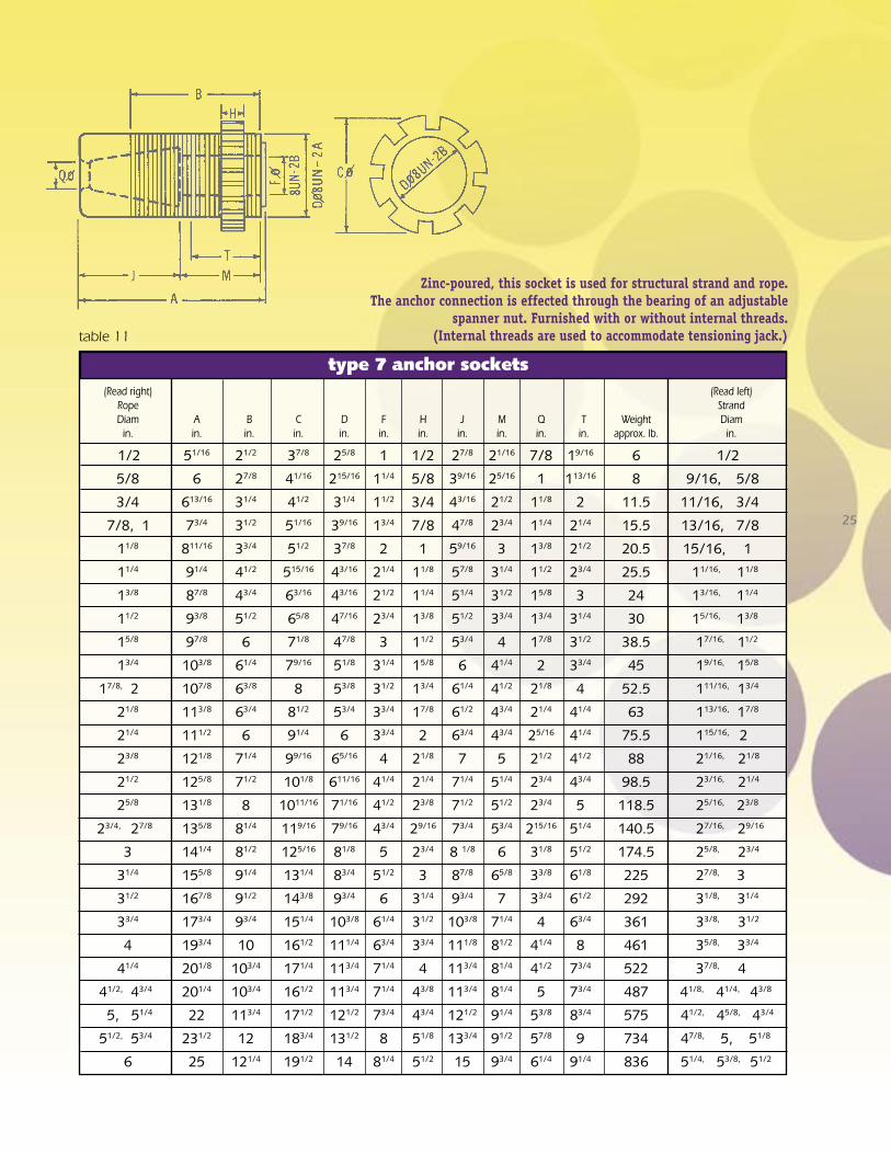
table 11
type 7 anchor sockets (Read right) (Read left) Rope Strand Diam A B C D F H J M Q T Weight Diam in. in. in. in. in. in. in. in. in. in. in. approx. lb. in.
1/2 51/16 21/2 37/8 25/8 1 1/2 27/8 21/16 7/8 19/16 6 1/2 5/8 6 27/8 41/16 215/16 11/4 5/8 39/16 25/16 1 113/16 8 9/16, 5/8 3/4 613/16 31/4 41/2 31/4 11/2 3/4 43/16 21/2 11/8 2 11.5 11/16, 3/4 7/8, 1 73/4 31/2 51/16 39/16 13/4 7/8 47/8 23/4 11/4 21/4 15.5 13/16, 7/8
11/8 811/16 33/4 51/2 37/8 2 1 59/16 3 13/8 21/2 20.5 15/16, 1
11/4 91/4 41/2 515/16 43/16 21/4 11/8 57/8 31/4 11/2 23/4 25.5 11/16, 11/8
13/8 87/8 43/4 63/16 43/16 21/2 11/4 51/4 31/2 15/8 3 24 13/16, 11/4
11/2 93/8 51/2 65/8 47/16 23/4 13/8 51/2 33/4 13/4 31/4 30 15/16, 13/8
15/8 97/8 6 71/8 47/8 3 11/2 53/4 4 17/8 31/2 38.5 17/16, 11/2
13/4 103/8 61/4 79/16 51/8 31/4 15/8 6 41/4 2 33/4 45 19/16, 15/8
17/8, 2 107/8 63/8 8 53/8 31/2 13/4 61/4 41/2 21/8 4 52.5 111/16, 13/4
21/8 113/8 63/4 81/2 53/4 33/4 17/8 61/2 43/4 21/4 41/4 63 113/16, 17/8
21/4 111/2 6 91/4 6 33/4 2 63/4 43/4 25/16 41/4 75.5 115/16, 2
23/8 121/8 71/4 99/16 65/16 4 21/8 7 5 21/2 41/2 88 21/16, 21/8
21/2 125/8 71/2 101/8 611/16 41/4 21/4 71/4 51/4 23/4 43/4 98.5 23/16, 21/4
25/8 131/8 8 1011/16 71/16 41/2 23/8 71/2 51/2 23/4 5 118.5 25/16, 23/8
23/4, 27/8 135/8 81/4 119/16 79/16 43/4 29/16 73/4 53/4 215/16 51/4 140.5 27/16, 29/16
3 141/4 81/2 125/16 81/8 5 23/4 8 1/8 6 31/8 51/2 174.5 25/8, 23/4
31/4 155/8 91/4 131/4 83/4 51/2 3 87/8 65/8 33/8 61/8 225 27/8, 3
31/2 167/8 91/2 143/8 93/4 6 31/4 93/4 7 33/4 61/2 292 31/8, 31/4
33/4 173/4 93/4 151/4 103/8 61/4 31/2 103/8 71/4 4 63/4 361 33/8, 31/2
4 193/4 10 161/2 111/4 63/4 33/4 111/8 81/2 41/4 8 461 35/8, 33/4
41/4 201/8 103/4 171/4 113/4 71/4 4 113/4 81/4 41/2 73/4 522 37/8, 4
41/2, 43/4 201/4 103/4 161/2 113/4 71/4 43/8 113/4 81/4 5 73/4 487 41/8, 41/4, 43/8
5, 51/4 22 113/4 171/2 121/2 73/4 43/4 121/2 91/4 53/8 83/4 575 41/2, 45/8, 43/4
51/2, 53/4 231/2 12 183/4 131/2 8 51/8 133/4 91/2 57/8 9 734 47/8, 5, 51/8
6 25 121/4 191/2 14 81/4 51/2 15 93/4 61/4 91/4 836 51/4, 53/8, 51/2
Zinc-poured, this socket is used for structural strand and rope. The anchor connection is effected through the bearing of an adjustable
spanner nut. Furnished with or without internal threads. (Internal threads are used to accommodate tensioning jack.)

26
table 12
type 8 anchor sockets (Read right) (Read left) Rope Strand Diam D J Q Weight Diam in. in. in. in. approx. lb. in.
1/2 25/8 27/8 7/8 2.5 1/2 5/8 215/16 39/16 1 4 9/16, 5/8 3/4 31/4 43/16 11/8 5.5 11/16, 3/4 7/8, 1 39/16 47/8 11/4 8 13/16, 7/8
11/8 37/8 59/16 13/8 10.5 15/16, 1
11/4 41/8 57/8 11/2 12.5 11/16, 11/8
13/8 4 51/4 15/8 10 13/16, 11/4
11/2 4 3/16 51/2 13/4 11 15/16, 13/8
15/8 41/2 53/4 17/8 13 17/16, 11/2
13/4 413/16 6 2 16.5 19/16, 15/8
17/8, 2 51/8 61/4 21/8 20 111/16, 13/4
21/8 51/2 61/2 21/4 24 113/16, 17/8
21/4 515/16 63/4 23/8 31 115/16, 2
23/8 65/16 7 21/2 37 21/16, 21/8
21/2 611/16 71/4 23/4 44 23/16, 21/4
25/8 71/16 71/2 23/4 53 25/16, 23/8
23/4, 27/8 7 9/16 73/4 215/16 62 27/16, 29/16
3 81/8 8 1/8 31/8 76 25/8, 23/4
31/4 83/4 87/8 33/8 99 27/8, 3
31/2 911/16 93/4 33/4 130 31/8, 31/4
33/4 103/8 103/8 4 161 33/8, 31/2
4 111/16 111/8 41/4 194 35/8, 33/4
41/4 113/4 113/4 41/2 233 37/8, 4
41/2, 43/4 113/4 113/4 51/4 227 41/8, 41/4, 43/8
5, 51/4 121/2 121/2 53/4 266 41/2, 45/8, 43/4
51/2, 53/4 131/2 133/4 61/4 339 47/8, 5, 51/8
6 14 15 61/2 390 51/4, 5 3/8, 51/2
Zinc-poured, this socket is used for structural strand and rope; this is a bearing-type socket. Its assembly length is adjusted
by shimming at the bearing surface.

bethlehem wire rope
6x19 Class General Purpose 6x36 Class General Purpose Rotation Resistant 8x19 Class, 19x7, 19x19 and 35x7 Drill line Tubing line Sand line Torpedo line Well measuring line (wire) Well servicing line 1x16 and 1x19 Roepac Roepac-T Crane Hoist Teleroepac Hammerline Galvanized rope Structural Rope and Assemblies bethlehem elevator rope
6x19 Class 8x19 Class Iron Grade Traction Grade Xtrac Grade
bethlehem structural strand & strand products
A-Coat Galvanized Strand B-Coat Galvanized Strand C-Coat Galvanized Strand Structural Strand Assemblies Guy Strand Round Wire Track Strand Hose Reinforcing Strand
standard product listThis is a partial list of Bethlehem Wire Rope, Strand and High Carbon Wire products manufac-tured by Wirerope Works, Inc. If you require an-other product which is not shown, please call our Customer Service Depart-ment at 1-800-541-7673 for assistance.
bethlehem mining rope
6x19 Class 6x36 Class 6x61 Class 8x36 Class Excavator Grade Excavator-AR Grade En-core Beth Pac Maxi-core Structural Strand Pendants Flattened Strand Rope
high carbon wireBright Wire .018”-.250” Rope Wire .018”-.250” Mechanical Spring Wire .018”-.200” Music Spring Wire 8ga-1/4” Pipewrapping Wire 8ga-1/4” Tankwrapping Wire
Patented Wire .024”-.200” for redraw .032”-.200” for flat rolling .032”-.200” for brushwire
Hot Dipped Galvanized .066”-.250” Structural Strand Wire .066”-.250” ACSR Wire

100 Maynard StreetWilliamsport, PA 17701 USA
Tel: 570-326-5146 International1-800-541-7673 Inside the U.S.
Fax: 570-327-4274www.wireropeworks.com
Manufacturer of
Bethlehem Wire Rope®