Syvecs FocusRS MK2 Manual · Ford Focus Rs Mk2 This document is intended for use by a technical...
6
Syvecs LTD V1.2 Ford Focus Rs Mk2 This document is intended for use by a technical audience and describes a number of procedures that are potentially hazardous. Installations should be carried out by competent persons only. Syvecs and the author accept no liability for any damage caused by the incorrect installation or configuration of the equipment. Please Note that due to frequent firmware changes certain windows might not be the same as the manual illustrates. If so please contact the Syvecs Tech Team for Assistance. [email protected]
Transcript of Syvecs FocusRS MK2 Manual · Ford Focus Rs Mk2 This document is intended for use by a technical...

Syvecs LTD
V1.2
Ford Focus Rs Mk2
This document is intended for use by a technical audience and describes a number of procedures that are potentially hazardous. Installations should be carried out by competent persons only.
Syvecs and the author accept no liability for any damage caused by the incorrect installation or configuration of the equipment.
Please Note that due to frequent firmware changes certain windows might not be the same as the manual illustrates. If so please contact the Syvecs Tech Team for Assistance.
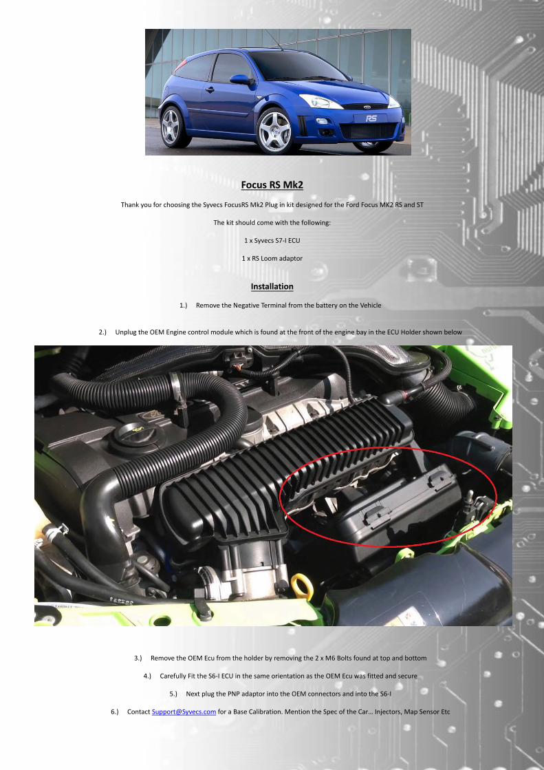
Focus RS Mk2
Thank you for choosing the Syvecs FocusRS Mk2 Plug in kit designed for the Ford Focus MK2 RS and ST
The kit should come with the following:
1 x Syvecs S7‐I ECU
1 x RS Loom adaptor
Installation
1.) Remove the Negative Terminal from the battery on the Vehicle
2.) Unplug the OEM Engine control module which is found at the front of the engine bay in the ECU Holder shown below
3.) Remove the OEM Ecu from the holder by removing the 2 x M6 Bolts found at top and bottom
4.) Carefully Fit the S6‐I ECU in the same orientation as the OEM Ecu was fitted and secure
5.) Next plug the PNP adaptor into the OEM connectors and into the S6‐I
6.) Contact [email protected] for a Base Calibration. Mention the Spec of the Car… Injectors, Map Sensor Etc

Focus MK2 RS Software Options
Reverse Lockout
The Reverse Lock out switch stops users from allowing Reverse to be selected when moving, this is adjusted in the Fan8 PWM Map or on Older Software via the Change light Strategy
MPG Scaling on Dash ‐Injector Size is set in Fuel Consumption Scaling
Map Switching
Adjusting the Calibration Switch position via the steering wheel controls is possible, In the Menu option you can change the Steering wheel Feel
Standard = Cal1 Sport = Cal2
Comfort = Cal3
TC Switch
TC Switch from OEM Car Come in on Slave AN20 which can be used for TC Select switching or other functions

Rev Matching and Flat Shift on Manual Transmission
Flat Shifting ‐ When the Clutch is pressed on it will send a GearCut Request into the ECU for Flat Shifting. This is Setup in Gearcut – Open Loop
Focus RS Mk2 FAQ and Help
Q) Do you control the OEM VVT
A) Yes, this is adjustable via Variable Valve timing calibrations, Can Change Intake and Exhaust Cam Targets
Q) Can we Flat Foot Shift
A) Yes, The gearcut strategy takes full care of the Torque Reductions on shifts and allows you to change gear while fully on throttle
Q) Can you Adjust the Launch
A) Yes, its fully adjustable in stage and after also where a Limiter can be set based on Time or Speed
Q) Do you Supply a Base map for the Kit
A) Yes as with all our kits we supply a very good base calibration to get everything working for you
Q) What of the original features will now not work?
A) None, even cruise control works but it doesn’t allow you to adjust speed on the stalk, only clamp a speed
Email [email protected] for a base map to suit your setup.
A DESCRIPTION
PART NUMBER
NOTES:
SyvecsDescription SyvecsPinout FocusRSNotes
PWR CTR OUT A1 Main Relay
H‐Bridge1 / SlaveOut1 A2 DBW H‐Bridge2 / SlaveOut2 A3 DBW H‐Bridge3 / SlaveOut3 A4
H‐Bridge4 / SlaveOut4 A5
H‐Bridge5 / SlaveOut5 A6
H‐Bridge6 / SlaveOut6 A7
H‐Bridge7 / SlaveOut7 A8
H‐Bridge8 / SlaveOut8 A9
FUEL1 A10 Primary Injector 1

FUEL2 A11 Primary Injector 2
FUEL3 A12 Primary Injector 3
FUEL4 A13 Primary Injector 4
FUEL5 A14 Primary Injector 5
FUEL6 A15 Reverse Gear Switch FUEL7 A16 Secondary Injector 1 Or Spare
Ouput FUEL8 A17 Secondary Injector 2 Or Spare
Ouput PWM1 /*FUEL9 A18 FUEL PUMP PWM2 / *FUEL10 A19 Fan PWM3 / *FUEL11 A20 Boost Solenoid 1&2 PWM4 / *FUEL12 A21 A/C Clutch
PWM5 A22 Start Rly PWM6 A23
PWM7 A24 VVT In PWM8 A25 VVT ex IGN1 A26 CYL 1 IGNITION OUTPUT
IGN2 A27 CYL 2 IGNITION OUTPUT
IGN3 A28 CYL 3 IGNITION OUTPUT
IGN4 A29 CYL 4 IGNITION OUTPUT
IGN5 A30 CYL 5 IGNITION OUTPUT
IGN6 A31
PWRGND A32 PwrGnd
PWRGND A33 PwrGNd
PWRGND A34 See End of Pinouts
B DESCRIPTION
PART NUMBER
NOTES:
PWRGND B1
B2
B3
KNOCK B4
KNOCK 2 B5
PVBAT B6
IVBAT B7
LAM1A B8
LAM1B B9
LAM1C B10
LAM1D B11
LAM1HEATER B12
IVBAT B13
LAM2A B14
LAM2B B15
LAM2C B16
LAM2D B17

LAM2HEATER B18
IVBAT B19
KLINE B20 Alternator Lin
RS232RX B21
RS232TX B22
LANRX- B23
LANRX+ B24
LANTX- B25
LANTX+ B26
C DESCRIPTION
PART NUMBER
NOTES:
KNOCK GROUND C1
ANGND C2
ANGND C3
ANGND C4
5V OUT C5
5V OUT C6
5V OUT C7
CAN L C8
CAN H C9
AN01 C10 Crank AN02 C11 Oil presure Switch AN03 C12 Map Sensor AN04 C13
AN05 C14 PPSa AN06 C15
AN07 C16 inlet cam sensor AN08 C17 Ex Cam AN09 C18 TPS INPUT AN10 C19
AN11 C20 TPS 2 INPUT AN12 C21
AN13 C22 COOLANT TEMP INPUT AN14 C23
AN15 C24 Air Temp AN16 C25 Fuel Pressure EGT1- C26
EGT1+ C27
PWR CTR IN C28 Ignition Switch
ANS1/ Slave An01 C29
ANS2 / Slave An02 C30
ANS3 / Slave An03 C31
ANS4 / Slave An04 C32
ANS5 / Slave An05 C33
ANS6 / Slave An06 C34