SYSTXCCITW01--A, SYSTXCCITN01--A &...
100
SYSTXCCITW01-- A, SYSTXCCITN01-- A & SYSTXCCITC01-- A Infinityr Touch Control Installation Instructions NOTE: Read the entire instruction manual before starting the installation. The features and functions outlined in the Installation Instructions reflect Version 11 software. See the Infinity Touch product page on the HVACPartner.com website or the Downloads section of the www.MyInfinityTouch.Carrier.com website for the latest software release. US Patents: Carrierr U.S. Pat No. 7,243,004, Carrierr U.S. Pat No. 7,775,452, pointSETt U.S. Pat No. 7,415,102
-
Upload
truongmien -
Category
Documents
-
view
219 -
download
4
Transcript of SYSTXCCITW01--A, SYSTXCCITN01--A &...

SYSTXCCITW01--A, SYSTXCCITN01--A& SYSTXCCITC01--AInfinityr Touch Control
Installation Instructions
NOTE: Read the entire instruction manual before starting the installation.
The features and functions outlined in the Installation Instructions reflect Version 11software. See the Infinity Touch product page on the HVACPartner.com website orthe Downloads section of the www.MyInfinityTouch.Carrier.com website for thelatest software release.
US Patents: Carrierr U.S. Pat No. 7,243,004, Carrierr U.S. Pat No. 7,775,452,pointSETt U.S. Pat No. 7,415,102


TABLE OF CONTENTSPAGE
1.Safety Considerations 1. . . . . . . . . . . . . . . . . . . . . . . . . . . . . . . . . . . . . . . . . . . . .
2.Introduction 1. . . . . . . . . . . . . . . . . . . . . . . . . . . . . . . . . . . . . . . . . . . . . . . . . . . . .
3.Quick Start 2. . . . . . . . . . . . . . . . . . . . . . . . . . . . . . . . . . . . . . . . . . . . . . . . . . . . . .
3.1. Set Time and Date 2. . . . . . . . . . . . . . . . . . . . . . . . . . . . . . . . . . . . . . . . . . . .
3.1.1. Manually Adjust Time and Date 3. . . . . . . . . . . . . . . . . . . . . . . . . . . .
3.1.2. Setup Time Zone 4. . . . . . . . . . . . . . . . . . . . . . . . . . . . . . . . . . . . . . . .
3.1.3. Enable Time Synchronization 4. . . . . . . . . . . . . . . . . . . . . . . . . . . . . .
3.2. Set Dealer Information 5. . . . . . . . . . . . . . . . . . . . . . . . . . . . . . . . . . . . . . . .
4.Installation 6. . . . . . . . . . . . . . . . . . . . . . . . . . . . . . . . . . . . . . . . . . . . . . . . . . . . . .
4.1. Overview 6. . . . . . . . . . . . . . . . . . . . . . . . . . . . . . . . . . . . . . . . . . . . . . . . . . .
4.2. Check Equipment 6. . . . . . . . . . . . . . . . . . . . . . . . . . . . . . . . . . . . . . . . . . . .
4.3. Location 7. . . . . . . . . . . . . . . . . . . . . . . . . . . . . . . . . . . . . . . . . . . . . . . . . . . .
4.3.1. Wall Control 7. . . . . . . . . . . . . . . . . . . . . . . . . . . . . . . . . . . . . . . . . . .
4.3.2. Remote Room Sensors 8. . . . . . . . . . . . . . . . . . . . . . . . . . . . . . . . . . .
4.3.2.1.Remote Room Sensor Averaging 8. . . . . . . . . . . . . . . . . . . . . . . . . . .
4.3.3. Smart Sensors (for zoning applications) 9. . . . . . . . . . . . . . . . . . . . . .
4.4. Wiring Considerations 9. . . . . . . . . . . . . . . . . . . . . . . . . . . . . . . . . . . . . . . . .
4.4.1. Shielded Wire 12. . . . . . . . . . . . . . . . . . . . . . . . . . . . . . . . . . . . . . . . .
4.4.2. Damper Control Module 13. . . . . . . . . . . . . . . . . . . . . . . . . . . . . . . . .

TABLE OF CONTENTS (cont.)PAGE
4.5. Mounting 13. . . . . . . . . . . . . . . . . . . . . . . . . . . . . . . . . . . . . . . . . . . . . . . . . .
4.5.1. Decorative Backplate 14. . . . . . . . . . . . . . . . . . . . . . . . . . . . . . . . . . .
4.6. Humidifier Connections 15. . . . . . . . . . . . . . . . . . . . . . . . . . . . . . . . . . . . . .
4.6.1. Bypass Humidifier 15. . . . . . . . . . . . . . . . . . . . . . . . . . . . . . . . . . . . . .
4.6.2. Fan Powered Humidifiers 15. . . . . . . . . . . . . . . . . . . . . . . . . . . . . . . .
5.Commissioning 16. . . . . . . . . . . . . . . . . . . . . . . . . . . . . . . . . . . . . . . . . . . . . . . . .
5.1. Searching for Indoor Unit 16. . . . . . . . . . . . . . . . . . . . . . . . . . . . . . . . . . . . .
5.2. Searching for Outdoor Unit 17. . . . . . . . . . . . . . . . . . . . . . . . . . . . . . . . . . . .
5.3. Indoor Evaporator Selection 18. . . . . . . . . . . . . . . . . . . . . . . . . . . . . . . . . . .
5.4. Electric Heater Selection 18. . . . . . . . . . . . . . . . . . . . . . . . . . . . . . . . . . . . . .
5.4.1. Hydronic Heat Application 19. . . . . . . . . . . . . . . . . . . . . . . . . . . . . . .
5.5. Searching SAM Module (If Applicable) 20. . . . . . . . . . . . . . . . . . . . . . . . . .
5.6. Searching for Zones (If Applicable) 20. . . . . . . . . . . . . . . . . . . . . . . . . . . . .
5.7. Filter Type Selection 21. . . . . . . . . . . . . . . . . . . . . . . . . . . . . . . . . . . . . . . . .
5.8. Humidifier Installation 21. . . . . . . . . . . . . . . . . . . . . . . . . . . . . . . . . . . . . . . .
5.9. Ultraviolet Lights Installation 21. . . . . . . . . . . . . . . . . . . . . . . . . . . . . . . . . .
5.10.Equipment Summary 21. . . . . . . . . . . . . . . . . . . . . . . . . . . . . . . . . . . . . . . .
5.11.Airflow Verification Check 22. . . . . . . . . . . . . . . . . . . . . . . . . . . . . . . . . . . .
5.12.Duct Assessment (zoning applications only) 22. . . . . . . . . . . . . . . . . . . . . .

TABLE OF CONTENTS (cont.)PAGE
6.Service Menu 24. . . . . . . . . . . . . . . . . . . . . . . . . . . . . . . . . . . . . . . . . . . . . . . . . . .
6.1. Equipment Summary 25. . . . . . . . . . . . . . . . . . . . . . . . . . . . . . . . . . . . . . . . .
6.2. Installation 25. . . . . . . . . . . . . . . . . . . . . . . . . . . . . . . . . . . . . . . . . . . . . . . . .
6.3. Set up 26. . . . . . . . . . . . . . . . . . . . . . . . . . . . . . . . . . . . . . . . . . . . . . . . . . . . .
6.3.1. Thermostat 27. . . . . . . . . . . . . . . . . . . . . . . . . . . . . . . . . . . . . . . . . . . .
6.3.1.1.Auto Mode set up 28. . . . . . . . . . . . . . . . . . . . . . . . . . . . . . . . . . . . . .
6.3.1.2.Heat/Cool Deadband 28. . . . . . . . . . . . . . . . . . . . . . . . . . . . . . . . . . .
6.3.1.3.Offsets 28. . . . . . . . . . . . . . . . . . . . . . . . . . . . . . . . . . . . . . . . . . . . . .
6.3.1.4.Reset factory defaults 29. . . . . . . . . . . . . . . . . . . . . . . . . . . . . . . . . . .
6.3.1.5.Scheduling Enable 29. . . . . . . . . . . . . . . . . . . . . . . . . . . . . . . . . . . . .
6.3.1.6.Smart Recovery Enable 29. . . . . . . . . . . . . . . . . . . . . . . . . . . . . . . . .
6.3.2. Fan Coil 29. . . . . . . . . . . . . . . . . . . . . . . . . . . . . . . . . . . . . . . . . . . . . .
6.3.2.1.Airflow 30. . . . . . . . . . . . . . . . . . . . . . . . . . . . . . . . . . . . . . . . . . . . . .
6.3.2.2.Altitude 31. . . . . . . . . . . . . . . . . . . . . . . . . . . . . . . . . . . . . . . . . . . . .
6.3.2.3.Fan Coil Dehumidification 31. . . . . . . . . . . . . . . . . . . . . . . . . . . . . . .
6.3.2.4.Fan Coil G--Terminal 32. . . . . . . . . . . . . . . . . . . . . . . . . . . . . . . . . . .
6.3.2.5.Fan Coil G--Terminal Alert 32. . . . . . . . . . . . . . . . . . . . . . . . . . . . . . .
6.3.2.6.Fan Coil G--Terminal Label 33. . . . . . . . . . . . . . . . . . . . . . . . . . . . . .

TABLE OF CONTENTS (cont.)PAGE
6.3.3. Furnace 34. . . . . . . . . . . . . . . . . . . . . . . . . . . . . . . . . . . . . . . . . . . . . .
6.3.3.1.Furnace Airflow 35. . . . . . . . . . . . . . . . . . . . . . . . . . . . . . . . . . . . . . .
6.3.3.2.AC/HP Air Flow 35. . . . . . . . . . . . . . . . . . . . . . . . . . . . . . . . . . . . . . .
6.3.3.3.Furnace Staging 36. . . . . . . . . . . . . . . . . . . . . . . . . . . . . . . . . . . . . . .
6.3.3.4.Furnace Airflow Limits (modulating furnace only) 36. . . . . . . . . . . .
6.3.3.5.Furnace Off Delay 37. . . . . . . . . . . . . . . . . . . . . . . . . . . . . . . . . . . . .
6.3.3.6.Altitude 37. . . . . . . . . . . . . . . . . . . . . . . . . . . . . . . . . . . . . . . . . . . . .
6.3.3.7.Furnace Dehumidifier Drain 38. . . . . . . . . . . . . . . . . . . . . . . . . . . . .
6.3.3.8.Furnace G Terminal 38. . . . . . . . . . . . . . . . . . . . . . . . . . . . . . . . . . . .
6.3.3.9.Furnace G Terminal Alert 39. . . . . . . . . . . . . . . . . . . . . . . . . . . . . . .
6.3.3.10.Furnace G Terminal Alert Label 39. . . . . . . . . . . . . . . . . . . . . . . . .
6.3.4. AC/Heat Pump 40. . . . . . . . . . . . . . . . . . . . . . . . . . . . . . . . . . . . . . . .
6.3.4.1.Latching 40. . . . . . . . . . . . . . . . . . . . . . . . . . . . . . . . . . . . . . . . . . . . .
6.3.4.2.Cooling Lockout 41. . . . . . . . . . . . . . . . . . . . . . . . . . . . . . . . . . . . . .
6.3.4.3.Defrost Interval 42. . . . . . . . . . . . . . . . . . . . . . . . . . . . . . . . . . . . . . .
6.3.4.4.Low Ambient Cooling 42. . . . . . . . . . . . . . . . . . . . . . . . . . . . . . . . . .
6.3.4.5.Quiet Shift 42. . . . . . . . . . . . . . . . . . . . . . . . . . . . . . . . . . . . . . . . . . .
6.3.4.6.AC/Heat Pump RPM Max 42. . . . . . . . . . . . . . . . . . . . . . . . . . . . . . .
6.3.4.7.Defrost Fan Delay 43. . . . . . . . . . . . . . . . . . . . . . . . . . . . . . . . . . . . .

TABLE OF CONTENTS (cont.)PAGE
6.3.4.8.Brownout Disable 43. . . . . . . . . . . . . . . . . . . . . . . . . . . . . . . . . . . . .
6.3.4.9.Low Air Multiplier 43. . . . . . . . . . . . . . . . . . . . . . . . . . . . . . . . . . . . .
6.3.4.10.Energy Efficiency 44. . . . . . . . . . . . . . . . . . . . . . . . . . . . . . . . . . . . .
6.3.5. Heat Source Lockout 44. . . . . . . . . . . . . . . . . . . . . . . . . . . . . . . . . . . .
6.3.6. Stages / Latch for 18VS 45. . . . . . . . . . . . . . . . . . . . . . . . . . . . . . . . . .
6.3.7. Zoning (If Applicable) 45. . . . . . . . . . . . . . . . . . . . . . . . . . . . . . . . . . .
6.3.7.1.Zoning Disable 45. . . . . . . . . . . . . . . . . . . . . . . . . . . . . . . . . . . . . . . .
6.3.7.2.Zone Offsets 46. . . . . . . . . . . . . . . . . . . . . . . . . . . . . . . . . . . . . . . . . .
6.3.7.3.Zone Airflow Limits 46. . . . . . . . . . . . . . . . . . . . . . . . . . . . . . . . . . . .
6.3.7.4.Duct Assessment Time 47. . . . . . . . . . . . . . . . . . . . . . . . . . . . . . . . . .
6.3.8. Accessories 47. . . . . . . . . . . . . . . . . . . . . . . . . . . . . . . . . . . . . . . . . . .
6.3.8.1.Filter 47. . . . . . . . . . . . . . . . . . . . . . . . . . . . . . . . . . . . . . . . . . . . . . . .
6.3.8.2.Humidifier 48. . . . . . . . . . . . . . . . . . . . . . . . . . . . . . . . . . . . . . . . . . .
6.3.8.3.Ultraviolet Lights 48. . . . . . . . . . . . . . . . . . . . . . . . . . . . . . . . . . . . . .
6.3.8.4.Ventilator 48. . . . . . . . . . . . . . . . . . . . . . . . . . . . . . . . . . . . . . . . . . . .
6.3.9. Utility Curtailment 49. . . . . . . . . . . . . . . . . . . . . . . . . . . . . . . . . . . . . .
6.3.10. Hydronic Airflow 50. . . . . . . . . . . . . . . . . . . . . . . . . . . . . . . . . . . . . .
6.4. Check out 50. . . . . . . . . . . . . . . . . . . . . . . . . . . . . . . . . . . . . . . . . . . . . . . . .
6.4.1. Electric Heat 51. . . . . . . . . . . . . . . . . . . . . . . . . . . . . . . . . . . . . . . . . .
6.4.2. Furnace 51. . . . . . . . . . . . . . . . . . . . . . . . . . . . . . . . . . . . . . . . . . . . . .

TABLE OF CONTENTS (cont.)PAGE
6.4.3. Hydronic 52. . . . . . . . . . . . . . . . . . . . . . . . . . . . . . . . . . . . . . . . . . . . .
6.4.4. Air Conditioning 52. . . . . . . . . . . . . . . . . . . . . . . . . . . . . . . . . . . . . . .
6.4.5. Heat Pump Heating 53. . . . . . . . . . . . . . . . . . . . . . . . . . . . . . . . . . . . .
6.4.6. Heat Pump Cooling 54. . . . . . . . . . . . . . . . . . . . . . . . . . . . . . . . . . . . .
6.4.7. Humidifier 54. . . . . . . . . . . . . . . . . . . . . . . . . . . . . . . . . . . . . . . . . . . .
6.4.8. Ventilator 55. . . . . . . . . . . . . . . . . . . . . . . . . . . . . . . . . . . . . . . . . . . . .
6.4.9. Zoning (If Applicable) 55. . . . . . . . . . . . . . . . . . . . . . . . . . . . . . . . . . .
6.4.9.1.Airflow Limits 55. . . . . . . . . . . . . . . . . . . . . . . . . . . . . . . . . . . . . . . .
6.4.9.2.Damper/Sensor Check 55. . . . . . . . . . . . . . . . . . . . . . . . . . . . . . . . . .
6.4.9.3.Zone Duct Assessment 56. . . . . . . . . . . . . . . . . . . . . . . . . . . . . . . . . .
6.4.9.4.Sensor Type 56. . . . . . . . . . . . . . . . . . . . . . . . . . . . . . . . . . . . . . . . . .
6.5. Service Information 56. . . . . . . . . . . . . . . . . . . . . . . . . . . . . . . . . . . . . . . . . .
6.5.1. Advanced Diagnostics 57. . . . . . . . . . . . . . . . . . . . . . . . . . . . . . . . . . .
6.5.2. Fan Coil Status 57. . . . . . . . . . . . . . . . . . . . . . . . . . . . . . . . . . . . . . . .
6.5.3. Furnace Status 58. . . . . . . . . . . . . . . . . . . . . . . . . . . . . . . . . . . . . . . . .
6.5.4. AC Status 58. . . . . . . . . . . . . . . . . . . . . . . . . . . . . . . . . . . . . . . . . . . . .
6.5.5. Heat Pump Status 59. . . . . . . . . . . . . . . . . . . . . . . . . . . . . . . . . . . . . .
6.5.6. Zoning Status 59. . . . . . . . . . . . . . . . . . . . . . . . . . . . . . . . . . . . . . . . . .
6.5.7. Last 10 System Events 60. . . . . . . . . . . . . . . . . . . . . . . . . . . . . . . . . . .

TABLE OF CONTENTS (cont.)PAGE
6.5.8. Run/Fault History 61. . . . . . . . . . . . . . . . . . . . . . . . . . . . . . . . . . . . . .
6.5.9. Model/Serial Numbers 61. . . . . . . . . . . . . . . . . . . . . . . . . . . . . . . . . . .
6.5.10. Service Phone Number 62. . . . . . . . . . . . . . . . . . . . . . . . . . . . . . . . . .
6.5.11. Energy Tracking 62. . . . . . . . . . . . . . . . . . . . . . . . . . . . . . . . . . . . . . .
6.6. Refrigerant Charging (Green Speed Only) 63. . . . . . . . . . . . . . . . . . . . . . . . .
6.6.1. Charging 63. . . . . . . . . . . . . . . . . . . . . . . . . . . . . . . . . . . . . . . . . . . . .
6.6.2. Pump down 64. . . . . . . . . . . . . . . . . . . . . . . . . . . . . . . . . . . . . . . . . . .
6.6.3. Evacuation 64. . . . . . . . . . . . . . . . . . . . . . . . . . . . . . . . . . . . . . . . . . . .
6.7. Refrigerant Charging 18VS 65. . . . . . . . . . . . . . . . . . . . . . . . . . . . . . . . . . . .
6.7.1. Charging 65. . . . . . . . . . . . . . . . . . . . . . . . . . . . . . . . . . . . . . . . . . . . .
6.7.2. Pump down 67. . . . . . . . . . . . . . . . . . . . . . . . . . . . . . . . . . . . . . . . . . .
6.7.3. Evacuation 67. . . . . . . . . . . . . . . . . . . . . . . . . . . . . . . . . . . . . . . . . . . .
6.7.4. EXV Position 68. . . . . . . . . . . . . . . . . . . . . . . . . . . . . . . . . . . . . . . . . .
6.8. Dealer Logo 68. . . . . . . . . . . . . . . . . . . . . . . . . . . . . . . . . . . . . . . . . . . . . . . .
6.9. Utility Event Setup 69. . . . . . . . . . . . . . . . . . . . . . . . . . . . . . . . . . . . . . . . . .
7.Wireless Setup 70. . . . . . . . . . . . . . . . . . . . . . . . . . . . . . . . . . . . . . . . . . . . . . . . . .
7.1. SYSTXCCITC01--A Model (only) 71. . . . . . . . . . . . . . . . . . . . . . . . . . . . . .
7.2. SYSTXCCITW01--A Model (only) 74. . . . . . . . . . . . . . . . . . . . . . . . . . . . . .
8.Appendix A -- Wiring Diagrams 79. . . . . . . . . . . . . . . . . . . . . . . . . . . . . . . . . . . .
NOTE: See the Owner’s Manual for information regarding software upgrades.


1
1. Safety Considerations
Improper installation, adjustment, alteration, service, maintenance, or use can causeexplosion, fire, electrical shock, or other conditions which may cause death,personal injury or property damage. Consult a qualified installer, service agency oryour distributor or branch for information or assistance. The qualified installer oragency must use factory--authorized kits or accessories when modifying this HVACsystem. Refer to the individual instructions packaged with the kits or accessorieswhen installing.
Follow all safety codes. Wear safety glasses, protective clothing, and work gloves.Have a fire extinguisher available. Read these instructions thoroughly and followall warnings and cautions included in literature and attached to the unit. Consultlocal building codes and the current edition of the National Electrical Code (NEC)NFPA 70. In Canada, refer to the current editions of the Canadian Electrical CodeCSA C22.1.
Recognize safety information. When you see this symbol on the unit and ininstructions or manuals, be alert to the potential for personal injury. Understand thesignal words DANGER, WARNING, and CAUTION. These words are used withthe safety--alert symbol. DANGER identifies the most serious hazards, which willresult in severe personal injury or death. WARNING signifies hazards, which couldresult in personal injury or death. CAUTION is used to identify unsafe practices,which may result in minor personal injury or product and property damage. NOTEis used to highlight suggestions which will result in enhanced installation,reliability, or operation.
2. Introduction
The Infinityr System consists of several intelligent communicating componentswhich include the Infinityr Touch Control (or User Interface), variable speedfurnace or FE fan coil, and 2--stage AC or HP, which continually communicate witheach other via a four--wire connection called the ABCD bus. Commands, operating

2
conditions, and other data are passed continually between components over theABCD bus. The result is a new level of comfort, versatility, and simplicity.
All Infinityr furnaces or fan coils are variable--speed and multi stage for maximumflexibility, efficiency, and comfort. They support controlled ventilation,humidification, dehumidification, and air quality control. Either an Infinityr(communicating), or a standard single--stage 24VAC controlled outdoor unit may beused.
When using conventional single--stage outdoor units, the Infinity furnace or fan coilprovides the 24 volt signals needed to control them. Also, the Infinityr NetworkInterface Module (P/N SYSTXCCNIM01) allows connection of a Carrier HRV orERV without the need for separate wall control.
When using a Carrier HRV or ERV with a zoned system, the Infinityr Zone boardallows connection of a Carrier HRV or ERV without the need for separate wallcontrol.
All system components are controlled through the wall mounted Infinity TouchControl, which replaces the conventional thermostat and provides the homeownerwith a single wall control for all features of the system.
3. Quick Start
3.1. Set Time and Date
The time and date can either be set manually or can be synchronized with the webserver (only for Wi--Fi enabled units). From the main screen, touch MENU, on thebottom of the control. The TIME/DATE icon will bring up the time and date menu.

3
A14215
3.1.1. Manually Adjust Time and Date
d To set the HOUR, MINUTE, MONTH, DAY, or YEAR touch the featureyou wish to change.
d Use the Up (Y) and Down (B) buttons to make the appropriate changes.
d When you have completed all of the settings touch SAVE.
A14216

4
3.1.2. Setup Time Zone
The time zone can be selected by selecting the setup time zone from the menu.Then select the time zone for the location. Time zones for both US and Canada areincluded.
A14217
3.1.3. Enable Time Synchronization
After setting up the time zone, the time synchronization can then be done. Bothsetting the time zone and enabling time synchronization must be done in order toenable time synchronization.

5
3.2. Set Dealer Information
From the main screen, touch MENU, on the bottom of the control. The SERVICEicon allows you to upload your contact information into the Infinity Touch Control.
A14219S Format your contact information and logo (if applicable) using the PC/MAC
application, save it to a standard USB drive. See Section 6.7.S Touch the SERVICE icon for about 10 seconds, then touch DEALER LOGO
UPLOAD.S Place the USB drive into the USB port on the bottom of the Infinity Touch
Control and follow the on screen prompts.S More detailed information can be found on HVACPartners.com under the
Product tab> Thermostats & Controls> SYSTXCCITW01> Documents &Downloads> Marketing/Miscellaneous> Infinity Touch Control Dealer LogoApplication -- Instructions.

6
4. Installation
4.1. Overview
This instruction covers installation of the Infinityr Touch Control and the InfinityrWireless Access Point only. Physical installation instructions for the indoor andoutdoor equipment, and accessories are provided with each unit.
Setup, commissioning, operation, and troubleshooting of the Infinityr System arecovered only in this installation instruction. It is the guide to connecting the systemcomponents and commissioning the system once all physical components areinstalled. Special screen prompts and start--up capabilities are provided in theInfinityr System to simplify and automate the initial commissioning of the system.S Install the Infinity Touch Control according to this instruction.S Install indoor unit, outdoor unit, and accessories according to their instructions.S Wire complete system according to this instruction.S Setup, commission, and operate system according to this instruction to assure a
smooth and trouble free start--up.
4.2. Check Equipment
Inspect equipment. File a claim with shipping company prior to installation ifshipment is damaged or incomplete.

7
4.3. Location
ELECTRICAL OPERATION HAZARD
Failure to follow this warning could result in personal injuryor death.
Disconnect power before routing control wiring.
! WARNING
All wiring must comply with national, local, and state codes.
4.3.1. Wall Control
The Infinity Touch Control is the command center for the Infinity System. It shouldbe located where it is easily accessible and visible to the adult homeowner or enduser. For accurate temperature measurement, the following guidelines should befollowed:
The Infinity Touch Control and Remote Room Sensors SHOULD be mounted:S Approximately 5--ft (1.5 m) from the floor.S Close to or in a frequently used room, preferably on an inside partitioning wall.S On a section of wall without pipes or ductwork.The Infinity Touch Control and Remote Room Sensors SHOULD NOT bemounted:S Close to a window, on an outside wall, or next to a door leading to the outside.S Exposed to direct light or heat from a lamp, sun, fireplace, or other
temperature--radiating objects which could cause a false reading.

8
S Close to or in direct airflow from supply registers.S In areas with poor air circulation, such as behind a door or in an alcove.
4.3.2. Remote Room Sensors
A Remote Room Sensor can be used with the Infinity Touch Control to take theplace of the control’s internal temperature sensor. This allows the Infinity TouchControl to be mounted in areas with less than optimal airflow (such as near anexterior door, window or in a closet). The remote sensor can be wired to theterminal block connectors labeled S1 and S2 at the control’s backplate, or the ZS1and ZS1C connection at the Damper Control Module. In either case, the InfinityTouch Control will automatically detect the Remote Room Sensor and ignore itsinternal temperature sensor.
4.3.2.1. Remote Room Sensor Averaging
Typically, one remote sensor is used but, multiple sensors may be used andaveraged in some applications. Averaging requires a special series--parallel wiringmethod with a specific number of sensors. See figure below. It is also important tonote the humidity sensor cannot be remotely located, so do not locate the InfinityControl in an area where humidity sensing may not be accurate.

9
Sensor 1 Sensor 2
Sensor 3 Sensor 4
Damper ControlModule
ZS_
Damper ControlModuleZS_C
A03233
4.3.3. Smart Sensors (for zoning applications)
Any zone may use a Smart Sensor. It provides a temperature display and buttons toadjust the desired temperature in that zone only. It also displays outdoortemperature and indoor humidity sensed at the control. Only one Smart Sensor maybe used per zone. They cannot be averaged like Remote Room Sensors. If a SmartSensor is used in a zone, a Remote Room Sensor may also be used in the samezone. The Remote Room Sensor has priority over the Smart Sensor. The SmartSensor will display the Remote Room Sensor temperature.
NOTE: Smart Sensors must be addressed to identify which zone it will control. SeeSmart Sensor Installation Instructions for details.
4.4. Wiring Considerations
Ordinary thermostat wire is recommended. Use 22 AWG or larger for normalwiring applications. Continuous wire lengths over 100 ft. should use 20 AWG orlarger.

10
NOTE: ABCD bus wiring only requires a four--wire connection; however, it isgood practice to run thermostat cable having more than four wires in the event of adamaged or broken wire during installation.
Each communicating device in the Infinityr Zone System has a four--pin connectorlabeled ABCD. It is recommended that the following color code be used whenwiring each device:
A — Green = Data AB — Yellow = Data BC — White = 24VAC (Com)D — Red = 24VAC (Hot)
A B C D
A03193
It is not mandatory that the above color code be used, but each ABCD connector inthe system MUST be wired consistently.
NOTE: Some outdoor units provide their own low--voltage power source and donot require the “C” (24VAC common) and “D” (24VAC power) connections. Seethe outdoor unit installation instructions for more information.
11
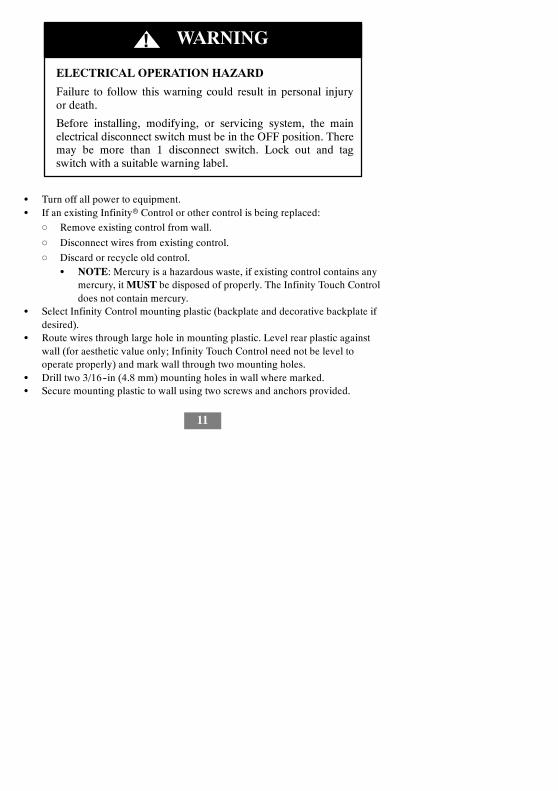
ELECTRICAL OPERATION HAZARD
Failure to follow this warning could result in personal injuryor death.
Before installing, modifying, or servicing system, the mainelectrical disconnect switch must be in the OFF position. Theremay be more than 1 disconnect switch. Lock out and tagswitch with a suitable warning label.
! WARNING
S Turn off all power to equipment.S If an existing Infinityr Control or other control is being replaced:
d Remove existing control from wall.
d Disconnect wires from existing control.
d Discard or recycle old control.S NOTE: Mercury is a hazardous waste, if existing control contains any
mercury, it MUST be disposed of properly. The Infinity Touch Controldoes not contain mercury.
S Select Infinity Control mounting plastic (backplate and decorative backplate ifdesired).
S Route wires through large hole in mounting plastic. Level rear plastic againstwall (for aesthetic value only; Infinity Touch Control need not be level tooperate properly) and mark wall through two mounting holes.
S Drill two 3/16--in (4.8 mm) mounting holes in wall where marked.S Secure mounting plastic to wall using two screws and anchors provided.

12
S Adjust length and routing of each wire to reach each wire entry on theconnector backplate. Strip 1/4--in (6.4 mm) of insulation from each wire.
S Match and connect thermostat wires to proper terminals on control backplate.d See wiring diagrams in Appendix A.
S Push any excess wire into the wall. Seal hole in wall to prevent any air leaks.Leaks can affect operation.
S Attach Infinity Control to the mounting plastic by lining up the plastic guideson the back of the control with the opening on the mounting plastic and pushon.
S Perform installation of all other system equipment (i.e. dampers, humidifier,ventilator, UV lights, etc.).
S Turn on power to equipment.
4.4.1. Shielded Wire
If the thermostat wiring will be located near or in parallel with high voltage wiring,radio, TV or Ethernet wiring, then four conductor, twisted--pair, shielded cable canbe used to reduce or eliminate potential interference. The shield wire should beconnected to the C terminal, or ground, at the indoor unit. The shield wire shouldNOT be connected to any terminal at the user interface. Connecting the shield toground at both ends can cause current loops in the shield, reducing shieldeffectiveness.
Connect one pair of the two--pair (minimum) cable to the A and B communicationterminals, and another pair to the C and D terminals at both ends of the cable. Theshield wire should ONLY be connected at the indoor equipment ground or Cterminal. Note that some outdoor units only require the A and B connections. Seethe outdoor unit installation instructions for more information.

13
4.4.2. Damper Control Module (zoning systems only)
All wiring is run back to the Damper Control Module. Select a location near thefurnace or fan coil where wiring from the control, each Remote Room Sensor orSmart Sensor, each damper actuator, and the equipment itself can come togethereasily. The Damper Control Module is approved for indoor use only and shouldnever be installed with any of its components exposed to the elements. The DamperControl Module (and zone dampers) may be installed in any area where thetemperature remains between --4_F to 158_F (--20_C to 70_C), and there is nocondensation. The cover must be installed to prevent damage from other sources.Do not locate where it will be accessible to children. It may be mounted in eithervertical or horizontal position. Remember that wiring access is likely the mostimportant consideration.
PERSONAL INJURY HAZARD
Failure to follow this caution may result in personal injury.
To prevent possible damage to the Damper Control Module,DO NOT mount on plenum, ductwork, or flush againstfurnace or fan coil.
CAUTION!
4.5. Mounting
First become familiar with all plastic assembly pieces shown on the following page.The Infinity Touch Control will snap together with the backplate. A backplate issupplied. Attach backplate using only a small hole in the wall allowing a four wireconnection to pass through. Mount the assembly to the backplate.

14
A12214
A12215
NOTE: Once Infinity Control is secured to wall with the backplate assembly(snapped together), care must be taken not to bend or break the interlocking tabswhen removing.
4.5.1. Decorative Backplate
Sold separately, a thin decorative backplate is available to hide any marks/screwholes left from the previous thermostat. This decorative backplate (or beauty ring)is used by snapping it onto the back of the mounting plate before securing the plateto the wall.

15
A12213
NOTE: Once the Infinity Touch Control is secured to wall with the backplateassembly (snapped together), care must be taken not to bend or break theinterlocking tabs when removing.
4.6. Humidifier Connections
A 24VAC bypass or fan powered humidifier may be installed.
NOTE: Do NOT use a traditional humidistat to control humidifier operation. If ahumidifier is installed, let the Infinity Touch Control operate humidifier.
4.6.1. Bypass Humidifier
A bypass humidifier should be wired directly to the furnace or fan coil HUM and24VAC COM terminals. The Infinity Control Touch will automatically energize theHUM output during a call for humidification.
4.6.2. Fan Powered Humidifiers
Most fan powered humidifiers produce internal 24VAC in order to energize upon aswitch or contact closure. For this application, a 24VAC N.O. Isolation Relay(DPST) MUST be used to prevent mixing the internal humidifier power with theindoor equipment transformer. Applying 24VAC isolation relay coil to furnace orfan coil HUM and COM terminals will allow the Infinity Touch Control to

16
automatically energize the HUM output during a call for humidification. The N.O.relay contacts will be used to energize the humidifier. See fan powered humidifierinstallation instructions for more details.
5. Commissioning
This section addresses initial power up (or commissioning) of a new InfinityrTouch Control. The control will communicate and identify all components in theInfinityr System. The following is a typical example for a communicatingvariable--speed furnace / fan coil with a 2--stage air--conditioner / heat pump(including HYBRIDHEATr dual fuel system).
5.1. Searching for Indoor Unit
The Infinity Touch Control will light up and begin the commissioning process bydisplaying “Searching for indoor unit”. This includes Infinityr small packagedproducts (SPP), with UI Version 8.0 software or later.
A12177
NOTE: If the Infinity--compatible indoor equipment (furnace or fan coil) cannot befound, the control will display “Indoor unit not found”. This MUST be correctedbefore the initial power up sequence can continue. Proceed to the next section,Searching for outdoor unit. If it is not corrected, the Infinity Touch Control will gointo its DEMO operating mode.

17
A12178
5.2. Searching for Outdoor Unit
The Infinity Touch Control will then proceed to communicate with the outdoor unitby displaying “Searching for outdoor unit”. This includes Infinityr small packagedproducts (SPP), with UI Version 8.0 software or later.
NOTE: If the outdoor unit cannot be found, the control will display “Outdoor unitnot found”.S Select the appropriate unit installed; then, touch NEXT.
d AC1Stage – 1--stage air conditioner
d *AC2Stage – 2--stage air conditioner
d *HP1Stage – 1--stage heat pump
d *HP2Stage – 2--stage heat pump
d None – No outdoor unit installed
NOTE: For small packaged products (SPP), the selection screen is not needed andwill not appear.S The installer will first be instructed to select the appropriate size of the outdoor
unit; then, touch SELECT.
*Network Interference Module (NIM) may be required for these selections to be displayed.

18
A13118
5.3. Indoor Evaporator Selection
If a furnace is installed with a variable capacity heat pump or an 18VS heat pump, ascreen will appear to select the installed indoor evaporator coil. This selection isused to adequately calculate the refrigerant charge required while in the heat pumpcharging screens under the Heat Pump Checkout menu (See Pg. 54). Select “other”for non--Carrier evaporators.
5.4. Electric Heater Selection
If the indoor equipment is a fan coil, the control will display “Searching for heater”until one is found. If the electric heater is not self--identifying, the select heaterscreen will appear. Touch the appropriate heater size; then, touch SELECT.

19
A13119
5.4.1. Hydronic Heat Application
The Infinity Touch Control supports 2 types of Hydronic Heat applications:
1. Hot water coil in combination with an FE fan coil and heat pump, or hotwater coil as sole heat source with an FE fan coil.
2. Non--zoned FE fan coil combined with radiant hot water heat.
In either application, a Hydronic Heat kit should be installed in place of an electricheater. See FE fan coil Product Data for accessory part number. The system willself--identify that hydronic heat has been installed during electric heater selection.The system will treat the hot water coil as either auxiliary heat in a heat pumpapplication, or the sole heat source. Setup options for Hydronic Heat applicationsare described in the setup section of this instruction.

20
A13117
5.5. Searching for SAM Module (If Applicable)
“Searching for SAM Module” will appear on the screen to determine if a SystemAccess Module, used for home automation only, is connected to the system.
The SYSTXCCSAM01 is not compatible with this control. The compatible modulesare SYSTXCCRCT01 and SYSTXCCRWF01. The SAM is used for homeautomation purposes. The Infinity Touch control must have at least Version 8 ornewer to be compatible with the SAM.
NOTE: For more information regarding the SAM Module, reference the latestversion of the application specification entitled “Carrier Communicating HVACSystem” (Version 2 or later), available on HVACpartners.com, or the SystemAccess Module Installation Instructions.
5.6. Searching for Zones (If Applicable)
“Zoning -- Searching” will appear on the screen to determine if any zones arepresent. The screen will show Zone 1, Zone 2, etc. and indicate all zones havingeither a Remote Room Sensor, or smart sensors associated with them. If the systemcontains smart sensors, they must be assigned a zone number before continuing.See the Smart Sensor Installation Instructions on how to assign Smart Sensors totheir respective zones. After each zone has been identified, touch NEXT.

21
A12185
5.7. Filter Type Selection
The installer will next be prompted to select the air filter type installed with theInfinity System. After the selection is made, touch NEXT.S Air Filter: 1--in. to 4--in. media filterS EAC: high voltage electronic air cleanerS Air Purifier: Infinityr or Performancet Air Purifier
5.8. Humidifier Installation
Next, the installer will be prompted to select whether a humidifier is installed in thesystem. Select YES or NO, then touch NEXT.
5.9. Ultraviolet Lights Installation
Next, the installer will be prompted to select whether ultraviolet lights are installedin the system. Select YES or NO, then touch NEXT.
5.10. Equipment Summary
The equipment summary screen will appear after accessories have been selected.This screen will give a summary of all equipment automatically found or manually

22
selected. If an incorrect selection was made, touch RE--INSTALL to restart theinstallation process.
Example: SPP Equipment Summary Screen
A13120
5.11. Airflow Verification Check
The airflow verification check screen will appear next. The system will perform anairflow verification check. This process will take about 1--1/2 minutes to complete.When completed, a screen will appear displaying the static pressure (in inches)across the equipment at the expected highest delivered airflow. If the blower RPMis greater than 1200, then a warning will appear, but equipment operation and theTrueSenset dirty filter detection operation will not be affected. When the airflowverification check is complete, touch NEXT.
NOTE: The airflow verification check occurs only at initial installation, or whenINSTALL is run in the INSTALL/SERVICE menu.
5.12. Duct Assessment (zoning applications only)
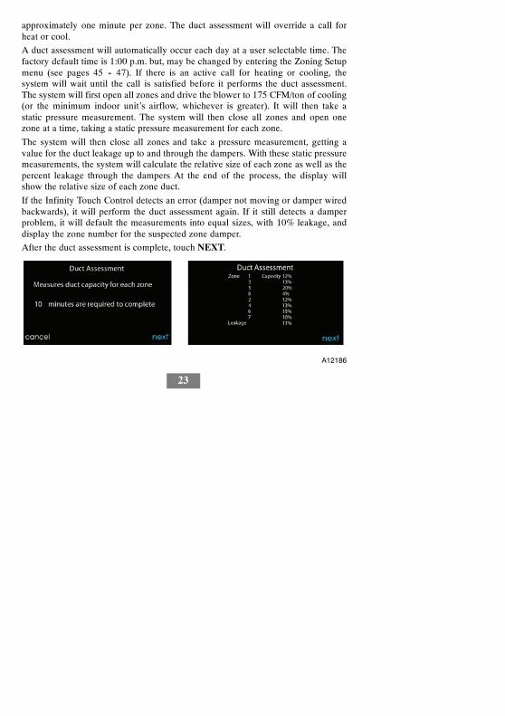
The duct assessment screen will be displayed next for zoning applications. TouchNEXT to start Duct Assessment. Duct Assessment will measure the relative size ofthe ductwork, up to and through the dampers. These measurements are used tocontrol the correct amount of airflow in the zoned system. Status messages willappear on the screen to indicate what the system is doing. The process will take
23
approximately one minute per zone. The duct assessment will override a call forheat or cool.
A duct assessment will automatically occur each day at a user selectable time. Thefactory default time is 1:00 p.m. but, may be changed by entering the Zoning Setupmenu (see pages 45 -- 47). If there is an active call for heating or cooling, thesystem will wait until the call is satisfied before it performs the duct assessment.The system will first open all zones and drive the blower to 175 CFM/ton of cooling(or the minimum indoor unit’s airflow, whichever is greater). It will then take astatic pressure measurement. The system will then close all zones and open onezone at a time, taking a static pressure measurement for each zone.
The system will then close all zones and take a pressure measurement, getting avalue for the duct leakage up to and through the dampers. With these static pressuremeasurements, the system will calculate the relative size of each zone as well as thepercent leakage through the dampers At the end of the process, the display willshow the relative size of each zone duct.
If the Infinity Touch Control detects an error (damper not moving or damper wiredbackwards), it will perform the duct assessment again. If it still detects a damperproblem, it will default the measurements into equal sizes, with 10% leakage, anddisplay the zone number for the suspected zone damper.
After the duct assessment is complete, touch NEXT.
A12186

24
6. Service Menu
The Service menus contain a set of vital information. This information enables theinstaller or service person to view a summary of what has been installed, etc. Thisinformation is not covered in the Owner’s Manual.
To enter service menus, touch menu, then touch and hold the SERVICE icon for atleast ten seconds. The following screens are available in installation and service. Toreturn to the previous screen, touch BACK. To exit the Service menus, touchDONE.
NOTE: See the Owner’s Manual for information regarding software upgrades.
NOTE: The user “selection of temperature units” affects the user screens only. Theservice screens use degree F only. The user “selection of temperature units” isunder the display icon on the main menu.
A14220

25
6.1. Equipment Summary
Touch EQUIPMENT SUMMARY to show indoor unit type and model number,outdoor unit type (and model number if a 2--stage unit), filter type, any accessoriesthat are installed, and the number of zones in the system. To return to the previousscreen, touch BACK. To exit the Service menus, touch DONE.
Example: SPP Equipment Summary Screen
A13121
6.2. Installation
Touch INSTALLATION to perform the start--up process in order to learn allequipment in system. Press right side button to initiate the process. Touch NEXT tobegin the process.
Touch Airflow Verification Test to perform a duct assessment. This can be done ifduct modifications have been made since installation of the UI. Duct assessmentcan be performed without performing a full system install.

26
A14222
NOTE: For Small Packaged Products (SPP), please use the following instructionsfor Set--up (Section 6.3), Checkout (Section 6.4), and Service (Section 6.5):
--For PAC AC Indoor and OAC HP Indoor, follow Fan Coil instructions.
--For Gas PAC Indoor and Gas PHP Indoor, follow Furnace instructions.
--For all PAC Outdoor, follow AC/Heat Pump instructions.
6.3. Set up
A13130
NOTE: Depending upon the equipment installed, the following options will bedisplayed.

27
S Indoor:d Furnace
d Fan coil
d PAC AC Indoor
d PAC HP Indoor
d GAS PAC Indoor
d GAS PHP IndoorS Outdoor:
d AC/Heat pump
d PAC AC outdoor
d PAC HP outdoor
d GAS PAC outdoor
d GAS PHP outdoor
Once the equipment has been selected, the appropriate menus will be displayed.
6.3.1. Thermostat
First touch SETUP, then touch THERMOSTAT to set up the parameters for theInfinityr Touch Control.
A13233
28
6.3.1.1. Auto Mode set up
Once the auto changeover option has been selected, touch SAVE.S Enable or Disable: Choose to enable or disable auto changeover mode
d Default = EnableS Auto changeover time: Adjustable from 5 to 120 minutes
d Default = 30 minutes
6.3.1.2. Heat/Cool Deadband
The minimum difference enforced between heating and cooling desiredtemperatures. The deadband does not change when the user changes betweenFahrenheit (_F) and Celsius (_C). Ex: A 2_ deadband will be 2_F or 2_C and doesnot change with units, _F and _C. This can allow one setting to “push” the other tomaintain this difference. When the correct deadband is set, touch SAVE.S Deadband: Adjustable from 0 to 6_F
d Default = 2_
6.3.1.3. Offsets
This option allows calibration (or deliberate miscalibration) of the temperature andhumidity sensors. These offsets are added to the actual temperature/humidityvalues. When the correct offsets are made, touch SAVE.S Outdoor temperature: Adjustable from --5 to 5_F (--3 to 3_C)
d Default = 0_FS Humidity: Adjustable from --10 – 10%
d Default = 0%

29
6.3.1.4. Reset factory defaults
This option allows the installer to reset certain factory parameters. After theselections are made, touch SAVE.S Program Schedule: Reset back to pre--programmed time and temperature.S User Settings: Reset user settings back to pre--programmed values.S Install Settings: Reset installation settings back to pre--programmed values.S Last 10 Faults: Reset the last 10 system faults under the Service menu.
6.3.1.5. Scheduling Enable
This option lets the installer allow programming features. After the selection ismade, touch SAVE.S Scheduling: On or Off
d Default = On
6.3.1.6. Smart Recovery Enable
Applies to programmable operation only. Will start recovery 90 minutes prior toschedule change in both heating and cooling mode. After the selection is made,touch SAVE.S Smart Recovery: On or Off
d Default = On
NOTE: The “Temperature Units Display” set--up section has been moved to theHomeowner Screens. See the Owner’s Manual for more information.
6.3.2. Fan Coil
First touch SETUP, then touch FAN COIL to set up the parameters for the fan coilunit.

30
A14223
6.3.2.1. Airflow
This option allows the installer to select the appropriate air flow based on the needsof the installation. The QUIET airflow means the minimum cooling airflow that thesystem can safely run (typically 300 CFM/ton). Use this setting if duct noise is asevere problem. Note that duct sweating in high humidity environments couldbecome an issue at low airflows. The COMFORT airflow means airflow is varieddepending on humidity and temperature demand settings. This selection enables thefull dehumidify and comfort capabilities of the system. The EFF325 airflow is afixed airflow used to achieve specified ratings – no dehumidification airflowreduction is performed. This is nominally 325 CFM/ton, but will vary if a 2--stageoutdoor unit is used. The EFF350 airflow is a fixed airflow used to achievespecified ratings – no dehumidification airflow reduction is performed. This isnominally 350 CFM/ton, but will vary if a 2--stage outdoor unit is used. The MAXairflow is a fixed 400 CFM/ton. No dehumidification airflow reduction isperformed.
The dehumidify airflow, when set to NORMAL, is allowed to adjust to a minimumto satisfy the dehumidification call. When set to HIGH, the minimum airflowduring the dehumidify mode is increased to reduce duct and register sweating. Alsothe airflow increases minimum airflow during normal cooling operation to helpreduce duct sweating.
31
After the selections are made, touch SAVE.S Cooling Airflow: Quiet, Comfort, EFF325, EFF350, or Max
d Default = ComfortS Dehumidify Airflow: Normal or High
d Default = Normal
6.3.2.2. AltitudeS Static Pressure selection: 0 to 10,000 feet. This is used to correct the static
pressure readings the system performs.
6.3.2.3. Fan Coil Dehumidification
The Dehum Drain Time option turns off the continuous fan at the end of cooling forfive minutes in order to drain the indoor coil of water. The fan will only be turnedoff if a dehumidify demand existed at the start of or during the cooling cycle.
The Electric Reheat option enables the electric heat to be used whilecool--to--dehumidify is running. This will allow the cool--to--dehumidify function torun longer, greatly improving humidity control in cooling mode. Accumulatedelectrical energy used while reheating (in kilowatt--hours) is shown on the Fan CoilRun Hours screen and can be reset there. This option is only available with fan coilsystems.
After the selections are made, touch SAVE.S Dehum Drain Time: Adjustable from 5 to 60 minutes or OFF
d Default = 15 minutesS Electric Reheat: Yes or No
d Default = No

32
6.3.2.4. Fan Coil G--Terminal
This setup option selects desired operation when the R to G contact is closed on thefan coil control board. Under this function option, fan turns on fan to selected fanspeed when G terminal is energized. Use the alert function to select the contactstate for an alert. Select Normally Open or Normally Closed, and then save yourselection. Shutdown shuts off fan and equipment when initiated. After theselections are made, touch Save.
A13229
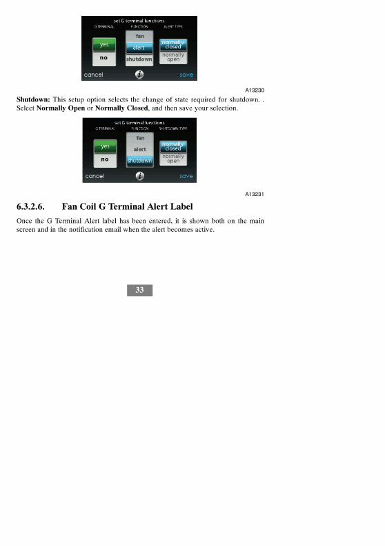
6.3.2.5. Fan Coil G--Terminal Alert
Use the alert function to select the contact state for an alert. Select Normally Openor Normally Closed, and then save your selection.
33
A13230
Shutdown: This setup option selects the change of state required for shutdown. .Select Normally Open or Normally Closed, and then save your selection.
A13231
6.3.2.6. Fan Coil G Terminal Alert Label
Once the G Terminal Alert label has been entered, it is shown both on the mainscreen and in the notification email when the alert becomes active.

34
A14224
6.3.3. Furnace
First touch SETUP, then touch FURNACE to set up the parameters for the furnaceunit.
A14225

35
6.3.3.1. Furnace Airflow
Selects the airflow of the furnace when heating. EFFICIENCY is the airflow usedto meet specified ratings, COMFORT is a decreased airflow used to increase theoutput air temperature and provide increased comfort.
For the Low heat rise option, set to ON if the system contains a bypass humidifier.The ON setting will increase the furnace low heat airflow.
After the selections are made, touch SAVE.S Furnace Air Flow: Comfort or Efficiency
d Default = ComfortS Low Heat Rise: On or Off
d Default = Off
6.3.3.2. AC/HP Air Flow
This option elects the airflow of the furnace when cooling, heat pump heating, anddehumidification.
The QUIET airflow means the minimum cooling airflow that the system can safelyrun (typically 300 CFM/ton). Use this setting if duct noise is a severe problem. Notethat duct sweating in high humidity environments could become an issue at lowairflows. The COMFORT airflow means airflow is varied depending on humidityand temperature demand settings. This selection enables the full dehumidify andcomfort capabilities of the system. The EFF325 airflow is a fixed airflow used toachieve specified ratings – no dehumidification airflow reduction is performed.This is nominally 325 CFM/ton, but will vary if a 2--stage outdoor unit is used. TheEFF350 airflow is a fixed airflow used to achieve specified ratings – nodehumidification airflow reduction is performed. This is nominally 350 CFM/ton,but will vary if a 2--stage outdoor unit is used. The MAX airflow is a fixed 400CFM/ton. No dehumidification airflow reduction is performed.
36
The dehumidify airflow, when set to NORMAL, the airflow is allowed to adjust toa minimum to satisfy the dehumidification call. When set to HIGH, the minimumairflow during the dehumidify mode is increased to reduce duct and registersweating. Also the airflow increases minimum airflow during normal coolingoperation to help reduce duct sweating.
After the selections are made, touch SAVE.S Cool: Quiet, Comfort, EFF325, EFF350, or Max
d Default = ComfortS HP Heat: Comfort or EFF350
d Default = ComfortS Dehumidify: Normal or High
d Default = Normal
6.3.3.3. Furnace Staging
This option controls the staging of the furnace and selects the minimum amount oftime low stage must operate before high stage is activated. SYSTEM setting willallow the Infinityr Zone Control to determine furnace staging. LOW will only runthe low stage of furnace heat. LOW--MED will run the low and medium stages (2stages of heat). MED will only run the medium stage of heat. MED--HIGH will runthe medium and high stages (2 stages of heat). HIGH will only run the high stageof furnace heat.
NOTE: Two--stage furnace has LOW and HIGH selections only.S Stages: System, Low, Low--Med, Med, Med--High, or High
d Default = System
6.3.3.4. Furnace Airflow Limits (modulating furnace only)
The following settings allow the installer to restrict the furnace within certainminimum and maximum airflows. These airflows are converted to capacities. The

37
Min and Max limits are determined by the equipment size. These settings are notthe same as the zoning airflow limits.S Min. modulating limits: Minimum CFM to run a modulating furnace. This will
increase the minimum operating capacity of the furnace.d Default value is the furnace air flow for the lowest heat capacity.
S Max. modulating limits: Maximum CFM to run a modulating furnace. Thiswill increase the maximum operating capacity of the furnace.d Default value is the furnace air flow for the highest heat capacity
6.3.3.5. Furnace Off Delay
This option denotes the amount of time the blower will continue to run after heatinghas shut off. After the selection is made, touch SAVE.S Furnace Off Delay: 90, 120, 150 or 180 seconds
d Default = 120 seconds
6.3.3.6. Altitude
For gas de--rating, this setting will adjust the furnace’s airflow to compensate foraltitude. Altitude adjustment is not available with older furnaces. Please see furnaceinstructions for further details. After the selection is made, touch SAVE.S Altitude: 0000 – 2000, US 2001 – 3000, CN 2100 – 4500, US 3001 – 4000,
US 4001 – 5000, US 5001 6000, US 6001 – 7000, US 7001 – 8000, US 8001 –9000, and US > 9000.d Default = US 2001--3000
S Static Pressure selection: 0 to 10,000 feet. This value is used to correct thestatic pressure readings the system performs.

38
6.3.3.7. Furnace Dehumidifier Drain
This option selects the time the continuous fan turns off at the end of cooling inorder to drain the indoor coil of water. The fan will only be turned off if adehumidify demand existed at the start of or during the cooling cycle.S Dehumidify Drain Time: Adjustable from 5 to 60 minutes
d Default = 15 minutes
6.3.3.8. Furnace G Terminal
This setup option selects desired operation when the R--G circuit changes state onthe furnace control board depending on setup.
Under the function option, FAN turns on fan to selected fan speed when G terminalis energized. SHUTDOWN shuts off fan and equipment when initiated.
After the selections are made, touch SAVE.S Function: Disabled, Fan or Shutdown
d Default = DisabledS Fan Speed: Low, Med, or High
d Default = LowS Shutdown:
d Normally Open
d Normally Closed\
d The shutdown function may not be immediate. Blower off delays, etc., willstill be used. The shutdown is not intended for commercial applications. Ifimmediate shutdown is required, provision must be made to remove powerto indoor unit.

39
6.3.3.9. Furnace G--Terminal Alert
Use the alert function to select the contact state for an alert. Select Normally Openor Normally Closed, and then save your selection.
A13230
Shutdown: This setup option selects the change of state required for shutdown. .Select Normally Open or Normally Closed, and then save your selection.
6.3.3.10 Furnace G Terminal Alert Label
Once the G Terminal Alert label has been entered, it is shown both on the mainscreen and in the notification email when the alert becomes active.
A14224

40
6.3.4. AC/Heat Pump
First touch SETUP, then touch AC/HEAT PUMP to set up the parameters for theAC/Heat Pump unit.
A14227
6.3.4.1. Latching
High Cool Latch
A13227

41
S System in Controld The system will decide which stage should be running to satisfy the cool-
ing demand.S High Cool
d Temperature above which only the high stage of cooling will be energized.S Only Low Cool
d The system will only run in low stage cooling.
High Heat Latch
A13228
S System in Controld The system will decide which stage should be running to satisfy the heating
demand.S High Heat
d Temperature below which only the high stage of heating will be energized.S Only Low Heat
d The system will only run in low stage heating.
6.3.4.2. Cooling Lockout
Outside temperature below which cooling will not be provided. After the selectionis made, touch SAVE.

42
S Cooling Lockout Temp: None, 45, 50 or 55 (_F)d Default = None
6.3.4.3. Defrost Interval
Time interval at which defrost cycles can occur on a heat pump. AUTO means thedefrost interval is optimized by the outdoor control. After the selection is made,touch SAVE.S Set Defrost Interval: 30, 60, 90, 120 minutes or AUTO
d Default = AUTO
NOTE: See Heat Pump Installation Instructions for Defrost Timing Interval whenusing AUTO Defrost.
6.3.4.4. Low Ambient Cooling
Selecting YES will enable the low ambient cooling operation in the outdoor unit.This setting is only available with communicating outdoor units and with CoolingLockout set to NONE. Low ambient kits are not needed with communicatingoutdoor units. After the selection is made, touch SAVE.S Low Ambient Cooling: Yes or No
d Default = No
6.3.4.5. Quiet Shift
This option turns on Quiet Shift function in 1--stage or 2--stage communicating heatpumps. After the selection is made, touch SAVE.
NOTE: This option is not available with variable speed heat pumps.S Quiet Shift: On or Off
d Default = Off

43
6.3.4.6. AC/Heat Pump RPM Max
Used with variable capacity heat pumps, this option clamps the operating speedof the heat pump to this maximum. Used to reduce operating noise while in highheating capacity. Reducing this value will reduce the heating capacity of the heatpump. After the selection is made, touch SAVE.S AC Heat Pump Max RPM: Adjustable from 4500 – 7000
d Default = 7000 RPM
6.3.4.7. Defrost Fan Delay
Turns on the outdoor unit fan at the end of a defrost cycle for approximately 12seconds. This helps to reduce any nuisance refrigerant noise caused by theswitching reversing valve. This setup is only available on communicating heatpumps. After the selection is made, touch SAVE.S Defrost Fan Delay: Yes or No
d Default = No
6.3.4.8. Brownout Disable
This option turns off the high voltage brownout detection function in the outdoorunit control. After the selection is made, touch SAVE.S Brownout Disable: On or Off
d Default = Off
6.3.4.9 Low Air Multiplier
Adjusts the airflow speed on non--communicating two--stage units. Choose 0.65 forunits with a Bristol compressor, choose 0.80 (default) for units with a Copelandscroll compressor.

44
6.3.4.10. Energy Efficiency
This option is used to input the published ratings of the installed air conditioner orheat pump as part of the energy tracking calculation. After the ratings are entered,touch SAVE.
6.3.5. Heat Source LockoutFirst touch SETUP, then touch HEAT SOURCE LOCKOUTS to set up theparameters for the AC/Heat Pump unit.
For hydronic heat applications, this option allows the installer to set the lockouttemperatures below the which only the hydronic coil will operate, and the lockouttemperature above which the hydronic coil will not operate. After the selections aremade, touch SAVE.
A12149S HP Lockout: Adjustable from --20 to 55_F (--28 to 13_C) or None
d Default = NoneS Furnace, Electric Heat or Hydronic Lockout: Adjustable from 15 to 55_F
(--9 to 13_C) or Noned Default = None
S Defrost with Furnace, Electric Heat or Hydronic: Yes or Nod Default = Yes

45
6.3.6. Stages / Latch for 18VSFor 18VS heat pumps, the cooling and heating stage/latch can be changed. Selectcooling or heating next to stages/latch. The maximum stage and the minimum stagecan be selected. The minimum selected stage can be locked--in or set based uponthe outside temperature.
A14228
6.3.7. Zoning (If Applicable)
First touch SETUP, then touch ZONING to set up the parameters for the zoningsystem (if applicable).
A12191

46
6.3.7.1. Zoning Disable
This option allows the installer to enable or disable zoning. After the selection ismade, touch SAVE.S Disable Zoning: Yes or No
d Default = No
6.3.7.2. Zone Offsets
This option allows actual temperature offset for each zone, allowing calibration (ordeliberate miscalibration) of each sensor. Use the Left (<) or Right (>) buttons tochange the zone. After the selection is made, touch SAVE.S Temperature Offset: Adjustable between --5 to 5_F (--3 to 3_C)
d Default = 0_F
6.3.7.3. Zone Airflow Limits
Since a bypass damper is prohibited in this system, this setting is used to select themaximum allowable noise/airflow relationship into each zone based on air noiseand comfort requirements. LOW means 100% of maximum assessed airflow;MED--LOW means 138% of maximum assessed airflow; MEDIUM means 176%of maximum assessed airflow; MED--HIGH means 214% of maximum assessedairflow; HIGH means 250% of maximum assessed airflow; and NO LIMIT meansthe equipment does not stage down.
CFM associated for each limit is shown on the screen. Compare this value with theequipment’s low stage CFM value to ensure that equipment will run for each zone.Assessed airflow is determined as described in DUCT ASSESSMENT.
After the selections are made, touch SAVE.S Touch the zone name that you wish to changeS Select the zone to adjust airflow: Low, Med--Low, Medium, Med--High, High,
or No Limit

47
d Default = High
6.3.7.4. Duct Assessment Time
This option allows the installer to select the time in which the duct assessment willbe performed. After the selection is made, touch SAVE.S Duct Assessment Time: Selectable between 12 AM and 11PM
d Default = 1 PM
6.3.8. Accessories
First touch SETUP, then touch ACCESSORIES to set up the parameters for theaccessories installed with the system.
A12192
6.3.8.1. Filter
With this option, the installer has the option of selecting pressure monitoring, thetype of filter installed, and the time interval for cleaning. After the selections aremade, touch SAVE.S Pressure Monitoring (not available with Electric Air Cleaner): Enable or
Disabled Default = Enable

48
S Clean Interval: Selectable from 1 to 18 monthsd Default = 3 months
S Filter Type: Air Filter, Electric Air Cleaner or Air Purifierd Filter type is selected during installation; otherwise default = air filter
6.3.8.2. Humidifier
With this option, the installer has the option of selecting whether a humidifier isinstalled, to humidify with the fan in low speed, and the time interval for changingthe humidifier pad. After the selections are made, touch SAVE.S Humidifier Installed: Yes or No
d Humidifier selection made during installation; otherwise default = noS Change Pad: Selectable from 1 to 24 months
d Default = 12 monthsS Humidify with Fan: Yes or No
d Default = No
6.3.8.3. Ultraviolet Lights
With this option, the installer has the option of selecting whether ultraviolet lightsare installed, and the time interval for changing the ultraviolet lights. After theselections are made, touch SAVE.S UV Lights Installed: Yes or No
d UV Lights selection made during installation; otherwise default = noS Change Interval: Selectable from 1 to 48 months
d Default = 12 months
6.3.8.4. Ventilator
When a ventilator is installed, the installer has the option of selecting the timeinterval for cleaning the ventilator. After the selections are made, touch SAVE.

49
S Clean Interval: Selectable from 60, 90, 120, 150 or 180 daysd Default = 90 days
6.3.9. Utility Curtailment
Utility Saver is used to force the equipment to a lower stage (low or off) whenactivated by the utility company, typically during peak load times. This setup isavailable only if the equipment has a utility saver input (refer to outdoor equipmentInstallation Instructions). This setup controls the response of the equipment whenthe utility saver input is active. DISABLED means that the curtailment function isnot active. TURN OFF means the outdoor unit is to be turned off when thecurtailment function is active. LOW STAGE means the outdoor unit will run inlows stage when the curtailment function is active. After the selections are made,touch SAVE.
A12193
S Cooling: Disabled, Low Stage or Turn offd Default = Disabled
S Heat Pump: Disabled, Low Stage or Turn offd Default = Disabled

50
6.3.10. Hydronic Airflow
This option allows the installer to select the airflow for the fan coil when pairedwith a hydronic coil. After the selections are made, touch SAVE.
A12194S Airflow: Selectable between Off to Max in 50 CFM increments
d Off = 450 CFM, MAX = (odu_size in KBTU * 400) / 12)
d Default = Off
NOTE: Selected airflow used during hydronic heating is a fixed value, it does notvary.S Blower On Delay: Selectable from 0 to 240 seconds
d Default = 30 secondsS Blower Off Delay: Selectable from 0 to 240 seconds
d Default = 0 seconds
6.4. Check out
Touch CHECKOUT to view the equipment installed in the system. Performcheckout test to make sure each piece of equipment is operating properly.

51
A13122
6.4.1. Electric Heat
If you have a fan coil with electric heaters, this menu item will allow the heaters tobe exercised. With self--identifying electric heaters, three stages of electric heat areavailable to be exercised in any combination. Non--identifying heaters will onlyprovide one stage of heat. After the selections are made, touch START.S Low Heat: Selectable from 0 to 120 minutes
d Default = 5 minutesS Medium Heat: Selectable from 0 to 120 minutes
d Default = 5 minutesS High Heat: Selectable from 0 to 120 minutes
d Default = 5 minutes
6.4.2. Furnace
Make sure the furnace is properly installed.
This option allows the furnace to be exercised. First, a low heat run time and highheat run time are selected. The furnace will execute its ignition start--up sequence.This sequence will be displayed on the screen. After the gas valve and blower

52
motor turn on, the screen will show the current operating status of the furnace. Afterthe selections are made, touch START.S Low Heat: Selectable from 0 to 120 minutes
d Default = 5 minutesS High Heat: Selectable from 0 to 120 minutes
d Default = 5 minutes
6.4.3. Hydronic
This option allows the hydronic heat relay to be exercised. First, it will energize therelay and turns on the blower. This sequence will be displayed on the screen. Afterthe selections are made, touch START.S Hydronic heater check: Selectable from 0 to 120 minutes
d Default = 5 minutes
6.4.4. Air Conditioning
This option allows the air conditioner to be exercised. With a 2--stage AC unit, alow cool and a high cool run time are independently selectable to exercise. Thedisplay will change to show the AC operating status. After the selections are made,touch START.
For 18VS heat pumps, you can select the stage at which the heat pump willexercise. During the checkout, the stage and time can be changed by pressing theChange button on the checkout status screen.
NOTE: Airflows during Checkout modes are fixed to the EFFICIENCY settingand are independent of other airflow settings. To view airflows for normal airconditioning cooling mode, exit the CHECKOUT screen and apply a heatingdemand to the system.S Low Cool Run Time: Selectable from 0 to 120 minutes
d Default = 5 minutes
53
S High Cool Run Time: Selectable from 0 to 120 minutesd Default = 5 minutes
6.4.5. Heat Pump Heating
The heat pump heating mode can be exercised with this menu option. With a2--stage heat pump, a Low Heat and a High Heat Run Time are independentlyselectable to exercise.
For variable speed heat pumps, you can select the speed at which the heat pumpwill exercise.
For 18VS heat pumps, you can select the stage at which the heat pump willexercise. During the checkout, the stage and time can be changed by pressing theChange button on the checkout status screen.
After the selections are made, touch START.
NOTE: Airflows during Checkout modes are fixed to the EFFICIENCY settingand are independent of other airflow settings. To view airflows for normal airconditioning cooling mode, exit the CHECKOUT screen and apply a heatingdemand to the system.S Low Heat Run Time: Selectable from 0 to 120 minutes
d Default = 5 minutesS High Heat Run Time: Selectable from 0 to 120 minutes
d Default = 5 minutesS Speed (variable speed heat pump only): Selectable from lowest available to
100%d Default = lowest available as specified by variable speed heat pump
S Defrost: Yes or Nod Default = No

54
6.4.6. Heat Pump Cooling
The heat pump cooling mode can be exercised with this menu option. With a2--stage heat pump, a Low Cool Run Time and a High Cool Run Time areindependently selectable to exercise.
For variable speed heat pumps, you can select the speed at which the heat pumpwill exercise.
For 18VS heat pumps, you can select the stage at which the heat pump willexercise. During the checkout, the stage and time can be changed by pressing theChange button on the checkout status screen.
After the selections are made, touch START.
NOTE: Airflows during Checkout modes are fixed to the EFFICIENCY settingand are independent of other airflow settings. To view airflows for normal airconditioning cooling mode, exit the CHECKOUT screen and apply a heatingdemand to the system.S Low Cool Run Time: Selectable from 0 to 120 minutes
d Default = 5 minutesS High Cool Run Time: Selectable from 0 to 120 minutes
d Default = 5 minutesS Speed (variable speed heat pump only): Selectable from lowest available to
100%d Default = lowest available as specified by variable speed heat pump
6.4.7. Humidifier
The humidifier can be exercised On and Off with this menu option. To end thehumidifier checkout, touch STOP.S Humidifier Check: On or Off

55
6.4.8. Ventilator
The ventilator can be exercised through all of its operating speeds with this menuoption. To end the ventilator checkout, touch STOP.S Humidifier Check: High, Low or Off
6.4.9. Zoning (If Applicable)
6.4.9.1. Airflow Limits
Because there is no bypass damper, the zone airflow limit check will allow theinstaller to assess the airflow noise generated by the system providing themaximum amount of airflow to each zone. Touch AIRFLOW LIMITS: WhenSTART is touched, the selected zone’s damper will fully open, all others will close,and the indoor unit will provide the maximum airflow for that zone (as selected inSETUP — ZONING, Airflow Limits). If the airflow noise is objectionable, theinstaller can select a lower airflow noise limit. If the noise is not objectionable, theinstaller should leave HIGH selected, or even NO LIMIT.
NOTE: Selecting a lower airflow noise limit may decrease the homeowner’scomfort in that zone.
Touch the Left (<) or Right (>) buttons to change the desired zones. Once theproper airflow limits are set, touch SAVE, to see ZONING CHECKOUT menu.
6.4.9.2. Damper/Sensor Check
The Sensor/Damper Check allows the installer to check each zone damper foroperation, as well as insure the zone sensor corresponds to that particular zone.When first initiated, the Zone 1 damper will fully open, and all other zones willclose. Using the Left (<) or Right (>) buttons, the installer can select each zone andverify the damper is fully open while all other dampers remain closed.

56
After proper damper operation has been verified, the installer can now check andverify that each Remote Room Sensor corresponds to the proper zone damper in thesame zone. For systems with remote room sensor, temporarily disconnect any otherzone Remote Room Sensor (at sensor location). That zone damper will now open,while the Zone 1 damper will close.
For systems using Smart Sensors, the installer may press and hold the Hold andMode buttons simultaneously for 3 seconds to change the zone under test. Thisshould be done with each zone to verify that the zone sensor corresponds to thatparticular zone.
Once each zone has been checked, touch DONE to return to the ZONINGCHECKOUT menu.
6.4.9.3. Zone Duct Assessment
This screen shows the results from the previous duct assessment. The ductassessment is performed at initial start--up and at 1 P.M. or the installer selected timeeach day. If another duct assessment is desired, the service technician shouldperform a re--install of the system.
NOTE: A Duct Assessment will automatically occur every 24 hours at selectedtime to check system static and calibrate dampers.
Once the duct assessment is complete, touch DONE to return to the ZONINGCHECKOUT menu.
6.4.9.4. Sensor Type
This option shows a list of all zones with corresponding sensor types.
6.5. Service Information
The Service Info menu will only show the equipment installed in the system. Toenter this menu of options, touch SERVICE INFORMATION.
57
A13123
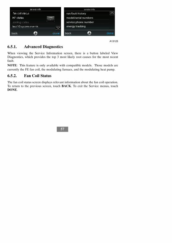
6.5.1. Advanced Diagnostics
When viewing the Service Information screen, there is a button labeled ViewDiagnostics, which provides the top 3 most likely root causes for the most recentfault.
NOTE: This feature is only available with compatible models. Those models arecurrently the FE fan coil, the modulating furnace, and the modulating heat pump.
6.5.2. Fan Coil Status
The fan coil status screen displays relevant information about the fan coil operation.To return to the previous screen, touch BACK. To exit the Service menus, touchDONE.

58
A12197
6.5.3. Furnace Status
The furnace status screen displays relevant information about the furnace operation.To return to the previous screen, touch BACK. To exit the Service menus, touchDONE.
A12198
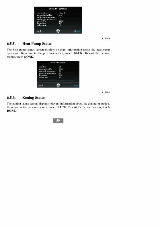
6.5.4. AC Status
The AC status screen displays relevant information about the AC operation. Toreturn to the previous screen, touch BACK. To exit the Service menus, touchDONE.
59
A12199
6.5.5. Heat Pump Status
The heat pump status screen displays relevant information about the heat pumpoperation. To return to the previous screen, touch BACK. To exit the Servicemenus, touch DONE.
A12200
6.5.6. Zoning Status
The zoning status screen displays relevant information about the zoning operation.To return to the previous screen, touch BACK. To exit the Service menus, touchDONE.

60
A12201
6.5.7. Last 10 System Events
This screen will show the last 10 events that occurred throughout the system. Eachentry has the time and date incident recorded. These events are stored in thememory of the control and are resettable in the THERMOSTAT SETUP screenunder the RESET FACTORY DEFAULT selection. Each entry shows theequipment that generated the event. To return to the previous screen, touch BACK.To exit the Service menus, touch DONE.
A12151

61
6.5.8. Run/Fault History
This information is stored in the equipment circuit boards (if communicating) anddisplayed on the control. The indoor unit and outdoor unit (if communicating) havethe following histories. To return to the previous screen, touch BACK. To exit theService menus, touch DONE.S Resettable Faults: Fault counters for each piece of equipment that can be reset.S Cycle Counters: Number of heat/cool/power cycles the unit has performed.S Run Times: Lifetime hours of operation in heating, cooling, and how long the
unit has been powered.
A12202
6.5.9. Model/Serial Numbers
This menu item allows the installer to view the model number, serial number (ifavailable), and control software version (if available) of all communicating piecesof equipment in the system, including the wall control. This information resides inthe original equipment circuit board(s) from the factory. If an equipment circuitboard has been replaced, the model and serial number will no longer be displayed.To return to the previous screen, touch BACK. To exit the Service menus, touchDONE.

62
A14230
6.5.10. Service Phone Number
This menu item allows the installer to view the name and phone number that thehomeowner can call for future service of the system. This name and phone numberwill appear to the homeowner whenever a service reminder pop--up message isdisplayed (i.e. Change Filter, etc.). To return to the previous screen, touch BACK.To exit, touch DONE. See Section 6.7.
6.5.11. Energy Tracking
This menu item allows the installer to view the energy usage of each piece ofequipment connected to the system. To return to the previous screen, touch BACK.To exit the Service menus, touch DONE.
A14231

63
6.6. Refrigerant Charging (Green Speed Only)
For variable speed heat pumps, a refrigerant charging menu is available to aid in theproper charging of the system. Enter the menu from the service screens by touchingREFRIGERANT CHARGING.
A12204
6.6.1. Charging
Within the CHARGING screens, the installer will have the ability to enter theLINESET length and the VAPOR LINE diameter. After the selections are made,touch NEXT.S Lineset: Selectable from 5 to 200 feetS Vapor line: Selectable with various diameters by using the up and down
buttonsNext, the installer will enter the WEIGH IN screen to verify the current total chargeis accurate. Once the installer has confirmed, touch DONE.
Next, the installer will enter the SERVICE VALVE SUBCOOL screen. This screenwill show the current liquid line subcool target (in _F). To begin the charging, touchSTART. If the outdoor temperatures are not in the required range, Service ValveSubcool may not be available.

64
Next, the installer will enter the SERVICE VALVE INFORMATION screen. Thecurrent liquid line subcool target, stabilization time, mode and speed in rpm, EXVposition in percent, indoor airflow in CFM, outdoor coil temperature in _F, indoortemperature in _F, outdoor temperature in _F, compressor discharge pressure inpsig, and accumulator suction pressure in psig are displayed on this screen. Oncethe stabilization time has expired, touch DONE.
6.6.2. Pump down
Because this system has an inverter controlled compressor, suction pressuretransducer and EXV, conventional procedure cannot be used to “pump down” andisolate the refrigerant into the outdoor unit. The control has provisions to assist inperforming this function.S Select mode to pump down in (COOL or HEAT). COOL mode allows
refrigerant to be isolated in outdoor unit. HEAT mode allows the refrigerant tobe isolated in indoor coil and lineset. Set desired time period.d Default time period for procedure is 120 minutes.
S Touch START to begin the pump down process. Unit will begin running inselected mode after a brief delay.
6.6.3. Evacuation
Because this system has an EXV for the heating expansion device, additional stepsmust be taken to open the EXV if the heat pump unit must be evacuated for servicereasons. If the EXV is not open when pulling a vacuum or recovering refrigerantfrom the heat pump unit, extended evacuation time may be required and/orinadequate vacuum obtained. The control has provisions to open the EXV forrefrigerant recovery and/or evacuation.S Set desired time period.
d Default time period for procedure is 120 minutes.S Touch START on UI to open the valve.

65
S Begin evacuation or refrigerant recovery as required for the procedure aftercontrol indicates the EXV is open. Power may be removed from heat pumpafter the control indicates “READY TO EVACUATE.”
6.7. Refrigerant Charging 18VS
For variable speed heat pumps, a refrigerant charging menu is available to aid in theproper charging of the system. Enter the menu from the service screens by touchingREFRIGERANT CHARGING.
A14232
6.7.1. Charging
Within the CHARGING COOLING or HTG CHECK screens, the installer willhave the ability to enter the LINESET length and the VAPOR LINE diameter.After the selections are made, touch NEXT.S Lineset: Selectable from 5 to 200 feetS Vapor line: Selectable with various diameters by using the up and down
buttonsNext, the installer will enter the WEIGH IN screen to verify the current total chargeis accurate. Once the installer has confirmed, touch DONE.

66
Next, the installer will enter the SERVICE VALVE SUBCOOL screen. This screenwill show the current liquid line subcool target (in _F). To begin the charging, touchSTART. If the outdoor temperatures are not in the required range, Service ValveSubcool may not be available.
Next, the installer will enter the SERVICE VALVE INFORMATION screen. Thecurrent liquid line subcool target, stabilization time, mode and speed in rpm, EXVposition in percent, indoor airflow in CFM, outdoor coil temperature in _F, indoortemperature in _F, outdoor temperature in _F, compressor discharge pressure inpsig, and accumulator suction pressure in psig are displayed on this screen. Oncethe stabilization time has expired, touch DONE.
A14286
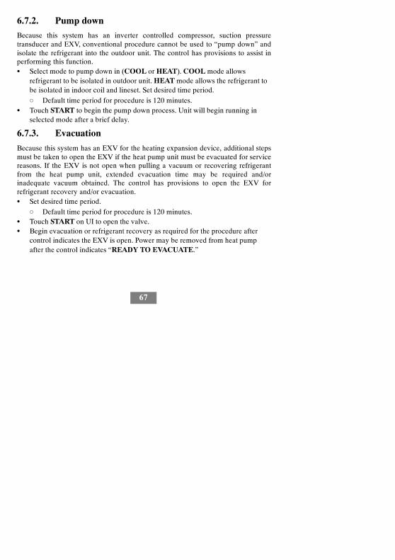
67
6.7.2. Pump down
Because this system has an inverter controlled compressor, suction pressuretransducer and EXV, conventional procedure cannot be used to “pump down” andisolate the refrigerant into the outdoor unit. The control has provisions to assist inperforming this function.S Select mode to pump down in (COOL or HEAT). COOL mode allows
refrigerant to be isolated in outdoor unit. HEAT mode allows the refrigerant tobe isolated in indoor coil and lineset. Set desired time period.d Default time period for procedure is 120 minutes.
S Touch START to begin the pump down process. Unit will begin running inselected mode after a brief delay.
6.7.3. Evacuation
Because this system has an EXV for the heating expansion device, additional stepsmust be taken to open the EXV if the heat pump unit must be evacuated for servicereasons. If the EXV is not open when pulling a vacuum or recovering refrigerantfrom the heat pump unit, extended evacuation time may be required and/orinadequate vacuum obtained. The control has provisions to open the EXV forrefrigerant recovery and/or evacuation.S Set desired time period.
d Default time period for procedure is 120 minutes.S Touch START on UI to open the valve.S Begin evacuation or refrigerant recovery as required for the procedure after
control indicates the EXV is open. Power may be removed from heat pumpafter the control indicates “READY TO EVACUATE.”

68
6.7.4. EXV Position
This screen allows the installer to set the EXV position and monitor the suctionpressure.
A14233
6.8. Dealer Logo
Touch DEALER LOGO to upload the dealer logo and contact information from astandard USB memory device connected to the Infinityr Touch Control. The“Dealer Logo Application” PC/MAC software download available atwww.MyInfinityTouch.Carrier.com/Infinity/downloads is required to properlyformat the dealer logo and contact information for use on the wall control.
Along with the dealer logo (if any), three lines of dealer information are providedon the wall control:
Dealer name (50 characters, max)
Dealer phone number (20 characters, max)
Dealer URL (50 characters, max)
The wall control dealer information display is 30 characters wide. Dealer namesand URLs over 30 characters will be split into two lines on the display.

69
The PC/MAC software application to format the dealer logo and contactinformation can be found at:
www.MyInfinityTouch.Carrier.com/Infinity/downloads
Download the program and follow the program instructions.
Once the dealer logo and contact information have been properly loaded onto theUSB memory device, insert the USB device into the bottom edge of the InfinityrTouch Control. The control will prompt you whether or not to upload the dealerlogo. Once complete, you will receive a confirmation that your upload wassuccessful. If the information was not stored properly on the USB device, you willreceive an error message that the dealer logo was not found. Refer back to thePC/MAC software application instructions and try again. Once the upload iscomplete, touch NEXT.
If you have problems, contact your distributor service manager for support.
A12205
6.9. Utility Event Setup
The utility event setup is used to enable utility events if the home owner isparticipating in a utility event program. Selecting on will enable the utility eventicon on the main menu.

70
A14221
NOTE: See the Owner’s Manual for additional details regarding the setup andconfiguration of the Utility Event feature.
7.0 Wireless Set--up
With the appropriate models, the Infinity® Touch Control can connect to the inhome Wi--Fi to connect the Infinity System to the Internet. The modelSYSTXCCITW01 wall control comes bundled with an Infinity Wireless AccessPoint. This establishes an independent Infinity System Wi--Fi network. The modelSYSTXCCITC01--A is intended to connect to an existing home Wi--Fi network, orto be added to an existing Infinity System Wi--Fi network. If the in--home Wi--Fi isfound to be incompatible with SYSTXCCITC01--A, an Infinity Wireless AccessPoint (SYSTXXXGWR01) or any other compatible wireless router can be installedto establish Wi--Fi connectivity.
Please call 1--800--CARRIER for support with Wi--Fi set--up and connection to theMyInfinity Server.
The ability to remotely access and adjust the settings of the Infinity® Touch Controlwith the MyInfinity web and mobile applications is dependent on the compatibilityof the user’s computer/network or mobile device, the Infinity Touch Control, and/orthe MyInfinity web server with, and the availability of, the user’s Internet serviceprovider or mobile device carrier service. Carrier Corporation makes no

71
representations or warranties, express or implied, including, to the extent permittedby applicable law, any implied warranty of merchantability or fitness for aparticular purpose or use, about the compatibility of the user’s computer/network,or mobile device, with the Infinity Touch Control, and/or the MyInfinity web server,with, and the availability of, the user’s Internet service provider or mobile devicecarrier service, or that the ability to remotely access and adjust the settings of theInfinity Touch Control will not be negatively affected by the network--relatedmodifications, upgrades, or similar activity of the user’s Internet service provider ormobile device carrier service.
NOTE: See the Owner’s Manual for information regarding software upgrades.
7.1 SYSTXCCITC01--A Models (only)To establish Wi--Fi connectivity to the Infinity Touch Control using the in--homerouter or wireless access point the wireless access point SSID andpassword/passkey must be known for set--up.
A14234
S Select the WIRELESS from the menu screenS Make sure the Wi--Fi connection is enabled, by touching ENABLED.S Touch SETUP A WI--FI CONNECTION to begin the process.S Next, touch SCAN FOR AVAILABLE ACCESS POINTS.

72
A13235S On the next screen look for the SSID of the router/access point. After being
selected, it will be outlined in faint blue. Then select NEXT.
A13236S The selected network will show. Choose an appropriate Wi--Fi security.
Usually auto--detect will correctly identify the type of security used. If thenetwork has no security it will show as on the left, but a secured network willprompt for the Wi--Fi security key.

73
A13237S If a Wi--Fi security key is shown as on the right hand picture above then select
the white bar and enter the security key, then select NEXT.S Touch in the security key area, and the keyboard will appear.
d Use the on screen keyboard to enter the Wi--Fi security key, then touchNEXT.
S The control will inform you if the connection is successful. If so, touch DONE.d If the connection is unsuccessful, verify that the proper information has
been entered before you touch RETRY. The control will go through theprocess again.
A13238

74
S After the control has connected to the network, go towww.MyInfinity.Carrier.com to register the unit and begin remote access. Thisrequires the MAC address and serial number of the Infinity® Touch WallControl. To find the serial number and MAC address of the Infinity® TouchWall Control, click on Menu, Down Arrow, Wireless and View MyInfinity Info.This screen will provide the information needed on the MyInfinity websiteduring registration.
S If you have any issues, please contact your servicing dealer.S When the connection to the MyInfinity web server has been established, the
status screen will show Connected for both Wi--Fi and the server.
Connected: Not Connected:
A13242
7.2 SYSTXCCITW01--A Models (only)
To establish the Wi--Fi connectivity to the Infinity Touch Control through theInfinity System Wireless Access Point (TP--LINKR Device), connect the WAN(BLUE port) connection of TP--LINK Wireless Access Point to the home’s existingrouter LAN port using the provided Ethernet cable. The LAN ports on the back ofthe TP--LINK Wireless Access Point should not be used for other devices. TheInfinity (TP--LINK) Wireless Access Point should only be used for connection ofthe Infinity Touch Control(s) and is not intended to be used wired or wirelessly withany other devices.

75
A12114S Select the WIRELESS from the menu screenS Make sure the Wi--Fi connection is enabled, by touching ENABLED.S Touch SETUP A WI--FI CONNECTION to begin the process.S Next, touch SCAN FOR AVAILABLE ACCESS POINTS.
A12115S Select the myHVACxxxxxx connection from the list, then touch NEXT
(myHVAC is followed by the last 6 digits of your Wireless Access Point’s MACaddress; see the label on the bottom of the TP--LINK Wireless Access Point).

76
SSID & Security Key
A12357S You may have to use the down arrow to scan to the next screen to find
“myHVACxxxxxx”.
A12116S Use the on screen keyboard to enter the Wi--Fi security key, then touch NEXT.
d Touch in the security key area, and the keyboard will appear.
d The security key can be found on the back of the TP--LINK Wireless Ac-cess Point.

77
A12117S The control will inform you if the connection is successful. If so, touch DONE.
d If the connection is unsuccessful, verify that the proper information hasbeen entered before you touch RETRY. The control will go through theprocess again.
A12118S After your control has connected to the network, go to
www.MyInfinity.Carrier.com to register the unit and begin remote access. Thisrequires the MAC address and serial number of the InfinityR Touch WallControl, NOT the Wireless Access Point. To find the serial number and MACaddress of the Infinity Touch Wall Control, click on Menu, Down Arrow,Wireless and View My Infinityr Info. This screen will provide the informationneeded on the MyInfinityr website during registration.

78
S If you have any issues, please contact your servicing dealer.S When the connection to the MyInfinity web server has been established, the
status screen will show Connected for both Wi--Fi and the server.TP--LINK is a trademark of TP--LINK Technologies Co., Ltd.
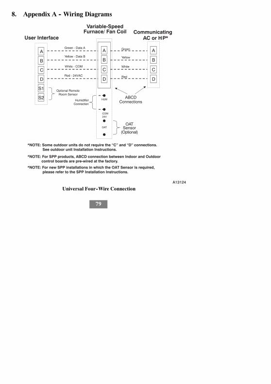
79
8. Appendix A -- Wiring Diagrams
A
B
C
D
A
B
C
D
User Interface
Green - Data A
Yellow - Data B
White - COM
Red - 24VAC
OAT
Optional RemoteRoom Sensor
HUM
COM24V
HumidifierConnection
S2
S1
A
B
C
D
ABCDConnections
Communicating AC or HP*
Green
Yellow
White
Red
OATSensor
(Optional)
Variable-SpeedFurnace/ Fan Coil
*NOTE: Some outdoor units do not require the “C” and “D” connections. See outdoor unit Installation Instructions.
*NOTE: For SPP products, ABCD connection between Indoor and Outdoor control boards are pre-wired at the factory.
*NOTE: For new SPP installations in which the OAT Sensor is required, please refer to the SPP Installation Instructions.
A13124
Universal Four--Wire Connection

80
A
B
C
D
A
B
C
D
C
Y
ABCDConnection
User Interface
1-Spd.Non-Communicating AC
Green - Data A
Yellow - Data B
White - COM
Red - 24VAC
Optional RemoteRoom Sensor
HUM
COM24V
HumidifierConnection
Y/Y2
S2
S1
OAT OATSensor
Variable-SpeedFurnace/Fan Coil
A12354
Connection Diagram for Furnace or FE Fan Coil with1--Stage Air Conditioning

81
A
B
C
D
A
B
C
D
ABCDConnection
User Interface
1-Spd.Non-communicating HP
Green - Data A
Yellow - Data B
White - COM
Red - 24VAC
Optional RemoteRoom Sensor
HUM
C
HumidifierConnection
Y
S2
S1
W2
Y
O
C
R
O
R
W
OAT OATSensor
Variable-SpeedFan Coil
G
A12355
Connection Diagram for FE Fan Coil with Non--communication1--Stage Heat Pump

82
A
B
C
D
Zone ControlUser Interface &Smart Sensor(s) Green
Yellow
White
Red
OAT
HUM
COM24V
HumidifierConnection
A
B
C
D
OATSensor
(Optional)
A B C D A B C D
DamperControlmodule
A B C D
IndoorUnit
CommunicatingAC or HP
A04018
Zoning Connection for Communicating Indoor Unit with2--Stage Communicating Outdoor Unit
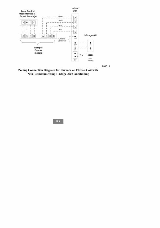
83
A
B
C
D
Zone ControlUser Interface &Smart Sensor(s) Green
Yellow
White
Red
OAT
HUM
COM24V
HumidifierConnection
OATSensor
A B C D A B C D
DamperControlmodule
A B C D
IndoorUnit
C
Y
1-Stage AC.
Y/Y2
A04019
Zoning Connection Diagram for Furnace or FE Fan Coil withNon--Communicating 1--Stage Air Conditioning

84
A
B
C
D
Zone ControlUser Interface &Smart Sensor(s) Green
Yellow
White
Red
A B C D A B C D
DamperControlmodule
A B C D
Variable-SpeedFan Coil
1-Spd. HPHUM
C
Y
W2
Y
O
C
R
O
R
W
OATOAT
Sensor
HumidifierConnection
G
A07149
Zoning Connection diagram for FE Fan Coil withNon--communicating 1--Stage Heat Pump

85
R
G
FE Fan Coil or
Variable Speed Furnace
A07114
G Input Wiring for Blower Operation

86
R
G
FE Fan Coil or
Variable Speed Furnace
A07115
G Input Wiring for System Shutdown

87
NOTES

88
NOTES (Cont.)


Infinity and HYBRIDHEAT are trademarks or registered trademarks of CarrierCorporation in the United States and other countries. Other brands and productnames are trademarks of their respective holders.
U.S. Export Classification: EAR99.Copyright 2014 Carrier Corp. S 7310 W. Morris St. S Indianapolis, IN 46231Edition Date: 02/14 997-011280-8-R
Manufacturer reserves the right to change, at any time, specificationsand designs without notice and without obligations. Replaces: SYSTXCCITW---07SI
Catalog No: SYSTXCCITW---08SI