
Systems Reference Library IBM System/360 Basic Programming Support Basic Assembler ... ·...
68
Systems Reference Library File No. S360-21 Form C28-6503-3 IBM System/360 Basic Programming Support Basic Assembler Language This publication contains information required for writing programs in the Basic Assembler language, a symbolic programming language for the IBM System/360. The Basic Assembler language provides programmers with a convenient way to make full use of the operating capabilities of the. IBM System/360. Source programs written in the Basic Assembler language are translated into object programs by a program called the Basic Assembler. The Basic Assembler and its language are both described in this The description of the language includes the rules for writing source programs, a list of the machine instructions that can be represented symbolically, and explanations of the instructions used to control the Basic Assembler. The description of the Basic Assembler consists primarily of dis- cussions of those features that affect the planning and writing of source programs.
Transcript of Systems Reference Library IBM System/360 Basic Programming Support Basic Assembler ... ·...

Systems Reference Library
File No. S360-21 Form C28-6503-3
IBM System/360 Basic Programming Support
Basic Assembler Language
This publication contains information required for writing programs in the Basic Assembler language, a symbolic programming language for the IBM System/360. The Basic Assembler language provides programmers with a convenient way to make full use of the operating capabilities of the. IBM System/360. Source programs written in the Basic Assembler language are translated into object programs by a program called the Basic Assembler.
The Basic Assembler and its language are both described in this public~tion. The description of the language includes the rules for writing source programs, a list of the machine instructions that can be represented symbolically, and explanations of the instructions used to control the Basic Assembler. The description of the Basic Assembler consists primarily of discussions of those features that affect the planning and writing of source programs.

PREFACE
This publication describes a symbolic programming language for the IBM System/360. All the information required for writing IBM System/360 programs is provided. This includes the rules for writing source statements, a description of the assembler Rinstructions,· and a list of the machine instructions that can be represented in the language. There is also a section describing the Basic Assembler, the program that translates source programs into machine-language programs. The information in this section will be helpful in planning for the IBM System/360 and in writing programs to permit the most efficient operation of the Basic Ass~mbler. This section describes the input to the Basic Assembler, the type of output that will be generated, and those operations of the Basic Assembler that have direct programming significance.
Completion of a basic course in computer systems and programming concepts, or the equivalent, is a prerequisite to using this publication. Readers should also be familiar with the IBM System/360 and have an understanding of the storage-addressing scheme, data formats, and machine instruction formats and functions. This information can be found in the publication IBM System/360 Principles of Operation, Form A22-6821.
Reference is made in this manual to the relocating loader and the absolute loader. A detailed description of th~_se programs is contained in the publication IBM System/360 Basic Programming Support Basic Utilities, Form C28-6S0S.
MAJOR REVISION (February 1965)
This publication is a major revision of the previous edition, Form C28-6503-2, which is now obsolete. Significant changes have been made throughout this publication; and the present edition should be reviewed in its entirety.
This publication was prepared for production using an IBM computer to update the text and to control the page and line format. Page impressions for photo-offset printing were obtained from an IBM 1403 Printer using a special print chain.
Copies of this and. other IBM publications can be obtained through IBM Branch Offices.
A form for readers' comments appears at the back of this publication. It may be mailed directly to IBM. Address any additional comments concerning this publication to the IBM Corporation, Programming Systems Publications, Department D58, PO Box 390. Poughkeepsie, N. Y. 12602
© 1964 by International Business Machines Corporation

INTRODUCTION • • • • • • • • • • Features of the IBM System/360 Basic
Assembler • • • • Compatibility with Other System/360
Assemblers • • • • • • Machine Requirements • • Card and Tape Options ••••
BASIC ASSEMBLER CARD FORMATS Statement Fields • • • • • • •
Name Field Operation Field • Operand Field • • Comments Field
Identification-Sequence Field
WRITING BASIC ASSEMBLER STATEMENTS Character Set Symbols •••••••••••
Defining .Symbols ••••• Previously Defined Symbols External and Entry-Point Symbols General Restrictions on Symbols •
The Location Counter • • • • • Self-Defining Values • • • • •
Decimal • • Hexadecimal • Character •
Expressions ••••• Relative Addressing • Attributes of Expressions • Absolute and Relocatable Expressions
Restrictions • • • • • • • • • •
MACHINE INSTRUCTION STATEMENTS Instruction format • • Implied Base Registers and Displacements • • • • • •
Implied and Explicit Lengths • Machine Instruction Mnemonics Machine Instruction Examples •
ASSEMBLER INSTRUCTIONS ••••• Assembler Control Instructions •
ICTL - Input Control START - Start Program • • • ORG - Reset Location Counter CNOP - Conditional No Operation • END - End Program • • • EJECT - Start New Page SPACE - Space Listing • • •
Definition Instructions EQU - Equate Symbol • • DS - Define Storage • CCW - Define Channel Command Word DC - Define Constant Character Constants (C) Hexadecimal Constants (X) • • • • Full-Word Constants (F) • • • • •
5
5
6 6 6
7 7 9 9 9
10 10
11 11 11 11 12 12 12 12 13 13 13 13 14 14 14
15 15
17 17
17 19 20 24
25 25 25 25 26 27 27 28 28 29 29 29 30 31 32 33 33
CONTENTS
Half-Word Constants (~ • • • • • Short-Precision Floating-point
Constants (E) ••••••• Long-Precision Floating-Point Constants (D) ••••••
Expression Constants (A) •••• Base Register Instructions • • • • •
USING - Use Base Address Register DROP - Drop Register • • • • • • Programming with the USING and
DROP Instructions • • • • • Loading Registers • • • • • •
Branch and Link (BALR or BAL) Instruction • • • • • • • •
Load Full-Word (L) Instruction Base Register Zero • • • • •
Program Linking Instructions • • • • ENTRY - Identify Entry-Point
Symbol • • • • • • • • • • • • • EXTRN - Identify External Symbol
Li.nking Conventions •••••••• Limitations on Program Linking Program Relocation and Linking
Assembler Instruction Summary
THE BASIC ASSEMBLER PROGRAM • Assembler Processing •
Phase 1 • • • • Phase 2 • • • • •
Program Listing Error Notification • Object Program Output • • • •
External Symbol Dictionary Card • • • • • • • • • • •
Text (TXT) Card • • • • • • Relocation List Dictionary
Card • • • • • • • • • Load End Card •
Patching Object Programs • Reassembly Procedure • • Symbol Table • • • • • • •
Symbol Table Overflow •
APPENDIX A. CHARACTER CODES
(ESP)
(RLD)
APPENDIX B. HEXADECIMAL-TO-DECIMAL CONVERSION • • • • • • • • • • •
APPENDIX C. PROGRAMMING EXAMPLE •
APPENDIX D. SYSTEM/360 ASSEMBLERS-LANGUAGE FEATURES COMPARISON CHART • • •
APPENDIX E. HEXADECIMAL TO MNEMONIC OPERATION CODE TABLE •
INDEX • • • • •
34
34
35 35 36 36 36
37 37
37 38 38 38
39 39 39 40 40
41
43 43 43 43 44 44 45
45 45
45 45 46 46 46 46
48
53
58
59
62
63

FIGURES
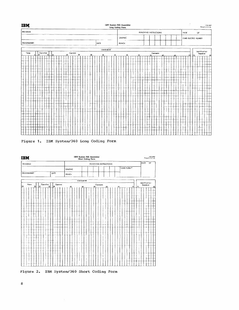
Figure 1 • IBM System/360 Long Coding Figure 11. Operand Field Summary · 19 Form . . . . · · · · · 8 Figure 12. Implied Operand Field
Figure 2. IBM System/360 Short Coding Summary . . . · · · · · 20 Form . . . · · · · · · 8 Figure 13. Boundary Alignment with a
Figure 3. Example of the Name Field 9 CNOP Instruction · · · . · · 28 Figure 4. Example of the Operation Figure 14. Channel Command Word · · 31
Field · · · 9 Figure 15. DC Statement Summary · · 33 Figure 5. Example of No Operand Field Figure 16. Example of Coding with USING
with Comments · · · · · · 9 and DROP Instructions 37 Figure 6. Example of the Operand Field 10 Figure 17. Example of Coding Using Base Figure 7. Example of the Comments Register Zero · · · · . · · 38
Field · · · · · · · 10 Figure 18. Example of Program Linking · 41 Figure 8. Example of Coding with Figure 19. Assembler Instruction
Previously Defined Symbols 12 Summary . . . · · · · · 42 Figure 9. Example of Relative Figure 20. Phase 2 Input for Use with
Addressing . · · · · · · 14 IBM 1442-2 Card Read-Punch · 44 Figure 10. Machine Instruction State-
ment Formats · · · · · · 18
The Basic Assembler language is a symbolic programming language for use with the IBM System/360. This language provides programmers with a convenient means of writing machine instructions, designating registers and input/output devices, and specifying the format and addresses of storage areas, data, and constants. All the operational capabilities of the IBM System/360 can be expressed in Basic Assembler language programs.
The language features are designed to greatly simplify the writing of programs for the IBM System/360. By avoiding unnecessary complexity, the language features reduce program errors and, consequently, the time required to produce a program that is suitable for execution. They also make it easier to learn the language.
Source programs written in this language are translated into IBM System/360 machine language object programs by the Basic Assembler (that is, "the assembler"). In the process of translating programs, the assembler performs certain auxiliary functions. Some of these functions are automatically performed; others must be requested by special assembler instructions that the programmer writes in his source program.
The assembler is a two-phase program stored on cards. It has a special operating procedure for use with the IBM 1442 Card Read-Punch. When this procedure is used, the assembler punches information into the source-program deck during the first phase. Using this information in the second phase, the assembler produces an object program. For systems with tape or a 1402-2 Card Read-Punch, this intermediate information is stored in a tape or card file rather than in the source-program deck. The temporary file then serves as input for the second phase.
FEATURES OF THE IBM SYSTEM/360 BASIC ASSEMBLER
The most significant features provided by the assembler and its language are summarized below. This summary does not include all the features nor does it contain complete explanations of the features listed. For more detailed descriptions, the reader is referred to subsequent sections.
INTRODUCTION
Mnemonic Operation Codes: Mnemonic operation codes are provided for all machine instructions. These codes are used instead of the more cumbersome internal operation codes of the machine. For example, the Branch-on-Condition instruction can be represented by the mnemonic BC instead of the machine operation code, 01000111. The various machine mnemonic operation codes are presented under the topic "Machine Instruction Mnemonics."
Symbolic Referencing of Storage Addresses: Instructions, data area, register numbers, and other program elements can be referred to by symbolic names, instead of actual machine addresses and designations. See the topic "Symbols. II
Automatic Storage Assignment: The assembler assigns consecutive addresses to program elements as it encounters them. After processing each element, the assembler increments a counter by the number of bytes assigned to that element. This counter indicates the storage location available to the next element. See the topic nLocation Counter. II
Convenient Data Representation: Constants can be specified as decimal digits, alphabetic characters, hexadecimal digits, and storage addresses. Conversion of the data into the appropriate machine format of the IBM System/360 is performed by the assembler. Data can be in a form suitable for use in fixed-point and floating-point arithmetic operations. See the topic "DC -Define Constant. R
Renaming Symbols: A symbolic name can be equated to another symbol so that both refer to the same storage location, general register, etc. This makes it possible for the same program item to be referred to by different names in different parts of the program. See the topic IIEQU Equate Symbol. n
Program Linking: Independently assembled programs that will be loaded and executed together may make symbolic references to instructions and data in one another. See the discussion of "program Link Instructions."
Relocatable Programs: The assembler produces object programs in a relocatable format; that is, a format that enables programs to be loaded and executed at storage locations different from those assigned when the programs were assembled.
Introduction 5
Assembler Instructions: A set of special instructions to the assembler is included in the language. Some of the features described in this section are implemented by these instructions. See the topic "Assembler Instructions."
Base Register and Displacement Assiqnment: The programmer can instruct the assembler to assign base registers and to compute displacements for symbolic machine addresses. See the discussion of -Base Register Instructions."
Program Listings: For every assembly, the assembler can provide a listing of both the source program and the resulting object program. A description of the listing format can be found under the topic "Program Listing."
Error Checking: Source programs are examined by the assembler for possible errors arising from incorrect usage of the language. Wherever an error is detected, a coded warning message (called a flag) will be printed in the program listing. For card systems without printers, limited error notification is provided. See the topic "Error Notification."
Program Reassembly: A special reassembly procedure is provided for programs assembled by the IBM 1442-2 Card Read-punch card-operating procedure. This will permit partially or completely assembled source programs, that have been modified, to be reassembled in less time than required for a new assembly. See the topic "Reassembly Procedure."
COMPATIBILITY WITH OTHER SYSTEM/360 ASSEMBLERS
Programs written in the Basic Assembler Language as described in this publication are acceptable to the other Basic Programming Support, Basic Operating System, and Operating System Assemblers, and the 7090/7094 Support Package Assembler. Similarly, source programs written in these other assembly languages are acceptable to the Basic Assembler if they do not embody any of the features of these assemblers which are unacceptable to the Basic Assembler. Appendix D contains a list of features supported by the System/360 Assemblers and may be used as a guide for the interchangeability of source programs.
The Basic Assembler will also accept programs written for the IBM System/360 Model 20 Basic Assembler, except where differences in machine design have made it necessary to include some instructions in
6
the Model 20 Basic Assembler Language that are not contained in the Basic Assembler Language. These instructions are:
BAS BASR CIO HPR SPSW TIOB XIO y-type Expression Constants
Note also that the pseudo-registe.rs zero through three on the Model 20 are handled differently from the corresponding actual registers on other models of the System/360.
MACHINE REQUIREMENTS
The assembler will operate on an IBM System/360 with the following minimum configuration:
8,192 bytes of storage Standard Instruction Set One IBM 1442 Model 2 or 1402 Card
Read-Punch
The above configuration is for the cardoperating procedure for the assembler, hereinafter called the card option.
If, in addition to required for the card 2400-Series Magnetic Tape available, the tape-operating be used. This procedure will termed the tape option.
the equipment option" IBM
Units are procedure may be henceforth
If an IBM 1443 Model 2 or 1403 Printer, or an IBM 1052 Printer-Keyboard is provided, the assembler will provide a program listing, complete with error messages, for each assembly. An option is available to list only those statements containing errors. For information concerning this option, refer to th(~ topic nprogram Listing."
CARD AND TAPE OPTIONS
The Basic Assembler is a two-phase program. The first phase produces data for use by the second phase. The intermediate data produced by phase 1 must be passed on to the second phase via some external storage medium. The storage mediums used are punched cards or magnetic tape. If punched cards are used for the intermediate data, the system is known as a "Card Option System." If tape is used, the system is termed a nTape Option System. 1I The machine configuration determines which option applies at a particular installationo

An assembler language source program consists of a sequence of source statements punched into cards, one statement per card. The card columns available for punching source statements vary with the machine configuration (that is, input device, card or tape option) and the programmer's discretion. See the following list.
InEut Unit °Etion Columns Available
1402 tape 1-71 or 25-71 1402 card 1-47 (see note) or 25-71 1442 tape 1-71 or 25-71 1442 card 25-71
Note: Columns 1-71 may be used for the 1402 card option rather than only columns 1-47. The assembler scans all 71 columns of the statement field when obtaining the information required to generate the appropriate object codej however, only the contents of columns 1-47 are included in the program listing produced by the assembler.
In addition to a source statement, each card may contain an identification sequence number in columns 73-80.
In this section, the discussion of card formats assumes that all statements begin in column 1. When card column assignments differ because of statements beginning in column 25, the column numbers associated with the statements beginning in column 25 are placed in parentheses. Example: 1 (25) •
The statements may be written on the standard coding forms that IBM provides. Two forms are available: a "long" f.orm, Form X28-6507 ~igure 1), and a "short" form, Form X28-6506, for IBM Card ReadPunch card-option assemblies (Figure 2) •
Each line of the coding form is used to write a single statement and/or comments. The information on each line is punched into one card. If a card is completely
BASIC ASSEMBLER CARD FORMATS
blank, it will be ignored by the assembler. The position numbers shown in the forms correspond to the card columns.
Space is provided at the top of both coding forms to identify the program and give instructions to the keypunch operator. None of this information is punched into the statement cards.
STATEMENT FIELDS
An assembler statement is composed of one to four fields, from left to right: name field, operation field, operand field, and comments field. The identification-sequence field is not part of the statement. The statement fields can be written on the coding form in what basically is a free form. As a convenience, however, the name and operation fields are marked on the coding forms by heavy lines that indicate the maximum length of these fields. Programmers may wish to align the fields at these lines to create a neat and orderly appearance in the program listing.
Some general rules that must be observed when writing statements are:
1. The only required field in a statement is the operation field. The other fields are optional, depending on the operation and the programmer's wishes.
2. The fields in a statement must be in order and separated from one another by at least one blank.
3. The name, operation, and operand fields must not contain embedded blanks. A blank may, however, occur in the operand field as a character self-defining value or character constant.
4. Only one statement is allowed to a linej a statement cannot be continued on additional lines.
5. Column 72 must be blank.
Basic Assembler Card Formats 7
IB'4 IBM SYBtem/360 Assembler Long Coding Porm
PROGRAM C--._
PROGRAMMER
Name Operation Operand
1-'-r-..-,.-r4-+,,8.,.,.-r,1!.!.2H~14T-'r-r-..-'-' ?9,._ _._ 25 1_ ~-...jl-+-+-f--·-I--f·· -I--f--
+-+--,-f--f-f--+-+ + -1- f-· f .. - c'- f---. -
--.- - f - I-
f
f---f--
- f-·f····· ~-.- ·-·I-f-I·-- -+- -f-· f--I- - c--- ---f- 1---
1----1-.. ----1----- --·f··-I-I---I--I '- 1--
1-+-1· .-+ 1·--1-+--1---+-+- -1-1-- f c- -f-. - 1--- -+- - --f--
-++-.--1-+-++-1--1---+- '--1--1- 1-.. -- -+ -I--f-+ ++-'1-1- f--I---f· ---I-- - / - 1--
-+--+-1f--+++ .+-1'-+--1----1-+-1---1.-1- -1··1 1-- -.- - t-1- --I- .--f--
----·1-·- I· I f---1-1-- . ----1--1--.. - f- -/- 1--1- f-f----·- I·/-t
I
30
f·
f-
STATEMENT
35
-I"
- -1--1--1--'
f
I·
40
/ II c-
/. -++-
GRAPHIC
PUNCH
45
I--I-j·
PUNCHING INSTRUCTIONS PAGE OF
50
I I
I I T r 1~_1 T
Comments
I T I 1
CARD ELECTRO NUMBER
-"--
IdentificationSequence
55 65 71 73 80
f---I-- .. --~-1---l--+---+-I--I----I-. ,-.- I-f- 1- -f-I--1-- -+
f-I--- f- ~- .-1-1--•. - --1-.-+---+---+-----1---+---+-1
1-- -- - - f- --- - 1-- 1- f+-- -j-I-- - --- .. -. I -f-I--
I-I
.-./-I- - f-+-·
- -+-+-1--1--
+-II++-I--+-\-I---j- -+.+-I----+-+-I----l--I-+-l--\---j
1+-++ -tt·-I--- - - f-- -- I- 1--1----1--1--1-+-+-+-I· --1-+-1-
f--- - .. -1-+-1--
--I- 1- 1-- f---I--
- +.1-1-- - 1-1-- - 1-- ---1--1-
/.- 1--+ +·t-l-- f· -tt I-·t· +--+-t-I-I -1-- f-- 1---1- -j---+-+ 1- 1-- 1- I- - 1--1-- -f····/- - f -+--f-I-I-I-+-+-II+ 1 1 I- 1--1-+-\. f--I-f
f--·- - i-\-·
f ·-I--i-I-1- 1-- I- - - - - f-· f· - 1- 1-' + +····1·· -f- +-- f---I-I-- -.--\--+--1----11-+---1---1- -1---1---1- -I- 1---I-+++-~'--++-
I
-l
I-
1-+-I-
1--1-
f-- -
I -1---
+-- .1-1-'--,- -
1---1·-1-
- - f-f f·-I--I-- - 1-- - f---· ·-f--I-
1-- - 1-- f- t-~-+--I-'f--+ -t- +.-. +--1
1+- .- - I- -t+-I-I-' .. 1--1--- -
1
I I---
If- -If-I -++- -1-1-
-I-- -
'1-1-' 1-
I-f---
I·· -1-- f··-f-·- -. 1-- - -- f 1- 1-
- 1--1-- -1-
- -+- 1--1--1-
i-
1- 1- -1--1--I---f- -f-f-··f·-
1-1- I-- - -+ +--1-1-+·1 1----
-1-
1---
1- I-
-1---1-1-
1--- . - - 1--.1- --1-+-1 -1- I· -. .; +--I-f -\-.-+ -1-1- f-· t- -I-~-I·__l-··· ~ .. I-----I-i - - 1-1---f--f-- . ..f.-I-
-,.-1----- -.1-.- .1- 1-1--
-- ·-1-1-- -- --I-- - f-
1- 1- - 1-+'- 1- - 1-1----
1---1-1- - 1---!--I-I-I-- - -+-f-+-+-~+ - f 1--1--- f- 1----
Figure 1. IBM Systern/360 Long Coding Form
IBJt1 PROGRAM
GRAPHIC
LP_RO __ G_R_A_M_M_ER ________ ~E _____ _L __ _ ~ PUNCH
IBM SyetBmi360 ASB9mbler Short Codinll Porm
PUNCHING INSTRUCTIONS
CARD FORM N
X28-6506 Prinled in U.S.A.
PAGE OF
---------------------------------------~ST~A~TE~M~E~NT~----------------------------.
Name Operati on Operand Comments 25 30 32 36 38 45 5~0 ... _r~-,~55T_, W
_ . __ ~_ c_
c····
1-
1-- - 1·1-· - 1--1 -
- i--I-- -I-f····
f- - f-- .- I- c---f····· -I
1·- -- I- - - f-
f- -t-·j··· f.-
1-1 +.--1-1---+-1-I--f
I I·
f
1-
1- 1-
i-
1- -
-
i
1-
-i f
i-i-- 1-
ff.--f
-- I- -1-1-- -- -
-1-1-- - f-f-
1-
1_
- 1- - - 11-++
-++-1-+ ++-1-+-+. 1- 1-
1- -
f- C"
- 1--+- -
I -1-+++ 1-·+-1-1-- - - I
I fl-- ·1·· ~.. . .... f····
1-
- .. I··· 1- i··I-
f···I···-···I·
~--
-+-I·-··j·-·· -f- 1-+- -1-- /-
-I-
c···· / ..
f
:-
Figure 2. IBM System/360 Short Coding Form
8
65
Identification-Sequence
71 73 80
1- -, ... -
-
1·- ,- - I-- ~-
- I-I--f--I' t-f-- t
I
-I--
- .....
-1-- c----1-
1-- +-1-" -f-I--
I·
I
.-
i--- 1--
...... 1---... 1--
f--/··· -
If-It-
I I -~~-4--~++ +4·1+ + 1 1/-
1-1-
t·-
/ .. _.-
1-~ .. 1. --I ... j. .. -j.----j~__+_I_ .. - I--
..
t
1-- -I--I-
f---I--I-
-- 1---1-1-1-
-1-1--·1--
f-___ '- _ ...... L.
f--
·1-··
/-
1
I- -
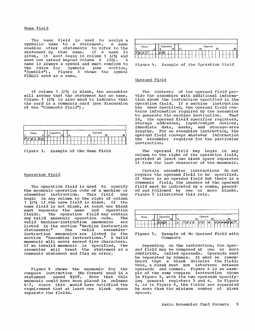
The name field is used to assign a symbolic name to a statement. A name enables other statements to refer to the statement by that name. If a name is given, it must begin in column (25) and must not extend beyond column 6 (30). A name is always a symbol and must conform to the rules for symbols (see section, "Symbols") • Figure 3 shows the symbol FIELD2 used as a name.
If column 1 (25) is blank, the assembler will assume that the statement has no name. Column 1 (25) is also used to indicate that the card is a comments card (see discussion of the "Comments Field") •
Figure 3. Example of the Name Field
Operation Field
The operation field is used to specify the mnemonic operation code of a machine or assembler instruction. This field may begin in any column to the right of column 1 (25) if .the name field is blank. If the name field is not blank, at least one blank must separate the name and operation fields. The operation field may contain any valid mnemonic operation code. The valid machine-instruction mnemonics are listed in the section "Machine Instruction Statements;" the valid assemblerinstruction mnemonics are listed in the section "Assembler Instructions. n A valid mnemonic will never exceed five characters. If an invalid mnemonic is specified, the assembler will treat the statement as a comments statement and flag an error.
Figure 4 shows the mnemonic for the compare instruction (RR format) used in a statement named TEST. . Note that this mnemonic could have been placed in columns 6-7, since this would have satisfied the requirement that at least one blank space separate the fields.
Name Operand
Figure 4. Example of the Operation Field
Operand Field
The contents of the operand field provide the assembler with additional information about the instruction specified in the operation field. If a machine instruction has been specified, the operand field contains information required by the assembler to generate the machine instruction. That is, the operand field specifies registers, storage addresses, input/output devices, immediate data, masks, and storage-area lengths. For an assembler instruction, the operand field conveys whatever information the assembler requires for the particular instruction.
The operand field may begin in any column to the right of the operation field, provided at least one blank space separates it from the last character of the mnemonic.
Certain assembler instructions do not require the operand field to be specified. If there is no operand field but there is a comments field, the absence of the operand field must be indicated by a comma, preceded and followed by one or more blanks. Figure 5 illustrates this rule.
Name Operand
Figure 5. Example of No Operand Field with Comments
Depending on the instruction, the operand field may be composed of one or more subfields, called operands. Operands must be separated by commas. It must be remembered that a blank delimits the field; thus, a blank must not intervene between operands and commas. Figure 6 is an example of the same compare instruction shown in Figure 4, with its two operands specifying general registers 5 and 6. In Figure 6, as in Figure 4, the fields are separated by more than the minimum number of blank spaces.
Basic Assembler Card Formats 9

Nome Operand
Figure 6. Example of the Operand Field
Comments Field
Comments are strictly for the convenience of the programmer. They permit lines or paragraphs of descriptive information about the program to be inserted into the program listing. Comments appear only in the program listing; they have no effect on the assembled object program. Any valid characters (including blanks) may be used as comments.
The comments field must (1) appear to the right of the operand field and (2) be preceded by at least one blank. If there is no operand field but there is a comments
field, the absence of the operand field must be indicated by a comma, preceded and followed by one or more blanks. The entire statement field can be used for comments by placing an asterisk in column 1 (25); the entire statement will be treated as comments. Column 72, however, must remain blank.
If it is necessary to continue full-card comments on additional lines, each such line must have an asterisk in column 1 (25), as illustrated in Figure 7.
IDENTIFICATION-SEQUENCE FIELD
The identification-sequence field may be used for program identification and statement sequence numbers. This field can occupy columns 73-80 only. The information in this field normally is punched in every statement card. The assembler, however, will not check this field. It will merely reproduce the information in the fiE~ld on the output listing of the program.
STATEMENT (
1 Name 6 SOperatian12
14 20 Operand 25 30 35 40 45 50 55 Comments (
*AN ASTER1Sl< IS RE~l!!~E'D Itt EA~IH~lltg()fC()""M.ENTS· -----r------r--;> ... THE A 5 T £ R 1 SKI N ~ ~ ~ ~ " "00 /l! A K E S 1"1£)[ .su __ ~ _ COM NI E N T S ~ I N~· ___ , ,
TEST C~ _~~l_I~~~~~QM~~~~~:~9 ~~T~Ng~~~AN AST~Rl~~--~~
Figure 7. Example of the Comments Field
10

Language statements will be accepted by the assembler only if they conform to the established grammatical rules and vocabulary restrictions that are presented in this section. The reader can expect that many of the points not fully explained when they are first mentioned in this section will be described in detail subsequently.
CHARACTER SET
Basically, statements may be written using the following characters:
A through Z o through 9 * + - , () blank
The card column punch-combinations that the assembler will accept for these characters are listed below. This list also contains the punches assumed for additional printer graphics, which may be used in comments.
r------------T----------------------------, I Character I Punch Combination I ~------------+----------------------------~ A - I 12 punch and a 1 - 9 punch,
J - R
S - Z
o - 9 blank , /
(period) $ , 4/: < * ~ Q)
( ) • (single
quotation) +
respectively 11 punch and a 1 - 9 punch,
respectively o
o No 12 0-1
(z ero) punch and a 2 - 9 punch, respectively (zero) - 9, respectively
punches
11 12-3-8 11-3-8 0-3-8 3-8 12-4-8 11-4- 8 0-4-8 4-8 12-5-8 11-5-8 5-8
12-6-8 1= 6-8 L ____________ ~ ___________________________ _
WRITING BASIC ASSEMBLER STATEMENTS
SYMBOLS
Symbols are created by the programmer and used by him for symbolic referencing of storage areas, instructions, input/output units, and registers.
A symbol may contain from one to six characters; the characters may be any combination of alphabetic (A through Z) and numerical (O through 9) characters. The first character must be alphabetic. Special characters and embedded blanks must not be used in symbols. Any violation of these rules will be noted with an error flag in the program listing and the symbol will not be used.
The following are valid symbols:
READER A23456 LOOP2 N S4
These symbols are invalid:
256B
AREATWO RCD*34
First character is not alphabetic More than six characters Contains a special character
Defining Symbols
Symbols are meaningful in statements when used as operands and names. When a symbol is used as an operand, the assembler will normally assign certain attributes to it. These "attributes" are assigned to the symbol by the assembler when the symbol is defined. In order for a symbol to be used as an operand, it must be defined somewhere in the program.
A symbol is defined when the programmer uses it as the name of a statement. When the assembler finds a symbol in the name field, it will assign an address-value attribute and a length attribute to the symbol. The address value is the storage address of the leftmost byte of the field allo·tted to the statement; the length is the number of bytes in the storage field named by the symbol. This length is called the implied length associated with the symbol. The convenience of having implied
Writing Basic Assembler Statements 11

lengths will become apparent in the discussion of the symbolic format of machine instructions in the SS format.
A symbol defined in this manner is normally called a relocatable symbol. That is, the address value of the symbol will change if the program is loaded at a location other than its assembled location.
Symbols can be assigned arbitrary absolute values by use of the EQU assembler instruction. These values may designate registers, input/output units, immediate data, etc. They can also specify actual storage addresses such as permanently allocated interrupt locations. Symbols so defined are termed absolute symbols since their values are fixed and will not change because of program location.
Previously Defined Symbols
Sometimes the programmer will desire to give an alternate name to a previously defined symbol. "Previously defined" means that the symbol has appeared as the name of some statement prior to being used in the operand field of another statement. Figure 8 shows how the symbol TEST, defined in the first statement, is given an alternate name.
Name Operation Operand 1 6 8 12 14 20 25 30
TE ST CR ~,' ml TLi~ +- ~~ I
La OP EQV ~--
_~ - c-..... _ c ___
Figure 8. Example of Coding with Previously Defined Symbols
External and Entry-Point Symbols
Symbols are normally defined in the same program in which they are used as operands. It is possible, however, to define a symbol in one program, use it in another program assembled independently of the first, and then execute both programs together. Such a symbol is called an "external symbol" when it is used as an operand. The symbol is termed an "entry-point symbol" in the program in which it is defined. The address value of the entry-point symbol will be assigned to the external symbol when both programs are loaded by the relocating loader.
12
Before using an external symbol or defining an entry-point symbol, the programmer must indicate to the assembler which of the symbols are external and which are entry points. The ENTRY and EXTRN assembler instructions are provided for this purpose. Both instructions are described in the section nAssembler Instructions."
External symbols are always relocatable. They are subject ~o certain usage restrictions that are discussed at pertinent places elsewhere in this publication.
General Restrictions on Symbols
The following restrictions are in addition to those imposed elsewhere in the discussion of symbols:
1. A symbol may appear only once in a program as the name of a statement. If a symbol is used as a name more than once, only the first usage will be recognized. Each subsequent usage of the symbol as a name will be ignored and noted with an error flag in the program listing.
2. The number of symbolS that may be defined in a program is restricted, depending on the machine's storage size. These restrictions are explained in detail in the section "The Symbol Table."
3. A symbol must always be defined as having a positive value not exceeding 65,535. Any symbol whose definition is contrary to this rule will not be used and the statement in which it appears will be flagged as an error.
THE LOCATION COUNTER
The assembler maintains a counter that it uses to assign consecutive storage addresses to program statements. This counter is called the Location Count.er. It always points to the current address. After each machine instruction is processed, the Location Counter is incremented by the number of bytes assigned to that instruction. Certain assembler instructions also cause the Location Counter to be incremented, whereas others do not affect it.
The programmer can set and change the Location Counter by using the START and ORG assembler instructions described in the section "Assembler Instructions."

Location Counter Overflow: The maximum value of the Location Counter is 65,535, a 16-bit value. If a program being assembled causes the Location Counter to be incremented beyond 65,535, the assembler will retain only the rightmost 16 bits in the counter and continue the assembly, checking for any other source program errors. No object program will be produced. The assembler can, however, provide a listing of the entire source program. The statement causing the overflow will be flagged in the listing.
Proqrarn References: The programmer may refer to the current value of the Location Counter at any place in a program by using an asterisk as an operand. The asterisk represents the location of the first byte currently available. The use of an asterisk in a machine-instruction statement is the same as giving the statement a name and then using that name as an operand in the same statement. Note that the asterisk will have a different address value each time it is used. The asterisk will have the same length attribute that a symbol placed in the name field would have. An asterisk used as an operand is considered a relocatable symbol.
SELF-DEFINING VALUES
The ability to represent an absolute value symbolically is an advantage in cases where the value will be referred to repeatedly. However, it is equally necessary to have a convenient means of specifying an actual machine value or a bit configuration without having to go through the procedure of equating it to a symbol and using the symbol. The assembler language provides this facility through the self-defining value, which can be a decimal, hexadecimal, or character representation.
Self-defining values may be used to specify such program elements as immediate data, masks, registers, addresses, and address increments. The type of representation selected (decimal, hexadecimal, or character) will depend 'on what is being specified. The use of a self-defining value is quite distinct from the use of data constants specified by the DC assembler instruction and by literal operands. When a self-defining value is used in a machine-instruction statement, its value is assembled into the instruction. When a data constant is specified in a machine instruction, its address is assembled into the instruction.
Decimal
A decimal self-defining value is an unsigned number of from one to six decimal digits. A decimal self-defining value of more than six digits is not valid. The acceptable decimal digits are 0 through 9. Some examples are:
7 147
4092 128
0007 199860
The assembler imposes additional restrictions on decimal self-defining values, depending on their use. For example, a decimal self-defining value designating a general register should be from 0 through 15; one designating a core storage address should not exceed the size of available storage.
Hexadecimal
A hexadecimal self-defining value is an unsigned number of from one to six hexadecimal digits, enclosed in single quotation marks and preceded by the letter X. Hexadecimal self-defining values of more than six digits are not valid.
Each hexadecimal digit converts to a four-bit value. The hexadecimal digits, and their bit patterns are:
0 0000 4 0100 8 1000 C 1100 1 0001 5 0101 9 1001 D 1101 2 0010 6 0110 A 1010 E 1110 3 0011 7 0111 B 1011 F 1111
The following are examples of hexadecimal self-defining values:
X' 25' X'F4F'
X'B' X, OOCD'
X'12FA1E' X'OOEO'
A table for converting decimal to hexadecimal is provided in Appendix B.
Character
A character self-defining value is a single character, enclosed in single quotation marks and preceded by the letter C. A character self-defining value may be a blank or any combination of punches in a single card column that translates into the 8-bit IBM Extended BCD Interchange Code. There are 256 such combinations. Appendix A is a table of these combinations, their interchange codes, and, where applicable, their printer graphics. A single quotation
Writing Basic Assembler Statements 13
mark used as a character self-defining value, or an ampersand, is represented as two single quotation marks, or two ampersands, enclosed in single quotation marks, thus: C···· or C'&&'
Examples of values are:
C'/' C'B'
character
C'#' C'2'
self-defining
C'. • C' • (blank)
The same value can frequently be represented by anyone of the three types of self-defining values. Thus, the decimal self-defining value 196 can be expressed in hexadecimal as X'C4' and as a character, C·D·. The selection of a particular type of value is lef·t to the programmer. Decimal self-defining values, for example, might be used for actual addresses or register and input/output unit numbers; hexadecimal self-defining values for masks; and character self-defining values for immediate data.
EXPRESSIONS
The term Rexpression" refers to symbols or self-defining values used as operands, either singly or in some arithmetic combination. Expressions are used to specify the various fields of machine instructions. They also are used as the operands of assembler instruction statements.
Expressions are classified as either simple or compound and either relocatable or absolute. Unless otherwise qualified, the term Rexpression H as used hereinafter implies any expression, simple or compound, absolute or relocatable.
A simple expression is a single unsigned symbol (including the asterisk used as the Location Counter value) or a single unsigned self-defining value used as an operand. The following are simple expressions:
FIELD2 X'BF'
2
* C'R' ALPHA
A compound expression is a combination of two or, at most, three simple expressions, connected to each other by arithmetic operators. The recognized operators are + (plus), (minus), and * (asterisk), denoting, respectively, addition, subtraction, and multiplication. The following are compound expressions:
14
N+14*256 FIELD+X'2D'
ENTRY-OVER *+GAMMA-200
Note that an asterisk is used abov4~ both for the Location Counter (*+GAMMA-200) and as an operator (N+14*256), but cannot be used in succession to denote the two in the same expression. The following example is invalid:
A compound expression must not contain either two simple expressions or two operators in succession, nor may it begin with an operator. The following examples violate these rules and, therefore, are invalid:
AREAX'C' FIELD+-10
Relative Addressing
-DELTA+256 +FIELD-10
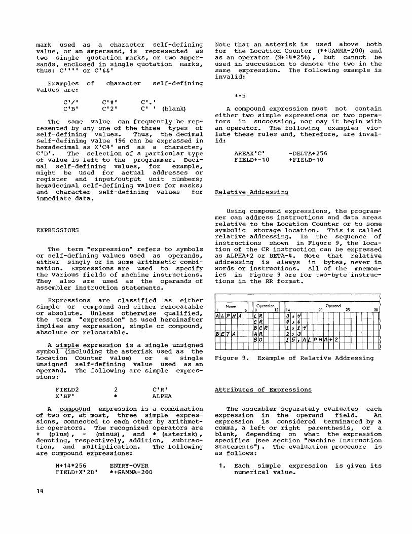
Using compound expressions, the programmer can address instructions and data areas relative to the Location Counter or to some symbolic storage location. This is called relative addressing. In the sequence of instructions shown in Figure 9, the location of the CR instruction can be expressed as ALPHA+2 or BETA-4. Note that relative addressing is always in bytes, never in words or instructions. All of the mnemonics in Figure 9 are for two-byte instructions in the RR format.
Name Operation Operand 1 6 8 12 14 20 25 30
AL PIIA LR J , J/ CR. " , 6 --
~- ~ 8 1. , 11 _.
BE _fA AR -f-- 2 J .:3 Be J 5 1 A LP HA +2 - '--I--
--'--
Figure 9. Example of Relative Addre·ssing
Attributes of Expressions
The assembler separately evaluates each expression in the operand field. An expression is considered terminated by a comma, a left or right parenthesis, or a blank, depending on what the expression specifies (see section "Machine Instruction Statements n
). The evaluation procedure is as follows:
1. Each simple expression is gi.ven its numerIcal value.
2. Moving from left to right, the arithmetic operations are performed, multiplication before addition and subtraction. Thus, A+B*C is evaluated as A+ (B*C) and not (A+B) *C.
3. The arithmetic result becomes the value attribute of the expression.
In addition to computing the value attribute of an expression, the assembler also determines its length attribute. For a compound expression, the length attribute is the same as the implied length attribute of its leftmost simple expression. If the leftmost simple expression in an expression is a self-defining value or an asterisk, the implied length attribute of that expression is one byte.
Absolute and Relocatable Expressions
An expression is absolute if it (1) contains only absolute symbols or selfdefining values, or (2) is of the following forms (where R is a relocatable symbol and A is an absolute symbol or self-defining value)
R-R R-A-R
R-R+A A-R+R
R-R-A R+A-R
A+R-R
Although the address values of both relocatahle symbols are subject to change when the program is loaded, the difference between their values will be constant; that is, absolute.
A relocatable expression is one whose value would change by N if the program was loaded N bytes away from its assembled location. Relocatable expressions must therefore conform to these rules:
1.
2'.
A relocatable expression must contain either one or three relocatable symbols. If there are three relocatable symbols, one (and only one) must be preceded by the minus (-) operator. If only one relocatable symbol is present, it must not be preceded by the minus operator. -A relocatable symbol may not be multiplied. That is, it must not be preceded or followed by the asterisk (*) operator.
The following examples illustrate absolute and relocatable expressions. R represents relocatable symbols; A, absolute symbols.
Absolute Expressions: R-R+5 A+14*C ' H' 2048 A*A
Relocatable Expressions: R+2 R-8*A R-R+R *-X ' FB2 1
R-A
The following expressions are for the reasons listed:
R+R R+R-A
R*A
R+R+R
Contain two relocatable symbols.
Relocatable symbol is multiplied.
No minus operator.
invalid
A-R Single relocatable symbol is preceded by a minus operator.
R-R-R Two minus operators.
Restrictions
The following restrictions apply to all expressions. Additional limitations are imposed where pertinent in this publication.
1. An expression can have a negative value only when it is an absolute expression specifying an address constant using the DC assembler instruction.
2. An expression containing an external symbol may not contain any other relocatable symbols. For the purpose of evaluating such an expression, the value of the external symbol at assembly time will be zero; the symbol will be revalued when the program is loaded.
3. If an expression is used as the operand of a machine instruction statement, any self-defining values within it must not exceed 4,095. Instructions containing self-defining values exceeding 4,095 will be set to zero. The operation code will remain unchanged.
4. The maximum value of an expression is 65,535. If an expression exceeding this maximum is used in a machine instruction statement, the entire instruction except for the operation code will be set to zero; if used in
Writing Basic Assembler Statements 15

instruction except for the code will be set to zero; an assembler instruction the action taken depends instruction.
operation if used in statement,
on the
Note: The maximum value of each individual term in the operand field of USING, ORG, END, EQU, CCW (second operand), and DC (A)
16
as~embler instructions must not exceed 16,777,215. The maximum value of an entire expression in an operand field of a USING, ORG, END, or EQU instruction is, however, 65,535. The maximum value of an entire expression in the operand field of a DC (A) or CCW (second operand) instructi.on is 16,777,215.

The assembler language provides for the symbolic representation of all machine instructions. The symbolic format of these instructions varies with the machine format. There are five basic machine formats: RR, RX, RS, SI, and SSe Within each basic format, further variations are possible.
Machine instructions are automatically aligned by the assembler on half-word boundaries. Any byte skipped because of alignment will be set to zero. Such situations arise when data is inserted into the instruction string, as in a calling sequence.
Any machine instruction statement may be given a name, which other language statements can use. The value attribute of such a name is the address of the leftmost byte assigned to the assembled instruction. The length attribute of the name depends on the basic machine format:
Basic Machine Format
RR RX RS SI SS
INSTRUCTION FORMAT
Implied Length (in Bytes)
2 4 4 4 6
Figure 10 shows each basic machine format, followed by its corresponding symbolic operand field formats and mnemonic operation codes. The numbers in the basic machine formats are the bit sizes of the field.
Figure 11 identifies the field codes used in Figure 10. Figure 11 also contains other pertinent information for specifying the fields in machine instruction statements. The following are additional points that must be considered:
1. If no indexing is used in an RX instruction and the base register (B2) is present, the X2 field must be written as a zero. If indexing is
MACHINE INSTRUCTION STATEMENTS
used, and if the base register is implied, the base register field may he omitted.
2. If the field or fields enclosed in parentheses are omitted, the parentheses (and the comma between them) may also be omitted.
3. If the value of an absolute expression exceeds the maximum (stated in Figure 11) for a field, the entire instruction will be set to zero except for the operation code; the statement will he flagged in the program listing. The preceding does not apply to the displacement field.
4. If the value of a displacement field exceeds 4,095, only the rightmost 12 bits will be used; the listing will be flagged.
5. If the programmer writes an absolute expression specifying a displacement and does not specify a base register, the assembler will place zero in the base-register field. The same applies to the index register.
6. If any invalidity in the operand field (other than those listed above) prevents correct evaluation of an expression, the entire instruction, except for the operation code, will be set to zero and the statement will be flagged. Such invalidities would include undefined symbols, use of relocatable expressions where absolute expressions are called for, etc.
IMPLI1~D BASE REGISTERS AND DISPLACEMENTS
The assembler has the facility for assigning base registers and computing displacements for symbolic storage addresses. If this facility is used, the programmer simply specifies a symbolic address, by using a relocatable symbol, thus implying that the assembler is to select the base register and displacement. Before this can be done, however, the programmer must indicate to the assembler the contents and number of the general regi~ters available for base registers. This information is conveyed with the USING and DROP instructions described in the section "Base Register Instructions."
Machine Instruction Statement 17

r-----------------------------------------------T---------------------T-----------------, I Basic Machine Format . I I I I----T-------T---T---T---T---------T---T--------I Assembler Operand I Applicable I I Bits I 8 I 4 I 4 I 4 I 12 I 4 I 12 I Field Format I Instructions I ~----+-------+---+---+---+---------+---+--------+---------------------+-----------------~
I I I I I I I I All RR instruc-Op CodelR1 IR2 IN/AI N/A IN/AI N/A I R1,R2 I tions except
I I I I I I I I BCR,SPM,SVC -------+---+---+---+---------+---+--------+---------------------+-----------------
I I I I I I I I Op CodelM1 IR2 IN/AI N/A IN/AI N/A I M1,R2 I BCR
I I I I I I I I RR -------+---+---+---+---------+---+--------+---------------------+-----------------
I I I I I I I I Op CodelR1 10 IN/AI N/A IN/AI N/A I R1 I SPM
I I I I I I I I -------+---~---+---+---------+---+--------+---------------------+-----------------
I I I I I I I Op Codel I IN/AI N/A IN/AI N/A I I I SVC
I I I I I I I ~----+-------+---T---+---+---------+---+--------+---------------------+-----------------~ I I I I I I I I I I I I lOp CodelR1 IX2 IB2 I D2 IN/AI N/A I R1,D2 (X2,B2) I All RX instruc- I I I I I I I I I I I tions except BC I I RX 1-------+---+---+---+---------+---+--------+---------------------+-----------------1 I I I I I I I I I I I I lOp CodelM1 IX2 IB2 I D2 IN/AI N/A I M1,D2(X2,B2) I BC I I I I I I I I I I I I ~----+-------+---+---+---+---------+---+--------+---------------------+-----------------~ I I I I I I I I I I I I lOp CodelR1 IR3 IB2 I D2 IN/AI N/A I R1,R3,D2 (B2) I BXH,BXLE,LM,STM I I I I I I I I I I I I I RS 1-------+---+---+---+---------+---+--------+---------------------+-----------------1 I I I I I I I I I I I I lOp Code I R 1 I R3 I B2 I D2 I N/A I N/A I R 1, D2 (B2) I All shift I I I I I I I I I I I instructions I ~----+-------+---~---+---+---------+---+--------+---------------------+-----------------~ I I I I I I I I I All SI instruc- I I lOp Code I 12 IB1 I D1 IN/AI N/A I D1 (B1) ,12 I tions except I I I I I I I I I I LPSW,SSM,HIO, I I SI I I I I I I I I SIO,TIO,TCH I I I-------+---T---+---+---------+---+--------+---------------------+-----------------1 I I I I I I I I I I I I lOp Code I 0 10 IB1 I D1 IN/AI N/A I D1 (B1) I LPSW,SSM,HIO, I I I I I I I I I I I SIO,TIO,TCH,TS I ~----+-------+---+---+---+---------+---+--------+---------------------+-----------------~ I I I I I I I I I I PACK,UNPK,MVO, I I lOp CodelL1 IL2 IB1 I D1 IB2 I D2 I D1 (L1 ,B1) ,D2 (L2,B2) I AP,CP,DP,MP,SP, I I I I I I I I I I I ZAP I ISS I-------+---~---+---+---------+---+--------+---------------------+-----------------1 I I I I I I I I I NC,OC,XC,CLC, I I lOp Codel L IB1 I D1 IB2 I D2 I D1 (L,B1) ,D2 (B2) I MVC,MVN,MVZ,TR, I I I I I I I I I I TRT, ED, EDMK I L ____ ~ _______ ~ _______ i ___ i _________ i ___ i ________ i _____________________ i _________________ J
Figure 10. Machine Instruction Statement Formats
Base registers and displacements can be implied for RX, RS, SI, and SS instructions. For example, the operands of an R~ instruction can be specified as
R1, R3, S2
where S2 represents a symbolic address (i.e., a relocatable symbol) that the assembler will separate into a displacement (D2) and base register (B2).
18
To specify addresses in this manner, the programmer must observe these rules:
1. The base register instructions (USING and DROP) must be used as described subsequently in this publication.
2. The symbolic address must be represented by a simple or compound relocatable expression. --

r----------------------------------------------~----------------------------------------, I Reference Summary for Operand Fields I ~----------------T------------------T----------------T----------------------------------~ I I I I Expression I I Field I Code I Field I------------------T---------------I I Code I Represents I Bi t Size I Allowable I Maximum I I I I I Types I Values I
~----------------+------------------+-----------------+------------------+---------------~
R 1 ,R2 ,R3
M1
D1,D2
B1,B2
X2
L1,L2
L
General or floatingpoint register
Mask
Displacement
Base register
Index register
Length
Length
4
4
12
4
4
4
8
Simple absolute
Simple absolute
Simple or compound absolute
Simple absolute
Simple absolute
Simple absolute
Simple absolute
15
15
4095
15
15
16*
256*
12,1 Immediate 8 Simple 255 absolute
~----------------~------------------~-----------------~------------------~---------------~ I * These are maximum values for length fields allowed in assembler statements; the I I values assembled for the instruction length fields are one less than these values. I L _______________________________________________________________________________________ J
Figure 11. Operand Field Summary
3. A base register must not be written. An explicit base register will cause the assembler to treat the storage address as a displacement and an error will result because a displacement must always be an absolute expression. An explicit index register may be used, however, in the usual manner.
In the following example, the relocatable expression FIELD, with an address value of 7400, is used in a machine instruction; assume that the assembler has been told that general register 12 contains 4096 and is available as a base register.
ST 4,FIELD
The assembled machine instruction (in decimal) would be as follows, the value of D2 being the difference between 7400 and 4096.
r-------------T------T------T------T------, I Operation I I I I I I Code I R1 I X2 I B2 I D2 I
~-------------+------+------+------+------~ I 50 I 4 I 0 I 12 I 3304 I L-____________ ~ ______ ~ ______ ~ ______ ~ ______ J
Had the instruction been ST 4,FIELD(2}, the assembled machine instruction would differ from the previous example only in that the content of the X2 field would be 2 rather than zero.
IMPLIED AND EXPLICIT LENGTHS
The length field in SS instructions can be implied or explicit. An implied length is the length attribute of either the absolute expression specifying the displacement or the relocatable expression specifying the symbolic address, whichever
Machine Instruction Statement 19

r---------------'------------------------------------------------------------------------, I Reference Summary for Implied Operands I ~----------------T----------------------------------T-----------------------------------1 I I Explicit Base Registers I Implied Base Registers 1 I Basic 1 and Displacement I and Displacement I I Machine I-----------------T----------------+-----------------T-----------------1 I Format 1 Explicit 1 Implied I Explicit 1 Implied I I I Length I Length I Length I Length 1 I I (1) I (2) I (3) 1 (4) 1 ~----------------+-----------------+----------------+-----------------+-----------------1 I RX I D2 (2, B2) 1 N/A I S2 (X2) 1 N/A 1 I RS I D2 (B2) I N/A 1 S2 1 N/A I I S I I D 1 (B 1) I N/ A 1 S 1 1 N/ A I I SS I D 1 (L 1 , B 1) I D 1 (, B 1) I S 1 (L 1) 1 S 1 1 I SS I D2 (L2,B2) I D2 (,B2) I S2 (L2) I S2 I I ss I Dl (L,B1) I Dl (,Bl) I S1 (L) 1 Sl I I ss I D2 (B2) I N/A I S2 I N/A 1 ~----------------i-----------------i----------------i-----------------i-----------------1 I The S1 and S2 fields are relocatable expressions or absolute expressions representing 1 I values up to 4095; all other fields are absolute expressions. Where the Sl and S2 1 1 fields are absolute expressions, base ,register zero is implied. I L _______________________________________________________________________________________ J
Figure 12. Implied Operand Field Summary
is written in the statement. The length attribute of a compound expression is the implied length of its leftmost simple expression.
An explicit length, by contrast, is written by the programmer ln the statement as a simple absolute expression. If a length is explicit, it overrides the implied length associated with the displacement or symbolic address.
Regardless of how the length is specified (implied or explicit), if it exceeds the values indicated in Figure 11 for the L, L1, and L2 fields, the entire assembled instruction, except the operation code, will be set to zero.
Note that the length, whether implied or explicit, is always an effective length. That is, it is one more than the value inserted into the length field of the assembled machine instruction. In the case where an explicit length of zero is specified, the assembler assumes an effective length of one. Thus, a zero is inserted in the length field of the assembled instruction.
The reference summary in Figure 12 is for use with the figure showing the machine instruction formats (Figure 10). For each explicit operand format in column 1, any of the corresponding implied operand formats
20
in columns 2, 3, or 4 can be substituted in order to specify an implied length or an implied base register and displacement, or both.
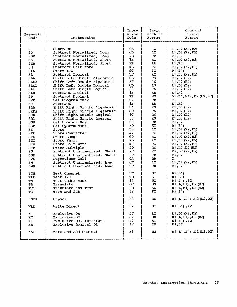
MACHINE INSTRUCTION MNEMONICS
This section contains an alphabetical listing of the mnemonics of all the machine instructions and their operand field formats. The column headings in the list are:
1. Mnemonic Code: This column contains the mnemonic operation code for the machine instruction.
2. Instruction: This column contains the name of the instruction associated with the mnemonic.
3. Operation Code: This column contains the hexadecimal equivalent of the actual machine operation code.
4. Basic Machine Format: This column contains the basic machine format of the instruction:
RR6 RS, RX, SI, or SSe 5. Operand Field Format: This column
shows the explicit symbolic format of the operand and field for the particular mnemonic.
Appendix E provides a table for easy conversion of hexadecimal operation codes to their associated mnemonic codes.

r----------T----------------------------------T-------T----------T----------------------, I I I Oper- I Basic I Operand I I Mnemonic I I ation I Machine I Field I I Code I Instruction I Code I Format I Format I
~----------+----------------------------------+--------+----------+----------------------~
A Add ~)A RX R1 ,D2 (X2,B2) AD Add Normalized, Long 6A RX R1 ,D2 (X2,B2) ADR Add Normalized, Long 2A RR R1,R2 AE Add Normalized, Short 7A RX R 1 , D2 (X2, B2) AER Add Normalized, Short 3A RR R1,R2 AH Add Half-Word ItA RX R1,D2 (X2,B2) AL Add Logical 5E RX R1,D2 (X2,B2) ALR Add Logical 1E RR R1,R2 AP Add Decimal FA SS D1 (L1 ,B1) ,D2 (L2,B2) AR Add 1A RR R1,R2 AU Add Unnormalized, Short 7E RX R1 ,D2 (X2,B2) AUR Add Unnormalized, Short 3E RR R1,R2 AW Add Unnormalized, Long 6E RX R 1 , D2 (X2, B2) AWR Add Unnormalized, Long 2E RR R1,R2
BAL Branch and Link 45 RX R 1 , D2 (X2, B2) BALR Branch and Link 05 RR R1,R2 BC Branch on Condition It 7 RX M1 ,D2 (X2,B2) BCR Branch on Condition 07 RR M1,R2 BCT Branch on Count It6 RX R1 ,D2 (X2,B2) BCTR Branch on Count 06 RR R1,R2 BXH Branch on Index High 86 RS R 1 , R3 , D2 (B2) BXLE Branch on Index Low or Equal 87 RS R 1 , R3 , D2 (B2)
C Compare Algebraic 59 RX R 1 , D2 (X2, B2) CD Compare, Long 69 RX R 1 , D2 (X2, B2) CDR Compare, Long 29 RR R1,R2 CE Compare, Short 79 RX R1,D2(X2,B2) CER Compare, Short 39 RR R1,R2 CH Compare Half-Word 49 RX R1,D2(X2,B2) CL Compare Logical 55 RX R 1 , D2 (X2, B2) CLC Compare Logical D5 SS D1 (L,B1) ,D2 (B2) CLI Compare Logical Immediate 95 SI D1 (B 1) ,12 CLR Compare Logical 15 RR R1,R2 CP Compare Decimal F9 SS D1 (L1 ,B1) ,D2 (L2,B2) CR Compare Algebraic 19 RR R1,R2 CVB Convert to Binary 4F RX R1 ,D2 (X2,B2) CVD Convert to Decimal 4E RX R 1 , D2 (X2, B2)
0 Divide 5D RX R 1 , D2 (X2, B2) DD Divide, Long 6D RX R1 ,D2 (X2,B2) DDR Divide, Long 2D RR R1,R2 DE Divide, Short 70 RX R1 ,D2 (X2,B2) DER Divide, Short 3D RR R1,R2 DP Divide Decimal FD SS D1 (L 1, B1) ,D2 (L2,B2) DR Divide 1D RR R1,R2
ED Edit DE ss D1 (L,B1) ,D2 (B2) EDMK Edit and Mark DF SS D1 (L, B 1) , D2 (B2) EX Execute 44 RX R1 ,D2 (X2,B2)
HDR Halve, Long 24 RR R1,R2 HER Halve, Short 34 RR R1,R2 HIO Halt I/O 9E SI D1 (B 1)
__________ ~ __________________________________ i__. _____ ~ __________ ~ _____________________ _
Machine Instruction Statement 21

r----------T----------------------------------T-------T----------T-----------------o
-----,
I I I Oper- I Basic I Operand I I Mnemonic I I ation I Machine I Field I I Code I Instruction I Code I Format I Format I ~----------+----------------------------------+-------+----------+----------------------~
IC Insert Character 43 RX R 1 ,02 (X2, B2) ISK Insert storage Key 09 RR R1,R2
L Load 58 RX R 1 ,D2 (X2,B2) LA Load Address 41 RX R1,D2 (X2,B2) LCDR I,oad Complement, Long 23 RR R1,R2 LCER I,oad Complement, Short 33 RR R1,R2 LCR Load Complement 13 RR R1,R2 LD Load, Long 68 RX R 1 , D2 (X2, B2) LDR Load, Long 28 RR R1,R2 LE Load, Short 78 RX R 1 , D2 (X2, B2) LER Load, Short 38 RR R1,R2 LH Load Half-Word 48 RX R 1 , D2 (X2, B2) LM Load Multiple 98 RS R 1 , R3 , D2 (B2) LNDR Load Negative, Long 21 RR R1,R2 LNER I.oad Nega ti ve, Short 31 RR R1,R2 LNR Load Negative 11 RR R1,R2 LPDR Load Positive, Long 20 RR R1,R2 LPER Load Positive, Short 30 RR R1,R2 LPR Load Positive 10 RR R1,R2 LPSW Load PSW 82 SI 01 (B1) LR Load 18 RR R1,R2 LTDR Load and Test, Long 22 RR R1,R2 LTER Load and Test, Short 32 RR R1,R2 LTR Load and Test 12 RR R1,R2
M Multiply 5C RX R 1 , D2 (X2, B2) MD Multiply, Long 6C RX R1,D2(X2,B2) MDR Multiply, Long 2C RR R1,R2 ME Multiply, Short 7C RX R 1 , D2 (X2, B2) MER Multiply, Short 3C RR R1,R2 MH Multiply Half-Word 4C RX R1,D2 (X2,B2) MP Multiply Decimal FC SS D1 (L1 ,B1) ,D2 (L2,B2) MR Multiply 1C RR R1,R2 MVC Move Characters D2 SS 01 (L,B1) ,D2 (B2) MVI Move Immediate 92 SI D1 (B 1) ,12 MVN Move Numerics 01 SS D1 (L,B1) ,D2 (B2) MVO Move with Offset F1 SS D 1 (L 1 , B 1) , D2 (L2, B2) MVZ Move Zones D3 SS D1 (L,B1) ,D2 (B2)
N AND Logical 54 RX R1 ,D2 (X2,B2) NC AND Logical D4 SS D1 (L,B1) ,D2 (B2) NI AND Logical Immediate 94 SI D1 (B 1) ,12 NR AND Logical 14 RR R1,R2
0 OR Logical 56 RX R 1 , D2 (X2, B2) OC OR Logical 06 SS D1 (L,B1) ,D2 (B2) 01 OR Logical Immediate 96 SI D1 (B 1) ,12 OR OR Logical 16 RR R1,R2
PACK Pack F2 SS D1 (L1 ,B1) ,D2 (L2,B2)
RDD Read Direct 85 SI D1 (B 1) ,12 __________ ~ __________________________________ i _______ i __________ i _____________________ _
22
r----------T----------------------------------T-------T----------T----------------------, I I I Oper- I Basic I Operand I I Mnemonic I I ation I Machine I Field I I Code I Instruction I Code I Format I Format I
~----------+----------------------------------+-------+----------+----------------------~
S SD SDR SE SER SH SIO SL SLA SLDA SLDL SLL SLR SP SPM SR SRA SRDA SRDL SRL SSK SSM ST STC STD STE STH STM SU SUR SVC SW SWR
TCH TIO TM TR TRT TS
UNPK
WRD
x XC XI XR
ZAP
Subtract Subtract Normalized, Long Subtract Normalized, Long Subtract Normalized, Short Subtract Normalized, Short Subtract Half-Word Start I/O Subtract Logical Shift Left Single Algebraic Shift Left Double Algebraic Shift Left Double Logical Shift Left Single Logical Subtract Logical Subtract Decimal Set Program Mask Subtract Shift Right Single Algebraic Shift Right Single Algebraic Shift Right Double Logical Shift Right Single Logical Set Storage Key Set System Mask Store Store Character Store Long Store Short Store Half-Word Store Multiple Subtract Unnormalized, Short Subtract Unnorrnalized, Short Supervisor Call Subtract Unnormalized, Long Subtr~ct Unnormalized, Long
Test Channel Test I/O Test Under Mask Translate Translate and Test Test and Set
Unpack
Write Direct
Exclusive OR Exclusive OR Exclusive OR, Immediate Exclusive Logical OR
Zero and Add Decimal
5B 6B 2B 7B 3B 4B 9C SF 8B 8F 8D 89 1F FB 04 1B 8A 8E 8C 88 08 80 50 42 60 70 40 90 7F 3F OA 6F 2F
9F 9D 91 DC DD 93
F3
84
57 D7 97 17
F8
RX RX RR RX RR RX SI RX RS RS RS RS RR SS RR RR RS RS RS RS RR SI RX RX RX RX RX RS RX RR RR RX RR
SI SI SI SS SS SI
SS
SI
RX SS SI RR
SS
R1 ,D2 (X2,B2) R1 ,D2 (X2,B2) R1,R2 R1,D2(X2,B2) R1,R2 R1,D2(X2,B2) D1 (B1) R 1 , D2 (X2, B2) R 1 ,D2 (B2) R 1 ,D2 (B2) R 1 ,D2 (B2) R 1 ,D2 (B2) R1,R2 D1 (L1 ,B1) ,D2 (L2,B2) R1 R1,R2 R1 ,D2 (B2) R1,D2 (B2) R 1 ,D2 (B2) R1,D2 (B2) R1,R2 D1 (B 1) R 1 , D2 (X2, B2) R 1 , D2 (X2, B2) R 1 , D2 (X2, B2) R 1 , D2 (X2, B2) R1,D2 (X2,B2) R 1 , R3 , D2 (B2) R1,D2 (X2,B2) R1,R2 I R1,D2(X2,B2) R1,R2
D1 (B 1) D1 (B 1) D1 (B 1) ,12 D1 (L, B 1) , D2 (B2) D1 (L,B1) ,D2 (B2) D1 (B1)
D1 (L1 ,B1) ,D2 (L2,B2)
D1 (B 1) ,12
R1 ,D2 (X2,B2) D1 (L,B1) ,D2 (B2) D1 (B 1) ,12 R1,R2
D1 (L1 ,B1) ,D2 (L2,B2) __________ i __________________________________ L-______ i _ _________ i ______________________ J
Machine Instruction Statement 23
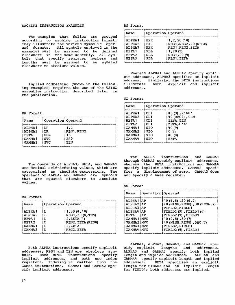
MACHINE INSTRUCTION EXAMPLES
The examples that follow are grouped according to machine instruction format. They illustrate the various symbolic operand formats. All symbols employed in the examples must be assumed to be defined elsewhere in the same assembly. All symbols that specify register numbers and lengths must be assumed to be equated elsewhere to absolute values.
Implied addressing (shown in the following examples) requires the use of the USING assembler instruction described later in the publication.
RR Format r--------T---------T----------------------, I Name I Operation I Operand I ~--------+---------+----------------------~ I ALPHA 1 ILR 11,2 I IALPHA2 ILR IREG1,REG2 1 1 BETA 1 SPM I 15 I I GAMMA 1 ISVC 1250 I 1 GAMMA2 I SVC 1 TEN 1 L ________ i _________ i ______________________ J
The operands of ALPHA1, BETA, and GAMMA1 are decimal self-defining values, which are categorized as absolute expressions. The operands of ALPHA2 and GAMMA2 are symbols that are equated elsewhere to absolute values.
RX Format r--------T----------T---------------------, 1 Name 1 Operation 1 Operand I ~--------+---------+----------------------~ I ALPHA 1 IL 11,39 (4,10) 1 1 ALPHA2 1 L 1 REG 1 , 39 (4, TEN) I 1 BETA 1 IL 12,ZETA(4) I 1 BETA 2 IL IREG2,ZETA(REG4) I 1 GAMMA 1 IL I 2, ZETA I 1 GAMMA 2 IL IREG2,ZETA I L ________ i __________ i ______________________ J
Both ALPHA instructions specify explicit addresses; REG1 and TEN are absolute symbols. Both BETA instructions specify implicit addresses, and both use index registers. Indexing is omitted from the GAMMA instructions. GAMMA 1 and GAMMA2 specify implicit addresses.
24
RS Format r--------T---------T----------------------, I Name 1 Operation 1 Operand I ~--------+---------+----------------------~ IALPHA1 IBXH 11,2,20(14) I I ALPHA2 I BXH I REG 1 , REG2 , 20 (REGE) I IALPHA3 IBXH IREG1,REG2,ZETA I I BETA 1 ISLL 11,20(9) I IBETA2 ISLL IREG1,20(9) I IBETA3 ISLL IREG1,ZETA I L ________ i _________ i ______________________ J
Whereas ALPHA1 and ALPHA2 specify explicit addresses, ALPHA3 specifies an implicit address. Similarly, the BETA instructions illustrate both explicit and implicit addresses.
SI Format r--------T---------T-----------------------, I Name I Operation I Operand I ~--------+---------+-----------------------~ IALPHA1 ICLI 140 (9) ,X w40' I IALPHA2 ICLI 140 (REG9) ,TEN I IBETA1 ICLI I ZETA, TEN I IBETA2 ICLI IZETA,C'A' I I GAMMA 1 ISIO 140(9) I IGAMVA2 ISIO 10(9) I IGAMMA3 ISIO 140{O) I I GAMMA4 I SIO I ZE'l'A I L ________ i _________ i ______________________ J
The ALPHA instructions and GAMMA 1 through GAMMA3 specify explicit addresses, whereas the BE'I'A instructions and GAMMA4 specify implicit addresses. GAMMA2 specifies a displacement of zero. GAMMA3 does not specify a base register.
SS Format r------T---------T------------------------, I Name I Operation I Operand I ~------+---------+-------------------------1 IALPHA11AP 140 (9,8) ,30 (6,7) I IALPHA21 AP 140 (NINE,REG8) ,30 (REG6,7) I IALPHA31 AP IFIELD2,FIELD1 I I ALPHA41 AP I FIELD2 (9) ,FIELD1 (6) I IBETA lAP IFIELD2(9) ,FIELD1 I I GAMMA 1 I MVC I 40 (9, 8) ,30 (7) I IGAMMA21 MVC 140 (NINE,REG8) ,DEC (7) I IGAMMA31MVC IFIELD2,FIELD1 I IGAMMA4 1MVC IFIELD2(9) ,FIELD1 I L _____ i _________ .L _________________________ J
ALPHA1, ALPHA2, GAMMA1, and GAMMA2 specify explicit lengths and addresses. ALPHA3 and GAMMA3 specify both implied length and implied addresses. ALPHA4 and GAMMA 4 specify explicit length and implied addresses. BETA specifies an explicit length for FIELD2 and an implicit length for FIELD1; both addresses are implied.
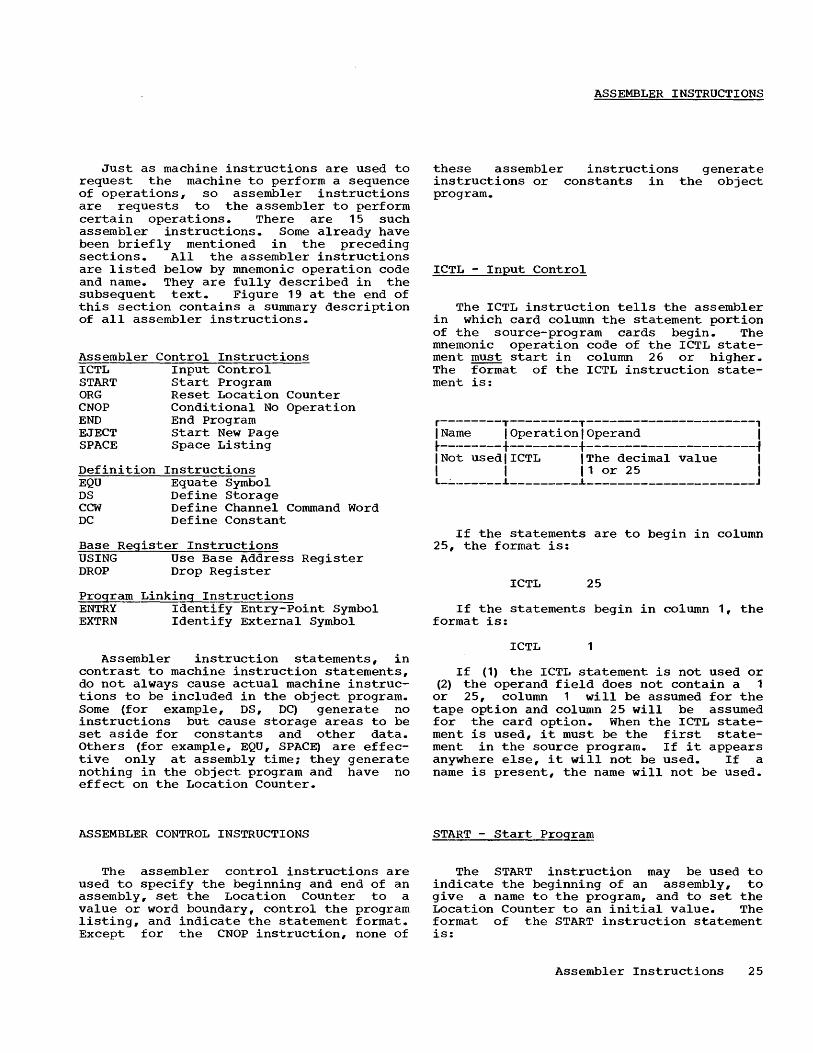
Just as machine instructions are used to request the machine to perform a sequence of operations, so assembler instructions are requests to the assembler to perform certain operations. There are 15 such assembler instructions. Some already have been briefly mentioned in the preceding sections. All the assembler instructions are listed below by mnemonic operation code and name. They are fully described in the subsequent text. Figure 19 at the end of this section contains a summary description of all assembler instructions.
Assembler ICTL START ORG CNOP END EJECT SPACE
Definition EQU DS CCW DC
Control Instructions Input Control Start Program Reset Location Counter Conditional No Operation End Program Start New Page Space Listing
Instructions Equate Symbol Define Storage Define Channel Command Word Define Constant
Base Register Instructions USING Use Base Address Register DROP Drop Register
Program Linking Instructions ENTRY Identify Entry-Point Symbol EXTRN Identify External Symbol
Assembler instruction statements, in contrast to machine instruction statements, do not always cause actual machine instructions to be included in the object program. Some (for example, DS, DC) generate no instructions but cause storage areas to be set aside for constants and other data. Others (for example, EQU, SPACE) are effective only at assembly time; they generate nothing in the object program and have no effect on the Location Counter.
ASSEMBLER CONTROL INSTRUCTIONS
The assembler control instructions are used to specify the beginning and end of an assembly, set the Location Counter to a value or word boundary, control the program listing, and indicate the statement format. Except for the CNOP instruction, none of
ASSEMBLER INSTRUCTIONS
these assembler instructions generate ins1:ructions or constants in the object program.
ICTL - Input Control
The ICTL instruction tells the assembler in which card column the statement portion of the source-program cards begin. The mnemonic operation code of the ICTL statement must start in column 26 or higher. The format of the ICTL instruction statement is:
r--------T---------T----------------------, 1 Name 1 Operation 1 Operand 1 ~---------+---------+----------------------~ INot usedlICTL IThe decimal value 1 1 1 11 or 25 1 L_~ _______ .L _________ .L _____________________ J
If the statements are to begin in column 25, the format is:
ICTL 25
If the statements begin in column 1, the format is:
ICTL 1
If (1) the ICTL statement is not used or (2) the operand field does not contain a 1
or 25, column 1 will be assumed for the tape option and column 25 will be assumed for the card option. When the ICTL statement is used, it must be the first statement in the source program. If it appears anywhere else, it will not be used. If a name is present, the name will not be used.
START - Start Program
The START instruction may be used to indicate the beginning of an assembly, to give a name to the program, and to set the Location Counter to an initial value. The format of the START instruction statement is:
Assembler Instructions 25

r----------T---------T--------------------, I Name I Operation I Operand I ~----------+---------+--------------------1 IA symbol I START IA self-defining I I (optional) I Ivalue or blank I L __________ ~ _________ ~ ____________________ J
The symbol in the name field becomes the name of the program. The symbol is assigned the address corresponding to the self-defining value in the operand field. This symbol can be specified as an external symbol (using the EXTRN instruction) in other programs, without using the ENTRY instruction to identify it as an entry point in this program. If there is no symbol in the name field, the assembler will assign a name consisting of six blanks.
A self-defining value that specifies the initial setting of the Location Counter is written in the operand field. If the value of the operand is not a multiple of eight, the Location Counter will be set at the next double-word boundary. The selfdefining value must not exceed the maximum allowable setting of the Location Counter. If the operand field is invalid or blank, the Location Counter will be set to zero.
The initial setting of the Location Counter becomes -the starting location of the program. This location is the initial loading location if the program is loaded by the absolute loader. It can also be used as the temporary starting location for loading the program while it is being tested. This enables the programmer to match the locations shown in the listing produced by the assembler with the locations in storage print listings. When the program has been checked out, it can then be relocated elsewhere by the relocating loader.
If both the START and ICTL instructions are used, the START instruction must immediately follow the ICTL instruction. If it appears anywhere else or if it is not used, the assembler will set the Location Counter to zero and give the program a name of six blanks. Any invalid occurrences of a START instruction will not be used. It should be noted -that if the ICTL instruction is not used, the START instruction should be the first in the program.
Either of the START statements below could be used to assign the name PROG2 to the program and to set the Location Counter to a value of 2040:
26
PROG2 PROG2
START STAR'r
2040 X' 7F8'
ORG - Reset Location Counter
The ORG instruction resets the Location Counter to a relative value. This instruction may be used anywhere in the program, as often as desired. The format of the ORG instruction statement is:
r--------T---------T----------------------, I Name I Operation I Operand I ~--------+---------+----------------------1 I Not used IORG I A relocatable I I I I expression I L ________ ~ _________ ~ ______________________ J
The Location Counter is reset to the value of the relocatable expression. An ORG instruction that resets the Location Counter below its initial value as specified in the START instruction will not be used; it will, however, be printed in the listing with an error flag. Any symbol (s) in the expression must be previously defined. If the operand field is blank or invalid, the ORG instruction will not be used. If a name is specified, the name will not be used.
The statement:
ORG *+500
increases the Location Counter by 500 above its current setting. Nothing is assembled for the 500 bytes skipped. That is, these bytes are not cleared by the assemble.r.
The ORG instruction provides an alternate way of reserving storage areas; the preferred way usually is with the DS (Define Storage) assembler instruction.
However, where a storage area cannot be conveniently defined with the DS instruction, the ORG instruction can be used. For example, to reserve two storage areas of equal size, the following coding might be used:
TABLE 1
TABLE 2
DS OS
EQU ORG
50F 100H
* *+TABLE2-TABLE1
Note that the EQU assembler instruction permi ts TABLE2 to be used in th'e ORG statement as a previously defined symbol.
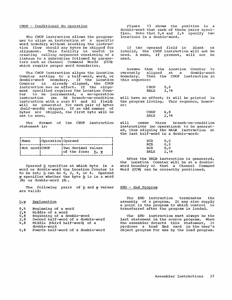
CNOP - Conditional No Operation
The CNOP instruction allows the programmer to align an instruction at a specific word boundary without breaking the instruction flow should any bytes be skipped for alignment. This facility is useful in creating calling sequences consisting of a linkage to a subroutine followed by parameters such as Channel Command Words (CC~ which require proper word boundaries.
The CNOP instruction aligns the Location Counter setting to a half-word, word, or double-word boundary. If the Location Counter is already aligned, the CNOP instruction has no effect. If the alignment specified requires the Location Counter to be incremented, a no-operation instruction (an RR branch-on-condition instruction with a zero R1 and R2 field) will be generated for each pair of bytes (half-words) skipped. If an odd number of bytes are skipped, the first byte will be set to zero.
The format of the CNOP instruction statement is:
r--------T---------T----------------------, I Name I Operation I Operand I ~--------+---------+----------------------~ INot usedlCNOP ITwO decimal values I I I lof the form: ~, ~ I L ________ ~ _________ ~ ______________________ J
Operand ~ specifies at which byte in a word or double-word the Location Counter is to be set; b can be 0, 2, 4, or 6. Operand ~ specifies-whether the byte ~ is in a word (4) or double-word (8).
The following pairs of b and ~ values are valid:
0,4 2,4 0,8 2,8 4,8
6,8
Explanation
Beginning of a word Middle of a word Beginning of a double-word Second half-word of a double-word Middle (third half-word) of a double-word Fourth half-word of a double-word
Figure 13 shows the position in a double-word that each of these pairs specifies. Note that 0,4 and 2,4 specify two locations in a double-word.
If the operand field is blank or invalid, the CNOP instruction will not be used. A name, if present, will not be used.
Assume that the currently aligned boundary. Then the this sequence:
Location Counter is at a double-word
CNOP instruction in
CNOP BALR
0,8 2,14
will have no effect; it will be printed in the program listing. This sequence, however:
CNOP BALR
6,8 2,14
will cause three branch-on-condition instructions (no operations) to be generated, t.hus aligning the BALR instruction at the last half-word in a double-word:
BCR BCR BCR BALR
0,0 0,0 0,0 2,14
After the BALR instruction is generated, the Location Counter will be at a doubleword boundary so that a Channel Command Word (CC~ can be correctly positioned.
END - End Program
The END instruction terminates the assembly of a program. It may also supply a point in the program to which control is transferred after the program is loaded.
The END instruction must always be the last statement in the source program. When the assembler detects this statement, it produces a Load End card in the user's object program for use by the load program.
Assembler Instructions 27

r----------------------------------------------------------------------------------------, I I I Double-Word I I I I I ~-------------------------------------------T-------------------------------------.. ------~ I Word I Word I I I I ~---------------------T---------------------+---------------------T----------------------~ I Half-word I Half-word I Half-word I Half-word I ~----------T----------+----------T----------+----------T----------+----------T-----------~ I Byte I Byte I Byte I Byte I Byte I Byte I Byte I Byte I L __________ .L ___________ .L __________ .L __________ .L __________ .L __________ .L __________ .L ____ . ______ J
0,4 2,4 0,4 2,4 0,8 2,8 4,8 6,8
Figure 13. Boundary Alignment with a CNOP Instruction
The format of the END instruction statement is:
r--------T---------T----------------------, I Name I Operation I Operand I ~--------+---------+----------------------~ INot usedlEND IA relocatable ex- I I I Ipression or blank I L ________ .L _________ .L ______________________ J
The expression in the operand field specifies the point to which control is transferred when loading is complete. The value of the expression will be punched in the Load End card. If the operand field is blank or invalid, nothing will be punched in the Load End card. In this case, control will be passed to the first storage location (above decimal location 128) occupied by the user's program when the program is loaded. If the operand field is invalid, the statement will be flagged as a possible error. If a name is present, it will not be used.
The point to which control usually is transferred is the first machine instruction in the program, as shown in this sequence:
AREA BEGIN
START DS SR
2000 50F 3,3
END BEGIN
EJECT - Start New Page
The EJECT instruction causes the next line of the listing to appear at the top of
28
a new page. This instruction provides a convenient way to separate routines in the program listing. The format of the EJECT instruction statement is:
r--------T---------T----------------------, I Name I Operation I Operand I ~--------+---------+----------------------~ INot usedlEJECT INot used I L ________ .L _________ .L ______________________ J
Normally, the EJECT statement is not included in the program listing; however, anything appearing in the name or operand fields will result in including the statement in the listing. In this case, the EJECT statement is printed prior to skipping to the new page.
SPACE - Space Listing
The SPACE instruction is used to insert one or more blank lines in the listing. The format of the SPACE instruction statement is:
r--------T---------T-----------------------, I Name I Operation I Operand I ~--------+---------+-----------------------~ INot usedlSPACE IA decimal value I L ________ .L _________ .L _______________________ J
A decimal value is used to specify the number of blank lines to be inserted in the program listing. If this value exceeds the number of lines remaining on the listing page, the statement will have the same effect as an EJECT statement. A blank operand field will cause one line to be
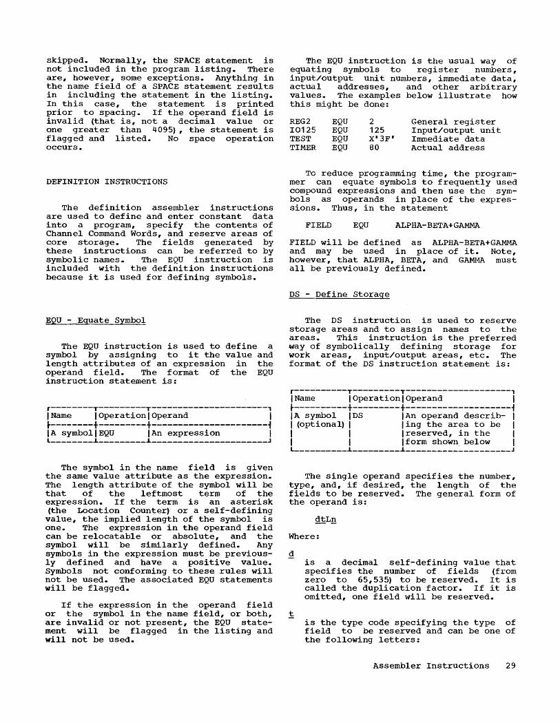
skipped. Normally, the SPACE statement is not included in the program listing. There are, however, some exceptions. Anything in the name field of a SPACE statement results in including the statement in the listing. In this case, the statement is printed prior to spacing. If the operand field is invalid (that is, not a decimal value or one greater than 4095), the statement is flagged and listed. No space operation occurs.
DEFINITION INSTRUCTIONS
The definition assembler instructions are used to define and enter constant data into a program, specify the contents of Channel Command Words, and reserve areas of core storage. The fields generated by these instructions can be referred to by symbolic names. The EQU instruction is included with the definition instructions because it is used for defining symbols.
EQU ~ Equate Symbol
The EQU instruction is used to define a symbol by assigning to it the value and length attributes of an expression in the operand field. The format of the EQU instruction statement is:
r--------T---------T----------------------, I Name I Operation I Operand I ~-------+---------+----------------------~ IA symbollEQU IAn expression I L ________ ~ _________ ~ ______________________ J
The symbol in the name field is given the same value attribute as the expression. The length attribute of the symbol will be that of the leftmost term of the expression. If the term is an asterisk (the Location Counter) or a self-defining
value, the implied length of the symbol is one. The expression in the operand field can be relocatable or absolute, and the symbol will be similarly defined. Any symbols in the expression must be previously defined and have a positive value. Symbols not conforming to these rules will not be used. The associated EQU statements will be flagged.
If the expression in the or the symbol in the name are invalid or not present, ment will be flagged in will not be used.
operand field field, or both, the EQU statethe listing and
The EQU instruction is the usual way of equating symbols to register numbers, input/output unit numbers, immediate data, actual addresses, and other arbitrary values. The examples below illustrate how this might be done:
REG2 10125 TEST TIMER
EQU EQU EQU EQU
2 125 X'3F' 80
General register Input/output unit Immediate data Actual address
To reduce programming time, the programmer can equate symbols to frequently used compound expressions and then use the symbols as operands in place of the expressions. Thus, in the statement
FIELD EQU ALPHA-BETA+GAMMA
FIELD will be defined as ALPHA-BETA+GAMMA and may be used in place of it. Note, however, that ALPHA, BETA, and G~~ must all be previously defined.
DS - Define Storage
The DS instruction is used to reserve storage areas and to assign names to the areas. This instruction is the preferred way of symbolically defining storage for work areas, input/output areas, etc. The format of the DS instruction statement is:
r----------T---------T--------------------, I Name I Operation I Operand I ~----------+---------+--------------------~ IA symbol IDS IAn operand describ- I I (optional) I ling the area to be I I I I reserved, in the I I I Iform shown below I L __________ i _________ ~ ____________________ J
The single operand specifies the number, type, and, if desired, the length of the fields to be reserved. The general form of the operand is:
Where:
is a decimal self-defining value that specifies the number of fields (from zero to 65,535) to be reserved. It is called the duplication factor. If it is omitted, one field will be reserved.
is the type code specifying the type of field to be reserved and can be one of the following letters:
Assembler Instructions 29

Ln
C H F D
ImElied Length Field TYEe (in Bytes)
Character (byte) 1 Half-word 2 Full-word 4 Double-word 8
can be used only if the field code is C. L~ is the length code written as the letter L immediately followed by ~, which is the length (in bytes) of each field. n can be a decimal value that is not zero-or greater than 256.
Half-word, full-word, and double-word fields will be aligned to their proper boundaries. With a duplication factor (~ of zero, the DS instruction can be used to cause boundary alignment. Thus, the statement:
DS OD
will set the Location Counter at the next double-word boundary.
If there is a symbol in the name field, it will be assigned the current value of the Location Counter after any alignment. The length attribute of the symbol will be the implied length associated with the field code, unless a length code (Lm is specified, in which case the length attribute will be the same as the length g.
For example, to define four 10-byte fields and one 100-byte field, the respective DS statements might be:
FIELD AREA
DS DS
4CL10 CL100
Then, to move the first 10 bytes at AREA into FIELD,the coding 1S as follows, assuming implied base registers and displacements:
MVC FIELD, AREA
Note that the length attribute off FIELD, which is 10, is implied. Explicit length specification can be used to move the first 20 bytes at AREA into FIELD. The following instruction illustrates this:
MVC FIELD (20) ,AREA
Additional examples of DS statements are shown below. The implied length . attribute of each symbol appears in parentheses before the symbol:
30
(80) DONE DS CL80 One 80-byte field (1) DTWO DS 80C 80 one-byte fields (4) DTHREE DS 6F Six full-words (8) DFOUR DS D One double-word (2) DFIVE DS 4H Four half-words
If the operand is incorrectly specified, the statement will not be used. An error flag will appear in the listing.
A DS statement causes the reserved area to be skipped but not cleared. Therefore Q
the progra~ner should not assume that the area contains all zeros when the program is loaded. Whenever the assembler processes a DS statement, it will terminate the current output card (called a Text card) in the object deck and start the next card at the location following the reserved areas, thus skipping them. To minimize the number of Text cards punched, DS statements should be kept together as much as possible. Note, however, that Text cards are not terminated if no bytes are skipped by DS statements used only for boundary alignment.
CCW - Define Channel Command Word
The CCW instruction provides a convenient way to define and generate an eightbyte Channel Command Word aligned at a double-word boundary. The internal machine format of a Channel Command Word is shown in Figure 14. The format of a CCW instruction statement is:
r----------T---------T-------------·-------, I Name I Operation I Operand I ~----------+---------+--------------------i IA symbol ICCW IFour operands, I I (optional) I I separated by commas, I I I Ispecifying the I I I Icontents of the I I I IChannel Command I I I I Word in the form I I I Idescribed below I L __________ ~ _________ ~ ____________________ J
The four operands, from left to right, are:
1. A simEle absolute expression specifying the command code. The value of this expression will be rightjustified in byte 1.
2. A relocatable expression specifying the data address. The value of this expression will be right-justified in bytes 2-4.
3. A simple absolute expression specifying the flags in bits 32-36 and zeros in bits 37-39. The value of

this expression is right-justified in byte 5. Byte 6 is set automatically to all zeros.
4. A simple absolute expression specifying the count. The value of this expression is right-justified in bytes 7-8.
The following is an example of a CCW statement:
CCW X'OF',READIN,X'A8',80
Note that the form of the third operand sets bits 37-39 to zero, as required. The bit pattern of this operand is:
32 1010
36 1000
40 0000
44 0000
No operand field may be omitted. Operands not used must be written as zeros. An error in the operand field will cause eight bytes of zeros, aligned at a double-word boundary, to be assembled.
If there is a symbol in the name field, it will be assigned the value of the leftmost byte of the Channel Command Word after any boundary alignment. The length attribute of the symbol will be eight. Bytes skipped because of alignment will be assembled as zeros.
r--------T---------T----------------------, I Byte I Bits I Usage I ~--------+---------+----------------------~
1 0-7 Command code
2-4 8-31 Data address
32-36 Flags 5
37-39 Must be zero
6 40-47 Assembled automati-cally as all zeros
7-8 48-63 Count ________ i _________ i _____________________ _
Figure 14. Channel Command Word
DC - Define Constant
The DC instruction is for generating constant data in main storage. Data can be specified as characters, hexadecimal numbers, decimal numbers, and storage addresses. Decimal numbers may be in the form suitable for both fixed-point and floatingpoint arithmetic operations. The format of the DC instruction statement is:
r----------T---------T--------------------, I Name I Operation I Operand I ~----------+---------+--------------------~ I A symbol I DC I A single operand I I (optional) I Idescribing the I I I Iconstant, written inl I I I the form shown below I L __________ i _________ i ____________________ J
~rhe operand specifies the type of constant and the constant itself. It may also specify an explicit storage length for the constant and indicate how many times the constant is to be duplicated in storage. The format of this operand varies with the constant type. The basic format is either
where:
is a decimal self-defining value (from 1 to 65,535) that specifies the number of identical constants to be generated. It is called the duplication factor. If it is omitted, one constant will be produced. A duplication factor cannot be specified for an expression (type A) constant.
Note: A print line is produced for each constant generated. Thus, assembler speed can be increased by keeping duplication factors small and length codes large.
t
C
x
F
E
H
D
A
is the type code, specifying the type of constant. It can be one of the following letters:
Constant ~
character
hexadecimal
decimal
decimal
decimal
decimal
relocatable or absolute expression
Machine Format
8-bit BCD code.
Fixed-point binary.
Full-word fixedpoint binary.
Short-precision floating-point binary.
Half-word fixedpoint binary.
Lc;:mg-precision floating-point binary.
Fixed-point binary.
Assembler Instructions 31

'~'
is the length code written as the letter L followed by n, a decimal value, which is the explicit length (in bytes) of the constant. A length code is not applicable with constant types H, E, and D. If a length code is not given, the implied lengths shown in Figure 15 will be used. An explicit length must not exceed those values shown in Figure 15.
is the constant itself enclosed in single quotation marks. Note that for constant type A, the expression specifying the constant is enclosed in parentheses (£).
If the operand is invalid, the statement will not be used and will be flagged in the listing.
All constant types except character (C) and hexadecimal (X) will be aligned at appropriate boundaries. Constants are not aligned if an explicit length is given. The boundaries for the various constant types are summarized in Figure 15. Any bytes skipped for alignment will be set to zero.
A symbol in the name field will be given the address value of the first byte assigned after any alignment. The length attribute of the symbol will be the implied (or explicit) length of the constant before the duplication factor is applied.
The implied or explicit length of a constant defined by a single DC statement must not exceed 16 bytes before the duplication factor is applied. If longer constants are required, successive DC statements should be used. The total storage alloted to a constant defined by one DC statement will be the duplication factor times the length of the constant.
The subsequent text, with examples, describes each of the constant types. This material is summarized in Figure 15. Note that the definition of character, hexadecimal, and decimal constants is not limited by the rules pertaining to self-defining values.
Character Constants (C)
A character constant may comprise not more than 16 valid characters. A valid
32
character is a blank or any combinati.on of punches in a card column that translates into the 8-bit IBM Extended BCD Interchange Code. There are 256 such combinations; the table in Appendix A lists the combinations, their eight-bit codes, and, where applicable, their printer graphics.
Each character in the constant is translated into one byte. Boundary ali.gnment is not performed. 'rhe number of bytes required for the constant becomE~s its implied length unless an explicit length is stated. In the following examplE~, the length attribute of FIELD is 12:
FIELD DC C'TOTAL IS 10'
A single quotation mark used as a character is represented in the constant by two single quotation marks. The same rule applies to ampersands. Thus:
DC C'DON"T' DC C'A,B&&C'
Five bytes will be used for each constant.
If more than 16 characters are spE~cified or a length code is given and the si.ze of the constant exceeds the explicit length, the excess rightmost characters will be truncated before applying the duplication factor. The statement will be flagged. For example, the statement:
DC 3CL4'ABCDE'
will generate:
ABCDABCDABCD
If the number of characters is fewer than the explicit length, the constant will be padded by adding the necessary righthand blanks. The statement:
DC 4CL3,' NO'
will generate in storage:
NOb NObNObNOb
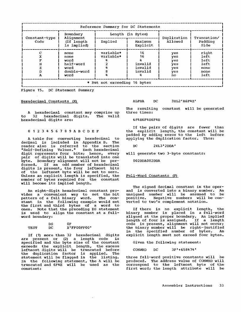
r---------------------------------------------------------------------------------------, I Reference Summary for DC Statements I ~---------------T---------------T---------------------------T-------------T-------------~ I I Boundary I Length (in Bytes) I I I I Constant-type I Alignment I-------------T-------------I Duplication I Truncation/ I I Code I (If length I Implied I Maximum I Allowed I Padding I I I is implied) I I Explicit I I Side I
~---------------+---------------+-------------+-------------+-------------+-------------~ I C I none I variable* I 16 I yes I right I I X I none I variable* I 16 I yes I left I I F I word I 4 I 4 I yes I left I I H I half-word I 2 I invalid I yes I left I I E I word I 4 I invalid I yes I none I I D I double-word I 8 I invalid I yes I none I I A I word I 4 I 4 I no I left I ~---------------~---_-----------~-------------L--------_____ ~ _____________ ~ _____________ ~ I * But not exceeding 16 bytes I L _______________________________________________________________________________________ J
Figure 15. DC Statement Summary
Hexadecimal Constants (X)
A hexadecimal constant may comprise up to 32 hexadecimal digits. The valid hexadecimal digits are:
o 1 234 5 6 7 8 9 ABC D E F
A table for converting hexadecimal to decimal is included in Appendix B. The reader also is referred to the sect~on "Self-Defining Values." Each hexadecimal digit represents four bits; hence, every pair of digits will be translated into one byte. Boundary alignment will not be performed. If an odd number of hexadecimal digits is present, the four leftmost bits of the leftmost byte will be set to zero. Unless an explicit length is specified, the number of bytes required for the constant will become its implied length.
An eight-digit hexadecimal constant provides a convenient way to set the bit pattern of a full binary word. The constant in the following example would set the first and third bytes of a word to ones. Note that the preceding DS statement is used to align the constant at a fullword boundary:
TEST DS DC
OF X'FFOOFFOO'
If (1) more than 32 hexadecimal digits are present or (2) a length code is specified and the byte size of the constant exceeds the explicit length, the excess leftmost digits will be truncated before the duplication factor is applied. The statement will be flagged in the listing. In the following statement, the A will be truncated and 6F4E will be used as the constant:
ALPHA DC 3XL2'A6F4E'
The resulting constant will be generated three times:
6:F4E6F4E6F4E
If the pairs of digits are fewer than the explicit length, the constant will be padded by adding zeros to the left before applying the dUplication factor. Thus:
DC 2XL3'2DDA'
will generate two 3-byte constants:
002DDA002DDA
Full-Word Constants (F)
The signed decimal constant in the operand is converted into a binary number. An unsigned number will be assumed to be posi,tive. Negative numbers will be converted to two's complement notation.
If there is no explicit length, the binary number is placed ~n a full-word aligned at the proper boundary. An implied leng·th of four is assigned. If a length code is present, alignment will not occur; the binary number will be right-justified in ·the specified number of bytes. An explicit length must not exceed four bytes.
Given the following statement:
CON"ilRD DC 3F'+658474'
three full-word positive constants will be produced. The address value of CONWRD will correspond to the leftmost byte of the firs·t word; the length attribute will be
Assembler Instructions 33

four. Thus, the expression CONWRD+4 can be used to address the second word symbolically.
The maximum permissible value of a fullword constant depends on the length, as follows:
Length Highest Value Lowest Value
4 3 2 1
2,147,483,647 8,388,607
32,767 127
-2,147,483,648 -8,388,608
-32,768 -128
Note: All lengths can be explicit. A length of 4, however, can also be implied.
If a value exceeds the limits associated with the length, a constant of zero will be generated before applying the duplication factor. The statement will be flagged in the listing. For example, the following statement would generate 12 bytes of zeros:
DC 4FL3'-9500250'
Half-Word Constants (H)
The signed decimal constant in the is converted into a binary number in a properly aligned half-word. A
code is not allowed. The implied of the constant is two bytes.
operand placed length length
If the number is unsigned, a positive value is assumed. Negative numbers will be converted to two's complement notation.
The largest number permitted is 32,767; the smallest is -32,768. If a number exceeds these limits, the constant will be set to zero before the duplication factor is applied. The statement will be flagged.
The following statement will generate two identical half-word positive constants, right-justified within two bytes:
DC 2H'256'
Short-Precision Floating-poin~ Constants (E)
A short-precision floating-point constant is specified as a decimal fraction (mantissa) and an optional decimal exponent. The maximum allowable range for a floating-point constant is from approximately (5.4)x10-79 to (7.2)x10 75 • The constant will be aligned at a full-word bound-
34
ary in the proper machine format for use in floating-point operations. A duplication factor may be applied to the const;ant. A length code, however, may not be used.
The format of the constant port;ion of the operand is described in the following text.
Fraction: The fraction is a signed decimal number (up to 8 digits) with or without a decimal point. The decimal point can appear before, within, or after the number. If the point is at the right-hand end of the number, it may be omitted. If the sign is omitted, a positive fraction is assumed. A negative fraction is carried in the machine in true form. The fraction, irrespective of its decimal point or sigrn, must not exceed 2 to the 24th power minus 1 (i.e., 16,777,215). The fraction part of a
number converted to the short format will differ by no more than 1 from the exact value rounded to 24 places.
Exponent: The exponent is optional. It may be omitted if the decimal point appears in the fraction at the desired position. If the exponent is specified, i.t must immediately follow the fraction. It consists of the letter E followed by a signed decimal number denoting the exponent~ to the base ten. A positive exponent is assumed if the sign is omitted.
A negative exponent indicates that the true decimal point is to the left of the point written (or assumed) in the fraction. A posi ti ve exponent indicates that t~he true decimal point is to the right. The value of the exponent determines how many places to the left or right the true decima.l point is located.
For example, to convert the number 46.415 to a floating-point format, any of the following statements could be used. They will all have the same effect:
DC DC DC DC DC
E'46.415' E'46415E-3' E'+46415.E-3' E'.46415E2' E'4.6415E+1'
If either the fraction or the E!xponent is outside the permissible range, the full word (or words, if a duplication fa.ctor is specified) will be set to zero and a flag will appear in the listing. The sta.tement:
DC 4E'3.45E76'
would generate four full-words of ZE!ros.

Long-Precision Floating-Point Constants (0)
A long-precision floating-point constant is specified as a decimal fraction (mantissa) and an optional decimal exponent. The maximum allowable range for a floating-point constant is from approximately (5.4)x10- 79 to (7.2)x10 75 • The constant will be aligned at a double-word boundary in the proper machine format for use in floating-point operations. A duplication factor may be applied to the constant. A length code, however, may not be used.
The format of the constant portion of the operand is described in the following text.
Fraction: The fraction is a signed decimal number (up to 17 digits) with or without a decimal point. The decimal point can appear before, within, or after the number. If the point is the right-hand end of the number, it may be omitted. If the sign is omitted, a positive fraction is assumed. A negative fraction is carried in the machine in true form. The fraction, irrespective of its decimal point or sign must not exceed 2 to the 56th power minus 1 (that is, 72,057,594,037,927,935). The fraction part of a number converted to the long format will differ by no more than 11 from the exact value rounded to 56 places.
Exponent: The exponent is optional. It may be omitted if the decimal point appears in the fraction at the desired position. If the exponent is specified, it must immediately follow the fraction. It consists of the letter E followed by a signed decimal number denoting the exponent to the base ten. A positive exponent is assumed if the sign is omitted.
A negative exponent indicates that the true decimal pOint is to the left of the point written (or assume~ in the fraction. A positive exponent indicates that the true decimal point is to the right.· The value of the exponent determines how many places to the left or right the true point is located.
If either the fraction or exponent is outside the permissible range, the double word (or words, if a duplication factor is specified) will be set to zero. The statement will be flagged.
The following statements illustrate different ways of converting the same number to a long-precision floating-point number:
OC 0'-72957' OC 0'-729.57E+2' OC 0'-729.57E2' OC 0'-.72957E5' OC 0'-7295700.E-2'
Expression Constants (A)
An expression constant consists of a relocatable or absolute expression enclosed in parentheses instead of single quotation marks. The value of the expression is generated as a 32-bit value constant. Since the expression frequently represents a storage address, the constant generated from it is commonly called an address constant. Hence, the letter A is used as the type code. Note that if the program is relocated, all address constants generated from relocatable expressions will be changed by the relocating program loader.
An explicit length not exceeding four bytes may be specified for express10n constants. However, a duplication factor is not allowed.
Unless a length code is present, the 32-bit constant will be aligned at a fullword boundary and given an implied length of four. ThUS, in the following statement, the value of AREA+2, as a 32-bit value, will be placed in the next available full word. ADCON1 will be given a length attribute of four:
ADCON1 OC A (AREA+2)
If a length code is given, the constant will not be aligned. The constant will be right-justified in the specified number of bytes. Any excess bits to the left will be truncated. For example, in the statement:
ADCON2 OC AL2 (FIELO-256)
the rightmost 16 bits of the value of FIELD-256 will be right-justified in the next two bytes. The length attribute of ADCON2 will be two. In this case, FIELO must be equivalent to an absolute symbol. (see below.)
'rhe following considerations govern type A constants:
1. A relocatable expression may be used only if the length is implied (that is, it is four) or if the explicit length is three or four.
2. An expression may have a negative value only if it is an absolute expression. A negative value will be stored in two's complement notation.
3. An expression may not begin with an arithmetic operator.
Assembler Instructions 35

BASE REGISTER INSTRUCTIONS
The USING and DROP base register assembler instructions enable programmers to use expressions representing core storage locations as operands of machine instruction statements, lea'V'ing the assignment of base registers and the calculation of displacements to the assembler.
This feature of the assembler, besides simplifying programming, also will eliminate a likely source of programming errors, thus reducing the time required to check out programs. To take advantage of this feature, the programmer must use the USING and DROP instructions described in this section.
USING - Use Base Address Register
The USING instruction indicates that the general register specified in the operand is available for use as a base register. This instruction also states the baseaddress value that the assembler must assume is in 'the register at object time. Note that a USING instruction does not load the register specified. It is the programmer's responsibility to see that the specified base-address value is placed into the register. Suggested loading methods are described in the section ·Programming with the USING and DROP Instructions." The format of the USING instruction statement is:
r--------T---------T----------------------, I Name I Operation I Operand I ~--------+---------+----------------------i INot usedlUSING IA relocatable expres- I I I Ision and a simple I I I labsolute expression, I I I I separated by a comma I L ________ ~ _________ ~ ______________________ J
The relocatable expression specifies a value that the assembler can use as a base address. The second operand is a simple absolute expression specifying the general register that can be assumed to contain the base address represented by the first operand. The value of the second operand must be from 1 to 15. For example, the statement:
USING *,12
tells the assembler it may assume that the current value of the Location Counter will be in general register 12 at object time.
36
If the programmer changes the value in a base register currently being used, the assembler must be told the new value by means of another USING statement. In the following sequence, ALPHA is a relocatable expression:
USING ALPHA, 9
USING ALPHA+1000,9
The assembler will first assume that the value of ALPHA is in register 9. The second statement causes the assembler to assume ALPHA+1000 as the value in register 9.
If the value of the second operand is zero, implying no base addressing, the first operand should also have a value of zero. If it does not, zero will be used instead of the actual value and the statement will be flagged in the listing. The implications of using register zero as a base register are discussed later in "Base Register Zero."
A USING statement will not be used if either of its operands are incorrect. A flag will appear in the listing. Any symbol in the name field will not be used.
DROP - Drop Register
The DROP instruction specifies viously available register that longer be used as a base register.
a premay no
r--------T---------T----------------'------, I Name I Operation I Operand I ~--------+---------+----------------,------i I Not used I DROP I A simple absolute I I I I expression I L ________ ~ _________ ~ ________________ , ______ J
The expression indicates a general register that previously had been named in a USING statement and now is unavailable for base addressing. The following statement, for example, removes register 11 from the list of available registers:
DROP 11
The DROP statement is ignored if the register it designates had never appeared in a USING statement. If the value of the expression exceeds 15, the statemen·t will not be used and will be flagged in the listing. Any symbol in the name field will not be used.
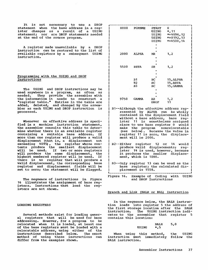
It is not necessary to use a DROP statement when the base address in a register changes as a result of a USING statement; nor are DROP statements needed at the end of the source program.
A register made unavailable by a DROP instruction can be restored to the list of available registers by a subsequent USING instruction.
Programming with the USING and DROP Instructions
The USING and DROP instructions may be used anywhere in a program, as often as needed. They provide the assembler with the information it needs to construct a -register table.- Entries in the table are added, deleted, and changed by the assembler as each USING and DROP instruction is processed.
Whenever an effective address is specified in a machine instruction statement, the assembler consults this table to determine whether there is an available register containing a suitable base address. If more than one register will produce a valid displacement (that is, a displacement not exceeding 4095), the register whose contents produce the smallest displacement will be used. If two or more registers will produce the same displacement, the highest numbered register will be used. If there is no register that will produce a valid displacement, the corresponding base register and displacement fields will be set to zero; the statement will be flagged.
The sequence of instructions in Figure 16 illustrates the assignment of base registers. Instructions that load the registers are not shown.
LOADING REGISTERS
Several methods exist for loading general registers that will be used for base addressing. However, for a program to be relocated when it is loaded, at least one of the base registers must be loaded with a relocatable address, using either of the instructions described below. The exact method of using these instructions can differ from the examples shown.
r-----------------------------------------, 0000 PGMNME START 0
2000 ALPHA
5500 BETA
B1 B2 B3
9750 GAMMA
USING *,11 USING *+4096,12 USING *+8192,13 USING *+4500,14
MR
SR
BC BC BC
AR DROP
1,2
1,2
15,ALPHA 15,BETA 15, GAMMA
1,2 11
B1--Although the effective address represented by ALPHA can be wholly contained in the displacement field without a base address, base register 11 is nonetheless assigned since to use base register 0 would make the program nonrelocatable (see below). Because the value in register 11 is zero, the displacement will be 2000.
B2-'-Either register 12 or 14 would produce valid displacements; register 14 is used, however, because it produces the smaller displacement, which is 1000.
B3--0nly register 13 can be used as the base register; the calculated displacement is 1558. _________________________________________ J
Figure 16. Example of Coding with USING and DROP Instructions
Branch and Link (BALR or BAL) Instruction
In the sequence below, the BALR instruction loads into register 5 the address of the first storage location after the BALR instruction. The USING instruction indicates to the assembler that register 5 contains this location:
BALR 5,0 USING *,5
When using this method, the USING instruction must immediately follow the BALR instruction.
Assembler Instructions 37

Load Full-Word (~ Instruction
In the following coding, the value of RGLOAD is generated as a constant. RGLOAD is some symbol defined elsewhere in the program. This value, which is also specified in the USING instruction, is inserted into register 6 with the Load (~ instruction.
CNSTNT DC A (RGLOAD)
L 6,CNSTNT
USING RGLOAD,6
Note that if the symbol RGLOAD was used in the load instruction, register 6 would contain the full-word located at RGLOAD rather than the value of RGLOAD itself.
The Load instruction should precede the USING instruction to insure that the assumed contents of the register are, in fact, in the register when the program is executed. Otherwise, the assembler would use the specified register as a base register in machine instructions before the load instruction was encountered. This could lead to undesirable results when the program is executed. Observe, however, that the USING instruction need not immediately follow the load instruction, although it is recommended that the two instructions be consecutive ..
If one register has been initialized by the Branch-and-Link or Load instruction, other registers may be loaded from it by other instructions. Thus, in the following example, the Load Address (LA) instruction causes 4,080 to be added to the contents of register 4 and the resulting total to be placed in register 3:
HERE
BALR USING LA
USING
4,0 HERE, 4 3,4080 (0,4)
HERE+4080,3
Note that the LA instruction could have been written alternately as LA 3,4080(4).
Base-Register Zero
The specification of general register 0 as a base register indicates that a quantity of zeLO is to be used as the base
38
address, regardless of the contents of general register O. Therefore, if general register 0 is made available by a USING instruction for base addressing, the program will not be relocatable when there is no other general register available for referencing locations below location 4096. Figure 17 illustrates a program that would not be relocatable; any reference to AREA 1 will require the use of register 0, since register 2 cannot produce a valid displacement. References to AREA2, howeve:r, will make use of register 2.
This restriction does not prcevent a relocatable program from referring to actual storage locations by means of absolute expressions. For example, to reference a permanently allocated interrupt location at storage address 24, the following statement is perfectly correct:
LPSW 24
r------------------------------------------, 0000 START 0
USING *,0 USING *+2048,2
2000 AREA 1 DS 20H
4000 AREA2 DS 10F
Figure 17. Example of Coding Using Base Register Zero
PROGRAM LINKING INSTRUCTIONS
The program linking assembler instructions allow the programmer to symbolically link independently assembled programs that will be loaded and executed together. Symbolic linkages between programs are created by means of symbols that are defined in one program and used as operands in another program. Such symbols are termed linkage symbols. A linkage symbol is called an Rentry-point symbolw in the program in which it is defined; it is an Wexternal symbolW in the program in which it is used as an operand. External and entry-point symbols are also described in the section wSymbols. w
Every linkage symbol must be properly identified as such in the source program. A linkage symbol used as an external symbol is identified in each using program by the EXTRN instruction. A linkage symbol used

as an entry point must be identified in the defining program by the ENTRY instruction.
A program name (defined in the name field of a START statement) is also considered an entry point. A program name, however, does not have to be identified as an entry point by the ENTRY instruction.
ENTRY - Identify Entry-Point Symbol
The ENTRY instruction identifies an entry-point symbol to the program. Each such entry-point symbol (except a program name) must be identified by a separate ENTRY instruction. The format of the ENTRY instruction statement is:
r--------T---------T----------------------, I Name I Operation I Operand I ~--------+---------+----------------------~ INot usedlENTRY IA relocatable symbol I L ________ ~ _________ ~ ______________________ J
The relocatable symbol in the operand field is a symbol defined elsewhere in the program, which may be used as an entry point by other programs. A symbol that is not defined in the program will be flagged in the listing as an undefined symbol. Any symbol in the name field will not be used.
An ENTRY statement must be immediately preceded by either the START statement, an EXTRN statement, or another ENTRY statement. It cannot appear in a program unless the START statement has been used.
If an ENTRY statement placed or if the operand is statement will not be used. will appear in the listing.
is incorrectly invalid, the An error flag
In the following sequence, SQRT is identified as an entry-point symbol. Note that the ENTRY statement appears immediately after the START statement:
SUBRO
SQRT
START ENTRY
STM
o SQRT
1,10,SAVE
EXTRN - Identify External Symbol
The EXTRN instruction identifies a linkage symbol as an external symbol that will be referred to in this program. Each such
external symbol must be identified by a separate EXTRN instruction. The format of the EXTRN instruction statement is:
r--------T---------T----------------------, I Name I Operation I Operand I ~--------+---~-----+----------------------~ I Not used I EXTRN I A relocatable symbol I L ________ ~ _________ ~ ______________________ J
The relocatable symbol in the operand field must be defined in another program, and identified in that program as an entrypoin·t symbol by either the START or ENTRY instruction. Any symbol in the name field will not be used.
An EXTRN statement must be immediately preceded by either the START statement, an ENTRY statement, or another EXTRN statement. An EXTRN statement cannot appear in a program unless the START statement has been used. Not more than 14 EXTRN statements may appear in a program. If there are more than 14 statements, the symbol in each excess statement will be flagged as undefined.
If an EXTRN statement placed or if the operand is statement will not be used. will appear in the listing.
is incorrectly invalid, the An error flag
As an example, if MTPLY is an entrypoin"t symbol in another program, the using program identifies it as an external symbol, thus:
EXTRN MTPLY
The correct use of an external symbol elsewhere in a program is described below.
LINKING CONVENTIONS
The only way that an external symbol may be referenced is to (1) identify it with the EXTRN instruction, (2) create an address constant from the external symbol, (3) load the constant into a general register, and (4) branch to the address via the register or use the register for base addressing.
For example, to link to a program named SINE, the following coding might be used:
Assembler Instructions 39

PROGA START 1000 EX'J.'RN SINE
L 4,ADSINE BALR 15,4
ADSINE DC A (SINE)
In this example, SINE would be given a value of zero at assembly time; four bytes of zeros would be reserved at the symbolic location ADSINE. When the programs are loaded, the relocating loader will add to the four bytes of zeros the effective address assigned to SINE.
If the programmer wished to link, say, to a location 12 bytes past SINE, the constant could be created as follows:
ADSINE DC A (SINE+12) ,
The relocating program loader will add 12 to the effective address of SINE and place the sum in the four bytes at ADSINE. The expression in which the external symbol is used must be a relocatable expression.
Another method of linking to SINE+12 is:
{ { {
ADSINE
START EXTRN
USING L
BAL BAL BAL
DC
1000 SINE
SINE, 4 4,ADSINE
15,SINE+12 15,12 (0,4) 15,12(4)
A (SINE)
} } }
In the above sequence, either BAL instruction can be used; if BAL 15,12(0,4) or BAL 15,12(4) is used, the USING statement may b~ omitted, since implicit base addressing is not involved.
A return branch from the program named SINE may be made via the registers without making any reference to a linkage symbol. Thus, if the branch to SINE was:
40
BALR 10,4
the return branch may be:
BCR 15,10
Limitations on Program Linking
The order in which independently assembled programs are loaded generally determines the extent to which they can link to one another. The program(s) containing the entry point(s) must be loaded before the program (s) that will reference these' points as external symbols. Note, however, that program names are not affected by this restriction. A program loaded first may refer to programs loaded after it by their names, using the facilities of the relocating loader. In addition, the use of relocating loader control cards can remove all restrictions on linking.
In the following situation, two independently assembled programs, Program A and Program B, are to be executed together. Each program contains the coding shown in Figure 18.
If Program A is loaded first, it can refer to Program B only by its name, PROGB. Program B however, can refer to Program A by its name, PROGA, and its entry points, LOOP and LINK. If the loading order is reversed, then Program B can refer to Program A only by its name, whereas Program A can refer to Program B by its name and by its entry points, SINE and COSINE.
Thus, if a common data area is to be used by two independently assembled programs, the data area should be assembled separately and then loaded first to enable both programs to refer freely to it.
Program Relocation and Linking
Programs that will be linked together at object time must be relocatable. To be relocatable, a program must:
1. Contain all the information required by the relocating loader.
2. Not use absolute expressions to refer to any area that can be relocated.
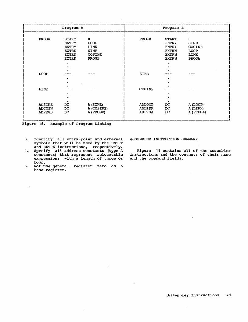
r------------------------------------------T------·--------------------------------------, I Program A I Program B I .------------------------------------------+-----_._-------------------------------------~
PROGA
LOOP
LINK
ADSINE ADCOSN ADPRGB
START ENTRY ENTRY EXTRN EXTRN EXTRN
DC DC DC
0 LOOP LINK SINE COSINE PROGB
A (SINE) A (COSINE) A (PROGB)
PROGB
SINE
COSINE
ADLOOP ADLINK ADPRGA
START ENTRY ENTRY EXTRN EXTRN EXTRN
DC DC DC
0 SINE COSINE LOOP LINK PROGA
A (LOOP) A (LINK) A (PROGA)
------------------------------------------~--------------------------------------------Figure 18. Example of Program Linking
3. Identify all entry-point and external symbols that will be used by the ENTRY and EXTRN instructions, respectively.
4. Specify all address constants (type A constants) that represent relocatable expressions with a length of three or four.
S. Not use general register zero as a base register.
ASSEMBLER INSTRUCTION SUMMARY
Figure 19 contains all of the assembler inst:ructions and the contents of their name and the operand fields.
Assembler Instructions q1
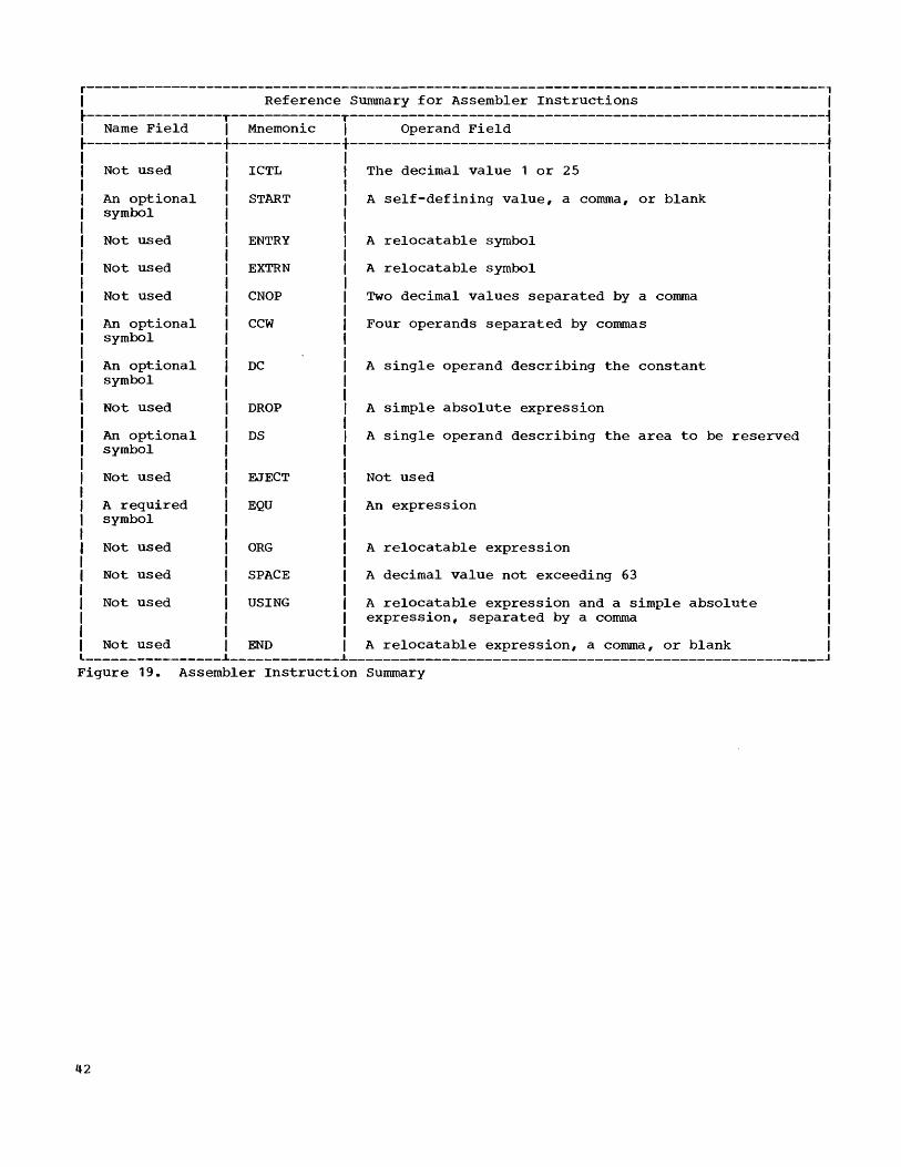
r---------------------------------------------------------------------------------------, I Reference Summary for Assembler Instructions I ~----------------T-------------T--------------------------------------------------------~ I Name Field I Mnemonic I Operand Field I ~----------------+-------------+--------------------------------------------------------1
Not used
An optional symbol
Not used
Not used
Not used
An optional symbol
An optional symbol
Not used
An optional symbol
Not used
A required symbol
Not used
Not used
Not used
ICTL
START
ENTRY
EXTRN
CNOP
CCW
DC
DROP
DS
EJECT
EQU
ORG
SPACE
USING
The decimal value 1 or 25
A self-defining value, a comma, or blank
A relocatable symbol
A relocatable symbol
Two decimal values separated by a comma
Four operands separated by commas
A single operand describing the constant
A simple absolute expression
A single operand describing the area to be reserved
Not used
An expression
A relocatable expression
A decimal value not exceeding 63
A relocatable expression and a simple absolute expression, separated by a comma
Not used END A relocatable expression, a comma, or blank ----------------~-------------~---------------------------------------------------------
Figure 19. Assembler Instruction Summary
42

This section describes those operations of the assembler program that have a direct bearing on preparing programs for assembly. Note that the use of the Basic Assembler is described in detail in the publication IBM SystemL360BasicProgramming Support Operating Guide, Form C28-6557.
ASSEMBLER PROCESSING
The assembler is a two-phase program. It is provided as two decks of cards, one for each phase.
Phase.1
During the first phase, the assembler produces a symbol table (subsequently described) and intermediate text for use in the second phase. When the tape option is used, the intermediate text (but not the symbol table) is placed on tape. When the IBM 1442-2 Card Read-Punch is used in a card-option system, this intermediate text is punched into the first 24 columns of each source program card. Because the intermediate te~t punched into the source card is still symbolic and pertains to the statement portion of the particular card only, the source program can be reassembled without being repunched. When the IBM 1402 Card Read-Punch is used in a card option system, this intermediate text is punched into the first 2'4 columns of a new card along with the first 47 columns of the source statement, column 72, and the Identification-Sequence Field (columns 73-80) • If Phase 1 is successful, a 12 punch will appear in the first column of every card containing intermediate text.
The input to the first phase consists of the Phase 1 deck of the assembler followed by the source program. If the card option is used, blank cards must be available in the punch unit, for the symbol table.
One card will be punched for every six symbols defined in the program. The maximum number of symbols that can be defined is determined by main storage size, as explained in the section ·Symbol Table." If the assembler is operating on a machine with 8,192 storage bytes, approximately 50 blank cards will be sufficient to handle
THE BASIC ASSEMBLER PROGRAM
the maximum number of symbols allowed; for 16,384 bytes, 230 blank cards; for 32,768 bytes, 570 cards; and for 65,536 bytes, 690 cards.
The assembler produces the program listing and object program during the second phase. The format of Phase 2 input varies with the option used.
For the tape option, input is on cards and tape. The card input consists of the Phase 2 deck of the assembler. The tape input is the tape created in Phase 1. If the object program is to be produced on cards, blank cards should be provided at the approximate ratio of 10 blank cards for every 100 original source program cards. If the object program is to be placed on tape, blank cards are not required.
For card option, the second deck of the assembler is loaded followed by the repunched source program when the IBM 1442-2 Card Read-Punch is used, and by the newly punched intermediate deck when the IBM 1402 Card Read-Punch is used. If the second phase does not immediately follow the first phase, the symbol table will not be in storage. Consequently, it will be necessary to load the symbol table deck produced by Phase 1. It is placed between the assembler and source program decks. (See Figure 20.)
When the IBM 1442-2 Card Read-Punch is used, the assembler will accumulate the assembled object program in storage. When the storage area is full, and the next input card is not blank, the operator will be notified to insert blank cards in the 1442-2 Card Read-Punch for punching the object p~ogram. As each blank card is punched, it will be directed to the stacker reserved for the object deck. If a blank card is encountered when none is needed, the card will be directed to the other stacker, which is for the input cards. The remaining source cards will then be read, and the cycle repeated.
Operator intervention may be avoided, in a 1442 card system, by interleaving blank cards with the source program before starting Phase 2 (see Figure 20) at approximately the following ratios:
The Basic Assembler Program 43

AEEroximate Main Storage Ratio of Blank Cards to
Size Source Program Cards
8,192 15 blanks every 150 source cards
16,384 80 blanks every 800 source cards
32,384 200 blanks every 2000 source cards
65,536 450 blanks every 4500 source cards
*Only required when Phase 2 does nat immediately follow Phase 1.
Figure 20. Phase 2 Input for Use with IBM 1442-2 Card Read-Punch
If these ratios are observed, it should not be necessary for the operator to intervene and the time required to assemble the program will be reduced.
Blank cards may also be interleaved for Phase 1; their presence will not affect this phase of ,the assembly, except for time required to read the blank cards.
When the IBM 1402 Card Read-Punch is used, the assembler will punch an object program card as soon as one is assembled in storage.
PROGRAM LISTING
A program lis~ing (if requested) will be produced for every assembly; provided an IBM 1443 Model 2 Printer, IBM 1403 Printer, or an IBM 1052 Printer-Keyboard is available. Each statement in the source program will appear on a separate line of the listing unless the suppress option is used. If the suppress option is used, only those statements containing errors will be listed. The programmer avails himself of the suppress option by indicating to the machine operator that he does not wish a listing. More detailed information on the suppress option is contained in the description of "Configuration Cards" in the publication IBM System/360 Basic Programming Support Operating Guide for Basic Assembler-and Ut~lities, Form C28-6557.
44
The program listing will consist of five fields, arranged from left to right, as follows.
Flags: This field (print positions 1-10) will contain, left-justified, a flag(s) to signal possible errors in the statement. Each flag will be represented by a single alphabetic character. See the topic -Error Notification."
Location Counter: This field (print positions 12-17) will contain the Location Counter value (in hexadecimal) assigned to the statement.
Assembled Output: This field (print positions 20-39) will contain the hexadecimal representation of the binary digits generated from the statement.
Source Statement: This field (print positions 40-111) will contain a column-forcolumn reproduction of the contents of the source statement. For the 1402 card-option, where statements begin in column 1, only columns 1-47 will be reproduced.
Identification-Sequence Field: This field (print positions 113-119) will be a repro
duction of columns 73-80 of the source card.
ERROR NOTIFICATION
The flags produced on the program listing for various source program errors are shown in the following list. Any error that causes the assembler to either a} ignore the instruction or ~ assemble zeros in the operand field of the instruction will halt further evaluation of the instruction for other errors. Therefore, when correcting such an error, the user is advised to check for any other errors in the instruction.
Flag * A * B
* C * E * F
* G I
* J K
* L * M
Cause Expression not simply relocatable. START, EXTRN, ENTRY or ICTL out of order. Location counter overflow. More than 14 EXTRNs. Operand field format error or selfdefining value in operand field too large. DC, 0, or E range error. Expression can not be mapped into base and displacement. Symbol table full. Relocation list dictionary buffer table full. Name field error. Multiple defined symbol.

* N
* 0 R
* S * T
U
* V
W
x * y * Z
Statement not used. This flag is normally accompanied by other flags which define the reason the statement was not used. If it appears alone, it indicates that the statement was completely extraneous. If the flag (N) appears by itself when using a 1442 card option system, it indicates that the source statement has been modified since a previous assembly but the intermediate text field (columns 1-24) has not been left blank. See section nReassembly Procedure." Invalid OP code. Expression not absolute. Specification error. Value too large. Undefined symbol. ORG or EQU symbol not previously defined. Unused mask bits (37-39) in CCW not zero. Duplicate entry statement. Negative expression. Column 72 not blank.
Note: The * indicates those flags which may be punched in the intermediate text cards produced by Phase 1 in card-option systems. For systems without the ability to produce program listings, these flags provide a limited form of error notification. It should be noted that the intermediate text cards produced by Phase 1 contain an A, B, or C in column 1 if they are error free. Cards in error have a J, K, L, or M in column 1. Error flags are located in columns 23-24 on cards with a J or K in column 1. The error flags appear in columns 21-24 on cards beginning with L or M.
OBJECT PROGRAM OUTPUT
The object program is generated by the assembler as a deck of cards or card images on tape acceptable as input to the loaders. It is the programmer's responsibility, to inform the operator about the medium (cards or tape) on which the obj'ect deck is to be placed. Detailed information on this option can be found in the publication IBM System/360 Basic Programming Support opei= atingGuide, Form C28-6557. Four types of cards constitute the object program deck. It should be noted that detailed descriptions of each of the four types of cards may be found in the publication IBM System/360 Basic .Programming Support Basic Utilities, Form C28-6505. General descriptions of each follow.
External Symbol Dictionary (ESD) Card
An ESD card is generated for each START, ENTR~, and EXTRN statement. The ESD card contains coded information that is used by the relocating loader.
Text (TXT) Card
The Text cards contain the output assembled from the source program. Up to 56 contiguous bytes of output are punched into each Text card. Each Text card also contains the storage address at which the first byte in the card is to be loaded.
Relocation List Dictionary (RLD) Card
The purpose of RLD cards is to indicate to the relocating loader those address constants that will have to be changed if the program is loaded at a location different from its assembled location. Address constants of this type are defined in the source program by (1) relocatable expressions in type A DC statements and (2) relocatable expressions specifying data addresses in CCW statements; that is, the second operands of CCW statements. Up to 13 address constants are punched into each RID card.
The maximum number of address constants (that is, the type described above) that can be defined in a program is determined by the size of main storage thus:
Main Storage Size (in Bytes)
8,192 16,384 32,768 65,536
Load End Card
Maximum Number of Address Constants
30 60
120 240
This card is produced when the assembler encounters the END statement. The Load End card also contains the address to which control is to be transferred when the program has been loaded, if one was specified in the END statement.
The'Basic Assembler Program 45
PATCHING OBJECT PROGRAMS
The programmer may modify his object program at execution time through the use of a Replace card. This card is completely described in the publication IBM System/360 Basic Programming Support Basic Utilities, Form C28-6505.
REASSEMBLY PROCEDURE
A special reassembly procedure is provided for assemblies using the IBM 1442-2 Card Read-Punch without tape. This procedure will enable a partially or completely assembled program to be reassembled in less time than a new assembly would require.
The program 1:hat is to use the reassembly procedure may be changed.in any manner. New symbols can be added and existing ones redefined, provided that the symbol table is not full. New statements also can be included in the program.
The reassembly procedure is faster than the new assembly procedure because the assembler does not have to repunch the first 24 columns of those source program cards whose statements have not been changed. Hence, the fewer the changes, the faster the assembly.
The input to the first phase of a reassembly consists of the first deck of the assembler, followed in order by the previously punched symbol table decks, the source program with any changes, and the necessary number of blank cards into which a new symbol table will be punched. Note that any changed source program cards must be repunched, leaving columns 1-24 blank. This also applies to source program cards that did not have a 12-punch in column 1 as the result of the previous assembly.
The Phase 2 input and output of a reassembly is identical with the second phase of a new assembly (see topic "Phase 2") •
SYMBOL TABLE
For every program assembled, a table is created of the symbols in that program. This is the symbol table; each entry in the table records the attributes and other pertinent information about a particular symbol.
46
The maximum size of the symbol table and, hence, the maximum number of symbols that can be defined in a program is determined by the size of main storage, thus:
Approximate Main Storage Size
(in ByteS)
8,192 16,384 32,768 65,536
Approximate Number of Symbols in Table
275 1299 3347 4094
All symbols defined in a program (including the program name and external
symbols) are entered in the symbol table providing the following conditions are met:
1. The symbol table is not full. 2. The symbol conforms to the rules gov
erning symbol specifications (see the topic "Symbols") •
3. The symbol does not appear in the name field of an assembler instruction that does not allow the specification of a name. See Figure 19 for a list of these instructions.
4. The symbol is not already contained in the symbol table. For multiple defined symbols, only the first definition of the symbol results in an entry in the symbol table. Additional definitions of the same symbol are simply flagged.
Any reference in the operand field to a symbol not in the symbol table will be considered undefined; the statement will be flagged. An undefined symbol in a machine instruction statement will cause the entire instruction (except the operation code) to be set to zero.
Symbol Table OVerflow
If there are undefined symbols because the symbol table is full, three corrective procedures are available:
1. The assembled object deck produced by the assembler can be corrected with Replace (RE~ cards before loading the program. Replace cards, a feature of the loaders, are used to alter an object deck on a byte-for-byte basis.
2. Reduce the number of symbols and then reassemble or run a new assembly.
3. Divide the program into segments and assemble each program segment separately.
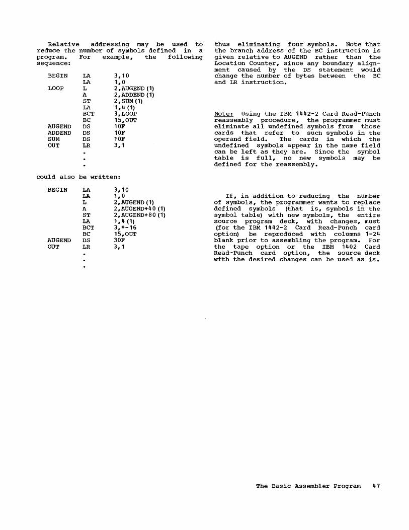
Relative addressing may be used to reduce the number of symbols defined in a program. For example, the following sequence:
BEGIN
LOOP
AUGEND ADDEND SUM OUT
LA LA L A ST LA BCT BC DS DS DS LR
3,10 1,0 2 ,AUGEND (1) 2, ADDEND (1) 2 ,SUM (1) 1,4 (1) 3,LOOP 15,OUT 10F 10F 10F 3,1
could also be written:
BEGIN
AUGEND OUT
LA LA L A ST LA BCT BC DS LR
3,10 1,0 2, AUGEND (1) 2,AUGEND+40 (1) 2,AUGEND+80 (1) 1,4 (1) 3,*-16 15,OUT 30F 3,1
thus eliminating four symbols. Note that the branch address of the BC instruction is given relative to AUGEND rather than the Location Counter, since any boundary alignment caused by the DS statement would change the number of bytes between the BC and LR instruction.
Note~ Using the IBM 1442-2 Card Read-Punch reassembly procedure, the programmer must eliminate all undefined symbols from those cards that refer to such symbols in the operand field. The cards in which the undefined symbols appear in the name field can be left as they are. Since the symbol table is full, no new symbols may be defined for the reassembly.
If, in addition to reducing the number of symbols, the programmer wants to replace defined symbols (that is, symbols in the symbol table) with new symbols, the entire s.ource program deck, wi th changes, must (for the IBM 1442-2 Card Read-Punch card
option) be reproduced with columns 1-24 blank prior to assembling the program. For the tape option or the IBM 1402 Card Read-Punch card option, the source deck wfth the desired changes can be used as is.
The Basic Assembler Program 47

APPENDIX A. CHARACTER CODES
r------------T-----------------T---------T---------T------------1 I 8-Bit I Character Set I I I II I BCD I Punch I I Hexa- I Printer I I Code I Combination I Decimal I Decimal I Graphics I ~------------+-----------------+---------+---------+------------~
00000000 12,0,9,8,1 0 00 00000001 12,9,1 1 01 00000010 12,9,2 2 02 00000011 12,9,3 3 03 00000100 12,9,4 4 04 00000101 12,9,5 5 05 00000110 12,9,6 6 06 00000111 12,9,7 7 07 00001000 12,9,8 8 08 00001001 12,9,8,1 9 09 00001010 12,9,8,2 10 OA 00001011 12,9,8,3 11 OB 00001100 12,9,8,4 12 OC 00001101 12,9,8,5 13 OD 00001110 12,9,8,6 14 OE 00001111 12,9,8,7 15 OF 00010000 12,11,9,8,1 16 10 00010001 11,9,1 17 11 00010010 11,9,2 18 12 00010011 11,9,3 19 13 00010100 11,9,4 20 14 00010101 11,9,5 21 15 00010110 11,9,6 22 16 00010111 11,9,7 23 17 00011000 11,9,8 24 18 00011001 11,9,8,1 25 19 00011010 11,9,8,2 26 1A 00011011 11,9,8,3 27 1B 00011100 11,9,8,4 28 1C 00011101 11,9,8,5 29 1D 00011110 11,9,8,6 30 1E 00011111 11,9,8,7 31 1F 00100000 11,0,9,8,1 32 20 00100001 0,9,1 33 21 00100010 0,9,2 34 22 00100011 0,9,3 35 23 00100100 0,9,4 36 24 00100101 0,9,5 37 25 00100110 0,9,6 38 26 00100111 0,9,7 39 27 00101000 0,9,8 40 28 00101001 0,9,8,1 41 29 00101010 0,9,8,2 42 2A 00101011 0,9,8,3 43 2B 00101100 0,9,8,4 44 2C 00101101 0,9,8,5 45 2D 00101110 0,9,8,6 46 2E 00101111 0,9,8,7 47 2F 00110000 12,11,0,9,8,1 48 30 00110001 9,1 49 31 00110010 9,2 50 32
____________ .J. _________________ ._.J. _________ .J. _________ J. ___________ _
48

r------------T-----------------T---------T---------T------------, I 8-Bit I Character Set I , , , , BCD I Punch , , Hexa- ,Printer , ,Code ,Combination, Decimal , Decimal ,Graphics I ~------------+-----------------+---------+---------+------------~
00110011 9,3 51 33 00110100 9,4 52 34 00110101 9,5 53 35 00110110 9,6 54 36 00110111 9,7 55 37 00111000 9,8 56 38 00111001 9,8,1 57 39 00111010 9,8,2 58 3A 00111011 9,8,3 59 3B 00111100 9,8,4 60 3C 00111101 9,8,5 61 3D 00111110 9,8,6 62 3E 00111111 9,8,7 63 3F 01000000 64 40 blank 01000001 12,0,9,1 65 41 01000010 12,0,9,2 66 42 01000011 12,0,9,3 67 43 01000100 12,0,9,4 68 44 01000101 12,0,9,5 69 45 01000110 12,0,9,6 70 46 01000111 12,0,9,7 71 47 01001000 12,0,9,8 72 48 01001001 12,8,1 73 49 01001010 12,8,2 74 4A 01001011 12,8,3 75 4B • (period) 01001100 12,8,4 76 4C < 01001101 12,8,5 77 40 { 01001110 12,8,6 78 4E + 01001111 12,8,7 79 4F 01010000 12 80 50 , 01010001 12,11,9,1 81 51 01010010 12,11,9,2 82 52 01010011 12,11,9,3 83 53 01010100 12,11,9,4 84 54 01010101 12,11,9,5 85 55 01010110 12,11,9,6 86 56 01010111 12,11,9,7 87 57 01011000 12,11,9,8 88 58 01011001 11,8,1 89 59 01011010 11,8,2 90 5A 01011011 11,8,3 91 5B $ 01011100 11,8,4 92 5C * 01011101 11,8,5 93 50 01011110 11,8,6 94 5E 01011111 11,8,7 95 5F 01100000 11 96 60 01100001 0,1 97 61 / 01100010 11,0,9,2 98 62 01100011 11,0,9,3 99 63 01100100 11,0,9,4 100 64 01100101 11,0,9,5 101 65 01100110 11,0,9,6 102 66 01100111 11,0,9,7 103 67 01101000 11,0,9,8 104 68 01101001 0,8,1 105 69 01101010 12,11 106 6A 01101011 0,8,3 107 6B , (comma) ____________ ~ _________________ ~ _________ ~ _________ ~ ____________ J
Appendix A 49

r------------T-----------------T---------T---------T------------, I 8-Bit I Character Set I I I I I BCD I Punch I I Hexa- I Printer I I Code I Combination I Decimal I Decimal I Graphics I
~------------+-----------------+---------+---------+------------~ 01101100 0,8,4 108 6C % 01101101 0,8,5 109 6D 01101110 0,8,6 110 6E 01101111 0,8,7 111 6F 01110000 12,11,0 112 70 01110001 12,11,0,9,1 113 71 01110010 12,11,0,9,2 114 72 01110011 12,11,0,9,3 115 73 01110100 12,11,0,9,4 116 74 01110101 12,11,0,9,5 117 75 01110110 12,11,0,9,6 118 76 01110111 12,11,0,9,7 119 77 01111000 12,11,0,9,8 120 78 01111001 8,1 121 79 01111010 8,2 122 7A 01111011 8,3 123 7B # 01111100 8,4 124 7C ru 01111101 8,5 125 7D • (quote) 01111110 8,6 126 7E 01111111 8,7 127 7F 10000000 12,0,8,1 128 80 10000001 12,0,1 129 81 10000010 12,0,2 130 82 10000011 12,0,3 131 83 10000100 12,0,4 132 84 10000101 12,0,5 133 85 10000110 12,0,6 134 86 10000111 12,0,7 135 87 10001000 12,0,8 136 88 10001001 12,0,9 137 89 10001010 12,0,8,2 138 8A 10001011 12,0,8,3 139 8B 10001100 12,0,8,4 140 8C 10001101 12,0,8,5 141 8D 10001110 12,0,8,6 142 8E 10001111 12,0,8,7 143 8F 10010000 12,11,8,1 144 90 10010001 12,11,1 145 91 10010010 12,11,2 146 92 10010011 12,11,3 147 93 10010100 12,11,4 148 94 10010101 12,11,5 149 95 10010110 12,11,6 150 96 10010111 12,11,7 151 97 10011000 12,11,8 152 98 10011001 12,11,9 153 99 10011010 12,11,8,2 154 9A 10011011 12,11,8,3 155 9B 10011100 12,11,8,4 156 9C 10011101 12,11,8,5 157 9D 10011110 12,11,8,6 158 9E 10011111 12,11,8,7 159 9F 10100000 11,0,8,1 160 AO 10100001 11,0,1 161 Al 10100010 11,0,2 162 A2 10100011 11,0,3 163 A3 10100100 11,0,4 164 A4 ____________ ~ _________________ ~ _________ ~ _________ ~ ____________ J
50
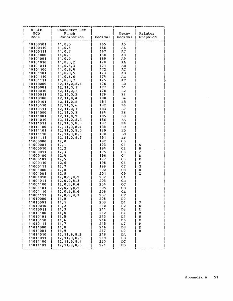
r------------T-----------------T---------T---------T------------, I 8-Bit I Character Set I I I I I BCD I Punch I I Hexa- I Printer I I Code I Combination I Decimal I Decimal I Graphics I
~------------+-----------------+---------+---------+------------~ 10100101 11,0,5 165 A5 I 10100110 11,0,6 166 A6 I 10100111 11,0,7 167 A7 I 10101000 11,0,8 168 A8 I 10101001 11,0,9 169 A9 I 10101010 11,0,8,2 170 AA I 10101011 11,0,8,3 171 AB I 10101100 11,0,8,4 172 AC I 10101101 11,0,8,5 173 AD I 10101110 11,0,8,6 174 AE I 10101111 11,0,8,7 175 AF 10110000 12,11,0,8,1 176 BO 10110001 12,11,0,1 177 Bl 10110010 12,11,0,2 178 B2 10110011 12,11,0,3 179 B3 10110100 12,11,0,4 180 B4 10110101 12,11,0,5 181 B5 10110110 12,11,0,6 182 B6 10110111 12,11,0,7 183 B7 10111000 12,11,0,8 184 B8 10111001 12,11,0,9 185 B9 10111010 12,11,0,8,2 186 BA 10111011 12,11,0,8,3 187 BB 10111100 12,11,0,8,4 188 BC 10111101 12,11,0,8,5 189 BD 10111110 12,11,0,8,6 190 BE I
10111111 12,11,0,8,7 191 BF 11000000 12,0 192 CO 11000001 12,1 193 Cl A 11000010 12,2 194 C2 B 11000011 12,3 195 C3 C 11000100 12,4 196 C4 D 11000101 12,5 197 C5 E 11000110 12,6 198 C6 F 11000111 12,7 199 C7 G 11001000 12,8 200 C8 H 11001001 12,9 201 C9 I 11001010 12,0,9,8,2 202 CA 11001011 12,0,9,8,3 203 CB 11001100 12,0,9,8,4 204 CC 11001101 12,0,9,8,5 205 CD 11001110 12,0,9,8,6 206 CE 11001111 12,0,9,8,7 207 CF 11010000 11,0 208 DO 11010001 11,1 209 Dl J 11010010 11,2 210 D2 K 11010011 11,3 211 D3 L 11010100 11,4 212 D4 M 11010101 11,5 213 D5 N 11010110 11,6 214 D6 0 11010111 11,7 215 D7 P 11011000 11,8 216 D8 Q 11011001 11,9 217 D9 R 11011010 12,11,9,8,2 218 DA 11011011 12,11,9,8,3 219 DB 11011100 12,11,9,8,4 220 DC 11011101 12,11,9,8,5 221 DD
------------~-----------------~---------~---------~------------
Appendix A 51
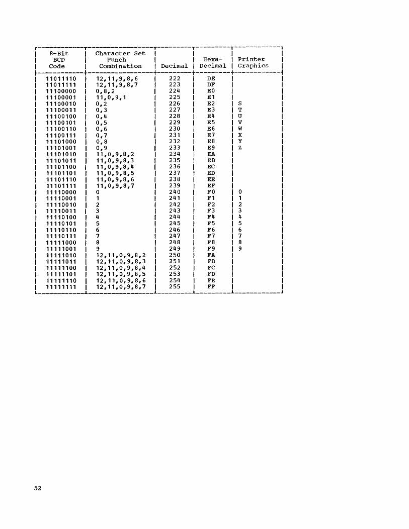
r------------T-----------------T---------T---------T------------, I 8-Bit I Character Set I I I I I BCD I Punch I I Hexa- I Printer I I Code I Combination I Decimal I Decimal I Graphics I ~------------+-----------------+---------+---------+------------~
11011110 12,11,9,8,6 222 DE 11011111 12,11,9,8,7 223 DF 11100000 0,8,2 224 EO 11100001 11,0,9,1 225 E1 11100010 0,2 226 E2 S 11100011 0,3 227 E3 T 11100100 0,4 228 E4 U 11100101 0,5 229 E5 V 11100110 0,6 230 E6 W 11100111 0,7 231 E7 X 11101000 0,8 232 E8 Y 11101001 0,9 233 E9 Z 11101010 11,0,9,8,2 234 EA 11101011 11,0,9,8,3 235 EB 11101100 11,0,9,8,4 236 EC 11101101 11,0,9,8,5 237 ED 11101110 11,0,9,8,6 238 EE 11101111 11,0,9,8,7 239 EF 11110000 0 240 FO 0 11110001 1 241 F1 1 11110010 2 242 F2 2 11110011 3 243 F3 3 11110100 4 244 F4 4 11110101 5 245 F5 5 11110110 6 246 F6 6 11110111 7 247 F7 7 11111000 8 248 F8 8 11111001 9 249 F9 9 11111010 12,11,0,9,8,2 250 FA 11111011 12,11,0,9,8,3 251 FB 11111100 12,11,0,9,8,4 252 FC 11111101 12,11,0,9,8,5 253 FD 11111110 12,11,0,9,8,6 254 FE 11111111 12,11,0,9,8,7 255 FF ____________ ~ __________________ ~ _________ ~ _________ ~ ____________ J
52

APPENDIX B. HEXADECIMAL-TO-DECIMAL CONVERSION
The table in this appendix provides for direct conversion of decimal and hexadecimal numbers in these ranges:
Hexadecimal Decimal
000 to FFF 0000 to 4095
For numbers table, add the table figures:
outside the range of the following values to the
0 1 2 3 4 5 6 7
000 0000 0001 0002 0003 0004 0005 0006 0007 010 0016 0017 0018 0019 0020 0021 0022 0023 020 0032 0033 0034 0035 0036 0037 0038 0039 030 0048 0049 0050 0051 0052 0053 0054 0055
040 0064 0065 0066 0067 0068 0069 0070 0071 050 0080 0081 0082 0083 0084 0085 0086 0087 060 0096 0097 0098 0099 0100 0101 0102 0103 070 0112 0113 0114 0115 0116 0117 0118 0119
080 0128 0129 0130 0131 0132 0133 0134 0135 090 0144 0145 0146 0147 0148 0149 0150 0151 OAO 0160 0161 0162 0163 0164 0165 0166 0167 OBO 0176 0177 0178 0179 0180 0181 0182 0183
OCO 0192 0193 0194 0195 0196 0197 0198 0199 ODO 0208 0209 0210 0211 0212 0213 0214 0215 OEO 0224 0225 0226 0227 0228 0229 0230 0231 OFO 0240 0241 0242 0243 0244 0245 0246 0247
100 0256 0257 0258 0259 0260 0261 0262 0263 110 0272 0273 0274 0275 0276 0277 0278 0279 120 0288 0289 0290 0291 0292 0293 0294 0295 130 0304 0305 0306 0307 0308 0309 0310 0311
140 0320 0321 0322 0323 0324 0325 0326 0327 150 0336 0337 0338 0339 0340 0341 0342 0343 160 0352 0353 0354 0355 0356 0357 0358 0359 170 0368 0369 0370 0371 0372 0373 0374 0375
180 0384 0385 0386 0387 0388 0389 0390 0391 190 0400 0401 0402 0403 0404 0405 0406 0407 lAO 0416 0417 0418 0419 0420 0421 0422 0423 1BO 0432 0433 0434 0435 0436 0437 0438 0439
1CO 0448 0449 0450 0451 0452 0453 0454 0455 1DO 0464 0465 0466 0467 0468 0469 0470 0471 lEO 0480 0481 0482 0483 0484 0485 0486 0487 1FO 0496 0497 0498 0499 0500 0501 0502 0503
8
0008 0024 0040 0056
0072 0088 0104 0120
0136 0152 0168 0184
0200 0216 0232 0248
0264 0280 0296 0312
0328 0344 0360 0376
0392 0408 0424 0440
0456 0472 0488 0504
Hexadecimal
1000 2000 3000 4000 5000 6000 7000 8000 9000 AOOO BOOO COOO DOOO EOOO FOOO
9 A
0009 0010 0025 0026 0041 0042 0057 0058
0073 0074 0089 0090 0105 0106 0121 0122
0137 0138 0153 0154 0169 0170 0185 0186
0201 0202 0217 0218 0233 0234 0249 0250
0265 0266 0281 0282 0297 0298 0313 0314
0329 0330 0345 0346 0361 0362 0377 0378
0393 0394 0409 0410 0425 0426 0441 0442
0457 0458 0473 0474 0489 0490 0505 0506
B
0011 0027 0043 0059
0075 0091 0107 0123
0139 0155 0171 0187
0203 0219 0235 0251
0267 0283 0299 0315
0331 9347 0363 0379
0395 0411 0427 0443
0459 0475 0491 0507
4096 8192
12288 16384 20480 24576 28672 32768 36864 40960 45056 49152 53248 57344 61440
C D
0012 0013 0028 0029 0044 0045 0060 0061
0076 0077 0092 0093 0108 0109 0124 0125
0140 0141 0156 0157 0172 0173 0188 0189
0204 0205 0220 0221 0236 0237 0252 0253
0268 0269 0284 0285 0300 0301 0316 0317
0332 0333 0348 0349 0364 0365 0380 0381
0396 0397 0412 0413 0428 0429 0444 0445
0460 0461 0476 0477 0492 0493 0508 0509
E F
0014 0015 0030 0031 0046 0047 0062 0063
0078 0079 0094 0095 0110 0111 0126 0127
0142 0143 0158 0159 0174 0175 0190 0191
0206 0207 0222 0223 0238 0239 0254 0255
0270 0271 0286 0287 0302 0303 0318 0319
0334 0335 0350 0351 0366 0367 0382 0383
0398 0399 0414 0415 0430 0431 0446 0447
0462 0463 0478 0479 0494 0495 0510 0511
Appendix B 53

200 210 220 230
240 250 260 270
280 290 ZAO 2BO
2CO 2DO 2EO 2FO
300 310 320 330
340 350 360 370
380 390 3AO 3BO
3CO 3DO 3EO 3FO
400 410 420 430
440 450 460 470
480 490 4AO 4BO
4CO 4DO 4EO 4FO
500 510 520 530
540 550 560 570
580 590 5AO 5BO
5CO 5DO 5EO 5FO
54
o
0512 0528 0544 0560
0576 0592 0608 0624
0640 0656 0672 0688
0704 0720 0736 0752
0768 0784 0800 0816
0832 0848 0864 0880
0896 0912 0928 0944
0960 0976 0992 1008
o
1024 1040 1056 1072
1088 1104 1120 1136
1152 1168 1184 1200
1216 1232 1248 1264
1280 1296 1312 1328
1344 1360 1376 1392
1408 1424 1440 1456
1472 1488 1504 1520
1
0513 0529 0545 0561
0577 0593 0609 0625
0641 0657 0673 0689
0705 0721 0737 0753
0769 0785 0801 0817
0833 0849 0865 0881
0897 0913 0929 0945
0961 0977 0993 1009
1025 1041 1057 1073
1089 1105 1121 1137
1153 1169 1185 1201
1217 1233 1249 1265
1281 1297 1313 1329
1345 1361 1377 1393
1409 1425 1441 1457
1473 1489 1505 1521
2
0514 0530 0546 0562
0578 0594 0610 0626
0642 0658 0674 0690
0706 0722 0738 0754
0770 0786 0802 0818
0834 0850 0866 0882
0898 0914 0930 0946
0962 0978 0994 1010
2
1026 1042 1058 1074
1090 1106 1122 1138
1154 1170 1186 1202
1218 1234 1250 1266
1282 1298 1314 1330
1346 1362 1378 1394
1410 1426 1442 1458
1474 1490 1506 1522
3
0515 0531 0547 0563
0579 0595 0611 0627
0643 0659 0675 0691
0707 0723 0739 0755
0771 0787 0803 0819
0835 0851 0867 0883
0899 0915 0931 0947
0963 0979 0995 1011
3
1027 1043 1059 1075
1091 1107 1123 1139
1155 1171 1187 1203
1219 1235 1251 1267
1283 1299 1315 1331
1347 1363 1379 1395
1411 1427 1443 1459
1475 1491 1507 1523
4
0516 0532 0548 0564
0580 0596 0612 0628
0644 0660 0676 0692
0708 0724' 0740 0756
0772 0788 0804 0820
0836 0852 0868 0884
0900 0916 0932 0948
0964 0980 0996 1012
4
1028 1044 1060 1076
1092 1108 1124 1140
1156 1172 1188 1204
1220 1236 1252 1268
1284 1300 1316 1332
1348 1364 1380 1396
1412 1428 1444 1460
1476 1492 1508 1524
5
0517 0533 0549 0565
0581 0597 0613 0629
0645 0661 0677 0693
0709 0725 0741 0757
0773 0789 0805 0821
0837 0853 0869 0885
0901 0917 0933 0949
0965 0981 0997 1013
5
1029 1045 1061 1077
1093 1109 1125 1141
1157 1173 1189 1205
1221 1237 1253 1269
1285 1301 1317 1333
1349 1365 1381 1397
1413 1429 1445 1461
1477 1493 1509 1525
6
0518 0534 0550 0566
0582 0598 0614 0630
0646 0662 0678 0694
0710 0726 0742 0758
0774 0790 0806 0822
0838 0854 0870 0886
0902 0918 0934 0950
0966 0982 0998 1014
6
1030 1046 1062 1078
1094 1110 1126 1142
1158 1174 1190 1206
1222 1238 1254 1270
1286 1302 1318 1334
1350 1366 1382 1398
1414 1430 1446 1462
1478 1494 1510 1526
7
0519 0535 0551 0567
0583 0599 0615 0631
0647 0663 0679 0695
0711 0727 0743 0759
0775 0791 0807 0823
0839 0855 0871 0887
0903 0919 0935 0951
0967 0983 0999 1015
7
1031 1047 1063 1079
1095 1111 1127 1143
1159 1175 1191 1207
1223 1239 1255 1271
1287 1303 1319 1335
1351 1367 1383 1399
1415 1431 1447 1463
1479 1495 1511 1527
8
0520 0536 0552 0568
0584 0600 0616 0632
0648 0664 0680 0696
0712 0728 0744 0760
0776 0792 0808 0824
0840 0856 0872 0888
0904 0920 0936 0952
0968 0984 1000 1016
8
1032 1048 1064 1080
1096 1112 1128 1144
1160 1176 1192 1208
1224 1240 1256 1272
1288 1304 1320 1336
1352 1368 1384 1400
1416 1432 1448 1464
1480 1496 1512 1528
9
0521 0537 0553 0569
0585 0601 0617 0633
0649 0665 0681 0697
0713 0729 0745 0761
0777 0793 0809 0825
0841 0857 0873 0889
0905 0921 0937 0953
0969 0985 1001 1017
9
1033 1049 1065 1081
1097 1113 1129 1145
1161 1177 1193 1209
1225 1241 1257 1273
1289 1305 1321 1337
1353 1369 1385 1401
1417 1433 1449 1465
1481 1497 1513 1529
A
0522 0538 0554 0570
0586 0602 0618 0634
0650 0666 0682 0698
0714 0730 0746 0762
0778 0794 0810 0826
0842 0858 0874 0890
0906 0922 0938 0954
0970 0986 1002 1018
A
1034 1050 1066 1082
1098 1114 1130 1146
1162 1178 1194 1210
1226 1242 1258 1274
1290 1306 1322 1338
1354 1370 1386 1402
1418 1434 1450 1466
1482 1498 1514 1530
B
0523 0539 0555 0571
0587 0603 0619 0635
0651 0667 0683 0699
0715 0731 0747 0763
0779 0795 0811 0827
0843 0859 0875 0891
0907 0923 0939 0955
0971 0987 1003 1019
B
1035 1051 1067 1083
1099 1115 1131 1147
1163 1179 1195 1211
1227 1243 1259 1275
1291 1307 1323 1339
1355 1371 1387 1403
1419 1435 1451 1467
1483 1499 1515 1531
C
0524 0540 0556 0572
0588 0604 0620 0636
0652 0668 0684 0700
0716 0732 0748 0764
0780 0796 0812 0828
0844 0860 0876 0892
0908 0924 0940 0956
0972 0988 1004 1020
C
1036 1052 1068 1084
1100 1116 1132 1148
1164 1180 1196 1212
1228 1244 1260 1276
1292 1308 1324 1340
1356 1372 1388 1404
1420 1436 1452 1468
1484 1500 1516 1532
D
0525 0541 0557 0573
0589 0605 0621 0637
0653 0669 0685 0701
0717 0733 0749 0765
0781 0797 0813 0829
0845 0861 0877 0893
0909 0925 0941 0957
0973 0989 1005 1021
D
1037 1053 1069 1085
1101 1117 1133 1149
1165 1181 1197 1213
1229 1245 1261 1277
1293 1309 1325 1341
1357 1373 1389 1405
1421 1437 1453 1469
1485 1501 1517 1533
E
05215 0542 0558 0574
0590 0606 0622 0636
065/. 0670 0686 0702
0716 0734 0750 0761>
0782 0796 0814 0830
0846 0862 0876 0894
0910 092t> 0942 0956
097~.
0990 1006 1022
E
1038 1054 1070 1086
1102 11 HI 1134 1150
1166 1182 1198 1214
1230 1246 1262. 1278
1294 1310 1326 1342.
1358 1374 1390 1406
1422 1438 1454 1470
1486 1502 1518 1534
F
0527 0543 0559 0575
0591 0607 0623 0639
0655 0671 0687 0703
0719 0735 0751 0767
0783 0799 0815 0831
0847 0863 0879 0895
0911 0927 0943 0959
0975 0991 1007 1023
F
1039 1055 1071 1087
1103 1119 1135 1151
1167 1183 1199 1215
1231 1247 1263 1279
1295 1311 1327 1343
1359 1375 1391 1407
1423 1439 1455 1471
1487 1503 1519 1535

600 610 620 630
640 650 660 670
680 690 6AO 6BO
6CO 6DO 6EO 6FO
700 710 720 730
740 750 760 770
780 790 7AO 7BO
7CO 7DO 7EO 7FO
800 810 820 830
840 850 860 870
880 890 8AO 8BO
8CO 8DO 8EO 8FO
900 910 920 930
940 950 960 970
980 990 gAO 9BO
9CO 9DO 9EO 9FO
o
1536 1552 1568 1584
1600 1616 1632 1648
1664 1680 1696 1712
1728 1744 1760 1776
1792 1808 1824 1840
1856 1872 1888 1904
1920 1936 1952 1968
1984 2000 2016 2032
o
2048 2064 2080 2096
2112 2128 2144 2160
2176 2192 2208 2224
2240 2256 2272 2288
2304 2320 2336 2352
2368 2384 2400 2416
2432 2448 2464 2480
2496 2512 2528 2544
1537 1553 1569 1585
1601 1.617 1633 1649
1665 1681 1697 1713
1729 1745 1761 1777
1793 1809 1825 1841
1857 1873 1889 1905
1921 1937 1953 1969
1985 2001 2017 2033
2049 2065 2081 2097
2113 2129 2145 2161
2177 2193 2209 2225
2241 2257 2273 2289
2305 2321 2337 2353
2369 2385 2401 2417
2433 2449 2465 2481
2497 2513 2529 2545
2
1538 1554 1570 1586
1602 1618 1634 1650
1666 1682 1698 1714
1730 1746 1762 1778
1794 1810 1826 1842
1858 1874 1890 1906
1922 1938 1954 1970
1986 2002 2018 2034
2
2050 2066 2082 2098
2114 2130 2146 2162
2178 2194 2210 2226
2242 2258 2274 2290
2306 2322 2338 2354
2370 2386 2402 2418
2434 2450 2466 2482
2498 2514 2530 2546
3
1539 1555 1571 1587
1603 1619 1635 1651
1667 1683 1699 1715
1731 1747 1763 1779
1795 1811 1827 1843
1859 1875 1891 1907
1923 1939 1955 1971
1987 2003 2019 2035
3
2051 2067 2083 2099
2115 2131 2147 2163
2179 2195 2211 2227
2243 2259 2275 2291
2307 2323 2339 2355
2371 2387 2403 2419
2435 2451 2467 2483
2499 2515 2531 2547
4
1540 1556 1572 1588
1604 1620 1636 1652
1668 1684 1700 1716
1732 1748 1764 1780
1796 1812 1828 1844
1860 1876 1892 1908
1924 1940 1956 1972
1988 2004 2020 2036
4
2052 2068 2084 2100
2116 2132 2148 2164
2180 2196 2212 2228
2244 2260 2276 2292
2308 2324 2340 2356
2372 2388 2404 2420
2436 ~452 2468 2484
2500 2516 2532 2548
5
1541 1557 1573 1589
1605 1621 1637 1653
1669 1685 1701 1717
1733 1749 1765 1781
1797 1813 1829 1845
1861 1871 1893 1909
1925 1941 1957 1973
1989 2005 2021 2037
5
2053 2069 2085 2101
2117 2133 2149 2165
2181 2197 2213 2229
2245 2261 2277 2293
2309 2325 2341 2357
2373 2389 2405 2421
2437 2453 2469 2485
2501 2517 2533 2549
6
1542 1558 1574 1590
1606 1622 1638 1654
1670 1686 1702 1718
1734 1750 1766 1782
1798 1814 1830 1846
1862 1878 1894 1910
1926 1942 1958 1974
1990 2006 2022 2038
6
2054 2070 2086 2102
2118 2134 2150 2166
2182 2198 2214 2230
2246 2262 2278 2294
2310 2326 2342 2358
2374 2390 2406 2422
2438 2454 2470 2486
2502 2518 2534 2550
7
1543 1559 1575 1591
1607 1623 1639 1655
1671 1687 1703 1719
1735 1751 1767 1783
1799 1815 1831 1847
1863 1879 1895 1911
1927 1943 1959 1975
1991 2007 2023 2039
7
2055 2071 2087 2103
2119 2135 2151 2167
2183 2199 2215 2231
2247 2263 2279 2295
2311 2327 2343 2359
2375 2391 2407 2423
2439 2455 2471 2487
2503 2519 2535 2551
8
1544 1560 1516 1592
1608 1624 1640 1656
1672 1688 1704 1720
1736 1752 1768 1784
1800 1816 1832 1848
1864 1880 1896 1912
1928 1944 1960 1976
1992 2008 2024 2040
8
2056 2072 2088 2104
2120 2136 2152 2168
2184 2200 2216 2232
2248 2264 2280 2296
2312 2328 ?344 2360
2376 2392 2408 2424
2440 2456 2472 2488
2504 2520 2536 2552
9
1545 1561 1577 1593
1609 1625 1641 1657
1673 1689 1705 1721
1737 1753 1769 1785
1801 1817 1833 1849
1865 1881 1897 1913
1929 1945 1961 1971
1993 2009 2025 2041
9
2057 2073 2089 2105
2121 2137 2153 2169
2185 2201 2217 2233
2249 2265 2281 2297
2313 2329 2345 2361
2371 2393 2409 2425
2441 2457 2473 2489
2505 2521 2537 2553
A
1546 1562 1578 1594
1610 1626 1642 1658
1674 1690 1706 1722
1738 1754 1770 1786
1802 1818 1834 1850
1866 1882 1898 1914
1930 1946 1962 1978
1994 2010 2026 2042
A
2058 2074 2090 2106
2122 2138 2154 2170
2186 2202 2218 2234
2250 2266 2282 2298
2314 2330 2346 2362
2378 2394 2410 2426
2442 2458 2474 2490
2506 2522 2538 2554
B
1547 1563 1579 1595
1611 1627 1643 1659
1675 1691 1707 1723
1739 1755 1771 1787
1803 1819 1835 1851
1867 1883 1899 1915
1931 1947 1963 1979
1995 2011 2027 2043
B
2059 2075 2091 2107
2123 2139 2155 2171
2187 2203 2219 2235
2251 2267 2283 2299
2315 2331 2347 2363
2379 2395 2411 2427
2443 2459 2475 2491
2507 2523 2539 2555
C
1548 1564 1580 1596
1612 1628 1644 1660
1676 1692 1708 1724
1740 1756 1772 1788
1804 1820 1836 1852
1868 1884 1900 1916
1932 1948 1964 1980
1996 2012 2028 2044
C
2060 2076 2092 2108
2124 2140 2156 2172
2188 2204 2220 2236
2252 2268 2284 2300
2316 2332 23.48 2364
2380 2396 2412 2428
2444 2460 2476 2492
2508 2524 2540 2556
D
1549 1565 1581 1597
1613 1629 1645 1661
1671 1693 1709 1725
1741 1757 1773 1789
1805 1821 1837 1853
1869 1885 1901 1917
1933 1949 1965 1981
1997 2013 2029 2045
D
2061 2071 2093 2109
2125 2141 2157 2173
2189 2205 2221 2237
2253 2269 2285 2301
2317 2333 2349 2365
2381 2397 2413 2429
2445 2461 2471 2493
2509 2525 2541 2557
E
1550 1566 1582 1598
1614 1630 1646 1662
1678 1694 1710 1726
1742 1758 1774 1790
1806 1822 1838 1854
1870 1886 1902 1918
1934 1950 1966 1982
1998 2014 2030 2046
E
2062 2078 2094 2110
2126 2142 2158 2174
2190 2206 2222 2238
2254 2270 2286 2302
2318 2334 2350 2366
2382 2398 2414 2430
2446 2462 2478 2494
2510 2526 2542 2558
F
1551 1567 1583 1599
1615 1631 1647 1663
1679 1695 1711 1727
1743 1759 1715 1791
1807 1823 1839 1855
1871 1887 1903 1919
1935 1951 1967 1983
1999 2015 2031 2047
F
2063 2079 2095 2111
2127 2143 2159 2175
2191 2207 2223 2239
2255 2271 2287 2303
2319 2335 2351 2367
2383 2399 2415 2431
2447 2463 2479 2495
2511 2527 2543 2559
Appendix B 55
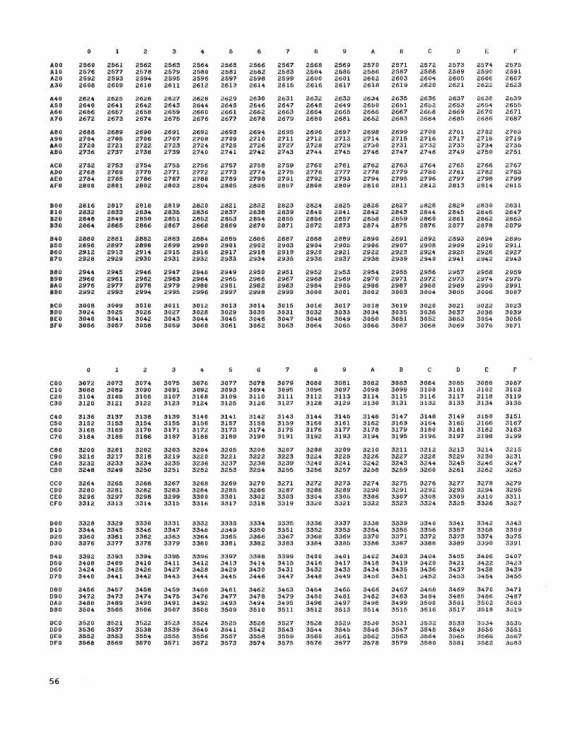
AOO A10 A20 A30
A40 A50 A60 A70
A80 A90 AAO ABO
ACO ADO AEO AFO
BOO B10 B20 B30
B40 B50 B60 B70
B80 B90 BAO BBO
BCO BDO BEO BFO
COO C10 C20 C30
C40 C50 C60 C70
C80 C90 CAO CBO
CCO CDO CEO CFO
DOO D10 D20 D30
D40 D50 D60 D70
D80 D90 DAO DBO
DCO DDO DEO DFO
56
o
2560 2576 2592 2608
2624 2640 2656 2672
2688 2704 2720 2736
2752 2768 2784 2800
2816 2832 2848 2864
2880 2896 2912 2928
2944 2960 2976 2992
3008 3024 3040 3056
o
3072 3088 3104 3120
3136 3152 3168 3184
3200 3216 3232 3248
3264 3280 3296 3312
3328 3344 3360 3376
3392 3408 3424 3440
3456 3472 3488 3504
3520 3536 3552 3568
1
2561 2577 2593 2609
2625 2641 2657 2673
2689 2705 2721 2737
2753 2769 2785 2801
2817 2833 2849 2865
28S1 2897 2913 2929
2945 2961 2977 2993
3009 3025 3041 3057
1
3073 3089 3105 3121
3137 3153 3169 3185
3201 3217 3233 3249
3265 3281 3297 3313
3329 3345 3361 3377
3393 3409 3425 3441
3457 3473 3489 3505
3521 3537 3553 3569
2
2562 2578 2594 2610
2626 2642 2658 2674
2690 2706 2722 2738
·2754 2770 2786 2802
2818 2834 2850 2866
2882 2898 2914 2930
2946 2962 2978 2994
3010 3026 3042 3058
2
3074 3090 3106 3122
3138 3.154 3170 3186
3202 3218 3234 3250
3266 3282 3298 3314
3330 3346 3362 3378
3394 3410 3426 3442
3458 3474 3490 3506
3522 3538 3554 3570
3
2563 2579 2595 2611
2627 2643 2659 2675
2691 2707 2723 2739
2755 2771 2787 2803
2819 2835 2851 2867
2883 2899 2915 2931
2947 2963 2979 2995
3011 3027 3043 3059
3
3075 3091 3107 3123
3139 3155 3171 3187
3203 3219 3235 3251
3267 3283 3299 3315
3331 3347 3363 3379
3395 3411 3427 3443
3459 3475 3491 3507
3523 3539 3555 3571
4
2564 2580 2596 2612
2628 2644 2660 2676
2692 2708 2724 2740
2756 2772 2788 2804
2820 2836 2852 2868
2884 2900 2916 2932
2948 2964 2980 2996
3012 3028 3044 3060
4
3076 3092 3108 3124
3140 3156 3172 3188
3204 3220 3236 3252
3268 3284 3300 3316
3332 3348 3364 3380
3396 3412 3428 3444
3460 3476 3492 3508
3524 3540 3556 3572
5
2565 2581 2597 2613
2629 2645 2661 2677
2693 2709 2725 2741
2757 2773 2789 2805
2821 2837 2853 2869
2885 2901 2917 2933
2949 2965 2981 2997
3013 3029 3045 3061
5
3077 3093 3109 3125
3141 3157 3173 3189
3205 3221 3237 3253
3269 3285 3301 3317
3333 3349 3365 3381
3397 3413 3429 3445
3461 3477 3493 3509
3525 3541 3557 3573
6
2566 2582 2598 2614
2630 2646 2662 2678
2694 2710 2726 2742
2758 2774 2790 2806
2822 2838 2854 2870
2886 2902 2918 2934
2950 2966 2982 2998
3014 3030 3046 3062
6
3078 3094 3110 3126
3142 3158 3174 3190
3206 3222 3238 3254
3270 3286 3302 3318
3334 3350 3366 3382
3398 3414 3430 3446
3462 3478 3494 3510
3526 3542 :1558 3574
7
2567 2583 2599 2615
2631 2647 2663 2679
2695 2711 2727 2743
2759 2775 2791 2807
2823 2839 2855 2871
2887 2903 2919 2935
2951 2967 2983 2999
3015 3031 3047 3063
7
3079 3095 3111 3127
3143 3159 3175 3191
3207 3223 3239 3255
3271 3287 3303 3319
3335 3351 3367 3383
3399 3415 3431 3447
3463 3479 3495 3511
3527 3543 3559 3575
8
2568 2584 2600 2616
2632 2648 2664 2680
2696 2712 2728 2744
2760 2776 2792 2808
2824 2640 2856 2872
2888 2904 2920 2936
2952 2968 2984 3000
3016 3032 3048 3064
8
3080 3096 3112 3128
3144 3160 3176 3192
3208 3224 3240 3256
3272 3288 3304 3320
3336 3352 3368 3384
3400 3416 3432 3448
3464 3480 3496 3512
3528 3544 3560 3576
9
2569 2585 2601 2617
2633 2649 2665 2681
2697 2713 2729 2745
2761 2777 2793 2809
2825 2841 2857 2873
2889 2905 2921 2937
2953 2969 2985 3001
3017 3033 3049 3065
9
3081 3097 3113 3129
3145 3161 3177 3193
3209 3225 3241 3257
3273 328!;! 3305 3321
3337 3353 3369 3385
3401 3417 3433 3449
3465 3481 3497 3513
3529 3545 3561 3577
A
2570 2586 2602 2618
2634 2650 2666 2682
2698 2714 2730 2746
2762 2778 2794 2810
2826 2842 2858 2874
2890 2906 2922 2938
2954 2970 2986 3002
3018 3034 3050 3066
A
3082 3098 3114 3130
3146 3162 3178 3194
3210 3226 3242 3258
3274 3290 3306 3322
3338 3354 3370 3386
3402 3418 3434 3450
3466 3482 3498 3514
3530 3546 3562 3578
B
2571 2587 2603 2619
2635 2651 2667 2683
2699 2715 2731 2747
2763 2779 2795 2811
2827 2843 2859 2875
2891 2907 2923 2939
2955 2971 2987 3003
3019 3035 3051 3067
B
3083 3099 3115 3131
3147 3163 3179 3195
3211 3227 3243 3259
3275 3291 3307 3323
3339 3355 3371 3387
3403 3419 3435 3451
3467 3483 3499 3515
3531 3547 3563 3579
c
2572 2588 2604 2620
2636 2652 2668 2684
2700 2716 2732 2748
2764 2780 2796 2812
G828 2844 2860 2876
2892 2908 2924 2940
2956 2972 2988 3004
3020 3036 3052 3068
c
3084 3100 3116 3132
3148 3164 3180 3196
3212 3228 3244 3260
3276 3292 3308 3324
3340 3356 3372 3388
3404 3420 3436 3452
3468 3484 3500 3516
3532 3548 3564 3580
D
2573 2589 2605 2621
2637 2653 2669 2685
2701 2717 2733 2749
2765 2781 2797 2813
2829 2845 2861 2877
2893 2909 2925 2941
2957 2973 2989 3005
3021 3037 3053 3069
D
3085 3101 3117 3133
3149 3165 3181 3197
3213 3229 3245 3261
3277 3293 3309 3325
3341 3357 3373 3389
3405 3421 3437 3453
3469 3485 3501 3517
3533 3549 3565 3581
E
2574 2590 2606 2622
2638 2654 2670 2686
2702 2718 2734 2750
2766 2782 2798 2814
G830 2846 2862 2878
2894 2910 2926 2942
2958 2974 2990 3006
3022 3038 3054 3070
E
3086 3102 3118 3134
3150 3166 3182 3198
3214 3230 3246 3262
3278 3294 3310 3326
3342 3358 3374 3390
;3406 3422 3438 3454
3470 3486 3502 3518
3534 3550 3566 3582
f
2575 2591 2607 2623
2639 2655 2671 2687
2703 2719 2735 2751
2767 2783 2799 2815
2831 2847 2863 2879
2895 2911 2927 2943
2959 2975 2991 3007
3023 3039 3055 3071
f
3087 3103 3119 3135
3151 3167 3183 3199
3215 3231 3G47 3263
3279 3295 3311 3327
3343 3359 3375 3391
3407 3423 3439 3455
3471 3487 3503 3519
3535 3551 3::>67 3::183

0 1 2 3 4 5 6 7 8 9 A B C D E F
EOO 3584 3585 3586 3587 3588 3589 3590 3591 3592 3593 3594 3595 3596 3597 3598 3599 E10 3600 3601 3602 3603 3604 3605 3606 3607 3608 3609 3610 3611 3612 3613 3614 3615 E20 3616 3617 3618 3619 3620 3621 3622 3623 3624 3625 3626 3627 3628 3629 3630 3631 E30 3632 3633 3634 3635 3636 3637 3638 3639 3640 3641 3642 3643 3644 3645 3646 3647
E40 3648 3649 3650 3651 3652 3653 3654 3655 3656 3657 3658 3659 3660 3~~1 3662 3663 E50 3664 3665 3666 3667 3668 3669 3670 3671 3672 3673 3674 3675 3676 36 7 3678 3679 E60 3680 3681 3682 3683 3684 3685 3686 3687 3688 3689 3690 3691 3692 3693 3694 3695 E70 3696 3697 3698 3699 3700 3701 3702 3703 3704 3705 3706 3707 3708 3709 3710 3111
E80 3712 3713 3714 3715 3716 3717 3718 3719 3720 3721 3722 3723 3724 3725 3726 3727 E90 3728 3729 3730 3731 3732 3733 3734 3735 3736 3737 3738 3739 3740 3741 3742 3743 IEAO 3744 3745 3746 3747 3748 3749 3750 3751 3752 3753 3754 3755 3756 3757 3758 3759 [BO 3760 3761 3762 3763 3764 3765 3766 3767 3768 3769 3770 3771 3772 3773 3774 3775
ECO 3776 3777 3778 3779 3780 3781 3782 3783 3784 3785 3786 3787 3788 3789 3790 3791 EDO 3792 3793 3794 3795 3796 3797 3798 3799 3800 3801 3802 3803 3804 3805 3806 3807 EEO 3808 3809 3810 3811 3812 3813 3814 3815 3816 3817 3818 3819 3820 3821 3822 3823 EFO 3824 3825 3826 3827 3828 3829 3830 3831 3832 3833 3834 3835 3836 3837 3838 3839
FOO 3840 3841 3842 3843 3844 3845 3846 3847 3848 3849 3850 3851 3852 3853 3854 3855 flO 3856 3857 3858 3859 3860 3861 3862 3863 3864 3865 3866 3867 3868 3869 3870 3871 F20 3872 3873 3874 3875 3876 3877 3878 3879 3880 3881 3882 3883 3884 3885 3886 3887 F30 3888 3889 3890 3891 3892 3893 3894 3895 3896 3897 3898 3899 3900 3901 3902 3903
F40 3904 0905 0906 0907 3908 3909 3910 3911 3912 3913 3914 3915 3916 3917 3918 3919 F50 3920 0921 0922 0923 3924 3925 3926 3927 3928 3929 3930 3931 3932 3933 3934 3935 F60 3936 0937 0938 0939 3940 3941 3942 3943 3944 3945 3946 3947 3948 3949 3950 3951 F70 3952 0953 0954 0955 3956 3957 3958 3959 3960 3961 3962 3963 3964 3965 3966 3967
F80 3968 0969 0970 0971 3972 3973 3974 3975 3976 3977 3978 3979 3980 3981 3982 3983 F90 3984 0985 0986 0987 3988 3989 3990 3991 3992 3993 3994 3995 39~6 3997 3998 3999 FAO 4000 4001 4002 4003 4004 4005 4006 4007 4008 4009 4010 4011 4012 4013 4014 4015 FBO 4016 4017 4018 4019 4020 4021 4022 4023 4024 4025 4026 4027 4028 4029 4030 4031
FCO 4032 4033 4034 4035 4036 4037 4038 4039 4040 4041 4042 4043 4044 4045 4046 4047 FDO 4048 4049 4050 4051 4052 4053 4054 4055 4056 4057 4058 4059 4060 4061 4062 4063 FEO 4064 4065 4066 4067 4068 4069 4070 4071 4072 4073 4074 4075 4076 4077 4078 4079 FFO 4080 4081 4082 4083 4084 4085 4086 4087 4088 4089 4090 4091 4092 4093 4094 4095
Appendix B 57
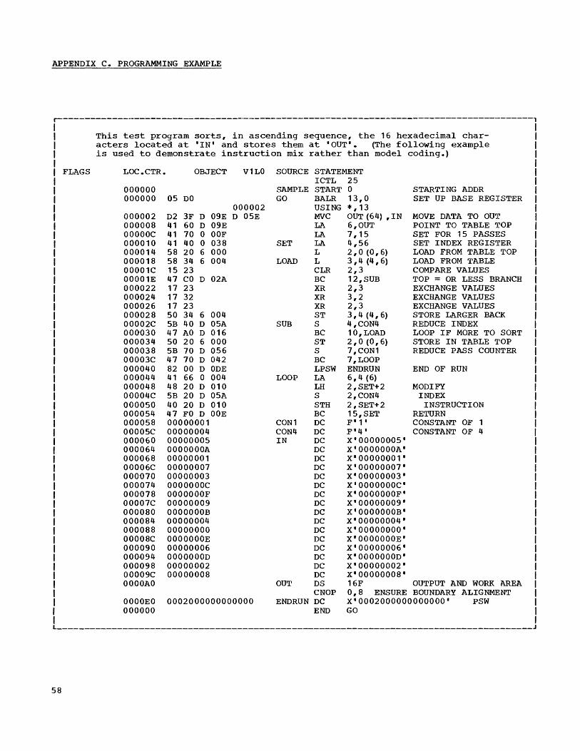
APPENDIX C. PROGRAMMING EXAMPLE
r-----------------'-----------------------------------------------------------------------,
FLAGS
This test program sorts, in ascending sequence, the 16 hexadecimal characters located at 'IN' and stores them at 'OUT'. (The following example is used to demonstrate instruction mix rather than model coding.)
LOC.CTR.
000000 000000
000002 000008 OOOOOC 000010 000014 000018 00001C 00001E 000022 000024 000026 000.028 00002C 000030 000034 000038 00003C 000040 000044 000048 00004C 000050 000054 000058 00005C 000060 000064 000068 00006C 000070 000074 000078 00007C 000080 000084 000088 00008C 000090 000{)94 000098 000.o9C OOOOAO
OOOOEO OOOQOO
OBJECT V1LO
05 DO 000002
D2 3F D 09E D 05E 41 60 D 09E 41 70 0 OOF 41 40 0 038 58 20 6 000 58 34 6 004 15 23 47 CO D 02A 17 23 17 32 17 23 50 34 6 004 5B 40 D 05A 47 AO D 016 50 20 6 000 5B 70 D 056 47 70 D 042 82 00 D ODE 41 66 0 004 48 20 D 010 5B 20 D 05A 40 20 D 010 47 FO D OOE 00000001 00000004 00000005 OOOOOOOA 00000001 00000007 00000003 OOOOOOOC OOOOOOOF 00000009 OOOOOOOB 00000004 00000000 OOOOOOOE 00000006 OOOOOOOD 00000002 00000008
0002000000000000
SOURCE STATEMENT ICTL 25
SAMPLE START 0 GO BALR 13,0
USING *,13
SET
LOAD
SUB
LOOP
CON1 CON4 IN
MVC OUT (64) ,IN LA 6,OUT LA 7,15 LA 4,56 L 2,0 (0,6) L 3,4 (4,6) CLR 2,3 BC 12,SUB XR 2,3 XR 3,2 XR 2,3 ST 3,4 (4,6) S 4,CON4 BC 10,LOAD ST 2,0 (0,6) S 7,CON1 BC 7, LOOP LPSW ENDRUN LA 6,4(6) LH 2,SET+2 S 2,CON4 STH 2,SET+2 BC 15,SET DC F'1' DC F'4' DC X'000000~5' DC X'OOOOOOOA' DC X'00000001' DC X'00000007' DC X'00000003' DC X'OOOOOOOC' DC X'OOO.oOOOF' DC X'00000009' DC X'OOOOOOOB' DC X'00000004' DC X'OOOOOOOO' DC X'OOOOOOOE' DC X'00000006' DC X'OOOOOOOD' DC X'00000002' DC X'00000008'
STARTING ADDR SET UP BASE REGISTER
MOVE DATA TO OUT POINT TO TABLE TOP SET FOR 15 PASSES SET INDEX REGISTER LOAD FROM TABLE TOP LOAD FROM TABLE COMPARE VALUES TOP = OR LESS BRANCH EXCHANGE VALUES EXCHANGE VALUES EXCHANGE VALUES STORE LARGER BACK REDUCE INDEX LOOP IF MORE TO SORT STORE IN TABLE 'l'OP REDUCE PASS COUNTER
END OF RUN
MODIFY INDEX
INSTRUCTION RETURN CONSTANT OF 1 CONSTANT OF 4
OUT DS 16F OUTPUT AND WORK AREA CNOP 0,8 ENSURE BOUNDARY ALIGNMENT
ENDRUN DC X'0002000000000000' PSW END GO
_________________________________________________________________________________ . ______ J
58

APPENDIX D. SYSTEMV360 ASSEMBLERS-LANGUAGE FEATURES COMPARISON CHART
Features not shown below are common to all assemblers. In the chart:
Dash = Not allowed. X = as defined in Operating System/360 Assembler Language Manual.
r--------------------------------------T--------------T----------T------------T----------, I 1 Basic I 1 1 1 I 1 Programming 17090/7094 1 I 1 I Feature ISupport/360: ISupport I Other I I I IBasic 1 Package ISystem/360 IOS/360 I I 1 Assembler IAssembler IAssemblers 1 IAssembler , ~--------------------------------------+-------------+----------+------------+----------~ INo. of Continuation Cards/Statement I 0 I 0 I 1 I 2 , I (exclusive of macro-instructions) I I I I , ~--------------------------------------+-------------+----------+------------+----------~ I Input Character Code I I BCD or , , , , 'EBCDIC 'EBCDIC I EBCDIC I EBCDIC I ~--------------------------------------+----------.---+----------+------------+----------~ I ELEMENTS: I I I , , ~--------------------------------------+-------------+----------+------------+----------~ I Maximum Characters per symbol I 6 ,6 I 8 ,8 , ~--------------------------------------+-------------+----------+------------+----------~ I Character self-defining terms I 1 Char.' I I , I I only 'X I X 'X I ~--------------------------------------+-------------+----------+-----~------+-----.-----~ I Binary self-defining terms , , I X I X , ~----------------------------------~---+-------------+----------+------------+----------~ , Length attribute reference I I 'X I X , ~--------------------------------------+-------------+----------+------------+----------~ , Li terals I I 'X I X I ~--------------------------------------+-------------+----------+------------+----------~ IExtended mnemonics I -- 1 X , -X I X 1 ~--------------------------------------+-------------+----------+------------+----------~ IMaximum Location Counter value 1 216-1 I 224-1 ,224-1 1224-1 1 ~--------------------------------------+-------------+----------+------------+----------~ 'Multiple Control Sections per assemblyl , 'X I X I ~--------------------------------------+-------------+----------+------------+----------~ 1 EXPRESSIONS: 1 1 I , I ~--------------------------------------+----------.---+----------+------------+----------~ I Operators 1 +-* I +-*/ I +-*/ 1+-*/ I ~----------------~--------------------+----------.--.-+----------+-----------+----------~ 1 Number of terms I 3 I 16 I 3 I 16 I ~--------------------------------------+-------------+----------+------------+----------~ I Number of parentheses I I I 1 Level 15 Levels , ~--------------------------------------+-------------+----------+------------+----------~ I Complex relocatabili ty ,-- I -- I X 'X , ~--------------------------------------+-------------+----------+------------+----------~ 'ASSEMBLER INSTRUCTIONS: I I , I I ~--------------------------------------+--------------+----------+------------+----------~ I DC and DS 'I I I I ~--------------------------------------+--------------+----------+------------+----------~ I Expressions allowed as modifiers' , 1 'X I ~--------------------------------------+--------------+----------+------------+--------~~ , Multiple operands , I , I X I ~--------------------------------------+-------------+----------+------------+----------~ , 'I 'Except I I , Multiple constants in an operandi I , Address I X I I 'I , Consts ., I L ______________________________________ ~ _________ . ____ ~ __________ ~ ___________ ~ __________ J
(Continued)
Appendix D 59
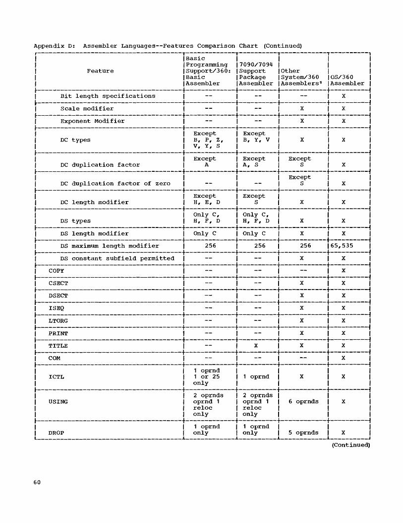
Appendix D: Assembler Languages--Features Comparison Chart (Continued) r--------------------------------------T-------------T----------T------------T-----------, / / Basic / / I / / /Programming /7090/7094 / / / / Feature /Support/360: /Support /Other / / / /Basic /Package /System/360 /OS/360 / / /Assembler /Assembler /Assemblers 1 /Assembler I ~--------------------------------------+-------------+----------+------------+----.------~ I Bit length specifications I I I / X I ~--------------------------------------+-------------+----------+------------+----------~ I Scale modifier I I / X I X I ~--------------------------------------+-------------+----------+------------+----.------~ I Exponent Modifier I I I X I X I ~--------------------------------------+-------------+----------+------------+----------1 I I Except I Except I / I I DC types / B, P, Z, / B, Y, V I X I X I I I V, Y, S I / I / ~--------------------------------------+-------------+----------+------~-----+----------1 I I Except I Except / Except I I I DC duplication factor / A I A, SIS I X / ~--------------.------------------------+-------------+----------+------------+----------1 I I / / Except I / I DC duplication factor of zero / / I S I X /
~--------------------------------------+-------------+----------+------------+----------1 I I Except I Except I I I I DC length modifier I H, E, DIS I X I X I ~--------------------------------------+-------------+----------+------------+----·------1 I I Only C, I Only C, I I I I DS types I H, F, D I H, F, D I X I X I ~--------------------------------------+-------------+----------+------------+----------1 I DS length modifier I Only C I Only C I X I X I ~--------------------------------------+-------------+----------+------------+----------1 I DS maximum length modifier I 256 / 256 I 256 165,535 / ~--------------------------------------+-------------+----------+------------+----------1 I DS constant subfield permitted I I I X I X I ~---------------------------------------+-------------+----------+------------+-----------1 I COpy 1 I I I X I ~-------------------------------------+-------------+----------+------------+-----------1 I CSECT I I I X I X I ~-------------------------------------+------------+----------+------------+----------~ I DSECT I I I X I X I ~--------------------------------------+-------------+----------+------------+----------~ I ISEQ I -- / -- I X / X / ~--------------------------------------+-------------+---------+------------+-----.-----~ / LTORG I I / X / X /
.--------------------------------------+-------------+----------+------------+-----------~ I PRINT I / / X I X I ~--------------------------------------+-------------+----------+-----------+-----------1 I TITLE I / X I X / X /
~--------------------------------------+-------------+----------+------------+-----·-----1 I COM / I / I X / ~-------------------------------------+-------------+----------+------------+----------1 / I 1 oprnd I I I / I ICTL I 1 or 25 / 1 oprnd / X I X / I / only I / / f ~--------------------------------------+-------------+----------+------------+-----·-----1 I I 2 oprnds f 2 oprnds Iff I USING f oprnd 1 f oprnd 1 f 6 oprnds / X f I I reloc / reloc / f / f f only / only f I f ~--------------------------------------+-------------+----------+------------+----------1 I I 1 oprnd I 1 oprnd If/ f DROP I only / only f 5 oprnds f X / L ______________________________________ i _____________ i __________ i ____________ i __________ J
(Continued)
60

Appendix D: Assembler Languages--Features Comparison Chart (Continued) r--------------------------------------T-------------T----------T------------T----------, I I Basic I I I I I I Programming 17090/7094 1 I I I Feature ISupport/360: ISupport I Other 1 I I IBasic I Package ISystem/360 IOS/360 I I I Assembler IAssembler IAssemblers 1 IAssembler I ~--------------------------------------+-------------+----------+------------+----------1 I I oprnd 2 I oprnd 2 I I I I CCW 1 reloc I reloc I X I X I I I only I only I 1 I ~--------------------------------------+-------------+----------+------------+----------1 I I no blank I no blank I I I I ORG I oprnd I oprnd I X I X I ~--------------------------------------+-------------+----------+------------+----------1 I I 1 oprnd I 1 oprnd I 1 oprnd I I I ENTRY I only I only I only I X 1 ~--------------------------------------+-------------+----------+------------+----------1 I I max 1 4 I I I I I EXTRN I 1 oprnd I 1 oprnd I 1 oprnd I X I I I only I only I only I I ~--------------------------------------+-------------+----------+------------+----------~ I I 2 dec I 2 dec 1 2 dec 1 I 1 CNOP I digits I digits I digits I X 1 ~--------------------------------------+-------------+----------+------------+----------1 I PUNCH I I 1 I X I ~--------------------------------------+-------------+----------+------------+----------1 I REPRO I I I I I I I I I X I X I ~--------------------------------------+-------------+----------+------------+----------1 I Macro Instructions I I I X I X I L ______________________________________ ~ _____________ ~ __________ ~ ____________ ~ __________ J
Appendix D 61

APPENDIX E. HEXADECIMAL TO MNEMONIC OPERATION CODE TABLE
The table in this appendix provides for codes to their associated asseInbler mnemoneasy conversion from the hexadecimal equi- ic operation codes. valent of the actual machine operation
Second Hexadecimal Digit
o 1 2 3 4 5 6 7 8 9 A B C D E F r----T----T----T----T----T----T----T----T----T----T----T----T----T----T----T----'
o I I I I ISPM IBALRIBCTRIBCR ISSK IISK ISVC I I I I I I ~----+----+----+----+----+----+----+----+----+----+----+----+----+----+----+----~
1 ILPR ILNR ILTR ILCR INR ICLR lOR IXR ILR ICR IAR ISR IMR IDR IALR ISLR I F ~----+----+----+----+----+----+----+----+----+----+----+----+----+----+----+----~ RR i 2 ILPDRILNORILTDRILCDRIHDR I I I ILDR ICDR IADR ISDR IMDR IDDR IAWR ISWR I r ~----+----+----+----+----+----+----+----+----+----+----+----+----+----+----+----~ s 3 I LPERILNERI LTER I LCERI HER I I IlLER ICER IAER ISER IMER IDER IAUR ISUR I t ~----+----+----+----+----+----+----+----+----+----+----+----+----+----+----+----~
4 ISTH ILA ISTC IIC lEX IBAL IBCT 'BC 'LH ICH lAB ISH 1MB I ,CVD ICVB I ~----+----+----+----+----+----+----+----+----+----+----+----+----+----+----+----~
H 5 I ST I I I , N I CL I 0 I X I L , C I A , S , MID I AL I SL I e ~----+----+----+----+----+----+----+----+----+----+----+----+----+----+----+-----t RX x 6 ISTD I I I I I I I ILD ICD lAD ISD IMD 100 lAW ISW I a ~----+----+----+----+----+----+----+----+----+----+----+----+----+----+----+-.---~ d 7 I STE I I I I I I I I LE I CE I AE I SE I ME I DE I AU I SU I e ~----+----+----+----+----+----+----+----+----+----+----+----+----+_---+----+-.---~ c 8 ISSM I ILPSWI IWRD IRDD IBXH IBXLEISRL ISLL ISRA ISLA ISRDLISLDLISRDAISLDAI i ~----+----+----+----+----+----+----+----+----+----+----+----+----+----+----+-----t m 9 ISTM ITM IMVI ITS INI ICLI IOI IXI ILM I I I ISIO ITIO IHIO ITCH I RS a ~----+----+----+----+----+----+----+----+----+----+----+----+----+----+----+----~ or 1 A I I I I I I I I I I I I I I I I I SI
~----+----+~---+----+----+----+----+----+----+----+----+----+----+----+----+----~ B I I I I I I I I I , I I I I I , ,
D ~----+----+----+----+----+----+----+----+----+----+----+----+----+----+----+-.---~ i C I I I I I I I I I I I , I I , I , g ~----+----+----+----+----+----+----+----+----+----+----+----+----+----+----+-.---~ i D I I MVN I MVC I MVZ 'NC I CLC lOCI XC I I I I I TR I TRT I ED I E1DMK I t ~----+----+----+----+-.---+----+---+----+----+----+----+----+----+----+----+-.---~ SS
E I I I I I I I I I I I I I I I I I I ~----+----+----+----+----+----+----+----+----+----+----+----+----+----+----+-.---~
F limo IPACKIUNPKI , I , IZAP ICP lAP ISP IMP IDP I I I L ____ ~ ____ ~ ____ ~ ___ ~ ____ ~ ____ ~ ____ ~ ____ ~ ____ ~ ____ ~ ____ ~ ____ ~ ____ ~ ____ ~ ____ ~_. ___ J
62
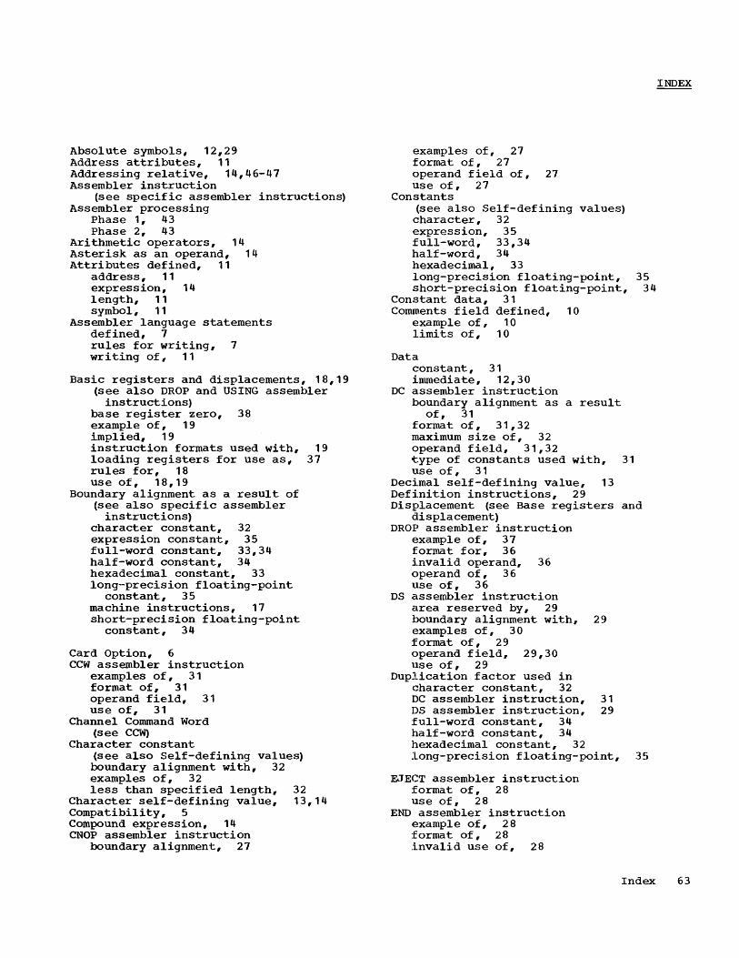
Absolute symbols, 12,29 Address attributes, 11 Addressing relative, 14,46-47 Assembler instruction
(see specific assembler instructions) Assembler processing
Phase 1, 43 Phase 2, 43
Arithmetic operators, 14 Asterisk as an operand, 14 Attributes defined, 11
address, 11 expression, 14 length, 11 symbol, 11
Assembler language statements defined, 7 rules for writing, 7 writing of, 11
Basic registers and displacements, 18,19 (see also DROP and USING assembler
instructions) base register zero, 38 example of, 19 implied, 19 instruction formats used with, 19 loading registers for use as, 37 rules for, 18 us e of, 18,19
Boundary alignment as a result of (see also specific assembler
instructions) character constant, 32 expression constant, 35 full-word constant, 33,34 half-word constant, 34 hexadecimal constant, 33 longo-precision floating-point
constant, 35 machine instructions, 17 short-precision floating-point
constant, 34
Card Option, 6 CCW assembler instruction
examples of, 31 format of, 31 operand field, 31 use of, 31
Channel Command Word (see CCW)
Character constant (see also Self-defining values) boundary alignment with, 32 examples of, 32 less than specified length, 32
Character self-defining value, 13,14 Compatibility, 5 Compound expression, 14 CNOP assembler instruction
boundary alignment, 27
examples of, 27 format of, 27 operand field of, 27 use of, 27
Constants (see also Self-defining values) character, 32 expression, 35 full-word, 33,34 half-word, 34 hexadecimal, 33 long-precision floating-point, short-precision floating-point,
Constant data, 31 Comments field defined, 10
example of, 10 limits of, 10
Data constant, 31 immediate, 12,30
DC assembler instruction boundary alignment as a result
of, 31 format of, 31,32 maximum size of, 32 operand field, 31,32 type of constants used with, 31 use of, 31
35 34
Decimal self-defining value, 13 Definition instructions, 29 Displacement (see Base registers and
displacement) DROP assembler instruction
example of, 37 format for, 36 invalid operand, 36 operand of, 36 use of, 36
DS assembler instruction area reserved by, 29 boundary alignment with, 29 examples of, 30 format of, 29 operand field, 29,30 use of, 29
Duplication factor used in character constant, 32 DC assembler instruction, 31 DS assembler instruction, 29 full-word constant, 34 half-word constant, 34 hexadecimal constant, 32 long-precision floating-point, 35
EJECT assembler instruction format of, 28 use of, 28
END assembler instruction example of, 28 format of, 28 invalid use of, 28
Index 63

operand field of, 28 use of, 28
ENTRY assembler instruction example of, 39 format of, 39 operand field, 39 restrictions on, 39 use of, 39
Entry point, 12 (see also ENTRY assembler
instruction) EQU assembler instruction
examples of, 29 format of, 29 name field of, 29 operand field of, 29 use of, 29
Error Notification, 44 ESD
(see External Symbol Dictionary card)
Explicit length, 19 (see also specific assembler in structions)
Exponent defined, 34 Expressions
absolute, 15 attributes of, 14 compound, 13 defined, 13 relative addressing with, 14 relocatable, 15 restrictions on, 15 simple, 14 terminators of, 14
Expression constant (see also Self-defining values) boundary alignment of, 35 examples of, 35 how specified, 35 length codes of, 35 rules for, 35
EXTERN assembler instruction example of, 40 format of, 39 operand field, 39 restrictions on, 40 use of, 40
External Symbol (see also Symbols), 12,39
External Symbol Dictionary card, 45
Flags, program listing, list of, 44,45 Floating-point constants, long-precision
(see Long-precision floating-point constants)
Floating-point constants, short-precision (see Short-precision floating-point
constants) Formats machine instruction
(see Machine instruction statements) Fraction defined~ 34 Full-word constants
boundary alignment with, 33,34 examples of, 33
Half-word constants
64
boundary alignment, 34 example of, 34 length code of, 34
Hexadecimal constant (see also Self-defining value)
boundary alignment with, 33 examples of, 33 valid digits, 33
Hexadecimal self-defining value, 13
ICTL assembler in~truction format of, 25 required for, 25 use of, 25
Immediate data, 12,30 Implied base register, 19
(see also DROP and USING assemble]::' instructions)
Implied length, 19 Instructions
assembler (see specific assembler instructions)
base register (see DROP and USING assembler instructions)
definition, 29 machine, 17
Invalid fields (see specific fields)
Length attributes, 11,19,20 (see also specific instructions) explicit, 19 implied, 19 invalid, 19
Load end card, 28,45 Loading base registers, 37 Location counter
(see also specific assembler instructi ons)
contents of, 12 defined, 12 maximum value of, 13 overflow of, 13 program listing, 44 programmer use of, 13
Long-preciSion floating-point constant boundary alignment, 35 example of, 35 how specified, 35 invalid fraction or exponent, 35 operand format of, 35
exponent of, 35 fraction of, 35
Machine instruction mnemonics, 20 list of, 21-24
Machine instruction statements, 17 example, 24 writing considerations, 17
Name field (see also Symbols) defined, 9 example of, 9 limits of, 9
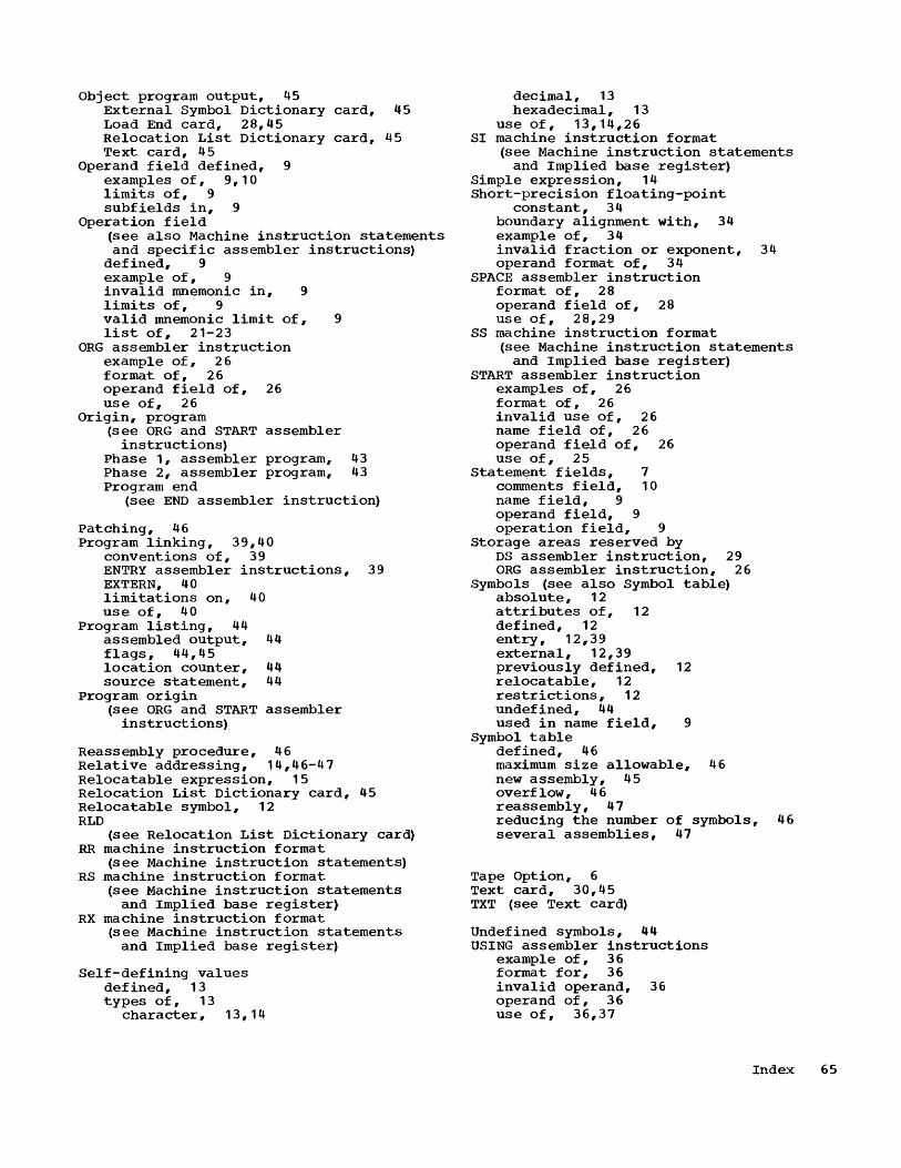
Object program output, 45 External Symbol Dictionary card, 45 Load End card, 28,45 Relocation List Dictionary card, 45 Text card, 45
Operand field defined, 9 examples of, 9,10 limits of, 9 subfields in, 9
Operation field (see also Machine instruction statements and specific assembler instructions)
defined, 9 example of, 9 invalid mnemonic in, 9 limits of, 9 valid mnemonic limit of, 9 list of, 21-23
ORG assembler inst+uction example of, 26 format of, 26 operand field of, 26 use of, 26
Origin, program (see ORG and START assembler
instructions) Phase 1, assembler program, 43 Phase 2, assembler program, 43 Program end
(see END assembler instruction)
patching, 46 Program linking, 39,40
conventions of, 39 ENTRY assembler instructions, 39 EXTERN, 40 limitations on, 40 use of, 40
Program listing, 44 assembled output, 44 flags, 44,45 location counter, 44 source statement, 44
Program origin (see ORG and START assembler
instructions)
Reassembly procedure, 46 Relative addressing, 14,46-47 Relocatable expression, 15 Relocation List Dictionary card, 45 Relocatable symbol, 12 RLD
(s ee Relocation List Dictionary card) RR machine instruction format
(see Machine instruction statements) RS machine instruction format
(see Machine instruction statements and Implied base register)
RX machine instruction format (see Machine instruction statements
and Implied base register)
Self-defining values defined, 13 types of, 13
character, 13,14
decimal, 13 hexadecimal, 13
use of, 13,14,26 SI machine instruction format
(see Machine instruction statements and Implied base register)
Simple expression, 14 Short-precision floating-point
constant, 34 boundary alignment with, 34 example of, 34 invalid fraction or exponent, 34 operand format of, 34
SPACE assembler instruction format of, 28 operand field of, 28 use of, 28,29
SS machine instruction format (see Machine instruction statements
and Implied base register) START assembler instruction
examples of, 26 format of, 26 invalid use of, 26 name field of, 26 operand field of, 26 use of, 25
Statement fields, 7 comments field, 10 name field, 9 operand field, 9 operation field, 9
Storage areas reserved by DS assembler instruction, 29 ORG assembler instruction, 26
Symbols (see also Symbol table) absolute, 12 attributes of, 12 defined, 12 entry, 1 2 , 39 external, 12,39 previously defined, 12 relocatable, 12 restrictions, 12 undefined, 44 used in name field, 9
Symbol table defined, 46 maximum size allowable, 46 new assembly, 45 overflow, 46 reassembly, 47 reducing the number of symbols, 46 several assemblies, 47
Tape Option, 6 Text card, 30,45 TXT (see Text card)
Undefined symbols, 44 USING assembler instructions
example of, 36 format for, 36 invalid operand, 36 operand of, 36 use of, 36,37
Index 65

2/65:20M-EO-68
READER'S COMMENTS
IBM System/360 Basic Programming Support Title: Basic Assembler Language
Is the material: Easy to Read? Well organized? Complete? Well illustrated? Accurate? Suitable for its intended audience?
How did you use this publication?
Yes No
Form :_C_2_8_-_6_5_0_3_-_3 __
As an introduction to the subject __ For additional knowledge Other __________________________ ~ __
Please check the items that describe your position:
fold
__ Customer personnel _ Operator _ IBM personnel _ Programmer _ Manager _Customer Engineer
_ Sales Representative _ Systems Engineer _Trainee
_ Systems Analyst _ Instructor Other ____________ __
Please check specific criticism(s), give page number(s) ,and explain below: __ Clarification on page (s) _ Addi tion on page (s)
~ _ Deletion on page (s) ~ _ Error on page (s) ...:I ~ Explanation: Z o ~
Name ______________________________ ___
Address ____________________________ __
FOLD ON TWO LINES,STAPLE AND MAIL No Postage Necessary if Mailed in U.S.A.
fold
C28-6503-3
fold
fold
r--------------------------------------------------, I BUSINESS REPLY MAIL I , NO POSrAGE STAMP NECESSARY IF MAILED IN U. S. ~. I L __________________________________________________ J
POSTAGE ~ILL BE PAID BY
IBM CORPORATION P. O. BOX 390 POUGHKEEPSIE, N. Y. 12602
ATTN: PROGRAMMING SYSTEMS PUBLICATIONS DEPT. 058
llJ]5~ (!)
International Business Machines Corporation Data Processing Division 112 East Post Road, White Plains, N. Y. 10601
staple
r---------------------, I FIRST CLASS I I PERMIT NO. 81 , I I I I I POUGHKEEPSIE, N. Y. I L _____________________ J
111111 , , II , I
111111
111111
111111
111111
111111
111111
111111
111111
I " III
fold
fold
staple
~ Z .... ..::a t!) z
~ ~ 0
'"t1 Ii ..... ::1 M" CD 0.. ..... ::1
c: en ~ .
() ' ..
"->
~" '" tTl o W J
W


![Early computer systems Operating System one job at a time · Early computer systems No OS ... one job at a time IBM System 360 OS 360 (IBM) [1965] multitasking pagination assembly](https://static.fdocuments.us/doc/165x107/5e7624c20eefe91240043f23/early-computer-systems-operating-system-one-job-at-a-early-computer-systems-no-os.jpg)


