Systems in Transport Airplanes - Hunt Library
136
Safety Report on the Treatment of Safety-Critical Systems in Transport Airplanes Safety Report NTSB/SR-06/02 PB2006-917003 Notation 7752A National Transportation Safety Board Washington, D.C.
Transcript of Systems in Transport Airplanes - Hunt Library

Safety Report on the Treatment of Safety-CriticalSystems in Transport Airplanes
Safety ReportNTSB/SR-06/02
PB2006-917003Notation 7752A
National TransportationSafety BoardWashington, D.C.
National TransportationSafety BoardWashington, D.C.
National TransportationSafety BoardWashington, D.C. 20594
OFFICIAL BUSINESSPenalty for Private Use, $300
PRSRT STD
Postage & Fees Paid
NTSB
Permit No. G-200


Safety ReportSafety Report on the Treatment of Safety-Critical Systems in Transport Airplanes
NTSB/SR-06/02PB2006-917003 National Transportation Safety BoardNotation 7752A 490 L’Enfant Plaza, S.W.Adopted April 25, 2006 Washington, D.C. 20594

National Transportation Safety Board. 2006. Safety Report on the Treatment of Safety-CriticalSystems in Transport Airplanes. Safety Report NTSB/SR-06/02. Washington, DC.
Abstract: Certification of systems that are critical to the safety of flight has been the focus ofseveral recently concluded National Transportation Safety Board accident investigations oftransport-category airplanes: USAir flight 427 in 1999; TWA flight 800 in 2000; Alaska Airlinesflight 261 in 2002; and American Airlines flight 587 in 2004. Each of these investigations raisedquestions about the certification process used by the FAA to determine compliance withairworthiness standards.
The purpose of this safety report is to discuss the concerns about certification raised in thoseinvestigations and to identify process improvements to FAA’s type certification of safety-criticalsystems in transport-category airplanes. The report includes three recommendations in two areas.The first area concerns the ways in which hazards to safety of flight are identified, assessed, anddocumented during the type certification process. The Safety Board’s analysis considered howcompliance with Federal regulations is demonstrated and how the safety assessment effort isdocumented. Of particular concern were assessments of safety-critical systems that do not includecertain structural failure conditions and human/system interaction failures.
The second area focused on the ongoing assessment of safety-critical systems throughout the lifeof the airplane. The Board concluded that a program must be in place, once the type certificationprocess is completed, to ensure the ongoing assessment of risks to safety-critical systems. Such aprogram must recognize that ongoing decisions about design, operations, maintenance, andcontinued airworthiness must be done in light of operational data, service history, lessons learned,and new knowledge, for designs that are derivatives of previously certificated airplanes.
The National Transportation Safety Board is an independent Federal agency dedicated to promoting aviation, railroad, highway, marine,pipeline, and hazardous materials safety. Established in 1967, the agency is mandated by Congress through the Independent Safety BoardAct of 1974 to investigate transportation accidents, determine the probable causes of the accidents, issue safety recommendations, studytransportation safety issues, and evaluate the safety effectiveness of government agencies involved in transportation. The Safety Boardmakes public its actions and decisions through accident reports, safety studies, special investigation reports, safety recommendations, andstatistical reviews.
Recent publications are available in their entirety on the Web at <http://www.ntsb.gov>. Other information about available publications alsomay be obtained from the Web site or by contacting:
National Transportation Safety BoardRecords Management Division, CIO-40490 L’Enfant Plaza, S.W.Washington, D.C. 20594(800) 877-6799 or (202) 314-6551
Safety Board publications may be purchased, by individual copy or by subscription, from the National Technical Information Service. Topurchase this publication, order report number PB2006-917003 from:
National Technical Information Service5285 Port Royal RoadSpringfield, Virginia 22161(800) 553-6847 or (703) 605-6000
The Independent Safety Board Act, as codified at 49 U.S.C. Section 1154(b), precludes the admission into evidence or use of Board reportsrelated to an incident or accident in a civil action for damages resulting from a matter mentioned in the report.

iii Safety Report
Contents
Contents .................................................................................................................................................... iii
Acronyms and Abbreviations ........................................................................................................... v
Executive Summary ........................................................................................................................... viii
Introduction ............................................................................................................................................ 1
Certification Issues in Accident Investigation ........................................................................... 6USAir Flight 427 ........................................................................................................................................... 6
Certification Issues .............................................................................................................................. 10TWA Flight 800 ........................................................................................................................................... 11
Certification Issues .............................................................................................................................. 15Alaska Airlines Flight 261 ........................................................................................................................... 16
Certification Issues .............................................................................................................................. 21American Airlines Flight 587 ...................................................................................................................... 23
Certification Issues .............................................................................................................................. 29
Methodology for Examining Type Certification ..................................................................... 31The FAA Certification Process .................................................................................................................... 31Establishing the Type Certification Basis .................................................................................................... 33Demonstrating Compliance ......................................................................................................................... 35Fail-Safe Design Concept ............................................................................................................................ 37Conducting Safety Assessments .................................................................................................................. 40Post-Certification Processes ........................................................................................................................ 43
Other Efforts to Study Certification ............................................................................................ 46FAA Commercial Airplane Certification Process Study ............................................................................. 46RTCA Task Force 4 on Certification ........................................................................................................... 47National Research Council Report on Improving Continued Airworthiness .............................................. 48
Analysis .................................................................................................................................................... 50Identifying and Assessing Safety-Critical Systems ..................................................................................... 50Excluding Structural Failures from Safety Assessments ............................................................................. 52Excluding Human Error from Safety Assessments ..................................................................................... 53Monitoring and the Ongoing Assessment of Safety-Critical Systems ........................................................ 55
Conclusions ............................................................................................................................................ 60
Recommendations ............................................................................................................................... 61
Resource Documents .......................................................................................................................... 62

Contents iv Safety Report
AppendixesA: Type Certification Process Description ...................................................................... 67B: Certification Process Tables .......................................................................................... 100C: Transport-Category Airplane-Related Accidents ................................................ 115D: Status and Disposition of NTSB Safety Recommendations ............................. 120

v Safety Report
Acronyms and Abbreviations
AAI Office of Accident InvestigationAAM Office of Aerospace MedicineAAMP Advanced Aircraft Maneuvering Program AC advisory circularACE-100 Small Airplane DirectorateACO Aircraft Certification OfficeACSEP Aircraft Certification Evaluation System AD airworthiness directive AEG Aircraft Evaluation Group AFS Flight Standards AIR Aircraft Certification ServiceANM-100 Transport Airplane DirectorateAPC aircraft-pilot coupling ARAC Aviation Rulemaking Advisory Committee ATM air traffic managementATOS Air Transportation Oversight System AVS Associate Administrator for Aviation Safety CDR critical design reviewCFR Code of Federal Regulations CIR conformity inspection reportCM Condition Monitoring CMT Certificate Management Team CNS communications, navigation, surveillanceCPS Commercial Airplane Certification Process StudyCMR Certification Maintenance RequirementCWT center wing fuel tankDAR Designated Airworthiness Representative DER Designated Engineering Representative DMIR Designated Manufacturing Inspection Representative DoD Department of DefenseDODD Department of Defense Directive DODI DoD Instruction

Acronyms and Abbreviations vi Safety Report
EASA European Aviation Safety AuthorityETEB Flight Control Engineering Test and Evaluation Board ETOPS Extended-Range Twin-Engine Operations FAA Federal Aviation Administration FAR Federal Aviation Regulation FDR flight data recorder FHA functional hazard assessment FMEA failure modes and effects analysis FMES failure modes and effects summary FOEB Flight Operations Evaluation Board FSB Flight Standardization Board FTA fault tree analysisFTA Federal Transit Administration GAO General Accounting Office HRA human reliability analysisHT HardtimeICA instructions for continued airworthiness ISC industry steering committee
JAA Joint Aviation AuthorityJAR Joint Aviation RequirementMED multiple element damageMRB Maintenance Review Board MSD multiple site damageMSG Maintenance Steering GroupNAS National Airspace SystemNASA National Aeronautics and Space AdministrationNPRM Notice of Proposed Rule-Making NRC National Research Council NRC Nuclear Regulatory CommissionNRS national resource specialistOAMP On-Aircraft Maintenance Planning OC On-Condition PCU power control unit PM project manager PO project officerPPH policy and procedures handbook

Acronyms and Abbreviations vii Safety Report
PRA probabilistic risk assessmentPSCP Project Specific Certification Plan PSE principal structural elementPSP Partnership for Safety Plan PSSA preliminary system safety assessmentSAE Society of Automotive Engineers SCR special certification review SSI Structural Significant ItemTC type certificate TCB Type Certification Board TCDS Type Certificate Data Sheet TIA Type Inspection Authorization TIR Type Inspection ReportVA design maneuvering speed WG working group

viii Safety Report
Executive Summary
Certification of systems that are critical to the safety of flight has been the focus ofseveral recently completed National Transportation Safety Board accident investigationsof transport-category airplanes: the rudder actuator in USAir flight 427 in 1999; thecenter wing fuel tank in TWA flight 800 in 2000; the horizontal stabilizer jackscrew inAlaska Airlines flight 261 in 2002; and the rudder system in American Airlines flight 587in 2004. Each of these investigations raised questions about the certification process usedby the FAA to determine compliance with airworthiness standards.
The purpose of this safety report is to discuss the concerns about certificationraised in those investigations and to identify process improvements to FAA’s typecertification of safety-critical systems in transport-category airplanes. The Safety Boardrecognizes that the findings in this report are presented during one of the safest periods incommercial aviation history and acknowledges that FAA’s certification process hascontributed significantly to that level of safety. However, the Board notes that there isroom for improvement.
The report includes three recommendations in two areas. The first area concernsthe ways in which hazards to safety of flight are identified, assessed, and documentedduring the type certification process. The Safety Board’s analysis considered howcompliance with Federal regulations is demonstrated and how the safety assessment effortis documented. Of particular concern were assessments of safety-critical systems that donot include certain structural failure conditions and human/system interaction failures.
The second area focuses on the ongoing assessment of safety-critical systemsthroughout the life of the airplane. The Board concluded that a program must be in place,once the type certification process is completed, to ensure the ongoing assessment of risksto safety-critical systems. Such a program must recognize that ongoing decisions aboutdesign, operations, maintenance, and continued airworthiness must be done in light ofoperational data, service history, lessons learned, and new knowledge, for designs that arederivatives of previously certificated airplanes.

1 Safety Report
Introduction
Certification of systems that are critical to the safety of flight has been the focus ofseveral recently completed National Transportation Safety Board accident investigationsof transport-category airplanes. In 1999, the Safety Board expressed concern about theFederal Aviation Administration’s (FAA) certification process during its investigation ofthe rudder actuator in USAir flight 427.1 In 2000, the Board suggested the need for adirected examination of the certification process in the investigation of the center wingfuel tank in TWA flight 800.2 Subsequent investigations of the horizontal stabilizerjackscrew in Alaska Airlines flight 2613 and the rudder system in American Airlines flight5874 also raised questions about the certification process used by the FAA to determinecompliance with airworthiness standards. These four accidents resulted in 715 fatalitiesand accounted for 60 percent of the air carrier fatalities that occurred from 1994–2001.5
The purpose of this report is to discuss those concerns in more detail and toidentify possible improvements to FAA’s certification process for safety-critical systemsin transport-category airplanes.6 The seriousness of the four accidents listed above, inwhich critical systems suffered catastrophic failure, prompted the Safety Board toundertake this directed examination of the processes used by the FAA to assess safety-critical systems. The Board recognizes that the findings in this report are presented duringone of the safest periods in commercial aviation history and acknowledges that FAA’scertification process has contributed significantly to that level of safety. The Boardbelieves, however, that these four major aviation accidents, when considered together, canin hindsight illustrate where process improvements can be made.
1 Uncontrolled Descent and Collision with Terrain, USAir Flight 427, Boeing 737-300, N513AU NearAliquippa, Pennsylvania, September 8, 1994, Aircraft Accident Report NTSB/AAR-99/01 (Washington,DC: National Transportation Safety Board, 1999), p. 281. As a result of this investigation, the Safety Boardrevised its report of the United Airlines flight 585 accident.
2 In-flight Breakup Over the Atlantic Ocean, Trans World Airlines Flight 800, Boeing 747-131,N93119, Near East Moriches, New York, July 17, 1996, Aircraft Accident Report NTSB/AAR-00/03(Washington, DC: National Transportation Safety Board, 2000), p. 298.
3 Loss of Control and Impact with Pacific Ocean, Alaska Airlines Flight 261, McDonnell DouglasMD-83, N963AS, About 2.7 Miles North of Anacapa Island, California, January 31, 2000, Aircraft AccidentReport NTSB/AAR-02/01 (Washington, DC: National Transportation Safety Board, 2002).
4 In-Flight Separation of Vertical Stabilizer, American Airlines Flight 587, Airbus Industrie A300-605R,N14053, Belle Harbor, New York, November 12, 2001, Aircraft Accident Report NTSB/AAR-04/04(Washington, DC: National Transportation Safety Board, October 26, 2004).
5 The airplanes involved in these four accidents operate under the authority of 14 CFR Part 121, whichspecifies the operating requirements for domestic, flag, and supplemental air carrier operations. From 1994–2001, 24 fatal Part 121 accidents resulted in 1,166 fatalities, excluding the events of September 11, 2001.
6 A transport-category airplane is defined in Federal Aviation Regulations as all jets with 10 or more seatsor greater than 12,500-pound Maximum Takeoff Weight, and all propeller driven airplanes with greater than 19seats or greater than 19,000-pound Maximum Takeoff Weight. The definition of a transport-category airplane isprovided by the FAA at <http://www.faa.gov/aircraft/air_cert/design_approvals/transport/>.

Introduction 2 Safety Report
The Safety Board limited the scope of this report to the type certification oftransport-category airplanes and the processes that the FAA uses to assess risks to safety-critical systems. The Board found that the FAA’s type certification process is sound andproduces a high level of safety, but improvements are warranted for the following reasons:
1. The process for assessing risks to aircraft systems does not adequately addressimportant failure conditions associated with structures and with human/systeminteraction.
2. The results of the process for assessing risks to safety-critical systems are notadequately preserved to support continued airworthiness of certificatedairplanes.
3. Existing policy, practices, and procedures for the ongoing assessment of risksto safety-critical systems do not ensure that the underlying assumptions madeduring design and certification are adequately and continuously assessed inlight of operational experience, lessons learned, and new knowledge.
Consequently, this report includes recommendations, in two areas, forimprovements in type certification and the treatment of safety-critical systems. The firstarea concerns the ways in which hazards7 to safety of flight are identified, assessed, anddocumented during the type certification process. The Safety Board’s analysis considersthe ways in which compliance with federal regulations is demonstrated and how the safetyassessment effort is documented. Of particular concern are assessments of safety-criticalsystems that do not include certain structural failure conditions and human/systeminteraction failures.
The second area focuses on the monitoring and ongoing assessment of safety-criticalsystems throughout the life of the airplane. Once hazards to safety of flight have beenidentified, assessed, and eliminated or controlled during certification, a program must bein place to ensure continued airworthiness and the ongoing assessment of risks to safety-critical systems. Such a program can recognize that the certification process can changethroughout the life of an airplane and that ongoing decisions about design, operations,maintenance, and continued airworthiness must be done in light of operational data,service history, lessons learned, and new knowledge. This is especially true for airplanedesigns that were certificated many years before any changes in the certification processoccurred. To that end, this report also considers the relationship between the FAA’sAircraft Certification Service (AIR) and Flight Standards (AFS).
The safety assessment process, which is governed by 14 Code of FederalRegulations (CFR) 25.1309, “Equipment, Systems, and Installations,” and described inFAA Advisory Circular (AC) 25.1309-1A, System Design and Analysis, is used during
7 This report uses U.S. Department of Transportation, Federal Aviation Administration Order 8040.4,Safety Risk Management, Appendix 1, to define a hazard as a condition, event, or circumstance that couldlead to or contribute to an unplanned or undesired event. This definition is also consistent with U.S.Department of Defense Standard Practice for System Safety, MIL-STD-882D, which defines a hazard as“any real or potential condition that can cause injury, illness, or death to personnel; damage to or loss of asystem, equipment or property; or damage to the environment.”

Introduction 3 Safety Report
certification to identify and analyze safety-critical functions performed by systems. It isworth noting that neither certification regulations nor advisory materials provide a list ofsafety-critical functions or the systems associated with them, nor do they explicitly definethe term “safety-critical.”8 As this report will show, the criticality of systems isdetermined during type certification through a safety assessment process that evaluates“the effects on safety of foreseeable failures or other events, such as errors or externalcircumstances, separately or in combination, involving one or more system functions.”9
This is the position taken by the FAA in its most recent policy on the identification andevaluation of “flight critical system components”10 and is consistent with industry practicefor assessing the criticality of hazards to safety of flight.11 For the sake of clarity, thisreport employs the following working definition: a safety-critical system is one where afailure condition12 would prevent the safe flight of the airplane, or would reduce thecapability of the airplane or the ability of the crew to cope with adverse operatingconditions. This definition focuses on the severity of a failure condition and how thatfailure affects the functional capability of the overall airplane system—a definition that isconsistent with FAA regulations and advisory materials,13 FAA system safety guidelines,14
Department of Defense (DoD) system safety standards,15 and industry-recommendedpractice.16
8 U.S. Department of Transportation, Federal Aviation Administration Advisory Circular (AC)25.1309-1A, System Design and Analysis, June 21, 1988, refers only to “safety-critical functions” withoutdefining them.
9 AC 25.1309-1A, System Design and Analysis, June 21, 1988, paragraph 7a.10 U.S. Department of Transportation, Federal Aviation Administration Memorandum ANM-03-117-10
Identification of Flight Critical System Components, July 24, 2003.11 Guidelines and Methods for Conducting the Safety Assessment Process on Civil Airborne Systems
and Equipment, Society of Automotive Engineers (SAE) ARP4761 (Warrendale, PA: Society of AutomotiveEngineers, 1996).
12 AC 25.1309-1A, paragraph 6, defines a failure condition as the “effects on the airplane and itsoccupants, both direct and consequential, caused or contributed to by one or more failures, consideringrelevant adverse operational or environment conditions.” A failure is a “loss of function, or a malfunction,of a system or a part thereof.”
13 As referenced in 14 CFR 25.1309, and as defined in AC 25.1309-1A.14 System Safety Handbook: Practices and Guidelines for Conducting System Safety Engineering and
Management (Washington, DC: Federal Aviation Administration, 2000).15 U.S. Department of Defense, MIL-STD-882D, Standard Practice for System Safety, Appendix A,
paragraph A.3.2.10.16 Safety Assessment of Transport Airplanes in Commercial Service SAE ARP5150 (Warrendale,
Pennsylvania: Society of Automotive Engineers, 2003) and SAE ARP4761.

Introduction 4 Safety Report
Type certification is a regulatory process that the FAA uses to ensure that thedesign of a transport-category airplane meets applicable safety standards. Safety standardsare embodied in Federal Aviation Regulations (FARs),17 with associated guidanceprovided in directives18 and advisory circulars.19 Unlike engineering design that mustbalance potentially conflicting safety, cost, schedule, performance, aesthetic, andmanufacturing elements of a design, certification focuses on a single aspect of thedesign—safety—to ensure that it meets the minimum standards established by law. TheSafety Board recognizes that issuing a type certificate (TC) is just one of the first steps inthe life of a transport-category airplane, and any recommended changes to the typecertification process may have significant implications for operations and formaintenance. Although this report focuses on type certification, the analysis considerssafety-critical systems within the overall context of the life cycle of the airplane.
This report is organized as follows:
• A review of selected major accident investigations to illustrate the role ofcertification in identifying, evaluating, and tracking safety-critical systems.
• An examination of the type certification process, specifically emphasizingmethods and techniques used during certification to assess safety-criticalsystems.
• A review of other FAA certification process studies, noting parallels betweenSafety Board findings and the results of those studies.
• An analysis of key certification concerns and relevant issues, with conclusionsand recommendations.
The four accident case studies discussed in the next section provide an accidentinvestigation context for the Safety Board’s concerns about type certification. In each ofthese accidents, the Board identified a specific safety-critical system and the failure modes
17 As stated in U.S. Department of Transportation, Federal Aviation Administration Order 8100.5A,Aircraft Certification Service: Mission, Responsibilities, Relationships, and Programs, September 30, 2003,paragraph 4.1:
AVIATION REGULATIONS are in 14 CFR. These regulations set the minimumrequirements for certification and alteration of civil aviation products and otherappliances, and for the approval of FAA designees.
18 As stated in FAA Order 8100.5A, paragraph 4.2: DIRECTIVES are comprised of FAA orders and notices. The FAA staff developsdirectives for FAA personnel, designees, and delegated organizations. Directives transmitinformation, guidance, policy, instructions, and mandatory procedures for AIR to carry outits mission. Directives are internal, intended for FAA employees. Notices transmit similarinformation as orders and are for internal FAA use. Unlike orders, which remain in forceuntil canceled, notices expire 1 year after they are issued.
19 As stated in FAA Order 8100.5A, paragraph 4.3: ADVISORY CIRCULARS (AC) are written for the aviation industry (such asmanufacturers, designers, and installers), FAA customers, and the public. ACs show anacceptable way, but not the only way, for the reader to comply with a certificationrequirement or set of certification requirements. ACs may also show how to comply with aregulation, or how to harmonize implementation for the international aviation community.ACs do not have the force of regulations.

Introduction 5 Safety Report
that resulted in the catastrophic loss of that system, recommended design reviews of thatsystem, and called for FAA action to ensure that any changes to the design, operationalprocedures, or maintenance practices were implemented. This report uses these fouraccidents to examine specific aspects of FAA’s type certification process and includesselected facts, analyses, conclusions, and recommendations from the accidentinvestigations as they were presented in the original Board aircraft accident reports, whichare available on the Safety Board’s website at <www.ntsb.gov/Publictn/A_Acc1.htm)>.

6 Safety Report
Certification Issues in Accident Investigation
The feasibility of using an accident-based, data-driven methodology wasconsidered in the planned approach to this report. A set of candidate accidents was derivedfrom worldwide accident investigation records from 1962–2001. Initially, staff talked withinvestigators and engineers to identify a candidate list of aircraft-related accidents. TheSafety Board’s Office of Aviation Safety (AS) reviewed this list to confirm that theaccidents were good candidates for researching certification issues. Board accident recordsand those of other investigative organizations were analyzed for potential certificationissues. The 55 accidents listed in Appendix C were then identified and categorized in termsof the aircraft component or system that failed. Because information about certification wasnot routinely collected during many of these investigations, a statistical treatment ofaccident-related certification issues was not possible. However, the four accidents reviewedin the following sections provided the extensive documentation needed to addresscertification-related issues, and are used to support a case study analysis of the issue.
USAir Flight 427
On September 8, 1994, a Boeing 737-300 being operated as USAir flight 427entered an uncontrolled descent while maneuvering to land at Pittsburgh International andcrashed into hilly, wooded terrain about 6 miles northwest of the airport. The airplane wasdestroyed by impact forces and fire and all 132 occupants were killed. After a lengthyinvestigation, the Safety Board determined the probable cause of the accident as follows:
A loss of control of the airplane resulting from the movement of the rudder to itsblowdown limit. The rudder surface most likely deflected in a direction oppositeto that commanded by the pilots as a result of a jam of the main rudder powercontrol unit servo valve secondary slide to the servo valve housing offset from itsneutral position and overtravel of the primary slide.20
The investigation also discovered that when a full rudder reversal occurred undercertain flight conditions (flaps 1 position21 and airspeed below 187 knots), pilots wouldnot be able to stop the subsequent roll with full deflection of the ailerons.22
In its final report on USAir flight 427, issued in 1999, the Safety Board found that “thedual-concentric servo valve used in all Boeing 737 main rudder power control units is notreliably redundant.”23 The main rudder power control unit (PCU) operates by converting
20 USAir flight 427, NTSB/AAR-99/01, p. 295.21 By selecting the flaps 1 position, the flaps are fully extended and the trailing edge moves down 1 degree.22 USAir flight 427, NTSB/AAR-99/01, p. 63-64.23 USAir flight 427, NTSB/AAR-99/01, p. 294.

Certification Issues 7 Safety Report
either a mechanical input from the rudder pedals or by an electrical signal from the yawdamper system into motion of the rudder. The PCU moves the rudder when actuated by rudderpedal or trim inputs or by an electrical signal from the yaw damper. The 737 PCU servo valveis a dual-concentric tandem valve composed of a primary slide that moves within a secondaryslide, which in turn moves within the servo valve housing. When rudder motion iscommanded, the internal input shaft moves the servo slides so that the rudder system hydrauliccircuits are connected and the flow of hydraulic fluid moves the rudder.24 The 737 is the onlytwin-engine, transport-category airplane with wing-mounted engines that is designed with asingle panel rudder controlled by a single actuator. Both the Boeing 757 and the 767 use threeindependent, redundant actuators that do not rely on dual concentric servo valves. The 757 and767 design allows pilot input to overpower a failed or jammed actuator valve and eliminatesthe possibility of the failed PCU controlling the movement of a flight surface.
Early in the design and certification of the rudder servo valve, two potentialproblems were identified and corrected: the potential for a jammed servo valve to lead to amalfunction of the rudder control system and the potential for a reversal of hydraulic fluidflow in the servo valve. (A timeline of significant events discussed in the investigation isshown in figure 1.)
The first problem, the potential for a jam in the servo valve, was addressed duringthe certification of the Boeing 737-100 and -200 series airplanes in 1965. At that time,FAA certification personnel raised questions about the redundancy of the single panel,power-activated rudder design.25 Boeing responded that the servo valve assembly wouldaccommodate a single jam without loss of control because, if either slide in the servojammed, the other slide would still move and connect the proper flow paths. AdditionalBoeing analysis showed that aileron roll control authority exceeded rudder controlauthority at all rudder angles, implying that any roll resulting from a jammed servo unitcould be countered with aileron input. Not until 1995, during the USAir flight 427investigation, did testing reveal that full deflection of the ailerons could not overcome theroll generated by full deflection of the rudder if airspeed was below 187 knots with theairplane in the flaps 1 position.
The second problem, the potential for a reversal of hydraulic fluid flow in the servovalve, was detected in a prototype of the 737 and was corrected in 1966; engineeringdocuments from that year revealed that changes were made to the prototype to “insureaccumulated tolerances will not cause reverse flow”26 and to remove the potential forsecondary slide overtravel. In 1999, Parker Hannefin stated in its letter to the Safety Board that“reverse flow” referred to cross-flow or higher-than-desirable internal leakage in the servovalve and was not related to a reversal in the dual-concentric valve.27 For both problems, theFAA accepted the solutions that were incorporated into the design during certification.
24 A detailed explanation of the main rudder PCU and servo valve design and operation can be found inUSAir flight 427, NTSB/AAR-99/01, pp. 29-33.
25 USAir flight 427, NTSB/AAR-99/01, p. 164.26 USAir flight 427, NTSB/AAR-99/01, p. 32.27 USAir flight 427, NTSB/AAR-99/01, p. 32.

Certification Issues 8 Safety Report
When simulator tests of various flight control and system failure scenarios wereconducted in 1994, only a rudder hardover scenario produced results consistent with dataobtained from the USAir flight 427 flight data recorder (FDR). This result promptedadditional investigation of rudder hardover scenarios and focused attention on the PCU.Evidence that implicated the servo valve was not obtained until almost 2 years later in1996 when thermal tests of the PCU—where hot hydraulic fluid was injected into a coldPCU—showed that the secondary slide in the servo unit could jam and that subsequentovertravel of the primary slide could result in an increased system return flow that couldcause a rudder actuator reversal.28
Several 737 rudder incidents came to light during the USAir flight 427investigation. In June 1996, Eastwind flight 517 experienced a yaw/roll upset at 4,000feet during its approach to land at the Richmond, Virginia, airport. The airplane yawedabruptly to the right and then rolled to the right. The captain, who was flying the airplane,reported applying immediate full left rudder and aileron input, and that the rudder pedalfelt stiff and did not respond as normal. The captain had to advance the right throttle toobtain differential power to stop the rolling tendency of the airplane. The upset eventended when the crew performed the emergency checklist and disconnected the yawdamper. Review of the airplane’s logbook records showed a series of flight crew-reported
Figure 1. Chronology of Significant Events Discussed in USAir flight 427 Investigation
28 USAir flight 427, NTSB/AAR-99/01, p. 80.
1966 1967 1968 1969 1970 1971 1972 1973 1974 1975 1976 1977 1978 1979 1980 1981 1982 1983 1984 1985
1987 1988 1989 1990 1991 1992 1993 1994 1995 1996 1997 1998 1999 2000 2001 2002
7/1971
B737-100
TC Issued
11/1984
B737-300
TC Issued
3/1991
United flight 585
Accident
3/2001
United flight 585
Revised Report
9/2000
FAA ETEB Final Report
Recommends
New Rudder Design10/2002
FAA Mandates
New B737
Rudder Design
3/1999
USAir flight 427
NTSB Final Report
5/1999
FAA ETEB
Convened
3/1994
1st Servo Valve
Redesign
AD-94-01-07
8/1997
2nd Servo Valve
Redesign
AD-97-14-049/1994
USAir flight 427
Accident7/1992
United Airlines
Ground Check
PCU Anomaly
10/1982
Parker-Hannefin
PCU Anomaly Tests 1 & 2
1/1984
Parker-Hannefin
PCU Anomaly Test 3
10/1994
FAA CDR
Convened
6/1996
Eastwind flight 517
Incident
5/1965
FAA Raises Question
About Rudder Design
During Certification
10/1987
Accident Airplane
Placed in Service

Certification Issues 9 Safety Report
rudder-related anomalies,29 and a review of the incident airplane’s rudder systemcomponents revealed several anomalous conditions.30 The final report for the USAirflight 427 investigation also documented a number of related incidents that occurred from1974 to 1995, including servo slide jams due to debris and corrosion, insufficient lock nuttorque, and a PCU anomaly and jam when tested at colder temperatures under hydraulicpressure.31
Another incident of note was the rudder reversal and rudder jam during groundoperations of a 737 in 1992.32 During a preflight rudder control ground check atChicago-O’Hare International Airport, the captain of a United Airlines 737-300 reportedthat the left rudder pedal stopped and jammed at about 25 percent pedal travel. Thecaptain reported that he had been moving the rudder pedals back and forth rapidly, andwhen he removed foot pressure from the left pedal, it returned to a neutral position. ThePCU was removed from the aircraft, and subsequent testing showed that the secondaryslide could move beyond its design limits, allowing an abnormal flow that would producea rudder reversal. These results suggested that the problem of accumulated tolerancesidentified in the original prototype was still evident. In November 1992, the Safety Boardrecommended a design review of the dual-concentric servo valves with a design similar tothe 737, and design changes of the servo valve that would preclude the possibility ofrudder reversals attributed to the overtravel of the secondary slide.33
In light of this evidence, the FAA issued Airworthiness Directive (AD) 94-01-07in March 1994 aimed at the overtravel problem. The AD established new inspectioncriteria for main rudder PCUs and required installation of the redesigned servo valve in all737s within the next 5 years. The servo valve was redesigned again in 1996 after theSafety Board’s USAir flight 427 PCU tests revealed the potential for primary valveovertravel if the secondary slide jammed. However, in 1998 this new servo valve wasfound to suffer from cracking problems and was associated with two in-flight rudderanomalies in 1999.
In its final report on USAir flight 427, the Safety Board concluded that redundancyin the dual-concentric servo valve design in existing Boeing 737 main rudder PCUs wascompromised for the following reasons: no method existed for the pilot to reliably detectthe presence of a jammed primary or secondary slide within the servo valve; the dual-concentric servo valve design allowed for failure modes in which one slide could affectthe operation of the other slide; recent design changes did not eliminate the possibility thata maintenance error could result in a servo valve anomaly; and the dual load path providedstructural redundancy, but not functional redundancy. The Board also pointed out that
29 USAir flight 427, NTSB/AAR-99/01, p. 263.30 USAir flight 427, NTSB/AAR-99/01, p. 264. Evidence included a misadjusted yaw damper and
chafed wiring between the yaw damper coupling and the main rudder PCU. Examination of the PCU alsorevealed similarities to the USAir flight 427 servo valve, including relatively tight clearances that are more likely to jam.
31 USAir flight 427, NTSB/AAR-99/01, pp. 148-157.32 USAir flight 427, NTSB/AAR-99/01, pp. 152-154.33 NTSB Safety Recommendations A-92-120 and 121; full text and status are shown in Appendix D.

Certification Issues 10 Safety Report
during certification of the Boeing 737-100 series, the FAA had expressed concern aboutthe airplane’s single-panel, single-actuator rudder system and “recognized the possibilityof undetected latent failures in the servo valve, thereby negating the system’sredundancy.” The Board went on to state that “the rudder system’s history of servicedifficulties (some of which still remain unresolved), particularly the servo valve’s historyof jamming, validates those concerns.”34
In 1999, just 2 months after the Safety Board issued its final report on USAir flight427, the FAA established the government/industry Boeing 737 Flight Control EngineeringTest and Evaluation Board (ETEB). The ETEB was formed in response to Safety BoardRecommendation A-99-21 to the FAA, which was issued as a result of the USAir flight427 investigation:
Conduct a failure analysis to identify potential failure modes, a component andsubsystem test to isolate particular failure modes found during the failure analysis,and a full-scale integrated systems test of the Boeing 737 rudder actuation andcontrol system to identify potential latent failures and validate operation of thesystem without regard to minimum certification standards and requirements inTitle 14 of the Code of Federal Regulations (14 CFR) part 25.35
The ETEB conducted a comprehensive analysis of the Boeing 737 rudder systemand found multiple failure modes. As a result of its analysis, the ETEB issued a finalreport in September 2000 recommending the redesign and retrofit of a new rudder controlsystem. The Safety Board’s response to the ETEB proposal was favorable in that theresult was consistent with investigative findings.36
The investigation of USAir flight 427 also prompted the Safety Board toreconsider the conclusions of a similar Boeing 737 accident. On March 3, 1991, UnitedAirlines flight 585 crashed while maneuvering to land at Colorado Springs, Colorado,killing all 25 people onboard. The final report issued by the Board on December 8, 1992,concluded that it “could not identify conclusive evidence to explain the loss of UnitedAirlines flight 585.” In light of the investigative work on USAir flight 427, the Boardreexamined evidence for the flight 585 accident, issued an updated final report inMarch 2001, and concluded that a rudder reversal was caused by the jam of the rudderservo unit.
Certification IssuesThe Safety Board believes that the investigations of USAir flight 427 and United
flight 585 provide insights into a number of certification issues. First, the Board isconcerned that the ability to completely characterize failure modes in a safety-criticalsystem during certification may be compromised by incomplete or inadequate engineeringanalysis. The USAir flight 427 investigation, the FAA’s critical design review (CDR)
34 USAir flight 427, NTSB/AAR-99/01, p. 279.35 Full text and status of this recommendation are shown in Appendix D.36 Statement of NTSB Chairman Jim Hall on FAA Release of ETEB Study on 737 Rudders, NTSB
Advisory (Washington, DC: September 14, 2000).
Certification Issues 11 Safety Report
team,37 and the ETEB devoted considerable effort to identifying potential single andmultiple failures, failure scenarios and malfunctions, and potentially hazardous latentfailures in the rudder control system. The multiple failure modes found by the ETEB in itsanalysis indicated that the engineering analysis that was accepted by the FAA during theoriginal certification process may not have completely characterized all of the significantfailure modes in the rudder control system. The CDR team also concluded that theassumptions made by the manufacturer during certification about roll control usingailerons were not based on sufficient analysis of all relevant flight conditions, and that thepotential for latent design failures in flight control systems (such as jamming of servovalves) was great enough that “the alternate means of control, the lateral control system,must be fully available and powerful enough to rapidly counter the rudder and prevententrance into a hazardous flight condition.”38
The USAir flight 427 investigation also highlighted the need to better integratelessons learned and operational data into the assessment of safety-critical systemsthroughout the life of the airplane. The FAA had expressed concerns about the ruddersystem during certification of the Boeing 737-100, and the history of rudder servicedifficulties led the Safety Board to conclude that those concerns were valid. The USAirflight 427 investigation also indicated that the certification process had to be moreresponsive to the lessons learned from operational experience with an airplane.39 Theability to effectively reevaluate design assumptions using operational experience wouldalso help alleviate the Board’s concerns with derivative designs. Although regulationsgovern the approval of changes to a TC, the results of the USAir flight 427 investigationsuggest that the approval process for derivative designs may not consider issues raisedduring previous certification activities. Once the FAA issued the original Boeing 737 typecertificate in 1967, the opportunities to reconsider the design of the rudder servo unit orthe validity of the assumptions underlying the original design, in light of operationalexperience, were limited. Finally, the Safety Board believes that the need to betterintegrate lessons learned into the assessment of safety-critical systems illustrates areas inwhich the relationships between design and operations could be improved.
TWA Flight 800
On July 17, 1996, TWA flight 800, a Boeing 747-131, crashed into the AtlanticOcean near East Moriches, New York, after departing John F. Kennedy International Airporton a scheduled flight to Charles DeGaulle International Airport, Paris, France. All 230
37 The FAA began a CDR of the Boeing 737 flight control systems with emphasis on roll control anddirectional flight control systems in October 1994. This review also considered failure events in flightcontrol systems that could result in an uncommanded deflection or jam of a flight control surface. See B737Flight Control System Critical Design Review (Washington, DC: Federal Aviation Administration, May 3,1995) for more details.
38 B737 Flight Control System Critical Design Review, p. 16.39 Regulations place reporting requirements on both manufacturers and operators for failures,
malfunctions, and defects. Title 14 CFR 21.3 applies to manufacturers, and 14 CFR 121.703-705 applies tooperators.

Certification Issues 12 Safety Report
people on board were killed and the airplane was destroyed. The Safety Board determinedthat the probable cause of the TWA flight 800 accident was—
an explosion of the center wing fuel tank (CWT), resulting from ignition of theflammable fuel/air mixture in the tank. The source of ignition energy for theexplosion could not be determined with certainty, but, of the sources evaluated bythe investigation, the most likely was a short circuit outside of the CWT thatallowed excessive voltage to enter it through electrical wiring associated with thefuel quantity indication system.
The Safety Board went on to state the following:
Contributing factors to the accident were the design and certification concept thatfuel tank explosions could be prevented solely by precluding all ignition sourcesand the design and certification of the Boeing 747 with heat sources locatedbeneath the CWT with no means to reduce the heat transferred into the CWT or torender the fuel vapor in the tank nonflammable.40
A timeline of significant events discussed in the TWA flight 800 investigation isshown in figure 2.
The Safety Board’s concerns with certification of the Boeing 747 fuel tanks werestated in recommendations A-96-174 and -175 issued in 199641 before the investigationwas completed. These recommendations requested design and operational changes thatwould reduce the potential for flammable fuel/air mixtures in airplane fuel tanks. In theletter accompanying the recommendations, the Board stated “that the existence of aflammable fuel/air mixture in transport-category airplane fuel tanks was inconsistent withthe basic tenet of transport-aircraft design that no single-point failure should preventcontinued safe flight and landing.”42 The basic tenet referred to in the letter is the fail-safedesign concept incorporated in transport-category airworthiness standards. Theelimination of flammable fuel/air vapors in fuel tanks on transport-category airplanes wasconsidered of such high importance that recommendations A-96-174 and A-96-175 wereincluded on the Board’s Most Wanted List.43 In November 2005, A-96-175 was classifiedClosed—Unacceptable Response and removed from the Most Wanted List while A-96-174was retained and classified Open—Acceptable Response due to the progress being madein the development and testing of fuel inerting technologies.
40 TWA flight 800, NTSB/AAR-00/03, p. 308.41 Full text and status of these recommendations are shown in Appendix D.42 TWA flight 800, NTSB/AAR-00/03, p. 299.43 The Most Wanted List is a Safety Board transportation safety improvement program to increase the
public’s awareness of, and support of, action to adopt safety steps that can help prevent accidents and savelives. The list of recommendations can be found at <www.ntsb.gov/Recs/mostwanted/index.htm>.

Certification Issues 13 Safety Report
The Safety Board’s concern with certification in the TWA flight 800 investigationwas also reflected in the November 1996 request to Boeing to produce a fault treeanalysis of CWT ignition failure modes for use in the investigation and in the July 1998request for the National Aeronautics and Space Administration (NASA) to review theBoeing analysis. A fault tree analysis is one of the techniques currently used duringcertification to demonstrate compliance with Federal regulations, but was not requiredwhen the 747 was certified. Board and NASA reviews of the analysis indicated that theexposure times and failure rates appeared to be too low for some events, resulting inoverly optimistic probability data. Problems in the analysis raised concerns that“similarly questionable data may have been used to develop other fault tree analyses thathave been submitted to and accepted by the FAA in connection with aircraftcertifications.”44 Contributing to the possibility that fault tree analyses could be based oninaccurate data is the fact that the Board investigation found no single source for reliableand comprehensive data on component failures or malfunctions. Because the calculationsin an analysis can be based on failure rates, incomplete or inappropriate failure data cansignificantly skew the results. The Board pointed out in its investigation that there werevarious sources of such information (including data collected and maintained bymanufacturers from operators, and the FAA’s Service Difficulty Report program), butthat the data were incomplete.
In its recommendations, the Safety Board urged the FAA to develop and toimplement design or operational changes that would “preclude the operation of
Figure 2. Chronology of Significant Events Discussed in TWA flight 800 Investigation
44 TWA flight 800, NTSB/AAR-00/03, p. 296.
1970 1971 1972 1973 1974 1975 1976 1977 1978 1979 1980 1981 1982 1983 1984 1985
1987 1988 1989 1990 1991 1992 1993 1994 1995 1996 1997 1998 1999 2000 2001 2002
12/1969
B747-100
TC Issued
7/1996
TWA flight 800
Accident
10/1971
Accident Airplane
Placed in Service
8/2000
TWA flight 800
NTSB Final Report
5/2002
FAA Announces
Fuel-inerting System
4/2001
FAA Guidance
Allows Fuel-Inerting
AC 25.981-2
5/1976
Iranian Air Force
B747-131
Fuel Tank Explosion
11/1989
Avianca flight 203 B727
Fuel Tank Explosion
5/1990
Philippine Airline
B737-300
Fuel Tank Explosion
3/2001
Thai Airways
B737-400
Fuel Tank Explosion

Certification Issues 14 Safety Report
transport-category airplanes with explosive fuel/air mixtures in the fuel tanks.”45 In 1997,the FAA responded by stating that the airworthiness standards of 14 CFR Part 25 alwaysassume that combustible fuel vapor is present in an aircraft’s fuel system, and designrequirements dictate elimination of ignition sources.46 According to the FAA, control ofthe flammability characteristics of fuel tank contents (as recommended by the SafetyBoard) would be a major change in design philosophy, and the use of fuel-inerting tech-nologies was cost prohibitive. A 1998 FAA Aviation Rulemaking Advisory Committee(ARAC) estimated the cost to be greater than $20 billion. In 1999, the FAA initiated rule-making changes to the regulations governing certification of airplane fuel tanks. TheSafety Board discussed the proposed changes in the final report on TWA flight 800:
For purposes of certification, the FAA and the transport-category airplanemanufacturers have historically assumed that a flammable fuel/air mixture existsin fuel tanks at all times and have attempted to preclude fuel tank explosions byeliminating ignition sources in fuel tanks.47
The Safety Board then went on to state its disagreement with this design philosophy,and concluded the following:
A fuel tank design and certification philosophy that relies solely on theelimination of all ignition sources, while accepting the existence of fuel tankflammability, is fundamentally flawed because experience has demonstrated thatall possible ignition sources cannot be predicted and reliably eliminated.48
After much discussion of the Safety Board recommendations, changes in Federalregulations regarding transport-category airplane fuel tank design and certification weremade. The latest version of 14 CFR 25.981, paragraph c, “Fuel Tank Ignition Prevention,”issued in 2001, states that the installation of a fuel tank must include the following:
1. Means to minimize the development of flammable vapors in the fuel tanks (inthe context of this rule, “minimize” means to incorporate practicable designmethods to reduce the likelihood of flammable vapors); or
2. Means to mitigate the effects of an ignition of fuel vapors within fuel tankssuch that no damage caused by an ignition will prevent continued safe flightand landing.
In May 2002, the FAA developed a prototype inerting system that could beretrofitted into existing airplanes. The system was flight-tested by the FAA in conjunctionwith NASA, Boeing, and Airbus, and the results indicated that fuel tank inerting waspractical and effective.
45 NTSB Recommendation A-96-174. Full text and status of this recommendation are shown inAppendix D.
46 FAA AC 25.981-1B, Fuel Tank Ignition Source Prevention Guidelines, April 18, 2001, Section 9c,states that, for analysis purposes, the environment inside the fuel tank is always flammable.
47 TWA flight 800, NTSB/AAR-00/03, p. 294.48 TWA flight 800, NTSB/AAR-00/03, pp. 297-298.

Certification Issues 15 Safety Report
Certification IssuesThe final report of the TWA flight 800 investigation included a number of the
Safety Board’s concerns about certification. First, the Board clearly stated its concernabout the use of various risk assessment techniques and the reliance on them to evaluatefailure modes: “Failure modes and effects analyses and fault tree analyses should not berelied upon as the sole means of demonstrating that an airplane’s fuel tank system is notlikely to experience catastrophic failure.”49 These statements were a direct comment on themethods that can be used in certification to demonstrate compliance with Federalregulations. Much of the Board’s concern was based on the lack of comprehensive andreliable data about failures for use in the analysis to estimate probabilities—data that couldonly come from testing or operational experience. The Board questioned, too, the validityof some of the assumptions underlying risk assessments, including underestimation ofexposure times and failure rates, incomplete sets of failure modes, flawed assumptions ofindependence, and reliance on maintenance and inspection programs.50
Second, the Safety Board was concerned with “the FAA’s apparent premise thatminimizing, rather than eliminating, fuel tank flammability is an acceptable goal.”51 Aspreviously discussed, the Board argued that a design and certification philosophy basedsolely on the elimination of ignition sources was fundamentally flawed. The Board’srecommendations for preclusion of flammable vapors was, in effect, a call to accept, forthe purpose of demonstrating compliance, solutions that would eliminate the flammabilityof vapors in fuel tanks. In 2000, in its comments to the FAA concerning Notice ofProposed Rule-Making (NPRM) 99-18, the Board stated “that the goal should be tocompletely eliminate the development of flammable vapors in fuel tanks to the greatestextent technically feasible (such as would result from the use of inerting systems).” TheBoard went on to state an additional concern about the FAA’s failure to “propose anyregulatory changes that address fuel tank flammability in current designs and in theexisting fleet.”52
The Safety Board’s concerns about risk assessment techniques underscore the needto improve methods for demonstrating compliance and to improve the relationshipbetween certification and operations through better collection and integration ofoperational data in the assessment of hazardous conditions during certification. Theconcerns about the design of the CWT speak directly to the ability of the FAA to rapidlyaccommodate new technologies and design philosophies.
49 TWA flight 800, NTSB/AAR-00/03, p. 307.50 TWA flight 800, NTSB/AAR-00/03, pp. 294-298.51 TWA flight 800, NTSB/AAR-00/03, p. 300.52 As quoted in TWA flight 800, NTSB/AAR-00/03, p. 301.

Certification Issues 16 Safety Report
Alaska Airlines Flight 261
On January 31, 2000, Alaska Airlines flight 261, a McDonnell Douglas MD-83,crashed into the Pacific Ocean about 2.7 miles north of Anacapa Island, California, killingall 88 people onboard. The Safety Board investigation determined that the probable causeof the accident was a loss of airplane pitch control resulting from the in-flight failure ofthe acme nut threads in the horizontal stabilizer trim system jackscrew assembly. Thethread failure was caused by excessive wear resulting from Alaska Airlines’ insufficientlubrication of the jackscrew assembly. The Board also determined that the lack of a fail-safe mechanism that would prevent a total catastrophic failure of the jackscrew assemblycontributed to the accident.
During recovery of the wreckage, the investigation found evidence of strippedthreads in the jackscrew assembly. Considerable effort was expended during theinvestigation to determine the cause of the acme nut thread failure, including metallurgicalexamination, analysis and testing of the load capability of the jackscrew assembly and itscomponents, examinations and measurements of jackscrew assemblies, analyses andtesting of the wear characteristics of grease, and evaluation of jackscrew assemblyinspection intervals and lubrication intervals. Safety Board investigators considered boththe design of the horizontal stabilizer trim system and the maintenance requirementsinitially established during certification and subsequently changed by Alaska Airlines andthe manufacturer.
MD-80 series airplanes are based on the original DC-9 type certificate issued in1965 and manufactured by McDonnell Douglas (as shown in figure 3).53 When theMD-80 was certified in 1980, the longitudinal trim control system containing thejackscrew assembly was treated as a derivative design based on the original DC-9 typecertificate. The design was assumed to comply with certification standards in that thecombination of jackscrew and torque tube provided both structural and operationalredundancy. Compliance materials presented during original type certification supportedthe design assertions and showed that the acme screw and torque tube could withstandloads far greater than those that could be produced by aerodynamic forces acting on thehorizontal stabilizer.54 The design was based on the assumptions “of a new, intact acmescrew and nut that met design specifications, and that the acme screw and nut threads wereintact and engaged to act as a load path.”55
Certification materials also showed that the jackscrew assembly could carry limitloads in the following scenarios: a fractured acme screw where loads were supported by thetorque tube; a fractured torque tube where loads would be carried by the acme screw and nut;the loss of 90 percent of the acme screw and nut threads; and the failure of one entire thread
53 The Boeing Commercial Airplane Group and the McDonnell Douglas Corporation merged in August1997. The Douglas Aircraft Company became the McDonnell Douglas Corporation in April 1967 when itmerged with the McDonnell Aircraft Company.
54 See Alaska Airlines flight 261, NTSB/AAR-02/01, pp. 13-19, for a description of the longitudinaltrim control system.
55 Alaska Airlines flight 261, NTSB/AAR-02/01, p. 21.

Certification Issues 17 Safety Report
spiral in the acme screw or nut.56 All of the scenarios assumed that at least one set of acmenut and screw threads would be intact; none of the scenarios considered the complete loss ofacme nut threads. In the accident flight, all of the threads inside the acme nut hadcompletely sheared off, and the torque tube had fractured, allowing the leading edge of thehorizontal stabilizer to move up beyond its normal limits. The investigation found noevidence in certification documents that the accident aircraft scenario—where both sets ofacme nut threads were lost due to wear—had been considered.
When the investigation explored design issues in more detail, the approach tocertification of such systems became apparent. In testimony given at the Safety Board’spublic hearing, an FAA certification engineer clarified the regulatory distinction betweensystems and structures and the implications of that distinction for demonstratingcompliance with Federal regulations. He stated that the jackscrew assembly was a“combination structural element and system element…and [that] as such, the systemsportion would fall under the systems requirements, and the structures portion would berequired to address the structural requirements.”57
Figure 3. Chronology of Significant Events Discussed in Alaska Airlines Flight 261 Investigation
56 Alaska Airlines flight 261, NTSB/AAR-02/01, pp. 21-22.57 Alaska Airlines flight 261, NTSB/AAR-02/01, p. 23.
1966 1967 1968 1969 1970 1971 1972 1973 1974 1975 1976 1977 1978 1979 1980 1981 1982 1983 1984 1985
1987 1988 1989 1990 1991 1992 1993 1994 1995 1996 1997 1998 1999 2000 2001 2002
1/2000
Alaska Airlines flight 261
Accident
11/1965
DC-9-11
TC Issued
12/2002
Alaska Airlines flight 261
NTSB Final Report
8/1980
MD-80 series
TC Issued
2/1967
Douglas Institutes On-Wing
Jackscrew End Play Check
every 3600 flight hours
5/1984
Douglas reiterates OAMP
recommended 600 flight hour
lubrication interval
3/1985
Alaska Airlines
Lube Interval
700 flight hours
3/1987
Alaska Airlines
Lube Interval
500 flight hours
7/1988
Alaska Airlines
Lube Interval
1000 flight hours 2/1991
Alaska Airlines
Lube Interval
1200 flight hours
12/1994
Alaska Airlines
Lube Interval
1600 flight hours
7/1996
Alaska Airlines
Lube Interval
approx 2500 flight hours
3/1985
Alaska Airlines
End Play Check Interval
5000 flight hours
7/1988
Alaska Airlines
End Play Check Interval
approx 6400 flight hours
7/1996
Alaska Airlines
End Play Check Interval
approx 9550 flight hours
8/2000
End Play Check Interval
1000/2000 flight hours
AD 2000-03-51
11/1966
Douglas Survey
Jackscrew Assembly
Finds Excessive Wear
5/1992
Accident Airplane
Placed in Service

Certification Issues 18 Safety Report
Separating components of the aircraft into structural elements or system elementsdivides the methods of demonstrating compliance into essentially two types: methods(typically deterministic) that demonstrate compliance of aircraft structure and performancecapabilities through adherence to specific design and test criteria; and methods thatdemonstrate compliance using probabilistic risk assessment techniques to evaluate failureconditions in systems. In the case of Alaska Airlines flight 261, FAA engineers indicatedthat the acme nut and screw in the jackscrew assembly were considered primary structures,and these elements of the assembly would have to comply with the strength, fatigue, andload-bearing capabilities outlined in Federal regulations pertaining to aircraft structures.Wear of the acme nut was not considered a failure mode in a safety analysis because thefailure rate for a wear element could not be determined. Because certain parts of thejackscrew assembly were defined as structural components, there was no requirement duringcertification to comprehensively evaluate the jackscrew assembly as a system or to considerthe failure conditions associated with loss of acme screw and nut threads.58
Boeing stated at the public hearing that the integrity of the jackscrew design wasdependent upon maintenance, and, more specifically, monitoring and managing threadwear.59 Original McDonnell Douglas certification documents from 1964 did specify aninitial recommended minimum scheduled lubrication interval for the jackscrew assemblyof 300 to 350 flight hours (or approximately 1 month of typical operation). The jackscrewassembly was originally designed for a service life of 30,000 flight hours and was notsubject to periodic inspection for wear. In 1966, however, several jackscrew assembliesexhibited excessive wear, and in 1967, Douglas instituted an on-wing jackscrew assemblyend play check as an indicator of wear.60 The end play measurement was to be performedat every C-check or every 3,600 flight hours. Consequently, wear of the acme nut wasmanaged by establishing intervals both for jackscrew lubrication and for jackscrew endplay measurement and inspection.
The investigation revealed that after 1967, both the manufacturer and the aircarrier extended the original intervals for lubrication and inspection. The originaljackscrew assembly lubrication interval recommended for the DC-9 was 300 to 350 flighthours. The initial MD-80 On-Aircraft Maintenance Planning (OAMP) document
58 A similar distinction between structure and system, and accepted by the FAA during certification, wasfound during the Safety Board’s investigation of the Atlantic Southeast Airlines flight 2311 accident on April 5,1991, in Brunswick, Georgia. In that accident, an Embraer EMB 120 crashed during approach to Glynco Jetport,killing all 23 people on board. The Board determined that the probable cause of the accident was the loss of controlin flight as a result of the malfunction of the left engine propeller control unit, which allowed the propeller bladeangles to go below the flight idle position. The Board also determined that the design and approval of the propellercontrol unit contributed to the accident. During certification, the transfer tube and quill in the control unit had beentreated as a structural component of the engine rather than part of the control system; consequently, analysis ofpropeller response to failure of these components was not required. See Atlantic Southeast Airlines, Inc., Flight2311, Uncontrolled Collision with Terrain, An Embraer EMB-120, N270AS, Brunswick, Georgia, April 5, 1991,Aircraft Accident Report NTSB/AAR-92/03 (Washington, DC: National Transportation Safety Board, 1992).
59 Alaska Airlines flight 261, NTSB/AAR-02/01, p. 162.60 Alaska Airlines flight 261, NTSB/AAR-02/01, pp. 38-39. The excessive wear rate was discovered
from reports by six operators to Douglas. A subsequent study by Douglas resulted in the end playmeasurement check and an end play measurement limit of 0.040 inch. If the end play exceeded that limit,the entire jackscrew assembly was to be replaced.

Certification Issues 19 Safety Report
produced by McDonnell Douglas specified lubrication intervals of 600 to 900 flighthours.61 In 1996, McDonnell Douglas issued a revised OAMP document calling forlubrication of the jackscrew assembly at C-check intervals (every 3,600 flight hours or 15months, whichever occurred first). During investigation of Alaska Airlines flight 261,Boeing witnesses testified that neither the decision to extend the lubrication interval to600/900 hours in 1980 nor the subsequent extension to 3,600 hours in 1996 considered theoriginal recommended 300- to 350-hour interval. According to Boeing witnesses at theSafety Board’s public hearing, the longer intervals were based on reliability data fromboth air carriers and manufacturers, and Boeing design engineers “were not consultedabout nor aware of the extended lubrication interval”62 specified in the maintenancedocuments.
Review of Alaska Airlines maintenance records during the investigation revealedthat the air carrier extended lubrication intervals of the jackscrew assembly several times:in 1988 to 1,000 flight hours after every eighth A-check; in 1991 to 1,200 flight hourswhen the A-check interval increased; in 1994 to 1,600 flight hours when the A-checkinterval was again increased; and in 1996 when the A-check interval was extended toevery 8 months or about 2,500 flight hours.63 These changes led the Safety Board toconclude that the extended lubrication intervals, and the FAA’s approval of thoseextensions, increased the likelihood that a missed or inadequate lubrication wouldcontribute to a lack of lubricant and excessive wear of the acme nut threads. The AlaskaAirlines flight 261 investigation found no evidence of effective lubrication of the acmescrew and nut at the time of the accident.64
The investigation also revealed changes to the jackscrew assembly inspectionintervals. The end play check procedure instituted by McDonnell Douglas in 1967 wasthe method to be used to monitor thread wear of the jackscrew assembly, and theprocedure was to be done at every C-check (every 3,600 flight hours). Excessive threadwear would result in an end play measurement exceeding a maximum permissible limitand would indicate the need for jackscrew assembly replacement.
61 An OAMP is produced during certification as part of the MRB activities. Under the guidance of thecurrent MSG-3 process, an MRB Report is used to develop and produce tasks and associated time-in-serviceintervals for the initial maintenance time limitations in an air carrier’s continuous airworthiness maintenanceprogram. On the basis of the MRB Report, the manufacturer will issue OAMP documents and generic taskcards for specific maintenance tasks. The role of the MRB in certification is discussed in more detail in theProject Specific Certification Plan section of this report and in FAA Advisory Circular AC 121-22A,Maintenance Review Board Procedures.
62 Alaska Airlines flight 261, NTSB/AAR-02/01, p. 32. 63 Alaska Airlines flight 261, NTSB/AAR-02/01, p. 28. Escalation of an individual maintenance task
interval (currently performed at or in excess of the interval recommended in the applicable aircraft’s OAMPdocument) to greater than 10 percent of the current interval.
64 Alaska Airlines flight 261, NTSB/AAR-02/01, p. 178.

Certification Issues 20 Safety Report
Two Maintenance Review Board (MRB) reports and accompanying OAMPdocuments derived from the MSG-265 and MSG-366 processes provide the current basisfor maintenance of the MD-80. Alaska Airlines’ continuous airworthiness maintenanceprogram for its MD-80 fleet received initial FAA approval in March 1985 and was basedon the FAA-accepted MRB report for DC-9/MD-80 airplanes derived from the MSG-2maintenance program development document. The MRB report and the resulting OAMPdocument recommended C-check intervals of 3,500 flight hours or 15 months, whichevercame first. The Alaska Airlines C-check interval was originally set in 1985 at 2,500 flighthours. Based on the MSG-2 process, the C-check inspection interval was extended in 1988to every 13 months (or approximately every 3,200 flight hours based on Alaska Airlines’average airplane use rate). In 1996, the C-check interval was extended to 15 months basedon the guidance and philosophy found in the MSG-3 process.
The important difference in the switch from MSG-2 to MSG-3 was the change inphilosophy underlying maintenance requirements. MSG-2 based requirements on the typeof maintenance process to be employed (for example, hardtime limits, on-conditionmaintenance, and condition monitoring67). MSG-3 introduced a top-down, task-orientedapproach and functional decision logic that helped remove the MSG-2 “confusionassociated with the various interpretations of Condition Monitoring (CM), On-Condition(OC), Hardtime (HT) and the difficulties encountered when attempting to determine whatmaintenance was being accomplished on an item that carried one of those processlabels.”68 MSG-3 used a decision logic that explicitly analyzed functional failures andcould handle concurrent and multiple failures. For the first time, MSG-3 includedservicing and lubrication tasks in the decision logic and task analysis.
The extensions in C-check inspection intervals by Alaska Airlines using the MSG-2and MSG-3 guidance effectively extended the recommended end-play inspectionintervals.69 In 1985, the Alaska Airlines end play check occurred at every other C-check,or every 5,000 flight hours. By 1996, the Alaska Airlines C-check interval was set at 15months (with no flight hour requirement), with the end play check of the jackscrewassembly occurring at every other C-check. This change effectively extended the
65 The Maintenance Steering Group (MSG) MSG-2 process was introduced in 1970 to develop theinitial minimum scheduled maintenance/inspection recommendations for aircraft and powerplants. It grewout of the original MSG-1 development of maintenance procedures for the Boeing 747 aircraft.
66 The MSG-3 process was introduced in 1980 to update the MSG-2 process to improve the decisionlogic, the distinction between economics and safety, and the treatment of functional failures. More detailabout the MSG-3 process can be found in Operator/Manufacturer Scheduled Maintenance Development,Revision 2003.1, ATA MSG-3 (Washington, DC: Air Transport Association of America, 2003).
67 A Hardtime Limit (HT) is a preventive maintenance process that requires that a system, component,or appliance be either overhauled periodically (time limits) or removed from service (life-limit). On-Condition (OC) is a preventive maintenance process that requires that a system, component, or appliance beinspected periodically or checked against some appropriate physical standard to determine if it can remain inservice. Condition Monitoring (CM) is a process for finding and resolving problems, and typically appliesto aircraft elements that do not have HT or OC maintenance requirements. See FAA Order 8300.10,Airworthiness Inspector's Handbook (January 30, 2002), Chapter 66, for more details.
68 Air Transport Association of America ATA MSG-3, p. 6.69 Alaska Airlines flight 261, NTSB/AAR-02/01, p. 178.

Certification Issues 21 Safety Report
jackscrew end play check procedure to about 9,550 flight hours (based on aircraft userates), far exceeding the manufacturer’s recommended flight-hour interval limit of 7,000to 7,200 flight hours.70 At the time of the accident, the accident airplane had accumulatedmore than 8,800 flight hours since its last end play check in September 1997.71
The investigation was unable to document what information, if any, the FAA usedto justify the extensions, and the Safety Board concluded that the extensions were madewithout adequately demonstrating that the change would not pose a potential hazard. TheBoard also concluded that the Alaska Airlines maintenance program had widespreadsystemic deficiencies, and that the FAA “did not fulfill its responsibility to properly overseethe maintenance operations at Alaska Airlines.”72 In addition, the investigation found thatAlaska Airlines maintenance personnel had difficulty correctly performing the end playcheck procedure, resulting in inaccurate end play measurements. These facts led theBoard to state the following in its final report:
Alaska Airlines’ extension of the end play check interval and the FAA’s approvalof that extension allowed the accident acme nut threads to wear to failure withoutthe opportunity for detection and, therefore, was a direct cause of the excessivewear and contributed to the Alaska Airlines flight 261 accident.73
Certification IssuesThe investigation of Alaska Airlines flight 261 highlighted two Safety Board
concerns about certification. First, the Board focused considerable attention on the FAAand Alaska Airlines extensions to lubrication and inspection intervals. The Board wasconcerned that these extensions were made without sufficient analysis, justification, andconsideration of design assumptions made during certification. As a result, the lubricationintervals and inspection procedures adopted by both the FAA and the operator wereinadequate to ensure the design integrity of the jackscrew assembly. The testimony of theFAA’s MD-80 MRB chairman at the public hearing underscored the problem by indicatingthat the changes in the C-check intervals for the MD-80 did not involve a specific analysisof each task that would be affected by the changed interval.74 These concerns led theBoard to recommend that the maintenance procedures and intervals for all critical aircraftcomponents be reviewed to ensure that all were based on sound engineering justification,and that any extensions to those intervals “(1) take into account assumptions made by theoriginal designers, (2) are supported by adequate technical data and analysis, and (3) include
70 Alaska Airlines flight 261, NTSB/AAR-02/01, p. 152. The recommended end play check interval wasset by the manufacturer at every other C-check. By 1996, the C-check interval was set to every 3,600 flighthours or 15 months, whichever came first. This resulted in an end play measurement check being performedevery 7,000 flight hours, or 30 months under MSG-2, and every 7,200 flight hours, or 30 months under MSG-3.
71 The last C-check for the accident airplane that included an end play check occurred September 26, 1997,and the airplane had accumulated 17,699 flight hours. At the time of the accident, the accident airplane hadaccumulated 26,584 flight hours.
72 Alaska Airlines flight 261, NTSB/AAR-02/01, p. 180.73 Alaska Airlines flight 261, NTSB/AAR-02/01, p. 153.74 Alaska Airlines flight 261, NTSB/AAR-02/01, p. 32.

Certification Issues 22 Safety Report
an appropriate safety margin that takes into account the possibility of missed or inadequateaccomplishment of the maintenance task.”75
The fact that the lubrication and inspection intervals were extended withoutadequate regard for the effects of those extensions led the Safety Board to conclude thatexcessive wear of the jackscrew assembly could occur before being detected. The Board’srecommendation to review all maintenance tasks of safety-critical systems highlighted theneed to consider the designer’s original assumptions, as well as the requirement to supportany changes to manufacturer maintenance requirements with the appropriate data andanalysis.76 Monitoring critical systems was of particular concern to the Board, resulting ina recommendation to establish a maintenance program that would track and analyzejackscrew wear and end play measurements by aircraft registration number and jackscrewassembly serial number, and to report those results to the FAA.77 Its concern withmonitoring critical systems also led the Board to recommend that, for proposed changes inmaintenance task intervals that could affect critical aircraft components, operators obtainwritten approval “from the principal maintenance inspector and written concurrence fromthe appropriate FAA aircraft certification office.”78
The second concern focused on the design of the jackscrew assembly and the differentways in which aircraft structures and aircraft systems were treated during certification.The failure of the acme nut threads led the Safety Board to conclude that the dual-threaddesign of the acme screw and nut was not redundant with respect to wear and that thedesign did not account for the loss of threads as a catastrophic single-point failure mode.The failure mode for the jackscrew system was excessive wear-rate because the nut wasdesigned to accommodate wear and the manufacturer had made an assumption aboutacceptable wear-rate. In addition, a fail-safe characteristic of the jackscrew was dependentupon a recommended maintenance program that would be expected to detect excessivewear before a failure occurred. The Board recommended that the FAA review thejackscrew assembly design, and if practicable, require installation of fail-safe mechanismsto eliminate the effects of a catastrophic single-point failure mode.79 The Board also statedthat “because the loss of acme nut threads in flight most likely would result in thecatastrophic loss of the airplane,” the acme nut should be considered as “a critical elementof the horizontal stabilizer trim control system; therefore, it should have been coveredby the certification philosophy and regulations applicable to all other flight controlsystems.”80 The Board went on to recommend the following to the FAA:
75 NTSB Safety Recommendation A-02-41; full text and status are shown in Appendix D.76 NTSB Safety Recommendations A-02-41 and A-02-42; full text and status are shown in Appendix D.77 NTSB Safety Recommendation A-02-45; full text and status are shown in Appendix D.78 NTSB Safety Recommendation A-02-43; full text and status are shown in Appendix D.79 NTSB Safety Recommendation A-02-49; full text and status are shown in Appendix D.80 Alaska Airlines flight 261, NTSB/AAR-02/01, p. 164.

Certification Issues 23 Safety Report
Modify the certification regulations, policies, or procedures to ensure that newhorizontal stabilizer trim control system designs are not certified if they have asingle-point catastrophic failure mode, regardless of whether any element of thatsystem is considered structure rather than system or is otherwise consideredexempt from certification standards for systems.81
These recommendations were in response to the FAA’s treatment of somecomponents of the jackscrew assembly as aircraft structure and other components aselements of a system. Although the Safety Board acknowledged that applying riskassessment techniques to all aircraft components would not necessarily uncover allpotential failures, such techniques would require the FAA and the manufacturer toconsider all failure modes in safety-critical systems during certification, to the extentpossible.
American Airlines Flight 587
Shortly after takeoff from John F. Kennedy International airport on November 12, 2001,American Airlines flight 587, an Airbus Industrie A300-605R, crashed into the residentialarea of Belle Harbor, New York, killing all 260 people on board and 5 people on theground. Flight data from the accident airplane showed that cyclic rudder motions createda 10- to 12-degree sideslip and exposed the vertical stabilizer to aerodynamic loads thatwere twice the certified limit load design envelope, resulting in the separation of thevertical stabilizer from the airplane’s fuselage. The investigation determined that the firstofficer was flying the aircraft at the time of the accident and that the cyclic rudder motionsafter a second wake encounter were the result of the first officer’s rudder pedal inputs.The Safety Board determined the probable cause of the accident “was the in-flightseparation of the vertical stabilizer as a result of the loads beyond ultimate design thatwere created by the first officer’s unnecessary and excessive rudder pedal input.”82
Contributing to these rudder inputs, stated the Board, were characteristics of the airplane’srudder system design and elements of the airline’s pilot training program, as discussedbelow. Figure 4 shows a timeline of significant events discussed in the American Airlinesflight 587 report.
The Safety Board stated that “the in-flight separation of the vertical stabilizer fromthe fuselage of a transport-category airplane is an extremely rare, if not unprecedented,occurrence.”83 Consequently, considerable attention was paid to the design of the verticalstabilizer and the behavior of the composite materials used in its construction. Afterconducting a number of tests to ensure that the vertical stabilizer’s performance wasconsistent with design and certification standards, the investigation considered the factorsthat led to the sideslip and build-up of aerodynamic loads that fractured the verticalstabilizer main attachment fittings.
81 NTSB Safety Recommendation A-02-50; full text and status are shown in Appendix D.82 American Airlines flight 587, NTSB/AAR-04/04, p. 160.83 American Airlines flight 587, NTSB/AAR-04/04, p. 134.

Certification Issues 24 Safety Report
The first officer’s multiple full-deflection, alternating flight control inputs becamethe focus of the investigation. The Safety Board noted that regulations do not require thatsuch alternating pedal inputs be considered during certification, and that the absence ofrudder control system features that mitigate the adverse effects of alternating rudder pedalinputs at high speed does not necessarily constitute a design deficiency. The Boardtherefore recommended that the FAA modify certification standards to ensure safehandling qualities in the yaw axis,84 and once those changes to the regulations had beenmade, to “review the designs of existing airplanes to determine if they meet thestandard.”85
The Safety Board also recommended that the Direction Général de l’AviationCivile (the French civil aviation authority responsible for certification) review options formodifying the Airbus A300-600 and A310 to provide increased protection against a pilotmaking hazardous rudder inputs at high airspeeds, and, if necessary, require thatmodifications be made to those aircraft to provide increased protection from such rudderinputs at high speeds.86
Figure 4. Chronology of Significant Events Discussed in American Airlines Flight 587 Investigation
84 NTSB Recommendation A-04-56; full text and status are shown in Appendix D.85 NTSB Recommendation A-04-57; full text and status are shown in Appendix D.86 NTSB Recommendation A-04-63; full text and status are shown in Appendix D.
1975 1976 1977 1978 1979 1980 1981 1982 1983 1984 1985 1986 1987 1988 1989 1990
1992 1993 1994 1995 1996 1997 1998 1999 2000 2001 2002 2003 2004
10/2004
American Airlines
flight 587
NTSB Final Report
11/2001
American Airlines
flight 587
Accident
5/1974
Airbus 300 B2-1A
TC Issued
3/1988
Airbus 300B4-605R
TC Issued
5/1997
American Airlines
flight 903
High Load Incident
5/1997
AAMP Industry
Conference
8/1997
Industry/FAA Response
to AAMP
10/1996
American Airlines
Begins AAMP
Training Program
2/1991
Interflug
High Load Incident
7/1988
Accident Airplane
Placed in Service

Certification Issues 25 Safety Report
The Safety Board went on to say that rudder design features (such as hinge momentcapacity limits and yaw damper characteristics87) can help mitigate the potential hazardsassociated with rudder inputs, especially at high speeds. However, in the case of the A300-600yaw damper system, pilot input can override a compensatory yaw damper command undercertain conditions. Simulations conducted during the investigation indicated that withoutthis override feature, the yaw damper would have moved the rudder partially back toneutral during the accident sequence, “thereby lessening (but not preventing) the buildupof the sideslip angle and the aerodynamic loads on the vertical stabilizer.”88 The Boardstated that “such a delay could have provided an additional level of safety because theinitial response of the airplane to a sustained rudder pedal input would not have been assevere and could have reduced the chance of pilot surprise or confusion.”89
The Safety Board also concluded that “the Airbus A300-600 rudder control systemcouples a rudder travel limiter system that increases in sensitivity with airspeed, which ischaracteristic of variable stop designs, with the lightest pedal forces of all the transport-category aircraft evaluated by the Safety Board during this investigation.”90 Noting theabsence of certification standards for rudder pedal sensitivity other than the requirementthat the angle of sideslip be substantially proportional to rudder angle,91 the Board definedpedal sensitivity for the purposes of the investigation as “the amount of initial lateralacceleration produced in the cockpit per pound of pedal force above the breakout force,”92
and breakout force as the amount of force required to move the rudder pedal from itsneutral resting position. The design of the Airbus 300-600 rudder limiter system had abreakout force of 22 pounds and required only an additional 10 pounds of force to reachthe pedal maximum limit.93
The design of the rudder travel limiter system also contributed to the sensitivity ofthe A300-600 pedal. Unlike the variable ratio design used in the A300B2/B4, whichallows a constant range of rudder pedal travel but reduces the amount of rudder deflectionas airspeed increases, the variable stop design of the A300-600 limits rudder pedal travelas airspeed increases. Where the A300B2/B4 has a pedal travel of 4 inches, the A300-600variable stop design has a pedal travel of 4 inches at 135 knots that is reduced to 1.2 inchesat 250 knots. When translated to pedal sensitivity (as defined in the investigation), theA300B2/B4 variable ratio design produces a relatively constant pedal sensitivity at allairspeeds, and the A300-600 variable stop design produces an increase in pedal sensitivityas airspeed increases. In other words, the same amount of force applied to the pedals in anA300-600 at a high airspeed produced more lateral G-forces than that same force appliedat a lower speed.
87 American Airlines Flight 587, NTSB/AAR-04/04, p. 153.88 American Airlines Flight 587, NTSB/AAR-04/04, p. 154.89 American Airlines Flight 587, NTSB/AAR-04/04, p. 154.90 American Airlines Flight 587, NTSB/AAR-04/04, p. 160.91 See 14 CFR 25.177: Static lateral-directional stability, section c.92 American Airlines flight 587, NTSB/AAR-04/04, p. 25.93 By comparison, the breakout force of the Airbus A340-300 is 32 pounds and requires an additional
17 pounds to reach the pedal maximum limit. The same forces for the Boeing 777 are 18 pounds and anadditional 42 pounds. For more details, see NTSB/AAR-04/04, pp. 24-29.

Certification Issues 26 Safety Report
The investigation concluded that “the A300-600 would be twice as responsive topedal displacement at 250 KCAS as it would be at 165 KCAS” and that the “increase inrudder pedal sensitivity as airspeed increases creates a control system change that pilotsmay not expect.”94 This characteristic, combined with the lightest pedal forces of all thetransport-category airplanes evaluated during the investigation, led the Safety Board toalso conclude that “these characteristics likely played a role in the accident sequence.”95
Airbus stated during the investigation that the variable stop design was chosen for theA300-600 over the variable ratio design because it was less complex and its failure modeswere less severe. The change was evaluated during certification during flight testing.
The investigation also considered the possibility that the accident sequence wascharacteristic of an aircraft-pilot coupling (APC) event. APC events, according to theNational Research Council (NRC) report cited by the Safety Board, are unintendedexcursions caused by anomalous interactions between the aircraft and the pilot and can beoscillatory or divergent and potentially catastrophic. The Safety Board pointed out thatthe FAA’s AC 25-74, Flight Test Guide for Certification of Transport Category Airplanes,addresses APC and “cautions against flight controls with small displacements and lightforce gradients—features that are both present on the A300-600 rudder system at higherspeeds.”96 The Board concluded that “certification standards are needed to ensure thatfuture airplane designs minimize the potential for APC susceptibility and to better protectagainst high loads in the event of large rudder inputs”97 and issued SafetyRecommendation A-04-57 to that effect.
The investigation also looked for information to explain why the first officer usedmultiple full-deflection, alternating flight control inputs in response to a wake turbulenceencounter. Airbus stated throughout the investigation that ailerons were the primary rollcontrol and that the pilot did not need to use the rudder pedals in turbulence because theyaw damper was designed to deal with that situation.98 In its submission to the investigation,Airbus stated the following:
On civil transport-category airplane, the rudder pedal is more a zeroing flightcontrol to compensate for any yaw asymmetry than a primary flight control tocreate yaw asymmetry as it is on some military fighter aircraft. In flight it has tobe used only in case of an engine out condition or during landing for decrab.99
94 American Airlines flight 587, NTSB/AAR-04/04, pp. 145-146.95 American Airlines flight 587, NTSB/AAR-04/04, p. 146.96 American Airlines flight 587, NTSB/AAR-04/04, p. 152.97 American Airlines flight 587, NTSB/AAR-04/04, p. 153.98 National Transportation Safety Board Transcript of Public Hearing, American Airlines flight 587,
Belle Harbor, New York, Tuesday, October 29, 2002, p. 165.99 Airbus submission to the National Transportation Safety Board, for the American Airlines Flight
587 Belle Harbor, New York, November 12, 2001, accident investigation, NTSB/AAR-04/04, pp. 13-14,March 3, 2004.
Certification Issues 27 Safety Report
Airbus went on to state that “rudder doublets—full stop-to-stop pedal deflectionssuch as those observed in this accident—are not recognized design conditions, nor is thereever an operational need for them in transport-category aircraft.”100
When the investigation studied pilot response to uncommanded, in-flight upsets,the Safety Board found that the American Airlines flight 587 first officer was not uniquein his use of rudder pedals and was not the only pilot to produce high aerodynamic loadson an Airbus vertical stabilizer. In total, the investigation documented seven verticalstabilizer high-loading events (including flight 587) on A300-600 and A310 airplanes,some of which involved the use of alternating rudder inputs resulting in aircraftrecovery.101 In addition, the Board reviewed a NASA special study of 33 uncommanded,in-flight upsets during the 6-month period of May 1 to October 31, 1995. Most of theupsets in the study were induced by wake turbulence and pilots reported using the rudderduring recovery in 11 of the 33 events.
Excessive use of the rudder by the accident airplane’s first officer also promptedthe investigation to study American Airlines’ pilot training program. American Air-lines’ Advanced Aircraft Maneuvering Program (AAMP) was introduced in 1996 after areview of worldwide accidents from 1987 to 1996 involving large, multi-enginetransport-category airplanes. The review found that loss of control was a leading causalfactor in these accidents.102 AAMP was introduced to train pilots to recognize andrespond to airplane upsets. The investigation found that AAMP’s ground school andsimulator training encouraged pilots to use the rudder to assist with roll control duringrecovery from upsets, and that specific characteristics of the simulated wake encounterevent in the AAMP simulator might cause pilots to associate an uncontrollable roll withwake turbulence.103 In addition, to ensure that the airplane reached the 90-degree bankangle required by the AAMP simulator exercise, the aerodynamic effectiveness of controlwheel and rudder pedal inputs was inhibited. The pilot and first officer of American Air-lines flight 587 first attended AAMP in 1997 and had received annual recurrent training.These factors led the Safety Board to conclude the following:
The American Airlines AAMP excessive bank angle simulator exercise couldhave caused the first officer to have an unrealistic and exaggerated view of theeffects of wake turbulence; erroneously associate wake turbulence encounterswith the need for aggressive roll upset recovery techniques; and develop controlstrategies that would produce a much different, and potentially surprising andconfusing, response if performed during flight.104
American Airlines had been cautioned by industry and government representativesabout the emphasis in AAMP on rudder use for roll control. American Airlines held a
100 Airbus, March 3, 2004.101 American Airlines flight 587, NTSB/AAR-04/04, pp. 103-110.102 American Airlines flight 587, p. 80.103 For a more detailed discussion of the AAMP simulator wake encounter event, see American Airlines
flight 587, NTSB/AAR-04/04, pp. 80-87. 104 American Airlines flight 587, NTSB/AAR-04/04, p. 142-143.

Certification Issues 28 Safety Report
2-day AAMP Industry Conference in May 1997 to solicit comments on its training pro-gram, and the conference was attended by representatives from the FAA, Boeing,McDonnell-Douglas, Airbus, and the U.S. military. Feedback was provided in August1997 to American Airlines by a joint response from Boeing, Airbus, and the FAA thatcovered a number of topics, including the use of rudder. The letter stated a concern thatAAMP emphasized the use of rudder in high angle-of-attack situations and went on tostate that the use of rudder could defeat the purpose of yaw dampers and turn coordina-tors in such situations. The letter also stated that pilots taking AAMP might be left withthe misconception that rudder must be used in all high angle-of-attack situations andthat the training program needed to discuss the criticality of sideslip angle. The letterwas specific in its concern about rudder and sideslip angle:
Large or abrupt rudder usage at high angle of attack can rapidly create large sideslip angles and can lead to rapid loss of controlled flight. Rudder reversals such asthose that might be involved in dynamic maneuvers created by using too muchrudder in a recovery attempt can lead to structural loads that exceed the designstrength of the fin and other associated airframe components.105
AAMP did not discuss the variable stop design of the A300-600 rudder travel limitersystem, and the operating manuals provided by the manufacturer and the airline only ref-erenced rudder deflection limits at higher airspeeds. The Safety Board therefore statedthat a pilot’s lack of knowledge regarding restricted rudder pedal travel could lead to con-fusion if an unexpected pedal limit was encountered in flight. The Board went on to statethe following:
In such a situation, the pilot may fail to associate the airplane response withcontrol inputs, instead attributing the response to some external cause (such aswake turbulence). Consequently, the pilot may not recognize the potential risk tothe airplane and may continue making inappropriate control inputs.106
The investigation also learned that many pilots do not fully understand themeaning of the design maneuvering speed (VA). Maneuvering speed is a designparameter that specifies the maximum speed at which an airplane will be able to sustain,without damage, full control input from an initial 1 G flight condition limited only bycontrol stops or the maximum effort of the pilot. However, as the investigationdiscovered, many pilots believe that an airplane will not be damaged by full alternatingcontrol input as long as the airspeed is below maneuvering speed. The Safety Boardpointed out that FAA certification regulations pertaining to maneuvering speed mayhave contributed to that misunderstanding, both in terms of the definition found in 14CFR 25.1583 and the explanation found in AC 61-23C, Pilot’s Handbook ofAeronautical Knowledge. The handbook stated that “any combination of flight controlusage, including full deflection of the controls, or gust loads created by turbulenceshould not create an excessive air load if the airplane is operated below maneuvering
105 NTSB Public Docket Document No. 14, “Operations 2—Attachment H—Correspondence fromAirplane Manufacturers to American Airlines and Response” (September 20, 2002).
106 American Airlines flight 587, NTSB/AAR-04/04, p. 143.

Certification Issues 29 Safety Report
speed.”107 The Board concluded that a widespread misunderstanding exists among pilotsabout the degree of structural protection that exists when full or abrupt flight control inputsare made at airspeeds below the maneuvering speed.
The investigation summarized the first officer’s rudder pedal inputs as theconfluence of a number of factors: his predisposition to overreact to wake turbulenceencounters, perhaps aggravated by an upset training program in simulators that couldencourage pilots to use large control inputs, including rudder, in response to waketurbulence; a highly sensitive rudder design; and a variable stop rudder design that, if notfully understood by pilots, might result in unexpectedly large rudder inputs, especially athigh speed.108 From a type certification perspective, the Safety Board was concernedabout the A300-600 rudder system design characteristics that affect safe handling qualitiesin the yaw axis, the protection provided by those design characteristics in response torudder inputs at high speed, and the sensitivity of the rudder system and its potential toincrease the likelihood of an APC event.
Certification IssuesAlthough it did acknowledge that no certification standards for rudder pedal
sensitivity exist, the Safety Board stated the following:
If a pilot assumed the sensitivity of the rudder on any airplane remained relativelyconstant across a range of airspeeds, this assumption would lead to the erroneousexpectation on an airplane equipped with a variable stop rudder travel limitersystem that the response to a given pedal input, including the subsequent rollingmoment, would be about the same regardless of the airspeed.109
Such evidence led the Safety Board to state that “a system with large pedaldisplacements would make achieving these inputs more demanding physically, providinggreater feedback regarding the magnitude of the pilot’s efforts on the controls.”110 One couldconclude that Airbus did not appear to fully consider the potential adverse effects of lightpedal forces of a variable stop rudder limiter design on crew behavior and performance, orassess its propensity to trigger an APC event (despite the FAA caution in advisory materialsto avoid flight controls with small displacement and light gradient forces).
The Safety Board investigation also revealed that certification standards weredeficient with respect to pilot interaction with the A300-600 rudder system. Specificstandards set forth in regulations to address pedal force requirements, proportional ruddermovements, and handling qualities did not appear to the Board to sufficiently address therisks associated with pilot use of rudder, especially at high airspeeds. This led the Boardto conclude that there was no certification standard regarding rudder pedal sensitivity or
107 FAA AC 61-23C, Pilot’s Handbook of Aeronautical Knowledge (1997), pp. 1-20. AC 61-23C wasreplaced by FAA H-8083-25 Pilot’s Handbook of Aeronautical Knowledge in December 2003.
108 American Airlines flight 587, NTSB/AAR-04/04, p. 152.109 American Airlines flight 587, NTSB/AAR-04/04, p. 146.110 American Airlines flight 587, NTSB/AAR-04/04, p. 152.

Certification Issues 30 Safety Report
any requirement for the sensitivity to remain constant at all airspeeds. In addition, theBoard concluded that certification standards were needed to ensure that future airplanedesigns would minimize the potential for APC susceptibility and better protect againsthigh loads in the event of large rudder inputs. The Board’s concerns led to arecommendation “to include a certification standard that will ensure safe handlingqualities in the yaw axis throughout the flight envelope, including limits for rudder pedalsensitivity.”111
Finally, the investigation highlighted the Safety Board’s concerns about therelationship between certification and operations, especially regarding FAA use ofoperational data, service history, and accident/incident data to manage safety-criticalsystems. American Airlines sought input for its AAMP in 1997 from government,military, and industry representatives. The responses to the program were favorable ingeneral. However, a joint industry response (which included Airbus and Boeing) andsubsequent discussions between Airbus and American Airlines indicated that the AAMPmight have over-emphasized the use of rudder in upset recovery. Further, as previouslydiscussed, the evidence that pilots used rudder in upset recoveries did not prompt eitherthe FAA or Airbus to reconsider the assumptions underlying rudder pedal sensitivity.Although the FAA, the manufacturer, and the operator communicated with each other, noaction was taken, suggesting that merely communicating was not enough and a moresystematic approach to assessing and responding to continued airworthiness andoperational issues was required. The fact that the FAA was also involved in thesediscussions and co-authored the response to American Airlines about AAMP suggests thatthe mechanisms for managing potential airworthiness and operational problems were notadequate.
111 NTSB Safety Recommendation A-04-56; full text and status are shown in Appendix D.

31 Safety Report
Methodology for Examining Type Certification
The four accident case studies described above show that investigative records canand do reveal deficiencies in certification. In these accidents, the Safety Board derivedconclusions and recommendations addressing certification using a retrospectivemethodology based on historical records and interviews. Investigators traced the decision-making process through design and certification and documented the rationale that led toacceptance of the design. This approach, applied case-by-case, revealed a number ofimportant certification issues that were contributing factors in the accident. To relate theissues found in the accidents to type certification, the Safety Board employed aretrospective methodology similar to that used during the accident investigations andconsidered the specific processes that the FAA used to assess hazards to the safety of flight.
A process analysis was used as a retrospective methodology to examine anddescribe type certification and describe how the FAA assesses hazards to safety of flight.This section summarizes key type certification activities that relate to the assessment ofsafety-critical systems and that are most closely associated with the four accident casestudies. These activities include establishing the certification basis; demonstratingcompliance; and conducting safety assessments. Detailed descriptions of the FAA’s typecertification process and the role of AIR are provided in Appendix A. Before discussingsafety-critical systems specifically, however, the report first describes the typecertification process.
The FAA Certification Process
AIR is responsible for type certification and is one of seven organizations underthe FAA Associate Administrator for Aviation Safety (AVS). Directorates within AIRdevelop and implement regulatory requirements, policy, and procedures. The TransportAirplane Directorate (ANM-100) in Renton, Washington, is responsible for typecertification of transport-category airplanes and for oversight and inspection of productioncertificate holders and manufacturing facilities.
Within each directorate are Aircraft Certification Offices (ACOs) that serve as thedirectorate’s engineering operational elements. These offices are responsible for“approving the design certification of aircraft, aircraft engines, propellers, andreplacement parts for those products.”112 Within the Transport Airplane Directorate arethree ACOs—located in Seattle, Denver, and Los Angeles—that conduct activities relatedto certification of transport-category airplanes.
112 FAA Order 8100.5A, paragraph 2.9e.
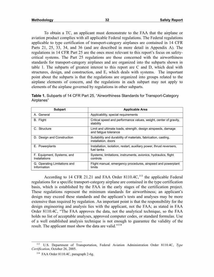
Methodology 32 Safety Report
To obtain a TC, an applicant must demonstrate to the FAA that the airplane oraviation product complies with all applicable Federal regulations. The Federal regulationsapplicable to type certification of transport-category airplanes are contained in 14 CFRParts 21, 25, 33, 34, and 36 (and are described in more detail in Appendix A). Theregulations in 14 CFR Part 25 are the ones most relevant to this report’s focus on safety-critical systems. The Part 25 regulations are those concerned with the airworthinessstandards for transport-category airplanes and are organized into the subparts shown intable 1. The subparts of greatest interest to this report are C and D, which deal withstructures, design, and construction, and E, which deals with systems. The importantpoint about the subparts is that the regulations are organized into groups related to theairplane elements of concern, and the regulations in each subpart may not apply toelements of the airplane governed by regulations in other subparts.
Table 1. Subparts of 14 CFR Part 25, “Airworthiness Standards for Transport-Category Airplanes”
According to 14 CFR 21.21 and FAA Order 8110.4C,113 the applicable Federalregulations for a specific transport-category airplane are contained in the type certificationbasis, which is established by the FAA in the early stages of the certification project.These regulations represent the minimum standards for airworthiness; an applicant’sdesign may exceed these standards and the applicant’s tests and analyses may be moreextensive than required by regulation. An important point is that the responsibility for thedesign engineering and analysis lies with the applicant, not the FAA; as stated in FAAOrder 8110.4C, “The FAA approves the data, not the analytical technique, so the FAAholds no list of acceptable analyses, approved computer codes, or standard formulas. Useof a well established analysis technique is not enough to guarantee the validity of theresult. The applicant must show the data are valid.”114
Subpart Applicable AreaA. General Applicability, special requirements
B. Flight Critical speed and performance values, weight, center of gravity, stability
C. Structure Limit and ultimate loads, strength, design airspeeds, damage and fatigue tolerance
D. Design and Construction Suitability and durability of materials, fabrication, casting, installation, doors
E. Powerplants Installation, isolation, restart, auxiliary power, thrust reversers, fuel tanks
F. Equipment, Systems, and Installations
Systems, limitations, instruments, avionics, hydraulics, flight controls
G. Operating Limitations and Information
Flight manual, emergency procedures, airspeed and powerplant limits
113 U.S. Department of Transportation, Federal Aviation Administration Order 8110.4C, TypeCertification, October 26, 2005.
114 FAA Order 8110.4C, paragraph 2-6g.

Methodology 33 Safety Report
The current type certification process, described in The FAA and Industry Guide toProduct Certification,115 is governed by procedures set forth in 14 CFR Part 21 and isdescribed in detail in FAA Orders 8100.5A and 8110.4C. Because the industry guide wasnot in effect during certification of any of the aircraft described in the four accidents,certain products required now were not required when the Boeing 737-300, 747-131,MD-83, and Airbus 300-605R investigated in the four accident case studies were certified.However, the five phases of the certification process described in the industry guide areconsistent with the processes that were required at that time, and represent the FAA’scurrent view of type certification. The deliverables and the time course of activities acrossthe five phases of type certification are shown in table 2, and are also described in moredetail in Appendix A. As highlighted in table 2, the type certification activities that mostclosely relate to the certification issues of concern are the certification basis, safetyassessments, and compliance demonstrations.
Establishing the Type Certification Basis
There is considerable incentive on the part of the applicant and the FAA to quicklyand accurately establish the type certification basis for an airplane because the applicableregulations determine the extent of the compliance effort. In addition, once thecertification basis is established, the set of regulations and standards will not be changedor new policy introduced unless a change is required to correct an unsafe condition.Establishing the type certification basis is an important milestone.
Federal regulations represent the minimum set of safety standards required for aTC and may not cover all potential safety issues. For example, the investigation ofAmerican Airlines flight 587 showed that certification standards did not exist for certainrudder pedal characteristics (for example, pedal sensitivity) or for assessing certain typesof pilot behavior with the rudder control system. None of the existing certificationregulations, other than the cautions about APC potential in advisory material, would haverequired the FAA to look more closely at the variable stop design in the A300-600 andA310 airplanes. Such situations, called special conditions, are provided for in theregulations and are described in more detail in Appendix A.
115 The industry guide was introduced in 1999 as part of a certification process improvement initiativeand revised in 2004. It emphasizes “establishing up-front a clear understanding of the needs andexpectations of both parties in the product certification process.” By applying the principles in theindustry guide, “the FAA and the Applicant can lay a foundation from which to build mutual trust,leadership, teamwork, and efficient business practices,” and enable them to “expedite certification ofproducts while focusing on safety significant issues.” The guide, implemented by FAA Notice 8110.80,The FAA and Industry Guide to Product Certification, February 26, 1999, is available at<http://www.faa.gov/aircraft/air_cert/design_approvals/>.

Methodology 34 Safety Report
Table 2. Product Timeline of Certification Process
Pre-Product Certification Phase I Phase II Phase III Phase IV Phase V
Partnership for Safety Plan
Project Specific Certification Plan
Type Certification Basis
Compliance Checklist
Type Design
Type Certificate Application
Certification Project Notification
Safety Assessments
Issue Papers
Special Conditions
Equivalent Safety Findings
Maintenance Review Board Report
Applicant Inspection, Ground Test, Flight Test Results
Compliance Demonstrations
Conformity Inspection Results
Type Inspection Authorization
Type Inspection Report: Ground
Type Inspection Report: Flight
Flight Manual
Instructions for Continued Airworthiness
Type Certificate
Compliance Summary Document
Certificate Management Plan

Methodology 35 Safety Report
An applicant can use an existing certification basis to substantially reduce the costsof compliance by showing that the type design being presented for approval is derivedfrom a previously certified airplane. These derivative designs, or “changed products,”116
allow applicants to propose changes to type designs of previously certified airplanes andretain the original TC. The FAA will approve changes to the original TC if they find thatthe changes are not significant. If the FAA finds that a proposed change is significant (asdefined by 14 CFR 21.101117), the applicant must establish a new certification basis.Further, if the changes incorporate new or novel features that are not covered byregulation, the certification basis may also include special conditions, as discussed inAppendix A.
For applicants, the advantages of a derivative design are twofold. First, theapplicant can save considerable time and money by using the results of the analyses, tests,and inspections conducted during the original type certification process to demonstratecompliance. Second, the regulations that apply to the derivative design are those that werein effect on the date of the original TC, not the date of the application for the new TC.Although the FAA encourages applicants to update the certification basis with anychanges to requirements issued after the original TC was approved, those updates are notrequired.
Approval of a derivative design may allow design deficiencies introduced with theoriginal TC to be carried over into subsequent models, as indicated by the USAir flight427 and Alaska Airlines flight 261 investigations. The Safety Board found that, for flight427, the FAA had stated its concerns about the Boeing 737 rudder servo valve designduring the original certification, and Boeing had also detected and corrected problemswith the design prototype. As for flight 261, the Board found that early experience withthe DC-9 jackscrew assembly wear rate prompted McDonnell Douglas to introduce theend play check procedure and wear limit. Because subsequent models of the 737 and theDC-9 were derivative designs, there was no requirement for these issues to be revisitedduring subsequent certification activities.
Demonstrating Compliance
Once the certification basis is established, the applicant demonstrates to the FAAthat the airplane design complies with Federal regulations. This is the type certificationphase that is the most time consuming and resource intensive and is most closely related to
116 Title 14 CFR 21.101, Changes to Type Certificates. Guidance for changed products is found in U.S.Department of Transportation, Federal Aviation Administration Advisory Circular, AC 21.101-1,Establishing the Certification Basis for Changed Aeronautical Products, April 28, 2003.
117 Title 14 CFR 21.101, paragraph b(1), states that a change is automatically considered significant if“(i) the general configuration or the principles of construction are not retained,” and “(ii) The assumptionsused for certification of the product to be changed do not remain valid.” In addition, 14 CFR 21.19, ChangesRequiring a New Certificate, indicates that a proposed design is significantly different from an existingdesign when the proposed changes are “so extensive that a substantially complete investigation ofcompliance with the applicable regulations is required.”

Methodology 36 Safety Report
the certification issues identified in the four accident case studies. The extent of theactivities associated with demonstrating compliance is shown in tables B1–B6 inAppendix B.
In its most basic form, demonstrating compliance is conducting either analyses ortests. Establishing the certification basis determines, to a large extent, which analyses andtests must be conducted, and the applicant can select from among a number of differentmethodologies. There are two basic types of compliance methods:118
• methods that demonstrate compliance through adherence to specific designand test criteria, and are typically deterministic, or
• methods that demonstrate compliance using probabilistic risk analysistechniques.
Many of the airworthiness standards spelled out in 14 CFR Part 25 are of the firsttype, requiring adherence to specific design criteria concerned with aerodynamicperformance, flight characteristics, and structural loads and strength requirements. Thoseregulations set specific design and/or performance criteria, and compliance isdemonstrated through engineering analysis, simulation, or ground and flight tests. Theevaluation of design features is assumed to be deterministic so that specific tolerances andlimits can be explicitly stated and analyzed. Failures are treated as deterministic, andanalyses and tests focus on the ability of the damaged structure or component to allowcontinued safe flight and operation.
In general, human factors considerations for certification are also specified inregulations as specific design criteria. For example, the workspace environment requiredby the flight crew is covered by 14 CFR 25.771–25.785, which specifies minimumstandards for occupant space, sightlines through windows, and cockpit control knobshape. Other regulations, such as 14 CFR D25.1, state in general terms human factorsrequirements related to minimum crew, workload, and functionality of aircraft systems.Some of the advisory material made available by the FAA provides very specific designguidance related to human factors, especially in the area of avionics. AC 25-11119 providesdetailed design criteria for displays, covering such topics as color-coding, symbology,clutter, and attention-capturing requirements. AC-25.1329 also provides detailed humanfactors design criteria for the autopilot and the requirements for assessing humaninteraction with the autopilot during flight tests. In general, compliance with human factorsrequirements is demonstrated by adherence to specific design criteria stated in regulationand is evaluated with mock-ups and simulators or during ground and flight tests.
118 A deterministic approach assumes the same result for a given set of initial conditions, while aprobabilistic (stochastic) approach assumes that randomness is present, even when given an identical set ofinitial conditions. Consequently, a probabilistic approach will always assume uncertainty in the result.Probabilistic methods can be viewed as inclusive of all deterministic events with a finite probability ofoccurrence.
119 FAA AC 25.11, Transport Category Airplane Electronic Display Systems (July 16, 1987).

Methodology 37 Safety Report
In contrast to specific design criteria stated in regulations, the second type ofmethod for determining compliance outlined in AC 25.1309-1A120 and governed by14 CFR 25.1309 treat failures as probabilistic and use a stochastic approach to assess theconsequences of system failures. The focus is on understanding the functional significanceof aircraft systems, determining the risks to safety of flight associated with a failurecondition, and using probability distributions to determine the frequency of occurrence ofa failure condition and its effects on overall system function. In the context of 14 CFR25.1309, the systems of interest are equipment and their installations. Guidance providedby AC 25.1309-1A specifically states that the regulation does not apply to Subparts B and Cof 14 CFR Part 25 that pertain to performance, flight characteristics, and structural loadand strength requirements.121
Fail-Safe Design Concept
Fundamental to the notion of safety-critical systems in certification is the fail-safedesign concept, which “considers the effects of failures and combinations of failures indefining a safe design.”122 The concept has a different meaning for structures than forsystems: fail-safe for structures is concerned with residual strength after sustainingdamage; fail-safe for systems is concerned with the functional implications of a failurecondition and its probability of occurrence. Although both concepts have the same goal—a safe design—the approaches to achieving that goal are different.
Fail-safe for structures is governed by 14 CFR 25.571 and the methods ofcompliance are outlined in AC 25.571-1C.123 In general, the structural components of anairplane (such as the airframe and wings) are designed such that “an evaluation of thestrength, detail design, and fabrication must show that catastrophic failure due to fatigue,corrosion, manufacturing defects, or accidental damage, will be avoided throughout theoperational life of the airplane.”124 However, after the 1988 Aloha Airlines flight 243accident,125 where 18 feet of the upper crown skin and structure separated from the fuselage,there has been a greater emphasis on damage tolerance. A damage tolerance evaluation ofstructure ensures that “should serious fatigue, corrosion, or accidental damage occur withinthe design service goal of the airplane, the remaining structure can withstand reasonableloads without failure or excessive structural deformation until the damage is detected.”126
120 The process is also described in SAE ARP4761.121 FAA AC 25.1309-1A, section 3.122 FAA AC 25.1309-1A, paragraph 5.123 FAA AC 25.571-1C, Damage Tolerance and Fatigue Evaluation of Structure, April 29, 1998.124 Title 14 CFR 25.571, section a.125 National Transportation Safety Board, Aloha Airlines, Flight 243, Boeing 737-200, N73711, near Maui,
Hawaii, April 28, 1988, Aviation Accident Report NTSB/AAR-89/03 (Washington, DC: NTSB, 1989).126 FAA AC 25.571-1C, Damage Tolerance and Fatigue Evaluation of Structure, section 6a.

Methodology 38 Safety Report
Fatigue safe-life was the predominant approach to evaluating structure before theshift to damage tolerance.127 The emphasis was empirical with the fatigue life of astructure defined as the number of bending cycles to failure. Once the fatigue life of astructure was determined, a safety factor was added to the estimated fatigue life to arriveat the safe-life of a structure. Damage tolerance emphasizes the physics of crack growthand is concerned with setting life limits (that is, inspection intervals that are based on thetime for a crack to grow or propagate).128 Regulations and advisory materials are veryspecific about the design features to be used to ensure damage tolerance, includingmultiple load path construction, crack stoppers, materials and stress levels that provide aslow rate of crack propagation, and designs that ensure detection before unacceptable orwidespread damage occurs.
A damage tolerance evaluation typically “consists of a deterministic evaluation ofthe design features”129 to ensure that airplane structural components are damage-tolerant.AC 25.571-1C identifies these components as principal structural elements (PSE),130 andmay include components of wings and empennage, fuselage, landing gear andattachments, and engine mounts. The evaluation identifies failures in terms of loadingconditions and possible damage and then uses structural tests or analyses to substantiatethat the design objective was achieved. The evaluation also generates data needed forinspection programs to ensure detection of damage during the operational life of thecomponent. Such evaluations and tests rely on engineering analyses—such as finiteelement analysis and structural analysis—and use quantitative approaches to establish theresponse of an aircraft component to various conditions of fatigue, corrosion,manufacturing defects, or accidental damage.
Fail-safe for systems treats failures differently. A failure, as defined in AC25.1309-1A and in Society of Automotive Engineers (SAE) ARP4761,131 is a loss offunction or a malfunction of a system, and differs from a failure mode, which is the way afailure in an item occurs. The focus is on understanding the functional significance ofaircraft systems, determining the risks to safety of flight associated with a failure condition,and using probability distributions to determine the frequency of occurrence of a failurecondition and its effects on overall system function. The purpose of the fail-safe designconcept for systems is to meet the following design objectives stated in 14 CFR 25.1309:
Airplane systems and associated components, considered separately and inrelation to other systems, must be designed so that—
127 U.S. Department of Transportation, Federal Aviation Administration, Damage Tolerance AssessmentHandbook, Vol. I: Introduction, Fracture Mechanics, Fatigue Crack Propagation (Cambridge, MA: VolpeNational Transportation Systems Center, 1993), Section 1.3.
128 FAA Damage Tolerance Assessment Handbook, Section 1.3.2.129 FAA AC 25.571-1C, section 6c.130 FAA AC 25.571-1C, section 6d, defines a PSA as “an element of structure that contributes
significantly to the carrying of flight, ground, or pressurization loads, and whose integrity is essential inmaintaining the overall structural integrity of the airplane” and lists examples.
131 SAE ARP4761.

Methodology 39 Safety Report
The occurrence of any failure condition which would prevent the continued safeflight and landing of the airplane is extremely improbable,132 and
The occurrence of any other failure condition which would reduce the capabilityof the airplane or the ability of the crew to cope with adverse operating conditionsis improbable.133
The regulation also specifies that warning information about the failure conditionbe provided to the crew so that they may take the appropriate corrective action. These twodesign objectives provide the basis for airplane certification standard practices andestablish the approach to be used to determine the relative importance (and severity) of asystem failure condition.
The two approaches to demonstrating compliance reveal a regulatory distinctionbetween aircraft systems and aircraft structures. Demonstrating compliance for aircraftstructures and aircraft performance typically uses deterministic methods that applypredetermined standards or criteria to assess the effects of fatigue, corrosion, andaerodynamic forces on aircraft components and aircraft strength capabilities. Forexample, 14 CFR 25.301 states that “strength requirements are specified in terms of limitloads (the maximum loads to be expected in service) and ultimate loads (limit loadsmultiplied by prescribed factors of safety),”134 and 14 CFR 25.303 states that “a factor ofsafety of 1.5 must be applied to the prescribed limit load which are considered externalloads on the structure.”135
Conversely, demonstrating compliance for systems uses probabilistic risk assessmentmethods that use qualitative and quantitative risk analysis techniques to assess the effectsof failures on system function and performance. According to 14 CFR 25.1309, the analysismust consider possible failure modes (including malfunctions and damage from externalsources), the probability of multiple failures and undetected failures, and the effects ofthose failures on the aircraft and its occupants. For example, 14 CFR 25.1333,“Instrument Systems,” states that—
the equipment, systems, and installations must be designed so that one display ofthe information essential to the safety of flight which is provided by theinstruments, including attitude, direction, airspeed, and altitude will remainavailable to the pilots, without additional crewmember action, after any singlefailure or combination of failures that is not shown to be extremely improbable.136
132 FAA AC 25.1309-1A, paragraph 10b, defines extremely improbable failure conditions as thosehaving a probability on the order of 1x10⁻⁹ or less (1 in one billion).
133 FAA AC 25.1309-1A, paragraph 10b, defines improbable failure conditions as those having aprobability on the order of 1x10⁻⁵ or less (1 in 100,000), but greater than on the order of 1x10⁻⁹.
134 Title 14 CFR 25.301, section a.135 Title 14 CFR 25.303.136 Title 14 CFR 25.1333, section b.

Methodology 40 Safety Report
Both approaches for demonstrating compliance have their advantages. The use ofengineering analysis and tests has a long regulatory history that has produced designcriteria developed over decades of flight experience. The design criteria in regulationsevolve, changing as the need arises and as experience is gained with specific types ofmaterials, components, and design features. Consequently, in certain areas of airplanedesign, the knowledge required to evaluate structures and components is well established.
A difficulty arises when the distinction between structure and systems is not clear,as in the case of the Alaska Airlines flight 261 MD-83 jackscrew assembly. During thepublic hearing for that accident, the FAA acknowledged that the jackscrew assembly hadboth structural and systems elements and therefore required compliance with different setsof regulations. The distinction was also used to justify an approach to demonstratingcompliance where the kinds of risk analysis outlined in AC 25.1309-1A would not apply.Consequently, the notion of assessing higher-level airplane system function based onlower-level component failure modes (for example, the loss of threads in the acme nut andscrew) was not required by regulation. Although new policy outlined in ANM-03-117-10places greater emphasis on a systems approach to flight-critical systems, the criteria foridentifying those components apply only to airplane systems and associated non-structuralcomponents.137 Furthermore, none of the regulations, including 14 CFR 25.1309 (and theconcomitant material in AC 25.1309-1A), explicitly address human error or the potentialrisks associated with crew interaction with airplane systems.
Conducting Safety Assessments
The risks to systems that are critical to safe flight and operation are evaluated intype certification during safety assessments. Safety assessments are the primary means bywhich the certification process identifies failure conditions, evaluates the potentialseverity of those failures, and determines their likelihood of occurrence. The safetyassessment process is outlined in AC 25.1309-1A, described in detail in SAEguidelines,138 and summarized in Appendix A of this report. All safety assessments areconducted by the applicant and are reviewed and accepted by the FAA.
A system is deemed critical if its failure would prevent the continued safe flightand landing of the airplane, or if it would reduce the capability of the airplane or the abilityof the crew to cope with adverse operating conditions. AC 25.1309-1A establishes anapproach that uses risk and hazard analysis to identify safety-critical systems. Theemphasis in the analysis is on identification of a failure condition, not a failed component,and on the functional effects of the failure (or failures) on the airplane and its occupants.This point bears repeating: the criticality of a failure condition—not the criticality of afaulty component—will determine if a system is safety critical.
137 FAA Memorandum ANM-03-117-10, p. 2.138 SAE ARP4761.

Methodology 41 Safety Report
For example, a jammed elevator caused by a broken linkage may not be a threat toflight safety unless the fault (the broken linkage) results in a failure condition (an airplaneattitude caused by the jammed elevator) that adversely affects the functional ability of theairplane to fly or land or the crew’s ability to maintain control. Consequently, thecriticality of a system becomes evident through the assessment of risk during safetyassessments and is based on the adverse effect on overall system function. As previouslydiscussed, safety assessments exclude consideration of failures that pertain toperformance, flight characteristics, and structural load and strength requirements.
The FAA is developing new guidance policy139 to clarify the use of risk assessmenttechniques in safety assessments and in the identification of flight-critical systemcomponents. According to that policy, the upcoming revision to AC 25.1309-1A includesfive severity classes: no safety effect, and minor, major, hazardous, and catastrophiceffects.140 A component is critical, states the policy, if a single failure results in ahazardous or catastrophic failure condition; if two failures result in a hazardous failurecondition or a combination of three failures results in a catastrophic failure condition; orall components contribute to a significant latent failure.141 The differences among theclasses are associated with effects on the airplane, effects on occupants and crew, and thequalitative and quantitative estimates of failure condition probability. The choice offunctions and failure conditions provides the foundation for all assessment of risks tosystems. Poor choices can lead to incomplete analyses and incorrect classification offailure condition severity. As a result, potentially dangerous failure conditions can remainundetected, especially if the assumptions underlying the analysis do not adequately reflectoperational scenarios and service history. The importance of a comprehensive, systematicprocess for identifying failure conditions was evident when the FAA’s ETEB review of theBoeing 737 rudder system, conducted after the USAir flight 427 investigation, identifiedmultiple failure conditions that had not been considered in the original type certificationprocess.
Safety assessments do not begin with a pre-determined set of safety-criticalsystems, but must identify potential hazards through analysis. Safety assessments proceedin a stepwise, data-driven fashion, starting with systems at the functional level, and addingmore specific design and implementation detail to address specific hazards, the potentialeffects of those hazards on the airplane and occupants, and possible solutions. Theprobability of a failure and the level of hazard classification are then used to determine thelevel of detail in an analysis for a particular system and its corresponding equipment.Thus, the final definition and characterization of a safety-critical system is the result of theanalyses conducted during a safety assessment.
Analytic and qualitative methods used in safety assessments include functionalhazard assessments, preliminary system safety assessments, preliminary hazard analyses,and system safety assessments. Methods may incorporate specific techniques, such as
139 FAA Memorandum ANM-03-117-10.140 FAA ANM-03-117-10, App. 2, Sec. 3.141 FAA ANM-03-117-10, page 3.

Methodology 42 Safety Report
fault tree analyses, failure modes and effects analyses, failure modes and effectssummaries, dependence diagrams, and Markov analyses. The techniques can becharacterized as providing either a top-down or bottom-up analysis of a design. Atop-down analysis, using functional hazard assessments and preliminary system safetyassessments, begins with high-level functional descriptions and design objectives andproduces a high-level description of the system architecture and associated failure conditionsand a classification of failure severity. Functions are defined and, once the system design isfinalized, failures are mapped to specific system components. A bottom-up analysis—usingfailure modes and effects analysis, for example—typically begins with a single failurecondition at the lowest level of a system. The purpose of a bottom-up analysis is todetermine how a failure condition at one level affects the system at the next higher level.This analysis usually begins with basic components and component data and builds uponthose data to conduct the requisite levels of analysis. The challenge for the analyst is toensure that the systems and failure conditions identified in a bottom-up analysis arereconciled with the functions and functional failures identified in the top-down analysis.142
Issue papers are another means by which the FAA can recommend additional ormore comprehensive safety assessments. In general, issue papers are used by the FAA toidentify and resolve any significant certification issue or problem that arises (the processfor generating issue papers and resolving the issues in them is discussed in Appendix A).What constitutes a significant issue is defined in FAA Order 8110.4C and can include newtechnology or novel design, the certification basis and means of compliance,environmental considerations, unsafe conditions, and special conditions. Issue papers indraft form are “prepared by government employees for use in effecting projectmanagement containing opinions, advice, deliberations and recommendations made in thecourse of developing official action by the government”143 and are exempt from publicdisclosure. Once issue papers are approved by the appropriate FAA directorate, they maybe available for public release.
The USAir flight 427 investigation provides an example of how an issue paper isused. In 1996, the FAA developed an issue paper to address flight control jams in thecertification of Boeing 737-600, -700, and -800 series airplanes. In that issue paper, theFAA defined “normally encountered roll/yaw control positions” and outlinedrequirements for compliance of the -600, -700, and -800 series airplanes using the controlpositions and scenarios defined by Boeing. One of the requirements was that normalroll/yaw control positions would be those required to counteract rudder jams duringnormal approach and landing configurations. The FAA used the issue paper to define both“normal” control positions and the scenarios for demonstrating compliance. The USAirflight 427 investigation found (and confirmed by the FAA’s CDR team in 1995) that thecontrol positions and scenarios defined in the issue paper did not sufficiently characterizeall of the situations that might be encountered in normal operations.
142 See FAA AC 25.1309-1A and SAE ARP4761.143 FAA Order 8110.4C, Appendix 12, paragraph 3c.

Methodology 43 Safety Report
The primary advantage of an issue paper is that one can be proposed at any time inthe certification process up to issuance of the TC (as shown in table 2). An issue paper istherefore a powerful tool for the government in alerting project management—both theFAA’s and the applicant’s—of the need to address a specific certification issue and is mostcommonly used in safety assessments to require additional or more comprehensiveanalyses. An important point is that issue papers, which are considered to be draftmaterial, are not part of the official certification project file and are therefore exempt frompublic disclosure. Thus, there is no requirement that issue papers be maintained as part ofthe official documentation for the airplane’s TC.
Post-Certification Processes
Issuing the TC marks the end of the type certification process and the beginning ofthe transition to production and air carrier operations. The Instructions for ContinuedAirworthiness (ICA),144 which represent the basic initial maintenance plan for theairplane, are an important component of the TC for air carrier operations. The ICA is animportant document because it conveys to operators and maintainers the manufacturer’sassumptions concerning requirements for preserving the airworthiness of an airplane andits components while in service.
The ICA is required by regulation to have two parts: the airplane maintenancemanual and the maintenance instructions.145 The airplane maintenance manual describesthe airplane and its components, component operation, and necessary maintenance andpreventive maintenance. Also included is any servicing information that—
covers details regarding servicing points, capacities of tanks, reservoirs, types offluids to be used, pressures applicable to the various systems, location of accesspanels for inspection and servicing, locations of lubrication points, lubricants tobe used, equipment required for servicing, tow instructions and limitations,mooring, jacking, and leveling information.146
Maintenance instructions provide the scheduling information for all airplanemaintenance. The MRB Report using the MSG-3 process, described under ProjectSpecific Certification Plan, is part of the maintenance instructions. These instructions areespecially important in that they specify the applicant’s recommendations for overhaulperiods and provide cross-references to airworthiness limitations, troubleshootinginformation, requirements for removing and ordering the removal of parts, and proceduresfor testing components. These are the instructions that McDonnell Douglas and Boeingprovided to Alaska Airlines stating the recommended lubrication and inspection intervalsfor the MD-80 jackscrew assembly.
144 Title 14 CFR 21.50b.145 Title 14 CFR H25.3.146 Title 14 CFR H25.3, paragraph a-4.

Methodology 44 Safety Report
In addition to establishing the requirements for continued airworthiness andoperator oversight, other post-certification activities concentrate on documenting thecertification process and establishing plans for managing the certificate. Details of thesepost-certification activities are provided in Appendix A, but are summarized here.
Several products are used to document the certification process. The CertificationSummary Report is “an executive summary containing high-level descriptions of majorissues and their resolution. The report should be used as a means for retaining corporateknowledge and lessons learned that could be beneficial for future type certificationprojects involving the same or similar type design.”147 The summary is not intended to becomprehensive, but focuses on lessons learned, areas for process improvement, andsignificant technology issues or novel design features. The ACO also prepares andmaintains a project file that contains only those documents showing a decision or actionby the FAA and copies of all of the major certification products.148
Provisions are made during post-certification to ensure that continued airworthinessissues will be handled after the aircraft is in service. To that end, a certificate managementplan and a continued airworthiness plan are the final products of the certification process. Aspart of this process, specific provisions are made for in-depth post-certification reviews ofpotentially unsafe design features or products. Called special certification reviews (SCRs),these reviews are a way for the FAA “to evaluate the type certification project andpotentially unsafe design features on previously approved products.” An SCR may beinitiated by the accountable directorate or “as service experience dictates.”149 Whenconcerned with compliance, an SCR may explore every aspect of the safety problem,including the applicant’s original certification data, inspection of prototype and productionarticles, and “the adequacy of the applicable regulations and policy material.”150
Other mechanisms are also in place to identify problems encountered duringoperations and maintenance that may lead to FAA oversight action. The FAA’s AirTransportation Oversight System (ATOS) was implemented in 1998 to enhance the FlightStandards air carrier surveillance requirement. According to the FAA, the ATOS “processassesses the safety of air carrier operating systems using system safety principles, safetyattributes, risk management, and structured system engineering practices.”151 The purposeof ATOS is to put in place a Part 121 air carrier surveillance program under thesupervision of the FAA’s Principal Inspectors and Certificate Management Team (CMT).FAA guidance states, “ATOS surveillance assesses an air carrier against establishedperformance measures in relation to specific regulatory requirements and safety attributesfor each element of an air carrier’s systems.”152
147 FAA Order 8110.4C, paragraph 2-7a(1).148 For a complete list, see FAA Order 8110.4C, appendix 10, figure 1.149 FAA Order 8110.4C, paragraph 2-7e(1a).150 FAA Order 8110.4C, paragraph 2-7(1f).151 U.S. Department of Transportation, Federal Aviation Administration Order 8400.10, Air
Transportation Operations Inspector’s Handbook, April 6, 2005, Appendix 6, Section 2, paragraph 122.152 FAA Order 8400.10, Appendix 6, Section 2, paragraph 125.

Methodology 45 Safety Report
The ATOS process focuses on risk identification, assessment, and management,and includes a number of environmental and operational risk indicators. Surveillance dataare gathered and contained in databases and are analyzed using a variety of qualitative andquantitative risk management and hazard analysis techniques. The initial phase of ATOSimplementation began with 10 major air carriers including American Airlines and AlaskaAirlines. A General Accounting Office (GAO) report on ATOS in 1999 was generallyfavorable, but pointed out a number of critical areas for improvement, including inspectortraining and data requirements for effective analysis. GAO recommended that the FAA notexpand the ATOS program beyond the initial 10 air carriers until the problems identified inthe report were corrected. According to congressional testimony given by the FAA’sassociate administrator for regulation and certification in 2002, ATOS was fullyimplemented for the original 10 air carriers, and many improvements had been made toATOS since its inception. The associate administrator went on to state that a new version ofATOS was anticipated in 2004 that would further enhance risk assessment capabilities.153 InApril 2005, major revisions were made to ATOS policies and procedures that allow “CMTsto apply ATOS policies and procedures more consistently for all air carriers.”154
Other programs are also in place to support certificate management and continuedairworthiness issues. The FAA’s Aircraft Certification Evaluation System (ACSEP)155 isconcerned with ensuring that the holders of a type production approval or delegatedfacilities meet the requirements set forth in Federal regulations. ACSEP uses FAAengineering, flight test, and manufacturing inspection personnel to evaluate control ofFAA-approved type design, production activities, and design approval systems.Consequently, the program focuses oversight and inspection on manufacturers, partsuppliers, and delegated facilities and their adherence to Federal regulations. Once thesecontinued airworthiness and certificate management plans are put in place, the airplane isready for service in air carrier operations.
In summary, the TC (and its accompanying ICA) and other post-certificationactivities establish the transition from certification to operations and provide the basis forcontinued airworthiness and operations oversight.
153 Testimony of Nicholas A. Sabatini, Associate Administrator for Regulation and Certification,Federal Aviation Administration, before the U.S. Congress Committee on Transportation and Infrastructure,Subcommittee on Aviation, on FAA Oversight of Passenger Aircraft Maintenance, April 11, 2002.
154 FAA Order 8400.10, Appendix 6, Section 1, paragraph 104.155 U.S. Department of Transportation, Federal Aviation Administration Order 8100.7C, Aircraft
Certification Systems Evaluation Program, October 12, 2005.

46 Safety Report
Other Efforts to Study Certification
Certification has been the focus of several other recent studies: the FAACommercial Airplane Certification Process Study; the RTCA Task Force 4 onCertification, and the National Research Council (NRC) assessment of the FAA AircraftCertification Service’s safety management process. Many of the certification issuesrevealed in the Safety Board’s investigations were also of interest to these groups. Ratherthan provide a comprehensive review of the three studies, this report highlights the issuesin these studies that parallel the issues in this report.
FAA Commercial Airplane Certification Process Study
The FAA organized a joint government/industry certification study thatspecifically addressed safety-related processes. The Commercial Airplane CertificationProcess Study (CPS) was initiated in 2001 to assess the effectiveness of the Agency’scertification process throughout the life cycle of an aircraft. CPS used historical reportsand accident data to identify critical certification issues. The list of accidents used by CPSto identify issues significantly overlaps the accidents shown in Appendix C. CPS results,published in 2002, were a series of findings that highlighted the need to identify and trackcritical systems, conduct airplane-level assessments, improve communication betweencertification and operations, and better use lessons learned in design, operations, andmaintenance.
CPS reported that it conducted a process analysis of certification to identifyprocess improvement opportunities, but the final report did not document themethodology used to conduct the analysis. The report referred to both top-down andbottom-up analytic approaches; however, much of the analysis presented in the final reportappeared to be based on a review of an accident list and on information provided bygovernment and industry representatives. Overall, the focus of the report was high leveland primarily concerned with issues related to communications and information interfacesbetween certification, operations, and maintenance.
The CPS team noted that critical safety systems are the product of both the designand the safety assurance decision-making process accomplished during certification. Thecriticality of a system becomes evident when design assumptions and functionalinteractions among safety-critical features are explored. The CPS team also indicated thatcritical systems are not consistently identified during design and certification, and theassumptions underlying the risk analysis associated with those systems are rarely revisitedonce the aircraft is placed in service. As a result, the CPS team is considering mechanismsfor identifying and tracking critical systems throughout the life cycle of the airplane.

Other Efforts 47 Safety Report
Although the team acknowledged the importance of safety assessments in theidentification of safety-critical systems and was considering airplane-level risk and hazardanalysis as a way to address overall aircraft system performance, neither the final reportnor the strategic plan recommended adoption of a comprehensive systems engineeringapproach in certification. Furthermore, CPS did not discuss a 1998 NRC recommendationfor a comprehensive safety assessment process emphasizing the principles of riskmanagement and the use of risk analysis tools. The recommendation was a result of astudy conducted by the NRC as a result of an FAA request to study AIR’s safetymanagement process. (The NRC study is discussed in more detail in the followingsection.) In fact, the CPS final report did not mention the NRC study.
The life cycle of a product was discussed in CPS and characterized in its StrategicPlan in terms of various life cycle “themes,” including critical safety systems, datamanagement, human factors, and operator oversight. The CPS final report stated that “aswith all design assurance processes, for the safety assessment to be effective, it must tracethrough the entire life cycle of the product.”156 CPS pointed out in its final report the needfor better communication between certification and operations and maintenance, andmade recommendations to change or clarify regulations, policy, and guidance. But thereport did not recommend adoption of a life-cycle engineering approach where tracking,monitoring, and continuously assessing critical systems would be inherent activities andwould require the flow of information among the various parties involved in certification,operations, and maintenance.
CPS also identified human factors as one of nine major themes and concluded that“design techniques, safety assessments, and regulations do not adequately address thesubject of human error in design or in operations and maintenance.”157 The report went onto recommend that the processes used to incorporate human behavior and performance insafety assessments during certification must be improved, but provided no specificrecommendations on how such improvements should be made.
RTCA Task Force 4 on Certification
Begun in 1998, the RTCA study on certification focused on communications,navigation, surveillance (CNS), and air traffic management (ATM) systems. RTCA, Inc.,is a private, nonprofit corporation contracted by the Federal government to addressrequirements and technical concepts for aviation. Many RTCA activities for the FAAconcern developing standards and technical advisory documents (for example, RTCA/DO178B for software systems). The RTCA Task Force was organized in response to theFAA’s focus on modernization of the National Airspace System (NAS) and its initiativesto implement free flight. The Task Force was organized into four working groups (WGs);
156 U.S. Department of Transportation, Federal Aviation Administration, Commercial AirplaneCertification Process Study (Washington, DC: Federal Aviation Administration, March 2002), p. 7.
157 FAA Commercial Airplane Certification Process Study, p. 9.

Other Efforts 48 Safety Report
one of the four—WG4—was concerned with the certification process and servicesprovided by the FAA and international certification authorities.
Although the Task Force did not specifically address aircraft, its treatment of theNAS did consider how the FAA’s certification process dealt with new products andequipment. One of the major findings of the Task Force was that the overall, end-to-endsystem was not being properly addressed, a finding consistent with this report’sconclusion of the lack of a comprehensive systems engineering approach. In its finalreport, the Task Force stated that “safety and performance assessments are done on theelements of a system, but without the overall understanding of the relationship ofindividual elements’ responsibilities and contribution to performance and safety.”158 TheTask Force also pointed out that no person or organization is responsible for ensuring thatan overall system perspective is included during certification.
Task Force findings again supported the conclusion that an overall systemsengineering approach to certification was required, but did not make specificrecommendations about the application of systems engineering or life cycle engineeringprinciples to certification.
National Research Council Report on Improving Continued Airworthiness
The FAA asked the NRC to evaluate the safety assessment process used by theAIR. One goal of the NRC study focused on AIR’s safety management process and theability of that organization to identify and manage risk. The final report was published in1998 with recommendations.
The NRC identified the need for a comprehensive safety assessment process thatwould allow the FAA to take corrective action based on accident, incident, and operationaldata. Such a process could be put in place, concluded the committee, by emphasizing theprinciples of risk management and the use of risk analysis tools. In addition to puttingtogether a comprehensive risk management program, the committee believed that theFAA’s failure data analysis efforts could be improved “by relying more on scientific andengineering information to supplement operational and maintenance data.”159 The NRCalso found FAA’s data collection and analysis to be fragmented and recommended that theFAA develop a process to facilitate communication and coordination between Certificationand Flight Standards. Such an exchange of continued airworthiness information, stated thecommittee, was necessary for an effective safety assessment program.160
158 Final Report of RTCA Task Force 4, Certification (Washington, DC: RTCA, Inc., 1999), p. 69. 159 National Research Council, Improving the Continued Airworthiness of Civil Aircraft (Washington,
DC: National Academy Press, 1998), p.35160 Improving the Continued Airworthiness of Civil Aircraft, pp. 45-46.

Other Efforts 49 Safety Report
Both the NRC study and the Safety Board investigation of TWA flight 800 wereconcerned about the effectiveness of risk analysis and risk management methods, but fordifferent reasons. Whereas the NRC study believed, in general, that the FAA needed toimprove its risk assessment process, the Board stated a concern “that undue reliance isbeing placed on such analyses as proof that ignition sources have been precluded” and thepossibility that “unrealistic or otherwise flawed data can be used to develop fault trees.”161
The Board’s concerns were the result of a review by NASA of the risk analysis provided byBoeing during the investigation to evaluate the potential risk of explosion in the centerwing fuel tank. The lack of good data, adequate probability estimates, and validation of themethodology were all central to the Safety Board’s concerns about the validity of the riskassessments, and led the Board to conclude that FMEAs and fault tree analyses “should notbe relied upon as the sole means of demonstrating that an airplane’s fuel tank system is notlikely to experience a catastrophic failure.”162
FAA’s ability to continuously assess safety-critical systems in light of servicehistory and lessons learned was another area where considerable agreement occurredbetween the NRC and the Safety Board. In the USAir flight 427 investigation, evidence ofrudder anomalies in a number of incidents indicated a potential problem with the ruddersystem. In Alaska Airlines flight 261, changes to lubrication and inspection intervals weremade by the air carrier without sufficient consideration of the adverse effects on thejackscrew assembly. The history of rudder use by pilots in upset recovery, revealed duringthe investigation of American Airlines 587 and in the NASA special study of in-flightupsets, indicated that the original assumptions about pilot use of rudder were perhaps notvalid. TWA flight 800, Alaska Airlines flight 261, and American Airlines flight 587highlight the NRC conclusion that a more comprehensive risk assessment program for allaspects of aircraft certification and continued airworthiness is needed.
161 NTSB/AAR-00/03, p. 295.162 NTSB/AAR-00/03, p. 297.

50 Safety Report
Analysis
As discussed in the Introduction, the Safety Board has two concerns about typecertification: how risks to safety-critical systems are identified, assessed, and documentedduring the certification process, and how risks to safety-critical systems are assessedthroughout the life of the airplane. The first concern most closely relates to thecertification phase in which an applicant demonstrates compliance with Federalregulations. The second concern relates to post-certification activities and the interactionsamong certification, operations, and maintenance.
Identifying and Assessing Safety-Critical Systems
The FAA uses the safety assessment process to identify and evaluate safety-criticalfunctions in systems. The methods and techniques used in safety assessments are wellestablished and the process can be effective in identifying and evaluating hazards to safetyof flight. Through the safety assessment process, a system is deemed critical if its failurewould prevent the continued safe flight and landing of the airplane, or if its failure wouldreduce the capability of the airplane or the ability of the crew to cope with adverseoperating conditions. The process, as previously discussed, uses risk and hazard analysisto identify failure conditions, evaluate the potential severity of those failures, anddetermine their likelihood of occurrence. Safety assessments do not begin with a pre-determined set of safety-critical systems, but rather, with a set of criteria for determiningthe criticality of systems. The analysis emphasizes the identification of a failure condition,not a failed component, and the functional effects of the failure (or failures) on theairplane and its occupants. Safety-critical systems are defined in this report using thecriteria set forth in FAA guidance material for identifying and evaluating failureconditions that are classified as major or catastrophic. The Safety Board concludes that thesafety assessment process is an effective way to identify safety-critical systems duringtype certification. However, the Board believes that the process can be improved in anumber of ways.
First, based on an evaluation of failure conditions in the aircraft, safetyassessments can produce a list of safety-critical systems associated with those failures thatcan accompany the TC. FAA’s Certification Process Study recognized that the “processesfor identification of safety critical features of the airplane do not insure that futurealterations, maintenance, repairs, or changes to operational procedures can be made withcognizance of those safety features.”163 Had such a list been available to Alaska Airlines,it would have provided for access to certification analysis information about the designintegrity of the jackscrew assembly for the purpose of deciding about changes tolubrication and inspection intervals. The Safety Board concludes that the lack of a
163 FAA Commercial Airplane Certification Process Study, p. 27.

Analysis 51 Safety Report
requirement to prepare a list of safety-critical systems during the type certification of atransport-category airplane compromises the ongoing assessment of these systems. Sucha list of safety-critical systems could be identified based on the outcomes of the safetyassessment process.
Second, the FARs do not explicitly require that the results of safety assessments bepreserved in the official type certification project file for ongoing safety analysis. AC25.1309-1A specifies that safety assessment results be included with the analysispresented to the FAA, and the Certification Summary Report described in Order 8110.4C“is a high-level description of major issues and their resolution”164 that may not capturethe details required to effectively evaluate service history and operational experience. Inaddition, not all projects require a summary report. Consequently, the rationale, analysismethods, failure scenarios, supporting evidence, and associated issue papers used toidentify and assess safety-critical systems may not be available for future review andconsideration by the FAA, the manufacturer, or the operators. For example, suchmaterials may have proved useful in assessing the assumptions underlying the US Airflight 427 Boeing 737 servo valve during certification activities for subsequent derivativedesigns, especially in light of the airplane’s rudder-related incident history.
Finally, issue papers that are used to specify the scope and depth of a safetyassessment are not necessarily available for future review and consideration. Aspreviously discussed, the FAA uses issue papers to identify and resolve any significantcertification issue or problem that arises during the certification process. Significantly, theFAA, not the applicant, generates issue papers as a means to identify potentially unsafeconditions and systems that may require further scrutiny. For example, when newtechnology or novel designs are proposed for certification, an issue paper can be used torecommend that applicants consider more detailed testing or analysis to determine theeffects of potential failure conditions. Issue papers do not, however, necessarily becomepart of the official type certification project file; according to the FAA, they are exemptfrom public disclosure in draft form, and are retained only at the discretion of the ACOManager.
The Safety Board concludes that systems are identified as safety critical through thesafety assessment process, but the results of that process—including the rationale, analysismethods, failure scenarios, supporting evidence, and associated issue papers used toidentify and assess safety-critical systems—are not consistently documented for futurereview and consideration. Therefore, the Safety Board recommends that the FAA compile alist of safety-critical systems derived from the safety assessment process for each typecertification project, and place in the official type certification project file thedocumentation for the rationale, analysis methods, failure scenarios, supporting evidence,and associated issue papers used to identify and assess safety-critical systems. 165
164 FAA Order 8110.4C, paragraph 2-7a(1).165 The project file is described in the Data Retention section of FAA Order 8110.4C, paragraph 2-7f.

Analysis 52 Safety Report
Excluding Structural Failures from Safety Assessments
Excluding structural failures from safety assessments occurs because Federalregulations specify different methods of compliance for systems and for structures.Although the methods for demonstrating compliance are well founded, this distinction canhinder the identification of safety-critical systems and the application of the fail-safedesign concept. For instance, fail-safe, as it pertains to systems, applies only to themitigation of failure conditions covered by 14 CFR 25.1309. Fail-safe, as it pertains tostructures, “is the attribute…that permits [the structure] to retain its required residualstrength for a period of unrepaired use after the failure or partial failure of a principalstructural element.”166 The performance of structure is based on the number ofoperational events (for example, flights, landings, and flight hours) required to reduce thestrength of a structural element below its design ultimate value due to cracking.167 Theguidance provided by AC 25.1309-1A specifically states that 14 CFR 25.1309 does notapply to 14 CFR Part 25, Subparts B and C, which pertain to performance, flightcharacteristics, and structural load and strength requirements.168 Consequently, structuralfailures are excluded from safety assessments. Although new policy outlined inANM-03-117-10 places greater emphasis on a systems approach to flight-critical systems,the criteria for identifying those components apply only to airplane systems and associatednon-structural components.169 The Safety Board found no provisions in existing typecertification regulations and advisory materials for considering the functional implicationsof structural failures in the assessment of safety-critical systems.
The problem created by excluding the functional implication of structural failuresfrom consideration was evident in the Alaska Airlines flight 261 investigation. The FAAused the distinction between structures and systems to explain during the public hearingwhy a safety assessment of the entire jackscrew assembly did not occur, either duringcertification of the DC-9 when regulations called for a fault analysis, or during subsequentcertification of MD-80 series airplanes covered by the more comprehensive requirementsof AC 25.1309-1A. In all cases, because the acme nut was not considered part of asystem, it was not required to comply with airplane systems certification requirements.170
The Safety Board concluded in the Alaska Airlines flight 261 report, however, that“catastrophic single-point failure modes should be prohibited in the design of all futureairplanes with horizontal stabilizer trim systems, regardless of whether any element of thatsystem is considered structure rather than system or is otherwise considered exempt fromcertification standards for systems.”171 A damage-tolerance approach to the design ofprincipal structural elements in transport-category airplanes recognizes that some failures,short of catastrophic, can occur. As a result of the analysis conducted for this report, the
166 FAA AC 25.571-1C, paragraph 3b.167 FAA AC 25.571-1C, paragraph 3c.168 FAA AC 25.1309-1A, section 3.169 FAA ANM-03-117-10, p. 2.170 Alaska Airlines flight 261, NTSB/AAR-02/01, p. 23.171 Alaska Airlines flight 261, NTSB/AAR-02/01, p. 180.

Analysis 53 Safety Report
Safety Board is concerned that the effect of structural failures on the performance ofrelated systems is not being considered in risk assessments for type certification.
Excluding Human Error from Safety Assessments
Human error is a major, recurring issue in most aviation accidents. The SafetyBoard has consistently cited personnel as the major cause or factor of accidents,exceeding the proportion of accidents related to aircraft or environmental causes by alarge margin. As previously mentioned, human factors considerations for certificationpurposes are specified in regulations as specific design criteria, and in a way similar tothe criteria found for airplane performance, structures, and flight characteristics.Furthermore, a human factors certification plan is advised, but not required. The mostrigorous evaluations of human/airplane system interaction occur as part of ground orflight tests using experienced test pilots. This phase of testing occurs late in thecertification process after most of the safety assessments are finished and the designfinalized.
Human error is referenced in 14 CFR 25.1309, but only in terms of the probabilitythat a failure will adversely affect the crew: “The airplane systems and associatedcomponents…must be designed so that…the occurrence of any other failure conditionwhich would reduce the capability of the airplane or the ability of the crew to cope withadverse operating conditions is improbable.”172 Title 14 CFR 25.1309 also addresses theeffect of warning information on crew response to a failure condition. Only implicitlydoes AC 25.1309 suggest the need to analyze the risks associated with human/airplanesystem interaction failures by considering the “effects on the crewmembers, such asincreases above their normal workload that would affect their ability to cope with adverseoperational or environmental conditions or subsequent failures.”173
Safety Board investigations have shown that the potential for human/airplanesystem interaction failures is increased when an airplane design contains complexities thatare difficult for people to discern in an operational context. The problem with a rudderpedal design that produces maximum rudder pedal travel at high speeds with only afraction of the travel available on the ground was evident to the Safety Board in itsinvestigation of American Airlines flight 587: “The first officer may have failed toperceive that his control wheel and rudder inputs were the cause of the airplane motion inpart because that motion may have appeared out of proportion to his pedal inputs.”174
Unlike other regulations pertaining to airplane structures, performance, andsystems, regulations pertaining to human performance do not provide specific guidanceabout appropriate compliance methods. FAA policy addresses human factors issues intransport-category airplane type certification in terms of procedural and workload
172 Title 14 CFR 25.1309 paragraph b(2).173 FAA AC 25.1309 paragraph 7b(2).174 American Airlines flight 587, NTSB/AAR-04/04, pp. 149-150.

Analysis 54 Safety Report
analyses and tests, and through mock-ups, simulators, and in-flight evaluations.175 Thefunctional implications of failures that could result from human interaction with airplanesystems and components are not analyzed in safety assessments. The Safety Board isconcerned that human interaction failures are not addressed in the assessment ofsafety-critical systems.
In contrast to commercial aviation, other Federal agencies (like the Department ofEnergy and DoD, for example) explicitly address human performance in design anddevelopment and incorporate human factors knowledge in risk and hazard analyses. TheNuclear Regulatory Commission pioneered the development and use of human reliabilityanalysis and the application of human error probabilities to tasks performed by humanoperators in nuclear power plant control rooms.176 As a result, the Nuclear RegulatoryCommission’s Handbook of Human Reliability Analysis has become one of the importantreferences for human reliability analysis. 177
Department of Defense Directive (DODD) 5000.1 calls for military systemsdevelopment to “apply human systems integration to optimize total system performance(hardware, software, and human), operational effectiveness, and suitability, survivability,safety, and affordability.”178 The policy directive concludes that this approach will ensuresafety especially when it is related to human-system interfaces.179 DoD MIL-STD-882D,Standard Practice for System Safety, outlines the methods and techniques to be used toconduct risk and hazard analyses (including human error analysis) and specifically liststhe kinds of human performance that define unacceptable safety-critical conditions.180
Additional guidance is provided in the Defense Acquisition Guidebook181 and in DoDHandbook, MIL-HDBK-46855a, Human Engineering Program Process and Procedures,which references the use of human performance reliability analysis as one way to identifyfactors that hinder reliable human performance in military systems.182 Both MIL-STD-882Dand MIL-HDBK-46855a are referenced in the guidance and in advisory materials for theFAA’s safety risk management program.
175 U.S. Department of Transportation, Federal Aviation Administration Memorandum ANM-99-2,Guidance for Reviewing Certification Plans to Address Human Factors for Certification of TransportAirplane Flight Decks (September 29, 1999).
176 Probabilistic risk assessment (PRA) is one form of risk analysis that, in its latest form, combinesevent trees that capture the sequence of events in a scenario with fault trees that allow the analysis of all thefactors contributing to failure events in the scenario.
177 A.D. Swain and H.E. Gutman, Handbook of Human Reliability Analysis with Emphasis on NuclearPower Plant Applications, NUREG/CR – 1278 (Washington, DC: U.S. Nuclear Regulatory Commission,1983).
178 DODD 5000.1, The Defense Acquisition System (May 12, 2003). paragraph E1.29.179 DODD 5000.1, paragraph E1.23.180 MIL-STD-882D, paragraph A.4.3.3.1.1.181 DODD 5000.1, Chapter 6.182 U.S. Department of Defense Handbook MIL-HDBK-46855A, Human Engineering Program Process
and Procedures (Washington, DC: May 17, 1999), paragraph 8.3.16.

Analysis 55 Safety Report
The extensive use of risk-based approaches to human performance by otherFederal agencies highlights the importance of human factors issues and the need tospecifically consider the risks to system performance associated with human behavior.The extensive procedural character of commercial aviation operations, the well-documented research on pilot behavior and performance, and the preponderance ofaviation accidents attributed to human error would appear to support the use of humanperformance analysis in the assessment of safety-critical systems.
While 14 CFR 25.1309 may be interpreted as implicitly including failuresassociated with human interaction with airplane systems and the types of structuralfailures discussed in the previous section, the Safety Board believes that the acceptedmethods of compliance described in related advisory materials do not require such failureconditions to be explicitly considered. The Board concludes that consideration ofstructural failure conditions and human/airplane system interaction failure conditions arenot required in the certification-related assessments of safety-critical systems, and theseexclusions limit the scope of the failure conditions considered during the safetyassessment process. The Board recommends that the FAA amend the advisory materialsassociated with 14 CFR 25.1309 to include consideration of structural failures andhuman/airplane system interaction failures in the assessment of safety-critical systems.
Monitoring and the Ongoing Assessment of Safety-Critical Systems
Once safety-critical systems have been identified, assessed, and documentedduring type certification, feedback mechanisms are needed to ensure that the underlyingassumptions made during design and certification are continuously assessed in light ofoperational experience, lessons learned, and new knowledge. These mechanisms requirecoordination between FAA organizations responsible for certification, continuedairworthiness, and operational oversight.
The importance of feedback in the ongoing assessment of safety-critical systemswas illustrated by the Alaska Airlines flight 261 accident investigation. The investigationfound that changes to maintenance practices and intervals were made without sufficientanalysis, justification, and consideration of design assumptions made during certification.As a result, the Safety Board recommended to the FAA that the maintenance proceduresand intervals for all critical aircraft components be reviewed to ensure a soundengineering justification, and that any extensions to those intervals “(1) take into accountassumptions made by the original designers, (2) are supported by adequate technical dataand analysis, and (3) include an appropriate safety margin that takes into account thepossibility of missed or inadequate accomplishment of the maintenance task.”183
Monitoring and tracking safety-critical systems was of particular concern to the Board,resulting in a recommendation to establish a program that would track and analyze
183 NTSB Safety Recommendation A-02-41; full text and status are shown in Appendix C.

Analysis 56 Safety Report
jackscrew wear and end play measurements by aircraft registration number and jackscrewassembly serial number, and to report those results to the FAA.184
USAir flight 427 and American Airlines flight 587 also illustrate how operationalexperience may indicate a need to reconsider assumptions made during certification. Withregard to USAir flight 427, the FAA was concerned about the rudder system duringcertification of the Boeing 737-100, and the history of rudder service difficultiesuncovered during the investigation led the Safety Board to conclude that those concernswere valid. Review of the 737 rudder system by the FAA’s ETEB also identified multiplefailure modes that had not been previously considered during certification. The history ofrudder use by pilots in upset recovery, revealed during the investigation of AmericanAirlines 587 and in the NASA special study of in-flight upsets, indicated that the originalassumptions about pilot use of rudder were perhaps not valid. CPS also recognized theneed to validate assumptions made during certification with respect to service experienceand added that “certification standards may not reflect the actual operatingenvironment.”185
USAir flight 427, Alaska Airlines flight 261, and American Airlines flight 587also provide evidence to support a number of the FAA’s CPS findings. CPS found that theprocesses for identifying safety-critical features of an airplane “do not ensure that futurealterations, maintenance, repairs, or changes to operational procedures can be made withcognizance of those safety features.”186 In addition, CPS found no reliable process forvalidating assumptions made in safety assessments in light of operational andmaintenance experience, and that operators may be unaware of those assumptions whenmaking operations and maintenance decisions. CPS also found that existing FAAprocesses do not capture “the lessons learned from specific experiences in airplane design,manufacturing, maintenance, and flight operations” or make them readily available.187
The Safety Board agrees with these findings and the need to revise the process to ensurethe ongoing assessment of safety-critical systems.
SAE ARP5150, Safety Assessment of Transport Airplanes in CommercialService,188 provides a process accepted by industry for ongoing assessment of safety-criticalsystems that would address Safety Board concerns and correct the deficiencies found byCPS. The practice outlined in SAE ARP5150 describes guidelines, methods, and tools forconducting ongoing safety assessments. The process has five general, ongoing, iterativesteps, which are summarized in table 3. Critical to the process is the identification andmonitoring of safety-related parameters that are used to identify significant safety eventsand to assess the risks of those events. SAE ARP5150 provides an example that starts witha set of parameters for step 1 (drawn from operators, manufacturers, and the FAA),continues with a set of potential significant safety events for consideration in step 2, and
184 NTSB Safety Recommendation A-02-45; full text and status are shown in Appendix C.185 FAA Commercial Airplane Certification Process Study, p. 18.186 FAA Commercial Airplane Certification Process Study, p. 27.187 FAA Commercial Airplane Certification Process Study, p. 50.188 SAE ARP5150.

Analysis 57 Safety Report
elaborates the risk assessment tools and techniques that can be used in step 3. Considerableemphasis is placed on the ongoing and iterative nature of the process. The document statesthat “to improve safety during the complete airplane life cycle, it is not sufficient to assessthe safety of the airplane only during its design phase” and that—
differences exist or can develop between the assumptions made during the designphase and how the airplanes are actually operated and maintained. For thesereasons, safety should be assessed also during the “In-Service” phase of theairplane life cycle. In order to do that, information must be collected, monitored,and analyzed.189
Table 3. Steps in the Ongoing Safety Assessment Process.
The Safety Board believes that the ongoing safety assessment process outlined inSAE ARP5150 can provide the basis for the continuous assessment of safety-criticalsystems throughout the life of a transport-category airplane. Properly implemented, theprocess provides the feedback mechanisms necessary to assess safety-critical systems inlight of operational experience, lessons learned, and new knowledge. In addition, anongoing safety assessment process can provide the basis for collecting service history andoperational data that can be used to validate assumptions made during certification,operations, and maintenance, and to prompt timely and comprehensive reviews ofpotential airworthiness problems. If such an approach is in place when questions ariseabout service experience (for example, the rudder anomalies uncovered in the USAirflight 427 investigation or the amount of rudder deflection in Airbus airplanes uncoveredin the American Airlines flight 903 investigation), a systematic evaluation and review ofdesign features, certification procedures, and operational and maintenance practices canoccur.
189 SAE ARP5150, p. 4.
Step Description1. Establish Monitor Parameters Determine the specific safety structure, objectives, and goals
for ongoing safety assessments. Establish the monitoring parameters and their values.
2. Monitor for Events A continuous process of looking for events of concern. Monitoring is based on the monitor parameters established in step 1.
3. Assess Event and Risk Initiated when an event is detected, includes assessment of the event sufficient to determine if the event is of concern and preliminary determination of risk for use in prioritizing action plan development. Scope and detail of risk assessment based on seriousness of event.
4. Develop Action Plan Establishes the correction or improvement to be made to design, operations, maintenance, or training.
5. Disposition Action Plan Implementation and evaluation of the action plan.

Analysis 58 Safety Report
The ongoing safety assessment process outlined in SAE ARP5150 is consistentwith existing provisions in certification regulations that allow reconsideration ofairworthiness issues after the airplane is placed in service. Special certification reviewscan be initiated to consider potentially unsafe design features of previously approvedproducts.190 An SCR is initiated by the accountable directorate, which has considerablediscretion in the use of evaluation procedures to ensure that “every significant aspect andramification of the potential safety problem in question” is thoroughly explored, includingthe “adequacy of the applicable regulations and policy materials.”191 Certificationregulations also provide for FAA fact-finding investigations in response to reports orallegations of certification basis noncompliance, which help the FAA decide what actionto take. The opportunity for reviews based on these types of triggering events can be partof an ongoing safety assessment program.
Finally, ongoing safety assessments could improve the FAA’s ability to evaluatederivative designs. In both the USAir flight 427 and the Alaska Airlines flight 261investigations, the Safety Board found that some issues raised during the originalcertification of the aircraft were not addressed during subsequent certification efforts.Once the TC was issued in 1967, questions raised by the FAA about the original Boeing737 rudder servo unit design were not revisited until the 1992 ground check incident andwere not adequately resolved until after the USAir flight 427 investigation was complete.Certification of the MD-83 involved in the Alaska Airlines flight 261 accident was basedon the original DC-9 TC issued in 1965. The jackscrew was treated as a derivative designand the potential latent problems associated with the original DC-9 design assumptionswere passed along to the MD-80. Despite subsequent extensions to MD-80 lubricationand inspection intervals requiring MRB review and acceptance, no questions were raisedabout the strength and wear-rate assumptions underlying the design of the jackscrewassembly and its maintenance requirements. Certification activities that accompany aderivative design could be treated as a critical event in the ongoing safety assessmentprocess and provide an opportunity to re-assess, if necessary, safety-critical systems.
The Safety Board concludes that the policy, practices, and procedures put in placefor continued airworthiness do not ensure that the underlying assumptions made duringdesign and type certification about safety-critical systems are assessed in light ofoperational experience, lessons learned, and new knowledge. The Board thereforerecommends that the FAA adopt SAE ARP 5150 into 14 Code of Federal RegulationsParts 21, 25, 33, and 121 to require a program for the monitoring and ongoing assessmentof safety-critical systems throughout the life cycle of the airplane. Safety-critical systemswill be identified as a result of A-06-36. Once in place, use this program to validate thatthe underlying assumptions made during design and type certification about safety-criticalsystems are consistent with operational experience, lessons learned, and new knowledge.
190 An example of an SCR is the one initiated by the FAA to investigate Santa Barbara Aerospace’s STCST00236LA-D, after the Swiss Air flight 111 accident. The SCR ultimately resulted in the withdrawal ofthe in-flight entertainment network certification.
191 FAA Order 8110.4C, paragraph 2-7e1(f).

Analysis 59 Safety Report
A key aspect of an ongoing safety assessment program is the involvement of allparties in the assessment of the airplane from inception to disposal. SAE ARP5150outlines ways to involve the regulator, designer, manufacturer, operator, and maintainer inthe assessment process that are based on life-cycle engineering. Life-cycle engineering isa well-established, goal-driven approach that considers all aspects of the product,personnel, organizations, and facilities that must be put in place to design, manufacture,operate, maintain, and dispose of the product. DODD 5000.1, for instance, specificallyreferences life-cycle engineering in the context of a total systems approach.192 FAA’s ownsystems safety process emphasizes product life cycle193 and provides specific guidance forconducting risk assessments throughout the life cycle of the product.194
Fostering relationships among certification, operations, and maintenance requiresmore than establishing lines of communication among the FAA, manufacturers, operators,and maintainers. The investigation of American Airlines flight 587 showed thatconsiderable communication had taken place between manufacturer and operator,including both a written response to a request from American Airlines to review itsAAMP pilot training and discussion of pilot use of rudder during upset recovery. Despitediscussions between Airbus and American Airlines about the potential risk ofemphasizing the use of rudder in upset recovery training, no action was taken by eitherparty or the FAA to systematically review the risks of the training program or pilot use ofrudder. Without a systematic approach that translates communication into action, anybridges built to link certification, operations, and maintenance will be inadequate.
192 DODD 5000.1, paragraph E1.29.193 FAA Order 8040.4, paragraph 5.194 FAA System Safety Handbook.

60 Safety Report
Conclusions
1. The safety assessment process is an effective way to identify safety-critical systemsduring type certification.
2. The lack of a requirement to prepare a list of safety-critical systems during the typecertification of a transport-category airplane compromises the ongoing assessment ofthese systems.
3. Systems are identified as safety critical through the safety assessment process, but theresults of that process—including the rationale, analysis methods, failure scenarios,supporting evidence, and associated issue papers used to identify and assesssafety-critical systems—are not consistently documented for future review andconsideration.
4. Consideration of structural failure conditions and human/airplane system interactionfailure conditions are not required in the certification-related assessments ofsafety-critical systems, and these exclusions limit the scope of the failure conditionsconsidered during the safety assessment process.
5. The policy, practices, and procedures put in place for continued airworthiness do notensure that the underlying assumptions made during design and type certificationabout safety-critical systems are assessed in light of operational experience, lessonslearned, and new knowledge.

61 Safety Report
Recommendations
As a result of the analysis provided in this Safety Report, the NationalTransportation Safety Board makes the following recommendations to the FederalAviation Administration.
Compile a list of safety-critical systems derived from the safety assessmentprocess for each type certification project, and place in the official typecertification project file the documentation for the rationale, analysismethods, failure scenarios, supporting evidence, and associated issuepapers used to identify and assess safety-critical systems. (A-06-36)
Amend the advisory materials associated with 14 Code of FederalRegulations 25.1309 to include consideration of structural failures andhuman/airplane system interaction failures in the assessment of safety-criticalsystems. (A-06-37)
Adopt Society of Automotive Engineers ARP5150 into 14 Code of FederalRegulations Parts 21, 25, 33, and 121 to require a program for themonitoring and ongoing assessment of safety-critical systems throughoutthe life cycle of the airplane. Safety-critical systems will be identified as aresult of A-06-36. Once in place, use this program to validate that theunderlying assumptions made during design and type certification aboutsafety-critical systems are consistent with operational experience, lessonslearned, and new knowledge. (A-06-38)
BY THE NATIONAL TRANSPORTATION SAFETY BOARD
MARK V. ROSENKER ELLEN ENGLEMAN CONNERSActing Chairman Member
DEBORAH A. P. HERSMANMember
KATHRYN O’LEARY HIGGINSMember
Adopted: April 25, 2006

62 Safety Report
Resource Documents
Air Transport Association of America ATA MSG-3, Operator/Manufacturer ScheduledMaintenance Development, Revision 2003.1 (Washington, DC: ATA, 2003).
The Boeing Company News Release, March 16, 1998, Boeing Next-Generation 737-800Receives FAA Approval.
National Aeronautics and Space Administration, Fault Tree Handbook with AerospaceApplications, Version 1.1 (Washington, DC: NASA, 2002).
National Aeronautics and Space Administration, Probabilistic Risk AssessmentProcedures Guide for NASA Managers and Practitioners, Version 1.1 (Washington, DC:NASA, 2002).
National Research Council, Improving the Continued Airworthiness of Civil Aircraft(Washington, DC: National Academy Press, 1998).
National Transportation Safety Board, Aloha Airlines, Flight 243, Boeing 737-200,N73711, near Maui, Hawaii, April 28, 1988, Aviation Accident Report NTSB/AAR-89/03(Washington, DC: NTSB, 1989).
National Transportation Safety Board, Atlantic Southeast Airlines, Inc., Flight 2311,Uncontrolled Collision with Terrain, An Embraer EMB-120, N270AS, Brunswick,Georgia, April 5, 1991, Aircraft Accident Report NTSB/AAR-92/03 (Washington, DC:NTSB, 1992).
National Transportation Safety Board, Uncontrolled Descent and Collision with Terrain,USAir Flight 427, Boeing 737-300, N513AU Near Aliquippa, Pennsylvania, September 8,1994, Aircraft Accident Report NTSB/AAR-99/01 (Washington, DC: NTSB, 1999).
National Transportation Safety Board, In-flight Breakup Over the Atlantic Ocean, TransWorld Airlines Flight 800, Boeing 747-131, N93119, Near East Moriches, New York, July17, 1996, Aircraft Accident Report NTSB/AAR-00/03 (Washington, DC: NTSB, 2000).
National Transportation Safety Board, Loss of Control and Impact with Pacific Ocean,Alaska Airlines Flight 261, McDonnell Douglas MD-83, N963AS, About 2.7 Miles Northof Anacapa Island, California, January 31, 2000, Aircraft Accident Report NTSB/AAR-02/01 (Washington, DC: NTSB, 2002).
National Transportation Safety Board, In-Flight Separation of Vertical Stabilizer,American Airlines Flight 587, Airbus Industrie A300-605R, N14053, Belle Harbor, NewYork, November 12, 2001, Aircraft Accident Report NTSB/AAR-04/04 (Washington, DC:NTSB, 2004).

Resource Documents 63 Safety Report
National Transportation Safety Board Safety Recommendations A-92-120 and 121, A-96-174, A-02-50, A-02-51, A-02-41, A-02-42, A-02-45, R-97-22.
National Transportation Safety Board Public Docket Document No. 14, “Operations 2—Attachment H—Correspondence from Airplane Manufacturers to American Airlines andResponse,” September 20, 2002.
RTCA, Final Report of RTCA Task Force 4: Certification (Washington, DC: RTCA,1999).
K. Sabbagh, Twenty-First Century Jet: The Making and Marketing of the Boeing 777(New York: Scribner, 1996).
W. Scacchi and P. Mi, “Process Life Cycle Engineering: A Knowledge-Based Approachand Environment,” Intelligent Systems in Accounting, Finance and Management, Vol. 6,83-107 (1997).
Society of Automotive Engineers, Certification Considerations for Highly-Integrated orComplex Aircraft Systems, SAE ARP4754 (Warrendale, PA: SAE, 1996).
Society of Automotive Engineers, Guidelines and Methods for Conducting the SafetyAssessment Process on Civil Airborne Systems and Equipment, SAE ARP4761(Warrendale, PA: SAE, 1996).
Society of Automotive Engineers, Safety Assessment of Transport Airplanes inCommercial Service, SAE ARP5150 (Warrendale, PA: SAE, 2003).
Statement of NTSB Chairman Jim Hall on FAA Release of ETEB Study on 737 Rudders,NTSB Advisory (Washington, DC: September 14, 2000).
U.S. Department of Defense Directive (DODD) 5000.1, The Defense Acquisition System(May 12, 2003).
U.S. Department of Defense Instruction (DODI) 5000.2, Operation of the DefenseAcquisition System (May 12, 2003).
U.S. Department of Defense MIL-STD-882D, Standard Practice for System Safety(February 10, 2000).
U.S. Department of Defense, Defense Acquisition Guidebook (December 20, 2004) andavailable online at <http://akss.dau.mil/dag/welcome.asp>.
U.S. Department of Defense Handbook MIL-HDBK-46855A, Human EngineeringProgram Process and Procedures (May 17, 1999).
U.S. Department of Transportation, Federal Aviation Administration, Damage ToleranceAssessment Handbook, Vol. I: Introduction, Fracture Mechanics, Fatigue CrackPropagation (Cambridge, MA: Volpe National Transportation Systems Center, 1993).

Resource Documents 64 Safety Report
U.S. Department of Transportation, Federal Aviation Administration, CommercialAirplane Certification Process Study (Washington, DC: FAA, 2002).
U.S. Department of Transportation, Federal Aviation Administration, H-8083-25, Pilot’sHandbook of Aeronautical Knowledge (Washington, DC: FAA, 2003).
U.S. Department of Transportation, Federal Aviation Administration Report, B737 FlightControl System Critical Design Review (Washington, DC: FAA, May 3, 1995).
U.S. Department of Transportation, Federal Aviation Administration Memorandum,ANM-03-117-10, Identification of Flight Critical System Components (July 24, 2003).
U.S. Department of Transportation, Federal Aviation Administration Memorandum,ANM-99-2, Guidance for Reviewing Certification Plans to Address Human Factors forCertification of Transport Airplane Flight Decks (September 29, 1999).
U.S. Department of Transportation, Federal Aviation Administration Memorandum,ANM-112, Requirement for Fail-Safe Wing Flap Design (May 15, 1984).
U.S. Department of Transportation, Federal Aviation Administration Advisory Circular,AC 25.11, Transport Category Airplane Electronic Display Systems (July 16, 1987).
U.S. Department of Transportation, Federal Aviation Administration Advisory Circular,AC 21-23B, Airworthiness Certification of Civil Aircraft, Engines, Propellers, andRelated Products Imported to the United States (November 17, 2004).
U.S. Department of Transportation, Federal Aviation Administration Advisory Circular,AC 21.101-1, Establishing the Certification Basis for Changed Aeronautical Products(April 28, 2003).
U.S. Department of Transportation, Federal Aviation Administration Advisory Circular,AC 25.571-C, Damage Tolerance and Fatigue Evaluation of Structure (April 29, 1998).
U.S. Department of Transportation, Federal Aviation Administration Advisory Circular,AC 25.981-1B, Fuel Tank Ignition Source Prevention Guidelines (April 19, 2001).
U.S. Department of Transportation, Federal Aviation Administration Advisory Circular,AC 25.1309-1A, System Design and Analysis (June 21, 1988).
U.S. Department of Transportation, Federal Aviation Administration Advisory Circular,AC 61-23C, Pilot’s Handbook of Aeronautical Knowledge (1997).
U.S. Department of Transportation, Federal Aviation Administration Advisory Circular,AC 121-22A, Maintenance Review Board Procedures (March 7, 1997).
U.S. Department of Transportation, Federal Aviation Administration Order 8040.4, SafetyRisk Management (June 26, 1998).

Resource Documents 65 Safety Report
U.S. Department of Transportation, Federal Aviation Administration Order 8100.5A,Aircraft Certification Service: Mission, Responsibilities, Relationships, and Programs(September 30, 2003).
U.S. Department of Transportation, Federal Aviation Administration Order 8100.7CAircraft Certification Systems Evaluation Program (ACSEP) (October 12, 2005).
U.S. Department of Transportation, Federal Aviation Administration Order 8100.8B,Designee Management Handbook (October 12, 2005).
U.S. Department of Transportation, Federal Aviation Administration Order 8110.4C, TypeCertification (October 26, 2005).
U.S. Department of Transportation, Federal Aviation Administration Order 8300.10,Airworthiness Inspector's Handbook (January 30, 2002).
U.S. Department of Transportation, Federal Aviation Administration Order 8400.10,Appendix 6, Air Transportation Operations Inspector’s Handbook (April 6, 2005).
U.S. Department of Transportation, Federal Aviation Administration Notice N8110.80,The FAA and Industry Guide to Product Certification (January 26, 1999).
U.S. Department of Transportation, Federal Transit Administration, DOT-FTA-MA-26-5005-00-01, Hazard Analysis Guidelines for Transit Projects (January 2000).
U.S. Department of Transportation, Federal Aviation Administration, System SafetyHandbook: Practices and Guidelines for Conducting System Safety Engineering andManagement (Washington, DC: FAA, 2000).
U.S. Environmental Protection Agency, Life Cycle Engineering Guidelines, EPA/600/R-01/101 (November 2001).
U.S. Nuclear Regulatory Commission, NUREG/CR – 1278, Handbook of HumanReliability Analysis with Emphasis on Nuclear Power Plant Applications, by A.D. Swainand H.E. Gutman (Washington, D.C.: Nuclear Regulatory Commission, 1983).


67 Safety Report
Appendix A: Type Certification Process Description
This appendix presents a process analysis that examines and describes typecertification with particular emphasis on how the Federal Aviation Administration (FAA)assesses hazards to safety of flight. It identifies the chronology of certification actions, theproducts produced by those actions, and the relationships among the parties involved. Theanalysis is based on Federal regulations, orders, advisory materials, certification studyreports, and interviews with Safety Board, FAA, and industry professionals experienced intransport-category airplane certification. Tables showing the results of the analysis foreach step in type certification are presented in Appendix B and are discussed in moredetail in the following sections. Each of the tables in Appendix B is subdivided intomanagement goals and technical goals to distinguish between planning and coordinationactivities that are typically done by FAA and applicant management, and technicalactivities that are typically done by applicant engineers and FAA engineers, designees,inspectors, test pilots, and national resource specialists.1
Aircraft Certification
Certification is the process used by the Aircraft Certification Service (AIR) topromote aviation safety through oversight of “design, production, and airworthinesscertification programs to ensure compliance with prescribed safety standards.”2 AIR isone of seven organizations (figure A1) under the FAA Associate Adminstrator forAviation Safety (AVS), which provides oversight and direction for the certification andcontinued airworthiness of aircraft; the certification of pilots, mechanics, and others insafety-related positions; the certification of all operations and maintenance enterprises indomestic civil aviation; and the development of regulations. AIR comprises the nineoffices shown in figure A1. The 4 directorates develop and implement regulatoryrequirements, policy, and procedures for type, production, airworthiness certification, andcontinued airworthiness. Within the 4 directorates, the 10 Aircraft Certification Offices(ACOs) are the directorate’s engineering operational elements, which are responsible for“approving the design certification of aircraft, aircraft engines, propellers, andreplacement parts for those products,”3 and all the certification activity within theirgeographic area. Although the focus of this report is on AIR, the relationship of AIR to
1 FAA National Resource Specialists are considered experts in a specific area, and, in certification,provide professional technical guidance, advice, and assistance in their discipline.
2 U.S. Department of Transportation, Federal Aviation Administration Order 8100.5A, AircraftCertification Service: Mission, Responsibilities, Relationships, and Programs (September 30, 2003),paragraph 2-1d.
3 FAA Order No. 8100.5A, paragraph 2-9e.

68 Safety ReportAppendix A
other organizations in AVS, especially Flight Standards Service (AFS), is also of interest.Flight Standards is responsible for certification and oversight of all certificated aviationpersonnel, air carriers, training facilities, and designees. In general, AFS is responsible forthe oversight of an aircraft’s operation and maintenance once it is placed in service.
AIR’s Transport Airplane Directorate in Renton, Washington, is responsible fortype certification of transport-category airplanes and for oversight and inspection ofproduction certificate holders and manufacturing facilities. When the certification projectinvolves powerplants and propellers, the Engine and Propeller Directorate in Burlington,Massachusetts, is involved. The Transport Airplane Directorate also has regionalresponsibilities within the United States, providing guidance for certification activities in11 western states.4 Within the Transport Airplane Directorate are three ACOs—located inSeattle, Denver, and Los Angeles—that conduct activities related to certification oftransport-category airplanes. The ACO in Boston is responsible for certification ofengines and propellers and works with the Seattle and Los Angeles ACOs—the two ACOsresponsible for the majority of the transport-category airplane certification effort—when aproject requires it. The Transport Airplane Directorate and its three ACOs employapproximately 250 technical people to assist in certification activities.
Although the number of technical personnel available for certification oftransport-category airplanes may appear small, the FAA can call upon more than 4,600designees, approved by the FAA and paid by the applicant or manufacturer of a product, toassist in the review, inspection, and approval of data and products. Designees can beinvolved in all aspects of the certification process.
The designee program has roots as far back as 1927, and the rules governing theprogram were established when the FAA was created in 19585 to allow designees to act assurrogates for the FAA in examining aircraft designs, production quality, andairworthiness.6 Type certification designees can be Designated EngineeringRepresentatives (DERs), Designated Manufacturing Inspection Representatives (DMIRs),or Designated Airworthiness Representatives (DARs). The FAA oversees designeeactivities and remains responsible for determining whether the products and processesexamined by designees meet certification standards and safety requirements.
To obtain a type certificate (TC) for an aircraft, engine or propeller, an applicantmust demonstrate to the FAA that the design complies with all applicable Federalregulations. The type certification process used by the FAA is presented in the followingsections.
4 See FAA Order No. 8100.5A, p. 13, for more details.5 Title 14 CFR Part 183 contains the regulations governing the appointment of designees and went into
effect on June 30, 1962.6 The designee program is described in detail in FAA Order 8100.8B, Designee Management
Handbook, July 14, 2003.

69 Safety ReportAppendix A
3
Associa
te A
dm
inis
tra
tor
for
Avia
tion S
afe
ty
(AV
S)
Off
ice
of
Accid
en
t In
ve
stig
atio
n(A
AI)
Bru
ssels
A
ircra
ft
Cert
ific
ation
Sta
ff
Roto
rcra
ftD
irecto
rate
(A
SW
-100)
Off
ice
of
Ru
lem
akin
g
(AR
M)
Offic
e o
f Q
ualit
y a
nd
Inte
gra
tio
n(A
QI)
Off
ice
of
Air
Tra
ffic
O
ve
rsig
ht
(AO
V)
Air
cra
ft C
ert
ific
ati
on
Serv
ice
Dir
ecto
r, A
IR-1
Flig
ht
Sta
nd
ard
s S
erv
ice
(A
FS
)
Off
ice
of
Ae
rosp
ace
M
ed
icin
e(A
AM
)In
tern
atio
na
lA
irw
ort
hin
ess
Pro
gra
ms S
taff
(A
IR-4
0)
Aircra
ft
En
gin
eerin
g
Div
isio
n
(AIR
-10
0)
Pro
duction &
A
irw
ort
hin
ess
Div
isio
n
(AIR
-20
0)
Pla
nnin
g &
P
rogra
mM
anagem
ent
Div
isio
n
Sm
all
Airpla
ne
Dir
ecto
rate
(A
CE
-10
0)
Engin
e &
P
rop
elle
r D
irecto
rate
(A
NE
-10
0)
Tra
nspo
rt
Airpla
ne
Dir
ecto
rate
-1
00
) (A
NM
Seattle
Airpla
ne
Cert
ific
ation
Offic
e
De
nver
Airpla
ne
Cert
ific
ation
Offic
e
Lo
s A
nge
les
Airpla
ne
Cert
ific
ation
Offic
e
Figu
re A
1: F
AA
Org
aniz
atio
n fo
r Ass
ocia
te A
dmin
stra
tor f
or A
viat
ion
Saf
ety
and
the
Airc
raft
Cer
tific
atio
n S
ervi
ce

70 Safety ReportAppendix A
The Type Certification Process
Type certification is a regulatory process that the FAA uses to ensure that aircraftmanufacturers comply with Federal Airworthiness Regulations. The goal of certificationfor the manufacturer of a new or derivative transport-category airplane is the type certifi-cate. To obtain a TC, the manufacturer must demonstrate to the FAA that the aircraft orproduct being submitted for approval complies with all applicable FARs. According to14 Code of Federal Regulations (CFR) 21.21,
An applicant is entitled to a type certificate for an aircraft in the normal, utility,acrobatic, commuter, or transport-category, or for a manned free balloon, specialclass of aircraft, or an aircraft engine or propeller, if—
(a) The product qualifies under Sec. 21.27; or
(b) The applicant submits the type design, test reports, and computationsnecessary to show that the product to be certificated meets the applicable[airworthiness, aircraft noise, fuel venting, and exhaust emission]requirements of the Federal Aviation Regulations and any special conditionsprescribed by the Administrator, and the Administrator finds—
(1) Upon examination of the type design, and after completing all tests andinspections, that the type design and the product meet the applicable[noise, fuel venting, and emissions] requirements of the Federal AviationRegulations, and further finds that they meet the applicable airworthinessrequirements of the Federal Aviation Regulations or that anyairworthiness provisions not complied with are compensated for byfactors that provide an equivalent level of safety; and
(2) For an aircraft, that no feature or characteristic makes it unsafe for thecategory in which certification is requested.7
The Federal regulations that apply to type certification of transport-categoryairplanes are shown in table A1. The regulations in 14 CFR Part 25 are the ones mostrelevant to this report’s focus on safety-critical systems. The Part 25 regulations are thoseconcerned with the airworthiness standards for transport-category airplanes and areorganized into the subparts shown in table A2. The subparts of greatest interest to thisreport are C and D, which deal with structures, design, and construction, and E, which dealswith systems. The important point about the subparts is that the regulations are organizedinto groups related to the airplane elements of concern, and the regulations in each subpartmay not apply to elements of the airplane governed by regulations in other subparts.
According to 14 CFR 21.21 and FAA Order 8110.4C, the Federal regulations thatapply to a specific transport-category airplane are contained in the type certification basisthat is established by the FAA in the early stages of the certification project. These
7 Title 14 CFR Part 21.21. Part 21.27 refers to issuing type certificates for surplus military aircraft.

71 Safety ReportAppendix A
regulations represent the minimum standards for airworthiness; an applicant’s design mayexceed these standards and the applicant’s tests and analyses may be more extensive thanrequired by regulation. An important point is that the responsibility for the designengineering and analysis lies with the applicant, not the FAA; as stated in FAA Order8110.4C, “The FAA approves the data, not the analytic technique, so the FAA holds no listof acceptable analyses, approved computer codes, or standard formulas. Use of a wellestablished analysis technique is not enough to guarantee the validity of the result.”8
Table A1. FARs Applicable to Transport-Category Airplane Certification
Table A2. Title 14 CFR Part 25, “Airworthiness Standards for Transport-CategoryAirplanes”
8 FAA Order 8110.4C, paragraph 2-6g.
FAR Applicable Area of CompliancePart 21 Certification procedures for products and parts, including TCs for
transport-category aircraft
Part 25 Airworthiness standards for transport-category airplane flight characteristics, performance and operating limits, structures, loads and strength capabilities, and installed equipment
Parts 33, 34, and 36 Airworthiness standards for engine performance and operating limits, durability, vibration, endurance, and engine exhaust and fuel venting emissions
Subpart Applicable AreaA. General Applicability, special requirements
B. Flight Critical speed and performance values, weight, center of gravity, stability
C. Structure Limit and ultimate loads, strength, design airspeeds, damage and fatigue tolerance
D. Design and Construction Suitability and durability of materials, fabrication, casting, installation, doors
E. Powerplants Installation, isolation, restart, auxiliary power, thrust reversers, fuel tanks
F. Equipment, Systems, and Installations Systems, limitations, instruments, avionics, hydraulics, flight controls
G. Operating Limitations and Information Flight manual, emergency procedures, airspeed and powerplant limits

72 Safety ReportAppendix A
Table A3. Summary of the Certification Process from The FAA and Industry Guide toProduct Certification.
The current type certification process has two parts. The first part—an overall,non-specific safety plan put in place by the FAA and the applicant—is called a Partnershipfor Safety Plan. The second part is an aviation product-specific five-phase certificationproject described in the Project Specific Certification Plan. The two parts are described inThe FAA and Industry Guide to Product Certification9 (and referred to in this report as“the Guide”). The Guide is governed by procedures set forth in FAR Part 21 and isdescribed in detail in FAA Orders 8100.5A10 and 8110.4C.11 The purpose of the Guide isto describe “how to plan, manage, and document an effective, efficient productcertification process and working relationship between the FAA and an Applicant.”12 Thetwo parts to the type certification process are summarized in table A3 and brieflydescribed below.
Goals and ObjectivesPartnership for Safety Plan The FAA and applicant develop a Partnership for Safety Plan (PSP). A
PSP is a written agreement that states how the FAA and applicant will conduct product certification, establish the general timelines and expectations, and identify deliverables.
Phase IConceptual Design
The applicant begins design concept for a product that may lead to a viable certification project. The FAA and the applicant begin formulating a preliminary Project Specific Certification Plan (PSCP).
Phase IIRequirements Definition
Product definition and the associated risks are clarified, and specific regulatory requirements and methods of compliance or critical issues are formulated. A more formal preliminary PSCP is developed.
Phase IIICompliance Planning
The PSCP is completed, the TC application submitted, and the project team and Type Certification Board are put in place. Preliminary certification basis is established, and initial safety assessments are conducted.
Phase IVImplementation
The FAA and the applicant do the technical work of demonstrating compliance with the requirements in the certification basis for the project. The project is managed in accordance with the PSCP. When all tests and inspections are completed and approved, the TC is issued.
Phase VPost Certification
Certification project closeout activities provide basis for continued airworthiness activities and certificate management for the remainder of the product’s life cycle.
9 Introduced in 1999 as part of a certification process improvement initiative and revised in 2004, theGuide emphasizes “establishing up-front a clear understanding of the needs and expectations of both partiesin the product certification process.” By applying the principles in the Guide, “the FAA and the Applicant canlay a foundation from which to build mutual trust, leadership, teamwork, and efficient business practices,”and enable them to “expedite certification of products while focusing on safety significant issues.” TheGuide, available at http://www.faa.gov/certification/aircraft/av-info/dst/CPIGUIDE.pdf, was implemented byFAA Notice 8110.80, The FAA and Industry Guide to Product Certification, February 26, 1999.
10 FAA Order 8100.5A.11 FAA Order 8110.4C.12 The FAA and Industry Guide to Product Certification, p. 1.

73 Safety ReportAppendix A
The Partnership for Safety Plan (PSP), the first part of the certification process, is amanagement and planning document that establishes the relationship between theapplicant and the FAA. This document provides the working umbrella agreement for allsubsequent product-specific certification activities with that applicant.
The Project Specific Certification Plan (PSCP) describes the second part of thecertification process and includes the five phases shown in tables A3 and A4. The PSCPdetails the project schedule, the type certification basis, means of compliance, applicant andFAA coordination, test plans and conformity inspections, and post-certification requirements.The PSCP becomes the official agreement between the applicant and the FAA and is theofficial plan for the certification project. Approval of the PSCP is a major milestone in theproject because it serves as the agreement between the FAA and the applicant on the requiredactivities to show compliance. Approval of the PSCP signifies the point at which the applicantcan proceed with the compliance effort. As previously mentioned, the ultimate goal of typecertification is a TC for the airplane, and to reach that goal, a number of deliverables areproduced during the five phases of the PSCP. (See table A4.)
Table A4. Product Timeline of Certification Process.Pre-Product Certification Phase I Phase II Phase III Phase IV Phase V
Partnership for Safety Plan
Project Specific Certification Plan
Type Certification Basis
Compliance Checklist
Type Design
Type Certificate Application
Certification Project Notification
Safety Assessments Results
Issue Papers
Special Conditions
Equivalent Safety Findings
Maintenance Review Board Report
Applicant Inspection, Ground Test, Flight Test Results
Compliance Demonstrations
Conformity Inspection Results
Type Inspection Authorization
Type Inspection Report: Ground
Type Inspection Report: Flight
Flight Manual
Instructions for Continued Airworthiness
Type Certificate
Compliance Summary Document
Certificate Management Plan

74 Safety ReportAppendix A
Phase I initiates the type certification process. The primary activities in this phaseare compliance planning and establishing the type certification basis, activities thatcontinue into Phase III. The type certification basis is a very important deliverablebecause it establishes the time and effort that an applicant must devote to demonstratingcompliance with airworthiness regulations. Given that demonstrating compliance for atransport-category airplane can be a lengthy and costly process for an applicant and mayinvolve hundreds of Federal regulations, an applicant and the FAA devote considerabletime and effort to establishing the type certification basis. In Phase I (and until the typecertification basis is finalized in Phase III), the FAA determines which regulations requiredemonstrations of compliance, thereby specifying which features of the airplane must beanalyzed or tested.
Phase I also initiates early development of the design concept that will be definedin more detail in Phase II. This effort involves definition and identification of newfeatures or design concepts that will require specific attention in risk-based safetyassessments or treatment as special conditions or equivalent safety findings. During Phase I,the emphasis is on defining critical issues and developing plans to resolve them; in PhaseII, the issues become better defined, with greater emphasis on identifying risks andfinalizing regulatory and compliance requirements and methodologies.
Phase III marks the beginning of the official type certification project. When theapplicant submits a TC application to the FAA, and the applicable ACO issues acertification project notification to the appropriate directorates, the project begins. At thattime, the FAA begins its official review of the plans, type design,13 materials, processes,documentation, tests, and analysis results provided by the applicant. Finalizing the PSCPand the type certification basis during Phase III establishes the requirements that areplaced on the applicant to demonstrate compliance with Federal regulations.
Demonstrating compliance with Federal regulations occurs in Phase IV. Most ofthe official FAA technical work occurs after the Type Inspection Authorization (TIA) isissued and the official FAA ground and flight test programs begin. Until that point in thecertification process, virtually all responsibility for design, compliance, safetyassessments, and initial flight and ground testing rests with the applicant and is reviewed
13 Title 14 CFR 21.31 states that the type design consists of the following:
(a) The drawings and specifications, and a listing of those drawings and specifications,necessary to define the configuration and the design features of the product shown to complywith the requirements of that part of this subchapter applicable to the product; (b) Informationon dimensions, materials, and processes necessary to define the structural strength of theproduct; (c) The Airworthiness Limitations section of the Instructions for ContinuedAirworthiness as required by Parts 23, 25, 27, 29, 31, 33, and 35 of this chapter, or as otherwiserequired by the Administrator; and as specified in the applicable airworthiness criteria forspecial classes of aircraft defined in Sec. 21.17(b); (d) For primary category aircraft, if desired,a special inspection and preventive maintenance program designed to be accomplished by anappropriately rated and trained pilot-owner; and (e) Any other data necessary to allow, bycomparison, the determination of the airworthiness, noise characteristics, fuel venting, andexhaust emissions (where applicable) of later products of the same type.

75 Safety ReportAppendix A
and accepted by the FAA. Once all of the actions specified in the TIA have beencompleted, documented in the Type Inspection Reports, and approved by the FAA, the TCis issued.
Finally, post-certification activities occur in Phase V. In this phase, the project isdocumented, instructions for continued airworthiness (ICAs) are produced, and thematerials that accompany the airplane into service are prepared.
As previously mentioned, the vast majority of the applicant’s time and effort isdevoted to demonstrating compliance with Federal regulations. Of course, compliancecan be demonstrated in a number of different ways, and the means of compliance areproposed by the applicant and approved by the FAA. For example, an applicant cansubstantially reduce the costs of compliance by showing that the airplane type designbeing presented for approval is derived from a previously certified aircraft. Commonlyreferred to as “derivative designs” and by regulations as “changed aeronauticalproducts,”14 this approach allows an applicant to propose changes to the type design of apreviously certified airplane and retain the original TC.
For airplanes manufactured outside of the United States, the FAA has bilateralairworthiness agreements with the foreign certification authorities. A bilateral agreementsignifies that the FAA has confidence in a foreign authority’s technical competence andregulatory capability for performing airworthiness certification functions. For instance,the FAA has a bilateral agreement with the French government, and the United States andthe European community have worked to harmonize U.S. Federal aviation regulationswith Europe’s Joint Aviation Requirement (JAR) and the newly established EuropeanAviation Safety Authority (EASA) certification specifications.15 For airplanes that arebased on a previous model, like the Airbus A300-605R, the FAA accepts the foreigncertification as long as the aircraft’s service history is satisfactory, and the certificationprocess is consistent with U.S. regulations.
To illustrate the time and effort involved in certification, a timeline showingimportant milestones for certification of Boeing’s 777 is shown in table A5. The processtook approximately 5 years from concept development to issuance of the TC and involvedmore than 6,500 Boeing employees (and an unknown number of subcontractors), 9 airplanes,4,900 test flights, and more than 7,000 hours of flight time.16 By the time the BoeingBoard of Directors gave the go-ahead for production at the end of October 1990, much ofthe preliminary design of the airplane was complete.17 By that time, the equivalent of
14 Title 14 CFR 21.101, “Changes to Type Certificates: Designation of Applicable Regulations”; FAAOrder 8110.48, How to Establish the Certification Basis for Changed Aeronautical Products, April 25,2003, and FAA AC 21.101-1, Establishing the Certification Basis of Changed Aeronautical Products, April28, 2003.
15 The requirements for a bilateral agreement are governed by 14 CFR 21.29, Issue of Type Certificate:Import Products and described by in FAA AC 21-23B Airworthiness Certification of Civil Aircraft, Engines,Propellers, and Related Products Imported to the United States, November 17, 2004.
16 See <http://www.boeing.com/commercial/777family/pf/pf_milestones.html>.17 K. Sabbagh, Twenty-First Century Jet: The Making and Marketing of the Boeing 777 (New York:
Scribner, 1996).

76 Safety ReportAppendix A
Phases I, II, and III was complete and the certification basis was established. Theauthorization to begin FAA flight-testing occurred shortly after the 777’s first flight in1994, and the joint issuance of FAA and Joint Aviation Authority (JAA) type certificatesoccurred in 1995.
Table A5. Milestones in the Boeing 777 Development and Certification Program (from<http://www.boeing.com/commercial/777family/pf/pf_milestones.html>)
The process analysis used to summarize the FAA type certification processcharacterizes each phase in terms of goals, initiating conditions, actions, products anddeliverables, and responsible party and participants. Tables showing the detailed analysisfor each of the phases are presented in Appendix B. Each of the tables is subdivided intotechnical goals, which are typically implemented by applicant engineers and FAAengineers, designees, inspectors, test pilots, and national resource specialists, frommanagement goals. The following sections describe each of the products shown in tableA4 in more detail.
Partnership for Safety Plan
The Partnership for Safety Plan was introduced to the certification process withadoption of the Guide in 1999 and is used to establish an early working relationshipbetween the FAA and an applicant before any specific certification project begins. ThePSP is not specific to any individual certification project and may be developed before anofficial, product-specific certification project is begun. The PSP enables applicants to
Date MilestoneOctober 29, 1990 The Boeing Board of Directors met and gave formal approval, launching
into production the new 777 airplane family.
May, 21, 1991 Boeing and Japanese airframe manufacturers signed a final agreement outlining the participation of Mitsubishi, Kawasaki, and Fuji Heavy Industries.
January 21, 1993 Major assembly of the 777 wing spar and nose began.
May 13, 1993 The first major airplane body sections for the 777 arrived from Japan Aircraft Development Corp.
December 15, 1993 The first 777 sections entered final body join. This was the first time the 777 resembled a completed airplane.
April 9, 1994 Ceremonial rollout of the first 777.
June 12, 1994 First flight: 3 hours, 48 minutes. Flight testing began.
October 28, 1994 Fourth 777 entered flight test program for long-distance route testing.
April 19, 1995 The 777 received joint FAA/Joint Aviation Authority type certificate and FAA production certificate.
May 15, 1995 The first 777 was delivered to United Airlines.
May 30, 1995 The 777 received Extended-Range Twin-Engine Operations (ETOPS) approval.

77 Safety ReportAppendix A
begin certification discussions even at the conceptual stage of design. In effect, the PSP isthe applicant’s agreement with the FAA that certification projects will be conducted in aparticular way. Thus, the PSP is a management document that an applicant can use for allproducts (including engines, propellers, and equipment).
According to the FAA, the PSP provides the vision for product certification, whichresults in timely product design and production approvals. Notice that early in thecertification process, the emphasis is on how the project will be managed, how oversightwill occur, and how critical issues will be resolved.
Project Specific Certification Plan
Under the working agreement established by the PSP, a Project SpecificCertification Plan is developed to describe the project in detail. The PSCP establishes theproject schedule, certification basis, means of compliance, and requirements forcoordination between the applicant and the FAA for test plans, conformity inspections,and post-certification activities. (A summary of the elements of a PSCP is shown in tableA6.) The PSCP becomes the official certification agreement between the applicant andthe FAA and the official plan for the certification project.
Table A6. Components of the Project Specific Certification Plan.Section Description
Project Description Briefly describes the certification project.
Project Schedule Identifies in detail all major milestones, including project reviews and scheduled deliverables.
Certification Basis Identifies the applicable regulations with which the applicant must show compliance. Also includes the need for special conditions, exemptions, and equivalent safety findings.
Means of Compliance Summarizes the applicable FARs with the agreed means of compliance that will be met for type certification.
Communication and Coordination
Describes the communication and coordination paths among the FAA, the applicant, and other participants.
Delegation Identifies the oversight and documentation requirements of engineers, inspectors, and flight test pilot designees.
Testing Plan Contains requirements for planning, preparing, and conducting FAA-required testing. Subsections for ground tests, flight tests, and conformity inspections are in this section.
Compliance Documentation Describes the procedures for submitting and processing compliance documentation, including what data will be submitted and by whom.
Post Certification Requirements
Includes compliance summary document, instructions for continued airworthiness, and continued airworthiness management plan.
Project Issues Planning Establishes methods to be used for tracking resolution of certification issues.
Continuous Improvement Identifies measures for evaluating the project, including project schedules, commitments, agreements, milestones, and deliverables.

78 Safety ReportAppendix A
Critical to the type certification process is the type design, a document thataccompanies the PSCP.18 As previously discussed, the type design is a preliminarydocument consisting of drawings, specifications, and data that define the configurationand design features of the aircraft and show the airworthiness of the design and itscompliance with applicable regulations. The type design may be conceptual at this pointso that the applicant and the FAA can review concepts and discuss potential certificationissues before the detailed design is finalized. As the type design is developed and databecome complete, the FAA conducts a design evaluation to ensure compliance withapplicable regulations defined in the certification basis. How type design data are used todemonstrate compliance is typically spelled out in the certification plan.
Finally, Federal regulations do not require an applicant to prepare a human factorscertification plan nor include one in the PSCP. However, FAA Policy Statement NumberAMN-99-2 does provide guidance about developing an acceptable human factorscertification plan and clearly states the need to consider crew response to failureconditions as part of the safety assessment process. Note that these materials are advisoryand do not require demonstrating compliance with Federal regulations.
The PSCP evolves throughout Phases II and III. Because the PSCP is an officialdocument that details the requirements for a TC, the final version takes some time todevelop. Early formulation of the PSCP begins in Phase I and much of its earlydevelopment is devoted to establishing the type certification basis.
TC Application. Once the PSCP has been produced in Phase II, the applicantsubmits an application for a TC to the appropriate ACO. The application must include athree-dimensional drawing of the aircraft and all available basic data. If a new engine isinvolved, an application for an engine TC, including a description of the engine designfeatures, operating characteristics, and proposed operating limitations, must also besubmitted. Note in table A4 that the application is not submitted until Phase II and that bythen, other preliminary certification activities are already underway. However, the TCapplication (FAA Form 8110-12) effectively signals the official start of a type certificationproject. The date of the application is important because it establishes the effective datefor all regulations to be considered during certification. Only regulations in force at orbefore the application date will be considered as part of the certification basis (unless anysubsequent regulations are directly associated with correcting an unsafe condition).Special conditions may be added to the certification basis, and the applicant may elect tocomply with later regulations.
Certification Project Notification. Once the TC application is submitted, theACO issues the Certification Project Notification, its mechanism for notifying relevantFAA participants of the certification project: the accountable directorate for oversight andmanagement; National Resource Specialists for participation in the project team; and theFlight Standards Office, through the appropriate Aircraft Evaluation Group (AEG), toprovide inspectors, test flight pilots, and engineers. At this time, the ACO appoints anFAA project manager.
18 As defined in 14 CFR Part 21.31.

79 Safety ReportAppendix A
AEGs are part of Flight Standards, and each of the five AEGs is co-located with anACO that it supports.19 Accordingly, the AEG serves as the interface between the ACOand Flight Standards. The AEG determines the operational suitability of FAA-approveddesigns, specifically as they relate to recommended maintenance programs and the ICA.As stated by FAA about the AEG, “we ensure that the manufacturer provides theinstructions for continued airworthiness for the products that they sell.”20
The certification project notification also initiates appointment of four boardsstaffed by FAA personnel: the Type Certification Board (TCB), the Flight StandardizationBoard (FSB), the Flight Operations Evaluation Board (FOEB), and the MaintenanceReview Board (MRB). The TCB arbitrates all certification issues, and the other threeboards address issues related to aircraft type rating, operations, and maintenance.
Type Certification Board. A TCB is established for all projects that requirecomplete type certification.21 Its primary purpose is to resolve significant problems andissues, establish schedules and milestones, review the applicant’s certification basis, andreview and accept the applicant’s certification, compliance, and test plans. TCB membersinclude a chairman (the ACO manager), the project manager, the project officer, seniormanagers, and personnel from appropriate engineering disciplines, flight testing, and theassigned AEG.
TCB meetings represent significant milestones in the certification process. Thefamiliarization TCB meeting establishes the partnership between the FAA and theapplicant and occurs in Phase I after the PSP is developed. This meeting may becombined with the preliminary TCB meeting where the certification basis and new andnovel design features are discussed. As the need arises, interim TCB meetings typicallyfocus on specific certification issues. The pre-flight TCB meeting, for example, addressesany issues related to upcoming flight tests, and, if all compliance and conformity issueshave been resolved, the type inspection authorization is issued. The final TCB meeting isheld during Phase IV when the applicant demonstrates compliance with all applicableairworthiness standards and the flight test program is complete. The TC is issued as aresult of this meeting.
The Interface Between Certification and Operations
The FSB, FOEB, and MRB are concerned with certification issues related tomaintenance and operations, and the members of those boards are appointed by the AEG.
19 The AEG for Powerplants and Propellers is located in Boston; for small Part 23 aircraft, in KansasCity; for rotorcraft, in Fort Worth; and for large Part 25 aircraft, in Seattle, Denver, and Long Beach.
20 Testimony given by Lee R. Koegel, Aviation Safety Inspector, FAA AEG, Long Beach, California, atthe Public Hearing for the Alaska Airlines flight 261 aircraft accident, Washington, DC, December 14, 2000,transcript, p. 481.
21 A TCB may be established for projects involving changes to the type design, or any significantproject.

80 Safety ReportAppendix A
These three boards not only provide the interface between certification and air carrieroperations, they also bring service history and operational data into the certificationprocess. Primary responsibility for the interface between the ACO and Flight Standardslies with the AEG. As previously discussed, the AEG is the only section of FlightStandards that directly interfaces with ACO and FAA certification engineers, and isinvolved in conformity inspections, ground and flight tests, and the development ofmaintenance and operations materials to accompany the airplane into service.
The three boards are put in place at the start of the type certification project andremain in place throughout the life of the airplane. The FSB determines the airplane typerating requirement and the minimum training requirements for flight crew qualification.The FSB comprises inspectors from district offices, representatives from the AirTransportation Division and FAA Headquarters, and a chairman from AEG Operations,who directs FSB tasks.
The FEOB conducts the operational evaluation of the aircraft. This board typicallycomprises airworthiness and operations inspectors, a flight test pilot, an FAAHeadquarters representative, and an operations inspector acting as chairman. The FEOBis also responsible for producing the airplane’s master minimum equipment list.
The MRB is responsible for the aircraft’s maintenance and inspection requirementsand oversees the MSG-3 process (described in AC 121-22A and ATA MSG-3 Revision2003.1), which includes development of the MRB Report. The MRB comprises AEGpersonnel, Flight Standards inspectors, and engineers from the appropriate aircraft andengine directorates and is typically chaired by a member of the AEG. Again, as previouslydiscussed, the AEG determines the operational suitability of FAA-approved designs,especially as they relate to recommended maintenance programs and the ICA. The AEGis responsible for reviewing and accepting any subsequent requests from the manufactureror operators to change the MRB Report.
The MSG-3 process is used to establish tasks and associated time-in-serviceintervals for the initial maintenance time limits in an air carrier’s continuous airworthinessmaintenance program. Using this process, the MRB provides support to the industrysteering committee (ISC) and various industry working groups who are developing theMRB Report. ISC membership comprises representatives from manufacturers andintended air carriers; the working groups comprise industry representatives and FAAadvisors. The final MRB Report “contains the initial minimum scheduledmaintenance/inspection requirements for a particular transport-category aircraft and on-wingengine program, but does not establish off-wing engine maintenance programs required bythe Regulations.”22 The MRB Report emphasizes maintenance and structurally significantitems and the safety and operational effects of maintenance-related failure conditions.Once approved by the FAA, the MRB Report is provided to an air carrier as the initial,recommended maintenance and inspection program and becomes part of the ICA,discussed under Post-Certification Products.
22 FAA AC 121-22A, Maintenance Review Board Procedures, March 7, 1997, Chapter 1, Section 2.b, p. 6.

81 Safety ReportAppendix A
The proposed MRB Report is drafted by the ISC and is forwarded to the applicantfor review and discussion. The applicant then presents the proposed MRB Report to theMRB, either as recommended or revised, for approval as part of the ICA. The MRBapproves all revisions to the MRB Report and is responsible for its recommended annualreview. It is important to note that (1) the proposed MRB Report is drafted by industryand (2) the MRB Report approved by the FAA is recommended, not mandatory.
The MRB and the MRB Report played an important role in establishingmaintenance procedures for the jackscrew assembly investigated in the Alaska Airlinesflight 261 accident. The MRB provided the interfaces between certification, operations,and maintenance, and was instrumental in bringing service history and operationalexperience into the certification process. The MRB approved both the original lubricationintervals for the MD-80 series airplanes and subsequent extensions to the lubricationintervals supported by reliability data from the air carriers and the manufacturer.
Type Certification Basis
As the name implies, the type certification basis is the foundation for the entirecertification project. The certification basis establishes the set of relevant FARs anddetermines the extent of the compliance effort. Once the certification basis is establishedand the FAA agrees to it, the set of regulations and standards will not be changed or newpolicy introduced unless a change is required to correct an unsafe condition.
Establishing the certification basis is an important milestone. As table A4 shows,this effort starts early (Phase I), but may not be complete until Phase III, after otheractivities concerned with identifying certification issues and conducting preliminarysafety assessments are finished. Not surprisingly, the applicant wants to finalize thecertification basis as early in the process as possible in order to define the extent and theassociated costs of the compliance effort.
Type Certification Basis and Derivative Designs
An applicant can use an existing certification basis to substantially reduce the costsof compliance by showing that the type design being presented for approval is derivedfrom a previously certified airplane. As previously discussed, these derivative designs, or“changed products,”23 allow applicants to propose changes to type designs of previouslycertified airplanes and retain the original TC. The FAA will approve changes to theoriginal TC if they find that the changes are not significant.
Title 14 CFR 21.101 states that a change is automatically considered significantif “(i) The general configuration or the principles of construction are not retained,” and
23 Title 14 CFR 21.101.

82 Safety ReportAppendix A
“(ii) The assumptions used for certification of the product to be changed do not remainvalid.”24 In addition, 14 CFR 21.19 indicates that a proposed design is significantlydifferent from an existing design when the proposed changes are “so extensive that asubstantially complete investigation of compliance with the applicable regulations isrequired.”25 The following design changes would be considered significant enough torequire a new compliance effort and TC:
• A design change to a component, equipment installation, or system thatextensively invalidates the compliance demonstration of the original design.
• A design change that significantly affects the basic structural loads.
• A design change that introduces novel or unusual methods of construction ornew materials.
• A design change that includes new state-of-the-art systems or components thathave not been previously certified.
If the FAA finds that a proposed change is significant, the applicant must establisha new certification basis. Further, if the proposed change incorporates new or novelfeatures that are not covered by regulation, the certification basis may also include specialconditions, discussed in the next section. In both cases, the change will require theapplicant to demonstrate compliance with applicable Federal regulations.
For applicants, the advantages of a derivative design are twofold. First, theapplicant can save considerable time and money by using the results of the analyses, tests,and inspections conducted during the original type certification process to demonstratecompliance. Second, the regulations that apply to the derivative design are those that werein effect on the date of the original TC, not the date of the application for the new TC.Although the FAA encourages applicants to update the certification basis with anychanges to requirements issued after the original TC was approved, those updates are notrequired, except under certain conditions specified by 14 CFR 21.101.
Special Conditions
When existing regulations or safety standards applicable to the design featurebeing certified are inadequate or inappropriate, the FAA can declare a special condition.Title 14 CFR 21.16 states that if “the airworthiness regulations of this subchapter do notcontain adequate or appropriate safety standards for an aircraft, aircraft engine, orpropeller because of a novel or unusual design feature of the aircraft, aircraft engine orpropeller,”26 the FAA can initiate rulemaking to produce standards that establish a level ofsafety equivalent to existing regulations. “Novel or unusual” design features are
24 Title 14 CFR 21.101, paragraph b(1).25 Title 14 CFR Part 21.19, paragraph a.26 Title 14 CFR Part 21.16.

83 Safety ReportAppendix A
interpreted in the context of existing airworthiness standards; thus, deviation of specificdesign features from existing standards is the catalyst for special conditions, which areunique to a specific certification project and are treated on a case-by-case basis.
Special conditions begin with an issue paper. The FAA uses issue papers(discussed in the next section) to identify and resolve any significant certification issue orproblem—such as a special condition—that arises during certification. An issue paperestablishes the basis for a special condition by summarizing novel and unusual designfeatures and regulatory inadequacies, and by proposing wording of the regulatory changethat will meet the special condition. The contents of the issue paper for a special conditionare found in 14 CFR 21.16 and FAA Order 8110.4C.
The issue paper is developed by the ACO, with full participation by the applicantand other relevant participants. Once developed, the proposed special condition isforwarded to the appropriate directorate, which reviews it and coordinates review,approval, and publication of the rule change in the Federal Register. Special conditionsthat are found to be generally applicable may result in a notice of proposed rulemaking(NPRM) and as an amendment to FARs.
Related to special conditions are equivalent safety findings. An equivalent level ofsafety finding is made when literal compliance with a certification regulation cannot beshown, but the applicant presents compensating factors that can provide an equivalentlevel of safety.27 This process allows the FAA, after reviewing the pertinent issues anddata provided by the applicant, to determine if an equivalent safety finding can beestablished as part of the type certification basis. These findings also become part of thecompliance effort. Note from table A4 that equivalent safety findings can be produced asearly as Phase I and up to the issuance of the TIA in Phase V. An issue paper is the typicalmechanism for initiating and resolving equivalent safety findings.
Issue Papers
FAA uses issue papers to identify and resolve any significant certification issue orproblem that arises during the certification process. The FAA generates issue papers toidentify potentially unsafe conditions and/or systems that may require further scrutiny.Issue papers are most commonly used to provide the basis for special conditions describedin the previous section.
What constitutes a significant issue is defined in 14 CFR 21.101 and can includenew technology or novel design, the certification basis and means of compliance,environmental considerations, unsafe conditions, and special conditions. In general, anissue is significant if TCB involvement or a special certification review (SCR) is requiredfor resolution (SCR is discussed under Post-Certification Products). Issue papers are“prepared by government employees for use in effecting project management containing
27 Title 14 CFR Part 21.21, paragraph b-1.

84 Safety ReportAppendix A
opinions, advice, deliberations and recommendations made in the course of developingofficial action by the government.”28 The format for an issue paper is shown in FAA Order8110.4C.
The primary advantage of an issue paper is that one can be proposed at any time inthe certification process up to issuance of the TC (as shown in table A4). An issue paper istherefore a powerful tool for the government in alerting project management—both theFAA’s and the applicant’s—of the need to address a specific certification issue. Containedin an issue paper is a statement and discussion of the issue, the FAA’s position, theapplicant’s position, background information, and conclusions about how the issue shouldbe resolved. Resolution is, of course, issue-specific, but the FAA has used issue papers torecommend methods for demonstrating compliance, including specific tests and analysistechniques. FAA also uses issue papers to recommend additional or more comprehensivesafety assessments for systems or components. Consequently, issue papers provide a wayfor the FAA to require further assessment of a design feature or a critical system.
Issue papers are usually developed and resolved in stages. The preliminary stagemay include no more than a statement of the issue, with TCB review and discussion toclarify the issue and to lay out a plan for resolving it. Until an issue is approved forresolution by the TCB, all issue papers are considered to be drafts. By accepting theconclusions presented in an issue paper, the TCB chairman defines the FAA requirementfor the certification project. Once approved, an issue paper becomes part of the issuesbook, which is compiled for a certification project and is used as the central compendiumof issues and as a means of tracking issue resolution.
An important point is that issue papers, as draft materials, are not part of theofficial certification project file and are therefore exempt from public disclosure. Issuepapers are assembled and published in the form of an Issues Book, and once the TC isissued, the Issues Book could be used to prepare the Certification Summary Report. TheCertification Summary Report “serves as a single source document that summarizes therecord of the FAA examination of the type design, which is the basis for issuing the TC”under 14 CFR 21.21. 29 Thus, there is no requirement that issue papers be maintained aspart of the official documentation for the airplane’s TC.
Demonstrating Compliance: Structures and Systems
Up to this point, interactions between the applicant and the FAA focus onplanning, establishing the certification basis, conducting preliminary reviews of the typedesign data, and dealing with issue papers and special conditions. Once the certificationplan is finalized and approved in Phase III, the activities associated with officialdemonstrations of compliance begin and the FAA takes a more active role in evaluatingthe airplane design. This is the phase of the project that is the most time consuming and
28 FAA Order 8110.4C, paragraph 3c. 29 FAA Order 8110.4C, paragraph 4d.
85 Safety ReportAppendix A
resource intensive and is most closely related to the certification issues identified in thefour accident case studies. The extent of the activities associated with demonstratingcompliance is shown in tables B1–B6 in Appendix B.
One tool used by the FAA and the applicant to track the compliance effort is theCompliance Checklist developed in Phase III. The Compliance Checklist lists allregulations requiring compliance, the methods to be used to demonstrate compliance (forexample, ground test, flight test, analysis, similarity, equivalent means of compliance) andwhat will be submitted to show compliance.
In its most basic form, demonstrating compliance is conducting either analyses ortests. The certification basis determines, to a large extent, which analyses and tests mustbe conducted. As previously discussed in the Type Certification Basis section, one way anapplicant may avoid costly analyses and tests is to relate the new airplane to an existingTC. No new tests or analyses are required, and the associated costs are eliminated.Derivative designs are common in transport-category airplane certification.
If analyses and tests are required, the applicant selects from among a number ofdifferent methodologies. These methods of compliance fall into two basic types:30
• methods that demonstrate compliance through adherence to specific designand test criteria, and are typically deterministic, or
• methods that demonstrate compliance using the probabilistic risk analysistechniques outlined in AC 25.1309-1A.
Many of the airworthiness requirements spelled out in 14 CFR Part 25 are of thefirst type, requiring adherence to specific design criteria concerned with aerodynamicperformance, flight characteristics, and structural loads and strength requirements. Thoseregulations set specific design and/or performance criteria, and compliance isdemonstrated through engineering analysis, simulation, or ground and flight tests. Theevaluation of design features is assumed to be deterministic so that specific tolerances andlimits can be explicitly stated and analyzed. Failures are treated as deterministic, and theanalyses and tests focus on the ability of the damaged structure or component to allowcontinued safe flight and operation.
In general, human factors considerations are also specified in FARs as specificdesign criteria. For example, the workspace environment required by the flight crew iscovered by 14 CFR 25.771–25.785, regulations that specify minimum standards foroccupant space, sightlines through windows, and cockpit control knob shape. Otherregulations, such as 14 CFR 25.1301, state in general terms human factors requirementsrelated to minimum crew, workload, and functionality of aircraft systems. Some of the
30 A deterministic approach assumes the same result for a given set of initial conditions, while aprobabilistic (stochastic) approach assumes that randomness is present, even when given an identical set ofinitial conditions. Consequently, a probabilistic approach will always assume uncertainty in the result.Probabilistic methods can be viewed as inclusive of all deterministic events with a finite probability ofoccurrence.

86 Safety ReportAppendix A
advisory materials made available by the FAA provide very specific design guidancerelated to human factors, especially in avionics. AC 25-11 provides detailed design criteriafor displays, covering such topics as color-coding, symbology, clutter, and attention-capturing requirements. AC-25.1329 also provides detailed human factors design criteriafor an autopilot and the requirements for assessing human interaction with the autopilotduring flight tests. In general, compliance with human factors requirements isdemonstrated by adherence to specific design criteria stated in regulation and is evaluatedwith mock-ups and simulators, or during ground and flight tests.
In contrast to specific design criteria stated in regulations, the second type ofmethod for determining compliance outlined in AC 25.1309-1A31 and governed by14 CFR 25.1309 treats failures as probabilistic and uses a stochastic approach to assessthe consequences of system failures. The focus is on understanding the functionalsignificance of aircraft systems, determining the risks to safety of flight associated with afailure condition, and using probability distributions to determine the frequency ofoccurrence of a failure condition and its effects on overall system function. In the context of 14CFR 25.1309, the systems of interest are equipment and their installations. Guidanceprovided by AC 25.1309-1A specifically states that the regulation does not apply toSubparts B and C of 14 CFR Part 25 that pertain to performance, flight characteristics, andstructural load and strength requirements.32
Fundamental to the notion of safety-critical systems in certification is the fail-safedesign concept, which “considers the effects of failures and combinations of failures indefining a safe design.”33 The concept has a different meaning for structures than forsystems: fail-safe for structures is concerned with residual strength after sustainingdamage; fail-safe for systems is concerned with the functional implications of a failurecondition and its probability of occurrence. Although both concepts have the same goal—a safe design—the approaches to achieving that goal are different.
Fail-Safe for Structures
Fail-safe for structures is governed by 14 CFR 25.571 and the methods ofcompliance are outlined in AC 25.571-1C. In general, the structural components of anairplane (such as the airframe and wings) are designed such that “an evaluation of thestrength, detail design, and fabrication must show that catastrophic failure due to fatigue,corrosion, manufacturing defects, or accidental damage, will be avoided throughout theoperational life of the airplane.”34 However, after the 1988 Aloha Airlines flight 243accident where 18 feet of the upper crown skin and structure separated from the fuselage,there has been a greater emphasis on damage tolerance. A damage tolerance evaluation of
31 The process is also described in SAE ARP4761. 32 FAA AC 25.1309-1A, section 3.33 FAA AC 25.1309-1A, paragraph 5.34 Title 14 CFR 25.571, section a.

87 Safety ReportAppendix A
structure ensures that “should serious fatigue, corrosion, or accidental damage occurwithin the design service goal of the airplane, the remaining structure can withstandreasonable loads without failure or excessive structural deformation until the damage isdetected.”35
Fatigue safe life was the predominant approach to evaluating structure before theshift to damage tolerance.36 The emphasis was empirical with the fatigue life of astructure defined as the number of bending cycles to failure. Once the fatigue life of astructure was determined, a safety factor was added to the estimated fatigue life to arriveat the safe-life of a structure. Damage tolerance emphasizes the physics of crack growth,and is concerned with setting life limits (that is, inspection intervals that are based on thetime for a crack to grow or propagate).37 Regulations and advisory materials are veryspecific about the design features to be used to ensure damage tolerance, includingmultiple load path construction, crack stoppers, materials and stress levels that provide aslow rate of crack propagation, and designs that ensure detection before unacceptable orwidespread damage occurs.
A damage tolerance evaluation typically “consists of a deterministic evaluation ofthe design features”38 to ensure that airplane structural components are damage tolerant.AC 25.571-1C identifies these components as principal structural elements (PSE),39 andmay include components of wings and empennage, fuselage, landing gear andattachments, and engine mounts. A damage-tolerance evaluation is intended to ensure thatthe failed components of an aircraft structure can withstand reasonable loads withoutfurther damage or failure.40 Regulations and advisory materials are very specific aboutdesign criteria with respect to damage-tolerant design features; for example, AC 25.571-1Cstates the following:
Design features that should be considered in attaining a damage-tolerant structureinclude the following:
1. Multiple load path construction and the use of crack stoppers to control the rateof crack growth, and to provide adequate residual static strength;
2. Materials and stress levels that, after initiation of cracks, provide a controlledslow rate of crack propagation combined with high residual strength;
35 FAA AC 25.571-1C, section 6a.36 U.S. Department of Transportation, Federal Aviation Administration, Damage Tolerance Assessment
Handbook, Vol. I: Introduction, Fracture Mechanics, Fatigue Crack Propagation (Cambridge, MA: VolpeNational Transportation Systems Center), October, 1993, Section 1.3.
37 FAA Damage Tolerance Assessment Handbook, Section 1.3.2.38 FAA AC 25.571-1C, section 6c.39 FAA AC 25.571-1C, section 6d, defines a PSA as “an element of structure that contributes
significantly to the carrying of flight, ground, or pressurization loads, and whose integrity is essential inmaintaining the overall structural integrity of the airplane” and lists examples.
40 FAA AC 25.571-1C, paragraph 6.

88 Safety ReportAppendix A
3. Arrangement of design details to ensure a sufficiently high probability that afailure in any critical structural element will be detected before the strengthhas been reduced below the level necessary to withstand the loadingconditions specified in 14 CFR 25.571(b), so as to allow replacement orrepair of the failed elements; and
4. Provisions to preclude the possibility of widespread fatigue damage (MSD orMED [multiple site damage or multiple element damage)41 prior to reachingthe design service goal and to prevent or control the effects of such damagebeyond that time.
Each evaluation first considers components that are designed to be damage-tolerant,loading conditions, and extent of possible damage, and then uses structural tests oranalyses to substantiate that the design objective has been achieved. The evaluation alsogenerates data needed for inspection programs to ensure detection of damage during theoperational life of the component. Such evaluations and tests rely on engineeringanalyses—such as finite element analysis and structural analysis—and use quantitativeapproaches to establish the response of an aircraft component to various conditions offatigue, corrosion, manufacturing defects, or accidental damage.
Fail-Safe for Systems
Fail-safe for systems treats failures differently. A failure—as defined in AC25.1309-1A and in SAE ARP4761—is a malfunction or loss of function and differs from afailure mode, which is the way a failure in an item occurs. The focus is to understand thefunctional significance of failures in aircraft systems, use probability distributions todetermine the contribution of a specific failure condition to overall system function, and todetermine the risks to safety of flight associated with a failure condition. The purpose ofthe fail-safe design concept for systems is to meet the following design objectives stated in14 CFR 25.1309:
Airplane systems and associated components, considered separately and inrelation to other systems, must be designed so that—
1. The occurrence of any failure condition which would prevent the continuedsafe flight and landing of the airplane is extremely improbable,42 and
41 FAA AC 25.571-1C defines multiple site damage (MSD) as “a source of widespread fatigue damagecharacterized by the simultaneous presence of fatigue cracks in the same structural element;” and multipleelement damage (MED) as “a source of widespread fatigue damage characterized by the simultaneouspresence of fatigue cracks in adjacent structural elements.”
42 FAA AC 25.1309-1A, paragraph 10b, defines extremely improbable failure conditions as thosehaving a probability on the order of 1x10⁻⁹ or less.

89 Safety ReportAppendix A
2. The occurrence of any other failure condition which would reduce thecapability of the airplane or the ability of the crew to cope with adverseoperating conditions is improbable.43
Title 14 CFR 25.1309 also specifies that warning information about the failurecondition be provided to the crew so that they may take the appropriate corrective action.These two design objectives provide the basis for airplane certification standard practicesand establish the approach to be used to determine the relative importance (and severity)of a failure condition in a system. The fail-safe design concept requires that failures beconsidered in the following way:
• In any system or subsystem, the failure of any single element, component, orconnection during any one flight (for example, brake release through grounddeceleration to stop) should be assumed, regardless of its probability. Suchsingle failures should not prevent continued safe flight and landing, orsignificantly reduce the capability of the airplane or the ability of the crew tocope with the resulting failure conditions.
• Subsequent failures during the same flight, whether detected or latent, andcombinations thereof, should also be assumed, unless their joint probabilitywith the first failure is shown to be extremely improbable.44
For certification, 14 CFR 25.1309 defines systems within the context of equipmentand their installations, but the term is not applied to aircraft performance, structures, orstrength capabilities. The way in which safety-critical systems are identified and treatedby certification begins with establishment of the certification basis. Again, the focus is onunderstanding the functional significance of a failure in an aircraft system. Identifying theregulations that apply effectively determines how compliance with those regulations isaccomplished, and the selection of a compliance method will determine how safety-criticalsystems are identified and evaluated.
A Distinction Between Structures and Systems
The two approaches to demonstrating compliance reveal the regulatory distinctionbetween aircraft systems and aircraft structures. Demonstrating compliance for aircraftstructures and aircraft performance typically uses deterministic methods that applypredetermined standards or criteria to assess the effects of fatigue, corrosion, andaerodynamic forces on aircraft components and aircraft strength capabilities. Conversely,demonstrating compliance for systems uses probabilistic risk assessment methods toassess the effect of failures on system function and performance.
43 FAA AC 25.1309-1A, paragraph 10b, defines improbable failure conditions as those having aprobability on the order of 1x10⁻⁵ or less, but greater than on the order of 1x10⁻⁹.
44 FAA AC 25.1309-1A, paragraph 5.a

90 Safety ReportAppendix A
Both approaches to demonstrating compliance have their advantages. The use ofengineering analysis and tests has a long regulatory history that has produced designcriteria developed over decades of flight experience. Design criteria in regulations evolve,changing as the need arises and as experience is gained with specific types of materials,components, and design features. Consequently, in certain areas of airplane design, theknowledge required to evaluate structures and components is well established.
The very nature of modern aircraft makes the distinction between structures andsystems increasingly difficult to define. Part of this trend is due to the advent of digitalcontrol and avionic systems where the standard approaches to engineering analysis cannoteffectively deal with the complexities and uncertainties inherent in integrated softwaresystems. Fly-by-wire systems, for instance, eliminate many of the mechanical linksbetween components by substituting electronic digital control. The complexity of suchsystems and the accompanying control software dictate that they be evaluated using riskand hazard analyses; the tests for strength and durability required of traditionalelectromechanical systems no longer suffice. Further, because modern airplane systemsare so complex and interdependent, safety assessments are needed at all functional levels.This is true of structural and flight components that are under software control, not justequipment that is contained within the purview of 14 CFR 25.1309. However, aspreviously stated, airplane-level risk and hazard analyses are neither required bycertification regulation nor recommended by FAA advisory materials.
Conducting Safety Assessments
Safety assessments begin during Phase I and may continue until final approval ofthe TIA during Phase IV. All safety assessments are conducted by the applicant, and arereviewed and accepted by the FAA. Safety assessment results are not complete until thetype certification basis is finalized in Phase III because the certification basis establishesthe compliance requirements and the means for demonstrating compliance. Up to thatpoint, safety assessments are preliminary and may be reviewed and commented upon bythe FAA. The safety assessment process is outlined in AC 25.1309-1A and described indetail in SAE ARP4761. Although the safety assessment process outlined in the AC is notmandatory, applicants who choose not to conduct safety assessments must demonstratecompliance in another, FAA-approved way (for example, by conducting ground or flighttests).
Safety assessments do not begin with a predetermined set of safety-critical systems.Consequently, the first step in conducting a safety assessment is to establish criteria forselecting systems that are critical to safe operation. Selection criteria directly relate tofailures and the effects of failures on system function. As stated in 14 CFR 25.1309, asystem is deemed critical if its failure would prevent the continued safe flight and landingof the airplane, or if it would reduce the capability of the airplane or the ability of the crewto cope with adverse operating conditions. Title 14 CFR 25.1309 establishes an approachthat uses risk and hazard analysis to identify safety-critical systems and considers thefollowing:
91 Safety ReportAppendix A
1. possible failure modes as discussed in AC25.1309-1A,
2. the probability of multiple failures and undetected failures,
3. the resulting effects on the airplane and occupants, considering the stage offlight and operating conditions, and
4. crew warning cues, corrective action required, and the capability of detectingfaults.
Note that the emphasis in 14 CFR 25.1309 is on a failure condition, not a failedcomponent, and on the functional effects of the failure (or failures) on the airplane and itsoccupants. This point bears repeating: the criticality of a failure condition—not thecriticality of a faulty component—will determine if a system is safety critical. Forexample, a jammed elevator caused by a broken linkage may not be a threat to flight safetyunless the fault (the broken linkage) results in a failure condition (an airplane attitudecaused by the jammed elevator) that adversely affects the functional ability of the airplaneto fly or land or the crew’s ability to maintain control. Consequently, the criticality of asystem becomes evident through the assessment of risk during the safety assessment andis based on the adverse effect on overall system function.
Once the criteria for conducting a safety assessment are established, the applicantconducts system-specific analyses to identify and evaluate failure conditions and identifyways either to eliminate the adverse effects of a failure or to ensure that a failure is highlyimprobable.
Analytic and qualitative methods for conducting safety assessments includefunctional hazard assessments, preliminary system safety assessments, preliminary hazardanalyses, and system safety assessments. Techniques that may be used to conduct the safetyassessments include fault tree analyses, failure modes and effects analyses, failure modesand effects summaries, dependence diagrams, and Markov analyses. The techniques can becharacterized as providing either a top-down or a bottom-up analysis of a design.
A top-down analysis, using functional hazard assessments and preliminary systemsafety assessments, begins with high-level functional descriptions and design objectivesand produces a high-level description of the system architecture and associated failureconditions and a classification of failure severity. Functions are defined and, once thesystem design is finalized, failures are mapped to specific system components.
A bottom-up analysis—using failure modes and effects analysis, for example—typically begins with a single failure condition at the lowest level of a system. Thepurpose of a bottom-up analysis is to determine how a failure condition at one level affectsthe system at the next higher level. This is usually done by starting with basic componentsand component data and then building upon those data to conduct the requisite levels ofanalysis. The challenge for the analyst is to ensure that the systems and failure conditionsidentified in a bottom-up analysis are reconciled with the functions and functional failuresidentified in the top-down analysis.45
45 See FAA AC 25.1309-1A and SAE ARP4761.

92 Safety ReportAppendix A
A functional hazard assessment (FHA)46 typically provides the initial, top-levelassessment of a design and addresses the operational vulnerabilities of system function.The FHA is therefore used to establish the safety requirements that guide systemarchitecture design decisions. Performed independently of any specific design solution,an FHA is a deductive method that begins with an undesired event and works backward tofind the root causes.47 Such a top-down analysis can provide both airplane- and system-level examinations of functions and failure conditions. An FHA is conducted early in thedesign and development cycle to identify failure conditions and classify them by severity.An FHA is accomplished by defining all airplane system functions and then postulating allpotential failures associated with those functions. The adverse effects of a failurecondition on the airplane and crew provide the basis for assessing severity, with severityestablishing the class of a failure condition.
The latest draft of the upcoming revision to AC 25.1309-1A includes five severityclasses: no safety effect, and minor, major, hazardous, and catastrophic.48 The differencesamong the classes are associated with effects on the airplane, effects on occupants andcrew, and the qualitative and quantitative estimates of failure condition probability. Thechoice of functions and failure conditions is critical because the FHA provides thefoundation for all subsequent analyses. Poor choices can lead to situations where moredetailed analyses are not conducted because the criticality of a function is incorrectlyclassified. As a result, potentially dangerous failure conditions can remain undetected.The FAA is also developing new guidance policy49 to clarify the use of risk assessmenttechniques in safety assessments and in the identification of flight-critical systemcomponents.
A Preliminary System Safety Assessment (PSSA) is used to determine howfailure conditions can lead to the functional hazards identified in the FHA. The purposeof a PSSA is to evaluate the design and system architecture (1) to determine whatrequirements are needed and (2) to verify that the proposed architecture can meet thesafety requirements established by the FHA. The PSSA is the first step in identifyingspecific solution strategies for meeting safety requirements and with this assessment,the focus shifts from airplane-level functions to potential design solutions for meetingsafety requirements. The PSSA considers the system architecture at all levels, at adepth and detail commensurate with the complexity, novelty, and potential integrationrequirements of the proposed design solution. This iterative assessment method isinitiated early in the design process and may be conducted throughout design andcertification.
Once the applicant completes the FHA and the PSSA is underway, the FAA mayreview both analyses during Phase II before approving the certification plan. The safety
46 See FAA AC 25.1309-1A and SAE ARP4761.47 Fault Tree Handbook with Aerospace Applications (Washington, DC: National Aeronautics and
Space Administration, 2002. 48 See FAA ANM-03-117-10, Identification of Flight Critical System Components (July 24, 2003),
Appendix 2, Sec. 3.49 FAA ANM-03-117-10.

93 Safety ReportAppendix A
requirements derived from the FHA and the PSSA are used as input for system safetyassessments. A system safety assessment is a systematic evaluation of a design solutionand implemented system and can be accomplished using a number of different techniques:qualitative and quantitative fault tree analysis (FTA), failure modes and effects analysis(FMEA), failure modes and effects summary (FMES), dependence diagrams, and Markovanalysis.
• An FTA is a structured, deductive, top-down graphical analysis that depicts thelogical relationships between each failure condition and its primary causes andcan use an FMEA as the basis for the analysis.
• An FMEA provides a qualitative and quantitative way to identify the effects ofa single function or system failure at the next-higher level of a system.
• An FMES is a summary of the failures and failure probabilities identified by anFMEA and can be used as the input to a fault tree analysis.
• Dependence diagrams are analytically identical to the fault tree analysis andcan play the same role, but do not show the output of the intermediate logicalevents that appear in the fault tree.
• A Markov analysis is a stochastic method that represents various system statesand the probabilistic transition function from one state to the next. A Markovanalysis can be used to represent the state transition network for a system, theinterdependency among system states, and failure combination probabilities.Such an analysis is capable of handling the complexity of multiple,interdependent systems and has proven useful when an analysis includes manyoperational and maintenance factors.
In summary, safety assessments are the primary means by which the certificationprocess identifies and evaluates systems (as opposed to identifying structures or airplaneperformance characteristics) that are critical to safe flight and operation. Safetyassessments proceed in a stepwise, data-driven fashion, starting with systems at thefunctional level, and adding more specific design and implementation detail to addressspecific hazards, the potential effects of those hazards on the airplane and occupants, andpossible solutions. The probability of a failure and the level of hazard classification arethen used to determine the level of detail in an analysis for a particular system and itscorresponding equipment. Thus, the final definition and characterization of a safety-criticalsystem is the result of the analyses conducted during a safety assessment.
Conformity Inspections
AIR manufacturing inspectors or their designees conduct conformity inspectionsto ensure that the manufactured product conforms to the design reviewed and approved bythe FAA. In the case of a transport-category airplane, inspections focus on the quality ofthe manufactured airplane, including tolerances, clearance, and compatibility with otherinstallations. Although responsibility for conformity lies with the ACO, “manufacturing

94 Safety ReportAppendix A
inspectors determines whether the applicant satisfactorily shows the final productconforms to the type design and is in a condition for safe operation.”50 Conformityinspections can occur at any time in the certification process, but the request for aninspection must be accompanied by the applicant’s statements of conformity andsupporting design documents. The results of the inspections are reported in theConformity Report, FAA Form 8100-1.
An applicant’s manufacturing experience will determine the extent of theproduction conformity inspections, and under these circumstances, FAA inspectors mayrely on sampling rather than 100 percent inspection, or they may rely on companyinspectors. Deviations from standard manufacturing or inspection methods requireconsiderable documentation and review by FAA inspectors. More scrutiny is alsorequired for designs that are complex, require new and innovative manufacturingtechniques, or significantly affect safety. Manufacturing inspectors also participate inengineering conformity inspections of test articles (for example, test and calibrationequipment), and witness static, endurance, operational, and environmental tests. Allconformity inspections are typically completed before the TIA is issued during Phase IV.
Type Inspection Authorization
The TIA is an important milestone, signaling the FAA’s confidence that allregulations are being met and the start of the official FAA flight-test program. The TIA isissued by the Type Certification Board (in Phase IV) when the FAA is satisfied that thedesign is expected to be found compliant, and when the FAA has determined that testingcan be performed at an acceptable level of safety. The FAA typically requires all structuralanalyses and many of the system safety assessments to be completed. However, issuance ofthe TIA does not indicate the end of the technical review of design data, analyses, andsafety assessments, or the processing of issue papers, special conditions, equivalent safetyfindings, and exemptions. These efforts may continue throughout Phase IV.
Issuance of the TIA means that the FAA and the applicant agree that the typedesign has reached a level of maturity that will satisfy certification requirements. It alsomeans that data are sufficient to guarantee a significant level of safety for certificationflight test crews. Included in the TIA is the Type Inspection Report, which provides therecord of all the conformity inspections and ground and flight tests authorized by the TIA,and will not be completed until all the testing is completed. The Type Inspection Reporthas two parts: part 1, concerning ground inspections, and part 2, concerning flight tests.
The purpose of the ground inspections is to determine if the airplane presented tothe FAA for flight tests “meets the minimum requirements for quality, conforms with thetechnical data, and is safe for the intended flight tests.”51 Ground tests are progressive andare performed in three steps. Step 1 is a preliminary ground inspection of the prototype
50 FAA Order 8110.4C, Chapter 5-2a.51 FAA Order 8110.4C, Chapter 5-15a.

95 Safety ReportAppendix A
conducted during the course of development and manufacture. Step 2, the OfficialGround Inspection of the complete prototype, is conducted before FAA flight tests.During this inspection, the applicant makes the requisite statements of conformity anddeems the airplane ready for inspection. Once this inspection is complete and the TIA isissued, the applicant can do no further work on the prototype unless an FAA inspectorgrants permission. Steps 1 and 2 comprise part 1 of the Type Inspection Report and arefinished when FAA Form 8110-5 is complete and an FAA inspector grants permission toproceed to step 3.
During step 3, the coordinated ground-flight inspection, an FAA manufacturinginspector ensures that the aircraft is airworthy and ready for flight tests. Once flight testsbegin, the inspector coordinates with the ACO project manager and FAA flight test pilotsto ensure that any certification issues or problems detected during the test flight have beenresolved as required for continued safe flight testing.
Part 2 of the Type Inspection Report is the record of flight tests conducted by theFAA. Flight tests are based on test plans and test articles developed for the TIA andrequirements for flight testing outlined in 14 CFR 21.35. Although the testing plan is laidout in some detail in the PSCP (see table A5), it is the certification flight test planapproved at the pre-flight TCB meeting that appears in the TIA and determines howflight-testing will be conducted. The tests may range from assessments of basic flightcharacteristics to endurance tests required for certifying ETOPS, which allow flight overwater for up to 207 minutes of flight time away from approved landing sites should one ofthe engines fail. Although the TIA may be issued before all conformity inspections andanalyses are complete, the authorization will not be issued unless all the applicant’sground and flight tests are complete and the results reviewed and accepted by the FAA.
The FAA may request conformity inspections related to the TIA before flight-testingbegins. Of particular importance are the test articles to be used in the flight tests and thedocumented condition of the flight test prototype. If the conformity inspection identifiesany test article deviations, as defined in part 1 of the Type Inspection Report, thedeviations are presented by FAA manufacturing inspectors to FAA engineering forresolution. If the deviations are accepted, the airplane is issued an experimentalairworthiness certificate to show compliance with regulations. This means that the FAAaccepts the airplane as the test article defined in part 1 of the Type Inspection Report andthat certification flight-testing can proceed. The Type Inspection Report also reflects alevel of risk determined acceptable by the Aircraft Certification Service Flight SafetyProgram. At this point, the FAA assesses crew interaction with airplane systems anddetermines if airplane performance requirements comply with regulations.
This phase of certification is complete when all FAA flight-test pilots andengineers agree that all tests listed in the TIA have been successfully completed.Regulations require that the flight test be at least 150 flight hours, or at least 300 flighthours if the aircraft is using turbine engines not previously used in a type-certificatedaircraft.52 Boeing has reported that during the flight test program for the 737-800 (a
52 Title 14 CFR Part 21.35, paragraph f-1.

96 Safety ReportAppendix A
derivative design), the three test airplanes completed more than 760 flights, 550 hours ofground testing, and 740 hours of flight-testing.53 During the certification flight-testprogram, the FAA and the applicant prepared the flight manual and conducted functionand reliability testing.
The flight-testing program is also used to satisfy flight operational requirementsfor AEG technical specialists in support of activities for introducing an airplane intoservice. During flight tests, the FAA also reviews and approves the aircraft flight manual,thereby concurring with the applicant that the performance section, operational limits, andnormal and emergency procedures in the flight manual are correct. The Type InspectionReport, which provides a record of all conformity inspections and ground and flight testsauthorized by the TIA, becomes a permanent part of the official TC record.
For a new airplane design, the applicant has already conducted inspections andtests similar to those specified in the TIA. Before and during the early phases of thecertification process, the applicant designs, develops, and tests components andprototypes. The applicant may expend considerable time and effort during this phase, andthe FAA may be involved in the review and acceptance of preliminary design data. Infact, the applicant may have already conducted a flight-test program with FAAparticipation, especially if the applicant applied for an experimental-category specialairworthiness certificate. A research and development program for a new aircraft is onereason for issuing an experimental airworthiness certificate.54
Type Certificate
The TC is issued at the final TCB meeting after the successful completion of allinspections and tests contained in the TIA. For the applicant, issuance of the TC is theculmination of the compliance effort and is the acknowledgement by the FAA that theairplane design meets all applicable Federal regulations and can be placed in service.
The Type Certificate Data Sheet (TCDS) is the part of the TC that documents theconditions and limitations of airworthiness. The TCDS has a specific format55 describingthe airplane model configuration, operating and performance limits, control surfacemovements and limits, weight and balance, crew requirements, passenger and cargocapacity, and fuel and oil capacities. Any subsequent models of the airplane based on theTC or any supplements to the TC also appear on the TCDS. The FAA must complete theTCDS within 2 weeks of the issuance of the TC.
The Instructions for Continued Airworthiness are also a part of the TC.56 The ICAis required by regulation to have two parts: the airplane maintenance manual and the
53 Boeing News Release, “Boeing Next-Generation 737-800 Receives FAA Approval,” (March 16, 1998).54 Title 14 CFR 21.191, Experimental Certificates.55 FAA Order 8110.4C, paragraph 3-3d.56 Title 14 CFR 21.50b.

97 Safety ReportAppendix A
maintenance instructions.57 The airplane maintenance manual describes the airplane andits components, component operation, and necessary maintenance and preventivemaintenance. Also included is any servicing information that—
covers details regarding servicing points, capacities of tanks, reservoirs, types offluids to be used, pressures applicable to the various systems, location of accesspanels for inspection and servicing, locations of lubrication points, lubricants tobe used, equipment required for servicing, tow instructions and limitations,mooring, jacking, and leveling information.58
Maintenance instructions provide the scheduling information for all airplanemaintenance. The MRB Report using the MSG-3 process, described under ProjectSpecific Certification Plan, is part of the maintenance instructions. These instructions areespecially important in that they specify the applicant’s recommendations for overhaulperiods and provide cross-references to airworthiness limitations, troubleshootinginformation, requirements for removing and ordering the removal of parts, and proceduresfor testing components. These are the instructions that McDonnell Douglas and Boeingprovided to Alaska Airlines stating the recommended lubrication and inspection intervalsfor the MD-80 jackscrew assembly.
The ICA, then, represents the basic initial maintenance plan for the airplane. TheICA must be complete, but not necessarily in its final form, when the TC is issued. Animportant point is that the ICA is produced by the applicant to meet operational andmaintenance requirements by the AEG. In this role, the AEG assists the ACO todetermine compliance of the ICA with applicable regulations. Thus, the AEG,representing Flight Standards, determines the maintenance and operational acceptabilityof the materials prepared by the applicant. The ICA is an important document because itconveys to operators and maintainers the manufacturer’s assumptions concerningrequirements for preserving the airworthiness of an airplane and its components while inservice.
Post-Certification Products
Issuing the TC marks the end of Phase IV and the beginning of the post-certificationactivities that ensue during Phase V. These activities focus on documenting thecertification process and establishing plans for managing the certificate and continuedairworthiness.
A number of products are used to document the certification process. TheCertification Summary Report is “an executive summary containing high-leveldescriptions of major issues and their resolution. The report should be used as a means forretaining corporate knowledge and lessons learned that could be beneficial for future type
57 Title 14 CFR H25.3.58 Title 14 CFR H25.3, paragraph a-4.

98 Safety ReportAppendix A
certification projects involving the same or similar type design.”59 The summary is notintended to be comprehensive, but focuses on lessons learned, areas for processimprovement, and significant technology issues or novel design features. The ACO alsoprepares and maintains a project file that contains only those documents showing adecision or action by the FAA and copies of all of the major certification products.60 Typedesign and substantiating data may also be maintained by the FAA, at the discretion of theACO (although the applicant may be required to maintain type design data andsubstantiating materials as defined by FAA Order 8110.4C, Appendix 10, Figure 2).Other kinds of information, such as draft issue papers or correspondence, are treated asworking papers and are not necessarily maintained as part of the project file.61
Provisions are made during post-certification to ensure that continuedairworthiness issues will be handled after the aircraft is in service. To that end, acertificate management plan and a continued airworthiness plan are the final products ofthe certification process (Phase V). A certificate management plan includes specificprovisions for in-depth post-certification reviews of potentially unsafe design features orproducts. Called SCRs, these reviews are “a way to evaluate the type certification projectand potentially unsafe design features on previously approved products.” 62 SCRs can beinitiated to review a number of potential problem areas, including the following:
• Complex or unique design features
• Advanced concepts in design and manufacturing
• Potentially unsafe features used on similar, previous designs requiring furtheranalysis and evaluation
• Areas of compliance critical to safety
• Unsafe operational or maintainability characteristics
• Equivalent level of safety determinations
• Complicated interrelationships of unusual features
An SCR may be initiated by the accountable directorate or “as service experiencedictates.”63 When concerned with compliance, an SCR may explore every aspect of thesafety problem, including the applicant’s original certification data, inspection ofprototype and production articles, and “the adequacy of the applicable regulations andpolicy material.”64 Such a review becomes part of continued airworthiness for a TC. Inaddition to SCRs, the certificate management plan may provide for fact-finding
59 FAA Order 8110.4C, paragraph 2-7a(1).60 For a complete list, see FAA Order 8110.4C, appendix 10, figure 1.61 FAA Order 8110.4C,appendic 12, paragraph 3-c.62 FAA Order 8110.4C, paragraph 2-7e(1).63 FAA Order 8110.4C, paragraph 2-7e(1a).64 FAA Order 8110.4C, paragraph 2-7e(1f).

99 Safety ReportAppendix A
investigations to gather evidence of potential noncompliance, to conduct accidentinvestigations, and to store and retain records and data.
Other mechanisms are also in place to identify problems encountered duringoperations and maintenance that may lead to an AD. The FAA’s ATOS was implementedin 1998 to enhance the Flight Standards air carrier surveillance requirement. According tothe FAA, ATOS “uses system safety principles and risk management to make sure that aircarriers have safety built into their operating systems.”65 The purpose of ATOS is to put inplace a Part 121 air carrier surveillance program under the supervision of the FAA’sPrincipal Inspectors and Certificate Management Team. FAA guidance states, “ATOSsurveillance assesses an air carrier against established performance measures in relation tospecific regulatory requirements and safety attributes for each element of an air carrier’ssystems.”66
The ATOS process focuses on risk identification, assessment, and management,and uses a number of automated tools to allow the CMT to assess an air carrier’soperation. The assessment includes a number of environmental and operational riskindicators. Surveillance data are gathered and contained in databases and are analyzedusing a variety of qualitative and quantitative risk management and hazard analysistechniques. The initial phase of ATOS implementation began with 10 major air carriersincluding American Airlines and Alaska Airlines.
Finally, the FAA’s Aircraft Certification Evaluation System (ACSEP)67 ensuresthat holders of type production approvals and delegated facilities meet the requirementsset forth in Federal regulations. ACSEP uses FAA engineering, flight test, andmanufacturing inspection personnel to evaluate control of FAA-approved type design,production activities, and design approval systems. Consequently, the program focusesoversight and inspection on manufacturers, part suppliers, and delegated facilities andtheir adherence to Federal regulations. Once these continued airworthiness and certificatemanagement plans are put in place, the airplane is ready for service in air carrieroperations.
65 FAA Order 8400.10, Appendix 6, Air Transportation Operations Inspector’s Handbook Section 2,paragraph 122.
66 FAA Order 8400.10, Appendix 6, Section 2, paragraph 125.67 FAA Order 8100.7B, Aircraft Certification Systems Evaluation Program (ACSEP) (July 1, 2003).

100Safety
Report
App
TableSource
sible Party Participants
ManaObtaicertifi
agement ACO and applicant management
DeveSafet
agement ACO and applicant management
Subm agement ACO and applicant management
Tech
endix B: Certification Process Tables
B1: Establishing Partnership for Safety Plan: The FAA and Industry Guide to Product Certification, 2nd Ed.
Goal Initiating Condition Action Respon
gement Goalsn training on cation process
Applicant presents design concept to Aircraft Certification Office (ACO)
Conduct training ACO man
lop Partnership for y Plan (PSP)
Applicant and ACO initial meeting
Establish policy, practicesEstablish project schedule/milestonesEstablish proceduresEstablish communications protocolEstablish issues resolution processDetermine norms for evaluation
ACO man
it PSP Completed PSP Sign PSP ACO man
nical Goals

101Safety
Report
TableSource
nsible Party Participants
ManaEstab agement ACO and applicant
Condfamilimeet
PM, PO, applicant, project engineers, technical specialists
FormSpecPlan referr“CertPlan”
PO, applicant
Plan critica
PO and applicant management
Procecondi
PO and applicant management
Coordcondi
Applicant
Appendix B
B2: Phase I, Conceptual Design: The FAA and Industry Guide to Product Certification, 2nd Ed., Phase I; FAA Orders 8110.4C, 8100.5A
Goal Initiating Condition Action Respo
gement Goalslish project Applicant contacts ACO with
design conceptAssign project manager (PM)Assign project officer (PO)Assign project team members (as necessary in concept phase)Establish Type Certification Board (TCB)
ACO man
uct early arization TCB ings
Establishment of project Discuss new designs, technology, materials, and processesDocument decisions, agreements, schedules, milestones, and action items
TCB
ulate Project ific Certification (PSCP) (also ed to as ification Program in 8110.4C)
Early familiarization TCB meeting
Become familiar with PSCP requirementsEstablish action items for—project schedulecertification basiscompliancecoordinationconformitytestingproduction
PM
for resolution of l issues
Early familiarization TCB meeting
Initiate planning for resolution of critical issuesEstablish deadline for resolution
PM
ss special tion
Identification of potential special condition
Notify Directorate and obtain concurrenceInitiate special condition projectDraft special condition documentForward draft to Directorate
PM
inate special tion
Special condition published in Federal Register
Forward to applicant PM

102Safety
Report
Tabl
sible Party Participants
ManaCondevalu
PM, PO, applicant
TechEstabcertifi
Project engineers, technical specialists, flight-test pilot
Defin PO, project engineers, technical specialists, flight-test pilot
Reso PO, project engineers, technical specialists, flight-test pilot
Appendix B
e B2: Phase I, Conceptual Design (continued)
Goal Initiating Condition Action Respon
gement Goalsuct Phase I project ation
All aspects of Phase I completed Complete Phase I evaluation checklist PM
nical Goalslish preliminary cation basis
Early familiarization meeting Review need for certification and basis requirementsDetermine intended means of complianceIdentify applicable set of regulationsIdentify potential safety assessments and analyses
PO
e critical issues Early familiarization meeting Identify new designs, technologies, processes Determine potential for:special conditionsexemptionsequivalent safety findingsDevelop method for tracking critical issuesDevelop issue papers
PM
lve critical issues Definition of critical issues Discuss technical issuesReview design data and hardwareDevelop plan for resolution of critical issuesTrack resolution of critical issues
PM

103Safety
Report
TableSourceFAA O
Responsible Party Participants
ManaSubmtype c
pplicant ACO
Estab CO PM ACO, applicant
Certifnotific
M PO, applicant, AEG, NRS
Estab CO manager PM, PO, applicant, ACO management, AEG management, flight test
Estab RB Chairman AEG, PM, PO, project team, applicant
Appendix B
B3: Phase II, Requirements Definition: The FAA and Industry Guide to Product Certification, 2nd Ed., Phase IIrders 8110.4C, 8100.5, AC 25.1309, AC 121-22A
Goal Initiating Condition Action
gement Goalsit application for ertificate (TC)
Design of new aircraft or modification to existing aircraft
Complete form 8110-12Submit drawings and basic design data to ACO
A
lish TC project Application for TC submitted to ACO
Obtain basic design dataAssign project numberNotify appropriate DirectorateComplete assignments to project team
A
ication project ation
Submission of TC application Complete Certification Project Notification (CPN) formNotify Aircraft Evaluation Group (AEG) and national resource specialistEstablish Flight Standardization Board (FSB), Flight Operations Evaluation Board (FOEB), Maintenance Review Board (MRB)
P
lish TCB Certification project notification Assign TCB members A
lish MSG-3 process Establishment of MRB Assign members to MSG-3Establish Industry Steering Committee (ISC)Establish working groupsInitiate preparation of MRB Report (MRBR) proposalReview basic design dataIdentify potential certification maintenance requirements (CMR)
M
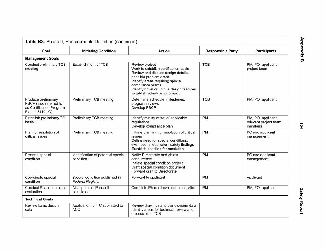
104Safety
Report
Tabl
ble Party Participants
ManaCondmeet
PM, PO, applicant, project team
ProduPSCPas CePlan
PM, PO, applicant
Estabbasis
PM, PO, applicant, relevant project team members
Plan critica
PO and applicant management
Procecondi
PO and applicant management
Coordcondi
Applicant
Condevalu
PM, PO, applicant
TechReviedata
Appendix B
e B3: Phase II, Requirements Definition (continued)
Goal Initiating Condition Action Responsi
gement Goalsuct preliminary TCB ing
Establishment of TCB Review projectWork to establish certification basisReview and discuss design details, possible problem areasIdentify areas requiring special compliance teamsIdentify novel or unique design featuresEstablish schedule for project
TCB
ce preliminary (also referred to rtification Program
in 8110.4C)
Preliminary TCB meeting Determine schedule, milestones, program reviewsDevelop PSCP
TCB
lish preliminary TC Preliminary TCB meeting Identify minimum set of applicable regulationsDevelop compliance plan
PM
for resolution of l issues
Preliminary TCB meeting Initiate planning for resolution of critical issuesDefine need for special conditions, exemptions, equivalent safety findingsEstablish deadline for resolution
PM
ss special tion
Identification of potential special condition
Notify Directorate and obtain concurrenceInitiate special condition projectDraft special condition documentForward draft to Directorate
PM
inate special tion
Special condition published in Federal Register
Forward to applicant PM
uct Phase II project ation
All aspects of Phase II completed
Complete Phase II evaluation checklist PM
nical Goalsw basic design Application for TC submitted to
ACOReview drawings and basic design dataIdentify areas for technical review and discussion in TCB

105Safety
Report
Tabl
onsible Party Participants
ManaFinalicertifi
Project team, resource specialists, flight-test pilot
Prepa nt, ISC Working groups
Procecondiequiv
PO, project engineers, technical specialists, flight-test pilot
Appendix B
e B3: Phase II, Requirements Definition (continued)
Goal Initiating Condition Action Resp
gement Goalsze preliminary cation basis
Preliminary TCB meeting Review set of applicable regulationsDetermine means of complianceIdentify need for safety assessments and risk analysesIdentify special conditions, exemptions, equivalent safety findingsDevelop issue papers
PO
re MRBR proposal Establishment of MRB Review MSG-3 requirementsDevelop initial minimum maintenance and inspection requirementsPrepare Policy and Procedures Handbook (PPH)Formulate analysis approach and methods for identifying failuresIdentify Maintenance Significant Items (MSI) and Structural Significant Items (SSI)Provide working groups with data for MSI/SSI analysisIdentify potential CRMSubmit MRBR proposal to MRB
Applica
ss special tions, exemptions, alent safety findings
Preliminary TCB meetingIssue paper
Identify new designs, technologies Determine need for—special conditionsexemptionsequivalent safety findingsTrack critical issuesDevelop issue papers
PM
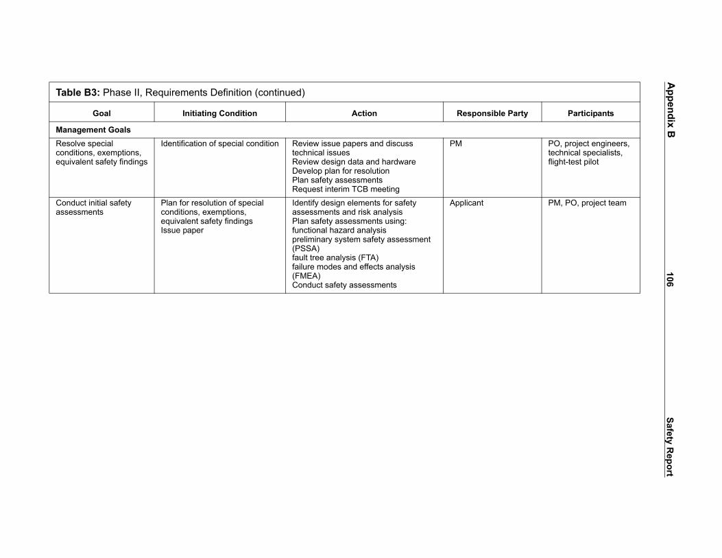
106Safety
Report
Tabl
sible Party Participants
ManaResocondiequiv
PO, project engineers, technical specialists, flight-test pilot
Condasses
PM, PO, project team
Appendix B
e B3: Phase II, Requirements Definition (continued)
Goal Initiating Condition Action Respon
gement Goalslve special tions, exemptions, alent safety findings
Identification of special condition Review issue papers and discuss technical issuesReview design data and hardwareDevelop plan for resolutionPlan safety assessmentsRequest interim TCB meeting
PM
uct initial safety sments
Plan for resolution of special conditions, exemptions, equivalent safety findingsIssue paper
Identify design elements for safety assessments and risk analysisPlan safety assessments using:functional hazard analysis preliminary system safety assessment (PSSA)fault tree analysis (FTA)failure modes and effects analysis (FMEA)Conduct safety assessments
Applicant

107Safety
Report
TableSourceFAA O
sible Party Participants
ManaCondmeet
PM, PO, applicant, project team (as required)
ProdureferrCertifPlan)
PM, PO, applicant
Compsched
PM, PO, applicant, project team
Estab PM, PO, applicant, relevant project team members
Compall iss
PO, applicant, project team
Compasses
PO, applicant
Procecondi
PO and applicant management
Appendix B
B4: Phase III, Compliance Planning The FAA and Industry Guide to Product Certification, 2nd Ed. Phase IIIrders 8110.4C, 8100.5, AC 25.1309-1A
Goal Initiating Condition Action Respon
gement Goalsuct interim TCB ings
As need arises Review issues, problemsDetermine plan for resolution
TCB
ce final PSCP (also ed to as ication Program
Initial safety assessmentsStage 1 issues resolutionComplete certification basis
Review PSCPIdentify any outstanding action itemsDevelop final PSCPSign PSCP
TCB
lete project ule
Final PSCP Establish milestones for—Safety assessmentsTest plan submissionType inspection authorization (TIA)Compliance and conformityFlight testsAEG evaluations and inspectionsCritical issues resolution
PM
lish TC basis Completion of compliance planIdentification of complete set of applicable regulations
Review TC basisApprove TC basisProduce compliance checklist
PM
lete initial draft of ue papers
Plan for resolution of critical issuesIssue paper
Develop plan for resolving issue papers PM
lete initial safety sments
Plan for resolution of critical issuesIssue paper
Review status of safety system assessmentsIdentify action items for completing initial assessments
PM
ss special tion
Identification of potential special conditionIssue paper
Notify Directorate and obtain concurrenceInitiate special condition projectDraft special condition documentForward draft to Directorate
PM

108Safety
Report
Tabl
sponsible Party Participants
ManaCoordcondi
Applicant
Obtaisafety
PO, applicant, relevant project team members
Proceexem
PM, applicant
Deterproce
PO, applicant, project team
Ident PM, applicant
Defindeleg
Applicant
Condevalu
PM, PO, applicant
TechReviedata
Appendix B
e B4: Phase III, Compliance Planning (continued)
Goal Initiating Condition Action Re
gement Goalsinate special
tionSpecial condition published in Federal Register
Forward to applicant PM
n equivalent level of finding
Proposed equivalent level of safety submitted by applicant
Review proposalObtain technical inputSubmit proposal to Directorate with recommendations for decision
PM
ss petition for ption
Submission of petition for exemption
Review petitionSubmit petition to applicable Directorate
PM
mine conformity dures
Draft PSCP Identify elements of design requiring tests and inspections for conformityEstablish procedures for conformity tests and inspections
PM
ify stakeholders Draft PSCP Develop list of stakeholders, including:SuppliersInstallers
PM
e oversight ation
Draft PSCP Identify oversight and documentation requirementsDetermine which elements of project to be delegatedIdentify designeesInclude delegations and oversight criteria in final PSCP
PM
uct Phase III project ation
All aspects of Phase III completed
Complete Phase III evaluation checklist PM
nical Goalsw basic design Application for TC submitted to
ACOReview drawings and basic design dataIdentify areas for technical review and discussion in TCB

109Safety
Report
Tabl
sible Party Participants
ManaFinalicertifi
Project team, resource specialists, flight-test pilot
Asseof saf
PO, relevant project team members
Deve am PM, PO, project engineers, technical specialists, flight-test pilot, inspectors
Proce PO, project team, project engineers, resource specialists, flight-test pilot, inspectors
Condasses
PM, PO, project team
Appendix B
e B4: Phase III, Compliance Planning (continued)
Goal Initiating Condition Action Respon
gement Goalsze preliminary cation basis
Preliminary TCB meeting Review set of applicable regulationsDetermine means of complianceIdentify need for safety assessments and risk analysesIdentify special conditions, exemptions, equivalent safety findingsDevelop issue papers
PO
ss equivalent level ety finding proposal
Proposed equivalent level of safety submitted by applicant
Review proposal and compensating factorsProvide input for recommendation
PM
lop issue paper As need arises Identify certification issue or problemConduct technical discussion with project teamDraft issue paperSubmit to TCB for resolution
Project te
ss issue paper Issue paper Review issue papers and discuss technical issuesDevelop plan for resolutionPlan safety assessments and risk analysesPresent plans and results to TCB
PM
uct safety sments
Plan for resolution of special conditions, exemptions, equivalent safety findingsIssue paper
Identify design elements for safety assessmentsPlan safety assessments using:functional hazard analysis (FHA)PSSAFTAFMEAConduct safety assessments and risk analyses
Applicant

110Safety
Report
TableSourceFAA O
ble Party Participants
ManaCondmeet
PM, PO, applicant, project team (as required)
PrepaTCB
PM, PO, applicant
Demo PM, PO, applicant
Appro Applicant, AEG, ISC, WGs
CondMeet
PM, PO, applicant
Procecondi
PO and applicant management
Coordcondi
Applicant
Obtaisafety
PO, applicant, relevant project team members
Appendix B
B5: Phase IV, Implementation: The FAA and Industry Guide to Product Certification, 2nd Ed. Phase IVrders 8110.4C, 8100.5A, AC 25.1309-1A
Goal Initiating Condition Action Responsi
gement Goalsuct interim TCB ings
As need arises Review issues, problemsDetermine plan for resolution
TCB
re for pre-flight meeting
Resolution of compliance and conformity issues
Identify outstanding conformity and compliance issues
TCB
nstrate compliance Submission of type design and substantiating data by applicant
Determine if all conformity and compliance issues have been resolvedDetermine if all appropriate engineering activities have been accomplished
TCB
ve MRB Report Submission of MRBR proposal by applicant
Review ISC and working group (WG) reportsReview and resolve any outstanding problems or issuesApprove MRBR
MRB
uct pre-flight TCB ing
Compliance demonstrated Review Aircraft Certification Service (AIR) Risk Assessment Process resultsIdentify any outstanding:Conformity inspection issuesEngineering compliance issuesIssue TIA
TCB
ss special tion
Identification of potential special conditionIssue paper
Notify Directorate and obtain concurrenceInitiate special condition projectDraft special condition documentForward draft to Directorate
PM
inate special tion
Special condition published in Federal Register
Forward to applicant PM
n equivalent level of finding
Proposed equivalent level of safety submitted by applicant
Review proposalObtain technical inputSubmit proposal to Directorate with recommendations for decision
PM

111Safety
Report
Tabl
sponsible Party Participants
ManaProceexem
PM, applicant
Condmeet
PM, PO, applicant
Condproje
PM, PO, applicant
TechEvaludesig
engineer PO, project team, AEG
Devecertifi
licant PM, PO
Revie engineer PO, project team
Deve ect team PM, PO, project engineers, technical specialists, flight-test pilot, inspectors
Appendix B
e B5: Phase IV, Implementation (continued)
Goal Initiating Condition Action Re
gement Goalsss petition for ption
Submission of petition for exemption
Review petitionSubmit petition to applicable Directorate
PM
uct final TCB ing
Completion of all tests Review status of all outstanding items and issuesFormalize decision to issue TCIssue TC when all items and issues resolved
TCB
uct Phase IV ct evaluation
All aspects of Phase IV completed
Complete Phase IV evaluation checklist PM
nical Goalsate and approve n data
Submission of type design and substantiating data by applicant
Review data, drawings, specifications, and reportsIdentify applicable airworthiness standardsIdentify any operational considerationsDetermine if compliance is completeUpdate and complete test planIdentify necessary tests and inspections
FAA
lop plan for cation testing
Submission of type design and substantiating data by applicant
Define test articlesDevelop test planSubmit test plan
App
w test plan Test plan submitted by applicant Review test planDetermine if test plan is complete for all necessary productsApprove test plan
FAA
lop issue paper As need arises Identify certification issue or problemConduct technical discussion with project teamDraft issue paperSubmit to TCB for resolution
Proj

112Safety
Report
Tabl
Responsible Party Participants
ManaProce PM PO, project team,
project engineers, resource specialists, flight-test pilot, inspectors
Asseof saf
PM PO, relevant project team members
Condinspe
FAA inspector PO, project team, AEG inspectors
CondAEG inspe
FAA inspector PO, AEG, project team
Appendix B
e B5: Phase IV, Implementation (continued)
Goal Initiating Condition Action
gement Goalsss issue paper Issue paper Review issue papers and discuss
technical issuesDevelop plan for resolutionPlan safety assessments and risk analysesPresent plans and results to TCB
ss equivalent level ety finding proposal
Proposed equivalent level of safety submitted by applicant
Review proposal and compensating factorsProvide input for recommendation
uct conformity ctions
Submission of type design and substantiating data by applicant
Identify products requiring inspectionsRequest and schedule inspectionsReview results of inspectionPrepare Conformity Inspection Report (CIR)
uct engineering and compliance ctions
Submission of type design and substantiating data by applicant
Identify products/installations/systems requiring inspection for compliance with regulationsReview and inspection maintenance proceduresDelegate to appropriate designated engineering representative (DER)Schedule inspectionsEnsure compliance and conformityReview results and issue notification of noncompliance where appropriateProduce Type Inspection Reports (TIRs)Prepare Conformity Inspection Record (CIR)Produce issue papers

113Safety
Report
Tabl
ible Party Participants
ManaPrepatest p
tor PM, PO, applicant, project team
Condairwo
tor FSB, AEG, PO, project team
Cond tor FOEB, PM, PO, AEG, flight-test pilot, project team
Cond
Appro PM, FOEB, AEG, flight-test pilot, applicant
Appendix B
e B5: Phase IV, Implementation (continued)
Goal Initiating Condition Action Respons
gement Goalsre flight and ground lan
Issuance of TIA Review compliance with regulationsPerform AIR risk management processDetermine—Test article configurationTest equipment configurationExpected resultsIdentify tests to be witnessedIdentify any nonconformities and reportPrepare test plan
AEG inspec
uct operational and rthiness evaluations
Issuance of TIA Review maintenance programsDevelop MRBReview flight manualsDevelop master minimum equipment listEstablish type rating requirementsDetermine crew complimentEstablish training requirementsProduce issue papersPrepare TIRsPrepare Conformity Inspection Record (CIR)
AEG inspec
uct ground tests Approval of test plan Conduct preliminary ground tests (Phase I)Obtain statement of conformityConduct official ground inspection of complete prototype (Phase II)Conduct coordinated ground-flight inspections (Phase III)Prepare TIRs
AEG inspec
uct flight tests Completion of ground tests and inspectionsFlight test report from applicant
Conduct flight tests in plan
ve flight manual Submission of type design and substantiating data by applicant
Review operational limitations, normal and emergency proceduresReview performance section of manual
PO

114Safety
Report
TableSource
`
sible Party Participants
ManaDevesumm
PM, PO, applicant
Prepa PM, PO, AEG
PrepaConti(ICA)
PM, PO, AEG
DeveMana
AEG
Condevalu
PM, PO, applicant
Appendix B
B6: Phase V, Post Certification: The FAA and Industry Guide to Product Certification, 2nd Ed. Phase V, FAA Orders 8110.4C, 8100.5A
Goal Initiating Condition Action Respon
gement Goalslop compliance ary report
Issuance of TC Summarize record of FAA examinationsDiscuss significant safety issuesDescribe how complied with applicable airworthiness, noise and emissions requirements
ACO
re TIRs Completion of all TIA inspections and tests
Prepare TIR, Part I, Ground InspectionPrepare TIR, Part II, Flight Test
ACO
re Instructions for nued Airworthiness
Completion of all TIA inspections and tests
Review ICA and airworthiness limitationsApprove ICAPublish ICA
ACO
lop Certificate gement Plan
Completion of all TIA inspections and tests
Establish Certificate Management TeamIncorporate airworthiness, maintenance, and operations requirements in planIncorporate provisions for Special Certification Reviews (SCR)
ACO
uct Phase V project ation
All aspects of Phase V completed
Complete Phase V evaluation checklist PM

115 Safety Report
Appendix C: Transport-Category Airplane-Related Accidents
Table C1. Transport-Category Airplane-Related Accidents, 1962–2000
Failed Airplane ElementNumber of Airplane-Related Accidents Type of System or Component Failure
Airplane Structure 14 Wing failure/separationCargo door failureEngine pylon separationBulkhead failureJackscrew assembly failure
Engine/Propulsion System 9 Thrust reverser deployedBeta in flightPropeller moved below idlePropeller separation in flight
Engine Containment 6 Fan rotor failureCombustor failureFront hub failure
Flight/Ground Control System 10 Ground spoiler deploymentUncommanded rudder movementYaw damper failureVertical stabilizer separation
Fuel Tank System 6 Fuel tank explosion, loss of wingFuel tank explosion, in-flight breakupFuel tank fire
Fire Suppression or Detection 2 Cargo hold fireCockpit electrical fire
Structural Icing 8 Wing icingFixed leading edgeUncommanded aileron movement

116Safety
Report
use/Factort wing resulting from forces propeller whirl mode
g in flight due to flutter induced by d nacelles. Contributing factors of the structure
cargo door and sudden orrect engagement of the door
re takeoff
latching mechanism for aft cargo r flight
ilizer rear spar top chord failed due to long-term fatigue damage
gine and pylon assembly during aintenance
the separation of the fuselage to detect presence of disbonding
ward cargo door in flight and the on attributed to faulty door control lectrical actuation of the door
engine during landing roll due to nal-brace aft fuse-pin on engine
engines due to pylon failures
engines due to fatigue in pylon ign
ilure
ght decompression due to fatigue
ing from the in-flight failure of the orizontal stabilizer trim system
Appendix C
Airplane Structure
Air CarrierAirplane
Make/Model Location Date CaBraniff Airlines L-188 Buffalo, NY 9/29/59 structural failure of the lef
generated by undamped
Northwest Airlines L-188 Cannelton, IN 3/17/60 separation of the right winoscillations of the outboarwere a reduced stiffness
Turkish Airlines DC-10 Paris, France 3/03/74 ejection in flight of the aftdecompression due to inclatching mechanism befo
American Airlines DC-10 Windsor, Canada 6/12/72 improper engagement of door during preparation fo
DAN AIR B-707 Lusaka, Zambia 5/14/77 right hand horizontal stabprior to the accident flight
American Airlines DC-10 Chicago, IL 5/25/79 separation of the No.1 entakeoff due to improper m
Aloha Airlines B-737 Maui, HI 4/28/88 failure of the lap joint andupper lobe due to a failureand fatigue damage
United Airlines B-747 Honolulu, HI 6/15/90 sudden opening of the forsubsequent decompressisystem which permitted elatches
Air India B-747 Delhi, India 5/07/70 partial separation of No. 1improperly installed diago
China Air B-747 Wanli, Taiwan 12/29/91 Separation of No. 3 and 4
El Al B-747 Amsterdam, Holland 10/04/92 Separation of No. 3 and 4and inadequate pylon des
Japan Airlines B-747 Mt. Ogura, Japan 8/21/95 rear pressure bulkhead fa
Delta Airlines L-1011 Pacific Ocean 8/23/95 bulkhead failure and in-flicracking
Alaska Airlines MD-83 Point Hueneme, Ca 1/31/00 loss of pitch control resultacme nut threads in the hjackscrew assembly

117Safety
Report
use/Factorin flight
on take-off
on take-off
quate lockout
ght idle in flight
ght idle in flight
ht
se/Factorrs in landing flare due to t mechanism
ment due to jam of main rudder
heck, M. Moore
ment due to jam of main rudder
ment due to jam of main rudder
ment
ement on depart
from the in-flight failure of the izontal stabilizer trim system
er due to high sideslip angle uts
Appendix C
Engine/Propulsion Systems
Air CarrierAirplane
Make/Model Location Date CaLauda B-767 Thailand 5/26/91 thrust reverser deployed
TAM Fokker 100 Sao Paulo, Brazil 10/31/96 thrust reverser deployed
TWA B-717 Milwaukee, WI 2/19/01 thrust reverser deployed
Fisher Brothers Aviation Casa-212 Romulus, MI 3/04/87 beta in flight due to inade
Executive Air Casa-212 Mayaguez, PR 5/08/87 beta in flight
ASA Embraer-120 Brunswick, GA 4/05/91 propeller moved below fli
Executive Air Casa-212 Mayaguez, PR 6/07/92 beta in flight
American Eagle Saab-340 New Roads, LA 2/01/94 propeller moved below fli
ASA Embraer-120 Carrollton, GA 8/21/95 propeller separation in flig
Flight/Ground Control Systems
Air CarrierAirplane
Make/Model Location Date CauAir Canada DC-8 Toronto, Canada 7/05/70 deployment of ground spoile
inadequate design of lockou
United Airlines B-737 Colorado Springs, CO 3/03/91 uncommanded rudder movePCU servo valve
United Airlines B-737 Chicago, Il 7/16/92 rudder anomaly at ground c
USAir B-737 Aliquippa, PA 9/08/94 uncommanded rudder movePCU servo valve
Eastwind Airlines B-737 Richmond, VA 6/09/96 uncommanded rudder movePCU servo valve
Metrojet B-737 Salisbury, MD 2/23/99 uncommanded rudder move
various B-737 yaw damper events
British Airways B-747 London, England 10/07/93 uncommanded elevator mov
Alaska Airlines MD-83 Point Hueneme, CA 1/31/00 loss of pitch control resultingacme nut threads in the horjackscrew assembly
American Airlines A300-605R Belle Harbor, NY 11/12/01 separation of vertical stabilizcaused by pilot’s rudder inp

118Safety
Report
Fuel
Cause/FactorPan A n of the left outer wing and loss of
g-induced ignition of the fuel/air serve fuel tank
Irania due to lightning strike in vicinity of No.
Avian e to explosive device igniting the fuel-r or No. 2 tank
Philip xplosion on ground due to ignition of
TWA r wing fuel tank, resulting from ignition e tank most probably due to a short nk
Thai t
Fire S
Cause/FactorValuJ ignition of oxygen generators
Swiss proper installation of in-flight
Appendix C
Tank System
Air CarrierAirplane
Make/Model Location Datemerican Airlines B-707 Elkton, MD 12/08/63 explosive disintegratio
control due to lightninmixture in the No. 1 re
n Air Force B-747 Madrid, Spain 5/09/76 separation of left wing1 fuel tank
ca B-727 Bogota, Colombia 11/27/89 separation of wings duair vapors in the cente
pines Airlines B-737 Manila, Philippines 5/11/90 center wing fuel tank efuel tank vapors
800 B-747 East Moriches, NY 6/17/96 explosion of the centeof fuel/air mixture in thcircuit outside of the ta
Airways B-737 Bangkok, Thailand 3/02/01 CFT, pump, wire shor
uppression/Detection
Air CarrierAirplane
Make/Model Location Dateet DC-9 Everglades, FL 5/11/96 cargo hold fire due to
Air MD-11 Nova Scotia, Canada 9/02/98 electrical fire due to imentertainment system

119Safety
Report
Engin
Cause/FactorNatio
Britis
Midw
Unite
ValuJ ture
Delta
Struc
Cause/FactorAir Fl
Airbo
Conti after deicing resulting in a fixed
Mid P
Ryan eicing resulting in a fixed leading
USAi eicing resulting in a fixed leading
Amer movement
COM resulting in a fixed leading edge
Appendix C
e Containment
Air CarrierAirplane
Make/Model Location Datenal Airlines DC-10 Albuquerque, NM 11/03/73 Fan rotor failure
h Airtours B-737 Manchester, Englnd 8/22/85 Combuster can failure
est Express DC-9 Milwaukee, WI 9/06/85 HPC spacer failure
d Airlines DC-10 Sioux City, IA 10/08/92 Fan rotor failure
et DC-9 Atlanta, GA 6/08/95 7th stage HPC disk rup
MD-88 Pensacola, FL 3/31/98 front hub failure
tural Icing
Air CarrierAirplane
Make/Model Location Dateorida B-737 Washington, DC 1/13/82 icing- wing/engines
rne Express DC-9 Philadelphia, PA 2/05/85 wing icing
nental Airlines DC-9 Stapleton, CO 11/15/87 during take-off, 27 minleading edge
acific Airlines YS-11A West Lafayette, IN 3/15/89 icing on approach
International DC-9-15 Cleveland, OH 2/17/91 during take-off, after dedge
r F-28 Flushing, NY 3/22/92 during take-off, after dedge
ican Eagle ATR-72 Roselawn, IN 10/31/94 uncommanded aileron
AIR EMB-120 Monroe, MI 1/09/97 wing ice while holding

120 Safety Report
Appendix D: Status and Disposition of NTSB Safety Recommendations
Safety Recommendation Letter Status
The full text of the NTSB Safety Recommendations for each of the accidentinvestigations discussed in the report is presented in this appendix. Included are currentstatus of the recommendation and the date of the latest correspondence showing the sourceand the recipient, as of April 21, 2005. More details about each of the recommendationscan be found on the National Transportation Safety Board website at<www.ntsb.gov/Recs/index.htm.>
United Airlines Flight 585
A-92-120Require operators, by airworthiness directive, to incorporate designchanges for the B-737 main rudder power control unit servo valve whenthese changes are made available by Boeing. These changes shouldpreclude the possibility of rudder reversals attributed to the overtravel ofthe secondary slide.
Status: Closed—Acceptable ActionMost Recent Correspondence: NTSB response to FAA on 8/11/1994
A-92-121Conduct a design review of servo valves manufactured by Parker Hannifinhaving a design similar to the B-737 rudder power control unit servo valvethat control essential flight control hydraulic power control units ontransport-category airplanes certified by the Federal AviationAdministration to determine that the design is not susceptible to inducingflight control malfunctions due to overtravel of the servo slides.
Status: Closed—Acceptable ActionMost Recent Correspondence: NTSB response to FAA on 6/10/1993
USAir Flight 427 Accident Investigation
A-99-21Convene an engineering test and evaluation board to conduct a failure analysis toidentify potential failure modes, a component and subsystem test to isolateparticular failure modes found during the failure analysis, and a full-scaleintegrated systems test of the Boeing 737 rudder actuation and control system toidentify potential latent failures and validate operation of the system without

121 Safety ReportAppendix D
regard to minimum certification standards and requirements in 14 Code of FederalRegulations Part 25. Participants in the engineering test and evaluation boardshould include the Federal Aviation Administration (FAA); NationalTransportation Safety Board technical advisors; the Boeing Company; otherappropriate manufacturers; and experts from other government agencies, theaviation industry, and academia. A test plan should be prepared that includesinstallation of original and redesigned Boeing 737 main rudder power control unitsand related equipment and exercises all potential factors that could initiateanomalous behavior (such as thermal effects, fluid contamination, maintenanceerrors, mechanical failure, system compliance, and structural flexure). Theengineering board’s work should be completed by March 31, 2000, and publishedby the FAA.
Status: Closed—Acceptable ActionMost Recent Correspondence: NTSB response to FAA on 4/25/2001
A-99-23Amend 14 Code of Federal Regulations Section 25.671(c)(3) to requirethat transport-category airplanes be shown to be capable of continued safeflight and landing after jamming of a flight control at any deflectionpossible, up to and including its full deflection, unless such a jam is shownto be extremely improbable.
Status: Open—Unacceptable Response (referral to ARAC does not meanrecommended action has been taken)Most Recent Correspondence: NTSB response to FAA on 4/25/2001
TWA Flight 800
A-96-174Require the development of and implementation of design or operationalchanges that will preclude the operation of transport-category airplaneswith explosive fuel-air mixtures in the fuel tank: (a) significantconsideration should be given to the development of airplane designmodifications, such as nitrogen-inerting systems and the addition ofinsulation between heat-generating equipment and fuel tanks. Appropriatemodifications should apply to newly certificated airplanes and, wherefeasible, to existing airplanes.
Status: Open—Acceptable ResponseMost Recent Correspondence: FAA response to NTSB on 2/1/2005

122 Safety ReportAppendix D
A-96-175Require the development of and implementation of design or operationalchanges that will preclude the operation of transport-category airplaneswith explosive fuel-air mixtures in the fuel tanks: (b) pendingimplementation of design modifications, require modifications inoperational procedures to reduce the potential for explosive fuel-airmixtures in the fuel tanks of transport-category aircraft. In the B-747,consideration should be given to refueling the center wing fuel tank (CTW)before flight whenever possible from cooler ground fuel tanks, propermonitoring and management of the CWT fuel temperature, andmaintaining an appropriate minimum fuel quantity in the CWT.
Status: Closed—Unacceptable ActionMost Recent Correspondence: NTSB response to FAA on 11/15/2005
Alaska Airlines Flight 261
A-02-41Review all existing maintenance intervals for tasks that could affect criticalaircraft components and identify those that have been extended withoutadequate engineering justification in the form of technical data andanalysis demonstrating that the extended interval will not present anyincreased risk and require modifications of those intervals to ensure thatthey (1) take into account assumptions made by the original designers, (2)are supported by adequate technical data and analysis, and (3) include anappropriate safety margin that takes into account the possibility of missedor inadequate accomplishment of the maintenance task. In conducting thisreview, the Federal Aviation Administration should also consider originalintervals recommended or established for new aircraft models that arederivatives of earlier models and, if the aircraft component and the task aresubstantially the same and the recommended interval for the new model isgreater than that recommended for the earlier model, treat such originalintervals for the derivative model as "extended" intervals.
Status: Open—Acceptable Alternate ResponseMost Recent Correspondence: NTSB response to FAA on 1/13/2005
A-02-42Conduct a systematic industrywide evaluation and issue a report on theprocess by which manufacturers recommend and airlines establish andrevise maintenance task intervals and make changes to the process toensure that, in the future, intervals for each task (1) take into accountassumptions made by the original designers, (2) are supported by adequatetechnical data and analysis, and (3) include an appropriate safety marginthat takes into account the possibility of missed or inadequateaccomplishment of the maintenance task.
123 Safety ReportAppendix D
Status: Open—Acceptable ResponseMost Recent Correspondence: NTSB response to FAA on 1/13/2005
A-02-43Require operators to supply the Federal Aviation Administration (FAA),before the implementation of any changes in maintenance task intervalsthat could affect critical aircraft components, technical data and analysisfor each task demonstrating that none of the proposed changes will presentany potential hazards, and obtain written approval of the proposed changesfrom the principal maintenance inspector and written concurrence from theappropriate FAA aircraft certification office.
Status: Open—Acceptable ResponseMost Recent Correspondence: NTSB response to FAA on 1/13/2005
A-02-45Require operators to permanently (1) track end play measures according toairplane registration number and jackscrew assembly serial number, (2)calculate and record average wear rates for each airplane based on end playmeasurements and flight times, and (3) develop and implement a programto analyze these data to identify and determine the cause of excessive orunexpected wear rates, trends, or anomalies. The Federal AviationAdministration (FAA) should also require operators to report thisinformation to the FAA for use in determining and evaluating anappropriate end play check interval.
Status: Open—Acceptable Alternate ResponseMost Recent Correspondence: NTSB response to FAA on 1/13/2005
A-02-49Conduct a systematic engineering review to (1) identify means to eliminatethe catastrophic effects of total acme nut thread failure in the horizontalstabilizer trim system jackscrew assembly in Douglas DC-9 (DC-9),McDonnell Douglas MD-80/90 (MD-80/90), and Boeing 717 (717) seriesairplanes and require, if practicable, that such fail-safe mechanisms beincorporated in the design of all existing and future DC-9, MD-80/90, and717 series airplanes and their derivatives; (2) evaluate the horizontalstabilizer trim systems of all other transport-category airplanes to identifyany designs that have a catastrophic single-point failure mode and, for anysuch system; (3) identify means to eliminate the catastrophic effects of thatsingle-point failure mode and, if practicable, require that such fail-safemechanisms be incorporated in the design of all existing and futureairplanes that are equipped with such horizontal stabilizer trim systems.
Status: Open—Acceptable ResponseMost Recent Correspondence: NTSB response to FAA on 1/13/2005

124 Safety ReportAppendix D
A-02-50Modify the certification regulations, policies, or procedures to ensure thatnew horizontal stabilizer trim control system designs are not certified ifthey have a single-point catastrophic failure mode, regardless of whetherany element of that system is considered structure rather than system or isotherwise considered exempt from certification standards for systems.
Status: Open—Acceptable ResponseMost Recent Correspondence: NTSB response to FAA on 1/13/2005
A-02-51Review and revise aircraft certification regulations and associated guidanceapplicable to the certification of transport-category airplanes to ensure thatwear-related failures are fully considered and addressed so that, to themaximum extent possible, they will not be catastrophic.
Status: Open—Acceptable ResponseMost Recent Correspondence: NTSB response to FAA on 1/13/2005
American Airlines Flight 587
A-04-56Modify 14 Code of Federal Regulations Part 25 to include a certificationstandard that will ensure safe handling qualities in the yaw axis throughoutthe flight envelope, including limits for rudder pedal sensitivity.
Status: Open—Acceptable ResponseMost Recent Correspondence: NTSB response to FAA on 8/3/2005
A-04-57After the yaw axis certification standard recommended in SafetyRecommendation A-04-56 has been established, review the designs ofexisting airplanes to determine if they meet the standard. For existingairplanes designs that do not meet the standard, the FAA should determineif the airplanes would be adequately protected from the adverse effects of apotential aircraft-pilot coupling (APC) after rudder inputs at all airspeeds.If adequate protection does not exist, the FAA should requiremodifications, as necessary, to provide the airplanes with increasedprotection from the adverse effects of a potential APC after rudder inputs athigh airspeeds.
Status: Open—Acceptable ResponseMost Recent Correspondence: NTSB response to FAA on 8/3/2005

125 Safety ReportAppendix D
A-04-58Review the options for modifying the Airbus A300-600 and the AirbusA310 to provide increased protection from potentially hazardous rudderpedal inputs at high airspeeds and, on the basis of this review, requiremodifications to the A300-600 and A310 to provide increased protectionfrom potentially hazardous rudder pedal inputs at high airspeeds.
Status: Open—Acceptable ResponseMost Recent Correspondence: NTSB response to FAA on 8/3/2005
A-04-60Amend all relevant regulatory and advisory materials to clarify thatoperating at or below maneuvering speed does not provide structuralprotection against multiple full control inputs in one axis or full controlinputs in more than one axis at the same time.
Status: Open—Acceptable ResponseMost Recent Correspondence: NTSB response to FAA on 8/3/2005
A-04-63Review the options for modifying the Airbus A300-600 and the AirbusA310 to provide increased protection from potentially hazardous rudderpedal inputs at high airspeeds and, on the basis of this review, requiremodifications to the A300-600 and A310 to provide increased protectionfrom potentially hazardous rudder pedal inputs at high airspeeds.
Status: Open—Acceptable ResponseMost Recent Correspondence: NTSB response to EASA on 8/3/2005