Systematic framework for the efficient integration of wind ... · Weisbrich and Pucher, 1996). ......
14
HOSTED BY www.elsevier.com/locate/foar Available online at www.sciencedirect.com RESEARCH ARTICLE Systematic framework for the efficient integration of wind technologies into buildings Ashraf A. ELMokadem, Naglaa A. Megahed, Dina S. Noaman n Architecture and Urban Planning Department, Faculty of Engineering, Port-Said University, Port Said, Egypt Received 27 August 2015; received in revised form 26 December 2015; accepted 31 December 2015 KEYWORDS Building integrated wind technology; Integration method; Systematic framework Abstract The renewed interest that is being paid by architects, project developers and local govern- ments to integrate wind turbines with buildings is mainly required a framework to unify much data, criteria and variables to ease the design process to many architects. Therefore, this paper introduces and elaborates the systematic framework towards the efficient integration of wind technologies into new building. Moreover, it evaluates the framework effectiveness by comparing the current status of wind technologies integration into a building with the suggested status if the framework is followed. & 2016 Higher Education Press Limited Company. Production and hosting by Elsevier B.V. This is an open access article under the CC BY-NC-ND license (http://creativecommons.org/licenses/by-nc-nd/4.0/). 1. Introduction The increasing threats of climate change, along with diminishing fossil fuel energy sources, and uncertainty over the security of energy supplies, underscore the increasing value of renewable energy technologies. According to the Intergovernmental Panel on Climate Change (IPCC), buildings are responsible for one-third of global energy-related CO 2 because of their dependency on fossil fuels (Urge-Vorsatz, 2007). As a result, it is imperative that; architects and engineers should find http://dx.doi.org/10.1016/j.foar.2015.12.004 2095-2635/& 2016 Higher Education Press Limited Company. Production and hosting by Elsevier B.V. This is an open access article under the CC BY-NC-ND license (http://creativecommons.org/licenses/by-nc-nd/4.0/). Abbreviations: IPCC, Intergovernmental Panel on Climate Change; WTs, Wind Technologies; BIWT, Building Integrated Wind Technology; HAWTs, Horizontal Axis WTs; VAWTs, Vertical Axis WTs; WARP, Wind Amplified Rotor Platform; IBL, Internal Boundary Layer. n Corresponding author. Tel.: + 20 1221535573. E-mail address: [email protected] (D.S. Noaman). Peer review under responsibility of Southeast University. Frontiers of Architectural Research (2016) 5,1–14
Transcript of Systematic framework for the efficient integration of wind ... · Weisbrich and Pucher, 1996). ......

Frontiers of Architectural Research (2016) 5, 1–14
H O S T E D B Y Available online at www.sciencedirect.com
http://dx.doi.2095-2635/& 2CC BY-NC-ND l
AbbreviationChange; WTs,Technology; HWARP, Wind Am
nCorrespondE-mail addPeer review
www.elsevier.com/locate/foar
RESEARCH ARTICLE
Systematic framework for the efficientintegration of wind technologiesinto buildings
Ashraf A. ELMokadem, Naglaa A. Megahed, Dina S. Noamann
Architecture and Urban Planning Department, Faculty of Engineering, Port-Said University, Port Said,Egypt
Received 27 August 2015; received in revised form 26 December 2015; accepted 31 December 2015
KEYWORDSBuilding integratedwind technology;Integration method;Systematic framework
org/10.1016/j.foar.2015016 Higher Education Pricense (http://creativec
s: IPCC, IntergovernWind Technologies; BIWAWTs, Horizontal Axis Wplified Rotor Platform;
ing author. Tel.: +20 12ress: dinasamy87@gmailunder responsibility of
AbstractThe renewed interest that is being paid by architects, project developers and local govern-ments to integrate wind turbines with buildings is mainly required a framework to unify muchdata, criteria and variables to ease the design process to many architects. Therefore, this paperintroduces and elaborates the systematic framework towards the efficient integration of windtechnologies into new building. Moreover, it evaluates the framework effectiveness bycomparing the current status of wind technologies integration into a building with thesuggested status if the framework is followed.& 2016 Higher Education Press Limited Company. Production and hosting by Elsevier B.V. This isan open access article under the CC BY-NC-ND license(http://creativecommons.org/licenses/by-nc-nd/4.0/).
.12.004ess Limited Company. Productionommons.org/licenses/by-nc-nd/4
mental Panel on ClimateT, Building Integrated WindTs; VAWTs, Vertical Axis WTs;IBL, Internal Boundary Layer.21535573..com (D.S. Noaman).Southeast University.
1. Introduction
The increasing threats of climate change, along withdiminishing fossil fuel energy sources, and uncertaintyover the security of energy supplies, underscore theincreasing value of renewable energy technologies.According to the Intergovernmental Panel on ClimateChange (IPCC), buildings are responsible for one-third ofglobal energy-related CO2 because of their dependencyon fossil fuels (Urge-Vorsatz, 2007). As a result, it isimperative that; architects and engineers should find
and hosting by Elsevier B.V. This is an open access article under the.0/).
A.A. ELMokadem et al.2
building's design ways to decrease its amount of fossilfuels consumption. One of the ways is the integration ofwind technologies (WTs) into the primary building designto produce energy where it is consumed.
Building Integrated Wind Technology (BIWT) is becomingincreasingly common as a green building icon to achieveenergy self-sufficient building. However, the integration ofWTs into buildings has not reached its goal yet. The reason isthe absence of a framework that helps the architects toachieve the efficient integration. Therefore, this paper aimsto introduce this efficient integration framework, whichincludes four stages: (1) determining site suitability;(2) determining suitable integration methods; (3) determin-ing suitable WTs; and (4) comparing energy production withconsumption. Then, this systematic framework is applied onStrata SE1 building in London, UK and the results are used tocompare the building's current status with other integrationmethods when applied to the case study in its conceptualdesign phase. The results of these four stages and theiranalyses were finally combined and synthesized in the casestudy building to evaluate the usability and effectiveness ofthe suggested systematic framework.
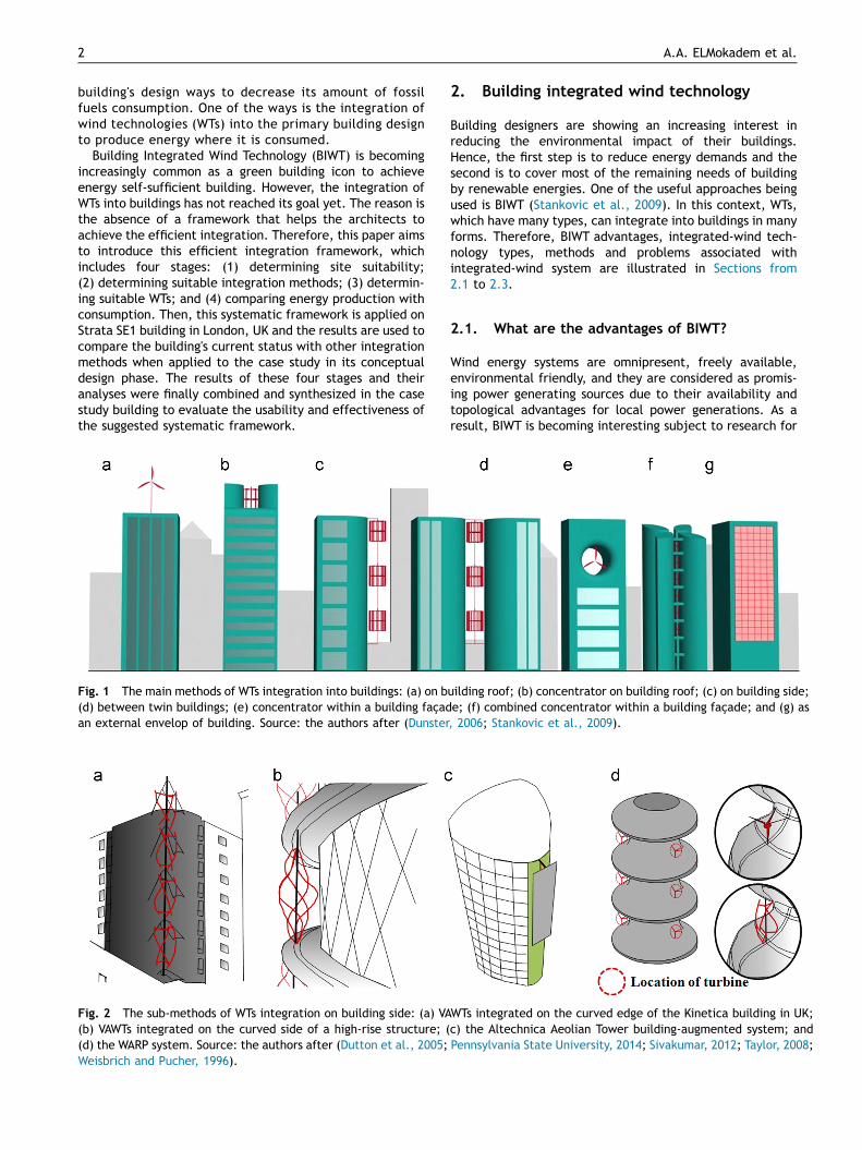
Fig. 2 The sub-methods of WTs integration on building side: (a) VA(b) VAWTs integrated on the curved side of a high-rise structure; ((d) the WARP system. Source: the authors after (Dutton et al., 2005;Weisbrich and Pucher, 1996).
Fig. 1 The main methods of WTs integration into buildings: (a) on b(d) between twin buildings; (e) concentrator within a building façadan external envelop of building. Source: the authors after (Dunster
2. Building integrated wind technology
Building designers are showing an increasing interest inreducing the environmental impact of their buildings.Hence, the first step is to reduce energy demands and thesecond is to cover most of the remaining needs of buildingby renewable energies. One of the useful approaches beingused is BIWT (Stankovic et al., 2009). In this context, WTs,which have many types, can integrate into buildings in manyforms. Therefore, BIWT advantages, integrated-wind tech-nology types, methods and problems associated withintegrated-wind system are illustrated in Sections from2.1 to 2.3.
2.1. What are the advantages of BIWT?
Wind energy systems are omnipresent, freely available,environmental friendly, and they are considered as promis-ing power generating sources due to their availability andtopological advantages for local power generations. As aresult, BIWT is becoming interesting subject to research for
WTs integrated on the curved edge of the Kinetica building in UK;c) the Altechnica Aeolian Tower building-augmented system; andPennsylvania State University, 2014; Sivakumar, 2012; Taylor, 2008;
uilding roof; (b) concentrator on building roof; (c) on building side;e; (f) combined concentrator within a building façade; and (g) as, 2006; Stankovic et al., 2009).

3Systematic framework for the efficient integration of wind technologies into buildings
most of architects around the world to learn, analysis anddesign with. BIWT is a building that is designed and shapedwith WT in mind. Therefore, a systematic framework isneeded to achieve efficient BIWT. Furthermore, the trendtowards BIWT is increasing because of BIWT advantageswhich are the following (Abohela et al., 2011; Beller, 2009;Cace et al., 2007; Stankovic et al., 2009): (a) support theWTs, (b) harness wind to be driven towards the WTs,(c) capture higher wind speeds because of the height,(d) reduce energy transmission losses, (e) reduce fossil fuelresources consumption, and finally, (f) increase CO2 savingsthat make a visible “green” image.
2.2. Integrated-wind technology: types andmethods
Generally, WTs, which harness the energy from the wind bythe conversion of kinetic energy into electrical one(American Wind Energy Association, 2003), can be dividedinto three main types: two types based on the axis in whichthe WT rotates (Horizontal Axis WTs (HAWTs) and VerticalAxis WTs (VAWTs)), in addition to the third type that includesother WTs such as Vibration and Millimeter Technologies.Moreover, each WT type has three sizes: pico (swept areafewer than 4.9 m2), small (swept area ranged from 4.9 tofewer than 300 m2) and medium (swept area equals or morethan 300 m2).
The main methods of WTs integration into buildings varyfrom integration on roof to integration as an externalenvelope (Fig. 1). In addition, each main integrationmethod has sub-methods such as integration on buildingside, which will be suggested for the case study building. Inthis context, integration on building side includes four sub-methods (Fig. 2): edge or corner, curved side, AeolianCorner and Wind Amplified Rotor Platform (WARP) system.
2.3. Problems associated with integrated-windsystem
The efficient integration of WTs into buildings should over-come the following fundamental considerations. First:treating vibration from WTs by installing vibration dampen-ing at the base and head of the WT (Breshears and Briscoe,2009). In addition, acoustic treatment should be done byisolating WTs from occupants with technical or servicespaces, in addition to separating between the WT andadjacent spaces. Second: designing the external envelopeof building to accelerate and not disturb the wind flowtowards the WT (Stankovic et al., 2009). Third: consideringsafety requirements in supporting the WTs (Beller, 2009;Syngellakis et al., 2007). Furthermore, maintenancerequirements should be considered by a straightforwardand a safe access to WTs components (Dutton et al., 2005).Moreover, a space within the building for WT system and apassage for cables between WT and main switchboard arerequired (Cace et al., 2007; Sharpe, 2010). Finally energyyield enlargement by the integration of multiple WTs on thesame building is favorable (Cace et al., 2007). In a technicalpoint of view, designing the Wind Turbine is such a complexengineering product, which requires integration of differentdisciplinary such as mechanical, electrical, structural as
well as architectural point of view. In other words, adequateaid efforts are needed to consider the expectation of eachindividual aspect of design, which required multidisciplinarystudy of many other specialist studies. However, the pre-sented paper presents only the architectural point of viewthat may encourage other specialists to add to the scientificknowledge.
3. The Science behind the systematicframework
Based upon our empirical work and conceptual analysis aswell as related research (for example Dutton et al., 2005;Lysen, 1983; Masters, 2004; Mertens, 2006; Stankovic et al.,2009; Tong, 2010), we define four stages (Fig. 3) that needto be followed when designing BIWT. These four stages forma comprehensive systematic framework, which not onlyserves to unify and define many charts, matrices, equationsand other scientific data to architects, but also serves as aplatform for the efficient integration of WTs into buildings.In this context, the four stages are illustrated in thefollowing points.
3.1. Stage 1. Determining site suitability forexploiting wind technologies
According to the suggested systematic framework, our firststage is the determination of site suitability to exploit WTs.This stage is affected mainly by regulations and surroundingobstacles' height, in addition to annual average wind speed.
3.1.1. Regulations and surrounding obstacles' heightBoth constructions permitted height and minimum suitableheight for WTs in a site should be determined and comparedas they effect on site suitability for WTs. Firstly, theconstruction permitted height can be determined fromheight regulations. Secondly, the minimum suitable heightfor all WTs types (except HAWTs) can be determined fromsurrounding obstacles' height, because the wake regions,which are created by the surrounding obstacles, should beavoided (Mcguire, 2003; Syngellakis and Traylor, 2007), asshown in Fig. 4. In that sense, if constructions permittedheight in the site equals or lower than the minimum suitableheight for WTs, the site will not be suitable to exploit WTs.
3.1.2. Annual average wind speedIt has long been recognized that the annual average windspeed of the site at the minimum suitable height for WTsshould be at least 4 m/s (Renewable UK, 2010). Therefore,firstly, the height (z) of 4 m/s annual average wind speed (V(z)) should be estimated by the logarithmic law if theavailable wind speed (V (zref)) is from the building site asfollowing (Lysen, 1983; Masters, 2004; Tong, 2010):
VðzÞ ¼ Vðzref Þ �lnðz�dÞ=z0
lnðzref�dÞ=z0m=s� � ð1Þ
where V (zref) is the available wind speed of the site (m/s)at reference height zref that is in the Internal BoundaryLayer (IBL) and above the height d, d is the displacementheight and defined as 0.75 of the average height of

Fig. 3 Systematic framework for the efficient integration of WTs into buildings.
Fig. 4 Building height requirements for exploiting WTs. Source: the authors after (Mcguire, 2003; Mertens, 2006; Syngellakis andTraylor, 2007).
A.A. ELMokadem et al.4
surrounding obstacles (m), z0 is the surface roughnesslength of the site (m) and can be calculated by (Masters,2004):
z0 ¼ 0:5� Ah �0H m=s
� � ð2Þwhere Ah is a percentage of the total area occupied byobstacles of average height Ή.
It is important to note that, if the available wind speed(VA (zA)) is from a near site, the height (z) is determined as(Masters, 2004):
VðzÞ ¼ VAðzAÞln ðz�dÞ
z0
ln ðδI �dÞz0
�ln δI
z0A
ln zAz0A
m=s� � ð3Þ
where VA (zA) is the available wind speed (m/s) at a heightzA, z0A is the surface roughness length of the site (m) wherethe VA (zA) is measured and can be calculated by Eq. (2), δIis the IBL height at a distance x from the site to the edge ofthe IBL (m) and can be calculated as follows (Lysen, 1983;Masters, 2004):
δI ¼ 0:28z0xz0
� �0:8mð Þ ð4Þ
Then, if constructions permitted height in the site equalsor lower than the determined height (z), the site will not besuitable to exploit WTs.
3.2. Stage 2. Determining suitable integrationmethods
The second stage identifies the suitable integration methodsor that are sorted by priority. In this regard, the selection isaffected by both site and integration method variables.
3.2.1. Site variablesSite variables that effect on the selection of suitableintegration methods are classified in the following divisions:

5Systematic framework for the efficient integration of wind technologies into buildings
� Available height for integration methods: Integrationon roof and in a concentrator on roof methods can only beused above building height, i.e. in the distance betweenbuilding height and construction permitted height. Inaddition, other methods can only be used under buildingheight, i.e. in the distance between the minimumsuitable height for WTs and building height. Furthermore,each integration method has height conditions. There-fore, by comparing building height with minimum suita-ble height for WTs and constructions permitted height,some integration methods cannot be used.
� Wind directions type: It can be uniform or weaklyunidirectional or strongly unidirectional or bi-directional.Therefore, each integration method has suitable and non-suitable wind directions' types. Hence, for any exact site,there are some non-suitable integration methods thatshould be excluded. For instance, if the site has uniformwind direction type, as in the case study building's site,some integration methods should be excluded such as theintegration between twin buildings and in concentratorwithin a building façade, in addition to all sub-methods ofthe integration on building side except the WARP system.
3.2.2. Integration methods variablesIntegration methods' variables that effect on the selectionand arrange the priorities of suitable integration methodsare grouped in the following categories:
� Dimensions and shape conditions: Any building hasdesigning conditions such as the inability to separate intotwo towers, the attachment to another building, theinability to shape near a circular plan …etc.., which leadto the exclusion of unsuitable methods.
� Ability to accelerate wind: It is compared to a freestanding WT at the same location. Further, it is varied fordifferent integration methods. Therefore, the priority ofintegration methods' selection or order should belong tointegration methods with the highest acceleration value.For example, the WARP system has acceleration valuearound 1.80 V (Dutton et al., 2005; Weisbrich and Pucher,1996), which is higher than the value of the integration ina combined concentrator within a building façade thatvary according to the sub-method from 0.78 V to 1.44 V(Hughes and Chaudhry, 2011; Mertens, 2006). As a result,the priority of selection or order between the twomethods belongs to the WARP system.
� Ability to combine: The ability to combine more thanone integration method together through the samebuilding is suitable for some integration method and notfor others. For instance, the using of the WARP integra-tion method leads to the exclusion of all integrationmethods except the integration on roof, in a concentra-tor on roof and as an external envelope of building.
3.3. Stage 3. Determining suitable windtechnologies
Once the suitable integration methods are determined instage two, the suitable WT for each integration method canbe suggested according to the site, integration method and
WTs variables. In that sense, stage three determines thesuitable WT's type, characteristics, size with specifieddimensions and numbers. It is important to note that theaverage values of several WT's characteristics, which effecton its selection, are concluded by studying the WT'sproducts that can be integrated with buildings and areproduced by reliable manufacturers.
3.3.1. Site variables: understand the built-environmentwind resourceSite variables that effect on the selection of suitable WT'stype and characteristics are grouped in the followingcategories:
� Available height for HAWTs: The minimum suitableheight for HAWTs can be determined by avoiding thedisturbed regions, which are created by the surroundingobstacles. Therefore, the minimum suitable height forHAWTs should be higher than two-times the surroundingobstacles' height, particularly that within one km upwind;and 500 m downwind for the prevailing or exploited winddirections (Mcguire, 2003; Syngellakis and Traylor, 2007).In this context, by comparing the minimum suitableheight for HAWTs with building dimensions and construc-tions permitted height, some integration methods cannotexploit HAWTs. For example, if constructions permittedheight in the site equals or lowers than the minimumsuitable height for HAWTs; all integration methods cannotexploit HAWTs.
� Annual average and maximum wind speed of the site:The WT cut-in speed, where WT starts to generate usablepower, should be lower than the annual average windspeed at the integration method's position. In addition,the WT cut-out speed, where WT shuts down immediatelyto avoid damaging, should be higher than this annualaverage wind speed. Furthermore, the WT survival speed,where WT withstands without damage, should be higherthan the maximum wind speed at the integration meth-od's position (Stankovic et al., 2009; Tong, 2010).
� Distance from electricity grid: If the building site is notremote, i.e. not away more than approximately 400 mfrom the electricity grid (Noaman, 2012), off-grid WTsuch as savonius with medium size should be excluded.Hence, in remote sites, DAWT with medium size (on-gridWT) should be excluded.
� Noise requirements: The Environmental Protection Lawno. 4 of 1994 and its executive regulations determined thelegal limit for noise level at different urban types. More-over, the selected WTs shouldn’t cause overall noise more5 dB (A) than these legal limits for the "worst case" i.e.,during the night at a wind speed of approximately 8 m/s(Al-Shemmeri, 2010; Minister of State for EnvironmentalAffairs, 1994). For instance, if the urban type is consideredresidential areas on a main road, the selected WTs shouldhave sound pressure level (Lp,n) lower than 53.4 dB(A),which is estimated by the formula:
Overallsound pressure level¼ 10 log 100:1LP;n þ100:1backgroundnoise� �
dB Að Þð Þ
ð5Þ

A.A. ELMokadem et al.6
where overall sound pressure level is the legal limit forsound pressure level of background noise, which equals50 dB (A) for the shown example, plus 5 dB (A), i.e. equals55 dB (A) (American Wind Energy Association, 2009; Al-Shemmeri, 2010; Minister of State for EnvironmentalAffairs, 1994). In this case, two blades HAWT, three bladesHAWT (with medium size) and Co-Axial multi rotor (with picosize) should be excluded.
� Shadow flicker requirements: Shadow flicker, whichhappens when the sun passes behind the WT blades asthey rotate, tends to be more noticeable in buildings withwindows oriented to the WTs and away by less than 300 mfrom the WT (Giovanello and Kaplan, 2008; Stankovicet al., 2009). The impact area of shadow flicker can bedetermined from the sun path chart of the country(Fig. 5). Therefore, if there are buildings with windowsoriented to the WT at the impact area, WTs types thatcause shadow flicker should be excluded. These typescould be as the followings:
– Co-axial multi rotor– Curved-blade rotor– H-rotor (with pico and small sizes)– Darrieus Helical twisted blades (with small size)– Darrieus with blades in the form of Savonius scoops (withsmall size)
– Darrieus with Savonius blades on the central mast (withsmall size).
� Avian activities in surrounding sites: In sites that haveavian activities (i.e. 120 m away from hedgerows orwater courses or any wildlife habitat (Gadawski andLynch, 2011)), WTs types that do not provide avianprotection should be excluded in all integration methodsexcept integration in a concentrator within a buildingfaçade and in a concentrator on building roof (excludingAeolian Roof and Between two shrouds sub-methods),because these methods provide avian protection. In thisregard, WTs types that have a threat to avian are thefollowings:
Fig. 5 WT's shadow flicker impact area at sun path chart of countrthe equator. Source: the authors after (Giovanello and Kaplan, 200
– Two blades HAWT– Three blades HAWT– Dual-Rotor HAWT– Co-Axial multi rotor
3.3.2. Integration methods variables: characteristicsand dimensionsAfter excluding the unsuitable WTs by the site variables,each integration method could exclude the other unsuitableWTs types, because each method has requirements for WTscharacteristics and dimensions, as shown in Table 1.
3.3.3. Wind technologies variablesOnce the suitable WTs types, characteristics and dimensionsare determined by the variables of both site and integrationmethods, WTs variables are used to choose an exact WT typeand number. In this context, WTs variables are thefollowings:
� Selection priority: It can depend on the WT powercoefficient, cost, product's availability or designer'schoice. In addition, there is an opportunity to combineamong priorities, such as depending on the WT product'savailability with taking into account the power coeffi-cient and the cost.
� WT's dimensions: They effect on the WTs number ateach integration method. In addition, both building andintegration method dimensions conditions effect on thisnumber. For example, if the suggested integrationmethod is on building side (WARP system), number ofWTs can be calculated and expressed as follows:
WTs number at WARP system¼ 2
� Building height� Suitable height for WT1:66�WT height
� �ð6Þ
Note that: the fraction of calculating WTs numberbetween brackets in Eq. (6) should be approximated tothe lowest integral number, by the authors after Duttonet al. (2005).
ies: (a) near the equator; (b) north of the equator; (c) south of8; Stankovic et al., 2009).

Table 1 Design parameters for suitable WTs at two integration methods, which will be suggested for the case study buildingas examples, in addition to the excluded WTs types by the design parameters. Source: the authors after (Dutton et al., 2005;USA Humdinger Wind Energy LLC, 2015; Weisbrich and Pucher, 1996).
Integrationmethods
Design parameters for suitable WTsa Excluded WTs' typesa
Characteristics Dimensions
Integrationmethod
Maintenance Yawmechanism
WARP system S L/ Mo N � Rotor diameter or heightr60%(Hb – Hm)
� Rotor diameter or height orwidth r22.8% of D2.
� HAWT: Two blades/Threeblades (M)/DAWT/SpiralFlugel/Co-Axialmulti rotor
� VAWT: Savonius (M)� Other WT: Millimeter
WT/Hybrid WTAs an external
envelope ofbuilding
E – – � WT's swept area for milli-meter WT equals 0.0005 m2
and for Vibration technologyequals 0.03 m2
� HAWT� VAWT� Other WT: Bladeless WT/
Hybrid WT
aSymbols Key: M (with medium size), S (On building side), E (As an external envelope of building), Mo (Moderate), L (Little), N (No),Hb (building height), Hm (minimum suitable height for WTs) and D2 (the building dimension which faces the prevailing wind flow).
7Systematic framework for the efficient integration of wind technologies into buildings
3.4. Stage 4. Comparing energy production withconsumption
After identifying the site suitability in stage one andsuitable both integration methods and WTs in stages twoand three, the total annual energy consumption of thebuilding and the annual energy output of suitable WTs atsuitable integration methods should be calculated andcompared. Firstly, the total annual energy consumptionof the building can be calculated by multiplying the area ofeach building use by average energy use per unit floor area.Secondly, the annual energy output of the WTs (Eturb) canbe expected mathematically as (Masters, 2004):
Eturb ¼ Pturb � 8760� average wind speed probability per year
�average wind speed probability at exploitedwind directions Watts: h=yr
� � ð7Þwhere average wind speed probability at exploited winddirections is the percentage of average wind speed fre-quency hours at exploited wind directions and can becalculated by using the wind rose diagram of the site overa year (see the wind rose in Table 2); average wind speedprobability per year is the percentage of average windspeed frequency hours per year and can be calculated fromEq. (8); and Pturb is the power output of a WT at averagewind speed (Watts) and can be calculated from Eq. (9)(Lysen, 1983; Tong, 2010)
The percentage of avarage wind speed
i:e: from V in to Voutð Þ frequency hours per year
¼ exp � π V in2
4 Vavg2
" #�exp � π Vout
2
4 Vavg2
" #ð8Þ
where Vin is the cut-in speed (m/s), Vout is the cut-out speed(m/s), and Vavg is the annual average wind speed of the site at
WT height (m/s) that can be calculated from Eqs. (1) or (3)
Pturb ¼ 1=2 ρAV3Cp ηt Wattsð Þ ð9Þ
where ηt is the electrical converting efficiency and can becalculated by multiplying generator efficiency (ηgen), gearboxefficiency (ηgearE0.95) if used and electric efficiency(ηeleE0.8) (Al-Shemmeri, 2010); Cp is the power coefficientof the WT; V3 is a cubic function of the wind speed at WT heightin the site (m3/s3); ρ is the air density at the WT installationheight (kg/m3) and can be calculated from Eq. (10); and A isthe cross-sectional area through which the wind passes (m2)and can be calculated from Eq. (11) (Tong, 2010)
ρ¼ P=R T kg=m3� � ð10Þ
where P is the local air pressure (Pa) at WT installation height,T is the local air temperature (1K) at WT installation height andR is the gas constant (287 J/kg K).
A ðfor HAWTÞ ¼ π r2 Or A ðfor VAWTÞ ¼ D� H m2� � ð11Þ
where r is the radius of the HAWT-rotor (m), π is a mathema-tical constant that equals 3.14, D is the rotor diameter (m) andH is the rotor height (m).
Finally, the comparison between the annual energy out-put of the WTs and the annual energy consumption of thebuilding is performed by any of the following methods:
� Determine the share (%) of the building energy consump-tion to be provided by the WTs (this percentage should beequals to, or lower than, the total annual energy outputof WTs).
� Select, from among suitable integration methods, themethods to be used.
� Decide on the use of all suitable integration methods.

Table 2 Case study comparisons and lessons learned from current and proposed status according to the first stage of thesystematic framework.
Stage 1: Site suitability
Current status Proposed status
� The building did not exploit all suitable height as it onlyexploited the height from 127.5 m till 147.9 m (BFLS,2014).
� The building site can exploit WTs from height 105 m till 147.9 m,because:
– The construction permitted height (147.9 m) is much more than theminimum suitable height for WTs which equals 105 m (as upwindbuildings' height=70 m).
– The height where the annual average wind speed equals 4 m/s is93 m. It is calculated from Eq. (3) where V(z)=4 m/s; VA(zA)=4 m/sin Brixton, London at zA=16 m; d=52.5 m; z0=5 m; z0A=0.5 m; andδI=279.96 m (calculated from Eq. (4) where x=3760 m from site toupwind edge of the IBL) (WindFinder.com GmbH & Co. KG., 2015).
Fig. 6 Perspective view of the WTs at strata building. Source:The authors after BFLS (2014), CTBUH (2014) and Stankovicet al. (2009).
A.A. ELMokadem et al.8
4. Case study building: examining thesystematic framework
This part includes analytical case study of internationalbuildings integrated with WTs to evaluate the effectivenessof the systematic framework. The study chooses BahrainWorld Trade Center in Bahrain; Strata SE1 in UK; ShanghaiTower in China; and City House in UK. The selected buildingsare analyzed by comparing the current status of WTsintegration in these buildings and the suggested status ifthe systematic framework is followed. This section appliesthe proposed framework on Strata SE1 building. Moreover,the analysis results of the other three buildings areintroduced.
The Strata SE1 (Fig. 6), which is constructed in June 2010by BFLS Architects, is the first high-rise building (147.9 m) inthe world with cladding-enclosed WTs. At the same time, acomprehensive sustainability strategy from project conceptto post-occupation has been developed and implemented inthe building. This residential building consists of 36,610 m2
total floor area which consumes 625,000 kWh/yr when fullyoperational (BFLS, 2014; CTBUH, 2014; Stankovic et al.,2009).
Based upon the suggested systematic framework, the firststage is to determine the site suitability to exploit WTs. Thisstage is applied on Strata SE1 site and compared the resultto the current status, as shown in Table 2.
Then, the second stage of the suggested systematicframework identifies the suitable integration methods orthat are sorted by priority. In this regard, this stage isapplied on Strata SE1 building and compared to the currentintegration methods, as shown in Table 3 and Fig. 7.
Once the suitable integration methods are determinedfor the Strata SE1 building in stage two, the suitable WT foreach selected integration method can be suggested by thethird stage. In that sense, stage three is applied on StrataSE1building and compared to the current integrated-WTs, asshown in Table 4.
After identifying the site suitability in stage one andsuitable both integration methods and WTs in stages two andthree, the total annual energy consumption of the buildingand the annual energy output of both current and suggestedWTs are calculated and compared, as shown in Table 5.
The detailed analysis on Strata building given above isalso applied on Bahrain World Trade Center in Bahrain;Shanghai Tower in China; and City House in UK to determinethe effectiveness of suggested framework. Based on thedetailed analysis on Strata building and the comparativeanalysis on the other three buildings, the results in Table 6and Fig. 8 can be concluded. It's important to clarify thatthese analytical and comparative results obtained by apply-ing different stages of proposed systematic frameworkconcerned only better BIWT designs and that results donot consider other functional or aesthetic aspects whichmay current status of case study buildings achieved better.

Table 3 Case study comparisons and lessons learned from current and proposed status according to the second stage of thesystematic framework.
Stage 2: Integration methods
Current status Proposed status
� Integration in a duct (three circular tubes) on building roof.� It exploits an angle range up to 7451 from the south west wind
direction (Stankovic et al., 2009).� It changes the wind speed by 0.9 V (compared to a free
standing WT at the same location) because of the tube design(Stankovic et al., 2009).
� More suitable integration methods could be:– Integration on building side (WARP system) which exploits allwind directions and accelerates the wind speed by 1.80 V (Fig. 2(d)) (Dutton et al., 2005; Weisbrich and Pucher, 1996).
– Integration as an external envelope of building which exploitsall wind directions and changes the wind speed by less thannatural wind speeds at the same height due to friction with thebuilding envelope (Fig. 1(g)).
� These integration methods are selected according to thefollowing variables:
– Site variables: the building height equals the constructionpermitted height and much higher (by 22.5 m) than the mini-mum suitable height for WTs. In addition, wind directions typein the site is uniform, because 58% (i.e. less than 60%) of thewind come from one wind direction (SSW) plus an angle range upto 7751, as shown in Fig. 7.
– Integration methods variables: firstly, building design can beshaped near a circular plan. Secondly, the priority of selectionamong the rest integration methods belongs to the methodswith the highest acceleration value (i.e. WARP system). Finally,WARP system integration method excludes the using of com-bined concentrator within the building method.
Fig. 7 The wind rose diagram of Brixton, London. Source: theauthors after WindFinder.com GmbH & Co. KG. (2015).
9Systematic framework for the efficient integration of wind technologies into buildings
From the results of comparison between current statusand proposed integration of the case study buildings, thesuggested framework can be effective in determining thesite suitability for exploiting WTs, the suitable integration
methods and WTs. Therefore, this framework can be auseful tool for architects to design BIWTs.
5. Conclusions
There is a rising demand for renewable energy technologiesdue to escalating targets for CO2 reduction and increasingfuel costs. In addition, wind integrated technologies haveexpanded rapidly, and whilst well specified, well sitedturbines could make very useful contributions in urbanenvironments. Generally, many WTs types can integratewith new buildings by varied methods. Besides, there is nopreferable WT or integration method in general. However,each integration method into specific building and site hasthe most preferable WT that makes the determination ofsuitable integration method and WT more complex.
In this regard, this research offers a systematic frame-work of four stages for unifying and defining all windvariables and technologies that based on scientific firstprinciples and step logic that led to a unifying frameworkfor architects. This systematic framework can help archi-tects to achieve the best BIWT designs through the deter-mination of: (a) site suitability for exploiting WTs;(b) suitable integration method; (c) suitable WT's type,number, dimensions and characteristics for each selectedintegration method; and finally, (d) annual energy produc-tion and its share of building demand. From the case studyanalysis, it can be concluded that, the suggested frameworkcan be successful in achieving the efficient integration ofWTs into buildings, as it made a positive move in the energyconsumption share of Strata building as well as the other
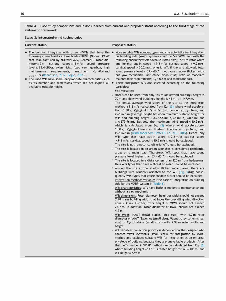
Table 4 Case study comparisons and lessons learned from current and proposed status according to the third stage of thesystematic framework.
Stage 3: Integrated-wind technologies
Current status Proposed status
� The building integrates with three HAWTs that have thefollowing characteristics: Five blades HAWT (Norwin 19 kWthat manufactured by NORWIN A/S, Denmark); rotor dia-meter=9 m; cut-out speed=16 m/s; sound pressurelevelr63.4 dB(A); avian risks; fixed yaw; gearbox; highmaintenance requirements; maximum Cp�0.4;andηgen�0.9 (Bennetsen, 2012; Bogle, 2011).
� The used WTs have some inappropriate characteristics suchas its number and dimensions which did not exploit allavailable suitable height.
� More suitable WTs number, types and characteristics for integrationon building side (WARP system) could be Six VAWT and with thefollowing characteristics: Savonius (small size); 7.98 m rotor widthand height; cut-in speed o9.2 m/s; cut-out speed 49.2 m/s;survival speed 430.2 m/s; on-grid WTs if the grid allowed; totalsound pressure level o53.4 dB(A); not cause shadow flicker; with-out yaw mechanism; not cause avian risks; little or moderatemaintenance requirements; Cp�0.54; and moderate cost.
� These integrated-WTs are selected according to the followingvariables:
– Site variables:○ HAWTs can be used from only 140 m (as upwind buildings' height is
70 m and downwind buildings' height is 45 m) till 147.9 m.○ The annual average wind speed of the site at the integration
methodE9.2 m/s (calculated from Eq. (3) where wind accelera-tion=1.80 V; VA(zA)=4 m/s in Brixton, London at zA=16 m; andz=126.5 m (average height between minimum suitable height forWTs and building height); d=52.5 m; z0=5 m; z0A=0.5 m; andδIE279.96 m). Besides, the maximum wind speedE30.2 m/s,which is calculated from Eq. (3) where wind acceleration=1.80 V; VA(zA)=13 m/s in Brixton, London at zA=16 m; andz=126.5 m (WindFinder.com GmbH & Co. KG., 2015). Hence, anyWTs type that have cut-in speed 49.2 m/s; cut-out speedo9.2 m/s; survival speed o30.2 m/s should be excluded.
○ The site is not remote, so off-grid WT should be excluded.○ The site is located in an urban type that is considered residential
areas on a main road. Therefore, WTs types that have soundpressure level higher than 53.4 dB(A) should be excluded.
○ The site is located in a distance less than 120 m from hedgerows,thus WTs types that have a threat to avian should be excluded.
○ Around the site at the shadow flicker impact area, there arebuildings with windows oriented to the WT (Fig. 5(b)); conse-quently WTs types that cause shadow flicker should be excluded.
– Integration methods variables (the case of integration on buildingside by the WARP system in Table 1):
○ WTs characteristics: WTs have little or moderate maintenance andwithout a yaw mechanism.
○ WTs dimensions: Rotor diameter, height or width should not exceed7.98 m (as building width that faces the prevailing wind directionequals 35 m). Further, rotor height of VAWT should not exceed25.7 m. In addition, rotor diameter of HAWT should not exceed4.7 m.
○ WTs types: HAWT (Multi blades (pico size)) with 4.7 m rotordiameter or VAWT (Savonius (small size), Magnetic levitation (smallsize) or Cycloturbine (small size)) with 7.98 m rotor width andheight.
– WT variables: Selection priority is depended on the designer whochooses VAWT (Savonius (small size)) for integration by WARPmethod and excludes suitable WTs for integration as an externalenvelope of building because they are unavailable products. Afterthat, WTs number in WARP method can be calculated from Eq. (6)where building height=147.9; suitable height for WT=105 m; andWT height=7.98 m.
A.A. ELMokadem et al.10

Fig. 8 Perspective view of the selected integration method ofWTs when applying the suggested framework on Strata SE1building.
11Systematic framework for the efficient integration of wind technologies into buildings
three cases. This efficient integration can be achieved,providing that this process is part of the building earlydesign phase. Furthermore, the general concluded guide-lines to design BIWT for higher energy production are:
� As a rule, the construction permitted height in thebuilding site should achieve the required conditions forsite suitability.
� Increasing either building height or building dimension whichfaces the prevailing wind flow means increasing the windexposed area that can be exploited for WTs integration. It isimportant to note that increasing the building height leadsto higher energy production from the WTs than increasingthe building dimension, which faces the prevailing wind flow.Thus, increasing the building height is considered the bestsolution to exploit the increase of both wind speed withheight and wind exposed façade that can be exploited forWTs integration.
� It is preferable to avoid, as much as possible, the increaseof building dimension which is in the same direction withthe prevailing wind flow because it increases the buildingenergy demand while not providing more wind exposedarea for WTs integration.
� In brief, WTs can integrate with any building type andshape because of the wide range of WTs and integrationmethods where the suitable ones for building can befound and selected.
Table 5 Case study comparisons and lessons learned from currsystematic framework.
Stage 4: Comparison between energy production and consum
Current status P
� The annual energy output of current integrated WTsE10,440kwh/yr, which is calculated from Eq. (7) where:
– PturbE2696.2 W, which is calculated from Eq. (9) where:○ ρ=1.212 kg/m3 (calculated from Eq. (10) where p=98865.2 Pa
and T=284.3 1K at 147.9 m (WindFinder.com GmbH & Co. KG.,2015))
○ Total A=190.9 m2 (calculated from Eq. (11) where r=4.5 m forthe current WT)
○ VavgE4.4 m/s calculated from Eq. (1) where wind accelera-tion=0.9 V; V(zref)=4 m/s at zref=93 m; d=52.5 m; z0=5 m;and z=147.9 m
○ Cp=0.4 for the current WTs○ ηt=0.684 (calculated by multiplying ηele=0.8, ηgen=0.9 and
ηgear=0.95 of the current WTs)– Vavg probability per yearE0.85 (calculated from Eq. (8) wherecut-in speed=2 m/s and cut-out speed=16 m/s for thecurrent WTs)
– Vavg probability at exploited wind directions (7451 from the SWwind direction)=0.52 (calculated from the wind rose diagram ofBrixton, London in Fig. 7).
� The annual energy consumption=625,000 kWh/yr when fullyoperational (BFLS, 2014).
� Based on the previous calculations, only 1.7% of annual energyconsumption can be provided by the current integrated-WTs.
�
–
○
○
○
○○
–
–
�
�
For presenting the results from the proposed framework,the site and building data in addition to the preferencemethods are required as follows:
� Site data: wind data, wind directions' distribution, pre-vailing vertical wind direction on site, obstacles height at
ent and proposed status according to the fourth stage of the
ption
roposed status
The proposed integrated-WTs can produce 612,768 kWh/yr,which is calculated from Eq. (7) where:PturbE74896.959 W, which is calculated from Eq. (9) where:ρ=1.214 kg/m3 (calculated from Eq. (10) where p=99,122 Paand T=284.4 1K at 126.5 m (WindFinder.com GmbH & Co. KG.,2015))Total A=382.1 m2 (calculated from Eq. (11) where D andH=7.98 m for each suggested WT)Vavg of the site at the integration methodE9.2 m/s (previouslycalculated in Table 4)Cp=0.54 for the suggested WTsηt=0.768 (calculated by multiplying ηele=0.8 and ηgen=0.96 ofthe suggested WTs).Vavg probability per yearE0.934 (calculated from Eq. (8)where cut-in speed=2 m/s and cut-out speed=25 m/s for thesuggested WTs)Vavg probability at exploited wind directions (all directions)=1(from the wind rose diagram of Brixton, London in Fig. 7).The annual energy consumption=625,000 kWh/yr when fullyoperational (BFLS, 2014).Based on the previous calculations, a 98% of annual energyconsumption can be provided by the proposed integrated-WTs.

Table 6 The results of comparison between current status and proposed integration of the case study buildings.
A.A. ELMokadem et al.12
13Systematic framework for the efficient integration of wind technologies into buildings
exploited wind directions within the determined upwindand downwind distance, urban type, distance fromelectricity grid, avian activities in surrounding site, theposition of city according to the equator and existing ofbuilding in the shadow flicker impact area.
� Building data: building dimensions (height, width anddepth), construction permitted height, building shapeconditions and either the total annual energy consump-tion or the area of each use in the building.
� Preference methods: determining a method to choosefrom suitable WTs and to compare energy productionfrom the WTs with energy consumption in the building.
A systematic framework for efficient integration of WTsinto a building has been proposed, and its effectiveness hasbeen assessed. Afterwards, this framework can aid archi-tects in order to gather scientific background related toBIWTs and ease architects' dealing with many charts,matrices, equations and other scientific data.
In a technical point of view, designing a comprehensivesystematic framework is such a complex task which requiresintegration of different disciplinary such as mechanical,electrical, structural as well as architectural point of view.However, the presented paper presents only the architec-tural point of view that may encourage other specialists toadd to the scientific knowledge. With further progress, oneshould anticipate the evolution of more scientific perspec-tive. The intended spirit of this perspective was not limited,but encourages new and different thinking that is steepedtowards a comprehensive systematic framework.
Acknowledgments
The authors would like to thank the reviewers for theirinsightful comments for the improvement of the manuscript.
References
Abohela, I., Hamza, N., Dudek, S., 2011. Urban wind turbinesintegration in the built form and environment. Newctle. Univ.Ej. 10, 23–39.
Al-Shemmeri, T., 2010. Wind Turbines, T. Al-Shemmeri & VentusPublishing ApS. Retrieved December 3, 2015, from the World WideWeb: /http://sietm.com/wp-content/uploads/2015/03/wind-turbines.pdfS, pp. 34–77.
American Wind Energy Association, 2003. Wind Energy Teacher'sGuide. American Wind Energy Association. U.S Department ofEnergy, Washington, USA, 3–4.
American Wind Energy Association, 2009. AWEA Small Wind TurbinePerformance and Safety Standard (AWEA 9.1). AWEA, Washing-ton, USA (Appendix A).
Beller, C., 2009. Urban Wind Energy – State of the Art 2009.Denmark: Risø National Laboratory for Sustainable Energy,Technical University of Denmark, Denmark, 15–30.
Bennetsen, J., 2012. Construction: High-Rise Wind Turbines. ANSYSAdvant. VI (1), 21–23.
Bogle Flanagan Lawrence Silver (BFLS), 2014. Strata SE1. Architec-ture News Plus. Retrieved December 3, 2015, from the WorldWide Web: ⟨http://www.architecturenewsplus.com/projects/1633⟩.
Bogle, I., 2011. Integrating wind turbines in tall buildings. Int. J.Tall Build. Urban Habitat (CTBUH) IV, 30–34.
Breshears, J., Briscoe, C., 2009. The informed application ofbuilding-integrated wind power. In: Proceedings of the 26thConference on Passive and Low Energy Architecture, QuebecCity, Canada. Laval University, Quebec City, Canada, (Section(3.3.6)).
Cace, J., Horst, E., Syngellakis, K., Niel, M., Clement, P., Heppener,R., Peirano, E., 2007. Guidelines for Small Wind Turbines in theBuilt Environment. European Commission. Retrieved December5, 2015, from the World Wide Web: ⟨http://www.urbanwind.net/pdf/SMALL_WIND_TURBINES_GUIDE_final.pdf⟩, pp. 27–33.
Council on Tall Buildings and Urban Habitat (CTBUH), 2014. Strata.CTBUH. Retrieved December 25, 2015, from the World Wide Web:⟨http://www.skyscrapercenter.com/london/strata/4131/⟩.
Dunster, B., 2006. SkyZED The Flower Tower. ZED Factory. RetrievedDecember 10, 2015, from the World Wide Web: ⟨http://www.soe-townsville.org/external_pages/SkyZED_The_Flower_Tower.html⟩.
Dutton, A., Halliday, J., Blanch, M., 2005. The feasibility ofbuilding-mounted/integrated wind turbines (BUWTs): achievingtheir potential for carbon emission reductions. Energy Res. UnitCCLRC Carbon Trust 73, 42–46.
Gadawski, A., Lynch, G., 2011. The Real Truth About Wind Energy: ALiterature Review on Wind Turbines in Ontario. Sierra ClubCanada, Ottawa, 24–29.
Giovanello, A., Kaplan, C., 2008. Wind Energy Siting Handbook.American Wind Energy Association, Washington, USA, 5.33–5.34.
Hughes, B., Chaudhry, H., 2011. Power Generation Potential ofDynamic Architecture. World Acad. Sci. Eng. Technol. 5,219–225.
Lysen, E., 1983. Introduction to Wind Energy. Netherlands: Con-sultancy Services, Wind Energy, Developing Countries (CWD),Netherlands, 21–50.
Masters, G., 2004. Renewable and Efficient Electric Power Systems.John Wiley & Sons, Inc, Hoboken, New Jersey, 312–367.
Mcguire, D., 2003. Small Wind Electric Systems: A Guide Producedfor the American Corn Growers Foundation. Energy Efficiencyand Renewable Energy, Wind and Hydropower TechnologiesProgram, U.S. Department of Energy, Washington, USA, 14–15.
Mertens, S., 2006. Wind Energy in the Built Environment: Concen-trator Effects of Buildings. Technische Universiteit Delft (TUDelft), Brentwood, Essex.
Minister of State for Environmental Affairs, 1994. The Environmen-tal Protection Law No. 4. Minister of State for EnvironmentalAffairs, Egypt, 52–55.
Noaman, D., 2012. Solar Energy as an Approach for SustainableArchitecture in Egypt (Case Study: Residential Buildings). PortSaid University, Egypt, 47.
Pennsylvania State University, 2014. Architectural and EngineeringData on Buildings with Integrated Wind Turbines: KINETICA. ThePennsylvania State University (Penn State). Retrieved December13, 2015, from the World Wide Web: ⟨http://www.wind.psu.edu/buildings/kinetica.asp⟩.
Renewable UK, 2010. Generate Your Own Power: Guide to Installinga Small Wind System. Renewable UK, London, UK, 9–11.
Sharpe, T., 2010. The Role of Aesthetics, Visual and PhysicalIntegration in Building Mounted Wind Turbines – An AlternativeApproach, Paths to Sustainable Energy, Dr Artie Ng (Ed.), ISBN:978-953-307-401-6, InTech, DOI: 10.5772/12837. RetrievedDecember 2, 2015, from the World Wide Web: ⟨http://www.intechopen.com/books/paths-to-sustainable-energy/the-role-of-aesthetics-visual-and-physical-integration-in-building-mounted-wind-turbines-an-alternat⟩.
Sivakumar, S., 2012. Building Envelope Wind Pressure Manipulationfor Application in Streamlined High-Rise Buildings. College ofEngineering and Computer Science, Syracuse University, NewYork, USA, 32.
Stankovic, S., Campbell, N., Harries, A., 2009. Urban wind energy.Earthscan, London, UK, 77–177.

A.A. ELMokadem et al.14
Syngellakis, K., Cace, J., Clement, P., 2007. Reports on thefeasibility study (D5.2). European Commission. RetrievedDecember 24, 2015, from the World Wide Web: ⟨http://www.urbanwind.net/pdf/Report_D52CombinedReport.PDF⟩, p. 32.
Syngellakis, K., Traylor, H., 2007. Urban Wind Resource Assessmentin the UK: An introduction to wind resource assessment in theurban environment (D5.1). European Commission. RetrievedDecember 5, 2015, from the World Wide Web: ⟨http://www.urban-wind.org/pdf/Reports_UrbanWindResourceAssessment_UK.pdf⟩, pp. 19–20.
Taylor, D., 2008. Low/Zero Carbon: Renewable Energy for Uttle-sford. Altechnica, UK, 51–53.
Tong, W., 2010. Wind Power Generation and Wind Turbine Design.WIT Press, WITeLibrary, 12–88.
Urge-Vorsatz, D., 2007. Climate change mitigation in the buildingssector: the findings of the 4th Assessment Report of the IPCC.
Center for Climate Change and Sustainable Energy, CentralEuropean University, Hungary, 4.
USA Humdinger Wind Energy LLC, 2015. Wind Technologies Pro-ducts. Retrieved December 1, 2015, from the World WideWeb: ⟨www.humdingerwind.com/⟩.
Weisbrich, A.L., Pucher, K., 1996. Computational Fluid DynamicAssessment of a WARP Wind Power System. American WindEnergy Association Conference (WINDPOWER'96), Denver, Color-ado, pp. 557–562.
WindFinder.com GmbH & Co. KG., 2015. Wind and weather statis-tics Brixton/London. WindFinder.com. Retrieved December 22,2015, from the World Wide Web: ⟨http://www.windfinder.com/windstatistics/brixton_london⟩.