System to Remotely Transport and Deploy an Unmanned Helicopter
22
1 System to Remotely Transport and Deploy an Unmanned Helicopter MEM Senior Design Team Number 10 Dr. Paul Y. Oh (Advisor) Jason Collins (MEM) Michael Perreca (ECE) Caitlyn Worthington-Kirsch (MEM) Drexel Autonomous Systems Laboratory (D.A.S.L.) March 5, 2008
-
Upload
kathleen-patterson -
Category
Documents
-
view
32 -
download
0
description
System to Remotely Transport and Deploy an Unmanned Helicopter. MEM Senior Design Team Number 10. Dr. Paul Y. Oh (Advisor) Jason Collins (MEM) Michael Perreca (ECE) Caitlyn Worthington-Kirsch (MEM) Drexel Autonomous Systems Laboratory (D.A.S.L.) March 5, 2008. Overview. - PowerPoint PPT Presentation
Transcript of System to Remotely Transport and Deploy an Unmanned Helicopter

1
System to Remotely Transport
and Deploy an Unmanned Helicopter
MEM Senior Design Team Number 10
Dr. Paul Y. Oh (Advisor)
Jason Collins (MEM)
Michael Perreca (ECE)
Caitlyn Worthington-Kirsch (MEM)
Drexel Autonomous Systems Laboratory (D.A.S.L.)
March 5, 2008

2
Overview
-Hazardous site rescue effort
-UAV provide observational platform during “Golden Hour”-Not interfere with existing rescue efforts-Rapid unmanned transport and deployment-Adapt to dynamic situation
-Current mission plan gap:Unmanned transport and deployment of UAV systems
http://www.viewimages.com/Search.aspx?mid=51919023&epmid=1&partner=Google
http://newsimg.bbc.co.uk/media/images/44194000/jpg/_44194534_afp203bodybonita.jpg
Goal: Design trailer to carry UAV to scene
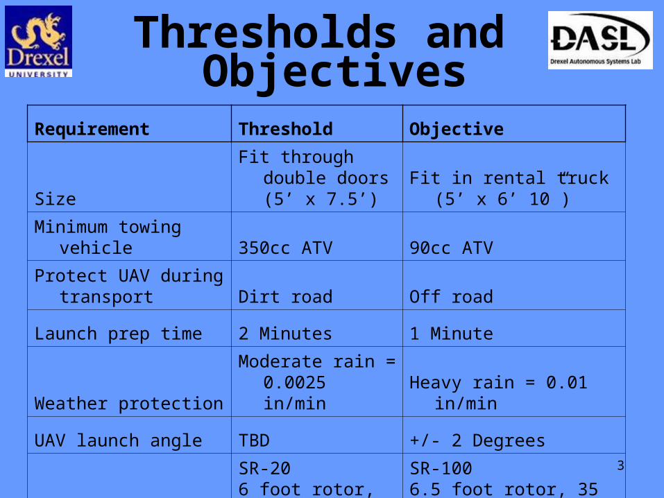
3
Thresholds and
Requirement Threshold Objective
SizeFit through double
doors (5’ x 7.5’)Fit in rental truck (5’ x 6’
10”)
Minimum towing vehicle 350cc ATV 90cc ATV
Protect UAV during transport Dirt road Off road
Launch prep time 2 Minutes 1 Minute
Weather protectionModerate rain =
0.0025 in/min Heavy rain = 0.01 in/min
UAV launch angle TBD +/- 2 Degrees
UAV typeSR-20 6 foot rotor, 21 lbs
SR-1006.5 foot rotor, 35 lbs
Objectives
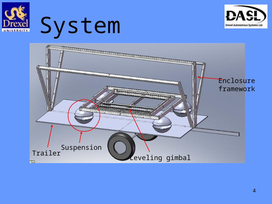
4
System Overview
Enclosure framework
Leveling gimbal
SuspensionTrailer

5
Deliverables-Leveling system
-Data Acquisition and
Actuation Electronics
-Suspension system
-Enclosed Trailer
-Testing Results
-Final Design Report

6
Leveling System
Proposed Solution-Gimbal system to level platform
-Breaks to dampen oscillation
-Bump stops to prevent over travelGimbal Demonstrator Natural Response
-40
-20
0
20
40
0
0.3
3
0.6
6
0.9
9
1.3
2
1.6
5
1.9
8
2.3
1
2.6
4
2.9
7
3.3
3.6
3
3.9
6
4.2
9
Time in seconds
De
gre
es
Roll
Pitch

7
Leveling System
ProgressGimbal is constructed and able to safely support helicopter

8
Braking Setback
Original gimbal brakes too expensive and overdesigned
We solved this by using caliper brakes adapted from a bicycle

9
Latch Design
The design for the latch to hold the helicopter on the gimbal during transit had been discussed in the fall term but not refined
This term the design was refined and the latch built

10
Dampening System
Initial design: a classic spring-dashpot system
Only moves along one axis
Allowing sideways movement - unstable
Multiple systems for different axes – too complex
A compressible sphere moves on all axes and is simple, but still unstable
Bowls made the ball design stable and adaptable
Design

11
Dampening System
Proposed Solution
Proof-of-concept
Compressible ball between two bowls
Allows for sideways and twisting movement
Transference of approximately 5% of vibration at 5 Hz
Tunable for varying conditions by inflating and deflating ball
Cad model

12
Dampening System
Progress
Dampening System built and installed
Initial qualitative tests were successful

13
Overall Mechanical Progress
Trailer is almost ready for testing
Still need to finish the enclosure

National Instruments Compact RIO
Data Acquisition andActuation Electronics
NI Compact RIO
NI 9205
-32 Analog Input Channels
- ±200mV - ± 10V Input Ranges
-16-bit resolution; 250 kS/s aggregate sampling rate
NI 9476- 32 Channel Voltage Sourcing Output
-250mA supply/channel
-6-36V output range

Data Acquisition andActuation Electronics
Actuation Wiring
-2 SPDT Bosch-Style 30 Amp Relays
-Wired in an H-Bridge configuration
-Allows for positive and negative direction actuation
-Low current needed to trigger relays
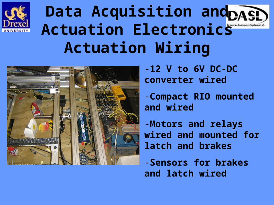
Data Acquisition andActuation Electronics
Actuation Wiring-12 V to 6V DC-DC converter wired
-Compact RIO mounted and wired
-Motors and relays wired and mounted for latch and brakes
-Sensors for brakes and latch wired
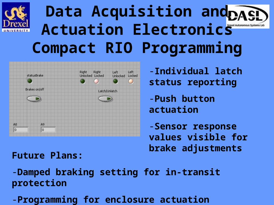
Data Acquisition andActuation Electronics
Compact RIO Programming-Individual latch status reporting
-Push button actuation
-Sensor response values visible for brake adjustments
Future Plans:
-Damped braking setting for in-transit protection
-Programming for enclosure actuation

18
Timeline
Mar 25 – Enclosure completed
Mar 29 – Actuation electronics completed
Mar 31 – Full trailer testing begins
May 5 – Final report and end of project

19
Budget
Total project expenses, including salaries: $105,000
Total approved budget: $8128.55
Expenditures to Date:8020 stock $1,463.71 8020 fasteners $932.28 other hardware $1,031.74 actuators $614.46 Electrical $848.72 NI $282.54 trailer $820 total $5,993.45
Anticipated future spending: $1000

20
Acknowledgements
Dr. Paul Y. Oh
D.A.S.L. Members
MEM Senior Design Committee
ECE Senior Design Committee
All Those in Attendance

21
Thank YouQuestions?
?

22
Gantt Chart