
System Planning, Design, Construction, and Protectionpuc.nh.gov/2008IceStorm/Final...
37
DECEMBER 2008 ICE STORM Chapter IV - System Planning, Design, Construction, and Protection NEI Electric Power Engineering Page IV-1 CHAPTER IV System Planning, Design, Construction, and Protection Chapter Structure Chapter IV.................................................................................................................................. IV-1 Chapter Structure ............................................................................................................... IV-1 A. Background ................................................................................................................. IV-1 Transmission and Distribution ........................................................................................... IV-1 Transmission System ......................................................................................................... IV-2 Sub-Transmission System.................................................................................................. IV-4 Distribution System ........................................................................................................... IV-5 Electric Distribution Substations ....................................................................................... IV-7 Transmission System Protection ........................................................................................ IV-8 Distribution System Protection .......................................................................................... IV-9 Substation Protection ......................................................................................................... IV-9 SCADA ............................................................................................................................ IV-10 Covered Wire ................................................................................................................... IV-10 Pole Construction and Loading........................................................................................ IV-11 B. Evaluative Criteria..................................................................................................... IV-12 C. Tasks.......................................................................................................................... IV-19 D. Findings and Conclusions ......................................................................................... IV-19 A. BACKGROUND Transmission and Distribution The December 2008 ice storm caused extensive power outages throughout the state of New Hampshire. Since the backbone of any electric system involves the transmission system, a review was made of the transmission systems that support PSNH, Unitil, National Grid, and NHEC in order to ascertain how they were affected by the ice storm. In New Hampshire, transmission voltage levels begin at 69 kV. Voltages below 69 kV are typically categorized as distribution. While states may have laws or regulations that influence the transmission system, the reliability criteria for transmission systems are normally dictated by federal agencies such as the Federal Energy Regulatory Commission (FERC) and the North American Electric Reliability Corporation (NERC). In most cases, transmission systems are designed, constructed, protected, and operated with higher utility industry standards than distribution systems. The reliability criteria applicable to most transmission lines require that the loss of a single transmission line
Transcript of System Planning, Design, Construction, and Protectionpuc.nh.gov/2008IceStorm/Final...
DECEMBER 2008 ICE STORM Chapter IV - System Planning, Design, Construction, and Protection
NEI Electric Power Engineering Page IV-1
CHAPTER IV
System Planning, Design, Construction, and Protection
Chapter Structure Chapter IV..................................................................................................................................IV-1
Chapter Structure ...............................................................................................................IV-1 A. Background .................................................................................................................IV-1
Transmission and Distribution...........................................................................................IV-1 Transmission System .........................................................................................................IV-2 Sub-Transmission System..................................................................................................IV-4 Distribution System ...........................................................................................................IV-5 Electric Distribution Substations .......................................................................................IV-7 Transmission System Protection........................................................................................IV-8 Distribution System Protection..........................................................................................IV-9 Substation Protection .........................................................................................................IV-9 SCADA............................................................................................................................IV-10 Covered Wire ...................................................................................................................IV-10 Pole Construction and Loading........................................................................................IV-11
B. Evaluative Criteria.....................................................................................................IV-12 C. Tasks..........................................................................................................................IV-19 D. Findings and Conclusions .........................................................................................IV-19
A. BACKGROUND
Transmission and Distribution
The December 2008 ice storm caused extensive power outages throughout the state of New Hampshire. Since the backbone of any electric system involves the transmission system, a review was made of the transmission systems that support PSNH, Unitil, National Grid, and NHEC in order to ascertain how they were affected by the ice storm. In New Hampshire, transmission voltage levels begin at 69 kV. Voltages below 69 kV are typically categorized as distribution.
While states may have laws or regulations that influence the transmission system, the reliability criteria for transmission systems are normally dictated by federal agencies such as the Federal Energy Regulatory Commission (FERC) and the North American Electric Reliability Corporation (NERC). In most cases, transmission systems are designed, constructed, protected, and operated with higher utility industry standards than distribution systems. The reliability criteria applicable to most transmission lines require that the loss of a single transmission line
DECEMBER 2008 ICE STORM Chapter IV - System Planning, Design, Construction, and Protection
NEI Electric Power Engineering Page IV-2
will not result in an outage to customers. Additional distinctions between the transmission and distribution systems and the sub-transmission system are discussed below.
Transmission System
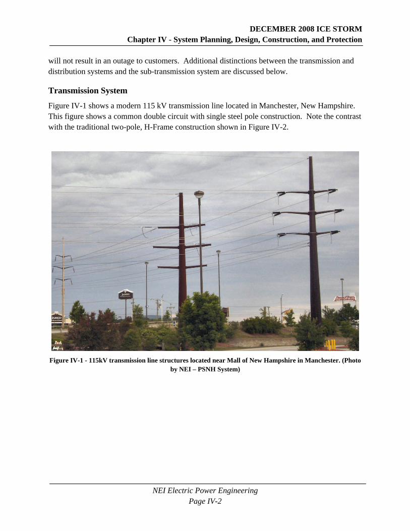
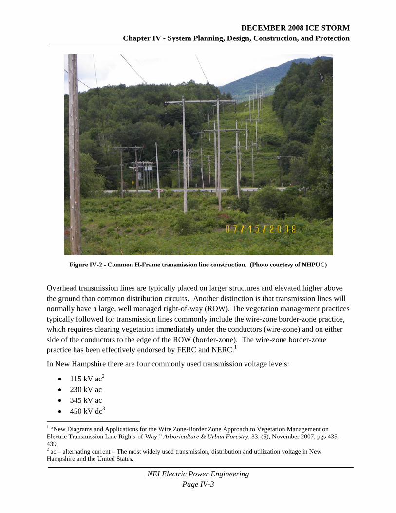
Figure IV-1 shows a modern 115 kV transmission line located in Manchester, New Hampshire. This figure shows a common double circuit with single steel pole construction. Note the contrast with the traditional two-pole, H-Frame construction shown in Figure IV-2.
Figure IV-1 - 115kV transmission line structures located near Mall of New Hampshire in Manchester. (Photo
by NEI – PSNH System)
DECEMBER 2008 ICE STORM Chapter IV - System Planning, Design, Construction, and Protection
NEI Electric Power Engineering Page IV-3
Figure IV-2 - Common H-Frame transmission line construction. (Photo courtesy of NHPUC)
Overhead transmission lines are typically placed on larger structures and elevated higher above the ground than common distribution circuits. Another distinction is that transmission lines will normally have a large, well managed right-of-way (ROW). The vegetation management practices typically followed for transmission lines commonly include the wire-zone border-zone practice, which requires clearing vegetation immediately under the conductors (wire-zone) and on either side of the conductors to the edge of the ROW (border-zone). The wire-zone border-zone practice has been effectively endorsed by FERC and NERC.1
In New Hampshire there are four commonly used transmission voltage levels:
• 115 kV ac2 • 230 kV ac • 345 kV ac • 450 kV dc3
1 “New Diagrams and Applications for the Wire Zone-Border Zone Approach to Vegetation Management on Electric Transmission Line Rights-of-Way.” Arboriculture & Urban Forestry, 33, (6), November 2007, pgs 435-439. 2 ac – alternating current – The most widely used transmission, distribution and utilization voltage in New Hampshire and the United States.
DECEMBER 2008 ICE STORM Chapter IV - System Planning, Design, Construction, and Protection
NEI Electric Power Engineering Page IV-4
The 115 kV voltage level is commonly used to deliver power to sub-transmission systems and distribution substations. The 230 kV and 345 kV voltage levels are commonly used to deliver bulk power to transmission and sub-transmission substations. Systems operating at 450 kV dc are used to transfer bulk power through the state of New Hampshire and are not presently used to directly serve loads.
During the December 2008 ice storm, the transmission system received relatively minor damage and resulted in a single power outage to one substation that supplies approximately 5,400 customers in the Pelham area.
Sub-Transmission System
Technically the utility industry defines only two systems: transmission and distribution. In practice, however, a third system exists. It is considered a distribution system, but operates similarly to a transmission system by delivering power to distribution substations. This system is identified as the sub-transmission system. The sub-transmission system is used to supply power and energy to electric substations, but is not planned, designed, and constructed to the same utility industry standards as the transmission system. While the sub-transmission system may operate at voltages from approximately 15 kV through 138 kV, the sub-transmission systems in New Hampshire are primarily operated at 34.5 kV, with some 23 kV and 46 kV systems. During the December 2008 ice storm, the electric sub-transmission systems of New Hampshire received heavy damage primarily from ice laden limbs and trees falling onto sub-transmission power lines.
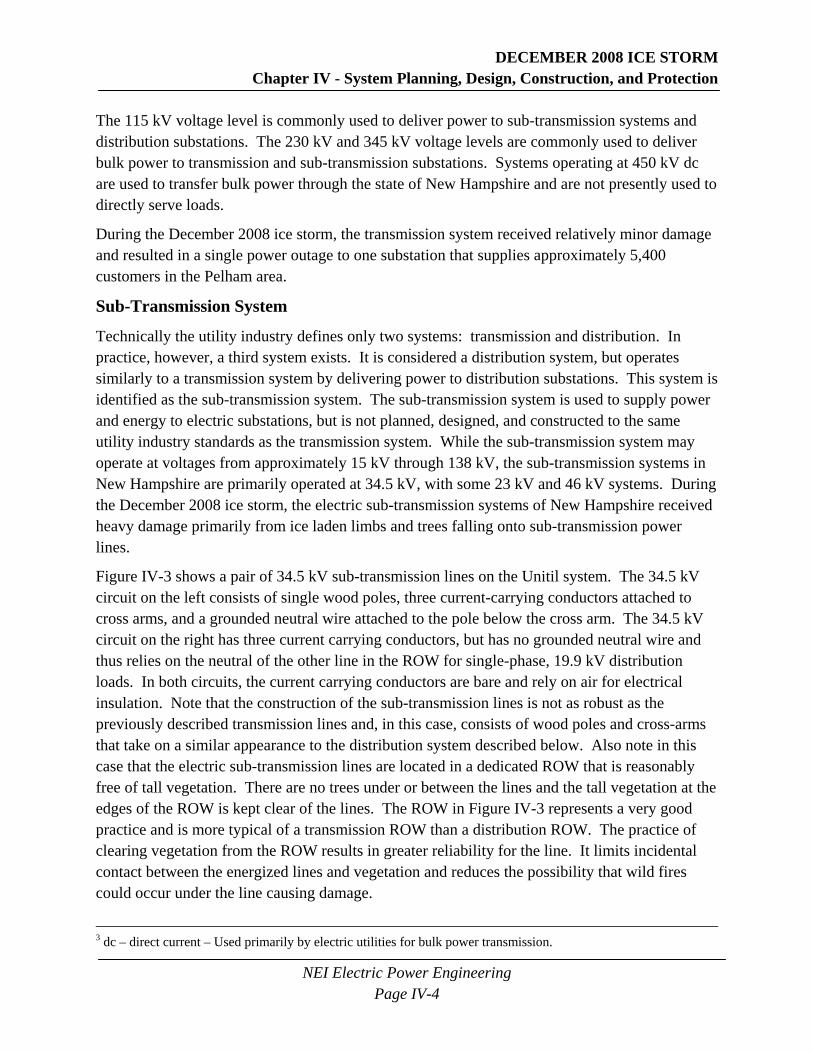
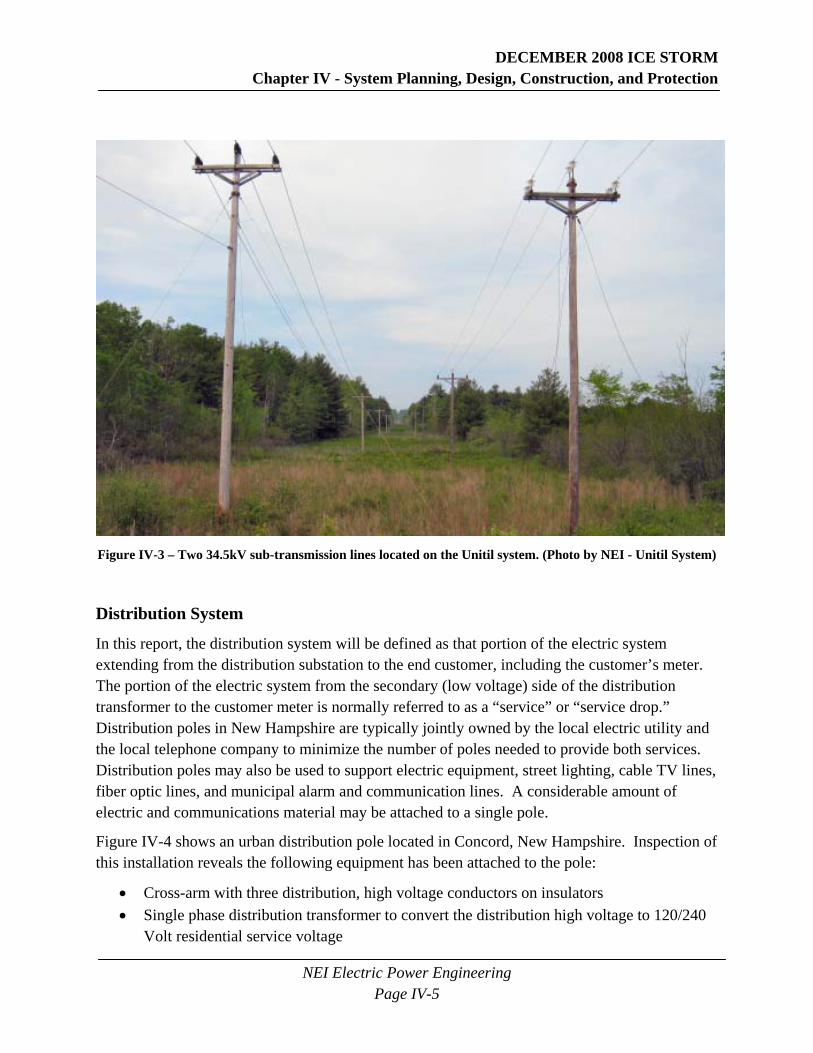
Figure IV-3 shows a pair of 34.5 kV sub-transmission lines on the Unitil system. The 34.5 kV circuit on the left consists of single wood poles, three current-carrying conductors attached to cross arms, and a grounded neutral wire attached to the pole below the cross arm. The 34.5 kV circuit on the right has three current carrying conductors, but has no grounded neutral wire and thus relies on the neutral of the other line in the ROW for single-phase, 19.9 kV distribution loads. In both circuits, the current carrying conductors are bare and rely on air for electrical insulation. Note that the construction of the sub-transmission lines is not as robust as the previously described transmission lines and, in this case, consists of wood poles and cross-arms that take on a similar appearance to the distribution system described below. Also note in this case that the electric sub-transmission lines are located in a dedicated ROW that is reasonably free of tall vegetation. There are no trees under or between the lines and the tall vegetation at the edges of the ROW is kept clear of the lines. The ROW in Figure IV-3 represents a very good practice and is more typical of a transmission ROW than a distribution ROW. The practice of clearing vegetation from the ROW results in greater reliability for the line. It limits incidental contact between the energized lines and vegetation and reduces the possibility that wild fires could occur under the line causing damage.
3 dc – direct current – Used primarily by electric utilities for bulk power transmission.
DECEMBER 2008 ICE STORM Chapter IV - System Planning, Design, Construction, and Protection
NEI Electric Power Engineering Page IV-5
Figure IV-3 – Two 34.5kV sub-transmission lines located on the Unitil system. (Photo by NEI - Unitil System)
Distribution System
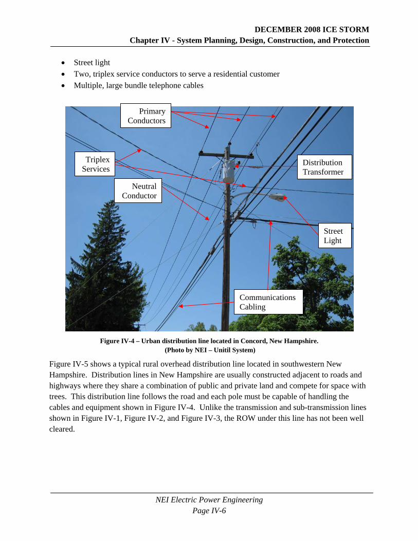
In this report, the distribution system will be defined as that portion of the electric system extending from the distribution substation to the end customer, including the customer’s meter. The portion of the electric system from the secondary (low voltage) side of the distribution transformer to the customer meter is normally referred to as a “service” or “service drop.” Distribution poles in New Hampshire are typically jointly owned by the local electric utility and the local telephone company to minimize the number of poles needed to provide both services. Distribution poles may also be used to support electric equipment, street lighting, cable TV lines, fiber optic lines, and municipal alarm and communication lines. A considerable amount of electric and communications material may be attached to a single pole.
Figure IV-4 shows an urban distribution pole located in Concord, New Hampshire. Inspection of this installation reveals the following equipment has been attached to the pole:
• Cross-arm with three distribution, high voltage conductors on insulators • Single phase distribution transformer to convert the distribution high voltage to 120/240
Volt residential service voltage
DECEMBER 2008 ICE STORM Chapter IV - System Planning, Design, Construction, and Protection
NEI Electric Power Engineering Page IV-6
• Street light • Two, triplex service conductors to serve a residential customer • Multiple, large bundle telephone cables
Figure IV-4 – Urban distribution line located in Concord, New Hampshire.
(Photo by NEI – Unitil System)
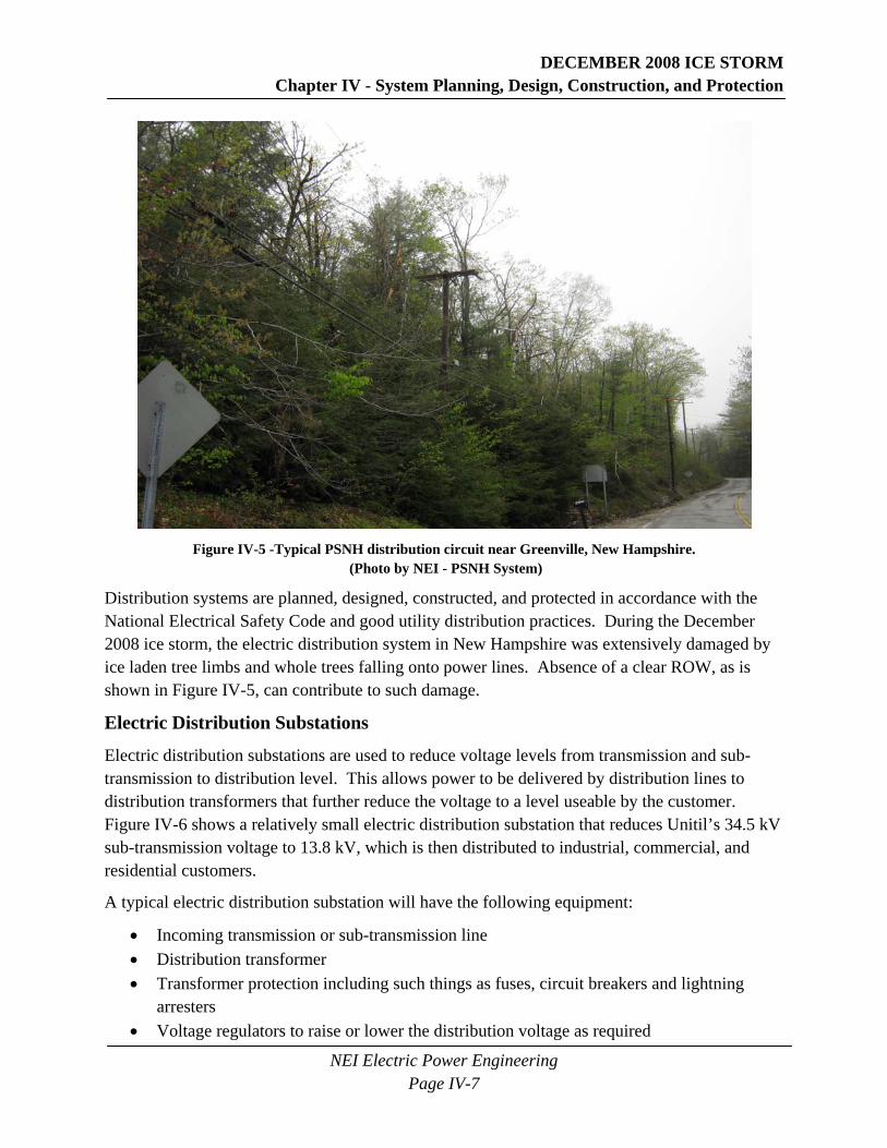
Figure IV-5 shows a typical rural overhead distribution line located in southwestern New Hampshire. Distribution lines in New Hampshire are usually constructed adjacent to roads and highways where they share a combination of public and private land and compete for space with trees. This distribution line follows the road and each pole must be capable of handling the cables and equipment shown in Figure IV-4. Unlike the transmission and sub-transmission lines shown in Figure IV-1, Figure IV-2, and Figure IV-3, the ROW under this line has not been well cleared.
Communications Cabling
Primary Conductors
Neutral Conductor
Triplex Services
Street Light
Distribution Transformer
DECEMBER 2008 ICE STORM Chapter IV - System Planning, Design, Construction, and Protection
NEI Electric Power Engineering Page IV-7
Figure IV-5 -Typical PSNH distribution circuit near Greenville, New Hampshire.
(Photo by NEI - PSNH System)
Distribution systems are planned, designed, constructed, and protected in accordance with the National Electrical Safety Code and good utility distribution practices. During the December 2008 ice storm, the electric distribution system in New Hampshire was extensively damaged by ice laden tree limbs and whole trees falling onto power lines. Absence of a clear ROW, as is shown in Figure IV-5, can contribute to such damage.
Electric Distribution Substations
Electric distribution substations are used to reduce voltage levels from transmission and sub-transmission to distribution level. This allows power to be delivered by distribution lines to distribution transformers that further reduce the voltage to a level useable by the customer. Figure IV-6 shows a relatively small electric distribution substation that reduces Unitil’s 34.5 kV sub-transmission voltage to 13.8 kV, which is then distributed to industrial, commercial, and residential customers.
A typical electric distribution substation will have the following equipment:
• Incoming transmission or sub-transmission line • Distribution transformer • Transformer protection including such things as fuses, circuit breakers and lightning
arresters • Voltage regulators to raise or lower the distribution voltage as required

DECEMBER 2008 ICE STORM Chapter IV - System Planning, Design, Construction, and Protection
NEI Electric Power Engineering Page IV-8
• Electric outgoing distribution circuits complete with metering and circuit protection as circuit breakers or reclosers
• A substation fence for safety and security purposes
Figure IV-6 – 34.5kV to 13.8kV Unitil electric distribution substation located in
East Kingston, New Hampshire. (Photo by NEI-Unitil System)
During the December 2008 ice storm, the electric distribution substations were affected mainly by external causes, with minimal internal problems. Electric distribution substations lost power due to tree limbs and trees falling onto incoming power lines. The resultant damage caused circuit breakers and reclosers to open upstream from the substations to disconnect the damaged lines. In most cases, equipment located inside the electric distribution substations was unaffected, except for the normal operation of circuit breakers due to problems occurring outside of the substation.
Transmission System Protection
Transmission systems are typically constructed and protected as a network system4 such that a faulted (short circuited) section of the system can be isolated without causing interruption of 4 Network system – An electric system that has at least two sources (lines) of power supply such that the loss of one line will not result in loss of power to an electric customer.
DECEMBER 2008 ICE STORM Chapter IV - System Planning, Design, Construction, and Protection
NEI Electric Power Engineering Page IV-9
power to a customer. Transmission system protection includes not just the protection of the transmission lines, but also the generators, transformers, and substation buses that complete the transmission system. However, for the purpose of this report, the focus on transmission system protection will be limited to the protection of the transmission lines. (See Appendix E for a more thorough and technical discussion of transmission system protection.)
Distribution System Protection
Electric distribution systems, including those in New Hampshire, are typically radial systems, which means that the lines originating at the substation radiate outward toward their loads. The radial power lines normally have multiple taps from the main feeder, called laterals, which provide power to individual customers. The distribution system protection consists of feeder breakers with relay controls, feeder reclosers possibly both inside and outside of the substation, line sectionalizers, and line fuses. In the case of a large weather event, such as the December 2008 ice storm, a majority of the distribution system may be affected. As a large storm event develops, more and more of the distribution system, including main distribution lines, will experience permanent faults. This results in the loss of the ability to effectively sectionalize a distribution line or restore power through automatic reclosing. During the early hours of the December 2008 ice storm, the distribution system protection performed as expected by removing permanently faulted sections of line and restoring power through automatic reclosing for temporary faults. As the damage from the storm increased, the distribution system protection continued to perform as expected by disconnecting lines as they were damaged, causing more and more customers to be without power. (See Appendix E for a more thorough and technical explanation on distribution system protection.)
Substation Protection
The degree of substation protection is often determined by the size and importance of the substation itself as it relates to the power system. Normally, higher voltage substations and larger transformer sizes require more intricate protection schemes, whereas smaller substations may only require minimal protection, such as fuses. (See Appendix E for a more thorough and technical discussion on substation protection.)
DECEMBER 2008 ICE STORM Chapter IV - System Planning, Design, Construction, and Protection
NEI Electric Power Engineering Page IV-10
SCADA
Supervisory control and data acquisition (SCADA) systems are used to collect real-time information about the power system and provide control of system equipment. SCADA provides a centralized master station with information from substations and equipment in the field. The information collected can help in load management, provide important information on the health of the power system, and help determine the location of damaged lines and equipment. SCADA systems also make it possible for equipment in substations and in the field to be operated remotely to provide voltage control, switching for maintenance and repair work, and rerouting of power around faulted sections of lines.
Covered Wire
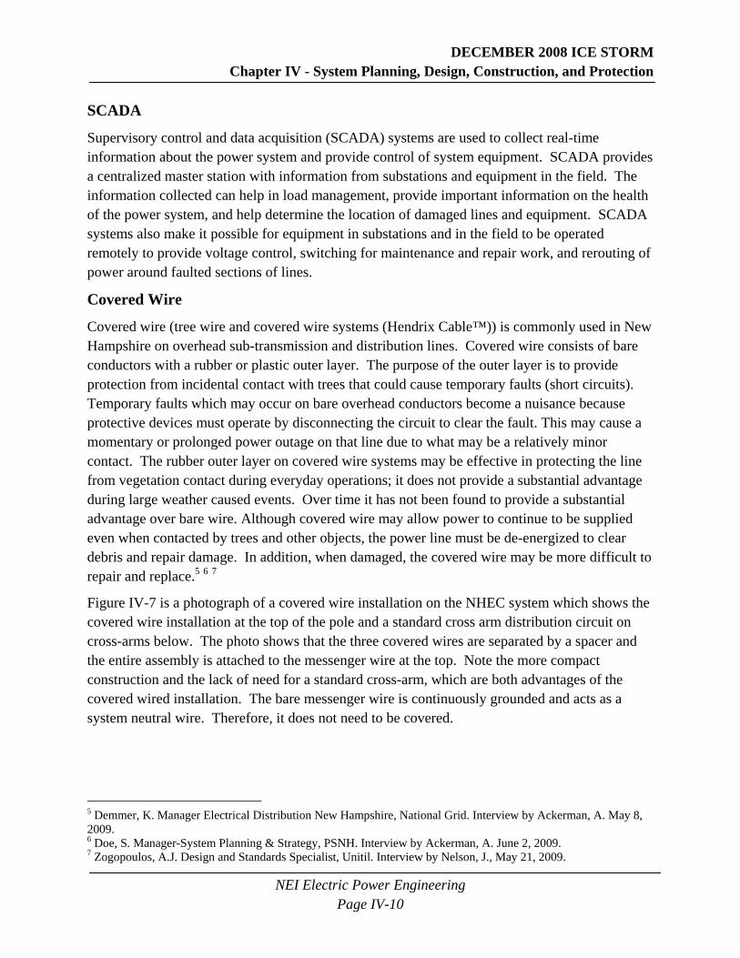
Covered wire (tree wire and covered wire systems (Hendrix Cable™)) is commonly used in New Hampshire on overhead sub-transmission and distribution lines. Covered wire consists of bare conductors with a rubber or plastic outer layer. The purpose of the outer layer is to provide protection from incidental contact with trees that could cause temporary faults (short circuits). Temporary faults which may occur on bare overhead conductors become a nuisance because protective devices must operate by disconnecting the circuit to clear the fault. This may cause a momentary or prolonged power outage on that line due to what may be a relatively minor contact. The rubber outer layer on covered wire systems may be effective in protecting the line from vegetation contact during everyday operations; it does not provide a substantial advantage during large weather caused events. Over time it has not been found to provide a substantial advantage over bare wire. Although covered wire may allow power to continue to be supplied even when contacted by trees and other objects, the power line must be de-energized to clear debris and repair damage. In addition, when damaged, the covered wire may be more difficult to repair and replace.5 6 7
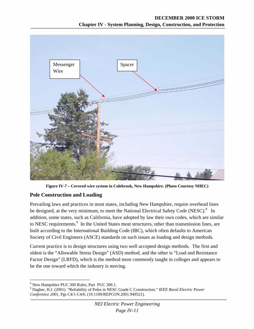
Figure IV-7 is a photograph of a covered wire installation on the NHEC system which shows the covered wire installation at the top of the pole and a standard cross arm distribution circuit on cross-arms below. The photo shows that the three covered wires are separated by a spacer and the entire assembly is attached to the messenger wire at the top. Note the more compact construction and the lack of need for a standard cross-arm, which are both advantages of the covered wired installation. The bare messenger wire is continuously grounded and acts as a system neutral wire. Therefore, it does not need to be covered.
5 Demmer, K. Manager Electrical Distribution New Hampshire, National Grid. Interview by Ackerman, A. May 8, 2009. 6 Doe, S. Manager-System Planning & Strategy, PSNH. Interview by Ackerman, A. June 2, 2009. 7 Zogopoulos, A.J. Design and Standards Specialist, Unitil. Interview by Nelson, J., May 21, 2009.
DECEMBER 2008 ICE STORM Chapter IV - System Planning, Design, Construction, and Protection
NEI Electric Power Engineering Page IV-11
Figure IV-7 – Covered wire system in Colebrook, New Hampshire. (Photo Courtesy NHEC)
Pole Construction and Loading
Prevailing laws and practices in most states, including New Hampshire, require overhead lines be designed, at the very minimum, to meet the National Electrical Safety Code (NESC).8 In addition, some states, such as California, have adopted by law their own codes, which are similar to NESC requirements.9 In the United States most structures, other than transmission lines, are built according to the International Building Code (IBC), which often defaults to American Society of Civil Engineers (ASCE) standards on such issues as loading and design methods.
Current practice is to design structures using two well accepted design methods. The first and oldest is the “Allowable Stress Design” (ASD) method, and the other is “Load and Resistance Factor Design” (LRFD), which is the method most commonly taught in colleges and appears to be the one toward which the industry is moving.
8 New Hampshire PUC 300 Rules, Part PUC 306.1. 9 Dagher, H.J. (2001). “Reliability of Poles in NESC Grade C Construction.” IEEE Rural Electric Power Conference 2001, Pgs C4/1-C4/6. (10.1109/REPCON.2001.949521).
SpacerMessenger Wire
DECEMBER 2008 ICE STORM Chapter IV - System Planning, Design, Construction, and Protection
NEI Electric Power Engineering Page IV-12
The NESC, however, uses neither of these commonly accepted methods. Instead it historically used an ultimate stress design method with overload factors included to provide the needed factors of safety. The NESC method differs from all other commonly accepted design methods, and loading requirements contained in the NESC are different than those used in any other code. NESC rules for selection of design loads and for safety factors are largely based on successful experience, but have little basis in theory.10 The more modern methods of design such as LRFD have been developed using successful experience as well as structural theory that has become accepted over the years. As a result, the NESC in recent editions has begun to gradually move toward the methods commonly accepted for other types of construction. The NESC should be considered in process of transition, and its requirements do not closely match the requirements that would be necessary to build a habitable structure.
The load and strength factors used in the 2007 version of the NESC are designed for use with both traditional NESC district loading and 50 years recurrence loading as shown in ASCE Standard 7 maps (See Figures F-2 and F-3 in Appendix F). Even though only NESC district loading cases are required for structures less than 60 feet, it is recommended that the higher wind and ice loading cases required by ASCE data also be taken into account for the design of all structures no matter their height. This approach should produce a more realistic design than the NESC district loading cases alone for the conditions that can be expected in New Hampshire. This would include determining from local sources the actual wind and ice loads that can be expected in the special wind areas shown on ASCE maps, rather than relying on loading data from NESC maps (See Appendix F for a more thorough and technical discussion on pole construction and loading as well as ASCE Standard 7 maps).
B. EVALUATIVE CRITERIA Prior to the December 2008 ice storm, each utility should have been planning, designing, and developing electrical system protection schemes in order to maximize reliability of its system during an abnormal event. The following criteria were used to assess each utility:
1. The transmission and sub-transmission system should be properly planned, designed, constructed, and protected.
2. The distribution system should be properly planned, designed, constructed, and protected.
3. Substations should be properly planned, designed, constructed, and protected.
1. The transmission and sub-transmission system should be properly planned, designed, constructed, and protected.
10 Bingel, Nelson and Dagher, Habib, et.al. (2003). “Structural Reliability-Based Design of Utility Poles and the National Electrical Safety Code.” Transmission and Distribution Conference and Exposition 2003, Vol. 3, Pgs 1088-1093. (10.1109/TDC.2003.1335100).
DECEMBER 2008 ICE STORM Chapter IV - System Planning, Design, Construction, and Protection
NEI Electric Power Engineering Page IV-13
• The correct ice and wind loading conditions should have been used during design. • The proper criteria should be used to determine when to replace and upgrade aging
equipment. • Aging equipment should not have had an adverse impact on the system during the storm. • The utility should have adequate planning and engineering staff to perform all necessary
planning, design, and protection work in a timely fashion. • The system should be designed and constructed to handle expected extreme weather
conditions. • The protection systems should be well designed, coordinated, and maintained. • Reasonable planning, design, protection, and construction budgets should be available in
order to maintain and operate the existing system and to design and build new parts as needed.
2. The distribution system should be properly planned, designed, constructed, and protected.
• Distribution lines and equipment should be properly designed. • The correct wind and ice loading criteria should be used in planning and design. • The proper criteria should be used to determine when to replace and upgrade aging
equipment. • Aging equipment should not have had an adverse impact on the system during the storm. • Proper planning for distribution line sectionalizing should exist. • The utility should have adequate planning and engineering staff to perform all necessary
planning, design, and protection work in a timely fashion. • The protection systems should be well designed, coordinated, and maintained. • Reasonable planning, design, protection, and construction budgets should be available in
order to maintain and operate the existing system and to design and build new parts as needed.
3. Substations should be properly planned, designed, constructed, and protected.
• Substations should be adequately planned and constructed to serve the loads under various system conditions.
• Substations should not have been adversely impacted during the storm. • The proper criteria should be used to determine when to replace and upgrade aging
equipment. • Aging equipment should not have had an adverse impact on the system during the storm. • The utility should have adequate planning and engineering staff to perform all necessary
planning, design, and protection work in a timely fashion. • Substations should be well designed and constructed to handle expected extreme weather
conditions.

DECEMBER 2008 ICE STORM Chapter IV - System Planning, Design, Construction, and Protection
NEI Electric Power Engineering Page IV-14
• The protection systems should be well designed, coordinated, and maintained. • Reasonable planning, design protection, and construction budgets should be available in
order to maintain and operate the existing system and to design and build new parts as needed.
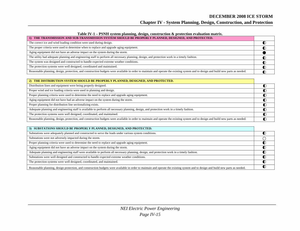
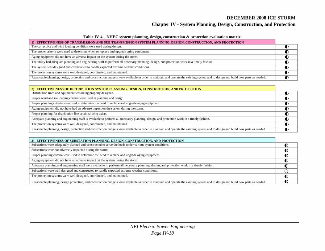
The following tables indicate the extent to which each of the utilities met the above criteria. These tables were not prepared to compare one utility with another. The utilities are very different, face different problems, and experienced different amounts of damage to their systems. These tables were prepared to show where each utility may improve its performance in preparation for the next storm or other disaster. A further explanation for the improvements that are recommended to each of the utilities may be found in the findings and conclusions section of this report. The meanings of the symbols used in the tables are:
Improvement is needed as stated in the report
Adequate with minor improvements suggested as stated in the report
Effective with no improvements noted.
DECEMBER 2008 ICE STORM Chapter IV - System Planning, Design, Construction, and Protection
NEI Electric Power Engineering Page IV-15
Table IV-1 – PSNH system planning, design, construction & protection evaluation matrix. 1) THE TRANSMISSION AND SUB-TRANSMISSION SYSTEM SHOULD BE PROPERLY PLANNED, DESIGNED, AND PROTECTED. The correct ice and wind loading condition were used during design.
The proper criteria were used to determine when to replace and upgrade aging equipment. Aging equipment did not have an adverse impact on the system during the storm. The utility had adequate planning and engineering staff to perform all necessary planning, design, and protection work in a timely fashion. The system was designed and constructed to handle expected extreme weather conditions. The protection systems were well designed, coordinated and maintained. Reasonable planning, design, protection, and construction budgets were available in order to maintain and operate the existing system and to design and build new parts as needed.
2) THE DISTRIBUTION SYSTEM SHOULD BE PROPERLY PLANNED, DESIGNED, AND PROTECTED. Distribution lines and equipment were being properly designed. Proper wind and ice loading criteria were used in planning and design. Proper planning criteria were used to determine the need to replace and upgrade aging equipment. Aging equipment did not have had an adverse impact on the system during the storm. Proper planning for distribution line sectionalizing exists. Adequate planning and engineering staff is available to perform all necessary planning, design, and protection work in a timely fashion. The protection systems were well designed, coordinated, and maintained. Reasonable planning, design, protection, and construction budgets were available in order to maintain and operate the existing system and to design and build new parts as needed. 3) SUBSTATIONS SHOULD BE PROPERLY PLANNED, DESIGNED, AND PROTECTED. Substations were adequately planned and constructed to serve the loads under various system conditions. Substations were not adversely impacted during the storm. Proper planning criteria were used to determine the need to replace and upgrade aging equipment. Aging equipment did not have an adverse impact on the system during the storm. Adequate planning and engineering staff were available to perform all necessary planning, design, and protection work in a timely fashion. Substations were well designed and constructed to handle expected extreme weather conditions. The protection systems were well designed, coordinated, and maintained.
Reasonable planning, design protection, and construction budgets were available in order to maintain and operate the existing system and to design and build new parts as needed.

DECEMBER 2008 ICE STORM Chapter IV - System Planning, Design, Construction, and Protection
NEI Electric Power Engineering Page IV-16
Table IV-2 – Unitil system planning, design, construction & protection evaluation matrix. 1) EFFECTIVENESS OF TRANSMISSION AND SUB-TRANSMISSION SYSTEM PLANNING, DESIGN, CONSTRUCTION, AND PROTECTION The correct ice and wind loading condition were used during design. The proper criteria were used to determine when to replace and upgrade aging equipment. Aging equipment did not have an adverse impact on the system during the storm. The utility had adequate planning and engineering staff to perform all necessary planning, design, and protection work in a timely fashion. The system was designed and constructed to handle expected extreme weather conditions. The protection systems were well designed, coordinated, and maintained. Reasonable planning, design, protection, and construction budgets were available in order to maintain and operate the existing system and to design and build new parts as needed. 2) EFFECTIVENESS OF DISTRIBUTION SYSTEM PLANNING, DESIGN, CONSTRUCTION, AND PROTECTION Distribution lines and equipment was being properly designed. Proper wind and ice loading criteria were used in planning and design. Proper planning criteria were used to determine the need to replace and upgrade aging equipment. Aging equipment did not have had an adverse impact on the system during the storm. Proper planning for distribution line sectionalizing exists. Adequate planning and engineering staff is available to perform all necessary planning, design, and protection work in a timely fashion. The protection systems were well designed, coordinated and maintained. Reasonable planning, design, protection, and construction budgets were available in order to maintain and operate the existing system and to design and build new parts as needed. 3) EFFECTIVENESS OF SUBSTATION PLANNING, DESIGN, CONSTRUCTION, AND PROTECTION Substations were adequately planned and constructed to serve the loads under various system conditions. Substations were not adversely impacted during the storm. Proper planning criteria were used to determine the need to replace and upgrade aging equipment. Aging equipment did not have an adverse impact on the system during the storm. Adequate planning and engineering staff were available to perform all necessary planning, design, and protection work in a timely fashion. Substations were well designed and constructed to handle expected extreme weather conditions. The protection systems were well designed, coordinated, and maintained.
Reasonable planning, design protection, and construction budgets were available in order to maintain and operate the existing system and to design and build new parts as needed.

DECEMBER 2008 ICE STORM Chapter IV - System Planning, Design, Construction, and Protection
NEI Electric Power Engineering Page IV-17
Table IV-3 – National Grid system planning, design, construction & protection evaluation matrix. 1) EFFECTIVENESS OF TRANSMISSION AND SUB-TRANSMISSION SYSTEM PLANNING, DESIGN, CONSTRUCTION, AND PROTECTION The correct ice and wind loading condition were used during design. The proper criteria were used to determine when to replace and upgrade aging equipment. Aging equipment did not have an adverse impact on the system during the storm. The utility had adequate planning and engineering staff to perform all necessary planning, design, and protection work in a timely fashion. The system was designed and constructed to handle expected extreme weather conditions. The protection systems were well designed, coordinated and maintained. Reasonable planning, design, protection and construction budgets were available in order to maintain and operate the existing system and to design and build new parts as needed.
2) EFFECTIVENESS OF DISTRIBUTION SYSTEM PLANNING, DESIGN, CONSTRUCTION, AND PROTECTION Distribution lines and equipment was being properly designed. Proper wind and ice loading criteria were used in planning and design. Proper planning criteria were used to determine the need to replace and upgrade aging equipment. Aging equipment did not have had an adverse impact on the system during the storm. Proper planning for distribution line sectionalizing exists. Adequate planning and engineering staff is available to perform all necessary planning, design, and protection work in a timely fashion. The protection systems were well designed, coordinated, and maintained. Reasonable planning, design, protection, and construction budgets were available in order to maintain and operate the existing system and to design and build new parts as needed.
3) EFFECTIVENESS OF SUBSTATION PLANNING, DESIGN, CONSTRUCTION, AND PROTECTION Substations were adequately planned and constructed to serve the loads under various system conditions. Substations were not adversely impacted during the storm. Proper planning criteria were used to determine the need to replace and upgrade aging equipment. Aging equipment did not have an adverse impact on the system during the storm. Adequate planning and engineering staff were available to perform all necessary planning, design, and protection work in a timely fashion. Substations were well designed and constructed to handle expected extreme weather conditions. The protection systems were designed, coordinated and maintained.
Reasonable planning, design protection, and construction budgets were available in order to maintain and operate the existing system and to design and build new parts as needed.
DECEMBER 2008 ICE STORM Chapter IV - System Planning, Design, Construction, and Protection
NEI Electric Power Engineering Page IV-18
Table IV-4 – NHEC system planning, design, construction & protection evaluation matrix. 1) EFFECTIVENESS OF TRANSMISSION AND SUB-TRANSMISSION SYSTEM PLANNING, DESIGN, CONSTRUCTION, AND PROTECTION The correct ice and wind loading condition were used during design. The proper criteria were used to determine when to replace and upgrade aging equipment. Aging equipment did not have an adverse impact on the system during the storm. The utility had adequate planning and engineering staff to perform all necessary planning, design, and protection work in a timely fashion. The system was designed and constructed to handle expected extreme weather conditions. The protection systems were well designed, coordinated, and maintained. Reasonable planning, design, protection and construction budgets were available in order to maintain and operate the existing system and to design and build new parts as needed. 2) EFFECTIVENESS OF DISTRIBUTION SYSTEM PLANNING, DESIGN, CONSTRUCTION, AND PROTECTION Distribution lines and equipment was being properly designed. Proper wind and ice loading criteria were used in planning and design. Proper planning criteria were used to determine the need to replace and upgrade aging equipment. Aging equipment did not have had an adverse impact on the system during the storm. Proper planning for distribution line sectionalizing exists. Adequate planning and engineering staff is available to perform all necessary planning, design, and protection work in a timely fashion. The protection systems were well designed, coordinated, and maintained. Reasonable planning, design, protection and construction budgets were available in order to maintain and operate the existing system and to design and build new parts as needed. 3) EFFECTIVENESS OF SUBSTATION PLANNING, DESIGN, CONSTRUCTION, AND PROTECTION Substations were adequately planned and constructed to serve the loads under various system conditions. Substations were not adversely impacted during the storm. Proper planning criteria were used to determine the need to replace and upgrade aging equipment. Aging equipment did not have an adverse impact on the system during the storm. Adequate planning and engineering staff were available to perform all necessary planning, design, and protection work in a timely fashion. Substations were well designed and constructed to handle expected extreme weather conditions. The protection systems were well designed, coordinated, and maintained.
Reasonable planning, design protection, and construction budgets were available in order to maintain and operate the existing system and to design and build new parts as needed.
DECEMBER 2008 ICE STORM Chapter IV - System Planning, Design, Construction, and Protection
NEI Electric Power Engineering Page IV-19
C. TASKS In conducting this assessment, a large number of executives, managers, engineers, state officials, and system operators in all four electric utilities were interviewed. In addition, a number of data requests were submitted to each utility and the responses were reviewed and analyzed. Inspection tours were made of the following:
• Work centers • Control rooms • Substations • Transmission, sub-transmission, and distribution lines • Ice Engineering Research Center
Focus was placed on system planning, system design, and system protection as each pertained to the December 2008 ice storm.
D. FINDINGS AND CONCLUSIONS Conclusion: The transmission system performed reasonably well even though there were some lines adversely affected by the storm.
The New Hampshire transmission system performed reasonably well and only one outage affecting customers was reported by the three utilities that own transmission systems in New Hampshire.
A detailed investigation revealed several issues that affected transmission lines. Those include:
• Fitzwilliam Substation on line 367 was under construction and was not completed. However, the 367 line did not enter the Fitzwilliam Substation and therefore had no adverse impact on the system. Completion of the Fitzwilliam Substation will provide additional support in the Southwestern part of the state and primarily will support the National Grid 115 kV system.11
• Several occasions occurred when breakers did not properly reclose. No outages resulted from the failure to reclose and corrective actions have been taken.12
• There was one improper operation of a set of line relays which caused line Q171 to trip sympathetically with line B143. Breaker K1650 at Reeds Ferry failed to reclose and was closed by SCADA.13
• Circuit 17, operating at 115 kV, was tripped at the Ascutney Substation by Vermont Electric Company (VELCO).14
11 Jiottis, J. Manager Transmission Engineering, PSNH. Interview by Nelson, J. July 9, 2009. 12 PSNH. (July 10, 2009). Data Response PS0023. NEI. 13 Jiottis, J. Manager Transmission Engineering, PSNH. Interview by Nelson, J. July 9, 2009. 14 PSNH. (July 10, 2009). Data Response PS023. NEI.
DECEMBER 2008 ICE STORM Chapter IV - System Planning, Design, Construction, and Protection
NEI Electric Power Engineering Page IV-20
• Jackman Substation was undergoing modifications during the storm. A new control building was being installed, two new 115 kV capacitor banks were being constructed, and the distribution substation was being upgraded. There was a minor problem with the relay targets on the electro-mechanical relays that were in the process of being replaced with microprocessor relays. However, this had no impact on the operation of the transmission system.
• Static wires were being replaced on circuits H141 and R193 near the seacoast but had no adverse impact on the transmission system.
• A third substation, Saco Valley, was undergoing construction, but was outside of the ice storm area and was not impacted by the storm.15
The items listed above each had an effect on the New Hampshire transmission system whether directly impacted by the ice storm or not. The transmission system is designed as a network. Therefore, any section of the system that is out of service, under maintenance, or fails to operate correctly will have an impact on the system as a whole. Based on the information above, the transmission system performed well even though sections were out of service, under maintenance, or failed to operate correctly.
With regard to the New Hampshire transmission system, 5,401 New Hampshire customers lost power as a result of the Y15116 transmission line being tripped off. This line serves National Grid’s Pelham Substation. According to interviews with National Grid personnel, a large number of those customers would have lost power anyway due to outages on the distribution side of the Pelham Substation.
15 Jiottis, J. Manager Transmission Engineering, PSNH. Interview by Nelson, J. July 9, 2009. 16 Circuit Y151 is a 115 kV transmission line that is jointly owned by PSNH in New Hampshire and National Grid in Massachusetts. National Grid lost additional 10,291 customers in Massachusetts on line Y151.
DECEMBER 2008 ICE STORM Chapter IV - System Planning, Design, Construction, and Protection
NEI Electric Power Engineering Page IV-21
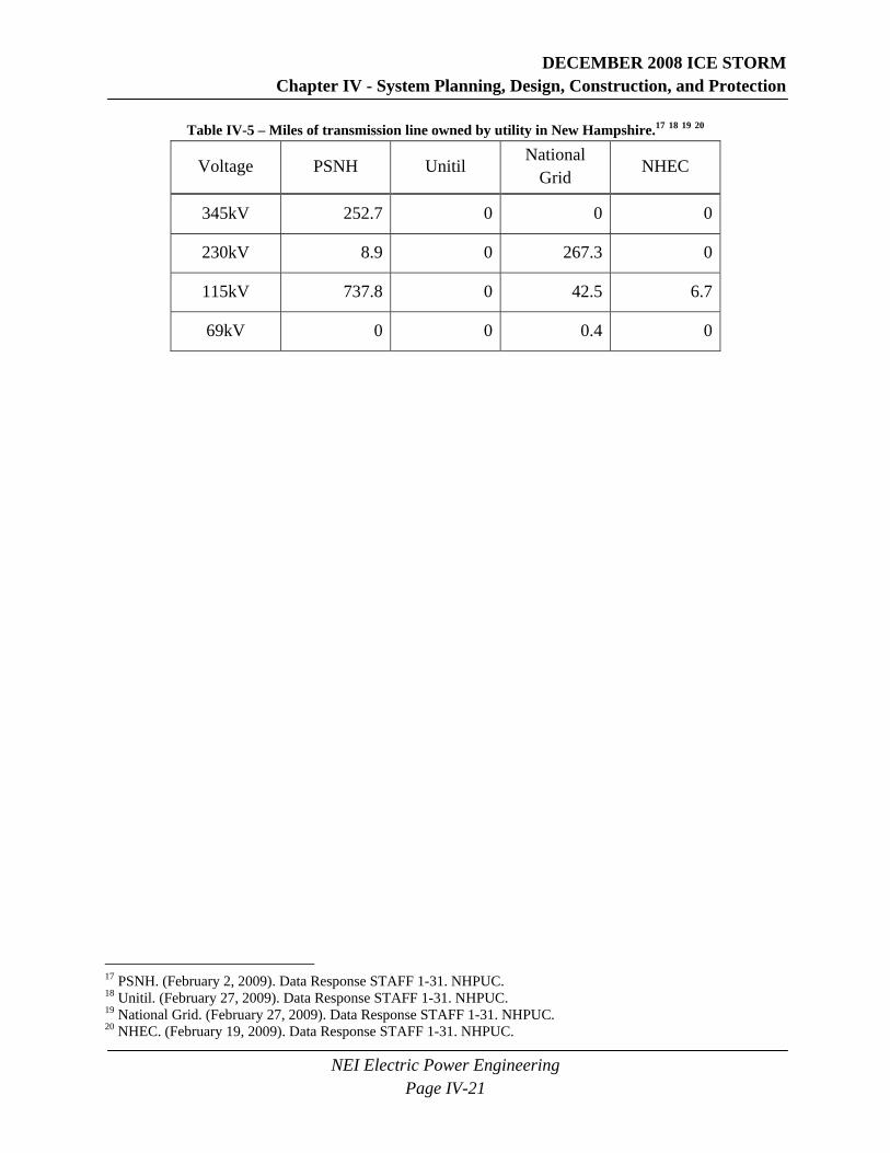
Table IV-5 – Miles of transmission line owned by utility in New Hampshire.17 18 19 20
Voltage PSNH Unitil National
Grid NHEC
345kV 252.7 0 0 0
230kV 8.9 0 267.3 0
115kV 737.8 0 42.5 6.7
69kV 0 0 0.4 0
17 PSNH. (February 2, 2009). Data Response STAFF 1-31. NHPUC. 18 Unitil. (February 27, 2009). Data Response STAFF 1-31. NHPUC. 19 National Grid. (February 27, 2009). Data Response STAFF 1-31. NHPUC. 20 NHEC. (February 19, 2009). Data Response STAFF 1-31. NHPUC.

DECEMBER 2008 ICE STORM Chapter IV - System Planning, Design, Construction, and Protection
NEI Electric Power Engineering Page IV-22
The following is a summary of each utility’s transmission line outages including a map in Figure IV-8 that shows the locations of the transmission lines which tripped off during the storm.
Figure IV-8 – Transmission line outages due to the December 2008 ice storm.
DECEMBER 2008 ICE STORM Chapter IV - System Planning, Design, Construction, and Protection
NEI Electric Power Engineering Page IV-23
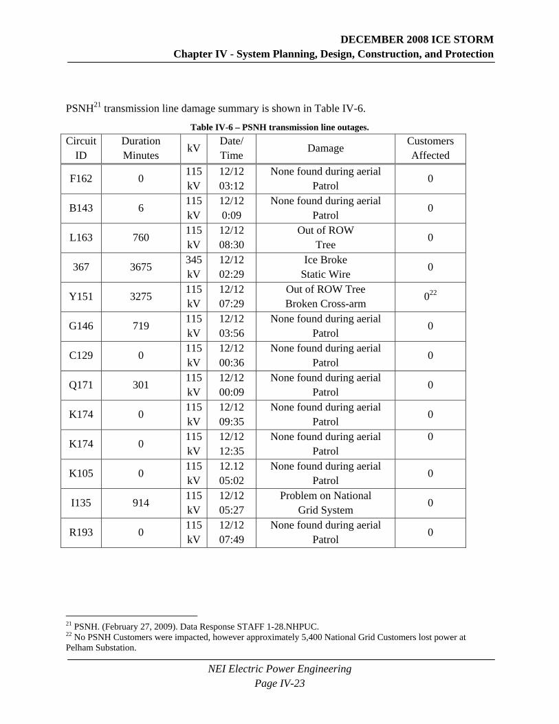
PSNH21 transmission line damage summary is shown in Table IV-6.
Table IV-6 – PSNH transmission line outages. Circuit
ID Duration Minutes
kV Date/ Time
Damage Customers Affected
F162 0 115 kV
12/12 03:12
None found during aerial Patrol
0
B143 6 115 kV
12/12 0:09
None found during aerial Patrol
0
L163 760 115 kV
12/12 08:30
Out of ROW Tree
0
367 3675 345 kV
12/12 02:29
Ice Broke Static Wire
0
Y151 3275 115 kV
12/12 07:29
Out of ROW Tree Broken Cross-arm
022
G146 719 115 kV
12/12 03:56
None found during aerial Patrol
0
C129 0 115 kV
12/12 00:36
None found during aerial Patrol
0
Q171 301 115 kV
12/12 00:09
None found during aerial Patrol
0
K174 0 115 kV
12/12 09:35
None found during aerial Patrol
0
K174 0 115 kV
12/12 12:35
None found during aerial Patrol
0
K105 0 115 kV
12.12 05:02
None found during aerial Patrol
0
I135 914 115 kV
12/12 05:27
Problem on National Grid System
0
R193 0 115 kV
12/12 07:49
None found during aerial Patrol
0
21 PSNH. (February 27, 2009). Data Response STAFF 1-28.NHPUC. 22 No PSNH Customers were impacted, however approximately 5,400 National Grid Customers lost power at Pelham Substation.
DECEMBER 2008 ICE STORM Chapter IV - System Planning, Design, Construction, and Protection
NEI Electric Power Engineering Page IV-24
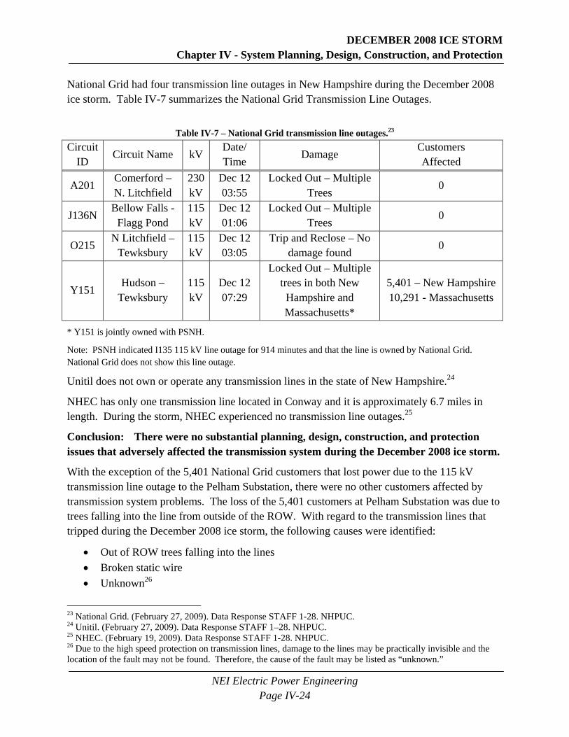
National Grid had four transmission line outages in New Hampshire during the December 2008 ice storm. Table IV-7 summarizes the National Grid Transmission Line Outages.
Table IV-7 – National Grid transmission line outages.23 Circuit
ID Circuit Name kV
Date/ Time
Damage Customers Affected
A201 Comerford – N. Litchfield
230 kV
Dec 12 03:55
Locked Out – Multiple Trees
0
J136N Bellow Falls -
Flagg Pond 115 kV
Dec 12 01:06
Locked Out – Multiple Trees
0
O215 N Litchfield –
Tewksbury 115 kV
Dec 12 03:05
Trip and Reclose – No damage found
0
Y151 Hudson –
Tewksbury 115 kV
Dec 12 07:29
Locked Out – Multiple trees in both New Hampshire and Massachusetts*
5,401 – New Hampshire 10,291 - Massachusetts
* Y151 is jointly owned with PSNH.
Note: PSNH indicated I135 115 kV line outage for 914 minutes and that the line is owned by National Grid. National Grid does not show this line outage.
Unitil does not own or operate any transmission lines in the state of New Hampshire.24
NHEC has only one transmission line located in Conway and it is approximately 6.7 miles in length. During the storm, NHEC experienced no transmission line outages.25
Conclusion: There were no substantial planning, design, construction, and protection issues that adversely affected the transmission system during the December 2008 ice storm.
With the exception of the 5,401 National Grid customers that lost power due to the 115 kV transmission line outage to the Pelham Substation, there were no other customers affected by transmission system problems. The loss of the 5,401 customers at Pelham Substation was due to trees falling into the line from outside of the ROW. With regard to the transmission lines that tripped during the December 2008 ice storm, the following causes were identified:
• Out of ROW trees falling into the lines • Broken static wire • Unknown26
23 National Grid. (February 27, 2009). Data Response STAFF 1-28. NHPUC. 24 Unitil. (February 27, 2009). Data Response STAFF 1–28. NHPUC. 25 NHEC. (February 19, 2009). Data Response STAFF 1-28. NHPUC. 26 Due to the high speed protection on transmission lines, damage to the lines may be practically invisible and the location of the fault may not be found. Therefore, the cause of the fault may be listed as “unknown.”
DECEMBER 2008 ICE STORM Chapter IV - System Planning, Design, Construction, and Protection
NEI Electric Power Engineering Page IV-25
The PSNH broken static line was probably one of the more severe problems on the transmission system since it affected a 345 kV line that was out of service for over 61 hours. A review of that incident revealed that an ice laden static wire27 came into contact with energized phase conductors.
Figure IV-9 shows the conditions after the static line failure. As can be seen in the bottom right side of the picture, the static wire which is normally on the top of the right leg of the two-pole wood H-Frame 345 kV structure is now lying on the ground. The static wire attached to the top of the left leg is still in place but sagging extremely low and appears to be near one of the 345 kV phase conductors. While this could be somewhat of an optical illusion, a small wind could blow the static wire into the phase conductor. Evidence that wind accompanied the formation of the ice on the line is shown in Figure IV-10 where it may be seen that the icicles attached to the conductor are not vertical.
The causes for ten of the recorded line faults (see Table IV-7 and Table IV-6) were never determined. These resulted in short outages or successful recloses of transmission line breakers and were likely caused by either ice induced galloping or line jumping. Ice induced galloping is defined as “low-frequency, high-amplitude, wind-induced vibration associated with the effect of ice, glaze or rime deposits on the aerodynamic characteristics of conductors”.28 Line jumping is caused by ice shedding, which occurs when ice formed on conductors or overhead ground wires suddenly drops off causing the conductor to jump.29 Either galloping or line jumping may cause phase conductors to move sufficiently so as to come into close proximity, or even direct contact, with other conductors. If two conductors come close enough to each other, an electric arc may occur between them. Even worse, the two conductors may touch each other. Either condition will cause a momentary fault. In the cases where the ice storm did have an impact on the transmission system, the system protection worked effectively to isolate faulted lines and restore the supply of power quickly through reclosing when possible.
27 Static wire is a non-current carrying conductor located above the current carrying phase conductors and is commonly used to shield the phase conductors from lightning. 28 Electric Power Research Institute, (n.d.) Transmission Line Reference Book, Wind-induced Conductor Motion, pg.114. 29 Fekr, M.R. (October 1995). Dynamic Response of Overhead Transmission Lines to Ice Shedding, pg. 2.

DECEMBER 2008 ICE STORM Chapter IV - System Planning, Design, Construction, and Protection
NEI Electric Power Engineering Page IV-26
Figure IV-9 - PSNH 345kV line 367 - Static Wire Failure. (Photo courtesy of PSNH)
Figure IV-10 - Close-up of ice shown in Figure IV-9. (Photo courtesy of PSNH)
Non-Broken Static Wire
Downed Broken Static Wire
DECEMBER 2008 ICE STORM Chapter IV - System Planning, Design, Construction, and Protection
NEI Electric Power Engineering Page IV-27
Recommendation No. 1: PSNH should inspect the condition of the static wire on Line 367, compare it with the original design, and present a report to the NHPUC.
• PSNH should determine if the 7 No. 10 Alumoweld static wire was damaged during the December 2008 ice storm.
• PSNH should determine if a similar failure during a similar icing condition is likely in the future.
• PSNH should determine if any upgrades or static wire replacements are needed as a result of the December 2008 ice storm.
• PSNH should determine and document the life expectancy of the remaining static wires on its system.
• PSNH should plan for upgrading static wires which may be reaching the end of their life and consider replacing existing wires with fiber optic overhead ground.
Conclusion: NHEC had limited back-up power for substation SCADA during the December 2008 ice storm.
The installed uninterruptable power supplies (UPS) for SCADA provided back-up power for only approximately 1-1/2 hours at each substation.30 31 Since the duration of the power outages exceeded this time period, the batteries for the UPS discharged and SCADA was not available. A better practice, and one recommended by industry standards, is to have eight hours of backup power.
Recommendation No. 2: NHEC should upgrade their substation SCADA back-up power systems to provide reliable power for a minimum of eight hours.
• NHEC should size their battery systems for a minimum of 8 hours of backup power as recommended in RUS Bulletin 1724E-300 – Design Guide for Rural Substations.
Conclusion: The replacement of the existing overhead transmission system in New Hampshire with an underground transmission system is impractical and unwarranted.
With very few exceptions, transmission lines and transmission substations are constructed above ground. Exceptions are typically in urban areas where land is not readily available to construct overhead transmission lines and substations. In addition, construction costs for underground transmission systems are quite high and design constraints are considerable. These include requiring shorter lines at higher voltages, developing methods to handle extreme line charging current due to capacitance, voltage regulation becomes more difficult, and repair times will be unacceptably long. (See Appendix B for a detailed discussion.) In New Hampshire, given the state’s mountainous and rural topography, the most practical means of constructing a transmission system is overhead.
30 Hutchison, J. Manager Engineering Support Services, NHEC. Interview by Ackerman, A. June 8, 2009. 31 Lynch, H. Disaster Recovery Executive, NHEC. Interview by Ackerman, A. June 8, 2009.
DECEMBER 2008 ICE STORM Chapter IV - System Planning, Design, Construction, and Protection
NEI Electric Power Engineering Page IV-28
The impact of the December 2008 ice storm on the New Hampshire transmission system was minimal and resulted in only 5,401 customers losing power. Of those 5,401 customers, a large percentage of those customers would have been without power due to distribution feeder outages at Pelham Substation.32 So, neither financial nor reliability benefits would justify the placement of the overhead transmission system underground.
Conclusion: Unlike the transmission system, the sub-transmission lines were adversely impacted by the December 2008 ice storm, resulting in the loss of power to many customers. However, the adverse impact on the sub-transmission lines was from ice laden trees and tree limbs falling into the power system, and not due to planning, design, construction, or protection issues..
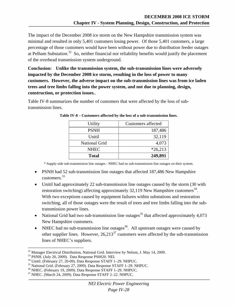
Table IV-8 summarizes the number of customers that were affected by the loss of sub-transmission lines.
Table IV-8 – Customers affected by the loss of a sub-transmission lines.
Utility Customers affected PSNH 187,486Unitil 32,119
National Grid 4,073NHEC *26,213Total 249,891
* Supply-side sub-transmission line outages - NHEC had no sub-transmission line outages on their system.
• PSNH had 52 sub-transmission line outages that affected 187,486 New Hampshire customers.33
• Unitil had approximately 22 sub-transmission line outages caused by the storm (30 with restoration switching) affecting approximately 32,119 New Hampshire customers34. With two exceptions caused by equipment failures within substations and restoration switching, all of those outages were the result of trees and tree limbs falling into the sub-transmission power lines.
• National Grid had two sub-transmission line outages35 that affected approximately 4,073 New Hampshire customers.
• NHEC had no sub-transmission line outages36. All upstream outages were caused by other supplier lines. However, 26,21337 customers were affected by the sub-transmission lines of NHEC’s suppliers.
32 Manager Electrical Distribution, National Grid. Interview by Nelson, J. May 14, 2009. 33 PSNH. (July 20, 2009). Data Response PS0020. NEI. 34 Unitil. (February 27, 20-09). Data Response STAFF 1–29. NHPUC. 35 National Grid. (February 27, 2009). Data Response STAFF 1–29. NHPUC. 36 NHEC. (February 19, 2009). Data Response STAFF 1–29. NHPUC. 37 NHEC. (March 24, 2009). Data Response STAFF 2–22. NHPUC.
DECEMBER 2008 ICE STORM Chapter IV - System Planning, Design, Construction, and Protection
NEI Electric Power Engineering Page IV-29
Conclusion: Outages to numerous sub-transmission lines during the December 2008 ice storm adversely impacted the operation of distribution substations.
Distribution substations are essential for delivering power to the customer. During the December 2008 ice storm, power on distribution lines exiting the distribution substations could not be restored until the sub-transmission lines were restored. Loss of the sub-transmission lines serving the distribution substations was the result of ice laden limbs and whole trees falling into power lines and was not due to planning, design, construction, or protection of the sub-transmission lines or substations.
Conclusion: In many locations, the sub-transmission lines have distribution loads connected to them.
In New Hampshire, most distribution loads are connected to 5 kV (2,400, 4,160 and 4,800 Volt), 15 kV (12.47, 13.2 and 13.8 kV) or 34.5kV systems. The 34.5 kV (as well as some 23 and 46 kV) voltage class is the common sub-transmission voltage level that is used to supply many distribution substations. Since the loss of a sub-transmission line can affect many customers due to the loss of one or more distribution substations, the importance of reliability on the sub-transmission system is high. Connecting customers directly to the 34.5 kV sub-transmission system adds tap splices, additional overhead lines, pole mounted transformers, and service drops—all of which are vulnerable to damage caused by weather. Adding equipment to any system increases the possibility of damage simply by having more pieces exposed. Twenty-nine PSNH sub-transmission and distribution lines were lost during the storm and affected 82,359 customers.
Recommendation No. 3: Each electric utility should perform a review of distribution loads supplied by sub-transmission lines.
• The electric utilities should include in their extended operations and construction plans a review of distribution loads supplied by sub-transmission lines.
• The electric utilities should examine reliability issues at sub-transmission supplied distribution loads with an emphasis on the effects caused by the December 2008 ice storm.
• The electric utilities should examine alternatives that would remove customers from the sub-transmission lines.
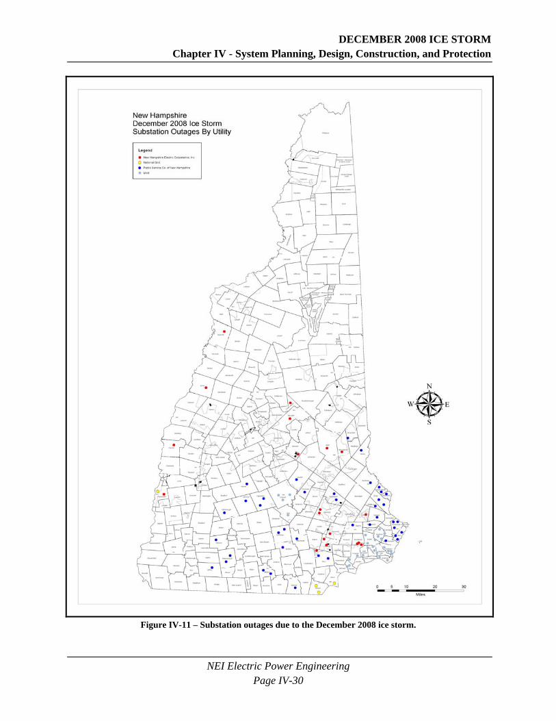
Conclusion: Approximately 100 distribution substations lost power during the December 2008 ice storm, affecting 159,549 customers. These substations are shown in Figure IV-11. Except for two minor exceptions, none of the outages appear to have been the result of inadequate planning, design, construction, or protection of the distribution substations.
DECEMBER 2008 ICE STORM Chapter IV - System Planning, Design, Construction, and Protection
NEI Electric Power Engineering Page IV-30
Figure IV-11 – Substation outages due to the December 2008 ice storm.
DECEMBER 2008 ICE STORM Chapter IV - System Planning, Design, Construction, and Protection
NEI Electric Power Engineering Page IV-31
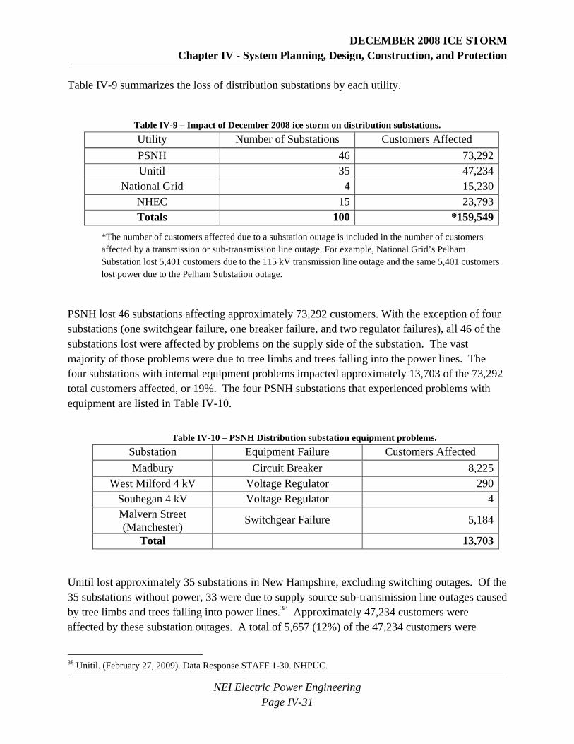
Table IV-9 summarizes the loss of distribution substations by each utility.
Table IV-9 – Impact of December 2008 ice storm on distribution substations. Utility Number of Substations Customers Affected PSNH 46 73,292Unitil 35 47,234
National Grid 4 15,230NHEC 15 23,793Totals 100 *159,549
*The number of customers affected due to a substation outage is included in the number of customers affected by a transmission or sub-transmission line outage. For example, National Grid’s Pelham Substation lost 5,401 customers due to the 115 kV transmission line outage and the same 5,401 customers lost power due to the Pelham Substation outage.
PSNH lost 46 substations affecting approximately 73,292 customers. With the exception of four substations (one switchgear failure, one breaker failure, and two regulator failures), all 46 of the substations lost were affected by problems on the supply side of the substation. The vast majority of those problems were due to tree limbs and trees falling into the power lines. The four substations with internal equipment problems impacted approximately 13,703 of the 73,292 total customers affected, or 19%. The four PSNH substations that experienced problems with equipment are listed in Table IV-10.
Table IV-10 – PSNH Distribution substation equipment problems.
Substation Equipment Failure Customers Affected Madbury Circuit Breaker 8,225
West Milford 4 kV Voltage Regulator 290Souhegan 4 kV Voltage Regulator 4Malvern Street (Manchester) Switchgear Failure 5,184
Total 13,703
Unitil lost approximately 35 substations in New Hampshire, excluding switching outages. Of the 35 substations without power, 33 were due to supply source sub-transmission line outages caused by tree limbs and trees falling into power lines.38 Approximately 47,234 customers were affected by these substation outages. A total of 5,657 (12%) of the 47,234 customers were
38 Unitil. (February 27, 2009). Data Response STAFF 1-30. NHPUC.

DECEMBER 2008 ICE STORM Chapter IV - System Planning, Design, Construction, and Protection
NEI Electric Power Engineering Page IV-32
affected due to equipment problems at two substations. Those two substations are shown in Table IV-11.
Table IV-11 – Unitil distribution substation equipment problems. Substation Equipment Failure Customers Affected
Iron Works Road Transformer Failure 2,795Westville Transformer Fuse Opened 2,962
Total 5,657
The Iron Works Road Substation transformer failure was most likely the combined result of the relatively unusual transformer winding connection, grounded-wye/delta/grounded-wye, in conjunction with an upstream single phasing condition. While there was a minimal amount of forensics that took place, the transformer appeared to have overheated. It is quite probable that an upstream 34.5 kV single phasing condition took place. Due to the nature of the transformer windings, the grounded-wye primary winding combined with the delta tertiary would result in the transformer trying to supply power to the 34.5kV side of the phase that was open. Over time, there would have been an overloading of the tertiary winding which may have led to the ultimate failure. High side fuses were used to protect the transformer and this unusual condition could not be sensed by these fuses. The transformer continued to operate in an overloaded condition until it failed. High side breaker protection and better protective relaying may have prevented this failure from occurring. There are other transformers of similar design on the system for which the transformer protection should be reviewed. Another possible solution would be to remove the ground on the primary grounded-wye winding.
Unitil has similar transformers located in other parts of its system. The southern half of Unitil’s Capital Division has five substations in which the transformers are connected primary grounded-wye to secondary grounded-wye.39 Four of those substations have transformers which have a third winding that is delta connected. Due to the delta connection of the third winding in the transformer, there is a reasonable probability that a similar system condition during a storm and similar type of failure could occur in any one of those five substations. Unitil should review this scenario and develop a solution to prevent a future similar problem.
National Grid lost four substations affecting approximately 15,230 customers. All four substations were lost due to supply side transmission or sub-transmission lines outages caused by ice laden tree limbs and trees falling into power lines.
NHEC reportedly had 27 substations affected by the December 2008 ice storm.40 However, the number of substation outages caused by primary power supply failures was 15, which affected approximately 23,793 customers.
39 Zogopoulos, A.J., Design and Standards Specialist, Unitil. Interview by Nelson, J. August 8, 2009. 40 NHEC included all impacts to substations including single phasing and loss of feeders.

DECEMBER 2008 ICE STORM Chapter IV - System Planning, Design, Construction, and Protection
NEI Electric Power Engineering Page IV-33
Recommendation No. 4: Unitil should investigate the failure of the Iron Works Substation transformer and correct any deficiencies on their system that could result in failures in the future.
• Unitil should investigate and modify if necessary the transformer protection at the Iron Works Road substation.
• Unitil should investigate and modify if necessary the transformer protection at the Bow Junction Substation.
• Unitil should investigate and modify if necessary the transformer protection at the Montgomery Street Substation.
• Unitil should investigate and modify if necessary the transformer protection at the Storrs Street Substation.
Conclusion: Damage to the underground distribution system was non-existent.
The vast majority of damage to the electrical infrastructure in New Hampshire was the result of tree limbs and trees falling into overhead power lines. The underground system was not impacted by the December 2008 ice storm.
Conclusion: Damage to the overhead distribution system was extensive, and with few exceptions, was caused by ice laden tree limbs and trees falling into power lines.
Some collateral damage was noted in a few substations where electrical equipment failed. The December 2008 ice storm was most likely a contributing factor to those failures primarily due to the stresses caused on the substation equipment by upstream and downstream faults.
Conclusion: Conversion of the entire overhead distribution system to underground is not practical, would be very expensive, and would take many, many decades to complete.
Converting the entire distribution system from overhead to underground would be highly impractical in New Hampshire. Conversion of some portions of the distribution system may be practical if the higher costs are acceptable and the following conditions exist:
• The system is an urban (not rural) distribution system with moderately dense population. • The conversion is done as part of a long term (i.e., decades long) project. • The conversion is coordinated and can share costs with other maintenance projects such
as street repair. • The conversion is done in conjunction with retiring old overhead lines. • The municipality passes ordinance making underground lines required for all new
construction and new costs are passed on to homeowners. • The utility should be able to dedicate a full time crew who will be responsible for the
conversion during the many years it would likely take.
Some benefits will be seen if the utility decides to place underground those parts of the system that can be economically converted. Following an ice storm the undamaged underground portion

DECEMBER 2008 ICE STORM Chapter IV - System Planning, Design, Construction, and Protection
NEI Electric Power Engineering Page IV-34
of the system can be ignored and resources can be diverted to concentrate on the damaged overhead system. This should speed overall system restoration. (See Appendix B for a more thorough and technical discussion on overhead to underground conversion.)
Table B-1 from Appendix B is reproduced below as Table IV-12, summarizing the data responses from the four electric utilities on the cost of converting the existing overhead distribution system (including the sub-transmission lines) to underground. The total estimated cost for the conversion, based on the data provided by the four electric utilities, is $43 billion. (See Appendix B for costs associated with overhead to underground conversions.) In addition, the amount of construction that would be required could easily take 50 years, at which time the original cable installed at the beginning of the project would need to be replaced due to reaching the end of its service life. In other words, there would be perpetual construction on the underground system. According to the data provided by the four electric utilities, the average cost per customer for the conversion would be in the range of $34,746 with National Grid at the low end to $72,563 with NHEC at the high end. Three of the four utilities’ data showed an average cost in the $70,000 range per customer. Using the lowest cost estimate per customer, the average electric customer may see a monthly increase of over $400 to their electric bill in perpetuity. There appears to be no economical benefit to placing the electric distribution system underground except in special cases where costs can be minimized, reliability improved, and the cost to benefit ratio is reasonable.
Table IV-12 – New Hampshire electric utility high level overhead to underground cost summary.
National
Grid NHEC PSNH Unitil
U/G Distribution Costs - Lines and Substations (millions)
$1,288 $3,845
$29,946 $1,664
Overhead Distribution Line Removal Costs (millions)
$55 $364 $305 $627
U/G Distribution Costs – Services to Customer (millions)
$90 $903 $3,360 $562
Total Cost (millions) $1,433 $5,112 $33,611 $2,853Number of Customers 41,156 70,422 492,000 41,264Average Cost Per Customer $34,819 $72,591 $68,315 $69,140Average monthly electric bill increase*
$434/mo $907/mo $854/mo $864/mo
*Average Monthly Electric Bill = Average Capital Investment x (FCR)/ 12 months where FCR is the fixed charge rate or annual recovery rate of a capital expenditure into perpetuity. 15% was used for FCR which includes such costs as rate of return, replacement cost, insurance and taxes.
DECEMBER 2008 ICE STORM Chapter IV - System Planning, Design, Construction, and Protection
NEI Electric Power Engineering Page IV-35
Conclusion: With few exceptions, protection devices operated correctly during the December 2008 ice storm and did not adversely affect the system. However, there are some improvements that should be made by replacing older electromechanical relays.
Due to extensive damage on the power system, a large number of protective circuit devices such as fuses, circuit breakers, reclosers, and sectionalizers operated. There was indication of only one circuit breaker failure that happened late during the power restoration. However, the protective devices acted only to isolate the faulted sections of the system and did not provide pre-fault and fault data so that the operation of the protective device could be analyzed.
State of the art protective devices and communication links are available that provide better protection and control. These devices are capable of capturing pre-fault and fault data, which is very useful for analysis of mis-operation of protective devices and forensic studies of equipment failures.
By replacing electro-mechanical relays with micro-processor based relays system reliability and security can be improved. In addition, by adding micro-processor based relays, the implementation or expansion of SCADA systems will be facilitated. This would improve storm response in the future by providing better system information on both system status and faults.
Recommendation No. 5: Each electric utility should replace existing electro-mechanical relays with microprocessor based relays that feature event reporting ability.
• The electric utilities should implement and/or complete plans to replace all their electro-mechanical relays with microprocessor based relays.
• The electric utilities should choose relays with event recording capability. • The electric utilities should incorporate the new relays into their SCADA systems.
Conclusion: Covered wire is used extensively by New Hampshire utilities and provides an advantage during normal operations41 by limiting the number of incidental tree and tree branch contacts with conductors that affect the reliability of the sub-transmission and distribution systems. However, covered wire systems should not be considered a weather hardening protection scheme.
Covered wire does not provide a distinct advantage during extreme weather disturbances due to the need to be de-energized to clear debris and make repairs that often take longer to complete than they would if bare wire was used. In addition, because the covered wire does not have an insulating shield, it is not intended for and cannot be depended upon for absolute personal protection.42
41 Normal conditions are typical days without wind, snow, rain or lightning. 42Landinger, C.C., McAulife, J.W., Clapp, A.L., Dagenhart, J.B., Thue, W.A. (April 1997). “Safety Considerations of Aerial Systems Using Insulated and Covered Wire and Cable.” IEEE Transactions on Power Delivery, Vol 12, (2), pgs. 1012-1016. (10.1109/61.584430).

DECEMBER 2008 ICE STORM Chapter IV - System Planning, Design, Construction, and Protection
NEI Electric Power Engineering Page IV-36
Conclusion: The amounts of ice reported in New Hampshire due to the 2008 storm vary greatly among sources and therefore were unreliable for calculating system line performance due to ice and wind loading.
Due to the inconsistent reporting of ice accretion, the amount of ice that accumulated during the storm is somewhat subjective. Many people may measure the size of icicles and report that as the amount of ice. The ice loading which is important to the line designer is the amount of equivalent radial ice, and this is difficult to calculate or measure. Equations have been developed by Army Corp of Engineers Cold Regions Research and Engineering Laboratory (CRREL) that equates an uneven ice measurement to an equivalent thickness of ice that will produce both the same weight load on a line and an equivalent diameter for wind to act on the line. These equations are used to determine the effective amount of radial ice that accumulated during the storm.
Conclusion: The maximum radial ice seen in New Hampshire in the December 2008 ice storm was found to be 1/2 inch. An equivalent storm with this ice thickness can be expected to occur once every ten years.
CRREL in Hanover, New Hampshire worked closely with NEI to study the effects of this storm and report, among other things, the maximum equivalent radial ice observed. It is noteworthy that CRREL is the same group that gathers the data and prepares the ice loading maps which are used by the American Society of Civil Engineers (ASCE) and other code-writing bodies. The weather data provided by CRREL is then used by engineers in the design of overhead power lines. CRREL reports that the maximum radial ice seen in New Hampshire was in the Manchester area and was 1/2 inch. According to empirical evidence cited by CRREL, an ice storm with 1/2 inch of radial ice can be expected approximately every ten years in New Hampshire.43 Only 4/10 inch of radial ice was found to have occurred in southwestern New Hampshire in the Jaffrey area. This storm was of far smaller magnitude in terms of ice accretion than the storm that occurred in 1998, even though it produced more damage. The 1998 storm damage area was farther north and had greater reported ice accretion, but occurred in a less populated area. NHEC and PSNH experienced significant damage to their system as a result of the 1998 storm.
Conclusion: The four New Hampshire utilities use NESC heavy loading as the basis for distribution and transmission structure designs; however, design standards vary among the utilities.
On its transmission system, PSNH uses NESC heavy loading along with the requirements in the Northeast Utilities Transmission Standard OTRM 060 “Extreme Wind & Ice Loading on Transmission Line Structures”, which appears to contain equal or more conservative design
43 Jones, Kathleen F. (July 2009) The December 2008 Ice Strom in New Hampshire. Cold Regions Research and Engineering Laboratory.
DECEMBER 2008 ICE STORM Chapter IV - System Planning, Design, Construction, and Protection
NEI Electric Power Engineering Page IV-37
standards than are contained in the NESC. All transmission lines are built to Grade B construction and all distribution is built to grade B or C as required by the NESC. On the distribution system design, PSNH uses only NESC heavy loading.
Unitil builds all of its system to Grade B or C construction standards, as required by the NESC. Where poles are jointly owned by electric and telecommunications utilities, they are designed jointly and the above conditions are applied.44 45 46 47 This is true of poles jointly used by all of the electric utilities.
National Grid uses NESC heavy loading and extreme wind standards (on structures only) for all design. For structures above 60 feet, National Grid applies extreme wind standards (on both structures and conductors) and extreme ice with concurrent wind standards, as required by the NESC. The company’s transmission system is designed with Grade B construction; distribution lines are designed to either Grade B or C standards, as required by the NESC.
NHEC uses NESC heavy loading standards for all construction, and extreme wind and extreme ice with concurrent wind standards for structures above 60 feet. NHEC builds all 34.5kV and above lines to Grade B standards and everything below 34.5kV to either Grade B or C standards, as required by the NESC.
Conclusion: The structural design for both the transmission and distribution systems were designed to sustain the loading imposed by this storm.
As noted, the maximum equivalent radial ice seen in New Hampshire was 1/2 inch, which is equal to NESC heavy loading ice requirements for design in New Hampshire. According to the CRREL report, wind was not a significant factor during this storm. The amount of ice and wind seen was far below the required 50-year return design criteria for ice with concurrent wind, which is 3/4 to 1 inch of ice with a 40 mile per hour wind. The loading conditions seen by the structures during the December 2008 ice storm were within the design criteria, and the system should have been able to sustain the amount of ice and wind which was seen without sustaining significant damage. The extreme amount of damage seen cannot be attributed to faulty or insufficient line design or construction practices. The design practices used by all the utilities in New Hampshire were the same or similar to those commonly used by utilities across the United States and the system was adequately designed for this storm.
44 Unitil. (July 10, 2009). Data Response GN0013. NEI. 45 National Grid. (July 2, 2009). Data Response GN0013. NEI. 46 PSNH. (July 10, 2009). Data Response GN0013. NEI. 47 NHEC. (July 2, 2009). Data Response GN0013. NEI.