SYSTEM OPERATION - Sayfa · Rope protectors are required wherever rope lines pass over an edge....
26
PROPRIETARY ROPE ACCESS ANCHOR POINT SYSTEMS FOR FACADE & WINDOW ACCESS SYSTEM OPERATION MANUAL SYSTEM CONTENTS In-Action 2 Features 3 Operation 4 Limitations 5 Safe Use Procedure 6 &RQ½JXUDWLRQV 14 Maintenance 16 Australian Standards 20 Technical 21 Warranty 24 6SHFL½FDWLRQV 25 1300 301 755 SAYFA.COM.AU MUST BE READ AND UNDERSTOOD PRIOR TO INSTALLATION ROPE ACCESS ANCHOR
Transcript of SYSTEM OPERATION - Sayfa · Rope protectors are required wherever rope lines pass over an edge....

PROPRIETARY ROPE ACCESS ANCHOR POINT SYSTEMS FOR FACADE & WINDOW ACCESS
SYST
EM O
PERA
TIO
N
MAN
UAL
SYSTEM CONTENTS
In-Action 2
Features 3
Operation 4
Limitations 5
Safe Use Procedure 6
14
Maintenance 16
Australian Standards 20
Technical 21
Warranty 24
25
1300 301 755 SAYFA.COM.AU
MUST BE READ AND UNDERSTOOD PRIOR TO INSTALLATION
ROPE ACCESS ANCHOR

XPLORA®
ROPE ACCESS ANCHORS
5
9
7
3
8
10
2
4
1
12
6
IT’S THE SAYFA WAY
# DESCRIPTION
1 3 SIXTY Fall arrest anchors
2 TRAVEL 8
3 SENTRY
4 ON-TRAK
5 PROTEX
6 RAPTOR Overhead fall arrest rails
For more information, please contact Sayfa Group directly.
# DESCRIPTION
7 KATT Modular fixed ladders
8 VISTA
9 ALTO
10 ALTO Stairs & platforms
12 SKYDORE Roof access hatches
3
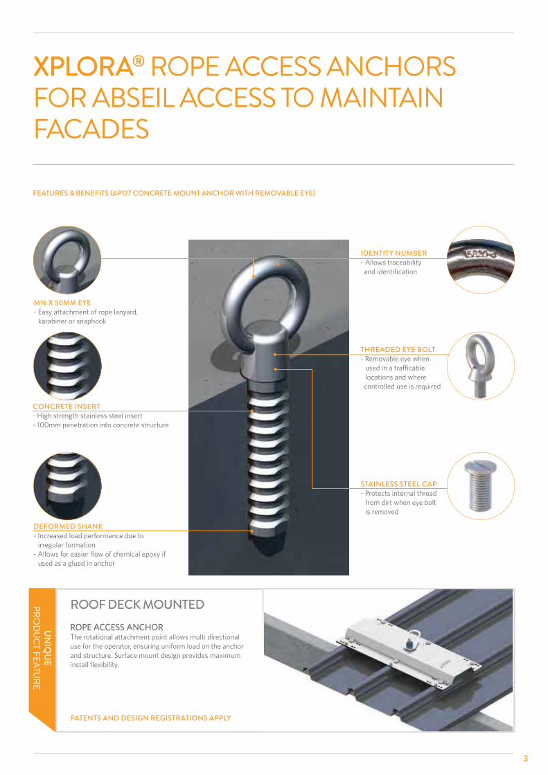
XPLORA® ROPE ACCESS ANCHORS FOR ABSEIL ACCESS TO MAINTAIN FACADES
FEATURES & BENEFITS (AP127 CONCRETE MOUNT ANCHOR WITH REMOVABLE EYE)
M16 X 50MM EYE- Easy attachment of rope lanyard, karabiner or snaphook
CONCRETE INSERT- High strength stainless steel insert - 100mm penetration into concrete structure
DEFORMED SHANK- Increased load performance due to irregular formation
used as a glued in anchor
ROOF DECK MOUNTEDROPE ACCESS ANCHORThe rotational attachment point allows multi directional use for the operator, ensuring uniform load on the anchor
UN
IQU
EPRO
DU
CT FEATURE
PATENTS AND DESIGN REGISTRATIONS APPLY
IDENTITY NUMBER- Allows traceability
THREADED EYE BOLT- Removable eye when
locations and where controlled use is required
STAINLESS STEEL CAP- Protects internal thread from dirt when eye bolt is removed

OPERATION
MUST BE READ PRIOR TO USE
Prior to use, ensure all operating procedures have been read and understood.
This rope access system is only to be used by competent persons
associated equipment.
assessment with a safe work method procedure must be completed and approved by management prior to work commencing.
This system requires periodic inspection and maintenance by a
service date is overdue.
A rescue plan must be devised and be ready to be implemented prior to usage of a rope access system.
Authorisation to enter any risk area must be obtained from the workplace manager prior to accessing.
Visually inspect the system for damage prior to use. System must not be used if there is any deterioration or deformation of any components or structure to which the system is attached.
If the rope access system is damaged or has arrested a fall, discontinue
height safety equipment inspector.
tightening, adjustment or replacement of components must be carried out by a competent height safety inspector.
Rope protectors are required wherever rope lines pass over an edge.
Where rope lines will potentially damage an edge, then an edge protection device will be required to spread rope access loads during operation.
Persons must not be allowed to work alone during rope access
All applicable Australian Standards, WHS Acts & Regulations, and Codes of Practice & Guidelines must be read and obeyed when using this safety system.
This operation manual does not in any way, replace the need for completion of a recognised rope access training course by a Registered
Failure to follow all warnings, usage and maintenance instructions may result in serious injury or death.
4

5
MUST BE READ PRIOR TO USE
rope access systems.
or hazardous environments and must be approved by the manufacturer for use in these applications.
Each Xplora rope access
Two attachment points are required per person, one for the working line and the other for the safety line.
karabiners and abseil rope lines.
The system must be set up so that the operator’s lanyard does not °
Do not tamper with system components.
This system is not to be used for tethering or lifting machinery or equipment.
height safety inspector as recommended:
LIMITATIONS
Sayfa recommends that persons using rope access systems do not work alone in case of an emergency and help is required.
competent rope access inspector.

SAFE USE PROCEDURE
6
STEP 1
Ensure system (harness and anchor) serviceability dates are current.
STEP 4
karabiners.
Ensure working line and safety line are attached to separate connection points.
STEP 3
for rope access.
Ensure anchor points are rated to rope access loads and serviceability dates are current.
STEP 2
Barricade area work zone, to ensure access by unauthorised persons is prohibited.

7
SAFE USE PROCEDURE
STEP 5
Check all attachment hardware and ropes.
Rope access must always be done by two operators.
manager and removed or tagged out of service until
STEP 8
edge. See page 13 for protection devices.
STEP 6
STEP 7
Connect descender device to working line.
Ensure all attachment hardware is correctly and securely

SAFE USE PROCEDURE
8
STEP 11
Remove foot strap rope grab device from safety line and attach to tool loop on harness.
STEP 10
Step into foot strap and climb over edge.
Operator must ensure the descender and backup device have been positioned correctly with no slack rope line between attachment point and operator.
STEP 9
Attach foot strap with rope grab device to safety line.
STEP 12
Descend on rope lines to carry out work to be done on facade.
Suitable facade protection maybe required to protect against damage.

9
SAFE USE PROCEDURE
STEP 2
Locate ladder beside rope lines.
Ensure hooks locate securely over parapet and base is secure.
STEP 1
Retrieve portable ladder.
ACCESS OVER HIGH PARAPET
STEP 3 STEP 4
Climb ladder.

SAFE USE PROCEDURE
10
STEP 6
Connect descender device to working line.
STEP 5
Straddle parapet.
Ensure all rope line attachment hardware is correctly and
ACCESS OVER HIGH PARAPET
11
SAFE USE PROCEDURE
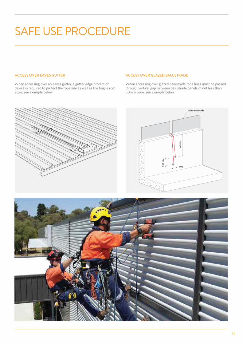
ACCESS OVER EAVES GUTTER
When accessing over an eaves gutter, a gutter edge protection device is required to protect the rope line as well as the fragile roof
ACCESS OVER GLAZED BALUSTRADE
When accessing over glazed balustrade rope lines must be passed through vertical gap between balustrade panels of not less than

TYPICAL ROPE ACCESS SET-UP USING A DIVERSION SYSTEM
- Diversion lanyard to be attached to working and safety line using approved rope access procedures.
12
SAFE USE PROCEDURE
ATTACHMENT OF ABSEIL ROPE LINES TO XPLORA ANCHOR POINTS
-
- Working line and safety line must be connected to separate anchors.
- Rope protection device must be used where the edge could damage the rope line when in use.
MULTIPLE ROPE ACCESS OPERATORS
- It is important that each set of anchors is used by one person only unless the anchorage device clearly states otherwise and has been designed for multiple operators.
1 PERSON USE PER 2 ANCHORS
1 PERSON USE PER 2 ANCHORS
BUILD
ING
EDG
E BU
ILDIN
G ED
GE
BUILD
ING
EDG
E

13
SAFE USE PROCEDURE
EXAMPLES OF ROPE EDGE PROTECTION DEVICES
14
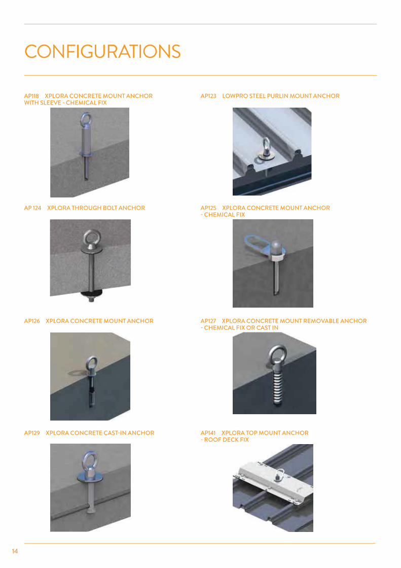
CONFIGURATIONS
AP118 XPLORA CONCRETE MOUNT ANCHOR WITH SLEEVE - CHEMICAL FIX
AP123 LOWPRO STEEL PURLIN MOUNT ANCHOR
AP 124 XPLORA THROUGH BOLT ANCHOR AP125 XPLORA CONCRETE MOUNT ANCHOR - CHEMICAL FIX
AP126 XPLORA CONCRETE MOUNT ANCHOR AP127 XPLORA CONCRETE MOUNT REMOVABLE ANCHOR - CHEMICAL FIX OR CAST IN
AP129 XPLORA CONCRETE CAST-IN ANCHOR AP141 XPLORA TOP MOUNT ANCHOR - ROOF DECK FIX

15
CONFIGURATIONS
ANCHOR MOUNTING OPTIONS
NOTES- Anchor must be 12kN rated- 2 x anchors required per rope access operator
- Used for re-belay applications
to be cast-in or through bolted when mounted overhead, loaded in tension.
NOTES- Anchor must be 12kN rated- For parapet mount application
access load.
NOTES- Anchor must be 12kN rated- For roof mount application- Lanyard not to exceed 20° causing excessive tensile load on the anchor
access load.
OVERHEAD MOUNT
SIDE MOUNT
ROOF MOUNT
20° Max

16
MAINTENANCE
by a competent rope access or height safety inspector every
the system components.
The eyelet attachment is subject to wear depending on
anchor to be replaced.
Harness gear and equipment must be maintained and stored in a dry, protected area, away from acids and ultra violet rays
Any deterioration or damage to the system or equipment must be reported to person in control of the workplace.
been completed.

17
MAINTENANCE - CONCRETE MOUNT
The checklist below outlines key checking criteria required to ensure the safe use of this system. Any item of concern not shown on the checklist must be noted on the maintenance report and brought to the attention of the workplace manager.
Items
Itemrequired corrective actions put in place. The maintenance report must clearly document all non-conforming criteria.
This system must be maintained by a competent rope access technician trained in the safe use and maintenance of this system.
SYSTEM MAINTENANCE CHECKLIST
12 - 15kNFall/Load
6 - 7.5kN 3 Mins
COMPONENT INSPECTION CRITERIA PASSED�
FAILED✖
CORRECTIVE ACTION COMPLETION DATE
- Concrete structure to be visually
-
- No evidence of anchor
- Anchor to be correctly tensioned
- Glued in anchors secure under live
-
- Data label attached and clearly
- -
COMPONENT INSPECTION CRITERIA PASSED�
FAILED✖
CORRECTIVE ACTION COMPLETION DATE
- Data label attached and clearly
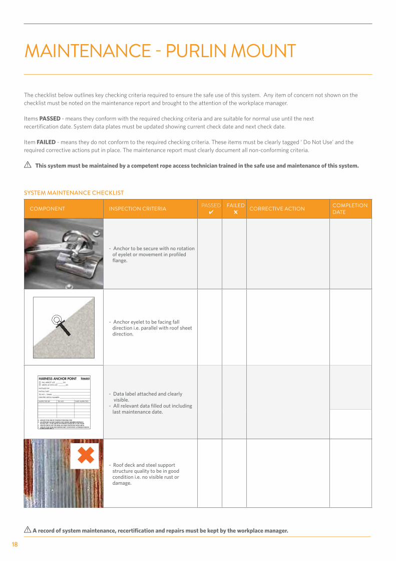
MAINTENANCE - PURLIN MOUNT
The checklist below outlines key checking criteria required to ensure the safe use of this system. Any item of concern not shown on the checklist must be noted on the maintenance report and brought to the attention of the workplace manager.
Items
Itemrequired corrective actions put in place. The maintenance report must clearly document all non-conforming criteria.
This system must be maintained by a competent rope access technician trained in the safe use and maintenance of this system.
SYSTEM MAINTENANCE CHECKLIST
HARNESS ANCHOR POINTFALL ARREST USE kNABSEIL ACCESS USE kN
INSTALLED BY:
INSTALL DATE:
TEL NO. / EMAIL:
IDENTIFICATION NUMBER:
INSPECTED BY TEL NO. DATE INSPECTED
ANCHOR TO BE USED BY COMPETENT PERSONELL ONLYAN APPROVED FULL BODY HARNESS WITH ENERGY ABSORBER CERTIFIED TO AS / NZS 1891.1 TO BE USED BY ANY PERSON CONNECTED TO THIS SYSTEMANCHOR STRICTLY NOT FOR ABSEIL USE UNLESS SPECIFICALLY NOTED ABOVEANCHOR TO BE TESTED AND CERTIFIED EVERY 12 MONTHS BY A COMPETENT PERSON AS PER AS/NZS 1891.4
ANCHOR TO BE USED BY COMPETENT PERSONELL ONLYAN APPROVED FULL BODY HARNESS WITH ENERGY ABSORBER CERTIFIED TO AS / NZS 1891.1 TO BE USED BY ANY PERSON CONNECTED TO THIS SYSTEMANCHOR STRICTLY NOT FOR ABSEIL USE UNLESS SPECIFICALLY NOTED ABOVEANCHOR TO BE TESTED AND CERTIFIED EVERY 12 MONTHS BY A COMPETENT PERSON AS PER AS/NZS 1891.4
18

19
The checklist below outlines key checking criteria required to ensure the safe use of this system. Any item of concern not shown on the checklist must be noted on the maintenance report and brought to the attention of the workplace manager.
Items
Itemrequired corrective actions put in place. The maintenance report must clearly document all non-conforming criteria.
This system must be maintained by a competent rope access technician trained in the safe use and maintenance of this system.
MAINTENANCE - ROOF DECK MOUNT
19
SYSTEM MAINTENANCE CHECKLIST
COMPONENT INSPECTION CRITERIA PASSED✔
FAILED✖
CORRECTIVE ACTION COMPLETION DATE
No evidence of penetration seal
1500mm Min
Over 5M
2000mm Min
Under 5M
200mm
Min
ID LABEL
12 - 15kN
200mm Min
6 - 7.5kN 3 Mins
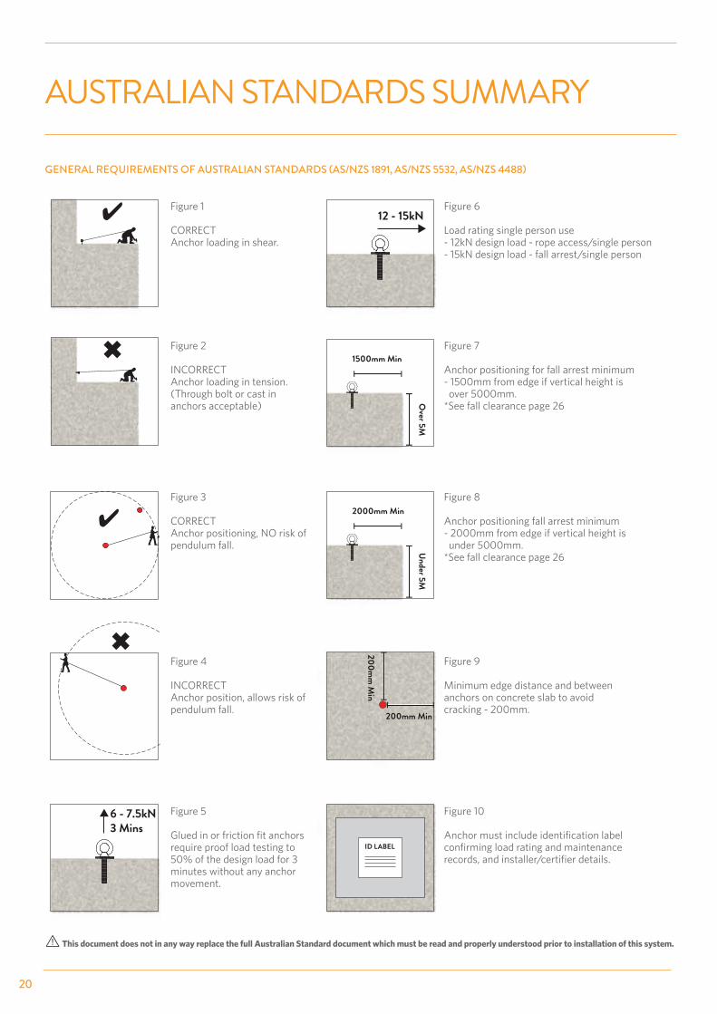
AUSTRALIAN STANDARDS SUMMARY
GENERAL REQUIREMENTS OF AUSTRALIAN STANDARDS (AS/NZS 1891, AS/NZS 5532, AS/NZS 4488)
Figure 1
Anchor loading in shear.
Figure 2
Anchor loading in tension.
Figure 3
pendulum fall.
Anchor position, allows risk of pendulum fall.
Figure 5
require proof load testing to 50% of the design load for 3 minutes without any anchor movement.
Load rating single person use
Figure 7
Anchor positioning for fall arrest minimum - 1500mm from edge if vertical height is over 5000mm.
Anchor positioning fall arrest minimum - 2000mm from edge if vertical height is under 5000mm.
Figure 9
anchors on concrete slab to avoid cracking - 200mm.
Figure 10
20
21
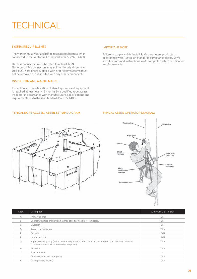
TECHNICAL
SYSTEM REQUIREMENTS
not be removed or substituted with any other component.
INSPECTION AND MAINTENANCE
TYPICAL ROPE ACCESS / ABSEIL SET-UP DIAGRAM
Code Description
A Primary anchor
B
C Diversion
D
E Deviation
F Lateral restraint
G
H Aid route
I Edge protection -
J Dead weight anchor - temporary
TYPICAL ABSEIL OPERATOR DIAGRAM
IMPORTANT NOTE
Failure to supply and/or install Sayfa proprietary products in accordance with Australian Standards compliance codes, Sayfa
and/or warranty.

TYPICAL SUNSHADE
ROPE LINE
ANCHOR IN REAR OF CONCRETE PARAPETLOAD RATED AT 12kN
ULTIMATE LOAD - 12kNLOWER FLOOR
SAFE ACCESS/FALL PROTECTION TO ANDOVER PARAPET MUST BE PROVIDED
LOAD POINTS (TO BE DESIGNED &CERTIFIED BY STRUCTURAL ENGINEER)
!
Dra
win
g N
o. 5
475
!SUN SHADE WILL NEED TO BE CONSTRUCTED AS TRAFFICABLE IF 3.0M OR LESS BELOW TOP OF PARAPET
ANCHOR POINTLOAD RATED AT 12KN
20ºMAX*
1.0M MAX(600mm PREFERRED)
TECHNICAL
ROPE ACCESS SYSTEM DESIGN LIMITATIONS
Design and installation of rope access systems must be in accordance
Primary rope access anchors require a minimum ultimate design load of
Appropriate labels or markings must be clearly visible on each anchor and include the following:
- Limitations of the system
Sayfa recommends that the design layout and installation of any rope access system is done by a fully trained and competent person with a
All structural loadings/forces on parapets, awnings and sunshades or
canopy edge.
Any structural componentry required will need to designed and approved
adequate fall protection to be provided for operator to access and attach to the rope access system safely.
Adequate protection for rope lines over sharp or fragile edges must be provided in accordance with current industry codes of practice and guidelines.
All products/systems to comply with relevant Australian Standards,
22
23
NOTES
REF: COMMENTS:

24
WARRANTY
NEVER HAS SAFETY IN THE WORKPLACE HAD A HIGHER PRIORITY
WARRANTY PERIOD ON THIS SYSTEM - 10 YEARS FROM DATE OF PURCHASE
Should you have a warranty claim as a result of a defect the following procedure must be followed:
Identify the following information:
- The product/system name and code number.
- The date of purchase/installation.
- Installation company details.
-
- The name of the company using this system.
- A description of the defect/warranty claim.
- The periodic system maintenance report.
Forward the above information to [email protected] or contact technical helpline, 1300 301 755.
TERMS & CONDITIONS
-the appearance of the defect.
- Incorrect installation or work done by a non accredited Sayfa system installer will void all warranty rights.
- Systems that have been installed using non proprietary equipment will void all warranties.
- System roof/cladding penetration seals are not covered in this warranty.
- Systems/components that have not been maintained in accordance with manufacturer’s/legislative requirements will void warranty.
- Systems used by incompetent persons or use with non compatible accessories ie. harness gear, lanyards, travellers, fall arrestors etc. will void warranty.
- Systems/components used for purposes other than their intended use will void warranty.
-frequency of use and is not covered by warranty.
DISCLAIMER
safe use and maintenance of fall arrest systems and equipment or approved by a structural engineer to ensure conformance.

2525
SYST
EM O
PERA
TIO
N
MAN
UAL
25
TECHNICAL SPECIFICATION
SYSTEM CODE DESCRIPTION
XPLORA AP118, AP123, AP124, AP125, AP126, AP127, AP129, AP141ANCHOR POINT SYSTEM FOR USE WITH HARNESS AND ROPE LANYARD
TECHNICAL DATA
COMPLIANCE
Guidelines.
TESTING Testing and performance based on requirements of Australian Standards
PRODUCT WARRANTY 10 years from date of purchase subject to correct installation, use and
recommendations.
INSPECTION AND MAINTENANCE
IMPORTANT NOTE Failure to supply and/or install proprietary product in accordance with above
Designed and manufactured by Sayfa Group. For all technical assistance contact Sayfa Group. SAYFAGROUP-08.6.2016
XPLORA ANCHOR TYPE
AP118 AP123 AP124 AP125 AP126 AP127 AP129 AP141
MATERIALS316
Stainless Steel
316 Stainless
Steel
316 Stainless Steel/EPDM
Seal
316 Stainless
Steel
316 Stainless Steel/EPDM
Seal
316 Stainless
Steel
316 Stainless
Steel
304 Stainless
Steel
RATING - ROPE ACCESS
RATING - FALL ARREST
MINIMUM CONCRETE THICKNESS
150mmMin purlin size - 150 x 150mm 150mm 180mm 150mm 150mm
Min purlin size - 150 x
MINIMUM CONCRETE STRENGTH
32MPa N/A 32MPa 32MPa 32MPa 32MPa 32MPa N/A
RECOMMENDED HOLE SIZE
18mm x 100mm
N/A 18mm18mm x 110mm
18mm x 125mm
28mm x 105mm
N/A N/A
RECOMMENDED EPOXY ADHESIVE
HILTI HITRE-500
N/A N/AHILTI HITRE-500
N/AHILTI HITRE-500
N/A N/A
MINIMUM DISTANCE TO EDGE OF STRUCTURE
200mm N/A 200mm 200mm 200mm 200mm 200mm N/A

T 1300 301 755F 1300 881 092E [email protected]
FOR MORE INFORMATION VISIT SAYFA.COM.AU
1029 MOUNTAIN HWYBORONIA VIC 3155AUSTRALIAGROUP
ACCESS PROTECT EQUIP
PRODUCT IS OWNED BY THE SAYFA GROUP. THE SAYFA GROUP CONSISTS OF:
THE SAYFA GROUP WE SAVE LIVES! This is our Mission, and it drives our Vision to BRING EVERY WORKER HOME SAFELY.
Sayfa Group leads the industry in the design, installation and management of access, fall protection and ground safety systems. As an Australian owned company, we engineer and rigorously test our proprietary systems to exceed national and international standards. Simple installation and easy to use systems are our key drivers for ensuring maximum effectiveness, improved safety and compliance with Occupational Health and Safety standards in the workplace.
OUR VALUESWe are governed by the following principles in everything we do:
A – Accountability / Totally responsible and answerable for our actions.
L – Loyalty / Steadfast and dependable based on our values in our dealings with one another.
I – Integrity / Honest and sincere, we do what we say, on time every time.
V – Value Driven / Increase what’s of value in view of a win win plan for all.
E – Enthusiastic / Motivated and inspired to continuously perform better.
COMMITMENTWe are passionate about our work with every product a testament to our commitment of world class safety, quality and performance. Our obligation is to live up to our own high standards as well as those of our customers and stakeholders ensuring total peace of mind.