System Manual DoorCom IP DCIP 600-0 DCIP 740-0
48
System Manual DoorCom IP DCIP 600-0 DCIP 740-0
Transcript of System Manual DoorCom IP DCIP 600-0 DCIP 740-0

System ManualDoorCom IP
DCIP 600-0DCIP 740-0

2
Contents
1 System description 3
2 Safety remarks 3System requirements 3
3 StructureDCIP 600-0 4DCIP 740-0 6Terms 8
4 ComponentsCalling 10Input module, camera module 11Power supply, programming, IP video server 12Software 13System-free operation 14Siedle Multi 15
5 InstallationWiring diagrams DCIP 600-0Terminals DCIP 600-0 16LED display SIVS 600/610 17Block diagrams 18DCIP 600-... up to 4 users 20DCIP 600-... with DCA 740-... 22DCIP 600-... with TME 645-... 24DCIP 600-... with COM 611-... 26DCIP 600-... withCOM 611-... and AEM 645-... 28DCIP 600-... and DRM 611-... 30
6 InstallationWiring diagrams DCIP 740-0Terminals DCIP 740-0SIM 740-0 32Wiring diagram Siedle Multi 33
7 CommissioningDCIP 600-.../DCIP 740-... 36SIM 740-... (only Siedle Multi) 38Configuration software DCIP CO 40Multicasting 39Software client DCIP SC 42
8 Setting the speech volume, level adjustmentDCIP 600-... 44DCIP 740-... 45
9 DoorCom DCA 740-01 46
10 Factory reset 47
11 Glossary, index 47

3
DoorCom IPSiedle DoorCom IP links the Siedleworld of building communication tothe IP world. Door calls aretransformed via the DoorCom IP andtransmitted via the IP network tocertain PCs. If video cameras arefitted at the door station, the pictureof the visitor is additionallytransmitted. The DoorCom IPSoftware Client is used here as avirtual in-house telephone forcommunication to the door station.The Software Client must beinstalled on every PC in the networkwhich is intended to receive a doorcall. Assignment of door calls to theSoftware Clients takes place usingan IWA address (Interface WorkingAddress) which is entered in theDoorCom IP with the aid of theconfiguration software.
DCIP 600-0The DoorCom IP 600-... links theSiedle door loudspeaker Line-LevelTLM/LL 611-... and the cameramodule CMM/CMC 612-... to an IPnetwork (10/100/1000 Mbit) on asystem-free basis.
DCIP 740-0The DoorCom IP 740-... serves as aninterface between a Siedle Multisystem and an IP network.
Both DoorCom IP variants are ableto display the picture on the PCmonitor in conjunction with theSiedle Software Client and at thesame time hold the door call via thePC. The door call can optionally alsobe held over the telephone systemusing a telephone, while the pictureis displayed by the Software Clientand all control functions such asdoor release can also be initiated bythe software. For this, a DCA 740-01must additionally be connected tothe DoorCom IP. The video camerapicture continues to appear in theSoftware Client on the PC monitor.
Danger
Mounting, installation andservicing work on electricaldevices may only be performedby a suitably qualified electrician. Failure to observe this regulationcould result in the risk of seriousdamage to health or fatal injurydue to electric shocks.• When working at the device,observe the instructions for mainscut-off.• Observe the standard DIN EN60065!When establishing the electronicconnection, observe therequirements of VDE 0805 / EN60950.• An all-pole mains switch must beprovided in the building installationwith a contact openingof at least 3 mm.• Ensure that the connection pointin the building installation is fusedwith max. 16 A.• When planning, the requireddistributor space for switch panelmounted devices must be taken intoaccount. • External voltages >30 V AC/ DCmust not be injected into the in-house telephones.
Devices with 230 V connectionIn accordance with DIN VDE 0100Part 410, Section 411.1.3 ensurethat the DoorCom installation andthe mains voltage are securelyisolated. The sheathing of theconnection cable (safety extra-lowvoltage) should only be strippedback far enough to ensure thatreliable connection is possible.
For mains connection ! and network settings such asassignment of the IP address, theresponsible network administratormust be consulted.
1 System descriptionDoorCom IP
2 Safety remarksSystem requirements
Find out about the necessary safetymeasures and system requirementsbefore starting installation andcommissioning of the DoorCom IP.
System requirementsfor the configuration software • PC with Intel Pentium III from 1 GHz or comparable processor• at least 512 MB RAM• min. 25 MB hard disk memory• Serial COM interface RS232 orserial USB adapter• CD-ROM drive for installation • VGA graphic card withat least 1024 x 768 pixel• Operating system Windows2000/XP/Vista 32 Bit• Admin rights for installationAdditional memory capacity isrequired for:• Acrobat Reader 7• Microsoft Internet Explorer fromversion 6
System requirementsfor the Software Client• Operating system MicrosoftWindows XP/Vista 32/64 BitWindows 7 32/64 Bit • Pentium IV from 2 GHz orcompatible CPUs• min. 1 GB RAM (64 Bit min. 2GB) • Graphic card with at least 1024 x 768, 128 MB and 16 bit colour depth MPEG 4 capability• 100 Mbit Ethernet card• Sound card• Microsoft DirectX 9.0c or newer• Microsoft Internet Explorerfrom version 6.0 for reading the help
Speech qualityThe audio quality (speechtransmission) is highly dependent onthe quality of the audio componentsbuilt into the PC (headset, handsetand sound card).

4
3 Structure DCIP 600-0System-free
DCIP 600-...System-free linkThe DoorCom IP 600-... serves as aninterface between a system-freeSiedle door station and an IPnetwork. In conjunction with theDoorCom IP Software Client, whichserves as a virtual in-housetelephone, the door call (incl. video)can be held via the PC. The door callcan optionally also be held via thetelephone system with a telephone.For this purpose, an additionalDCA 740-01 must be installed. Link-up of the DCA 740-01 takes placevia a free a/b port of the telephonesystem. The video camera imagecontinues to appear on the PCmonitor, control functions such asthe door release can still be operatedvia the Software Client.
The DCIP 600-... comprises thecomponents:• SIVS 600-.., system interface videoserver. Processing and adjustment ofdata, through connection of audioand video signals.• IPVS 600- .., IP video server.Processing and adjustment of audio
and video, transmission of data,audio and video to the IP network.One DCIP 600-... each is requiredper door. A maximum of 49different call destinations can bedialled. Dialling is possible by meansof a call button module, code lockmodule or display call module.• Configuration softwareDCIP CO 600-... for configuration ofthe SIVS 600-...• Software Client DCIP SC 600-... forinstallation on PC users intended toreceive door calls.
Power supplyThe DCIP 600-... SET works with 24–28 V supply voltage. An optionally connected DCA 740-01 is supplied from theSIVS 600-... . The a/b public networkinterface is supplied from the TCsystem. It is not possible to connectan individual public networktelephone directly to the a/b line ofthe DCA 740-01. The DCIP 600-... orthe IPVS 600-... is linked using astandard network cable with RJ45plug to the IP network (10/100).
Functions of the Software Client• Door calls and signalling on the PC • Text display of which door iscalling. • Door release actuation by meansof a mouse click• Light actuation by means of amouse click• Muting of the ring tone by meansof a mouse click• Selective connection to a doorstation• Parallel door call to up to 10 PCclients simultaneously• Speech connection via PC (e.g. headset) or optionally via thetelephone of a telephone system.• Almost any optional number ofdoors can be connected
Commissioning andprogrammingAfter connection of the supplyvoltage, the SIVS 600-... can beprogrammed serially with the aid ofa PRI 602-... and configurationsoftware DCIP CO 600-... via the PC.No additional programming isrequired for the optional DCA 740-01. For programming /
Siedle area IP area

5
configuration of the TC system, seethe relevant product informationand programming instructions of theTC manufacturer.
Mounting and installationThe devices are intended for switchpanel mounting. These shouldpreferably be mounted directly onenext to the other. The maximumconductor length between thedevices must not exceed 1 metre.Actuation of the link between theSIVS 600-... and the IPVS 600-...takes place via the supplied cable.The system interface video serverSIVS 600-... processes the controlsignals from the door station for theRS232 interface and switchesthrough the audio and video signalsin the case of a connection. Theprocessed signals are transferred tothe IP video server IPVS 600-... TheIPVS 600-... transforms the data,audio and video signals andestablishes communication to theTCP/IP network. One or more PCs(up to max. 49) can be called fromthe door station within a network.The Software Client must be
installed for door communication onevery PC which is intended toreceive a door call. The sound cardand headset are required to set up acall. The door call can optionally alsobe held via a telephone system usinga telephone with DTMF capability.For this purpose, the DCA 740-01must additionally be installed at ananalog PBX extension of a telephonesystem.One DCIP 600-... each is requiredper door station. This can be used tocall a maximum of 49 differentusers.
For 4 PC users, the Software Client isincluded in the scope of delivery ofthe DCIP 600-... . Each additional PCuser requires a licence for theSoftware Client DCIP SC 600-0.
DCIP 600-... System-free link with connectionof a telephone systemPerformance features• Transmission of door callswith/without video via the IPnetwork to PC users• Optionally: Audio transmission via
telephone network (DCA 740-01) inparallel to the video signal viaEthernet • Full duplex link during door calls(no push-to-talk simplexcommunication with buttonactuation)• Control commands such as doorrelease and light possible from thePC with a mouse click• Video: MPEG-4 (ISO/IEC 14496)Codec, Audio: G.711; (300Hz -3.4KHz)• The DoorCom IP manages up to49 different PC users• Selective connection to a doorstation. (Audio and/or video) • Parallel call to up to 10 PC userspossible• Combination with code lockmodule COM 611-... or display callmodule DRM 611-... possible fordirect calls to PC users.• Using the TME 645-..., more than4 call stations can be connected.
3 Structure DCIP 600-0System-free with DCA 740-01
Siedle area IP area
TelephoneSwitchboard

6
3 Structure DCIP 740-0Siedle MultiCamera assignment mode
DCIP 740-...Siedle Multi link
The DCIP 740-... behaves in thesystem in the same way as aninternal call station and isconsequently bound by the samesystem limitations (range andnumber of users). The DCIP 740-...can be used in two operating modes(camera assignment and monitorassignment). The operating mode isset in the SIM 740-... The operatingmode depends on the arrangementand system topology.
The DCIP 740-... comprises thecomponents:• SIVS 610-.., system interface videoserver. Processing and adjustment ofdata, audio and video.• IPVS 600- .., IP video server.Transmits data, audio and video tothe IP network.• SIM 740-... system interface Multi.Interface to Siedle Multi
Camera assignment mode The SIM 740-... is assigned to adoor / camera. In this mode, the
device can be assigned up to49 different call destinations whichcorrespond to the functions of49 Multi telephones. In thisoperating mode, a DCIP 740-... isrequired for each door. Thisoperating mode is advisable insystems with a small number ofdoors and a large number of PCusers.
Monitor assignment mode: Up to a maximum of 4 calldestinations, i.e. Siedle Multi systemaddresses, can be assigned to theinterface SIM 740-...These correspond to the functions ofthe 4 Multi telephones. The calldestination can be dialled from everydoor within the Siedle Multi(max. 254). This operating mode isadvisable in systems with a largenumber of doors and a smallnumber of PC users.
Power supplyThe DCIP 740-... is supplied directlyfrom the Siedle-Multi bus. Aseparate supply is consequently notrequired. An optionally connected
DCA 740-01 is supplied from theSIVS 610-...The a/b public network interface issupplied from the TC system. It isnot possible to connect an individualpublic network telephone directly tothe a/b line of the DCA 740-01.
The DCIP 740-... or the IPVS 600-...is linked using a standard networkcable with RJ45 plug to the IPnetwork.
Functions• Door call from the Siedle Multisystem and signalling to the PC• Text display of which door orwhich Multi telephone is calling. • Door release actuation by meansof a mouse click• Light actuation by means of amouse click• Selective dialling of a connectionto a Multi door station or Multi in-house telephone.• Initiation of control and switchingfunctions via a mouse click to theMulti system• Reception of status messages fromthe Siedle Multi bus
max. 1 doorstation
Siedle area IP area
TelephoneSwitchboard

7
station. (Audio and/or video)• Parallel call possible to max. 10 PCusers • With the TLC 640-... incombination with code lock module COM 611-..., alphabetical inputmodule AEM 645-0 or display callmodule DRM 611-... direct calls arepossible from PC users.
When using the camera assignmentmode and programmed parallel call,the number of maximum possiblecall destinations is reduced to 45.
• Speech connection via PC(headset) or optionally via thetelephone.
Commissioning andprogrammingAfter connection of the supplyvoltage, the devices SIM 740-... andSIVS 610-... can be programmedwith the aid of a PRI 602 via the PC.(See commissioning chapter 7)No programming is required for theDCA 740-01. For programming andconfiguration of the TC system, seethe relevant product informationand programming instructions of themanufacturer.
Mounting and installationThe DCIP 740-... can be connectedat any optional point of the SiedleMulti system bus. The devices areintended for switch panel mounting.These should preferably be mounteddirectly one next to the other. The maximum conductor length ofthe device connection must not
exceed 1 metre. The SIM 740-... is linked to the SIVS610-... with 6 cores. Actuation ofthe link between the SIVS 610-...and the IPVS 600-... takes place viathe patch cable.
Performance features• Transmission of door callswith/without video via the Ethernetto PC users • Free combination of PC callstations and Multi Siedle terminals • Audio transmission also possiblevia the telephone network(DCA 740-01) • Full duplex calls between door callstation and Software Client• Actuation of the door release andlight possible from the PC with amouse click.• Video: MPEG-4 (ISO/IEC 14496)Codec, Audio: G.711; (300Hz -3.4KHz)• From 1 door up to 49 different PCcall users can be connected• Selective connection to a door
Monitor assignment mode
max. 254 doorstations
Coax
Coax
Coax
Siedle area IP area
TelephoneSwitchboard

8
3 Terms
Camera assignmentA Siedle Multi door station can beassigned up to 49 different PC users.This operating mode is only possiblewith DCIP 740-...
ClientPC user connected to a network.
Full duplexBoth users (PC client and doorstation) have an unrestricted speechconnection. Open duplexcommunication, i.e. as opposed tothe simplex speech mode.
GatewayGateways link two differentnetworks and create connectionsacross network boundaries. Duringthis process, both the physicaltransmission modes and alsoprotocols and addresses are adjustedaccordingly.
Half duplexTwo speaking users have one speechconnection which they can usealternately, also known as push totalk.
HTTPThe Hypertext Transfer Protocol is aprotocol used for the transmission ofdata via a network. It is used mainlyto load websites and other datafrom the Internet into a webbrowser.
HubThe term hub when used in relationto network technology describes adevice which links network nodes ina star formation. Normally, the termhub is used to denote a multiportrepeater. It is used in order to linknetwork nodes or other hubs, forexample by means of an Ethernet.
IP addressInternet Protocol addressAn IP address is a number whichpermits PCs and other devices in anIP network to be addressed. Intechnical terms, the number is a 32- or 128-bit binary number.
IPInternet Protocol The IP is a network protocol inwidespread use in computernetworks. IP forms the first layer ofthe Internet protocol family which isindependent of the transmissionmedium. This means that computerscan be grouped within a networkinto logical units known as subnetsby means of an IP address andsubnet mask.
IWAInterface Working AddressSix-digit address with which thesystem interface video serverSIVS 600-... addresses the PC users.These IWA addresses are stored inthe Software Client.
LANLocal Area NetworkLocal, cable-linked network.
Monitor assignmentUp to 254 Siedle Multi door stationscan be assigned to a maximum of 4different PC users. This operatingmode is only possible withDCIP 740-... .
MulticastingTerm to denote group/parallel callswith video image to several PC userswhich have the Software Clientinstalled. For this to be possible, theUDP and IGMP V3 protocols must beimplemented in the network.
Push to TalkIn case of a connection using thehalf-duplex mode (push to talk) abutton always has to be pushed tochange the speech direction.
RouterA router is a network device whichlinks several computer networks.Network packages of a protocolarriving at the router are analysedfor information and forwarded orrouted to the intended destinationnetwork.
RS232Designation for a serial interface, forinstance the COM interface of a PC.
RS485Interface for serial data transmissionin the half-duplex mode.Transmission to a pair of cores.
ServerA server is a program which waits tobe contacted by a client program,after which it exchanges data withthe client program. The hardware onwhich the server runs is known asthe host.
Subnet maskThe subnet mask, also known asnetwork mask, is a bit mask whichseparates an IP address into anetwork and a device or hostsection. It is used in IP networks inorder to make routing decisions.
System-freeThe DCIP 600-... is operated with asystem-free connection. This meansthat the door loudspeaker workswith line signals. No system-specificdoor loudspeaker is used, forinstance the TLM 612-...
TCPTransmission Control Protocol The TCP is a protocol whichdetermines the way in which data isexchanged between computers. Alloperating systems in moderncomputers have TCP capability anduse this protocol for data exchangewith other computers. The protocolis a reliable, connection-orientedtransport protocol used in computernetworks.It is part of the internetprotocol family, which forms thefoundation of the Internet.
UDPUser Datagram ProtocolThe UDP is a minimal connectionlessnetwork protocol which belongs tothe transport layer of the Internetprotocol family. It is the task of theUDP to assign data transmitted viathe network to the right application.

9
Vario busVarious different input and controlunits can be connected to the Variobus. It comprises 4 cores. Theinformation on the Vario bus istransmitted via the RS485 protocol.
Web browserSoftware for the display andindication of Internet pages orcorresponding configuration pages. E.g. Internet Explorer or Firefox.

10
TME 640-0Call button module extension inprotective housing with screwterminals, for connection of callbutton modules TM 612-... or callbuttons of other makes.The call button modules areconnected to the TME 640-… bymeans of a matrix installation.Dimensions: 100 x 50 x 20 mm
TME 645-… by means of a ribboncable.Dimensions: 99 x 99 mm
TM 612-1 - TM 612-4Call button modules, potential-freebuttons, 1-4 call buttons, integratedLED lighting. Connection by meansof terminal block. Power supply tothe LED lighting by means ofterminal b and c with 12 V AC/DC,current consumption 25 mA per callbutton module TM 612-...Used as call buttons 1-4 directly atthe SIVS 600-...
TME 645-0Call button module extension withinterface to the Vario bus for max.8 TME 645-... . Suitable forconnection of call button moduleBTM 650 -... A maximum of 16 buscall button modules can beconnected per TME 645-… . With anacoustic signal which sounds onbutton assignment. The call buttonmodules are connected to the
4 Components for DCIP 600-... and DCIP 740-...Call buttons
BTM 650-01 - BTM 650-04Bus call button modules for In-Homebus. 1-4 call buttons, integrated LEDlighting. Connection via ribbon cableto the TME 645-... Power supply tothe LED lighting via terminals b andc with 12 V AC/DC, currentconsumption 25 mA per bus callbutton module BTM 650-...
11
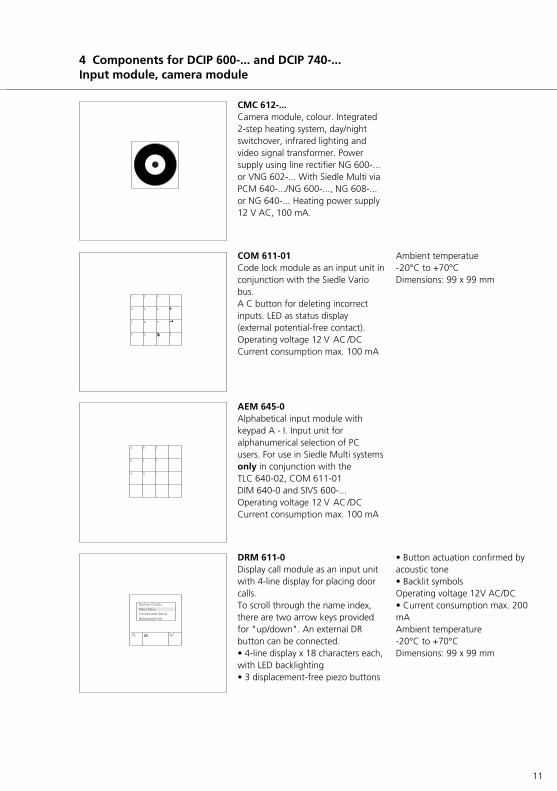
CMC 612-...Camera module, colour. Integrated2-step heating system, day/nightswitchover, infrared lighting andvideo signal transformer. Powersupply using line rectifier NG 600-...or VNG 602-... With Siedle Multi viaPCM 640-.../NG 600-..., NG 608-...or NG 640-... Heating power supply12 V AC, 100 mA.
COM 611-01Code lock module as an input unit inconjunction with the Siedle Variobus. A C button for deleting incorrectinputs. LED as status display(external potential-free contact). Operating voltage 12 V AC /DCCurrent consumption max. 100 mA
Ambient temperatue-20°C to +70°C Dimensions: 99 x 99 mm
AEM 645-0Alphabetical input module withkeypad A - I. Input unit foralphanumerical selection of PCusers. For use in Siedle Multi systemsonly in conjunction with theTLC 640-02, COM 611-01 DIM 640-0 and SIVS 600-...Operating voltage 12 V AC /DCCurrent consumption max. 100 mA
4 Components for DCIP 600-... and DCIP 740-...Input module, camera module
DRM 611-0Display call module as an input unitwith 4-line display for placing doorcalls.To scroll through the name index,there are two arrow keys providedfor "up/down". An external DRbutton can be connected. • 4-line display x 18 characters each,with LED backlighting• 3 displacement-free piezo buttons
• Button actuation confirmed byacoustic tone• Backlit symbolsOperating voltage 12V AC/DC• Current consumption max. 200mAAmbient temperature -20°C to +70°C Dimensions: 99 x 99 mm

12
4 Components for DCIP 600-... and DCIP 740-...Power supply, programming, video server
NG 600-0Line rectifier in 10-grid switch panelhousing for universal power supply.Suitable for surface mounting withZAP 10-0. Primary 230 V AC, 50 Hz,+6%-10%Secondary b/c: 14 V AC, 1 A; +/-: 24-28 V DC, 0.7 A Ambient temperature 0°C to +40°C,protection rating IP 20Dimensions: 180 x 89 x 60 mm
PRI 602-...Programming interface forconnection of a Windows PC viaserial interface to the Vario bus.Required for configuration of thesystem interface video server withsoftware DCIP CO 600-...
IPVS 600-0System interface video serverProcessing and adjustment of audioand video, transmission of data,audio and video to the IP network.Dimensions 112 x 85 x 40 mm
DCA 740-01The DoorCom Analog DCA 740-01can be connected to a universal a/binterface. In conjunction with theDCIP 600/740-... it serves as analternative speech connection if nospeech connection via PC ispreferred. Connection takes place at thestandardized a/b interface of a TCsystem (analogue PBX extension) ordirectly at the analogue telephonenetwork.Dimensions: 107 x 89 x 60 mm

13
DCIP SC 600-0DoorCom IP Software Client PCprogram, which depicts a virtualhouse telephone with video on a PCmonitor. Door calls with video are possible toone or more Siedle door stations.Execution of switching and controlfunctions such as door release, lightswitch or display of messages on thePC monitor.
DCIP CO 600-0DoorCom IP configuration softwarePC program for set-up andprogramming of the Siedle interfacevideo server SIVS 600-.../SIVS 610-...Programming takes place via theserial programming interfacePRI 602-0.
Commissioning software for theadministrator.
CD contains• DoorCom IP Software Client• DoorCom IP Configurationsoftware• DoorCom IP Manual• Siedle default configuration forIPVS 600-...• Java Runtime Environment (JRE)5.0• Microsoft Installer 3.1
For each installation of the SoftwareClient on a PC, a licence is required for the DCIP SC 600-0.
4 Device overview for DCIP 600-... and DCIP 740-...Software

14
4 Device overview only DCIP 600-...System-free operation
SIVS 600-0System interface video server forconnection of the TLM/LL 611-...Conversion of signals from the doorloudspeaker to the IPVS 600-0.Manages assignment, i.e. howwhich PC is called. Connection ofmodules COM 611-..., AEM 645-...,TME 645-... or DRM 611-... possible. Dimensions 144 x 130 x 55 mm
TLM/LL 611-0Door loudspeaker module forinterfacing at a symmetrical orasymmetrical line interface, withintegrated electret microphone andloudspeaker. Integrated echocompensation for full duplexoperation. Potential-free light buttoncapable of illumination, andcontrollable volume.
Power supply 15-28 V DCmax. 100 mALine-In 800 mVeffImpedance 2 kOhmLine-Out 100 mVeffImpedance 100 Ohm

15
4 Device overview only DCIP 740-...Siedle Multi
SIVS 610-0System interface video server, forconnection of Siedle Multi to theIPVS 600-0. The SIM 740-0 isrequired for connection. The SIVS 610-... features galvanicisolation in addition to the SIVS 600-0.Dimensions 144 x 130 x 55 mm
SIM 740-0The Multi system interface processesall Multi data protocols. Systeminformation is managed here andforwarded in neutral form to theSIVS. The SIM 740-... is able tosimulate several Multi telephones,depending on the operating mode.Only one of these “virtualtelephones“ can ever be active atone time, i.e. conduct a call.Dimensions 107 x 89 x 60 mm
VMS 641-0Video monitor switching unit, linksthe SIVS 610-... with the Multi videobus, in order to create theconnection to the correspondingdoor call station. Is required in themonitor assignment mode whenthe SIM 740-... simulates more than1 user.Dimensions: 62 x 230 x 35 mm
TLC 640-02Door loudspeaker controller in 6-gridswitch panel housing. Control unitto be used between TLM 645-... andSiedle-Multi, for two speechchannels.Dimensions: 107 x 89 x 60 mm

16
5 TerminalsDCIP 600-.../DCIP 740-...
a b c
d e f g
Terminals IPVS 600-0a No functionb Connecting socket to the ISIVS 600-.../SIVS 610-...c RJ45 socket ETH networkconnectiond Reset button to recreate the as-delivered status (after a reset, theSiedle modes must be reinstalled,see page 46.)e LED operating status lights up ingreen on readiness for operationf LED L lights up in green with anexisting network connectiong LED T flashes orange on datatransmission via the network
Terminals and LEDsh Video input 1Vss from theSIVS 600-.../SIVS 610-...i Audio-Line-In to the SIVS 600-.../SIVS 610-...j Terminal plug for control signalsk Audio-Line-Out to the SIVS 600-.../SIVS 610-...
TerminalsSIVS 600-.../SIVS 610-...a Video signal 1 Vss (cinch jack)b Terminating resistor 75 OhmON/OFFc IN = video signal 1 Vss input,D = Video signal 1 Vss throughputd Terminals for installatione Connection to IPVS 600-...gCascading to an additionalSIVS 600-.../SIVS 610-...d Terminals for installationg Grounding terminal
a
b
c
d
e
f
g
h i j k

17
4 LED displaySIVS 600-.../SIVS 610-... and IPVS 600-...
LED signalling SIVS 600-... and SIVS 610-...
Switching on
LED green LED red FunctionOFF ON After reset, power on: Device boots to operating status.ON ON The boot area is checked. Software runs in the flashFast flashing ON After a software update, the boot area is recreated.
This can take up to around 3 minutes.
Operation
LED green LED red FunctionON OFF Booting is complete. All OK. Normal status Slow flashing OFF Display, a connection existsFast flashing OFF A software update or reconfiguration process is under way
Fault
LED green LED red FunctionOFF Slow flashing ERROR, software running only in bootloader. Program memory
defective. (Device defective, possibly new software update or exchange.)
ON Slow flashing Variobus address error (error remedy possible on site)ON Fast flashing The 15 V power supply (terminal bv, cv) is overloaded. (Error
remedy possible on site)OFF OFF If supply voltage is definitely connected, the device
is defective. (Exchange)
Frequencies: Slow appr. 2 Hz, fast appr. 16 Hz
LED signalling IPVS 600-...
The underneath of the IP video server IPVS 600-... has 3 LEDs which display operating statuses and can provide anindication of possible errors.
LED operating status FunctionOFF IPVS 600-... is switched off.Lights up in green IPVS 600-... is switched onFlashes green Access to the IPVS 600-...Lights up in red (briefly) Start process runningLights up in red (continuous) Error in the device or failed upload
LED LLights up in green Network connection exists
LED TLights up in orange Active data transmission via the network

18
5 TerminalsSIVS 600-0, TLM/LL 611-0
Block diagram SIVS 600-0
G Reference for inputsE1–E4
E4 Input 4, not usedE4 Input 3, not usedE4 Input 2, not usedE4 Input 1, not usedcv- Supply voltage forbv+ Vario bus, 15 V DC,
max. 300 mADa/Db Vario bus+ Supply voltage- 24 V DCTö Door release contact
potentialTö Free max. 24 V, 1 ALi Light contactUSP Universal Switch Port bn1 Line signal to the door
station,bn2 outgoingan1 Line signal from an2 door station, incomingn1 NF signal for n2 connected
DCA 740-01
Block diagram TLM/LL 611-0
+ Terminal for - supply voltageL- Lighting, light buttonan1 Microphone signalan2Mu Muting bn1 Loudspeaker signalbn2T1 Potential-free contact T2 Light button, max, 24 V,
2 A
19
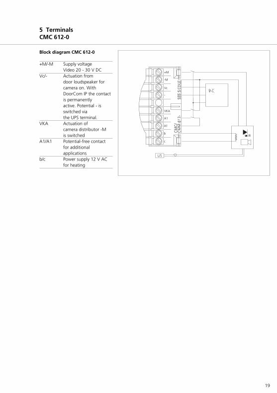
Block diagram CMC 612-0
+M/-M Supply voltageVideo 20 - 30 V DC
Vc/- Actuation from door loudspeaker for camera on. With DoorCom IP the contact is permanently active. Potential - is switched via the UPS terminal.
VKA Actuation of camera distributor -M is switched
A1/A1 Potential-free contact for additional applications
b/c Power supply 12 V AC for heating
5 TerminalsCMC 612-0

20
5 InstallationDCIP 600-... system-free up to 4 users

21
DCIP 600-... system-free up to4 users
Functional characteristicsUp to 4 PC users (Software Clients)of a network can be called from thedoor station. Calling, speech anddoor release via the Software ClientDCIP SC 600-... . The SoftwareClient must be installed on every PCwhich receives door calls. Standard call tones for the SoftwareClient 3-tone chime. A dedicated*.wav file can be assigned for eachcall tone.It is not possible to listen in to anexisting call from other PC users inthe network.The door is opened by the called PCuser using a “virtual door releasebutton”, the light switching functionis actuated using a “virtual lightbutton”. The door call can be mutedwith an optical display on themonitor.
Supplementary functions• With additional TME 645-... units,up to 49 users are possible.• Connection of the COM 611-... ispossible in order to call PC users bymeans of code selection.• Up to 10 PC users can be called inparallel with a call button from thedoor station.(Note: Every PC whichreceives a parallel door call occupies2 registrations in the IPVS 600-...)
Remarksa) Door release 12 V AC, use at least20 Ohm (e.g. TÖ 615-...)b) The NG 600-0 can also take overthe power supply to existing on-sitecall buttons. A voltage of 12 V ACmax. 200 mA is available for thelighting if a door release with animpedance of at least 20 Ohm isused. With a higher currentconsumption, an additionaltransformer must be used.• 12 V AC consumers in the wiringdiagram:• Door release appr. 600 mACamera heating appr. 100 mA• Door release contact load in theSIVS 600-... max. 24 V AC, 1 A• Light contact load in the doorloudspeaker max. 24 V AC, 2 Ac) Distance of the SIVS 600-... to thedoor station max. 200 m with J-Y(ST)Y 0.8 mm core material.Distance between the two devicesSIVS 600-... and IPVS 600-... in thedistributor max. 1 m. Duringinstallation, ensure that the doorrelease is laid in a separate cable.Power supply voltage bv+/cv- of theSIVS 600 15 V DC, max. 300 mAd) ***Optionally the DCA 740-01can be connected to the PBXextension of a telephone system.Active door calls can then be routedvia the telephone. The functionalfeatures of the software client canstill be used.

22
5 InstallationDCIP 600-... system-free up to 4 users with DCA 740-...

23
DCIP 600-... system-free up to4 users with DCA 740-...-01
Functional characteristicsUp to 4 PC users (Software Clients)of a network can be called from thedoor station. Calling, speech anddoor release via the Software ClientDCIP SC 600-... . The SoftwareClient must be installed on every PCwhich receives door calls. Door callsare additionally routed to theanalogue PBX extension of atelephone system. This task isassumed by the DCA 740-... Thevideo image is still displayed throughthe Software Client and all controlfunctions such as the door releaseare also performed via the PC. Thespeech connection is established viathe DCA... and the telephonesystem.
Standard call tones for the SoftwareClient 3-tone chime. A dedicated*.wav file can be assigned for eachcall tone.It is not possible to listen in to anexisting call from other PC users inthe network.The door is opened by the called PCuser using a “virtual door releasebutton”, the light switching functionis actuated using a “virtual lightbutton”. The door call can be mutedwith an optical display on themonitor.
Supplementary functions• With additional TME 645-... units,up to 49 users are possible.• Connection of the COM 611-... ispossible in order to call PC users bymeans of code selection.• Up to 10 PC users can be called inparallel with a call button from thedoor station. (Note: Every PC whichreceives a parallel door call occupies2 registrations in the IPVS 600-...)
Remarksa) Door release 12 V AC, use at least20 Ohm (e.g. TÖ 615-...)b) The NG 600-0 can also take overthe power supply to existing on-sitecall buttons. A voltage of 12 V ACmax. 200 mA is available for thelighting if a door release with animpedance of at least 20 Ohm isused. With a higher currentconsumption, an additionaltransformer must be used.• 12 V AC consumers in the wiringdiagram:• Door release appr. 600 mA Camera heating appr. 100 mA• Door release contact load in theSIVS 600-... max. 24 V AC, 1 A• Light contact load in the doorloudspeaker max. 24 V AC, 2 Ac) Distance of the SIVS 600-... to thedoor station max. 200 m with J-Y(ST)Y 0.8 mm core material.Distance between the two devicesSIVS 600-... and IPVS 600-... in thedistributor max. 1 m. During installation, ensure that thedoor release is laid in a separatecable.Power supply to the SIVS 610 15 VDC (terminal bv+/cv-), max. 300 mA.d) ***Optionally the DCA 740-01can be connected to the PBXextension of a telephone system.Active door calls can then be routedvia the telephone. The functional features of thesoftware client can still be used.

24
5 InstallationDCIP 600-... system-free up to 49 users

25
The first bus call button module BTM 650-... is plugged into the TME 645-... . All additional bus callbutton modules BTM 650-... areinterconnected with IN/OUT.
DCIP 600-... system-free up to49 users with TME 645-...
Functional characteristicsUp to 49 PC users (Software Clients)of a network can be called from thedoor station. Calling, speech anddoor release via the Software ClientDCIP SC 600-... . The SoftwareClient must be installed on every PCwhich receives door calls. Each PCuser must hold a valid licence for theSoftware Client.
Standard call tones for the SoftwareClient 3-tone chime. A dedicated*.wav file can be assigned for eachcall tone.It is not possible to listen in to anexisting call from other PC users inthe network.The door is opened by the called PCuser using a “virtual door releasebutton”, the light switching functionis actuated using a “virtual lightbutton”. The door call can be mutedwith an optical display on themonitor.
Supplementary functions• Connection of the COM 611-... ispossible in order to call PC users bymeans of code selection.• Up to 10 PC users can be called inparallel with a call button from thedoor station. (Note: Every PC whichreceives a parallel door call occupies2 registrations in the IPVS 600-...)
Remarksa) Door release 12 V AC, use at least20 Ohm (e.g. TÖ 615-...)b) The NG 600-0 can also take overthe power supply to existing on-sitecall buttons. A voltage of 12 V ACmax. 200 mA is available for thelighting if a door release with animpedance of at least 20 Ohm isused. With a higher currentconsumption, an additionaltransformer must be used.• 12 V AC consumers in the wiringdiagram:• Door release appr. 600 mA Camera heating appr. 100 mA• Door release contact load in theSIVS 600-... max. 24 V AC, 1 A• Light contact load in the doorloudspeaker max. 24 V AC, 2 A
c) Distance of the SIVS 600-... to thedoor station max. 200 m with J-Y(ST)Y 0.8 mm core material.Distance between the two devicesSIVS 600-... and IPVS 600-... in thedistributor max. 1 m. Duringinstallation, ensure that the doorrelease is laid in a separate cable.Power supply to the SIVS 610 15 VDC (terminal bv+/cv-), max. 300 mA.d) ***Optionally the DCA 740-01can be connected to the PBXextension of a telephone system.Active door calls can then be routedvia the telephone. The functionalfeatures of the Software Client canstill be used.

26
5 InstallationDCIP 600-... system-free with COM 611-...

27
DCIP 600-... system-free withCOM 611-...
Functional characteristicsUp to 49 PC users (Software Clients)of a network can be called from thedoor station via the code lock.Calling, speech and door release viathe Software Client DCIP SC 600-...The Software Client must beinstalled on every PC which receivescalls. For calls via the code lock module,for each user a freely selectable callnumber (max. 22 digits) can beentered. The call numbers can agree,for instance, with an existingtelephone directory.
Standard call tones for the SoftwareClient 3-tone chime. A dedicated*.wav file can be assigned for eachcall tone.It is not possible to listen in to anexisting call from other PC users inthe network.The door is opened by the called PCuser using a “virtual door releasebutton”, the light switching functionis actuated using a “virtual lightbutton”. The door call can be mutedwith an optical display on themonitor.
Supplementary functions• Up to 10 PC users can be called inparallel with a call button from thedoor station. (Note: Every PC whichreceives a parallel door call occupies2 registrations in the IPVS 600-...)
Remarksa) Door release 12 V AC, use at least20 Ohm (e.g. TÖ 615-...)b) The NG 600-0 can also take overthe power supply to existing on-sitecall buttons. A voltage of 12 V ACmax. 200 mA is available for thelighting if a door release with animpedance of at least 20 Ohm isused. With a higher currentconsumption, an additionaltransformer must be used.• 12 V AC consumers in the wiringdiagram:• Door release appr. 600 mA Camera heating appr. 100 mA• Door release contact load in theSIVS 600-... max. 24 V AC, 1 A• Light contact load in the doorloudspeaker max. 24 V AC, 2 Ac) Distance of the SIVS 600-... to thedoor station max. 200 m with J-Y(ST)Y 0.8 mm core material.Distance between the two devicesSIVS 600-... and IPVS 600-... in thedistributor max. 1 m. Duringinstallation, ensure that the doorrelease is laid in a separate cable.Power supply to the SIVS 610 15 VDC (terminal bv+/cv-), max. 300 mA.d) ***Optionally the DCA 740-01can be connected to the PBXextension of a telephone system.Active door calls can then be routedvia the telephone. The functionalfeatures of the Software Client canstill be used.
28
5 InstallationDCIP 600-... system-free with COM 611-... and AEM 645-...

29
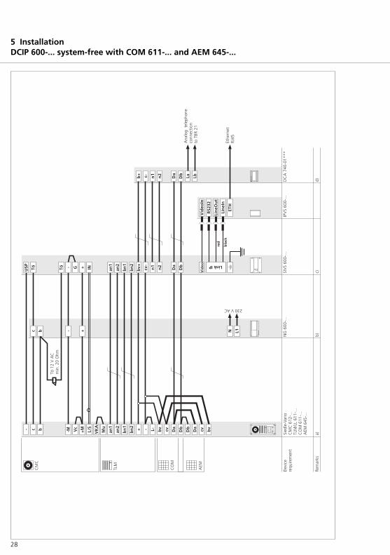
DCIP 600-... system-free withCOM 611-... and AEM 645-...
Functional characteristicsUp to 49 PC users (Software Clients)of a network can be called from thedoor station. Calling, speech anddoor release via the Software ClientDCIP SC 600-... . The SoftwareClient must be installed on every PCwhich receives door calls.For calls via the code lock module,for each user a freely selectable callnumber (max. 22 digits) can beentered. The call numbers can agree,for instance, with an existingtelephone directory.
Standard call tones for the SoftwareClient 3-tone chime. A dedicated*.wav file can be assigned for eachcall tone.It is not possible to listen in to anexisting call from other PC users inthe network.The door is opened by the called PCuser using a “virtual door releasebutton”, the light switching functionis actuated using a “virtual lightbutton”. The door call can be mutedwith an optical display on themonitor.
Supplementary functions• Up to 10 PC users can be called inparallel with a call button from thedoor station. (Note: Every PC whichreceives a parallel door call occupies2 registrations in the IPVS 600-...)
Remarksa) Door release 12 V AC, use at least20 Ohm (e.g. TÖ 615-...)b) The NG 600-0 can also take overthe power supply to existing on-sitecall buttons. A voltage of 12 V ACmax. 200 mA is available for thelighting if a door release with animpedance of at least 20 Ohm isused. With a higher currentconsumption, an additionaltransformer must be used.• 12 V AC consumers in the wiringdiagram:• Door release appr. 600 mA Camera heating appr. 100 mA• Door release contact load in theSIVS 600-... max. 24 V AC, 1 A• Light contact load in the doorloudspeaker max. 24 V AC, 2 Ac) Distance of the SIVS 600-... to thedoor station max. 200 m with J-Y(ST)Y 0.8 mm core material.Distance between the two devicesSIVS 600-... and IPVS 600-... in thedistributor max. 1 m. Duringinstallation, ensure that the doorrelease is laid in a separate cable.Power supply to the SIVS 610 15 VDC (terminal bv+/cv-), max. 300 mA.d) ***Optionally the DCA 740-01can be connected to the PBXextension of a telephone system.Active door calls can then be routedvia the telephone. The functionalfeatures of the Software Client canstill be used.

30
5 InstallationDCIP 600-... system-free with DRM 611-...
31
DCIP 600-... system-free withDRM 611-...
Functional characteristicsUp to 49 PC users (Software Clients)of a network can be called from thedoor station. Calling, speech anddoor release via the Software ClientDCIP SC 600-... The Software Clientmust be installed on every PC whichreceives door calls. For calls via the display call module,a name can be assigned to each PCuser, e.g. Anton Anyone.To scroll through the name index,there are two arrow keys providedfor "up/down". When the requiredname is highlighted in the list,pressing the button with the bellsymbol will initiate a call to this user. The DRM 611-… can also be used incombination with the COM 611-…in order to display the input via theDRM 611-...
Standard call tones for the SoftwareClient 3-tone chime. A dedicated*.wav file can be assigned for eachcall tone.It is not possible to listen in to anexisting call from other PC users inthe network.The door is opened by the called PCuser using a “virtual door releasebutton”, the light switching functionis actuated using a “virtual lightbutton”. The door call can be mutedwith an optical display on themonitor.
Supplementary functions• Connection of the COM 611-... ispossible in order to call PC users bymeans of code selection.• Up to 10 PC users can be called inparallel with a call button from thedoor station. (Note: Every PC whichreceives a parallel door call occupies2 registrations in the IPVS 600-...)
Remarksa) Door release 12 V AC, use at least20 Ohm (e.g. TÖ 615-...)b) The NG 600-0 can also take overthe power supply to existing on-sitecall buttons. A voltage of 12 V ACmax. 200 mA is available for thelighting if a door release with animpedance of at least 20 Ohm isused. With a higher currentconsumption, an additionaltransformer must be used.• 12 V AC consumers in the wiringdiagram:• Door release appr. 600 mA Camera heating appr. 100 mA• Door release contact load in theSIVS 600-... max. 24 V AC, 1 A• Light contact load in the doorloudspeaker max. 24 V AC, 2 Ac) Distance of the SIVS 600-... to thedoor station max. 200 m with J-Y(ST)Y 0.8 mm core material.Distance between the two devicesSIVS 600-... and IPVS 600-... in thedistributor max. 1 m. Duringinstallation, ensure that the doorrelease is laid in a separate cable.Power supply to the SIVS 610 15 VDC (terminal bv+/cv-), max. 300 mA.When connecting additional devicesto the Vario bus (terminals Da/Db),the Vario bus requires an additionalpower supply.d) ***Optionally the DCA 740-01can be connected to the PBXextension of a telephone system.Active door calls can then be routedvia the telephone. The functional features of theSoftware Client can still be used.

32
5 TerminalsSIVS 610-0, SIM 740-0
Block diagram SIVS 610-0
G Reference for the inputsE1–E4
E4 Input 4, call button 4 (7.4)E3 Input 3, call button 3 (7.3)E2 Input 2, call button 2 (7.2)E1 Input 1, call button 1 (7.1)cv- Power supply for bv+ Vario bus, 15 V DC, max.
300 mADa/Db Vario bus+ Supply voltage- 24 V DCTö not used, DR viaTö TLC 640-02Li not usedUSP Universal Serial Port,
SN1 RF signal, pathSN2 SIM 740-...–SIVS 610-...n1 RF signal for n2 connected
DCA 740-01
Block diagram SIM 740-0
S1 Switching output 1S2 Switching output 2S3 Switching output 3S4 Switching output 4cv- Power supply forbv+ 15 V DC1–8 Siedle MultiE1 Input 1E2 Input 2E3 Input 3Da/Db Vario busSN1 RF signal, pathSN2 SIM 740-...–SIVS 610-...

33
Cam
era
assi
gnm
ent
mod
e
6 InstallationDCIP 740-... Siedle multi

34
6 InstallationDCIP 740-... Siedle multi
Mon
itor
assi
gnm
ent
mod
e

35
DCIP 740-... Siedle multi
Functional characteristicsDepending on the operating modecamera assignment or monitorassignment, 4 or 49 PC users can becalled.
Calling, speech and door release viathe Software Client DCIP SC 600-... .The Software Client must beinstalled on every PC which receivesdoor calls. Standard call tones forthe Software Client 3-tone chime. Adedicated *.wav file can be assignedfor each call tone. It is not possible to listen in to anexisting call from other PC users inthe network.The door is opened by the called PCuser using a “virtual door releasebutton”, the light switching functionis actuated using a “virtual lightbutton”. The door call can be mutedwith an optical display on themonitor.
Camera assignment mode The SIM 740-... is assigned to a door/ camera. In this mode, the devicecan be assigned up to 49 differentcall destinations, i.e. Siedle Multisystem addresses which correspondto the functions of 49 Multitelephones. In this operating mode,a DCIP 740-... is required for eachdoor. This operating mode isadvisable in systems with a smallnumber of doors and a largenumber of PC users.
Monitor assignment mode: Up to a maximum of 4 calldestinations, i.e. Siedle Multi systemaddresses, can be assigned to theinterface. These correspond to thefunctions of the 4 Multi telephones.The call destination can be dialledfrom every door within the SiedleMulti (max. 254). This operatingmode is advisable in systems with alarge number of doors and a smallnumber of PC users.
Remarksa) Door release 12 V AC, use at least20 Ohm (e.g. TÖ 615-...)• 12 V AC consumers in the wiringdiagram:• Door release appr. 600 mA• Light contact load in the doorloudspeaker max. 24 V AC, 2 Ac) Distance of the SIVS 610-... to thedoor station max. 200 m with J-Y(ST)Y 0.8 mm core material.Distance between the two devicesSIVS 610-... and IPVS 600-... in thedistributor max. 1 m. Duringinstallation, ensure that the doorrelease is laid in a separate cable.Power supply voltage bv+/cv- of theSIVS 610 15 V DC, max. 300 mAWhen connecting additional devicesto the Vario bus (terminals Da/Db),the Vario bus requires an additionalpower supply.d) ***Optionally the DCA 740-01can be connected to the PBXextension of a telephone system.Active door calls can then be routedvia the telephone. The functional features of theSoftware Client can still be used.

36
Commissioning of the DCIP 600-... isbroken down into three steps:1 Configuration of IPVS 600-...2 Configuration of SIVS 600-...3 Installation of the software DCIP SC 600-... on the PCs
Step 1 on this pageConfiguration of IPVS 600-...Issue of the IP address, subnet maskaddress and gateway address forassignment in the network. In case of group calls, issue of theMulticast address.
Step 2 on pages 40-41Configuration of SIVS 600-...Assignment of the IWA addressesfrom the call buttons to thesubsequent PC users. When usingadditional modules such as the codelock module or display call module,these are also configured at thisstage. After completion ofprogramming, a file (*.dcip) iscreated for the Software Client.
Step 3 on pages 42-43Installation of the SoftwareClientsThe Software Client has to beinstalled on the PC users in thenetwork. Import of the generatedfile (*.dcip). Selection of addressesto be signalled on the affected PCuser.
7 CommissioningDCIP 600-... system-free
Step 1
Issue of the IP address andsubnet mask in the IPVS 600-...• The connection can be establishedusing a crossover network cable. TheIPVS 600-... can also be addressedvia the network if the PC andIPVS 600-.. are located in the sameaddress area.• Start the Internet Explorer on thePC and enter the following in theaddress line:http://192.168.0.1The IP settings in the as-deliveredstatus of the IPVS 600-...IP address 192.168.0.1Subnet mask 255.255.255.0Gateway address 0.0.0.0User name: ServicingPassword: None issued ondelivery• The user interface is opened.• In the user interface, select themenu point Settings.• On the left-hand side, select themenu point Service parameters.• Click the submenu Network . Onthe right-hand side, the relevantsettings are opened up.• The following settings can beperformed for operation in thenetwork.IP addressSubnet mask addressVideo transmissionHTTP browser portType of network connection
Connection of the PC to IPVS 600-...
Changes to the IP address or subnetmask address are transmitted to thedevice by clicking on the Set button.However, these only become validafter restarting the device.
• After entering a new IP address,click onto the Set button.• Enter the old IP address in theaddress line of the web browser,followed by /reset (for example192.168.0.11/reset). The IPVS isrestarted and can subsequently onlybe reached using the new IPaddress.

37
7 CommissioningDCIP 740-... Siedle multi
The procedure for commissioningthe DCIP 740-... is somewhat moreextensive than for the DCIP 600-... Intotal 4 steps have to be performed.1 Configuration of IPVS 610-...2 Configuration of SIM 740-...3 Configuration of SIVS 600-...4 Installation of the software DCIP SC 600-... on the PCs
Step 1 on this pageConfiguration of IPVS 610-...Issue of the IP address, subnet maskaddress and gateway address forassignment in the network. In thecase of group calls, issue of theMulticast address.
Step 2 on pages 38-39Configuration of SIM 740-...Here, the multi-specific parametersof the SIM 740-... are entered.Selection of whether the DCIP 740-... should run in thecamera or the monitor mode.
Step 3 on pages 40-41Configuration of SIVS 610-...Assignment of Multi bus addresses(now IWA address) to subsequentPC users.Additional modules such as the codelock module or display call moduleare programmed at the TLC 640-... .After completion of programming, afile (*.dcip) is created for theSoftware Client.
Step 4 on pages 42-43Installation of the SoftwareClientsThe Software Client has to beinstalled on the PC users in thenetwork. Import of the generatedfile (*.dcip). Selection of addressesto be signalled on the affected PCuser.
Step 1
Issue of the IP address andsubnet mask in the IPVS 610-...• The connection can be establishedusing a crossover network cable. TheIPVS 610-... can also be addressedvia the network if the PC andIPVS 610-... are in the same addressarea.• Start the Internet Explorer on thePC and enter the following in theaddress line:http://192.168.0.1The IP settings in the as-deliveredstatus of the IPVS 610-...IP address 192.168.0.1Subnet mask 255.255.255.0Gateway address 0.0.0.0User name: ServicingPassword: None issued ondelivery• The user interface is opened..• In the user interface, select themenu point Settings.• On the left-hand side, select themenu point Service parameters.• Click the submenu Network. Onthe right-hand side, the relevantsettings are opened up.• The following settings can beperformed for operation in thenetwork.IP addressSubnetmask addressGateway addressVideo transmissionHTTP browser portType of network connection
Changes to the IP address, subnetmask address or gateway addressare transmitted to the device byclicking on the Set button. However,these only become valid afterrestarting the device.
• After entering a new IP address,click onto the Set button.• Enter the old IP address in theaddress line of the web browser,followed by /reset (for example192.168.0.11/reset). The IPVS isrestarted and can subsequently onlybe reached using the new IPaddress.
Connection of the PC to IPVS 600-...

38
7 ConfigurationSIM 740-... (only with DCIP 740-...)
Configuration of SIM 740-...Programming the SIM 740-... takesplace using a connected PC via serialPRI 602-... and SIVS 610-...The SIM 740-... is selected in theconfiguration softwareDCIP CO 600-... The SIM 740-... can be used in two operating modes(camera assignment and monitorassignment). The operating modedepends on the application and thesystem topology.The required operating mode isselected in the first mask.
Basic parameters
Master monitor addressThis address is one of the addresseswhich can be selected under thenext tab (SIM addresses). Using thisaddress, the SIM 740-... can beaccessed for servicing purposes. Ifthere are several SIM 740-... units ina Multi system, ensure that eachSIM 740-... is given a differentmaster monitor address.
Speech channelsSelect the installed speech channel.Please note:In group systems, speech channel 2must be switched off.
Upgrade stageIn stage 1, address area from 1 -254, only speech channel 1 and 2are allowed. Application in oldersystems, e.g. with HT 641/642/643.In step 2, address area from 1 - 500,speech channel 1 and 2, or speechchannel 1 and the group speechchannel are allowed. For current applications, e.g. withHT 740-..., HT 840-...
SIM addressesIn the mask SIM addresses, thephysical Multi bus addresses areselected under which you wish to beable to reach the SIM 740-... or therelevant PC users.The master monitor address isalready entered. The DCIP Software Client is the PCon which a Siedle in-housetelephone is depicted by thesoftware.When using the “monitorassignment” mode, 3 additionaladdresses can be selected. When using the camera assignmentmode, 48 additional addresses canbe selected.
The functions 1 - 256 correspond tothe virtual buttons 1 - 256.
Each of these functions (buttons)can be assigned a command.
FunctionsIn the Functions mask, only remoteswitching functions can be assigned.Parameters 1-9 correspond to theremote switching functions 1-9 onthe Multi bus. In the Multi systemvarious devices can be programmedfor this remote switching function inorder to initiate an action. (e.g.FSM 740-...)The functions 10 - 256 are intendedfor future applications.
MessagesIn the Messages mask, statusmessages are configured which aredisplayed in the Software Client. Inthe Multi system, status messages 1-8 exist in addition.The statuses ON and OFF aretransferred. Each of these messagescan be assigned to an individual text.
Free text inputDisplay of texts at the Software-Client. Example Display of three statuses inthe Software-Client.Messages in the Multi system areonly transmitted when a status ischanged.After power ON, the status isunknown. In this case, the status"Not initialised" is displayed at theSoftware Client. Only when thestatus is changed for the first time isthe current status displayed.

39
7 ConfigurationMulticasting
MulticastingAlongside the 1:1 connectionbetween one encoder and onereceiver (Unicast) the IPVS 600-...also offers facility for severalsoftware clients to receive the videosignal at the same time. This takesplace either by duplicating the datastream in the IPVS 600-... andsubsequent distribution over severalsoftware clients (multi-unicasting) orby distribution of an individual dataflow in the network itself to severalrecipients in a defined group(multicasting). For each encoder(video input) it is possible to enter aseparate multicasting address eachper stream and to enter the relevantport. It is possible to changebetween the streams by clicking onthe relevant index tab.
NoteThe requirement for multicastingoperation is a network withmulticasting capability using the UDPprotocol and the IGMP protocol.Other group management protocolsare not supported. The TCP protocoldoes not support multicastconnections. The requirement formulticast operation in a networkwith multicasting capability is theset-up of a special IP address (class Daddress).
The network must support the set-up of a group IP address and theInternet Group ManagementProtocol (IGMP V3). The addressarea is 225.0.0.0 to239.255.255.255.
The multicast address can be thesame for several streams. However,in this case it is necessary to use adifferent port in each case to ensurethat several data streams are nottransmitted simultaneously via thesame port and the same multicastaddress.
The settings must be enteredseparately for each encoder (videoinput) and each stream.
Multicast address video 1Enter a valid multicast address foreach stream of the relevant encoder(video input) which you wish towork in the multicast mode(duplication of the data streams inthe network). With the setting0.0.0.0, the encoder works for therelevant stream in the multi-unicastmode (copying the data streams inthe device). The IPVS 600-...supports multi-unicast connectionsfor up to five recipients connectedsimultaneously. Duplication of thedata in the device requires highcomputing power and cancompromise image quality undercertain circumstances.
Port:With simultaneous data streams tothe same multicast address, the datastreams must be assigned todifferent ports.Enter the port address of therelevant stream here.
StreamingClick in the checkbox in order toactivate multicast streamingoperation for the relevant stream.An activated stream is marked witha tick.
Multicast audio port 1Alongside video data, audio signalscan also be transmitted andreceived. Audio transmission takesplace in a separate data stream inparallel to the video data and soincreases the network load. Theaudio data is encoded in accordancewith G.711 and requires anadditional bandwidth of appr. 80kBit/s per direction.
If audio signals have to betransmitted in multicasting mode,these must be assigned to their ownport as this is a separate datastream. Enter the port address of therelevant stream here.
Audio signals are only transmitted ifthe audio settings and audiofunction are switched on in theconfiguration.
Multicast package TTLA value can be entered whichdetermines how long the multicastdata packages are active in thenetwork. If multicasting is operatedvia a router, the value must begreater than 1.
40
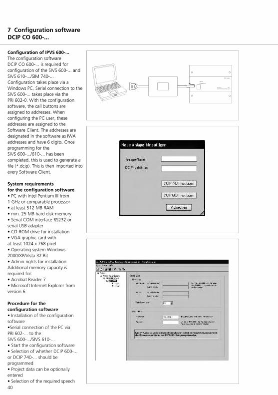
Configuration of IPVS 600-...The configuration softwareDCIP CO 600-... is required forconfiguration of the SIVS 600-... andSIVS 610-.../SIM 740-...Configuration takes place via aWindows PC. Serial connection to theSIVS 600-... takes place via thePRI 602-0. With the configurationsoftware, the call buttons areassigned to addresses. Whenconfiguring the PC user, theseaddresses are assigned to theSoftware Client. The addresses aredesignated in the software as IWAaddresses and have 6 digits. Onceprogramming for the SIVS 600-.../610-... has beencompleted, this is used to generate afile (*.dcip). This is then imported intoevery Software Client.
System requirementsfor the configuration software • PC with Intel Pentium III from1 GHz or comparable processor• at least 512 MB RAM• min. 25 MB hard disk memory• Serial COM interface RS232 orserial USB adapter• CD-ROM drive for installation • VGA graphic card with at least 1024 x 768 pixel• Operating system Windows2000/XP/Vista 32 Bit• Admin rights for installationAdditional memory capacity isrequired for:• Acrobat Reader 7• Microsoft Internet Explorer fromversion 6
Procedure for the configuration software• Installation of the configurationsoftware•Serial connection of the PC viaPRI 602-... to the SIVS 600-.../SIVS 610-...• Start the configuration software• Selection of whether DCIP 600-...or DCIP 740-... should beprogrammed• Project data can be optionallyentered• Selection of the required speech
7 Configuration softwareDCIP CO 600-...
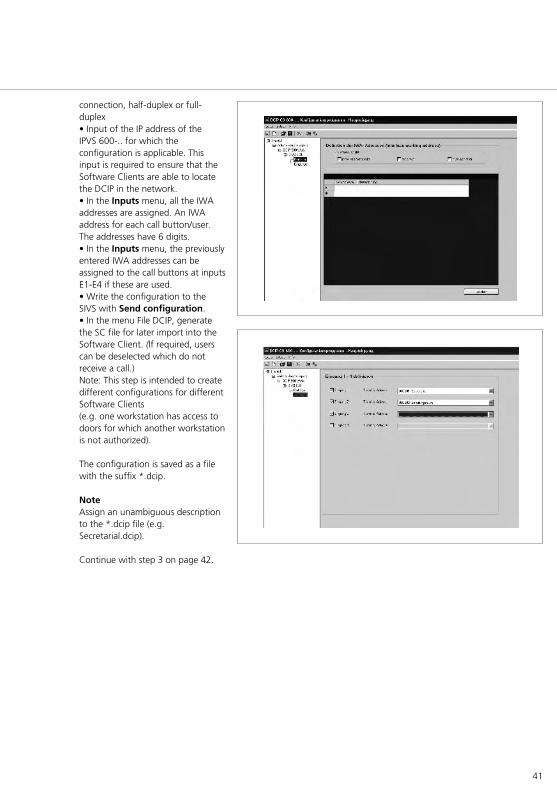
41
connection, half-duplex or full-duplex• Input of the IP address of theIPVS 600-.. for which theconfiguration is applicable. Thisinput is required to ensure that theSoftware Clients are able to locatethe DCIP in the network.• In the Inputs menu, all the IWAaddresses are assigned. An IWAaddress for each call button/user.The addresses have 6 digits.• In the Inputs menu, the previouslyentered IWA addresses can beassigned to the call buttons at inputsE1-E4 if these are used.• Write the configuration to theSIVS with Send configuration.• In the menu File DCIP, generatethe SC file for later import into theSoftware Client. (If required, userscan be deselected which do notreceive a call.)Note: This step is intended to createdifferent configurations for differentSoftware Clients (e.g. one workstation has access todoors for which another workstationis not authorized).
The configuration is saved as a filewith the suffix *.dcip.
NoteAssign an unambiguous descriptionto the *.dcip file (e.g.Secretarial.dcip).
Continue with step 3 on page 42.

42
7 Client-SoftwareDCIP SC 600-...
Installation of the SoftwareClientsThe Software Client DCIP SC 600-...must be installed on every PC youwish to receive door calls. TheSoftware Client communicates withthe calling station, the DCIP 600-...After installation, the file (*.dcip)generated using the configurationsoftware must be imported.Theaddresses to which the client isintended to respond are selectedfrom the imported file.
System requirementsfor the Software Client• Operating system MicrosoftWindows XP/Vista 32/64 BitWindows 7 32/64 Bit • Pentium IV from 2 GHz orcompatible CPUs• min. 1 GB RAM (64 Bit min. 2GB)• Graphic card with at least 1024 x 768, 128 MB and 16 bit colour depth • 100 Mbit Ethernet card• Sound card• Microsoft DirectX 9.0c or newer• Microsoft Internet Explorer fromVersion 6.0 to read the help
Procedure for installation• Install the DCIP SC 600 software• It may be necessary to installadditional programs such asMicrosoft DirectX Version 9.0c.• Start the Software Client• The Software Client configurationcan be opened by pressing the right-hand mouse button on the virtual in-house telephone.• In the first tab Configuration,select add DCIP SC file “0” andimport the file exported by theconfiguration software (*.dcip).• It is then possible under DCIP SC-Edit file to assign an IWAaddress to the Software Client forthe relevant DCIP 600-..., to whichyou wish the PC to respond.• Other IWA addresses canoptionally be assigned to theSoftware Client 2. (e.g. for receivingan additional door call).
Licence regulationsFor each installation of the SoftwareClient on a PC, a licence is required for the DCIP SC 600-0.

43
Possible error sources• No speech connection from the PCto the door. The microphoneamplifier may not be activated.• Installation must take place asadministrator, so that all registeredusers have access to the SoftwareClient later.• Marked echo on the line in speechmode. In the Windows volume regulationfor sound reproduction, Sound offmust be activated under themicrophone controller. This selectionprevents the PC microphone signalbeing reproduced in the PCloudspeaker.• The other party is not audible atthe PC.Possible causes: • No loudspeaker connected at thePC/monitor• No driver for the sound card• The loudspeaker is set to muteunder the audio properties. (sound off)• If there is an active firewall, theapplication fileDCIP SC 600-0.exe must be definedas an exception or as a permanentlyauthorized program/application.• In order to establish a video link, itmay be necessary, for the drivers forthe used graphic card to be updatedto the latest status.
Other settings in the SoftwareClient:
Free buttonsSelection of functions for buttons 1–3. Each button can be assigned anindividual inscription text.
Call tonesSelection of call tones for door calland internal call. Alternatively, youcan select your own *.wav files.Setting the volume for call tones
Speech volumeSetting the speech volume.Loudspeakers and microphones canbe separately set. It may benecessary to carry out other settingsin the control panel under “Sound”.
GeneralSelection of the Software Clientlanguage.“Start application automatically afterlogging onto the system?”

44
8 Setting the speech volumeLevel adjustment DCIP 600-...
Level adjustment IPVS 600-...Setting the volume of the PC user inthe direction of the door station.
• At the back of the TLM/LL 611-...,set the potentiometer “Volume“ tothe middle setting, “Boost” switchoff (as-delivered status).• Establish a connection to a PCuser.• At the PC, open the menu“Software Client configuration” andselect the tab “Speech volume“.• Using the “Microphone“controller, starting from 0% set thevolume in the direction of the doorso that when a person speaks loudlyinto the microphone of the receiveror headset, no distortion is audibleat the door loudspeaker.As a rule, the optional fieldmicrophone amplifier remainsswitched on. This field can only beswitched off in the case ofmicrophones with a very high outputlevel.• At the TLM/LL 611-0 use thepotentiometer “Loudspeaker“ or theboost function to set the optimumvolume.
Level adjustment TLM/LL 611-... Setting the volume of the PC userfrom the door station in thedirection of the PC user.
• At the back of the TLM/LL 611-...,set the “microphone“ potentiometerto the middle setting (as-deliveredstatus).• Establish the connection to the PC.• At the PC, select Reproduction inthe Speech volume menu.Ensure that “Tone off“ has beenselected under the headingMicrophone.• Using buttons + and –, set theoptimum volume starting from 0%.• To ensure that the levels arestored, these must be performed viathe configuration menu.
Level adjustment DCA 740-...Set the volume of the speechconnection to the telephone system.
• At the back of the TLM/LL 611-...,set the potentiometer “Volume“ tothe middle setting, “Boost” switchoff (as-delivered status).• Establish the link to the TC systemor public network telephone.• With potentiometer P1 in theDCA 740-01, set the optimumvolume at the door.If applicable, regulate the“Loudspeaker“ potentiometer or usethe boot function to achieve therequired volume. • With potentiometer P2 in theDCA 740-0, set the optimumvolume in the receiver.(Comparison: Normal volumes withpublic network calls).If applicable, regulate the“Microphone” potentiometer at theTLM/LL 611-0, in order to achievethe required volume.

45
Level adjustment IPVS 610-...Setting the volume of the PC user inthe direction of the door station.
• Set the optimum volume at thedoor loudspeaker for Siedle Multiusers.• Establish the connection to the PC.• At the PC, open the configurationmenu of the Software Client andselect the tab “Speech volume“.• Using the “Microphone“controller, starting from 0% adjustthe volume in the direction of thedoor in such a way that the samevolume is achieved as for the SiedleMulti users.As a rule, the optional fieldmicrophone amplifier remainsswitched on. This field can only beswitched off in the case ofmicrophones with a very high outputlevel.• If the control range of themicrophone controller is notsufficient to achieve an optimumvolume in the door loudspeaker, theSIM 740-0 with SW1 offers a switchfor level selection.SW1:OFF = 0 dB (as-delivered status)ON = +9 dB
Level adjustment TLM 645-...Setting the volume of the PC userfrom the door station in thedirection of the PC user.
• Establish the connection to the PC.• At the PC, select Reproduction inthe volume menu.Ensure that “Tone off“ has beenselected under the headingMicrophone.• Using buttons + and –, set theoptimum volume (starting from 0%).• To ensure that the levels arestored, these must be performed viathe configuration menu.
8 Setting the speech volumeLevel adjustment DCIP 740-...
Level adjustment DCIP 740-0-... Set the volume of the speechconnection to the telephone system.
• Set the optimum volume at thedoor loudspeaker for Siedle Multiusers.• Establish the link to the TC systemor public network telephone.• Using potentiometer P1 in theDCA 740-01, set the optimumvolume at the door. If applicable, theswitch SW1 in the SIM 740-0 mustbe set to ON.• With potentiometer P2 in theDCA 740-0, set the optimumvolume in the receiver.(Comparison: Normal volumes withpublic network calls).
46
9 DoorComDCA 740-01
The DoorCom Analog DCA 740-... isused as an interface betweenDoorCom IP and an analogtelephone connection of atelecommunication system.
Up to 49 call destinations (addresses)can be assigned to the DCA 740-...The functionality depends in themain on the capability of thetelephone system / on thetelephones connected to it.The assignment and functionalitycan be programmed in the SIVS 600-.../SIVS 610-...The selection of users and controland switching functions takes placeby means of DTMF dialling. Thetelecommunications system and theconnected telephones musttherefore possess DTMF diallingcapability.
Power supplyThe DCA 740-... is supplied directlyfrom the SIVS 600-.../SIVS 610-...A separate supply is consequentlynot required. The power to the a/bpublic network interface is suppliedfrom the telecommunication systemor the a/b public networkconnection from the exchange. It isnot possible to connect an individualpublic network telephone directly tothe a/b line of the DCA 740.
10 DoorCom IPFactory setting IPVS 600-...
With the reset button at theIPVS 600-..., it can be reset to theas-delivered status. It is essential toload the Siedle factory configurationin the IPVS 600-... after a reset. Proceed as follows.1 Open the Internet Explorer.2 Access the video server (IPVS) withits IP address3 Access the following menus insequence: SettingService parametersFirmware and configuration upload 4 Under Configuration upload,select the configuration file with"search..." The file is on the supplied CD.5 Select the file with the rtc_imagewith upload. Using the Upload button, start theupdate.
47
11 Glossary Index
AEM 645-... 11BTM 650-... 10CMC 612-... 11, 19COM 611-... 11DCA 740-... 12, 44DCIP CO 600-... 13DCIP SC 600-... 13DRM 611-... 11IPVS 600-... 12, 16NG 600-... 12PRI 602-... 12SIM 740-... 15, 32SIVS 600-... 14, 16SIVS 610-... 15, 32TLC 642-... 15TLM/LL 611-0 14, 18TM 612-... 10TME 640-... 10TME 645-... 10VMS 641-... 15
The current issue of the “ DoorCom IP “ system manual isavailable from the download areaunder www.siedle.de.
Technical additions and printingerrors do not constitute grounds forany claims to damages.
Connection 20As-delivered status 46Block diagram 18, 32Camera assignment 6, 8Client 8, 42Commissioning 36Config 36Cross-over 36DoorCom 12Factory setting 46Full duplex 8HTTP 8IP 8IP address 8IWA 8LAN 8LED display 17Licences 13, 42Line rectifier 12Monitor assignment 7, 8Multi 6, 34Multicasting 8, 39Network cable 36Power supply 4, 6Programming 36Push to talk 8Reset 46RS232 8RS485 8Server 8Siedle Multi 6, 34Software Client 40Subnet mask 8System interface video server 11System requirements 40, 42System-free 4, 9TCP 8Terminals 18, 32UDP 9Vario bus 9Web browser 36Wiring diagram 20
© 2007/12.10Printed in GermanyOrder no. 0-1101/039822 EN
S. Siedle & Söhne
Postfach 1155D-78113 FurtwangenBregstraße 1D-78120 Furtwangen
Tel. +49 7723 63-0Fax+49 7723 [email protected]