
System Galaxy to PIM-485 Guide Schlage ODT-PIM (10.4).pdf · Schlage Guide . Configuring the...
50
System Galaxy Quick Guide CONFIGURATION AND OPERATION IR SCHLAGE WIRELESS Republished SG 10.4 OCT 2014 WIRELESS READERS & LEGACY ODT PIMS LEGACY IR-SCHLAGE ODT PIM WITH WIRELESS READERS Page 1
Transcript of System Galaxy to PIM-485 Guide Schlage ODT-PIM (10.4).pdf · Schlage Guide . Configuring the...
System Galaxy Quick Guide CONFIGURATION AND OPERATION
IR SCHLAGE WIRELESS
Republished
SG 10.4 OCT 2014
WIRELESS READERS & LEGACY ODT PIMS
LEGACY IR-SCHLAGE ODT PIM WITH WIRELESS READERS
Page 1
System Galaxy
Schlage Legacy ODT
Integrating System Galaxy with Legacy Schlage Wireless
Readers & ODT PIMS
with RS-485 Serial Communication using a Galaxy 635-CPU & 635 DSI Board
Information in this document is subject to change without notice. No claims are made as to the accuracy or completeness of this document.
This document describes how to wire & configure the Aperio Readers and Communication Hubs to work with the Galaxy DSI RS-485 Board, as well as how to program wireless readers into the System Galaxy software. This guide does not supersede the manufacturer’s documentation for installing its products, which are not manufactured by Galaxy Control Systems.
2nd Edition 10.4 Copyright © 2014 Galaxy Control Systems All rights reserved
Galaxy Control Systems
3 North Main Street
Walkersville MD 21793
301-845-6600
www.galaxysys.com
No part of this document may be reproduced, copied, adapted, or transmitted, in any form or by any means, electronic or mechanical, for any purpose, without the express written consent of Galaxy Control Systems. Copyright protection claims include all forms and matters of copyrighted material and information, including but not limited to, material generated from the software programs, which are displayed on the screen such as icons, look and feel, etc.
Microsoft®, Windows®, Windows NT®, Active Directory®, MS-DOS®, SQL Server®, and Windows Server System®, are registered trademarks of the Microsoft Corporation in the U.S. and other countries.
IR, Ingersoll-Rand, Schlage® , Schlage Wyreless™ are trademarks and/or registered trademarks of their respective owners. Adobe® and Acrobat® are registered trademarks of Adobe Systems Inc. Technical illustrations are creations of the technical author.
Page 2

System Galaxy
Schlage Guide
Configuring the IR/Schlage PIM-OTD-485 for use with the 600-series DSI Board
Information in this document is subject to change without notice. No claims are made as to the accuracy or completeness of this document. This document does not supersede any instructional documentation for products not manufactured by Galaxy Control Systems. This document describes simple set up to interface the Schlage PIM-OTD-485-RS to the Galaxy DSI Board’s 485 port, as well as how to configure wireless readers into the System Galaxy software.
2nd edition
Copyright © 2008 Galaxy Control Systems All rights reserved
Galaxy Control Systems
3 North Main Street
Walkersville MD 21793
301-845-6600
www.galaxysys.com
No part of this document may be reproduced, copied, adapted, or transmitted, in any form or by any means, electronic or mechanical, for any purpose, without the express written consent of Galaxy Control Systems. Copyright protection claims include all forms and matters of copyrighted material and information, including but not limited to, material generated from the software programs, which are displayed on the screen such as icons, look and feel, etc.
Microsoft®, Windows®, Windows NT®, Active Directory®, MS-DOS®, SQL Server®, and Windows Server System®, are registered trademarks of the Microsoft Corporation in the U.S. and other countries.
IR, Ingersoll-Rand, Schlage® , Schlage Wyreless™ are trademarks and/or registered trademarks of their respective owners. Adobe® and Acrobat® are registered trademarks of Adobe Systems Inc. Technical illustrations are creations of the technical author.
Page 3
Table of Contents
1 Introduction.......................................................................................................... 8 1.1 What is a PIM-OTD-485? ....................................................................................................... 9
1.1.1 How does the PIM work with System Galaxy? ........................................................... 9 1.2 What is a WAPM and how does it work?............................................................................. 9
1.2.1 How does the WAPM handle card reads?.................................................................. 9 1.2.2 When does the WAPM initiate communication to the PIM? ....................................... 9 1.2.3 How are the PIM and WAPM configured?.................................................................. 9
1.3 Sample Diagrams of integration with PIM-485-OTD......................................................... 10 1.4 Requirements ....................................................................................................................... 12
1.4.1 For System Galaxy you need the following things:................................................... 12 1.4.2 Field Wiring Specifications for RS-485: .................................................................... 12 1.4.3 LAN Wiring Specifications for Control Panel: ........................................................... 12 1.4.4 To install the PIM & WAPMs you need the following things:.................................... 13
1.5 Getting Started..................................................................................................................... 14 1.5.1 About determining the best mounting location for the PIM....................................... 14 1.5.2 About determining the location of the 600-series Panel........................................... 14
1.6 Installing is the Configuration Demo Tool (CDT) ............................................................. 15
2 Configuring the PIM/WAPMs using the CDT ................................................... 16 2.1 Connecting the PIM to the CDT.......................................................................................... 16 2.2 Getting the PIM in Link Mode with the CDT tool............................................................... 17 2.3 Setting the PIM Address & Address Range for WAPMs.................................................. 18 2.4 Initiating the WAPM Link to the PIM .................................................................................. 19 2.5 Linking the WAPM to the PIM ............................................................................................. 20 2.6 Testing WAPM (door) with the CDT ................................................................................... 22 2.7 The Activity Log in the CDT................................................................................................ 22 2.8 Configuring the WAPM (door access point) with the CDT .............................................. 23 2.9 Setting the WAPM Heartbeat .............................................................................................. 24 2.10 Setting the card swipe First, Delay and Retry timers....................................................... 25 2.11 Setting the WAPM Re-Latch Time...................................................................................... 26 2.12 Setting Card Conversion..................................................................................................... 27 2.13 Setting the MODE................................................................................................................. 27 2.14 Setting the Latch Type ........................................................................................................ 28 2.15 Setting the Extended Unlock option.................................................................................. 29 2.16 Setting the RXT (request to exit) option............................................................................ 30 2.17 Setting the RXT SIFT option ............................................................................................... 31 2.18 Setting the MAG Track option ............................................................................................ 32 2.19 Setting the Fail Safe Options.............................................................................................. 33 2.20 Setting the Cache Mode options........................................................................................ 34 2.21 Setting the Pre-Alarm and Door Held options .................................................................. 35
Page 4

3 Configuring System Galaxy .............................................................................. 37 3.1 About Installing the SG Software....................................................................................... 37 3.2 About Installing the 600-series Hardware ......................................................................... 38 3.3 Configuring the 600 Controller and DSI in the software.................................................. 40
3.3.1 About Using System Galaxy software ...................................................................... 40 3.3.2 Signing-in to the System Galaxy software................................................................ 40 3.3.3 Registering Wireless Readers in System Galaxy ..................................................... 41 3.3.4 Adding the Loop/Cluster in System Galaxy .............................................................. 42 3.3.5 Adding the 600 Controller & DSI Board in System Galaxy....................................... 43 3.3.6 Configuring the Serial Channels in System Galaxy.................................................. 45
3.4 Configuring the RF Reader Properties in System Galaxy ............................................... 47 3.4.1 Setting Reader Properties from System Galaxy....................................................... 47 3.4.2 Setting General Properties from System Galaxy...................................................... 48 3.4.3 Setting Reader Schedules from System Galaxy ...................................................... 49 3.4.4 Setting Reader Alarm Options from System Galaxy ................................................ 50
Page 5

List of Tables and Figures
Figure 1 – Concept Diagram: Integrating PIM-OTD-485 to System Galaxy 600-series panels .............. 8 Figure 2 – Configuration examples of PIM-485-OTD interface to 600-Series DSI 485 Channel .......... 10 Figure 3 – Door/WAPM ID Numbering scheme..................................................................................... 11 Figure 4 – Screen shot of the Schlage Configuration Tool (CDT) ......................................................... 15 Figure 5 – PIM Status tab: selecting COM port to connect to PIM ........................................................ 16 Figure 6 – PIM Status tab: Connection Recognition for COM port to PIM ............................................ 17 Figure 7 – Addresses tab: Setting Addresses for the PIM..................................................................... 18 Figure 8 – Link tab: Setting the WAPM ‘Panel’ Number ........................................................................ 19 Figure 9 – Example of WAPM/MIRL Door Hardware ............................................................................ 21 Figure 10 – Status tab: Testing the door/reader .................................................................................... 22 Figure 11 – Activity tab: Example of the Activity Log............................................................................. 22 Figure 12 – Configuration tab: Getting WAPM Configuration ................................................................ 23 Figure 13 – Configuration tab: Setting the WAPM Heartbeat ................................................................ 24 Figure 14 – Configuration tab: Setting the Card Read Timing............................................................... 25 Figure 15 – Configuration tab: Setting the Re-latch options .................................................................. 26 Figure 16 – Configuration tab: Setting the Card Conversion................................................................. 27 Figure 17 – Configuration tab: Setting the Mode ................................................................................... 27 Figure 18 – Configuration tab: Setting the Latch Type .......................................................................... 28 Figure 19 – Configuration tab: Setting the Extended Unlock option...................................................... 29 Figure 20 – Configuration tab: Setting the RXT (request to exit) option................................................ 30 Figure 21 – Configuration tab: Setting the RXT SIFT option ................................................................. 31 Figure 22 – Configuration tab: Setting the MAG Track option............................................................... 32 Figure 23 – Configuration tab: Setting the Fail Safe Options ................................................................ 33 Figure 24 – Configuration tab: Setting the Cache Mode options........................................................... 34 Figure 25 – Configuration tab: Setting the Pre-Alarm and Door Held options....................................... 35 Figure 26 – Wiring Diagram: DSI RS-485 channel to PIM-485 connector ............................................ 39 Figure 27 – Sign On/Off: Logging into System Galaxy .......................................................................... 40 Figure 28 – Loop/Cluster Properties: Configuring the Loop .................................................................. 42 Figure 29 – Controller Properties: Configuring the 600-series Controller.............................................. 44 Figure 30 – Serial Channel Properties: Configuring the DSI’s Serial Channels .................................... 46 Figure 31 – Reader Properties: Configuring the Reader Name............................................................. 47 Figure 32 – Reader Properties: Configuring the General Options......................................................... 48 Figure 33 – Reader Properties: Configuring the Timing/Schedules ...................................................... 49 Figure 34 – Reader Properties: Configuring the Alarm Options ............................................................ 50
Page 6

DOCUMENT HISTORY DATE HISTORY
SG 8 1st Edition published.
OCT 16, 2014 Republished for SG10.4 Release, included adding instructions and requirements for the system registration for branded wireless locks.
Page 7

1 Introduction
This manual provides specific instructions for configuring a System Galaxy 600-series Access Control Panel to work with the Schlage Panel Interface Module (PIM-OTD-485-RS) and wireless access points (WAPMs/doors). This manual covers the portion of the System Galaxy software programming that is specific to the PIM interface. The main software manual covers SG in full.
System Galaxy uses the following system components to interface with a PIM on RS-485 protocol.
System Galaxy software v8.2.3 (or higher) 600-series Controller (access control panel)
– CPU Board - with v1.74d S28 flash code (or higher) – DSI Board - with v2.12a flash (or higher) using the RS485 port
Supports 1-16 doors/WAPMs per RS-485 channel – two 485 channels per board. – DIO Board (optional) only used if door alarms will trigger outputs
Figure 1 – Concept Diagram: Integrating PIM-OTD-485 to System Galaxy 600-series panels
Page 8

1.1 What is a PIM-OTD-485? PIM stands for Panel Interface Module. The PIM converts RS-485 protocol to RF protocol (and visa-versa), making it possible to integrate wireless access points (WAPMs) to System Galaxy access control panels and software.
1.1.1 How does the PIM work with System Galaxy?
System Galaxy (SG) software communicates with 600-series Access Control Panels via TCP/IP. The 600-panels use RS485 to communicate with the PIM (see Figure 1). Events from the PIM go back to the 600-panel and are logged to the SG software and database.
SG software updates a 600-panel with the programming (i.e. cards, access rules, schedules) for all the doors (wireless access points). The 600-panel stores this programming in memory. When a PIM sends a card swipe to a 600-panel, the panel returns the appropriate access decision based on rules in its memory. If a door is affected by a schedule or holidays, then the 600-panel sends the lock and unlock commands to the PIM at the appropriate time.
The PIM holds instructions from a 600-panel until the reader is ready to transmit/receive data. A card swipe, delay/retry timer, requet to exit, and heartbeat are typical types of activity that prompt the reader to contact the PIM for data/access rules. The PIM does not initiate connections to the wireless reader.
1.2 What is a WAPM and how does it work? WAPM stands for Wireless Access Point Module. It refers to the access hardware at the door. This includes the wireless reader module (RF receiver/transmitter, antenna, battery) and lock/motor, entrance lever, exit/request lever and possibly a request to enter button (see Fig. 9).
1.2.1 How does the WAPM handle card reads?
When a card is presented at a door, the WAPM sends the access request and card data to the PIM. The PIM forwards the data to the 600-Panel. The panel returns the access decision back to the PIM. The WAPM picks up the decision on the retry timer.
A WAPM timer determines the number of retries and amount of delay between retries (in milliseconds) to be used. It is important to set these values high enough to allow the PIM time to query the access control panel. The number of retries should be at least 3 or 4 and the delay should be at least 100 ms.
1.2.2 When does the WAPM initiate communication to the PIM?
Communications are always initiated by the WAPM either when the heartbeat elapses or when activity is detected at the door (e.g. card swipe, request to exit, door contact open/close, etc.). The heartbeat is a configurable value. Setting the heartbeat to a very low value (1 minute or less) can significantly impact battery life.
1.2.3 How are the PIM and WAPM configured?
The PIM and WAPM are configured using the Schlage Configuration Tool (CDT) software. This is a tool that allows the installer to setup and test the WAPMs and PIM (described in Chapter 2).
Page 9

1.3 Sample Diagrams of integration with PIM-485-OTD
The diagram below shows two examples of integration for Schlage PIM-485-OTD-RS using Wyreless™ WAPM/MIRL readers.
You cannot mix Wiegand and ABA on the same 485 channel.
You can have up to 16 WAPMs (max) on a 600-series DSI Channel. You need multiple PIMs. You may find that you cannot divide the readers evenly among multiple PIMs. The number of WAPMs you can control with a PIM depends on your building dynamics (obstacles, floors, etc.).
NOTE: Galaxy does not recommend how many PIMs your system will need. Location Guidelines are listed in the Schlage documentation. A test kit is available that allows you to verify your reception before you permanently attach anything to the walls or doors.
Figure 2 – Configuration examples of PIM-485-OTD interface to 600-Series DSI 485 Channel
Page 10

Figure 3 – Door/WAPM ID Numbering scheme
The diagram below shows examples valid and invalid WAPM ID configurations.
Page 11
1.4 Requirements
1.4.1 For System Galaxy you need the following things:
1. You must have installed System Galaxy version 8.2.3 or later. Contact Galaxy Customer Service department for information on obtaining the software.
2. You must register the system for the Max number of DSI Based Readers
3. You must have a 600-Series Access Control Panel.
– Installation and configuration instructions for the 600 Panel are found in the 600-series Hardware Installation Manual.
4. You must have a CPU board in your 600-series Access Control Panel.
– You must flash the CPU and DSI boards with the s28 flash code (v 1.74 or higher) that is current to the version of software you are using.
5. You must have at least 1 DSI (Serial) board in the 600-Series Control Panel.
– IMPORTANT: you must run minimum v2.12a flash on the DSI board – if your board is not at least at 2.12
– you can have up to 16 WAPM’s (MIRLs) on a single DSI’s RS-485 channel
– the number of PIMs needed varies from one building to the next – you need as many as it takes ensure reliable RF to the WAPMs
– you cannot mix Wiegand and ABA formats on the same 485 channel
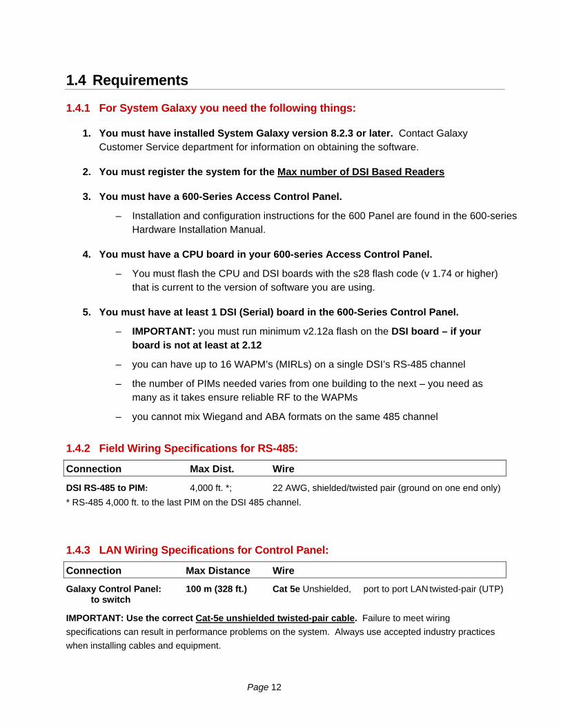
1.4.2 Field Wiring Specifications for RS-485:
Connection Max Dist. Wire
DSI RS-485 to PIM: 4,000 ft. *; 22 AWG, shielded/twisted pair (ground on one end only)
* RS-485 4,000 ft. to the last PIM on the DSI 485 channel.
1.4.3 LAN Wiring Specifications for Control Panel:
Connection Max Distance Wire
Galaxy Control Panel: 100 m (328 ft.) Cat 5e Unshielded, port to port LAN twisted-pair (UTP) to switch
IMPORTANT: Use the correct Cat-5e unshielded twisted-pair cable. Failure to meet wiring
specifications can result in performance problems on the system. Always use accepted industry practices
when installing cables and equipment.
Page 12

1.4.4 To install the PIM & WAPMs you need the following things:
NOTICE: This manual does not supersede the manufacturer’s instructions. Consult your Schlage
product manuals for instructions and requirements about installation, location and operation of devices.
1. a Pre-Installation Test Kit is available:
a. to test for reliable RF signals between the PIM and WAPMs
b. to determine where the PIM(s) will be located
c. to determine how many PIMs you need
2. a PC with a com port available to configure the PIMs and WAPMs.
3. Standard (null-modem) RS-232 Serial Cable to connect the PIM to the com port of the PC running the CDT software.
Male 9-pin D-shell on one end ~ female 9-pin D-shell on one end.
PIM SERIAL PORT CABLE PIN OUT DESCRIPTION
PIN 2 to 2 TD Transmit Data
PIN 3 to 3 RD Receive Data J5
PIN 5 to 5 Signal Ground
IMPORTANT: do not connect the RS-232 serial cable to the PIM while the RS-485 port is connected to the access control panel DSI 485 Channel.
4. Microsoft® Java msjavx86.exe installed on your PC in order to operate the CDT software. This is found on the Galaxy Install CD (Disc 2) in the Schlage folder at the root of the CD.
5. Microsoft® IE 6.0 (or later) browser to run the CDT software.
NOTICE: The Internet Explorer configuration interactive option for Sun Java must be unchecked and the option for Microsoft Java must be checked.
6. the CDT v1.7 (Configuration Demo Tool) software from Schlage in order to program the WAPM devices/doors. This installs on the C-drive in a typical directory path c > Program Files > WirelessDemoTool > WyrelessDemo.html. This tool is found on the Galaxy Install CD (Disc 2) in the Schlage folder at the root of the CD.
Page 13
1.5 Getting Started
Before you can configure the PIM you must:
– determine the location of the PIM (multiple PIMs may be needed to get reliable RF coverage).
– you must have met the requirements in Chapter 1 Section 1.4. of this document.
1.5.1 About determining the best mounting location for the PIM
You must consult the manufacturer’s documentation that matches your wireless products (PIM and WAPMs) for proper location guidelines.
A Schlage Pre-installation Test Kit and Portable WAPM are available to be used for determining PIM location to achieve proper RF communication.
1.5.2 About determining the location of the 600-series Panel
Chapter 1 of the 600-Series Hardware Installation Guide lists the installation and wiring requirements in detail. The Hardware Guide is found on the Galaxy Install CD (disc2) and on our website at www.galaxysys.com under technical support page (dealer login required).
The 600-series control panel must be with 4,000 ft of the last PIM on the 485 channel.
You may need to consider certain factors about location of the panel that concern your access control system as well. For example the panel must be wall mounted, is non-condensable, uses IP communicaitons to connect to its GCS Event Server.
If you are triggering outputs from door events/alarms, then you can also install the Digital I/O(DIO) board in the same panel.
You need to factor in wiring distances to all devices (i.e. PIMs, outputs, etc.) and LAN cable distances from the access control panel to the IP port, switch or router.
Page 14

1.6 Installing is the Configuration Demo Tool (CDT)
The CDT is a software tool that is used to …
– program the Schlage PIM (panel interface module) – link the PIM to the Wireless Access Point Modules (WAPMs) – test/troubleshoot the PIM to WAPM communications
You must install CDT v1.57 or later, along with Microsoft Java and Internet Explorer 6.0 or later.
NOTICE: The Internet Explorer configuration interactive option for Sun Java must be unchecked and the option for Microsoft Java must be checked.
Figure 4 – Screen shot of the Schlage Configuration Tool (CDT)
Page 15
2 Configuring the PIM/WAPMs using the CDT
This section covers setting up the PIMs and WAPMs using the Schlage CDT tool.
2.1 Connecting the PIM to the CDT
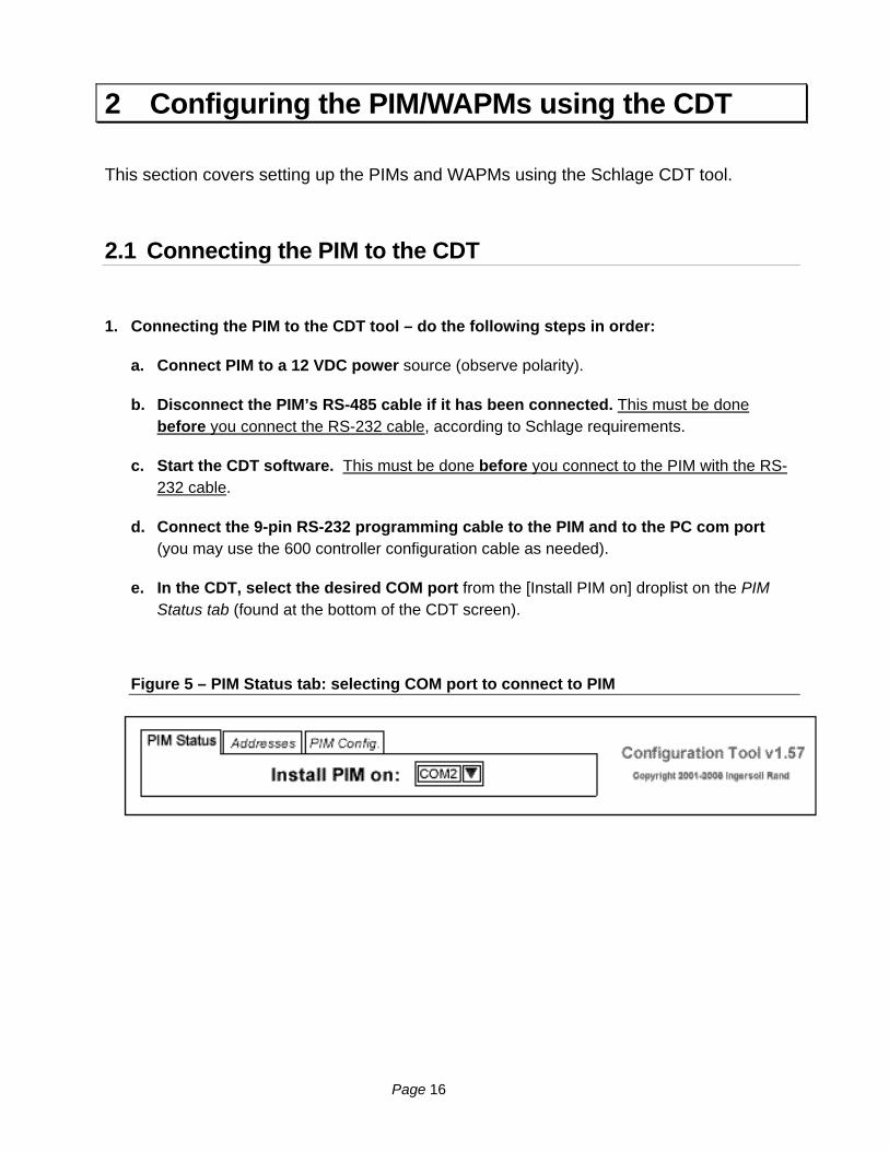
1. Connecting the PIM to the CDT tool – do the following steps in order:
a. Connect PIM to a 12 VDC power source (observe polarity).
b. Disconnect the PIM’s RS-485 cable if it has been connected. This must be done before you connect the RS-232 cable, according to Schlage requirements.
c. Start the CDT software. This must be done before you connect to the PIM with the RS-232 cable.
d. Connect the 9-pin RS-232 programming cable to the PIM and to the PC com port (you may use the 600 controller configuration cable as needed).
e. In the CDT, select the desired COM port from the [Install PIM on] droplist on the PIM Status tab (found at the bottom of the CDT screen).
Figure 5 – PIM Status tab: selecting COM port to connect to PIM
Page 16

2.2 Getting the PIM in Link Mode with the CDT tool
2. Put the PIM in Link Mode (or CDT Mode):
a. On the PIM, press and hold down the SA switch
b. While you are holding the SA switch, press & release the Reset switch
c. Continue holding the SA switch (about 20 seconds) until you see the CR-7 and CR-10 LED’s blinking rapidly. Note that the LEDs will blink slowly while you are holding the SA button. You must continue holding the SA button until the LEDs are blinking very rapidly.
d. You should see the message “Recognition PIM Connected on COM #” on the CDT Status tab (Fig. 6) when successful.
You have put the PIM in the Link Mode (or CDT mode) when you see this message. If you don’t get it right the first time, simply re-perform step-6.
NOTE: if the configuration fields in the CDT tool are grayed out and disabled, you need to restart the CDT software (see step 3/4).
NOTE: Once the connection to PIM is completed, a Link tab will display on the CDT screen.
Figure 6 – PIM Status tab: Connection Recognition for COM port to PIM
Page 17

2.3 Setting the PIM Address & Address Range for WAPMs
3. Select the Addresses tab. Remember the System Galaxy supports 16 max. WAPMs on a single DSI RS-485 channel/port.
– Setting the Unique field: this field is factory set to a random value. You may need to change the value to a number that is not already used by another PIM on this RS-485 channel/port. You cannot have a duplicate PIM Unique number.
Setting the Address LO and HI Ranges the PIM will control. The Reader Address Range supported by Galaxy’s DSI is 1 through 16.
– Set the LO Address to the lowest WAPM ID that this PIM will control (i.e. 1-16). Ex: If this is the first PIM on the 485 channel, you would set WAPM # 1 in this field. Otherwise you will set it to the next number after the HI Address on the previous PIM. See Fig. 2 in Chapter 1 for examples of splitting WAPMs among PIMs.
– Set the Hi Address to the highest WAPM ID that this PIM will control (1-16).
The Hi Address cannot be less than the Lo Address – thus it must be equal to or greater than the Lo Address ( Addr Hi >= Address Lo). If only one WAPM is on the PIM then the Hi address can be equal to the Lo address.
DO NOT duplicate or overlap numbers when setting LO & HI Addresses. See Fig. 3 in Chapt. 1 for examples of valid and invalid numbering.
– Set the PIM Address to a unique value not already used on this 485 Channel/port.
– Click [Set] button to send this information to the PIM.
Figure 7 – Addresses tab: Setting Addresses for the PIM
Page 18

2.4 Initiating the WAPM Link to the PIM
4. Select the Link tab. The status of the Link from the PIM to WAPM displays (Linking, Not Linking).
NOTE: The term ‘panel’ in this screen refers to the WAPM ID.
– Set the Panel Number (for WAPM/door) to a unique number not already used on this PIM or elsewhere on this 485 channel. The value you set here is the door reader ID in System Galaxy.
This number must be between 1 and 16 and must be unique and in sequence on this PIM and cannot be used again on the same RS-485 channel of the DSI board.
– Click the [ Start ] button. A linking session will begin. (Note: clicking the STOP button takes the PIM out of Link mode.)
Figure 8 – Link tab: Setting the WAPM ‘Panel’ Number
Page 19

2.5 Linking the WAPM to the PIM
5. Link your WAPM/Reader to the PIM: (see fig. 9)
You must perform specific steps at the WAPM/reader to establish a link between the PIM and WAPM. This may vary from on reader to another. The following steps were taken from the Schlage W.A.S. Manual P/N M053-007-B – see your manufacture’s instructions for the PIM and WAPM you are using.
NOTE: only one WAPM can be linked at a time.
NOTE: The battery pack must be installed in the MIRL.
NOTE: a portable WAPM must be opened and the reset switch pressed to link to the PIM (used for check points or muster points).
a. The PIM must be in the Link Mode (i.e. see step 6 of this document). Or refer to part 2.4 of the Schlage W.A.S. manual P/N M053-007-B. This is also known as CDT Mode and is when the COM connection recognized. If you have lost connection with the PIM the CDT fields will be grayed/disabled. Connect the serial cable and restart the CDT if necessary to restore connection.
b. Start linking process by opening the door ( this separates the door contact).
c. Hold down the Exit Lever (door handle) to create a Request to Exit (REX) – see Fig. 9.
d. While holding down the lever, present a card to the reader and wait for the MIRL LEDs to start blinking (approximately 8 seconds).
e. Release the lever and close the door.
During the linking process, the PIM’s LEDS (CR6 or CR9) and the MIRL LED will blink green for about 20 seconds while the RF signal integrity is being checked.
If the RF signal is good the PIM LED will turn solid and the MIRL blinks green and will beep the number of times as the channel number selected.
If the RF signal is not good, then the MIRL blinks red and beeps rapidly. The Schlage W.A.S. manual P/N M053-007-B Table 4.1 lists the meanings of the beeps and LED signals, and recommends you move the PIM or change the RF channel and retry the linking process.
The diagrams (Fig. 9) on next page are an example of a WAPM reader door hardware configuration.
Page 20
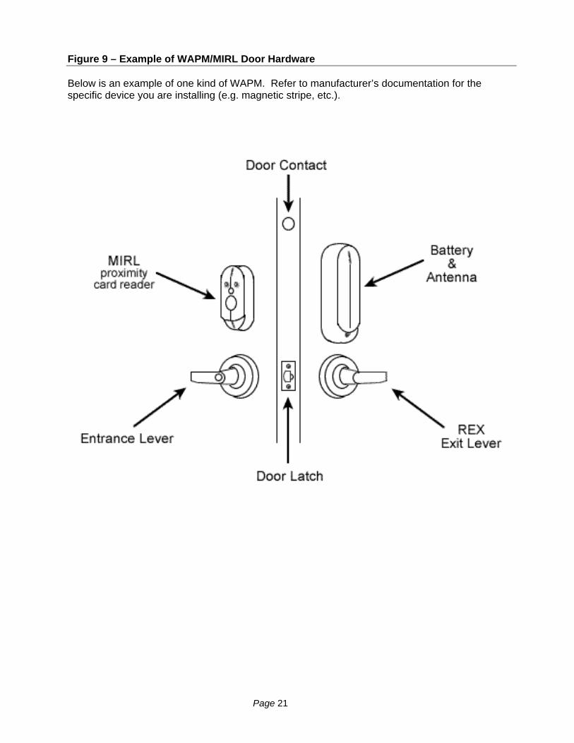
Figure 9 – Example of WAPM/MIRL Door Hardware
Below is an example of one kind of WAPM. Refer to manufacturer’s documentation for the specific device you are installing (e.g. magnetic stripe, etc.).
Page 21

2.6 Testing WAPM (door) with the CDT
6. Test the WAPM (door/reader) by presenting the correct card type (i.e. prox., mag stripe, etc.).
a. Select the door from the list.
b. Grant Access field: Checking this should allow the card to work as a valid card and door should unlock/open. Un-checking this field should cause the card to be denied and door should remain locked and should not open.
This test shows that the door and WAPM are communicating to the PIM and able to correctly read cards and grant access. You can use this process to isolate issues with communications to the WAPM when troubleshooting field issues.
Figure 10 – Status tab: Testing the door/reader
2.7 The Activity Log in the CDT
7. The Activity tab will display a log of events from your tests.
Figure 11 – Activity tab: Example of the Activity Log
The CDT tool will display a log of activity /events for the door/reader events.
Page 22

2.8 Configuring the WAPM (door access point) with the CDT
8. Getting the WAPM Configuration:
a. Select the Configuration tab.
b. Click the [Get] button near the bottom of the tab. NOTE: the PIM must be in CDT mode (step 6) and must be linked to the RF WAPM door access point (step 8 and 9).
Figure 12 – Configuration tab: Getting WAPM Configuration
Once the PIM gets the WAPM status, the fields populate with the settings of the WAPM.
Page 23

2.9 Setting the WAPM Heartbeat
9. Setting the WAPM Heartbeat (hh:mm:ss): this value controls how often the WAPM will poll the PIM for instructions when there is no activity (i.e. no card swipe, or REX, etc). Galaxy does not recommend that you set this value too low to avoid using up your batteries too fast.
– The default value = 10 minutes (approx. 4 years battery life or 60,000 card swipes).
– The lowest value = 15 seconds (with less than 1 year battery life). YOU MUST CLICK THE SET BUTTON TO SEND THIS DATA TO THE PIM. You can click the set button now or after you finish configuring the remaining settings.
Figure 13 – Configuration tab: Setting the WAPM Heartbeat
NOTE - Access Rules / Door Schedules: Cardholders, access rules, schedules and holidays are created in the SG software and loaded to the 600-series panel where they are stored in memory.
– Cardholders and Access Rules: When a card is swiped at the WAPM, an access request goes to the PIM and then to the SG 600-series controller. The control panel returns the appropriate response to the PIM for that card (granted or denied) based on whether that card has permission to use that door at that time, or not. The controller logs the card swipe and the permission (granted or denied) to the SG software and database. The PIM then stores the command until the WAPM picks it up (see setting the First, Delay and Retry values in Sect 2.10) .
– Schedules and Holidays: At the top of the minute of a scheduled time, the control panel sends the lock or unlock command to the PIM and logs the event to the SG software / database. The PIM / stores the command until the WAPM picks it up.
Therefore, if your WAPM heartbeat is 10 minutes and your unlock schedule is 8:00 AM, / your door should unlock after 8 AM, but before 8:10 AM - or sooner if a card is swiped.
– SG Operator manual commands: When the operator sends lock and unlock commands to the door, the controller forwards them to the PIM where they wait to be picked up by the WAPM.
Page 24
2.10 Setting the card swipe First, Delay and Retry timers
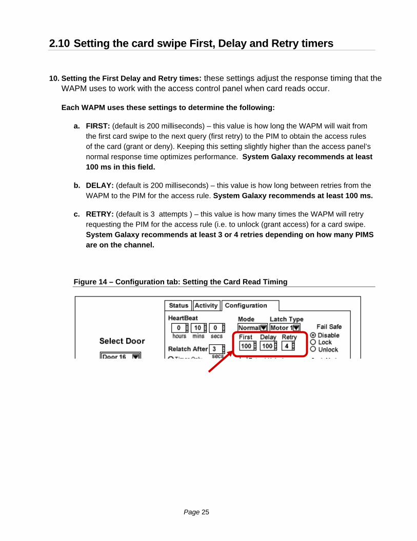
10. Setting the First Delay and Retry times: these settings adjust the response timing that the WAPM uses to work with the access control panel when card reads occur.
Each WAPM uses these settings to determine the following:
a. FIRST: (default is 200 milliseconds) – this value is how long the WAPM will wait from the first card swipe to the next query (first retry) to the PIM to obtain the access rules of the card (grant or deny). Keeping this setting slightly higher than the access panel’s normal response time optimizes performance. System Galaxy recommends at least 100 ms in this field.
b. DELAY: (default is 200 milliseconds) – this value is how long between retries from the WAPM to the PIM for the access rule. System Galaxy recommends at least 100 ms.
c. RETRY: (default is 3 attempts ) – this value is how many times the WAPM will retry requesting the PIM for the access rule (i.e. to unlock (grant access) for a card swipe. System Galaxy recommends at least 3 or 4 retries depending on how many PIMS are on the channel.
Figure 14 – Configuration tab: Setting the Card Read Timing
Page 25
2.11 Setting the WAPM Re-Latch Time
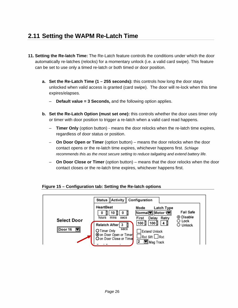
11. Setting the Re-latch Time: The Re-Latch feature controls the conditions under which the door automatically re-latches (relocks) for a momentary unlock (i.e. a valid card swipe). This feature can be set to use only a timed re-latch or both timed or door position.
a. Set the Re-Latch Time (1 – 255 seconds): this controls how long the door stays unlocked when valid access is granted (card swipe). The door will re-lock when this time expires/elapses.
– Default value = 3 Seconds, and the following option applies.
b. Set the Re-Latch Option (must set one): this controls whether the door uses timer only or timer with door position to trigger a re-latch when a valid card read happens.
– Timer Only (option button) - means the door relocks when the re-latch time expires, regardless of door status or position.
– On Door Open or Timer (option button) – means the door relocks when the door contact opens or the re-latch time expires, whichever happens first. Schlage
recommends this as the most secure setting to reduce tailgating and extend battery life.
– On Door Close or Timer (option button) – means that the door relocks when the door contact closes or the re-latch time expires, whichever happens first.
Figure 15 – Configuration tab: Setting the Re-latch options
Page 26

2.12 Setting Card Conversion
12. Setting the Card Conversion field : this field does not apply to System Galaxy therefore this field will be set to “NONE”.
Figure 16 – Configuration tab: Setting the Card Conversion
2.13 Setting the MODE
13. Setting the Mode field : this field must be set to “NORMAL” to interface with Galaxy.
Figure 17 – Configuration tab: Setting the Mode
Page 27

2.14 Setting the Latch Type
14. Setting the Latch Type field : this field must be set correctly.
a. Default = the factory setting based on lock or latch type issued with the access point.
Motor 1 – WEXK & Best Cylindrical IRL
Motor 2 - Best Mortise IRL & MIRL
Motor 3 - Saflok Mortise MIRL
Motor 4 – WA5600 Series, WA993 & Marks Cylindrical MIRL
Motor 5 – WA5200 Series
Figure 18 – Configuration tab: Setting the Latch Type
Page 28
2.15 Setting the Extended Unlock option
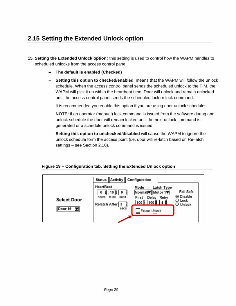
15. Setting the Extended Unlock option: this setting is used to control how the WAPM handles to scheduled unlocks from the access control panel.
– The default is enabled (Checked)
– Setting this option to checked/enabled means that the WAPM will follow the unlock schedule. When the access control panel sends the scheduled unlock to the PIM, the WAPM will pick it up within the heartbeat time. Door will unlock and remain unlocked until the access control panel sends the scheduled lock or lock command.
It is recommended you enable this option if you are using door unlock schedules.
NOTE: if an operator (manual) lock command is issued from the software during and unlock schedule the door will remain locked until the next unlock command is generated or a schedule unlock command is issued.
– Setting this option to unchecked/disabled will cause the WAPM to ignore the unlock schedule form the access point (i.e. door will re-latch based on Re-latch settings – see Section 2.10).
Figure 19 – Configuration tab: Setting the Extended Unlock option
Page 29

2.16 Setting the RXT (request to exit) option
16. Setting the RXT option: this setting determines whether the WAPM queries for unlock authorization on a Request to Exit activation (Exit Lever is down).
– The default is disabled (unchecked)
– Setting this option to unchecked/disabled means that the WAPM will only report that a request to exit has occurred. Schlage suggests to use this setting if the access point does not need to be electronically unlocked in order to provide egress (for instance, the access point has a crash bar) but the access control panel needs to be notified so that a forced door does not occur. System Galaxy uses unchecked.
– If Rxt is checked (enabled), then the WAPM will report that a request to exit has occurred and will query the PIM to determine if the access point should be electronically unlocked. Use this mode if the access point needs to be electronically unlocked in order to provide egress.
Figure 20 – Configuration tab: Setting the RXT (request to exit) option
Page 30

2.17 Setting the RXT SIFT option
17. Setting the RXT SIFT option: Determines whether WA56XX and WA993 reports Request to Exit events during unlocked state.
– If Rxt Sift is not checked (disabled), the WA5600 or WA993 will always report a request to exit has occurred regardless of the lock state.
– If Rxt Sift is checked (enabled), then the WA5600 Lockset or WA993 Exit Trim will not report a request to exit has occurred during the unit is unlocked. This is the default setting for the WA5600 Series and WA993.
SCHLAGE NOTICE: The Rxt Sift option can not be enabled for WA5200 Series Cylindrical Locksets or Wireless Reader Interfaces (WRIs) although the CDT may show the feature enabled. These units always report requests to exit no matter the setting of Rxt Sift or lock status.
Figure 21 – Configuration tab: Setting the RXT SIFT option
Page 31

2.18 Setting the MAG Track option
18. Setting the MAG Track option: This controls which track data is read from the Mag Stripe Card and is sent to the PIM-TD2 or PIM-485 from the WA Series or WPR access point module.
– 1 = track 1
– 2 = track 2 (Default)
– 3 = track 3
Figure 22 – Configuration tab: Setting the MAG Track option
Page 32
2.19 Setting the Fail Safe Options
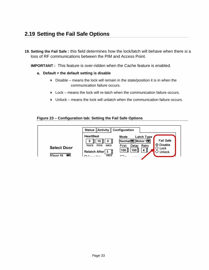
19. Setting the Fail Safe : this field determines how the lock/latch will behave when there si a loss of RF communications between the PIM and Access Point.
IMPORTANT : This feature is over-ridden when the Cache feature is enabled.
a. Default = the default setting is disable
Disable – means the lock will remain in the state/position it is in when the communication failure occurs.
Lock – means the lock will re-latch when the communication failure occurs.
Unlock – means the lock will unlatch when the communication failure occurs.
Figure 23 – Configuration tab: Setting the Fail Safe Options
Page 33
2.20 Setting the Cache Mode options
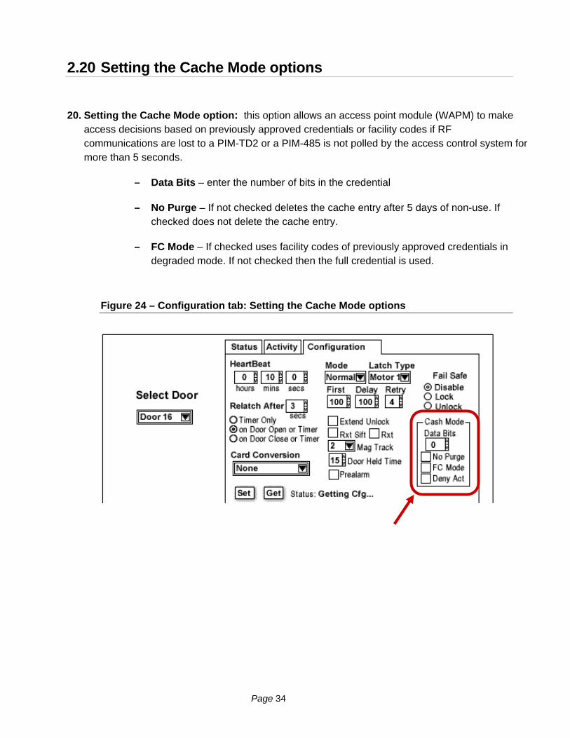
20. Setting the Cache Mode option: this option allows an access point module (WAPM) to make access decisions based on previously approved credentials or facility codes if RF communications are lost to a PIM-TD2 or a PIM-485 is not polled by the access control system for more than 5 seconds.
– Data Bits – enter the number of bits in the credential
– No Purge – If not checked deletes the cache entry after 5 days of non-use. If checked does not delete the cache entry.
– FC Mode – If checked uses facility codes of previously approved credentials in degraded mode. If not checked then the full credential is used.
Figure 24 – Configuration tab: Setting the Cache Mode options
Page 34

2.21 Setting the Pre-Alarm and Door Held options
Setting the Pre-Alarm and Door Held options: These options are related. Prealarm, if activated, provides a reader beeper 5 seconds prior to the PIM sending a door held open alarm. The number setting is the time to the door held open alarm transmission.
1. Defaults:
o Prealarm not active (unchecked) = beeper will not sound 5 seconds before the expiry of the door held timer.
Checking the Pre-alarm results in the battery powered WAPM sounding its beeper 5 seconds prior to the elapse of the door held open timer.
o Door Held alarm time – 15 seconds
o When the Door Held timer expires, the PIM sends a message to the access control system.
NOTICE: access control systems may not implement the door held open alarm report from the PIM and make its own decision on the door held open alarm.
NOTICE: System Galaxy is designed to determine door forced and door open too long alarms based on the state of the door (locked/unlocked) when the contact is separated, and how long the contact remains open. However the options are described below for your information.
Figure 25 – Configuration tab: Setting the Pre-Alarm and Door Held options
Page 35

Page 36
3 Configuring System Galaxy
This section provides a brief overview of how to set up System Galaxy hardware and software to integrate with the PIM-485 module.
3.1 About Installing the SG Software
Properly install the System Galaxy software, database & services on the communication and database servers. Note: On smaller systems, this can all be on one computer. On networked servers, the system can have the database installed on separate a database server.
Note: you will have a 14-day grace period to register your system from the day you install.
Software Reference Documentation:
The main System Galaxy Software Installation manual provides instructions about installing System Galaxy software. The Install CD also includes the install instructions on disk-1, which open in Internet Explorer (6.0 or later).
The main System Galaxy v8.2 Software manual covers information about configuring all the features and functionality of the SG software/system.
Also System Galaxy v8 PC Recommendations document covers the current recommendations and specifications for SG-8.
The Galaxy manuals are available in PDF format. Acrobat Reader 7.0 or later is recommended. You can find the manuals on the Software Install CD (disk-2).
You can also the manuals them on the Galaxy website (dealer login/password is required). To get a PDF manual from the website, go to www.galaxysys.com. Click on the Support link on the left side menu, then click Technical Support, then find the list of Documentation Links at the bottom of the Tech Support page.
Manuals are also available in print from customer service at Galaxy Control Systems.
Page 37
3.2 About Installing the 600-series Hardware
Properly install the Controller, the CPU board and DSI board according to the instructions in the 600 Hardware Manual.
You will need a null-modem cable to program the CPU: this cable should come with the controller panel (see requirements in Chapter 1 of this manual for cable specifications).
You will need a PC with a COM port and HyperTerminal: to configure the correct network parameters for the CPU and configure the board ID on the DSI.
A serial DSI board can have up to 16 doors on each RS-485 channel. There are two (2) RS-485 channels on a DSI board. Multiple PIM-485 units can be connected in a daisy-chain fashion to the DSI 485 channel. See Figure 25 on following page.
NOTE: you must install jumpers on the DSI port [ T – to R – ] and [ T + to R + ]
NOTE: you must install jumpers [ TB– to RB– ] and [ TB+ to RB+ ] on every PIM unit.
NOTE: you must ground the shielding on for every segment of RS-485 cable on one end. The following diagram shows shielding on the PIM end.
NOTE: The PIM unit should be powered on its own (separate) power supply.
The main 600-series Hardware Installation manual provides requirements and hardware installation instructions for the 600-series hardware, CPU and its daughter boards.
These step-by-step instructions cover installing and configuring the boards, flashing, and how to wire the field devices (readers, relays, inputs, outputs, etc.).
This manual is available in PDF format. Acrobat Reader 7.0 or later is recommended. You can find the manual on the Software Install CD (disk-2).
You can also the manuals them on the Galaxy website (dealer login/password is required). To get a PDF manual from the website, go to www.galaxysys.com. Click on the Support link on the left side menu, then click Technical Support, then find the list of Documentation Links at the bottom of the Tech Support page.
Manuals are also available in print from customer service at Galaxy Control Systems.
Page 38
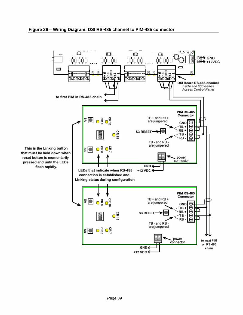
Figure 26 – Wiring Diagram: DSI RS-485 channel to PIM-485 connector
Page 39

3.3 Configuring the 600 Controller and DSI in the software
Once the 600 CPU is setup it will initiate an IP connection to the GCS Event Service on the Communication Server. The software must be programmed with the information about the Controller, DSI and Readers.
The following subsections describe configuring the System Galaxy software for Schlage Wireless readers. The main SG software manual describes the programming of cards, access rules, schedules, etc.
3.3.1 About Using System Galaxy software
The System Galaxy software and core GCS Services must be running in order to load programming to the controller or send door commands:
System Galaxy Software used to …
– program the 600 Loop/cluster and panel settings, add DSI board, configure the DSI channel for the PIM-485, etc.
– load card data, access rules, schedules/holidays, reader properties, etc.
– monitor doors / events, send door commands, etc.
GCS Client Gateway Service (systray icon looks like a PC monitor)
GCS Communication Service (systray icon looks like a yellow control panel)
GCS DBWriter Service (systray icon looks like a database symbol)
GCS Event Service (systray icon looks like a globe) this service specifically handles the 600-series Panel connections. The 600-series access control panels initiate their connections to this service.
3.3.2 Signing-in to the System Galaxy software
Start up System Galaxy software and log-on as a master operator:
a. Double-click the SG icon on the desktop of the Communication server
b. Supply the login name and password for a Master level operator
Figure 27 – Sign On/Off: Logging into System Galaxy
Page 40
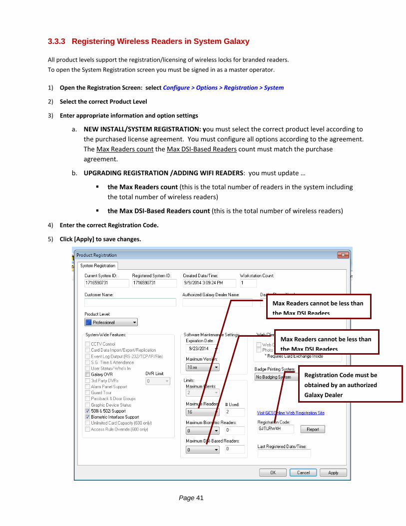
3.3.3 Registering Wireless Readers in System Galaxy
All product levels support the registration/licensing of wireless locks for branded readers.
To open the System Registration screen you must be signed in as a master operator.
1) Open the Registration Screen: select Configure > Options > Registration > System
2) Select the correct Product Level
3) Enter appropriate information and option settings
a. NEW INSTALL/SYSTEM REGISTRATION: you must select the correct product level according to
the purchased license agreement. You must configure all options according to the agreement.
The Max Readers count the Max DSI‐Based Readers count must match the purchase
agreement.
b. UPGRADING REGISTRATION /ADDING WIFI READERS: you must update …
the Max Readers count (this is the total number of readers in the system including
the total number of wireless readers)
the Max DSI‐Based Readers count (this is the total number of wireless readers)
4) Enter the correct Registration Code.
5) Click [Apply] to save changes.
Registration Code must be
obtained by an authorized
Galaxy Dealer
Max Readers cannot be less than
the Max DSI Readers
Max Readers cannot be less than
the Max DSI Readers
Page 41

3.3.4 Adding the Loop/Cluster in System Galaxy
Add the 600 Loop/cluster before adding the access control panel:
Click on the Loop button on the toolbar; {Or from the menu, select Configure > Hardware > Loops/Clusters.}
When the Loop Properties screen opens, click [ Add New ].
Type in a loop name.
Set Loop Type to “600”.
Set Connection Type to “TCP/IP”.
Enter the IP address of the Event Server (the PC running the GCS Event Service)
Remote Port should be “4003”
Enter the computer name of the Communication Server ( the PC running the GCS Communication Service). you can click the [ This Computer ] button if you are programming this on the communication server.
Click [ Apply ] to save settings.
Figure 28 – Loop/Cluster Properties: Configuring the Loop
Page 42
3.3.5 Adding the 600 Controller & DSI Board in System Galaxy
Add the 600 Controller (access control panel) to the loop/cluster:
Click on the Controller button on the toolbar, {Or from the menu, select Configure > Hardware > 600 Controller.}
When the Controller Properties screen opens, select the Loop/Cluster name you just created in the previous step.
click [ Add New ] to add the controller.
Enter the Controller serial number (found on the CPU board). This can be a valid serial number of any CPU in this loop/cluster.
Enter a user-friendly descriptive Name for the control panel. The software automatically assigns a controller name – you can / should change that to a name that logically describes the location or purpose of the panel (i.e. Lobby controller, or East Wing, 1st floor, etc.) for administration and future maintenance purposes.
Click the [Get Board Info] button: the Board Info screen will open and display the list of boards in that panel.
Click the [Save] button to add the boards. { OR you can add boards individually by clicking the [Add Board] button, setting the board # (you must know/match the board ID, choose the board type, and click [OK] }
Configure Alarm I/O Groups another Options as needed. You would only use alarm I/O options here if you were monitoring the controller alarm events.
Click [ Apply ] to save the configuration.
Page 43

Figure 29 – Controller Properties: Configuring the 600-series Controller
Page 44

3.3.6 Configuring the Serial Channels in System Galaxy
You must have added the DSI board in the controller property screen in order to be able to configure the
serial channels.
All the readers on a channel must be the same format (e.g. all Wiegand or all ABA). You cannot mix
reader technology. This means you cannot have both ABA and Wiegand on the same DSI port/channel.
Open the 600 Serial Channel Property screen from the SG menu bar selections Configure > Hardware > Serial Channel
Select the Cluster/Loop Name
Select the Controller Name
Select the appropriate DSI Board number / section number (e.g. Board 1; Sect 1) from the droplist.
Click Edit button
Set the Channel Mode: you can choose ‘Ingersoll Rand Wiegand’ or ‘Ingersoll Rand ABA’.
NOTE: setting a channel to ‘Unsused’ will disable the channel.
Check and/or uncheck the reader (WAPM) ID’s that you have attached to this DSI channel. If you have readers 1 through 8 installed, then you will check the first 8 WAPMs.
Click Apply to save changes.
NOTE: you may need to restart the Hardware Tree to see your readers. Do this by selecting View > Hardware Tree > from the menu.
You may edit the reader properties in the Reader Properties screen described in the next section.
Page 45
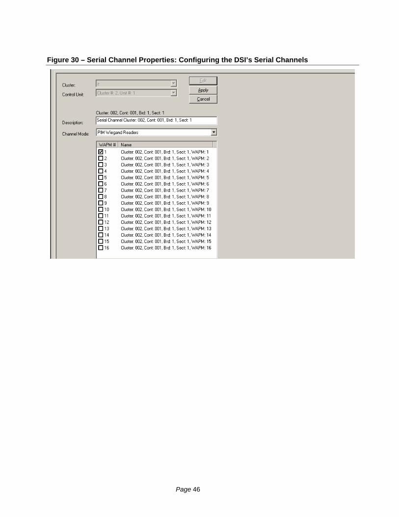
Figure 30 – Serial Channel Properties: Configuring the DSI’s Serial Channels
Page 46

3.4 Configuring the RF Reader Properties in System Galaxy
Some reader behaviors can be configured from System Galaxy. Some reader features must be set from the CDT tool. This section briefly covers the options that can be set from System Galaxy.
3.4.1 Setting Reader Properties from System Galaxy
To configure a Reader Port, open the Reader Port window. Follow the menu selections Configure > Hardware > Reader Ports, or click the Doors/Readers button on the toolbar.
When the Reader Port properties window opens, choose the loop that includes your controller. Use the Loop drop-down list to select a loop.
Then select the specific controller for your readers in the Controller drop-down list.
Select the specific reader port in the Reader Name drop-down list.
Click the Edit button. When Edit is clicked, the fields in the main area become enabled:
Enter a descriptive Reader Name (up to 65 characters) that makes the reader easy to identify (i.e. Room 101; supply closet).
The Reader Type field will be disabled, but it will display the format you assigned to this DSI channel when you configured the serial channels (Wiegand or ABA).
Figure 31 – Reader Properties: Configuring the Reader Name
Page 47
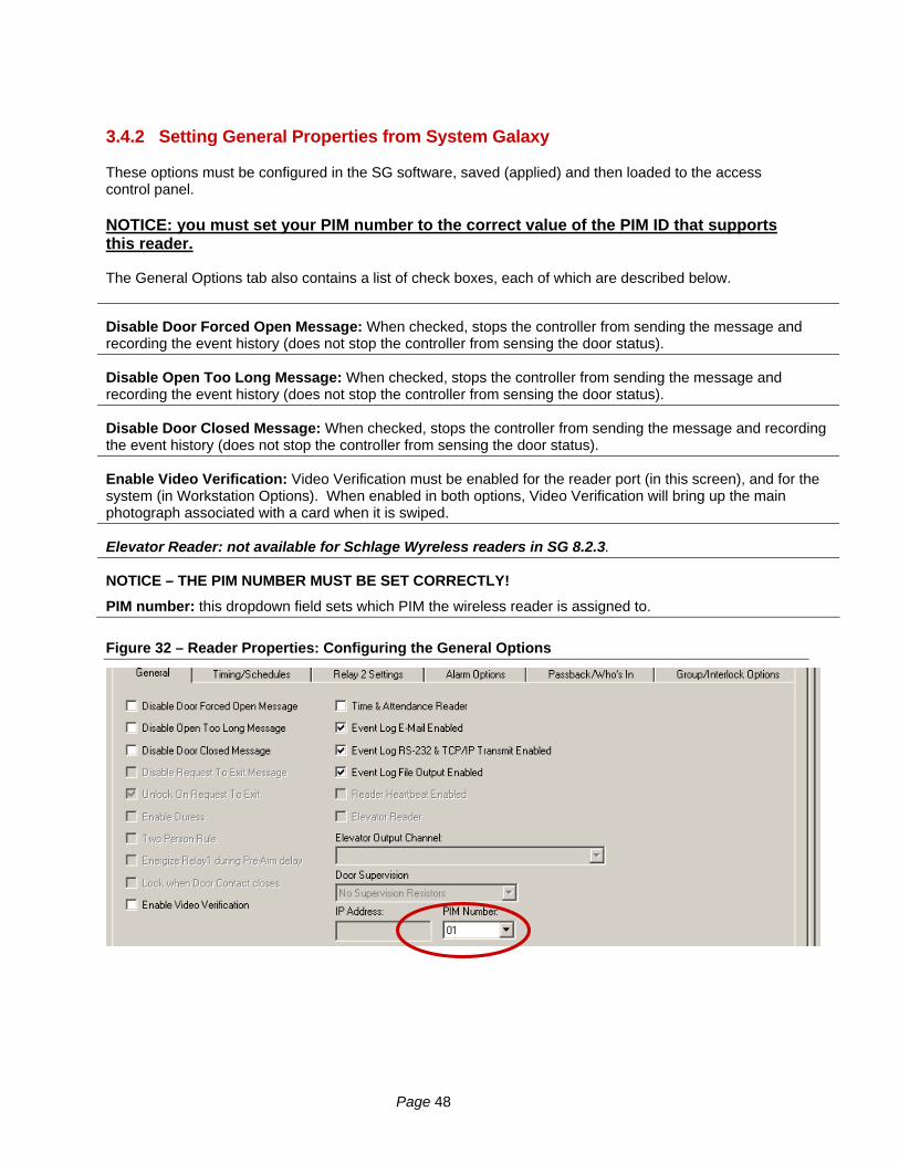
3.4.2 Setting General Properties from System Galaxy
These options must be configured in the SG software, saved (applied) and then loaded to the access control panel.
NOTICE: you must set your PIM number to the correct value of the PIM ID that supports this reader. The General Options tab also contains a list of check boxes, each of which are described below.
Disable Door Forced Open Message: When checked, stops the controller from sending the message and recording the event history (does not stop the controller from sensing the door status).
Disable Open Too Long Message: When checked, stops the controller from sending the message and recording the event history (does not stop the controller from sensing the door status).
Disable Door Closed Message: When checked, stops the controller from sending the message and recording the event history (does not stop the controller from sensing the door status).
Enable Video Verification: Video Verification must be enabled for the reader port (in this screen), and for the system (in Workstation Options). When enabled in both options, Video Verification will bring up the main photograph associated with a card when it is swiped.
Elevator Reader: not available for Schlage Wyreless readers in SG 8.2.3.
NOTICE – THE PIM NUMBER MUST BE SET CORRECTLY!
PIM number: this dropdown field sets which PIM the wireless reader is assigned to.
Figure 32 – Reader Properties: Configuring the General Options
Page 48
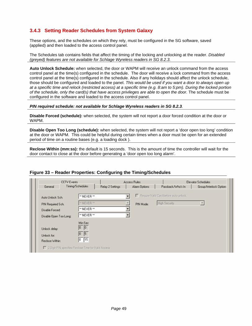
3.4.3 Setting Reader Schedules from System Galaxy
These options, and the schedules on which they rely, must be configured in the SG software, saved (applied) and then loaded to the access control panel. The Schedules tab contains fields that affect the timing of the locking and unlocking at the reader. Disabled (greyed) features are not available for Schlage Wyreless readers in SG 8.2.3.
Auto Unlock Schedule: when selected, the door or WAPM will receive an unlock command from the access control panel at the time(s) configured in the schedule. The door will receive a lock command from the access control panel at the time(s) configured in the schedule. Also if any holidays should affect the unlock schedule, those should be configured and loaded to the panel. This would be used if you want a door to always open up at a specific time and relock (restricted access) at a specific time (e.g. 8:am to 5:pm). During the locked portion of the schedule, only the card(s) that have access privileges are able to open the door. The schedule must be configured in the software and loaded to the access control panel.
PIN required schedule: not available for Schlage Wyreless readers in SG 8.2.3.
Disable Forced (schedule): when selected, the system will not report a door forced condition at the door or WAPM.
Disable Open Too Long (schedule): when selected, the system will not report a ‘door open too long’ condition at the door or WAPM. This could be helpful during certain times when a door must be open for an extended period of time on a routine bases (e.g. a loading dock ).
Reclose Within (mm:ss): the default is 15 seconds. This is the amount of time the controller will wait for the door contact to close at the door before generating a ‘door open too long alarm’.
Figure 33 – Reader Properties: Configuring the Timing/Schedules
Page 49

3.4.4 Setting Reader Alarm Options from System Galaxy
These options, and any I/O Groups on which they rely, must be configured in the SG software, saved (applied) and then loaded to the access control panel. You do not have to select an I/O group to be able to configure Alarm Options. Alarm Options are independent of I/O groups. System Galaxy allows controllers to generate alarms based on certain conditions at the door or reader.:
An alarm event is basically created when a specific is configured to generate an Alarm Message. An alarm event displays on the Alarm Event window in the order it occurs unless an alarm priority is configured. When an alarm priority is configured, the alarm messages will still appear when they occur but the order they display in the alarm window is sorted by the number assigned to the priority field. NOTICE: The Acknowledge check-box must be selected before Priority will apply. There are several conditions that can be configured with I/O groups and Alarm settings. Those conditions are Door Forced Open, Open Too Long, Invalid Attempt, Valid Access, and Passback Violation. I/O Groups: The drop-down list shows all the available I/O Groups. By default, the field is set to **NO I/O GROUP**. When an I/O Group is selected, that I/O group will be activated whenever the condition occurs on the reader. I/O groups are used to activate outputs associated with the alarm condition. I/O Offsets: This field contains the I/O Offsets for each condition. Acknowledge: Select (check) this checkbox if the condition should appear as an alarm event (in the alarm events window). Priority: The Acknowledge check-box must be selected before Priority will apply. The priority field is an optional numeric field that accepts a value equal or less than 9999. This is the priority level of that will be assigned to the alarm event. Priority affects the order of the alarm events in the Alarm Events window. Alarms with higher priority number are sorted to the top of the screen regardless of the order they occur. Instructions: The Acknowledge check-box must be selected before Instructions will apply. When this button is clicked, a window appears in which you can type in text instructions for responding to the alarm event. Audio: The Acknowledge check-box must be selected before Audio will apply. The location of files must also be set up in the Multimedia tab of the Workstation Options window (Configure > Options > Workstation Options > Multimedia tab). One .wav file can be selected to play when the alarm event occurs.
Figure 34 – Reader Properties: Configuring the Alarm Options
Page 50