SYSTEM FILE NO. 3020 CALC. TYPE ID IE CAROLINA POWER ...
58
SYSTEM FILE NO. 3020 CALC. TYPE ID IE PRIORITY 0 CAROLINA POWER & LIGHT COMPANY RNP-IIINST-1043 FOR MAIN STEAM PRESSURE UNCERTAINTY AND SCALING CALCULATION FOR H. B. ROBINSON UNIT 2 SAFETY RELATED : AUGMENTED QUALITY: NON SAFETY: YES NO El ED n 0 APPROVAL
Transcript of SYSTEM FILE NO. 3020 CALC. TYPE ID IE CAROLINA POWER ...

SYSTEM FILE NO. 3020CALC. TYPE ID IEPRIORITY 0
CAROLINA POWER & LIGHT COMPANY
RNP-IIINST-1043
FOR
MAIN STEAM PRESSURE UNCERTAINTY AND SCALING CALCULATION
FOR
H. B. ROBINSON UNIT 2
SAFETY RELATED :AUGMENTED QUALITY:NON SAFETY:
YES NOEl
EDn 0
APPROVAL

Computed By: Date- CAROLINA POWER & LIGHT COMPANY RNP-IIINST-1043
Checked By: Date: CALCULATION SHEET Pg. 1 of 45 Rev: 5
Project No.: File:
Project Title:
Calculation Title: Main Steam Pressure Uncertainty and Scaling Calculation
Tsnbl of CnntpntsSE DESCRUrFrQN PAGEF
REVISION HISTORY ............................................. 2
1.0 OBJECTIVE ............................................. 3
2.0 FUNCTIONAL DESCRIPTION ............................................. 3
3.0 LOOP DIAGRAM ............................................. 5
4.0 REFERENCES ............................................. 7
5.0 INPUTS AND ASSUMPTIONS ............................................. 9
6.0 CALCULATION OF UNCERTAINTY CONTRIBUTORS ............................................ 10
7.0 TOTAL LOOP UNCERTAINTY (FLU) .............................. : 26
8.0 DISCUSSION OF RESULTS ............................. 33
9.0 SCALING CALCULATIONS ............................. 40
tMXT OF ATTrACIMFNTS PAGF.E
A. Calculation Matrix Reference Table I
B. 00813-01004808, Rosemount Model 3051NG Smart Pressure Transmitter for Nuclear 1-3Servicc. Rev. DA, Dated August, 2001
C. Deleted
D. NUS Instruments Long Term Drift Test for NUS Modules - Final Report, Executive 1, 2Summary, dated October 26, 2001
E. Email from NUS Confirming Similarity of NUS Isolator Modules, dated 01/15/02 1,2
F. ComparatorHistorical Drift Study I
G. Indicator Specifications I

Computed By: Date: CAROLINA POWER & LIGHT COMPANY RNP-.IINST-1043
Checked By: Date: CALCULATION SHEET Pg. 2 of 45 |Rev: 5
Project No.: File:
Project Title:
Calculation Title: Main Steam Pressure Uncertainty and Scaling Calculation
RFVISTON HISTORY
FWCRTPTQION Q CHANG.P.HUFJ&ION
0 Initial issue of calculation.
I Correct As Left Tolerances and Hagan Room Temperature.
2 Add seismic effect uncertainty values to the transmitter Total Device Uncertainty(TDU) and revise impacted sections.
3 To correct errors, to include NUS module data, and place in standard format.
4 Revised to reflect transmitter replacement with more accurate model. Also removedconservatism in isolator uncertainty to support Power Uprate accuracy requirements.
5 Revised to correct typographical errors and to include the new values from thesteam header calculation.

Computed By: Date: CAROLINA POWER & LIGHT COMPANY Calculation ID0
Checked By: Date: CALCULATION SHEET Pg. 3 of 45 ]Rev: 5
Project No.: File:
Project Title:
Calculation Title: Main Steam Pressure Uncertainty and Scaling Calculation I
1.0 ORlECTIN'U
This calculation computes the loop uncertainties associated with the indication, alarm, andsafeguards actuation setpoints provided by the Main Steam Line Pressure instrumentation loops.The instrumentation also provides an input into the Emergency Response Facility InformationSystem (ERFIS). The uncertainties at the input to ERFIS are calculated. The uncertainty associatedwith the pressure input signal for safeguards actuation signal as a result of High Steam Flowcoincident with Low Main Steam Line Pressure is determined. The uncertainty associated withHigh Steam Line Differential Pressure is determined. This is used as an input to safeguardsactuation. The Reactor Turbine Generator Control Board (RTGB) indication uncertainty isdetermined. This calculation also determines the Allowable Value (AV) for the safeguardsinitiation setpoint.
Uncertainties associated with the control functions provided by Main Steam Line Pressure arc notcalculated.
The instrument loops contain the components in Section 3.0 and are addressed in this calculation.
2.0 FTTNC(TONAT. DESCRIP1TON
The Main Steam Line Pressure channels are used to provide indication of Main Steam LinePressure on the RTGB during normal and accident conditions, an input for Safeguards actuation,and Main Steam Flow density compensation.
The instrument loops that are the subject of this calculation provide the following functions:
* Safeguards actuation signal on High Steam Flow coincident with Low Main Steam LinePressure.
* Safeguards actuation signal on High Steam Line Differential Pressure.* Steam Flow density compensation.
2.1 NORMAL FINMON
Indication is displayed on PI-474, 475, 476, 484, 485, 486, 494, 495, and 496. An output of thisinstrument loop is used to compensate Main Steam Flow for density. These loops also provideinput to ERFIS.

Computed By: Date: CAROLINA POWER & LIGHT COMPANY Calculation ID:CAROINAPOWE & IGHTCOMANYRNP.IIINST-1043
Checked By: Date: CALCULATION SHEET Pg. 4 of 45 |Rev: 5
Project No.: File:
Project Title:
Calculation Title: Main Steam Pressure Uncertainty and Scaling Calculation
2.2 A CC-IDENT MITIGATIN( TF1 NMTON
Per Reference 4.7.7, the instrument loops addressed in this calculation produce an input to thesafeguards actuation system on steam flow mismatch and high steam flow coincident with lowsteam pressure or low Tqvg.
2 1i PICT AC(ClI.NJT MAN11Tf)RIN)W. VINtCTInNA._ - -- l- ...... - -
Per Reference 4.6.2 the transmitters and indication provide indication post accident. Per Reference4.6.2 the pressure transmitters are Reg. Guide 1.97 Al, B1, Cl, and D2 variables, therefore, theinstrument loops addressed in this calculation remain operable prior to and following a DesignBasis Accident.
2.4 POST SEIRMIC
Per Reference 4.7.7 the transmitters and indication provide indication post seismic.

Computed By: Date: CAROLINA POWER & LIGHT COMPANY RNPClcNuto I043
Checked By: Date: CALCULATION SHEET Pg. 5 of 45 |Rev: 5
Project No.: File:
Project Title:
Calculation Title: Main Steam Pressure Uncertainty and Scaling Calculation
3.0 lO(P UIAG.RAM
To Steam FlowISee Reference 4.2.6)
and
High Steam LineDifferential PressureSafeguards Actuation
From Steam HeaderPressureISee Reference 4.2.1)
Computed By: Date: CAROLINA POWER & LIGHT COMPANY RNPClcINST-1043
Checked By: Date: CALCULATION SHEET Pg. 6 of 45 | Rev: 5
Project No.: File:
Project Title:
Calculation Title: Main Steam Pressure Uncertainty and Scaling Calculation
Tag number Function Make and Model Location Reference
PIT-474, 475,476, Transmitter 305ING Turbine Building 4.7.4,4.7.6484,485,486,494,495,496
PQ474. 475, 476, Power Supply NUS SPS801 or Hagan Rack 4.1.1-5; 4.7.4484, 485,486, 494, Westinghouse495.496 4111085-001
PM474AIR, 475A/R I/V Westinghouse Hagan Rack 4.1.1-5; 4.7.4PM-476A/R, 485A/R 3110554-000PM-486A/R, 494AIRPM-495A/R, 496A/R
P-474, 475,476,484, Computer Westinghouse Hagan Rack 4.1.1-5; 4.7.4485,486,494,495, Signal 3110552-000496 Conditioner
PM-474D, 475C, Signal Isolator NUS EIP- Hagan Rack 4.1.1-5; 4.7.4476B, 484B, 485B, E013DD-1486B, 494D, 495C,496B
PM474A, 475A, Signal Isolator NUS OCA-800- Hagan Rack 4.1.1-5,4.7.4476A, 484A, 485A, 05-07-08486A, 494A, 495A,496A ___
PC-474A1R, 474B/R, IIV module Westinghouse Hagan Rack 4.1.1-5,4.7.4475/R, 476JR, 4841R, 3110554-000485A/R, 485BIR,486/R, 494/R, 495/R,496A/R, 496B/R
PC474A, 474B, Comparator Westinghouse Hagan Rack 4.1.1-5; 4.7.4475,476,484, 485A, 4111082-001 or485B, 486,494,495, NUS SAM 800496A, 496B or DAM 800
PI-474,475,476, Indicator International Control Room 4.1.1-5; 4.7.4484,485,486,494, Instruments495,496 2520VB_
Instrument identification
Computed By: Date: CAROLINA POWER & LIGHT COMPANY Calculation ID-RNP-l/INST.1 043
Checked By: Date: CALCULATION SHEET Pg. 7 of 45 Rev: 5
Project No.: File:
Project Title:
Calculation Title: Main Steam Pressure Uncertainty and Scaling Calculation
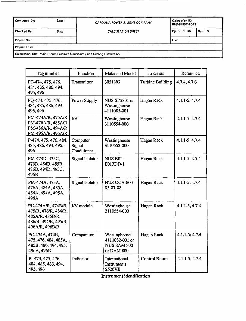
4.0 EEEREiNCFS
4.1 DRAWYINGS
4.1.1 5379-03488, Hagan Wiring Diagram, Revision 154.1.2 5379-03489, Hagan Wiring Diagram, Revision 164.1.3 5379-03490, Hagan Wiring Diagram, Revision 164.1.4 5379-03491, Hagan Wiring Diagram, Revision 194.1.5 5379-03492, Hagan Wiring Diagram, Revision 134.1.6 G-190184, General Arrangement Turbine Building Sections A-A and B-B,
Revision 104.1.7 G-190292, Turbine Building Mezzanine Floor Plan Instrumentation Arrg't,
Revision 84.1.8 HBR2-10618, Inservice Inspection Drawing Loop 1 - 26" Main Steam Line No.
26"-MS-1 CPL212, Revision 34.1.9 HBR2-11135 sheet 2, RTGB Panel C - Annunciator Section, Revision 1
4.2 CA l .CT L ,ATIONS
4.2.1 RNP-IIINST-1050, Steam Header Pressure Uncertainty and Scaling Calculation,Revision 3
4.2.2 RNP-E-1.005, 120 VAC Instrument Bus Voltage, Revision 24.2.3 RNP-M/MECH-1651, Containment Analysis Inputs, Revision 104.2.4 RNP-B/MECH-1388, Revision 0, Attachment C4.2.5 RNP-M/MECH-1741, 32-5015594-00, Appendix K Power Upratc Operating
Conditions, Revision 04.2.6 RNP-IIINST-1040, Steam Flow Uncertainty Scaling Calculation, Revision 3
4.3 REGY 11 ATORY )ClITMENVT
4.3.1 None
4.4 TECHNTCAL. MANI TAT S
4.4.1 728-589-13, VendorManual Hagan,Revision 224.4.2 728-399-88, Auxiliary Indicating Meters Bulletin Model 2500 2520,
Revision 2

Computed By: Date: CAROLINA POWER & LGHT COMPANY Calculation ID:
Checked By: Date: CALCULATION SHEET Pg. 8 of 45 Rev: 5
Project No.: File:
Project Title:
Calculation Title: Main Steam Pressure Uncertainty and Scaling Calculation
4.5 CAT.TRRATION nnd MAINTF.NAN(F. PROCl;rl)I1RRF1
4.5.1 LP-901, Steam Generator Pressure Channel 474 Loop #1 Channel #2,Revision 6
4.5.2 LP-902, Steam Generator Pressure Channel 475 Loop #1 Channel #3,Revision 5
4.5.3 LP-903, Steam Generator Pressure Channel 476 Loop #1 Channel #4,Revision 5
4.5.4 LP-904, Steam Generator Pressure Channel 484 Loop #2 Channel #2,Revision 4
4.5.5 LP-905, Steam Generator Pressure Channel 485 Loop #2 Channel # 3,Revision 5
4.5.6 LP-906, Steam Generator Pressure Channel 486 Loop #2 Channel # 4,Revision 5
4.5.7 LP-907, Steam Generator Pressure Channel 494 Loop #3 Channel # 2,Revision 5
4.5.8 LP-908, Steam Generator Pressure Channel 495 Loop #3 Channel # 3,Revision 5
4.5.9 LP-909, Steam Generator Pressure Channel 496 Loop #3 Channel # 4,Revision 5
4.5.10 PIC-845, Rosemount Smart Transmitters, Revision 04.5.11 MMM-006, Appendix B-3, Calibration Data Sheets, Revision 04.5.12 MMM-006, Calibration Program, Revision 22
4.6 PROCF.ITHRF'S
4.6.1 EGR-NGGC-0153, Engineering Instrument Setpoints, Revision 94.6.2 TMM-026, List of Regulatory Guide 1.97 Instruments, Revision 18
4.7 OThER RFIEPFNCM
4.7.1 UpdatedFinal Safety Analysis Report4.7.2 Technical Specifications4.7.3 RNP-F/NFSA-0045, RNP Cycle 21 Reload Plant Parameters Document,
Revision 24.7.4 Equipment Data Base (EDB)

Computed By: Date: CAROLINA POWER C LIGHT COMPANY alculation ID:CAROINAPOWE & IGHTCOMANYRNP-IIINST-1043
Checked By: Date: CALCULATION SHEET Pg. 9 of 45 Rev: 5
Project No.: File:
Project Title:
Calculation Title: Main Steam Pressure Uncertainty and Scaling Calculation
4.7.5 R82-226/01, DBD for Control Room Habitability Modifications 993 & 994Revision 6
4.7.6 EC 47152 R04.7.7 DBD/R87038/SD06, DBD for the Reactor and Safeguards Protection System,
Revision 54.7.8 ASME Steam Tables, 6 h Edition
5.0 INPIITS AND ASSI1M"TIONS
5.1 The accuracy of a typical test resistor is on the order of ± 0.01%. Therefore, the testresistors used during calibration are assumed to have a negligible impact on the overalluncertainty calculation.
5.2 Per Reference 4.7.5, the ambient temperature in the Control Room varies from 70cF to77V during operation. The calibration temperature for the indicator is assumed to be600F. Therefore, a change in temperature of 170F (9.4"C) is used to compute the indicatortemperature effect.
5.3 Per Reference 4.7.4, the pressure transmitters are located in the Turbine Building. TheTurbine Building is an open structure. Because the transmitters are located inthermostatically controlled enclosures, the minimum temperature used to compute thetransmitter temperature effect is assumed to be 33 TF. The maximum temperature is107'F. (Reference 4.7.1 provides the information and references the U.S. Department ofCommerce, Environmental Data Service, "Climatic Atlas of the United States" June1968 as a source).
5.4 Per Reference 4.6.1, reference accuracy typically includes the effects of linearity,hysteresis, and repeatability. The indicator reference accuracy is given in Reference 4.4.2is assumed to include the effects of linearity, hysteresis, and repeatability.
5.5 Per Reference 4.7.5, the maximum temperature of the Hagan Room is 820F. PerReference 4.6.1, the racks may experience an additional 100F heat rise during operation.The ambient temperature at the time of calibration is assumed to be 500F. Therefore, achange in temperature of 420F is used to compute the temperature effect associated withthe rack components.
(820F+100F)-50OF = 420F

Computed By: Date: CAROLINA POWER & LIGHT COMPANY RNP-CuINST-1043
Checked By: Date: CALCULATION SHEET Pg. 10 of 45 1Rev: 5
Project No.: File: l
Project Title:
Calculation Title: Main Steam Pressure Uncertainty and Scaling Calculation
5.6 The Westinghouse 3110552-000 Computer Signal Conditioner is a high precisionresistor. Based on the high accuracy of the resistor, the resistor has a negligible impacton the overall loop uncertainty computation.
5.7 Per References 4.5.1 through 4.5.9, the IN module is calibrated as part of a string. PerReference 4.4.1, the IN module is a resistor. Resistors typically experience negligibledrift. Therefore, any resistor drift throughout the fuel cycle is negligible and is accountedfor during the string calibration.
5.8 The transmitters are seismically qualified by Rosemount. Per Attachment B, the postseismic effect of the transmitter is ± 0.25% of Span.
5.9 As noted on the Instrument Identification Table in Section 3.0, there are two types ofNUS isolators used in the instrument loops addressed by this calculation. Theperformance specifications of these similar devices are almost identical, but they containminor differences. To facilitate this calculation, the isolators are considered to be thesame and, in every case, the more conservative of specific device uncertainty terms isused to determine overall device uncertainty for the isolators.
5.lOThe temperature of the pure water used to calibrate the transmitters is assumed to be900F.
5.11 The process pressure at 6% Steam Generator Tube Plugging is used. This value isobtained from Reference 4.2.5.
6.0 CAMI ,T .ATION OF I TNrFRTA NT-Y CONTRIRI STOR
6.1 A CCI)FNT EFFECTS (A En
Per References 4.6.2 and 4.7.7, the indication functions provided by each loop are requiredto function post accident.
6.1.1 Acnident Ti-niprethire Effrct (ATE)
The pressure transmitters are located in the Turbine Building. They are not subject to anadverse or temperature higher than normal ambient by any accident. Therefore, theAccident Temperature Effect (ATE) is not included.
ATE = 0.0% Span

Computed By: Date: Calculation ID:
CAROLINA POWER & LIGHT COMPANY RNP-IfINST-1043
Checked By: Date: CALCULATION SHEET Pg. 11 of 45 Rev: 5
Project No.: File:
Project Title:
Calculation Title: Main Steam Pressure Uncertainty and Scaling Calculation
6.1.2 Accidrent Er"' sure EfMect (APFR
The pressure transmitters are not exposed to a pressure above normal atmospheric during anyaccident analyzed in Reference 4.7.1. Therefore,
APE = 0.0% Span
6.1.3 Acridlent R-ndfition Effect (ARF')
The pressure transmitters are located in the Turbine Building and are not subject to areas ofhigh or abnormal radiation levels. Therefore,
ARE = 0.0% Span
Accident Effect is calculated using the following equation:
AE = APE+ JATE2 + ARE'
AE = 0.0% Span
6.2 SEISMIC EFFECT (.9F)
Per Reference 4.7.7, the instrumentation must function prior to and following a seismic event.The impact of a seismic event is a random variable and will be considered in determining theTotal Loop Uncertainty (TLU) associated with the instruments.
6.3 INSIIU.ATION RF..STANC-rF ERROR (TR)
The instrument loops addressed in this calculation are not required to mitigate any event thatresults in degraded signal cabling. Therefore, Insulation Resistance (IR) effects are notapplicable.
i

Computed By: Date: CAROLINA POWER & LIGHT COMPANY RNPCIcINST 1043
Checked By: Date: CALCULATION SHEET Pg. 12 of 45 Rev: 5
Project No.: File:
Project Title:
Calculation Title: Main Steam Pressure Uncertainty and Scaling Calculation
6A PROCESS MEASNTREFNT ERROR (PMF)
.3encing T ine Density Efferts
Per Section 9.1 of this calculation, the transmitter is located 20.03 fcct below thecondensate pot. A sensing line fill fluid of pure water at 900F per Section 5.10 and aprocess pressure of 800.5 psia per Reference 4.2.5 is used to calculate the hydrostatic headon the transmitter. Per Input and Assumption 5.3 the maximum ambient temperature is1070F. The sensing lines are insulated against freezing and the transmitters are enclosed ina temperature controlled housing. Therefore the minimum temperature is 33 0F. Theprocess measurement effect due to changes in sensing line fill fluid density (PME) is a onedirectional bias calculated with the following equation:
(h(PN-pc)Y 100%SpannorPME = I I
144 1400 )where,
h = height of sensing line= 20.03 feet
pN@107 = sensing line fill fluid density during normal operation= 62.05338 Ibm/ft3 @ 107 0F, 800.5 psia
PN@33 =sensing line fill fluid density during normal operation= 62.58826 Ibm/ft3 @ 330 F, 800.5 psia
pc@vo = sensing line fill fluid density used for scaling= 62.26799 Ibm/ft3 @ 90F, 800.5 psia
NOTE: The factor 144 is used to convert from lbf/ft' to lbf/in'. At standardgravity, Ibm may be replaced with Wbf.
Using the equation stated above for PME yields the following events:
norPME = +0.0032/-0.0021 % Span
Per Reference 4.6.1, uncertainty terms with a magnitude of 5 0.05% Span will have anegligible effect the calculation, and may be omitted. Therefore,
norPME = 0.0% Span

Computed By: Date: CAROLINA POWER & LIGHT COMPANY Calculation ID:CAROINAPOWE & IGHTCOMANYRNP-I/INST.1043
Checked By: Date: CALCULATION SHEET Pg. 13 of 45 1Rev: 5
Project No.: File:
Project Title:
Calculation Title: Main Steam Pressure Uncertainty and Scaling Calculation
6.5 PRIMARY ElEMENT ERROR (PFE
There is not an element associated with the measurement of Main Steam Line Pressure.Therefore,
PE = 0.0% Span
6.6 TRANSMITTER
6.6.1 Trlngmittjrf s I fnivrifiedu Atfrihuide of Reference Acevirncy (RAx,#
Per Attachment B, the Reference Accuracy for transmitters with a Range Down Factor of1:1 to 10:1 (RDF = URL / Calibrated Span) is ± 0.075% Span, and includes the effects oflinearity, hysteresis, and repeatability. The maximum span is 2000 psig and the calibratedspan is 1400 psig, so the RDF for this application is 1.43. Per Reference 4.7.6, thetransmitter is calibrated to + 0.20% Span. Per Reference 4.7.6, the transmitters arecalibrated at 9 cardinal points (5 up and 4 down). Therefore, the calibration procedureverifies the attributes of linearity and hysteresis but not repeatability. Per Reference 4.6.1,the following equation is utilized to compute the repeatability portion of the transmitterreference accuracy.
Repeatability RAN i 0-075%Span - + 0.04%Span
Therefore,
RAxm,, = ± 0.04% Span
Per Reference 4.6.1, uncertainty terms with a magnitude of • 0.05% Span will have anegligible effect on calculation results, and may be omitted. Therefore,
RA,,t, = 0% Span
6.6.2 Trnnsrnittpr Cstlihrnti Tnlernnrp (CAI-mkt)
Per Reference 4.5.11, the transmitter is calibrated to ± 0.20% Span. Therefore,
CALmtr = ± 0.20% Span

Computed By: Date: CAROLINA POWER & LIGJ T COMPANYCalculation ID:CAROLNA PWER LIGT COPANYRNP-IIINST.1 043
Checked By: Date: CALCULATION SHEET Pg. 14 of 45 |Rev: 5
Project No.: File:
Project Title:
Calculation Title: Main Steam Pressure Uncertainty and Scaling Calculation
6.6.3 3Trnrismitter Drift (D ,.. I
Per Attachment B, the transmitter drift is given as + 0.20% Upper Range Limit (URL) over atime period of 30 months. The URL for this transmitter is 2000 psig. Per Section 9.1, thecalibrated span of the transmitter is 1400 psig. Per Reference 4.6.1, the following equation isused to calculate the transmitter drift:
DRxmtr ±Drifti URL i±0.2 ( 00)= ±0.29%Span(SPAN)--. 1400)
6.6.4 Trnrimitter M&TF F1ffiet (MTEgr'r)
Per Reference 4.5.10, the transmitter is calibrated using a Digital Multimeter (DMM),which reads a 1-5 Vdc (4-20 mAdc signal across a precision 250 Q resistor) and a PressureStandard (PS). The transmitter MTE uncertainty is the combined uncertainty of these twodevices. Device uncertainties must be converted to common units (% Span) before theycan be combined.
The accuracy of the specified DMM is ± 0.034% of reading plus 2 digits. This is convertedto % Span as follows:
DMM Uncertainty = ±(5 Vdc * 0.034%) + 0.0002 - + 0.043% Span
4 Vdc
The Pressure Standard (PS) has an accuracy of ± 0.1% Span (0-2000 psig). The transmitteris calibrated 0-1400 psig span. Therefore:
PS Uncertainty = 0.1%*2000 =±0.14%Span1400
The total MTE effect is given by the following:
MTExmtr = ± IDM2 + PS2
MTExmtr = ± -10.043 + 0.142
MTExmtr = ± 0.15% Span
Computed By: Date: CAROLINA POWER & LIGHT COMPANY Calculation I0:
Checked By: Date: CALCULATION SHEET Pg. 15 of 45 |Rev: 5
Project No.: File:
Project Title:
Calculation Title: Main Steam Pressure Uncertainty and Scaling Calculation
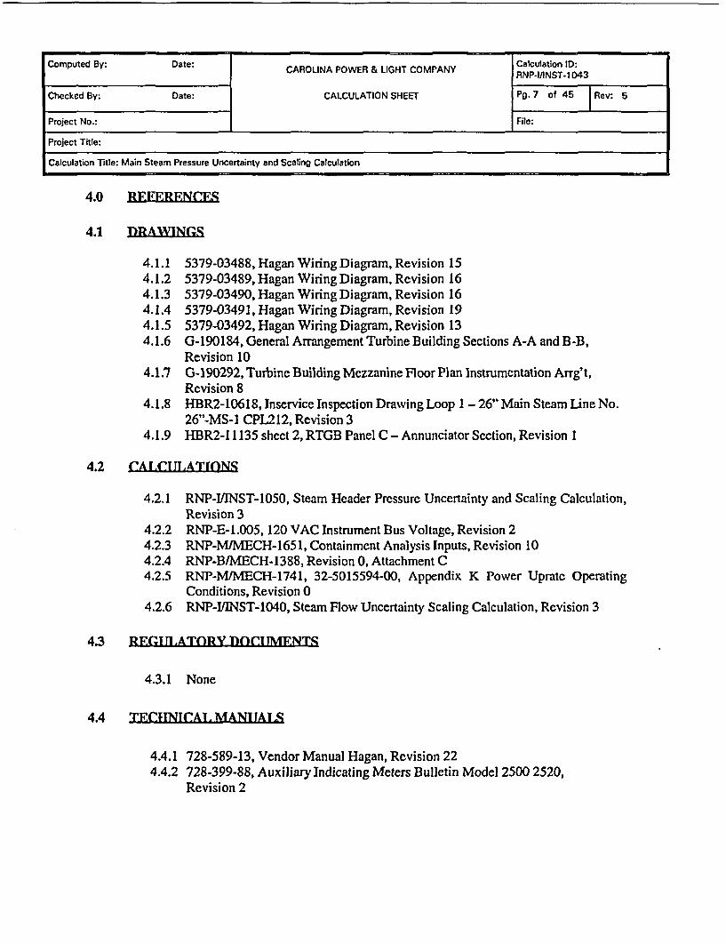
6.6.5 Trinnmitter Temperatire Effect (TF=,,,
Per Attachment B, the ambient temperature effect is ± 0.0125% URL + 0.0625% span per50 'F for transmitters with a Range Down Factor of 1: I to 5:1 (RDF = URL / CalibratedSpan). The maximum span is 2000 psig and the calibrated span is 1400 psig, so the RDF forthis application is 1.43. Per Input and Assumption 5.3, the minimum temperature is 330F andthe maximum temperature is 107 'F. For conservatism, a maximum change in temperature of74 'F is used to calculate the transmitter temperature effect. The total temperature error effectis computed as follows:
TExmtr = ± (0.0125 * URL + 0.0625% Span) 74OF)
TExmtr= (OoI25* +0.0625%Span F1400 )t.500F)
TEamtr = + 0.12% Span
6.6.6 Trtinsmitter Stntie Presqure (,;PF,,irl
Per Reference 4.7.4, each transmitter is a gauge pressure transmitter. Therefore, staticpressure effects are not applicable.
6.6.7 Transmitter Power Supply Effgct (PSF..
Per Attachment B. the power supply effect associated with the transmitters is given as lessthan ±0.005% Span per volt variation in power supplied to the transmitter. Per References4.1.1-4.1.5 and 4.7.4, each instrument loop is powered by either a NUS SP801 orWestinghouse 4111085-0001 power supply. The power supply is powered from regulatedinstrument buses. Per Reference 4.2.2 the voltage variation on the instrument buses is 7.8volts. The power supply effect is given by:
PSEzmtr = (± 0.005% Span/Volt)(7.8 Volts)
PSExmtr = ± 0.04% Span
Per Reference 4.6.1 values less than 0.05% Span are negligible and may be omitted.Therefore,
PSExmnr = N/A

Computed By: Date: CAROLINA POWER & LIGHT COMPANY ClPionT-1043
Checked By: Date: CALCULATION SHEET Pg. 16 of 45 Rev: 5
Project No.: File:
Project Title:
Calculation Title: Main Steam Pressure Uncertainty and Scaling Calculation
6.6.8 Transmitter Spigmic Error (.ry)
From, Section 5.8, the post seismic effect is as follows:
SExmtr = ± 0.25% Span
6.6.9 Normnl Trangmitter Totni ]Dviep I Incertninty (Tll tY,
Total Device Uncertainty is computed using the following equation:
TDUxmtr= ± (CALin+MTExnt+RA2+DRmt 2 +TE 2
TDUmtr = ± V(0.20 + 0.15)2 + 0.002 + 0.292+0.122
TDUxmtr = :± 0.47% Span
6.6.10 Transmittpr As Fonnd Tolpranie (AFTmt,'
Per Reference 4.6.1, the As Found Tolerance (AFT) is computed using the followingequation:
AFTxmtr = ± CALr2+DR 2 +MTE Kr
AF~xmtr = J0.22 + 0.292 + 0.1 52
AFTxmtr = ± 0.38% Span
6.6.11 Transmitter As Ieft Tnlerance (AI j tr
ALTxmtr = CALxmtr
ALTxmtr = ± 0.20% Span

Computed By: Date: CAROLINA POWER & LIGHT COMPANY RNPClcINST-1043
Checked By: Date: CALCULATION SHEET Pg. 17 of 45 | Rev: 5
Project No.: File:
Project Title:
Calculation Title: Main Steam Pressure Uncertainty and Scaling Calculation
Error Contributor Value TVpe Section
RA + 0.00% Span Random 6.6.1CAL + 0.20% Span Random 6.6.2DR + 0.29% Span Random 6.6.3
MTE + 0.15% Span Random 6.6.4TE_ +0.12% Span Random 6.6.5SE + 0.25% Span Random 6.6.8
As Left Tolerance (ALT) + 0.20% Span Random 6.6.11As Found Tolerance (AM I+ 0.38% Span Random 6.6.10Total Device Uncertainty + 0.47% Span Random 6.6.9
Transmitter Uncertainty Summary
6.7 COMPARATOR MODUl 11 F.
6.7.1 Cnmpnrntnrllnverifitd Attrihilteg nf ieference Aeeirney(RA =nmp
Per Reference 4.4.1, the comparator reference accuracy is ± 0.50% Span. Per Reference4.5.11, the comparator is calibrated to + 0.50% Span, and the calibration procedure verifiesthe attributes of linearity and hysteresis but not repeatability. Per Reference 4.6.1, thefollowing equation is utilized to compute the repeatability portion of the comparatorreference accuracy:
RA COlp 0.50% SpanRepeatability = RA m = i 0 San i 0.29% Span
Therefore,
RAcomp = + 0.29% Span
6.7.2 Ccimparatnr C'slihrztinn Tnlerance ((AlV.nm
Per Reference 4.5.1 1, the comparator is calibrated to ± 0.50% Span. Therefore,
CAIomp = ± 0.50% Span

Computed By: Date: CAROLINA POWER & LIGHT COMPANY RNP-alcNST-1043
Checked By: Date: CALCULATION SHEET Pg. 18 of 45 Rev: 5
Project No.: File:
Project Title:
Calculation Title: Main Steam Pressure Uncertainty and Scaling Calculation
6.7.3 Comparator Drift (fR,=mr
Per Reference 4.4.1, no drift is specified for the Hagan or NUS comparator. Per Reference4.6.1, if no drift is specified for a device, a default value of ± 1.00% Span may be used.Based on historical data, Hagan comparator drift is ± 0.25% Span (Attachment F). If thedefault value bounds the value obtained through a review of the historical data, the defaultvalue of + 1.00% Span may be used for comparator drift (Reference 4.6.1). Therefore, thedefault value of + 1.00% Span is used for comparator drift for the NUS and Hagancomparators.
DRcomp = ± 1.00% Span
6.7.4 Cnmpnrntnr M&TE Effect (MTFam*
Per References 4.5.1-9, one DMM with an accuracy of ± 0.25% Reading is used to calibratethe comparator. For conservatism, a maximum reading of 5 Vdc is used to compute theaccuracy of the DMM as follows:
MTEcomp = (0.25% Reading 4Vdc )= ±0.31% Span
6.7.5 Compnrsitnr Temperature Fffeet (TFmw
Per Reference 4.4.1, the NUS comparator temperature effect is given as ±0.04% Span perIOC change in temperature from the temperature at the time of calibration, and notemperature effect is specified for the Hagan comparator. Per Reference 4.6.1, if notemperature effect is specified for a device, a default value of ±0.50% Span may be used forthe temperature effect. Per Design Input 5.5, a change in temperature of 420 F (23.330 C) isused to compute the comparator temperature effect. Therefore,
TEcomp = ± 0.04% Span (2.°C JTEcomp = ± 0.93% Span
Since either Westinghouse Hagan or NUS comparator may be used, the most restrictivetemperature effect (NUS comparator) is used in this calculation.

Computed By: Date: Calculation ID:
CAROLINA POWER & LIGHT COMPANY RNP-IIINST.1043
Checked By: Date: CALCULATION SHEET Pg. 19 of 45 |Rev: 5
Project No.: File:
Project Title:
Calculation Title: Main Steam Pressure Uncertainty and Scaling Calculation
6.7.6 Caomprrstnr Powtpr Siipply Effiet (PMF, Y
Per Reference 4.4.1, no uncertainty for the comparator power supply effect is specified.Since the comparators are powered by regulated instrument buses, the comparator powersupply effect is considered to be negligible. Therefore,
PSEcomp = N/A
6.7.7 Compnrntnr Totnl lDevice I Tncertninty (TIM I...p)
Total Device Uncertainty is computed using the following equation:
TDUcomp = (CALco + MTTEcc,p) + RA 2 +D 2 + TEcon 2
TDuV,= D(0.50 + 0.31)2 + 0.29 +1.00 +0.93
TDUcomp+ 1.61% Span
6.7.8 Cnamparntor As Fouind Tnlprsnep (AFT~rrn,,2
Per Reference 4.6.1, the As Found Tolerance (AFT) is computed using the followingequation:
AFrcomp = ± VCAALCOmnp2 + DR Comp 2 + MTEc. 2
AFrcomp = ± 10.502 +1.002+ 0.312
AFTcomp = + 1.16% Span
6.7.9 Compr tor As l.pft Tn1PrnneP (AL T .
ALTcomp = CALcomp
ALTcomp = ± 0.50% Span

Computed By: Date: CAROLINA POWER & LIGHT COMPANY RNPCl/INST-1043
Checked By: Date: CALCULATION SHEET Pg. 20 of 45 | Rev: 5
Project No.: File:
Project Title:
Calculation Title: Main Steam Pressure Uncertainty and Scaling Calculation
Error Contributor Value T pe SectionRA + 0.29% Span Random 6.7.1
CAL + 0.50% Span Random 6.7.2DR + 1.00% Span Random 6.7.3
MTE + 0.3 1% Span Random 6.7.4TE + 0.93% Span Random 6.7.5
As Left Tolerance (ALT) i 0.50% Span Random 6.7.9As Found Tolerance (AF) + 1.16% Span Random 6.7.8Total Device Uncertainty i 1.61% Span Random 6.7.7
(non-accident) _
Comparator Device Uncertainty Summary
6.8 ISOLATOR~ MOTI)TILE
6.8.1 1qnlntnr'c I lnvprifierI Attrihfiltdp orf Rprenep Aerir:1cv (RA.,n,)
Per Reference 4.4.1, the reference accuracy of the NUS isolators are ± 0.10% Full Scale.Per Reference 4.5.11, the isolators are calibrated to ± 0.15% Span, and the calibrationprocedure verifies the attributes of linearity but not hysteresis or repeatability. PerReference 4.6.1, the following equation is utilized to compute the repeatability andhysteresis portions of the isolator reference accuracy:
Repeatability= RA i ,= 0.10%Span
+A ±o 0.06% SpanHysteresis = i RA 0.10%Sn = S 0.06% Span
RAisoi = ± 10.062 +0.062 Therefore,
RAiso = ± 0.08% Span
6.8.2 TIolatnr Cnflihratinn Tnlerann' (C(A I Skim
Per Rcfercnce 4.5.11, the isolators are calibrated to ± 0.15% Span. Therefore,
CALio = + 0.15% Span

Computed By: Date: CAROLNA POWER & LIGHT COMPANY Calculation ID:______________________I CAOLIA PWER& LGHTCOMANYRNP-l/INST-1043
Checked By: Date: CALCULATION SHEET Pg. 21 of 45 Rev: 5
Project No.: File:
Project Title:
Calculation Title: Main Steam Pressure Uncertainty and Scaling Calculation
6.8.3 Tholatnr Drift (=R;,,ni
Per Attachments D and E, isolator drift is specified as + 0.20% Span. Therefore,
DRi,.i = ± 0.20% Span
6.8.4 lgalstor M&TE EffPet (MTF*,R,')
Per References 4.5.1 through 4.5.9, two DMMs are used to calibrate the isolators. EachDMM has an accuracy of ± 0.10% Reading. The total MTE term is the SRSS of theindividual DMM accuracy terms. For conservatism, a maximum reading of 5 Vdc is usedto compute the accuracy of the DMMs as follows:
MTEisoi = ±_I(2 (0.10% Reading3( Vdc'~*~ 1 4 Vdc )
MTEi,0 i = ± 0. 18% Span
6.8.5 TIolatnr Temperhtire Fffeet (TCIF;:od
Per Reference 4.4.1 and Section 5.9, the bounding NUS isolator temperature effect is givenas + 0.5% Full Scale per 500F change in temperature from the temperature at the time ofcalibration. Per Design Input 5.5, a change in temperature of 420 F (23.330C) is used tocompute the isolator temperature effect. Therefore,
(=S 5 Vdc Y 100% Span Y 42OF)+0.5% Full Scale 100% FullScaleX 4 Vdc ~50OF)
TEisoi = ±0.53% Span
6.8.6 Isn1itor Power !Supply FflPet Xf;folR
Per Reference 4.4.1, no uncertainty for the isolator power supply effect is specified. Sincethe isolators are powered by regulated instrument buses, the isolator power supply effect isconsidered to be negligible. Therefore,
PSEisoi = N/A

Computed By: Date: CAROLNA POWER it LIGHT COMPANY Calculation ID:CAROINAPOWE & IGHTCOMANYRNP-IIINST.1043
Checked By: Date: CALCULATION SHEET Pg. 22 of 45 Rev: 5
Project No.: File:
Project Title:
Calculation Title: Main Steam Pressure Uncertainty and Scaling Calculation
6.8.7 Tnlatfnr Tntnl Deviep I Ineprtninty (TDl TJi,)
Total Device Uncertainty is computed using the following equation:
TDUisat = + V(CAL iSl + MTE + ) + RAsol,2 + DRv,,2 +TEi.,,2
TDUis1 = ± 1(0. 15+0.18)2 +0.082 +0.202 +0.532
TDUioI = ± 0.66% Span
6.8.8 Isolatar Ay, Fnidnrl Tnlerance (AFMhgni)
Per Reference 4.6.1. the As Found Tolerance (AFT) is computed using the followingequation:
AFrisoi = ± SCALD +DR + MTE_
AFTri,,= ± 0.152 +0.202 +0.182
AFriSOi = ± 0.31% Span
6.8.9 Iso1ntl r AR left Tnlernnrp (AT .T.,A
Per Reference 4.6.1, the As Left Tolerance (ALT) is computed using the followingequation:
ALTisoi = CALisot
ALTi501 = ± 0.15% Span

Computed By: Date: CAROLINA POWER & LIGHT COMPANY Calculation ID:CAROINAPOWE & IGHTCOMANYRNP-I/INST.1043
Checked By: Date: CALCULATION SHEET Pg. 23 of 45 | Rev: 5
Project No.: File:
Project Title:
Calculation Title: Main Steam Pressure Uncertainty and Scaling Calculation
Error Contributor Value Type Section
RA + 0.08% Span Random 6.8.1
CAL + 0.15% Span Random 6.8.2
DR + 0.20% Span Random 6.8.3
MTE + 0.18% Span Random 6.8.4
TE + 0.53% Span Random 6.8.5
As Left Tolerance (ALT) + 0.15I% Span Random 6.8.9
As Found Tolerance (AFT) + 0.3 1% Span Random 6.8.8
Total Device Uncertainty _ 0.66% Span Random 6.8.7(non-accident! . .______________ .
Isolator Module Uncertainty Summary
6 .9 IN.DICATOR
6.9.1 Ind~cntnr's Unverifiod Aftrihiit" of Rte-Prenre Acceuirncy (RAI,,,4
Per Reference 4.4.2, the reference accuracy of the indicator is + 2.00% Span and includesthe effects of linearity, hysteresis, and repeatability (Design Input 5.5). Per References4.5.1 through 4.5.9 and 4.5.11, the indicator is calibrated to ± 2.00% Span at nine points (5up and 4 down). Therefore, the calibration procedure verifies the attributes of linearity andhysteresis but not repeatability. Per Reference 4.6.1, the following equation is utilized tocompute the repeatability portion of the indicator reference accuracy:
RA1,, 2.00% SpanRepeatability = + Ail= + 2± 0 =S + 1.15% Span
Therefore,RAiod 1.15% Span
6.9.2 Indl eriffnr Calffirstion Th~rnlerpn (CAT ,,
Per References 4.5.1 through 4.5.9, the indicator is calibrated to ± 2.00% Span. Therefore,
CALind = ± 2.00% Span

Computed By: Date: CAROLINA POWER & LIGHT COMPANY RNPClcNSTi 1043
Checked By: Date: CALCULATION SHEET Pg. 24 of 45 |Rev: 5
Project No.: File:
Project Title:
Calculation Title: Main Steam Pressure Uncertainty and Scating Calculation
6.9.3 Jndeittnr Drift °R;...d
Per Attachment G. indicator drift is specified as + 1.00% Span per year. Per Reference4.6.1, the time interval between calibrations is 22.5 month (18 months + 25%), and thefollowing equation is used to compute the indicator drift:
DRn 1.00% Span 22.5 monthsD~l~d = ±12 months)
DRind = 1.37% Span
6.9.4 Indicatnr M&TE TEffert (MT, 1,,a
Per References 4.5.1 through 4.5.9, one DMM with an accuracy of ± 0.25% Reading isused to calibrate the indicator. The calibration points are cardinal points on the indicatorscale (References 4.5.1-9). Therefore, the indicator resolution is not included in the MTEterm. For conservatism, a maximum reading of 5 Vdc is used to compute the accuracy ofthe DMM as follows:
MTEind = ± (0.25% Rcading 4 Vdc) = + 0.3 1 % Span
6.9.5 Tndkietnr Tempersttiwre Fffert (TEl..
Per Attachment G, the indicator temperature effect is specified as ± 0.10% Span per 10Cchange from the temperature at the time of calibration. Per Design Input 5.2, a change intemperature of 9.40C is used to compute the indicator temperature effect.
TEind = ± 0.1O% Span( 9. )
TEind = ± 0.94% Span
6.9.6 Indlictor Power Aupply Ffef (PTSRlnd)
Per References 4.1.1 through 4.1.3, the indicators are not powered by an external source.Therefore, there is no indicator power supply effect.
PSEind = N/A

Computed By: Date: CAROLINA POWER & LIGHT COMPANY Calculation ID0
Checked By: Date: CALCULATION SHEET Pg. 25 of 45 |Rev: 5
Project No.: File:
Project Title:
Calculation Title: Main Steam Pressure Uncertainty and Scaling Calculation
6.9.7 4nrlimnfor RPndshiloty (Rftm)
Per Reference 4.6.1, the indicator readability term is 1/2 of the smallest indicator scaledemarcation. Per Reference 4.1.9, the indicator has a scale of 0 to 1400 psig with minordemarcations of 20 psig. Therefore,
( 20 psigY 100% Span 0R~ind =t ~ 2 1400psig + Span
6.9.8 Indklitnr Totvl DTevice I Ineertninty CTIJ TVA
Total Device Uncertainty is computed using the following equation:
TDUind = ±V(CAL,,d + MTEi.,)2 + RAQi2+ DRinr2+TEi,,d2+ RDind2
TDUind = ± VI(2.00+0.31)' +1.152 + 1.372 +0.942 +0.7 12
TDUind = ± 3.15% Span
6-9-9 Indictnr As Fnound 'I'nlprsnee (AFTi,.O
Per Reference 4.6.1, the As Found Tolerance (AFF) is computed using the followingequation:
AFTind =+CALnd 2 + DR id2 + 'T=in 2
AFTind = ± 12.002 + 1.372 + 0.312
AFTind = ± 2.44% Span
6-9910 lndrientnr As T gft Toleraniet (At T.Ti
Per Reference 4.6.1, the As Left Tolerance (ALT) is computed using the following equation:
ALTind = CAL-nd
ALTind = ± 2.00% Span

Computed By: Date: CAROLINA POWER & LIGHT COMPANY Calculation 043
Checked By: Date: CALCULATION SHEET Pg. 26 of 45 Rev: 5
Project No.: File:
Project Title:
Calculation Title: Main Steam Pressure Uncertainty and Scaling Calculation
Error Contributor Value T Section
RA + 1.15% Span Random 6.9.1CAL + 2.00% Span Random 6.9.2
DR + 1.37% Snan Random 6.9.3
+ 0.31% S an Random 6.9.4
TE + 0.94% Span Random 6.9.5
RD + 0.71% Span Random 6.9.7
As Left Tolerance (ALT) + 2.00% Span Random 6.9.10
As Found Tolerance (AFT) + 2.44% Span Random 6.9.9
Total Device Uncertainty ± 3.15% Span Random 6.9.8(non-accident)_
Indicator Uncertainty Summary
7.0 TOTAl. LOP ITNCFRTAINTY (TIll)
This section presents the total loop uncertainties for each function addressed by thiscalculation. Section 6.1 of this calculation provides the justification for which loopfunctions must consider accident environmental conditions. If a function is not requiredduring accident operation, no total loop uncertainty for accident operation is computed forthat function. If a setpoint must be available under normal, accident, or seismic operatingconditions, a total loop uncertainty for the setpoint is calculated for the applicableconditions.

Computed By: Date: CAROLINA POWER & LIGHT COMPANY Calculation ID:RNP_1IINST-1043
Checked By: Date: CALCULATION SHEET Pg. 27 of 45 Rev: 5
Project No.: File:
Project Title:
Calculation Title: Main Steam Pressure Uncertainty and Scaling Calculation
7.1 Tntnl hong llneertsninty - Plnnt normal
7.1.1 Tntfl l.nnp l hnwrtninty- -Inrkirtnr
PT-474 475 476, 4R4 4R5 446- 494, 49- andA49
Per Reference 4.6.1, the total loop uncertainty associated with the indicator is computedwith the following equation:
TLUind = ± VTDU,T,, +TDU^,o,2 +TDUid 2 + norPME
TLUind = 0.472 +0.662 +3. 12 + 0.0% Span
TLUind = ± 3.25% Span
TLUi0d = ± 45.50 psig
7.1.2 Tntnl lInnp llnertninty-iniiu tn .RFES
Per Reference 4.6.1, the total loop uncertainty at the input to ERFIS is computed with the
following equation:
TLUERMF = ± TDUim¢ 2+2*TDU-,502 + norPME
TLUERFIS =± N0.472 +2*0.662 +O.O% Span
TLUERFIS = ± 1.05% Span
TLUERFIS = + 14.70 psig
7.1.3 TatAl loop Uneeroninty Cnmpirntnr (pregiuirp input tn high stesm flnw/lowstean preccllr
ptC-474A, 4RSA 496A
Per Refcrcnce 4.6.1, the total loop uncertainty for the pressure setpoint input to the HighSteam Low/Low Steam Line Pressure safeguards trip that is computed with the followingequation:

Computed By: Date: CAROLINA POWER & LIGHT COMPANY Calculation ID:RNP-IA1NST-1 043
Checked By: Date: CALCULATION SHEET Pg. 28 of 45 Rev: 5
Project No.: Fite:
Project Title:
Calculation Title: Main Steam Pressure Uncertainty and Scaling Calculation
TLUcomp = + TDU.I +TDUCO. +2norPME
TLUcomp = ± 0.472 + 1.612 + 0.0% Span
TLUcomp = ± 1.68% Span
TLUcomp = ± 23.52 psig
7.1.4 Totni 1 np1 Tnrf~Int prrstnr (ctem preuire differentizil'
PMU4-74R 475 476 4R4 48R1 4R6 494, 495 426B
Per Reference 4.6.1, the total loop uncertainty for the pressure setpoint input to the highsteam pressure differential safeguards trip is computed with the following equation:
TLUsP/sP±=±|TDUt ,2 +TLUshp 2+TDUCOM 2 + norPME + norPMEsnpcss
Where:
TLUshp = + 2.21% Span (from Section 7.1.3 of Reference 4.2.1)
norPMESHpress = ± 0.0% Span (from Section 6.4 of Reference 4.2.1)
TLUsp/sp = ± 10.472 + 2.212 + 1.6 12 + 0.0% Span + 0.0% Span
TLUsp/sp =:± 2.77% Span
TLUsr/sp = ± 38.78 psig
7.2 Tnatl lonnp UTnertninfy - Arrident
Per Section 6.1 the Accident Error is 0. Therefore the Total Loop Uncertainty - Accident isthe same as normal operating.
7.3 Tntsl I.nnp llnrertninty - Pn-tAccidtent
Per Section 6.1 the Accident Error is 0. Therefore the Total Loop Uncertainty - PostAccident is the same as normal operating.

Computed By: Date: CAROLINA POWER & LIGHT COMPANY Calculation ID:
Checked By: Date: CALCULATION SHEET Pg. 29 of 45 |flew 5
Project No.: File:
Project Title:
Calculation Title: Main Steam Pressure Uncertainty and Scaling Calculation
7.4 Totil Loop I Inrertninty - Poct .Sigmi'
Pcr Reference 4.7.7 the instrument loop must remain operable post seismic.
7.4.1 Totsl T .oop I Inrertninly - Tndlentnr
P1-474 475 476 484 4R5 4R6, 494- 45 nnnd 496
Per Reference 4.6.1, the total loop uncertainty associated with the indicator is computedwith the following equation:
TLUind = +-4TDUxiii2 +TDUisol2 +TDUind2 +SExntt2 +norPME
TLUind = ± 10.472 + 0.662 + 3. 152 +0.252 + 0.0% Span
TLUind = ± 3.26% Span
TLUind = ± 45.64 psig
7.4.2 Tnt-ml I.oop IT ncertsinty - input to RFIRS
Per Reference 4.6.1, the total loop uncertainty at the input to ERFIS is computed with thefollowing equation:
TLUERFIS = ± VTDU,.,2 + 2*TDU1 , 012 +SE,,,r 2 + norPME
TLUERFIS = + 0.47 + 2 * 0.662 + 0.252 + 0.0% Span
TLUERFIS = ± 1.07% Span
TLUERRiS = ± 14.98 psig

Computed By: Date: CRLN OE IH OPN aclto D
CARLINA PRNP-IIINST-1043
Checked By: Date: CALCULATION SHEET Pg. 30 of 45 Rev: 5
Project No.: File:
Project Title:
Calculation Title: Main Steam Pressure Uncertainty and Scaling Calculation
7.4.3 Totnl nns 1ineeirtfninty Comparntor (pricciwre input La high stegm flnwflowsteam precsre
Pry-474A,4RSA 496A
Per Reference 4.6.1, the total loop uncertainty for the pressure setpoint input to the highsteam flow/low steam pressure safeguards trip that is computed with the followingequation:
TLUs =±VTDU x 2 +TDU 2+SE 2 + norPMEl
TLUSF1SP = ±- .472 +1.612 +0.252 +0.0% Span
TMUsFsp = ± 1.70% Span
TLUsF/sP= ± 23.80 psig
7.4.4 Total Loop 1nrertfninty Comparator (stenm prdsllr T diffprentinl)
PC--47413 475 476 494 4RSR 4R6, 494 495 496F
Per Reference 4.6.1, the total loop uncertainty for the pressure setpoint input to the highsteam pressure differential safeguards trip is computed with the following equation:
TLUsp/sp = ± jTDU~t 2, TU + 2 +TDU 2 +SE,.,, 2 + norPME + norPMEsnpress
Where:TLUsp = 2.27% Span (from Section 7.4.1 of Reference 4.2.1)
norPMEpsH~p, = ± 0.0% Span (from Section 6.4 of Reference 4.2.1)
TLUspisp = ± 10.472 + 2.272 + 1.6 1I + 0.252 + 0% Span + 0% Span
TLUsp/sp = ± 2.83% Span
TLUsp/sp = ± 39.62 psig

Computed By: Date: CAROLINA POWER & LIGHT COMPANY Calculation ID:CAROINAPOWE & IGHTCOMANYRNP-IJINST-11 043
Checked By: Date: CALCULATION SHEET Pg. 31 of 45 Rev: 5
Project No.: File:
Project Title:
Calculation Title: Main Steam Pressure Uncertainty and Scaling Calculation
7.4.5 Tntal lJnnp I ne~rtainty-Input to .Stenm Flow
The main steam pressure transmitters provide an input to the steam flow circuitry fordensity compensation per Reference 4.2.6, Sections 5.17 and 6.4.1. Per Reference 4.6.1,the total loop uncertainty for the pressure input to the steam flow circuitry is computed withthe following equation:
ThUSE = ±TDU 2 +SE. 2
TLUSF = ± ,0.472 + 0.252
TLUSF = ± 0.53% Span
TLUsF= ± 7.42 psig
7.5 T.OOP AS FOIND TOLF.RANCE.
7.5.1 Lnop AR Friinnd Tolerrnnce - Indirator
PT-474. 475 476 4R4 4R5, 486i 494 4Q5 nnd 496
Per Reference 4.6.1, the following equation is used to calculate the indicator Loop as FoundTolerance (LAFTind):
LAFTid = ±AD 2 + AFIr,0 2 + AF1 2
LAFTijd = +10.3 82 +0.312 +2.442
LAFTind = + 2.49% Span
LAFTind = ± 34.86 psig
7.5.2 ltoop AN Fniind TO1PrrnceP-nplft nFRFIT;
Per Reference 4.6.1, the following equation is used to calculate the ERFIS input Loop asFound Tolerance (LAFTERIS):
LAFTERflS = ± 4AFr 2 +2 * AFI1,2
LAirER"s =± 140.382 +2*0.312

Computed By: Date: CAROLINA POWER & LIGHT COMPANYCalculation ID:CAROINAPOWE & IGHTCOMANYRNP-IIINST-1 043
Checked By: Date: CALCULATION SHEET Pg. 32 of 45 |Rev: 5
Project No.: File:
Project Title:
Calculation Title: Main Steam Pressure Uncertainty and Scaling Calculation
LAFIrERFiS = + 0.58% Span
LAFTERIS = ± 8.12 psig
7.5.3 1 nwAg Fmi'nd Tflertnnce - Inpnt tn H1igh S;teim FlawII .raw !St arm Precur
Per Reference 4.6.1, the following equation is used to calculate the High Steam Flow/LowSteam Pressure input to safeguards actuation (LAFTsFlsr):
LAFrSFsp = + AFT, 2 + AfJ 2
LAFrsF/sp= +±N0.382+1.162
LAFSpF/sp = + 1.22% Span
LAFsF/sP= ± 17.08 psig
7.5.4 Unap AS Fmindl Talvrsne - TInpuit In Stexim Preqssirp fifferentinl)
Per Reference 4.6.1, the following equation is used to calculate the Steam PressureDifferential input to safeguards actuation (LAFrsp/sp):
LAFTspisp ± +VAAT2 + AFC2 + LAFrShp2
Where:LAFI'shp is the Loop As Found Tolerance Steam Header Pressure = ± 1.41% Span(from Section 7.5.3 of Reference 4.2.1)
LAFTspisp= + 10.38' +1.162 +A112
LAFrsp/sp = + 1.87% Span
LAFrsp/sp = ± 26.18 psig
7.6 CGROtP ASR F1TNI) TOT.FRAN!C
7.6.1 Gr;u11 AS Eamd Thlerrnwp - Tndira ot
Pr-474 475 476 4R4 4R5 4R6 494 495 AND 496

Computed By: Date: CAROLINA POWER & LIGHT COMPANY RNP-ClcNST-1043
Checked By: Date: CALCULATION SHEET Pg. 33 of 45 Rev: 5
Project No.: File:
Project Title:
Calculation Title: Main Steam Pressure Uncertainty and Scaling Calculation
Per Reference 4.6.1, the following equation is used to calculate the indicator Group As FoundTolerance (GAF~ind):
GAFrInd = ± VAFVIso + AFTid2
GAFrird = ± /0.312 + 2.44-
GAFsind = ± 2.46% Span
GAFrind = ± 34.44 psig
7.6.2 Grnonp As Found Tnlernnet - Inpilt to E.RFIS
Per Reference 4.6.1, the following equation is used to calculate the ERFIS Group As FoundTolerance (GAF-IERrs):
GAFTERFRS = ± 2*AFFU.i 2
GAFTERFis = ±2 0.312
GAFITERFIS = + 0.44% Span
GAFTERFS = ± 6.16 psig
7.6.3 Grntip As Found TnIernnep - Input tn High SRlt#nm FlnwIt.nw Stfsm Pre.ssre
Per Reference 4.6.1, the following equation is used to calculate the High Steam Flow/LowSteam Pressure input to safeguards actuation (GAFTsr/,sP):
GAFTspsp = +AFT,
GAFTSF/SP = ± 1.16% Span
GAFTIsvsP = + 16.24 psig
Computed By: Date: CAROLINA POWER & LIGHT COMPANY RNP-I/INST 1043
Checked By: Date: CALCULATION SHEET Pg. 34 of 45 |Rev: 5
Project No.: I File:
Project Title:
Calculation Title: Main Steam Pressure Uncertainty and Scaling Calculation
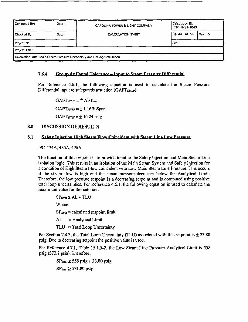
7.6.4 Grntp As Fnwind Tleranee - Tnpitt to .Spenm Prepsigre Differentiatl
Per Reference 4.6.1, the following equation is used to calculate the Steam PressureDifferential input to safeguards actuation (GAFTspisp):
GAFTsp/sp = + AFT
GAFT'sptsp = 1. 16% Span
GAFTsp/sp± 16.24 psig
8.0 DISCI TSSION (OF RF0IT ITS
8.1 Snfety lnteetion High Stp nm Flnw Cnincilent wifh Stenm Iine 1 nw Precquire
PC-474A 4RSA 496A
The function of this setpoint is to provide input to the Safety Injection and Main Steam Lineisolation logic. This results in an isolation of the Main Steam System and Safety Injection fora condition of High Steam Flow coincident with Low Main Steam Line Pressure. This occursif the steam flow is high and the steam pressure decreases below the Analytical Limit.Therefore, the low pressure setpoint is a decreasing setpoint and is computed using positivetotal loop uncertainties. Per Reference 4.6.1, the following equation is used to calculate themaximum value for this setpoint:
SPfirt 2 AL + TLU
Where:
SPjit = calculated setpoint limit
AL = Analytical Limit
TLU = Total Loop Uncertainty
Per Section 7.4.3, the Total Loop Uncertainty (TLU) associated with this setpoint is ± 23.80psig. Due to decreasing setpoint the positive value is used.
Per Reference 4.7.1, Table 15.1.5-2, the Low Steam Line Pressure Analytical Limit is 558psig (572.7 psia). Therefore,
SP1ij, 2 558 psig + 23.80 psig
SPlimit 2 581.80 psig

Computed By: Date, CAROLINA POWER & LIGHT COMPANY Calculation ID:CAROINAPOWE & IGHTCOMANYRNP-I/INST*1043
Checked By: Date: CALCULATION SHEET Pg. 35 of 45 |Rev: 5
Project No.: File:
Project Title: l
Calculation Title: Main Steam Pressure Uncertainty and Scaling Calculation
Per References 4.5.1,4.5.5, and 4.5.9 the Main Steam Line Low Pressure setpoint is currentlyset to 614 psig decreasing. This is the Technical Specification nominal trip setpoint. TheMargin (M) associated with this setpoint is computed as follows:
M = Calibrated Setpoint - SPlimit
M = 614 psig - 581.80 psig
M = 32.20 psig
Per Section 7.6.3 of this calculation, the Group As Found Tolerance (GAFT) is ± 16.24 psig.Per Reference 4.6.1, the Allowable Value (AV) associated with this setpoint is computed asfollows:
AV > SP - GAFF, where SP is the calibrated setpoint
AV 2 614 psig - 16.24 psig
AV 2 597.76 psig
Per Section 7.5.3 of this calculation, the Loop As Found Tolerance (LAFT) is ± 17.08 psig.Per Reference 4.6.1, the Channel Operability Limit (COL) is computed as follows:
COL = SP-LAFT, where SP is the calibrated setpoint
COL = 614 psig - 17.08 psig
COL = 596.92 psig

Computed By: Date: CAROUNA POWER & LIGHT COMPANY RNP-luINST-1043
Checked By: Date: CALCULATION SHEET Pg. 36 of 45 Rev: 5
Project No.: File:
Project Title:
Calculation Title: Main Steam Pressure Uncertainty and Scaling Calculation
Setpoint (614 psig decreasing)A6 AL
Group As Found Tolerance (16.24 psig)Loop As Found Tolerance (17.08 psig)
Calculated Allowable Value(597.76 psig)
_ Channel Operability Limit (596.92 psig)
.A tionalMargi ( 32.20 psig)
_ I
4Bias Pressure = 558 + 23.8 = 581.8 psig
Total Loop Uncertainty (23.80 psig)
Analytical Limit (558 psig)-I
Safety Injection High Steam Flow Coincident With Steam Line Low PressureDliagram
8.2 Stpnm Linp High Difrerpnfinl PresCglrP
Pr74R T47s 476 4PR4 4ARM 4ARA6 Q4 AQ; A96R
The function of this setpoint is to provide input to the Safety Injection and Main Steam Lineisolation logic. This results in an isolation of the Main Steam System and Safety Injectionfor a condition of High Steam Line Differential Pressure. This occurs if the Steam Headerand Main Steam Line Pressures are different due to a steam line rupture on the SteamGenerator side of the Main Steam Isolation Valves. During normal operations, a 20 to 30psig differential exists between the Main Steam Line and the Steam Header. Per Reference4.2.3, safety analyses assume a setpoint value of 100 psig ± 60 psig with satisfactory results.This provides two analytical limit values for evaluation; 40 psig and 160 psig. The logiccircuitry functions by sensing when Main Steam Line Pressure increases above SteamHeader Pressure to yield the predetermined (setpoint) differential of 100 psig. Therefore,this is a setpoint actuated by an increasing process signal, so negative uncertainties are usedwhen evaluating the adequacy of the setpoints / allowable values.

Computed By: Date: CAROLINA POWER & LIGHT COMPANY Calculation ID:HNP4IINST-1043
Checked By: Date: CALCULATION SHEET Pg. 37 of 45 TRev 5
Project No.: File:
Project Title:
Calculation Title: Main Steam Pressure Uncertainty and Scaling Calculation
Seftpnint Fvallatiton with 160 PSCTG Annlyticnl L imit
Per Reference 4.6.1, the following equation is used to calculate the maximum value for thissetpoint using the 160 psig Analytical Limit:
SPlimit < AL - TLU where,SPji = calculated setpoint limitAL = Analytical LimitTLU = Total Loop Uncertainty
Per Section 7.4.4, the total loop uncertainty (TLU) associated with this setpoint is+ 39.62 psig. Per Reference 4.7.2, the nominal trip seipoint is 100 psig. The setpoint isevaluated below against the 160 psig Analytical Limit.
SP1imit < 160 psig - 39.62 psigSPumit 5 120.38 psig
Per Reference 4.7.2, the nominal trip setpoinl is 100 psig differential. The Margin (M)associated with this setpoint is computed as follows:
M = SPunt - Calibrated SetpointM = 120.38 psig - 100 psigM = 20.38 psig
Per Section 7.6.4 of this calculation, the GAFF is ± 16.24 psig. Per Reference 4.6.1, theAllowable Value (AV) associated with this setpoint is computed as follows:
AV < SP + GAFIT, where SP is the calibrated setpointAV 100 psig + 16.24 psigAV < 116.24 psig
Per Section 7.5.4 of this calculation, the Loop As Found Tolerance (LAFT) is ± 26.18 psig.Per Reference 4.6.1, the Channel Operability Limit (COL) is computed as follows:
COL = SP + LAFG, where SP is the calibrated setpointCOL = 100 psig + 26.18 psigCOL= 126.18 psig

Computed By: Date: CAROLINA POE & LIGHT COMPANY Calculation ID:Iud~: Das H _ Pm fi > __RNP-IANST-1043
Checked By: Date: CALCULATION SHEET Pg. 38 of 45 |Rev: 5
Project No.: File:
Project Title:
Calculation Title: Main Steam Pressure Uncertainty and Scaling Calculation
'tptrint RliVfhI1tirn with 40 P2.TG Analytica1l l imit
Per Reference 4.6.1, the following equation is used to calculate the minimum value for thissetpoint using the 40 psig Analytical Limit:
SPmit 2 AL + TLU where,SPfnit = calculated setpoint limitAL = Analytical LimitTLU = Total Loop Uncertainty
Per Section 7.4.4, the Total Loop Uncertainty (LU) associated with this setpoint is± 39.62 psig. Per Reference 4.7.2, the nominal trip setpoint is 100 psig. The setpoint isevaluated below against the 40 psig Analytical Limit.
SPHimjc > 40 psig + 39.62 psigSPit 2 79.62 psig
Per Reference 4.7.2, the nominal trip setpoint is 100 psig differential. The Margin (M)associated with this setpoint is computed as follows:
M = Calibrated Setpoint - SPtimitM = 100 psig - 79.62 psigM = 20.38 psig
Per Section 7.6.4 of this calculation, the GAFr is ± 16.24 psig. Per Reference 4.6.1, theAllowable Value (AV) associated with this setpoint is computed as follows:
AV 2 SP - GAFI, where SP is the calibrated setpointAV > 100 psig - 16.24 psigAV > 83.76 psig
Per Section 7.5.4 of this calculation, the Loop As Found Tolerance (LAFI) is ± 26.18 psig.Per Reference 4.6.1, the Channel Operability Limit (COL) is computed as follows:
COL = SP - LAFr, where SP is the calibrated setpointCOL= 100 psig-26.18 psigCOL = 73.82 psig

Computed By: Datc: CAROLINA POWER & LIGHT COMPANY RNP-IIINST 1043
Checked By: Date: CALCULATION SHEET Pg. 39 of 45 1Rev: 5
Project No.: File:
Project Title:
Calculation Title: Main Steam Pressure Uncertainty and Scaling Calculation
Analytical Limit (160 Psig)
_ e ioopUncertainty (39.62 psig)
Channel Ovcrabilitv Limit (126.18 vsiz)I
Loop AFT (26.18 psig)
-� 4. Calculated Allowable Value (Sl 16.24 psig)
I MMargin 20.38 psig IGroup AFT (16.24 psig)
X Setpoint (100 psig)
L Li Group AFT (16.24 psig)Total Loop Uncertainty (39 )Calculated Allowable Value (>83.76 nsiu)
I A t.. I'l' I . Channel Operabilitv Limit (73.82 Asia)4 F -Up ttr- J tZu. 10 PNlgI
Margin (20.38 psig)Analytical Limit (40 psig)
Steam Line High Differential Pressure
The diagram above demonstrates that the nominal trip setpoint of 100 psig is adequate toprotect either analytical limit.
8.3 Impaet on Jmprrveld Teehnienl 1pedlfientinns
Table 3.3.2-1 item g (High Steam Flow coincident with low steam line pressure) allowablevalue is 2 605.05 psig. The calculated value is 2597.76 psig. The Technical Specificationvalue is conservative with respect to the calculated value.
Table 3.3.2-1 item L.e Allowable Value for the Steam Line Differential pressure is given as< 108.95 psig. The calculated Allowable Value for this trip setpoint is <116.24 psig(283.76 psig). The Technical Specification Value is conservative with respect to thecalculated values.

Computed By: Date: CAROLINA POWER & LIGHT COMPANY Calculation _0:RNP-I/INST.1043
Checked By: Date: CALCULATION SHEET Pg. 40 of 45 Rcv 5
Project No.: File:
Project Title:
Calculation Title: Main Steam Pressure Uncertainty and Scaling Calculation
8.4 lmpactnJn I AR
There is no impact on the UFSAR.
8.5 Tmpnrt nn fe"dgn Rnda 1)lwiDmenmc
There is no impact on Design Basis Documents.
8.6 Impaet on fthpr Cnfleuiatinns
The outputs of this calculation are inputs to and impact the following calculations:
RNP-II1NST-1040RNP-VINST-1050RNP-I/INST-1 120RNP-I/INST-I 121RNP-I/INST-1 122RNP-I/INST-1 124RNP-I/INST-1 125RNP-IIINST-1 144RNP-F/NFSA-0045
8.7 Impact nn Phint PrnePif ir"
The results of this calculation impact the following plant procedures:
LP-901 LP-906LP-902 LP-907LP-903 LP-908LP-904 LP-909LP-905 MMM-006 Appendix B-3PIC-845

Computed By: Date: CAROLINA POWER & LIGHT COMPANY RNP-I/INST 1043
Checked By: Date: CALCULATION SHEET Pg. 41 of 45 Rev: 5
Project No.: File:
Project Title:
Calculation Title: Main Steam Pressure Uncertainty and Scaling Calculation
9.0 SCALING CALCUlATIONS
9.1 PRFSSI IRF TRANSMITTER ( 7T-4744749 47. 4X4, 4X5 48.86 494 495 496)
Per Section 3.0, the pressure transmitters are Rosemount model 3051NG Smart PressureTransmitters, Range Code 5. which has an upper and lower range limit (URL and LRL) of2000 psig and -2000 psig, respectively (per Attachment B). Per Reference 4.5.11, the MainSteam Pressure transmitters are calibrated 0 to 1400 psig (4-2OmAdc) 1-5Vdc. Therefore,the span of each loop is 1400 psig.
Per Reference 4.7.6 and field measurements, the pressure transmitters are located 20.03 feetbelow the instrument tap. Per Reference 4.2.4, the nominal post power up-rate steam headerpressure is 800.5 psia. A sensing line fill fluid of pure water at 900F and 800.5 psia is usedto determine the hydrostatic head on the transmitter using the following equation:
Hydrostatic Head = ph144
Hydrostatic Head = 8.66psi
Where,h = height of sensing line
= 20.03 feet
p = sensing line fill fluid density used for scaling= 62.26799 Ibmnft3 @ 90°F, 800.5 psia
NOTE: The factor 144 is used to convert from lbf/ft to lbf/in2. At standard gravity,Ibm may be replaced with lbf.
The hydrostatic head is converted to voltage units as follow:
{ 8.66psig _ 5Hydrostatic head = 4Vd I 0.025Vdc
1400psig)
The following equation is used to compute the required voltage output for a given pressure(P) input to the transmitter:
E ( 4Vdc )l400psig) +.0d

Computed By: Date: CAROLINA POWER & LIGHT COMPANY Calculation ID:RNP-I/INST- 1043
Checked By: Date: CALCULATION SHEET Pg. 42 of 45 |Rev: 5
Project No.: File:
Project Title:
Calculation Title: Main Steam Pressure Uncertainty and Scaling Calculation
The equation is modified to account for the hydrostatic head by subtracting the voltagerepresentation of the hydrostatic head from the 1.000 Vdc pedestal as follows:
E ( 4Vdc P+0.975Vdc
Per Section 6.6.10 of this calculation, the As Found Tolerance (AFT) of the transmitter is± 0.38% Span. Per Section 6.6.11 of this calculation the As Left Tolerance (ALT) of thetransmitter is ± 0.20% Span. The AFT and ALT are converted to voltage units utilizing thefollowing equations:
AFr(Vdc) = ± 4Vd AFT(%Span) = ±4Vd( 0.38%Span = ±0.015 Vdc100) 100)
ALT(Vdc) = ±4Vd-( ALT(%Span) = ±4Vdrf 0.2%Span ±0.008 VdcT100) e100w
The calibration table for the transmitter is as follows:
Required Output Desired Input As Found Tolerance As Left Tolerance
(psig) (Vdc) (Vdc) (Vdc)
0 0.975 0.960 to 0.990 0.967 to 0.983
350 1.975 1.960 to 1.990 1.967 to 1.983
700 2.975 2.960 to 2.990 2.967 to 2.983
1050 3.975 3.960 to 3.990 3.967 t
1400 4.975 4.960 to 4.990 4.967 to 4.983

Computed By: Date: CAROLINA POWER & LIGHT COMPANY Calculation ID:_______________________ I CROLNA OWE & LGHTCOMANYRNP-l/INST-1043
Checked By: Date: CALCULATION SHEET Pg. 43 of 45 1Rev: 5
Project No.: File:
Project Title:
Calculation Title: Main Steam Pressure Uncertainty and Scaling Calculation
9.2 IS^OLATOR MODl E (PM.474f, 475C, 476, 4AMR. 48511 486B1 4941) 495C, 4961.PM-474A, 475A. 476A, 484A, 485A, 4864A 494A, 495A, 496AI
The isolator transfer function is as follows:
Eo = Et
Per Section 6.8.8 of this calculation, the As Found Tolerance (AFT) of the isolator is± 0.31% Span. Per Section 6.8.9 of this calculation the As Left Tolerance (ALT) of theisolator is ± 0.15% Span. The AFT and ALT are converted to voltage units utilizing thefollowing equations:
AFT(Vdc) = + 4Vdc( AFT(%Span) +4Vd 0.31 %Span = ±0.012 Vdc100 ) io
ALT(dc) 4V(ALT(%Span) = ±4Vd (0.15%7Span ±006 dALT(Vdc) = ±4VdcI (0O P 100 c 100 =+00006 Vdc
The calibration table for isolator as follows:
Required input Desired Output As Found Tolerance As Left Tolerance
(Vdc) (Vdc) (Vdc) (Vdc)
1.000 .000 0.988 to 1.012 0.994 to 1.006
2.000 2.000 1.988 to 2.012 1.994 to 2.006
3.000 3.000 2.988 to 3.012 2.994 to 3.006
4.000 4.000 3.988 to 4.012 3.994 to 4.006
5.000 5.000 4.988 to 5.012 4.994 to 5.006
Computed By: Date: CAROLINA POWER & LGHT COMPANY Calculation ID:CAROINAPOWE & IGHTCOMANYRNP.IAlNST-1 043
Checked By: Date: CALCULATION SHEET Pg. 44 of 45 Rev: 5
Project No.: File:
Project Title:
Calculation Title: Main Steam Pressure Uncertainty and Scaling Calculation
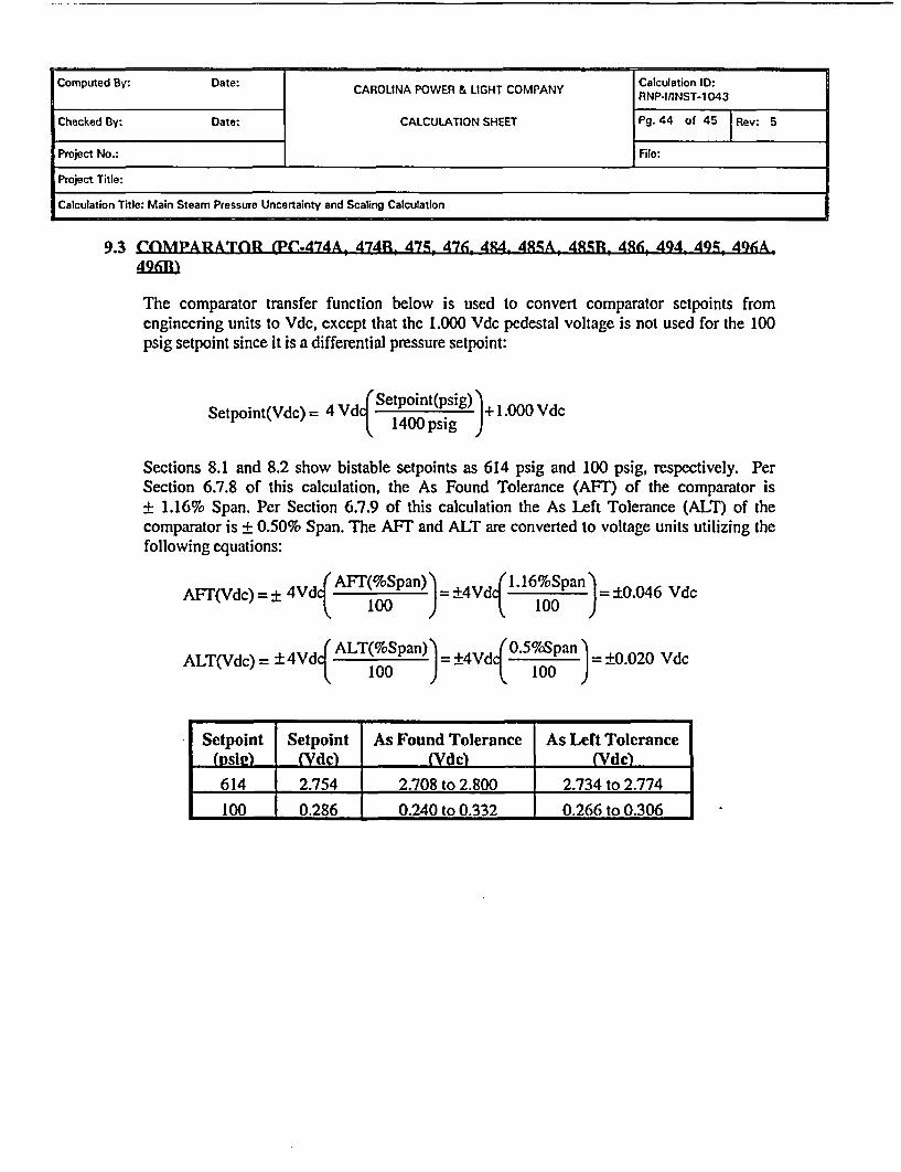
9.3 COMPARATOR (Pf?-474A, 474R, 475, 476. 484, 4ALA 48ARU 486, 494. 495, 496A,496H)
The comparator transfer function below is used to convert comparator setpoints fromengineering units to Vdc, except that the 1.000 Vdc pedestal voltage is not used for the 100psig setpoint since it is a differential pressure setpoint:
Setpoint(Vdc) = 4 Vd Setpoint(psig) + 1.000 Vdc1400 psig
Sections 8.1 and 8.2 show bistable setpoints as 614 psig and 100 psig, respectively. PerSection 6.7.8 of this calculation, the As Found Tolerance (AFT) of the comparator is± 1.16% Span. Per Section 6.7.9 of this calculation the As Lert Tolerance (ALT) of thecomparator is ± 0.50% Span. The AFT and ALT are converted to voltage units utilizing thefollowing equations:
AFI'(Vdc) = ± 4Vd A 100p ) =+4Vd .16%Span = ±0.046 Vdc
(ALT(%Span) (0.5%7SpanALT(Vdc) = ±4Vdq =0 ±4Vdc 100 = 0.020 Vdc
Setpoint Setpoint As Found Tolerance As Left Tolerance(vSi2 (Vdc) (Vdc)614 2.754 2.708 to 2.800 2.734 to 2.774100 I 0.286 0.240 to 0.332 0.266 to 0.306
Compted y: Dte: alculation ID:Computed By: Date: CAROLINA POWER & LIGHT COMPANY RNP.I/INST-1043
Checked By: Date: CALCULATION SHEET Pg. 45 of 45 | e:5
Project No.: File:
Project Title:
Calculation Title: Main Steam Pressure Uncertainty and Scaling Calculation
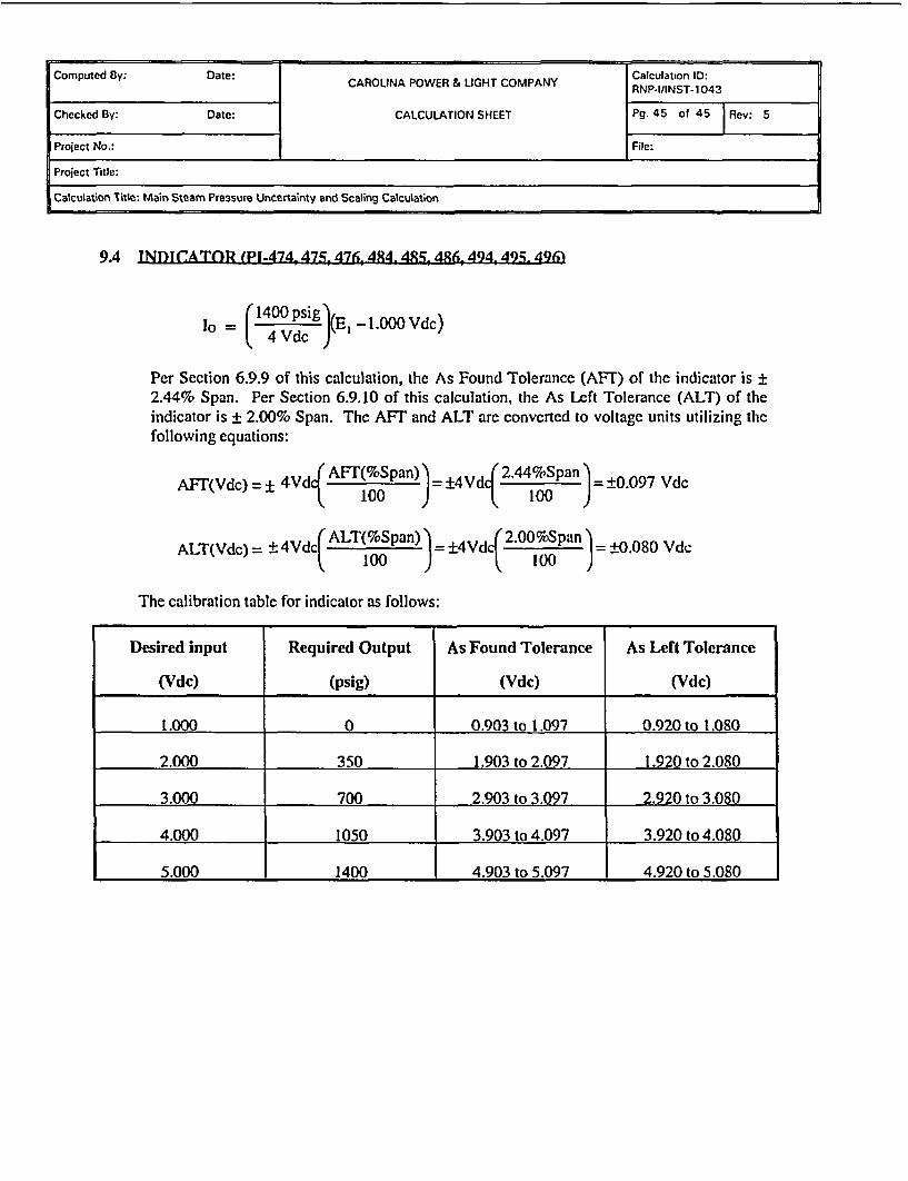
9A INDIC(ATOR (PI-474 475 476, 484 48R5 4.6 494, 494) 496i
lo = (1400 psig(E -1.OOOVdc)
Per Section 6.9.9 of this calculation, the As Found Tolerance (AFT) of the indicator is ±2.44% Span. Per Section 6.9.10 of this calculation, the As Left Tolerance (ALT) of theindicator is ± 2.00% Span. The AFT and ALT are converted to voltage units utilizing thefollowing equations:
AF'(Vdc) = 24Vdc AFT(%Span) )= ±4Vdc 2.44%Span ±0.097 WCAF(d)=±4d~ 100 3 =±.07 d
ALT(Vdc) = ±4Vdci (%Spa=n ±4Vdc 2.00oSpan =+0.080 Vdc100 100
The calibration table for indicator as follows:
Desired input Required Output As Found Tolerance As Left Tolerance
(Vdc) (psig) (Vdc) (Vdc)
t.000 0 0.903 to 1.097 0.920 to 1.080
2.000 350 1.903 to 2.097 1.920 to 2.080
3.000 700 2.903 to 3.097 2.920 to 3.080
4.000 1050 3.903 to 4.097 3.920 to 4.080
5.000 1400 4.903 to 5.097 4.920 to 5.080

Computed By: Date: CAROLINA POWER & LIGHT COMPANY RNPCluINSTo1043
Checked By: Date: CALCULATION SHEET Pg.1 of 1 Rev: 5
Project No.: ATTACHMENT A File:
Project Title:
Calculation Title: Main Steam Pressure Uncertainty and Scaling Calculation
ATTACHMENT ACALCULATION MATRIX REFERENCE TABLE
DOCUMENT NUMBER DOCUMENT TITLE
TYPE OFDOCUMENTDrawing 5379-03488 Hagan Wiring DiagramDrawing _ 5379-03489 Hagan Wiring DiagramDrawing 5379-03490 Wiring DiagramDrawina _ 5379-03491 Hagan Wiring DiagramDrawing5379-03492 Hagan Wiring DiagramDrawing G-1 90184 General ArrangementDrawing G-1901 92 Turbine BuildingDrawingHBR2-1 0618 Inservice InspectionDrawing HBR2-11135 sheet 2 RTGBCalculation RNP-IIINST-1 050 Steam Header Pressure UncertaintyProcedu ire l P-901 to LP-909 Loop Calibration ProceduresProcedure PIC-845 Rosemount Smart TransmittersProcedure EGR-NGGC-01 53 Engineering SetpointsProcedure TMM-026 Reg Guide 1.97Calculation RNP-l/INST-1 120 Uncertainty of Manual Feed Flow
Calorimetric Calculation per OST-01 2Calculation RNP-I/INST-1 121 Uncertainty of ERFIS Feed Flow
_Calorimetric CalculationCalculation RNP-l/INST-1 122 Uncertainty of ERFIS Steam Flow
__ ICalorimetric CalculationCalculation RNP-I/INST-1 124 ERFIS Steam Flow Automatic
Calorimetric Uncertainty CalculationCalculation RNP-I/INST-1 125 ERFIS Feed Flow Automatic Calorimetric
IUncertaintV CalculationCalculation RNP-l/INST-1 143 ULFM FW Flow and Temperature Unc.Calculation RNP-l/INST-1 144 ULFM Feed Flow Based Automatic
Calorimetric Uncertainty CalculationCalculation RNP-M/MECH-1 651 Containment Analysis InputsCalculation RNP-I/INST-1 040 Steam Flow Loop Uncertainty and
Scaling CalculationDBD DBD/R87038/SDO6 Reactor Safeguards and Protection
SystemDBD '0381SD25 Main Steam System
Computed By: Date: CAROLINA POWER & LIGHT COMPANY RNP-tniNS I1043
Checked By: Date: ATTACHMENT B Pg91 of 3 Rev: 5MODEL 3051N SMART PRESSURE TRANSMITTER FOR
NUCLEAR SERVICE I
Project No.: I File:
Project Title:
Calculation Title: Main Steam Pressure Uncertainty and Scaling Calculation
00813-0100-4808English
August 2001Rev. DA
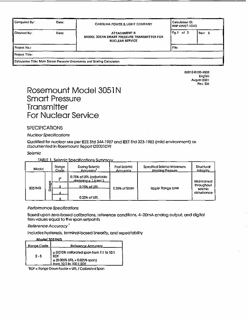
Rosemount Model 3051 NSmart PressureTransmitterFor Nuclear ServiceSPECIFICATIONSNuclear Specifications
Qualified for nuclear use per IEEE Std 344-1987 and IEEE Std 323-1983 (mild environment) asdocumented In Rosemount Report D2001019
Seismic
TABLE Seismnic Specifictio s Summ__c_
Range During Seismic Post Seismic Specified Seismic Maximum StructuralModel Code Accuwr ov' Acnt irUcv Working Prepssure Intgrity
0.75% of URL (adoustableo doamping = 16 snc'l Maintained
CD throughout3051NG 0 3 075% of URL 0.25% of Span Upper Range LimIt seismic
4 cdisturbance_ 0.25% of URL
Performance Specifications
Based upon zero-based calibrations, reference conditions, 4-20rnA analog output, and digitaltrim values equal to the span setpoints
Reference Accuracy'
Includes hysteresis, terminal-based linearity, and repeatability
Mndeifl 3me-,N
Rone Cod Reference Accurracy
± 0.075% calIbrated span from 1:I to 10:12 - 5 RDF
± (0.005% URL + 0.025% span)I from 101 to 1001 RDF
'RDF = Range Down Factor = URL / Calibrated Span

Computed By: Date: CAROLINA POWER & LIGHT COMPANY RNPalculST-1043
Checked By: Date: ATTACHMENT B Pg.2 of 3 Rev: 5MODEL 3051N SMART PRESSURE TRANSMITTER FOR
NUCLEAR SERVICE
Project No.: .Fire
Project Title:
Calculation Title: Main Steam Pressure Uncertainty and Scaling Calculation
Drift
nrint AQFAN ) NCZ' NA
Rn .deDriftI 1t (0OZI. URL + 0.2%O SPAN) FOR 30 MONTHS
2 - 5 : 0.2% URL FOR 30 MONTHS
Ambient Temperoture Effect' 2
Mirdg 3ns1 N ) I Nt;
Qange Cr de Ambtent Temrnferatie Fffect rer F0F (28°Cr
O 025 R 0 05t'% sonn)
± (0.1% URL + 0.25% span) from 1:1 to 30:11 (0 14% URL + 0 lS% ron) from 301 to 50 1
2 -5 ± (0.0125% URL + 0.0625% span) from 1:1 to 5:1_ (0025% IRI + 0 125% soon) from 5S1 to 100 1
RDF = Range Down Factor = URL I Calibrated SpanExposure of isolator diaphragms to process temperatures above 185 OF (85'C) but below 250 IF (121 *C) produces a temperatureeffect of ±1.0% of calibrated span In addition to the effects listed.
Power Supply Effect
Less than ±0.005% of calibrated span per volt for RDF S 10.

Computed By: Date: CAROLINA POWER & LIGHT COMPANY Calculation ID:
Checked By: Date: ATTACHMENT B Pg.3 ol 3 Rev: SMODEL 3051N SMART PRESSURE TRANSMITTER FOR
NUCLEAR SERVICE
Project No.: File:
Project Title:
Calculation Title: Main Steam Pressure Uncertainty and Scaling Calculation
Span and Zero, Zero Elevation, and Suppression
Zero and span values can be set anywhere within the range limits stated in Table 2, provided sensor limitsare not exceeded.Span must be greater than or equal to the minimum span stated in Table 2.
_ TALE2. odels3051 N anQ51 NG Range and Sensor LimitsRange Minirmm Span _M___ ann and Sensor rllmits
Lowe PIl
Model 3051 ND. NG Upper (URL) Model 3051 NO Model 3051 ND
O 0.1 in -20 (25Pal 3.0 In H20 (750 Pa1 -3.0 in H20 (-750 Pal NA
1 0.5 in H20 (0 12 kPa) 25 in H20 (6.22 MPa) -25 in 1-H20 (-6.22 ePa) NA
2 9 2.5 in H20 (0 2 9k~p 250 in H20 (62.2 kPa) -250 in H20 (-6.22 kPa) -250 in W20 (-62.2 kPa)
3 10 in H20 (2.48 kPa1 tOOOInH 20(248 kPa) .1000 in H 220f-248kPa1 0.5 sla (3.5 kPa abs)
4 3 psI (20.7 kPal 300 psi (2 070 ePa) -300 pSi (-2 070 kPa1 0.5 psia (3.5 kPa nbs)
5 20 DSi l138 kPa) 2000 Dsi (13 800 kPa1 *2000 psi (-13 800 kPa) 0.5 osia (3.5 kPabs1
Maximum Working Pressure
Mnfdp 3051 N.J
Static pressure limit
Mnlel 3051 NG ane Mn4odal 30Q1 NA
Upper range limit1. EPR process 0-ring (Code B) Is limied to 2000 psi maximum working pressure.2. See Table 1 for specified Seismic Maximum Working Pressure.

Computed By: Date: _ ACalculation ID:CAROINAPOWE & IGHTCOMANYRNP-IAINST-1043
Checked By: Date: ATTACHIMENT C Pg.1 of 1 Rev: 5
Project No.: File:
Project Title:
Calculation Title: Main Steam Pressure Uncertainty and Scaling Calculation
[DELETED]

Computed By: Date: CAROLINA POWER & LIGHT COMPANY Calculation 0D:
Checked By: Date: CALCULATION SHEET Pg.1 of 2 |Rev: 5
Project No.: ATTACHMENT 0 File:
Project Title:
Calculation Title: Main Steam Pressure Uncertainty and Scaling Calculation
ATTACHMENT I)NUS Instruments Long Term Drift Test for NUS Modules - Final Report, Executive
NUSinstrUments
440 West Broadway - Idaho Falls, ID 83402 - Phone: 208-529-1000 - Fax: 208-524-9238
October 26, 2001
Pat HartigFirstEnergy Nuclear Operating CompanyBeaver Valley Power StationP.O.Box 4Shippingport, Pa 15077
Subject: Long Term Drift Test 4LTDT) Results for NUS modules - Final Report, ExecutiveSummary
Dear Mr. Pat Hartig:
NUS Instruments (NUSI), undertook a research and development project in 1996 to re-engineer instrumentation for use as replacements for the obsolete Hagan line of nuclearplant instrumentation. The NUSI replacement modules were designed originally usingspecifications written by Public Service Electric and Gas (PSE&G). The final specificationsincorporated both original Hagan published specifications and new or additional plant-specific requirements. The final agreed upon specification formed the design basis for theNUS Instruments 800 Series product line that has been sold to many nuclear plantsincluding Salem, H.B. Robinson, Turkey Point and Diablo Canyon.
NUSI has been requested by FENOC to supply instrumentation drift specifications for the800 Series modules. We understand that these numbers are to be used to determinerequirements for plant calibration cycles for these modules. The calibration cycle may beextended if it can be shown that the drift of the replacement modules is below specifiedcriteria. This change would result in a significant savings in plant maintenance costs.
NUSI was contracted by PSE&G to conduct a 36-month Long Term Drift Test (LTDT).This test was conducted on four classes of modules with four units of each type for atotal of sixteen modules undergoing the test. The four classes of modules consisted offour Dual Alarm Modules (DAM), four One-channel Analog Isolators (OCA), four RTDAmplifiers (RTD), and four Four-Channel Summing Modules (SUM). A loop of instrumentswas also tested to determine overall loop drift.

Computed By: Date: CAROLINA POWER & LIGHT COMPANY Calculation ID:
Checked By: Date: CALCULATION SHEET Pg.2 of 2 {Rev: 5
Project No.: ATTACHMENT D File:
Project Title:
Calculation Title: Main Steam Pressure Uncertainty and Scaling Calculation
A1TACHMENT D (Cont)NUiS Instruments Long Term Drift Test for NUS Modules - Final Report, Executive
Drift was specified as a percentage of the upper range limit (URL) over an 18-monthperiod. After 36 months of testing, NUSI can proudly state that all modules performedbetter than the stated specification. The specification and summary results are givenbelow.
PEIFIIITEST R *SULTSACCURACY DRIFT DRIFT (%URL) 2 sigma DRIFT
MODULEC LA S S_ _ _ _ _ _ _ _ _ _ _ _ _ _ _ _ _ _ _
RTD Q. LQA% 0940 % 0.365 %OCA 0.5% _ 0.2% 0 048 % 0.074 %DAM 0.5% 0.3% 0.083 % 0.127 %SUIMQ. 5°0 0.6% 0.135 % 0.214 %LQOP 0.5% INotspecified 0 115 % 0 186 %
NUSI is currently in the process of preparing the final test report which will provide greaterdetails about the test modules and fixture, test procedure and processes, data andsampling intervals, analysis and plots showing the data trends. This data represents over26,000 hours of testing and over 24,000 individual data measurements. NUSI can makeavailable upon request the Excel 97 workbook that provides the data, analysis, andnecessary graphing tools. This report will be available October 31, 2001.
It is also worth noting that several utilities have been conducting their own independentlong term drift tests of a instruments installed in their loops. They can independentlysupport that the NUSI 800 Series instruments meet or exceed the long term driftspecification.
Please contact NUS Instruments for additional information.
SCIENTECH, Inc., NUS Instruments440 West BroadwayIdaho Falls, Idaho 83402(208) 529-1000 (LaWanda Wold or Heath Buckland)
Respectfully,
LaWanda WoldFacility Manager, Nt
Office Address:SCIENTECH - Broadway440 West BroadwayIdaho Falls, Idaho 83402-3638208.524.9200 Front Desk208.524.9282 Fax
JS InstrumentsWork Phono: 208.524.9236Facsimile: 208.524.9238E-mail: LWold(scientech.com

Computed By: Date: CAROLINA POWER & LIGHT COMPANY Calculation ID:
Checked By: Date: CALCULATION SHEET Pg.1 ol 2 Rev: 5
Project No.: ATTACHMENT E File:
Project Title:
Calculation Title: Main Steam Pressure Uncertainty and Scaling Calculation
UEmnif frnm NTI innfirming Similarity of N nl] rafnlir Mfodlidec dafted O1UlSMi2
From: James [email protected]: Tuesday, January 15,2002 11:54 AMTo: [email protected].: Series SC993 and Series 800 Isolators
Series SC993 isolators were manufactured by us under the names of EnergyIncorporated, El Electronics, El Systems and El International. They are an earlyversion of stand alone isolator intended for electrical isolation of the inputs from theoutputs. They were encapsulated and had terminal blocks for connection of power,inputs and outputs. They were single channel devices. The power supply used was anearly type of switching power supply that is no longer manufactured. The isolationcircuitry was basically the same as is currently used in all NUSI isolators and many ofour other instrumentation devices. The actual isolation element, the Burr-Brown 3656is identical to that used today. All devices manufactured then underwent dielectricwithstand testing of 3000 Vdc and at 2500 Vac to ensure their readiness to isolate apotential fault. They also were 100% functional tested. The units were encapsulatedwith an epoxy and aluminum oxide based compound that made them impervious tovirtually all environmental concerns and seismically were considered a "brick". Theywere qualified simply by their mounting constraints. Internal heating was not a concernas the potting compound used had a very high thermal conductivity. Outputs andpower were fused on the top surface of the aluminum chassis. Span and zeroadjustments were also mounted there. The device is simple internally and externally. Ithas many years of reliable performance at several nuclear plants with little or no unduemaintenance issues. The only know life issue is the power supplies used (then andnow) have aluminum electrolytic capacitors with know life characteristics of abouttwenty years. Pots should not be adjusted unless the unit is out of tolerance to reducethe wear and tear on them. If a typical maintenance cycle is used, the devices willeasily achieve their twenty year life expectancy with no problems. The limited lifecharacteristics will not affect their isolation specifications in any way. These deviceshad only limited surge protection circuitry (on the inputs) included. Outputs and powerports may be susceptible to damage from surges but will not pass this to the inputs.
NUS Instruments currently manufactures devices that are form, fit and functionreplacements for the SC993 series. These are the SCA101 devices in the SCA100series of isolators. These devices differ from the SC993 in the power supply used andthat the chassis is 1/16' deeper than the older versions. These devices have surgesuppression circuitry and have been surge tested on all ports. Fault testing and otherisolation parameter testing has been completed on these devices. All otherparameters, including the circuitry and elements used do not differ from the SC993series.

Computed By: Date: CAROLINA POWER & LIGHT COMPANY RNP-lINSTi1043
Checked By: Date: CALCULATION SHEET Pg.2 of 2 Rev: 5
Project No.: I ATTACHMENT E File:
Project Title:
Calculation Title: Main Steam Pressure Uncertainty and Scaling Calculation
Series 800 devices were manufactured by us under the names Haliburton NUS,Haliburton NUS Environmental Corp., NUS Corp. and NUS Instruments. They are stillin production. These devices include FCA, OCA and FIA versions with seriesdesignations 800 and 801. The only differences are the number of channels loaded,test jack size and LED power indicator colors. These devices all use modern switchingpower supplies in varying numbers dependent upon the output ranges and isolatortypes. FIA isolators have a separate power supply for each channel to give the outputsisolated commons. The circuit is operationally the same as earlier types and the actualisolation element is still the Burr-Brown 3656. These devices have undergone completeisolation type testing for dielectric withstand of 3000 Vdc and 1000 Vac, and mostproduction units are tested to these values. The devices under went fault type testingto 480 Vac and 140 Vdc applied to all ports in the FIA800 series. Shorts, opens andinter-channel effects have also all been type tested. The devices have also been testedfor surge withstand using the waveform specified in IEEE 472. All production units are100% functionally tested prior to shipment. The chassis and electronics have beenseismically proof tested for operation before, during and after the defined DBE with noanomalies. These devices use an aluminum chassis that is intended for rackmounting. The internals are accessible and passive air flow through the chassisremoves internally generated heat. Outputs are fused on the rear and power is fusedon the front of the devices. Span and zero adjustments are located on the front plate ofthe devices. These devices have the same life characteristics in the power suppliesused but since they are not potted, the power supplies may be replaced allowing for theisolators to have 40 year life expectancies.
All devices are manufactured using a 10CFR50 appendix B quality assurance programand are provided with 1 OCFR part 21 traceability as basic components.
J.E. Siedelmann, P.E.Sr. Design Engineer
NUS Instruments, Inc.Phone: (208) 524-9246
Fax: (208) 524-9238jsiedelmann~scientech.com
440 W. Broadway, Idaho FallsIdaho 83402-3638

Computed By: Date: Calculation ID:CARONA POWER & LIGHT COMPANY RNP-IIINST-1043
Checked By: Date: CALCULATION SHEET Pg. 1 of 1 RIv: 5
Project No.: ATTACHMENT F File:
Project Title:
Calculation Title: Main Steam Pressure Uncertainty and Scaling Calculation
ATTACHMENT FComparator Historical Drift Study
cM SE nM T
aq." " IID I SC1 =l C"~AlA=~
SC * 141 IC.949 VPC-14SA SIt143
Cal. Vt. Pavia. Cal. Vt. Davia. Cal. ft. |Dvia. Cal. Vt. Pavia.
7/&1,/9 9/2*/S4 3/2/".001
.001 9/23/53 .000 5/2s/13.001 .003
4/04/85 3/24/86 2/231t 2A02/1.001 .002 .oo .001
5/13/37 9/23/37 4/3/3d7 227/37.003 .002 .009 .003
4/13/81 9/30/53 12/21**3 2/5/38.003 .004
11/20/89 .001 .009 7/4/3
V2/219 9/22100
3.LCAX II=i III 301.AL 4XRAAM
LC 10" LC_1038 tC.IaA, LC-1035
Cal.Sc. Devis. Vavis. Dvrij. DeVLa. DPvei. Dayis. Davis. D"Is.
.000 .000 .001 .004 .000 .000 .OC .000~/01/85
.001 .000 .001 .001 .001 .000 IVA IVA4/13/35
.001 .001 .001 .000 .001 .000 IVA I/A3/03/57
.001 .003 .001 .001 .0041 .001 3/A N/A4/0,/a'
.000 .001 .002 .000 .002 .001 YA 3/A
.000 .000 _ _ _ _ .003 .0034/04/10
* asxtrt e.t Nalfimetis*X/A 3kt Aval1ab1e
tAxLmm devIati.. meted btwes the *1-r *a 1s-loft valua$ ecartdd on the*awiable salibrstlea data shets was .009 Vdc.
This vale. Le arexmaatcei equal to 0.=.

Computed By: Date, CAROLINA POWER & LIGHT COMPANY Calculation ID:
Checked By: Date: CALCULATION SHEET Pg. 1 of 1 IRcv: 5
Project No.: ATTACHMENT G File:
Project Title:
Calculation Title: Main Steam Pressure Uncertainty and Scaling Calculation
ATTACHMENT GIndicator Specifications
_ _Umosm
- T3Od~Y. C. *T.~ ftnRo*OM Sent~~w ~ C ~~TWE: 740.450,00*2
P&E~aOK £1 .S537
June 24, "l~
CAROLINA PGWrR & LIBHTP.0. DoN 155lRaleigh, MC 27602-1551
Attn: Robert Mann OHS 6th Floor
Dear Robert,
Per our conv sation the drift and T.C. for InternationalZnstruwnts .odel 2520 are 12 of upon per year and * 1 of spanper degree C respectIvely. The accur-cy following a seismicevent are per l1l Btandards for shock and vibration and ar-quoted as X of span. Understand that the assuaption is ^d-that the selsaic event reflects both shock and vibration.
Should you )Iave any further Inlormation, please do not he-l-
lamlesonVice President
cc: Keith tlacdawall

ATTACHMENT 2Sheet 1 of 1
Record of Lead Review
Design RNP-UINST-1043 Revision 5The signature below of the Lead Reviewer records that:
- the review Indicated below has been performed by the Lead Reviewer,- appropriate reviews were performed and errors/deficiencies (for all reviews performed) have
been resolved and these records are included in the design package;- the review was performed In accordance with EGR-NGGC-0003.
E Design Verification Review D Engineering Review E Owner's ReviewD Design ReviewEl Alternate CalculationEl Qualification Testing
a Special Engineering Review
El YES 0 N/A Other Records are attached.
Frank Modlin/ ,Mai. Y)1 Electrical 08/13/02Lead Reviewer (print/sign) Discipline Date
Item Deficiency ResolutionNo. Rslto
No comments
FORM EGR-NGGC-0003-2-5This form is a QA Record when completed and Included with a completed designpackage. Owner's Reviews may be processed as stand alone QA records whenOwner's Review is completed.
I EGR-NGGC-0003 I Rev 8 1 _